CN102469010A - A method and network equipment for distributing MPLS labels - Google Patents
A method and network equipment for distributing MPLS labels Download PDFInfo
- Publication number
- CN102469010A CN102469010A CN2010105382803A CN201010538280A CN102469010A CN 102469010 A CN102469010 A CN 102469010A CN 2010105382803 A CN2010105382803 A CN 2010105382803A CN 201010538280 A CN201010538280 A CN 201010538280A CN 102469010 A CN102469010 A CN 102469010A
- Authority
- CN
- China
- Prior art keywords
- identifier
- network
- network device
- logical domain
- correspondence
- Prior art date
- Legal status (The legal status is an assumption and is not a legal conclusion. Google has not performed a legal analysis and makes no representation as to the accuracy of the status listed.)
- Granted
Links
Images


Classifications
-
- H—ELECTRICITY
- H04—ELECTRIC COMMUNICATION TECHNIQUE
- H04L—TRANSMISSION OF DIGITAL INFORMATION, e.g. TELEGRAPHIC COMMUNICATION
- H04L45/00—Routing or path finding of packets in data switching networks
- H04L45/50—Routing or path finding of packets in data switching networks using label swapping, e.g. multi-protocol label switch [MPLS]
- H04L45/507—Label distribution
-
- H—ELECTRICITY
- H04—ELECTRIC COMMUNICATION TECHNIQUE
- H04L—TRANSMISSION OF DIGITAL INFORMATION, e.g. TELEGRAPHIC COMMUNICATION
- H04L45/00—Routing or path finding of packets in data switching networks
- H04L45/02—Topology update or discovery
- H04L45/04—Interdomain routing, e.g. hierarchical routing
Landscapes
- Engineering & Computer Science (AREA)
- Computer Networks & Wireless Communication (AREA)
- Signal Processing (AREA)
- Data Exchanges In Wide-Area Networks (AREA)
Abstract
The invention provides a method for distributing MPLS labels and network equipment. The method for distributing the MPLS label comprises the following steps: a first device receives a BGP protocol message sent by a second device, wherein the BGP protocol message carries a service identifier of the second device; the first device establishes a corresponding relation between the first device and the second device according to the service identifier of the first device and the service identifier of the second device; and the first equipment allocates MPLS labels for the corresponding relations. The invention realizes the MPLS label distribution aiming at a certain specific logical relation between two nodes under the BGP protocol, so that the network equipment running the BGP protocol can efficiently acquire the MPLS label corresponding to the specific logical relation.
Description
Technical Field
The present invention relates to the field of communications, and in particular, to a method and a network device for allocating MPLS labels.
Background
MPLS is an abbreviation for Multi-Protocol Label Switching (Multi-Protocol Label Switching). MPLS uses short, fixed-length labels (labels) to encapsulate packets, enabling fast forwarding in the data plane. In the control plane, MPLS has a powerful and flexible routing function of an IP network, and can meet the requirements of various new applications on the network.
This technique was originally proposed to increase the forwarding speed of routers. Compared with the traditional IP routing mode, the method only analyzes the IP message header at the network edge during data forwarding, and does not need to analyze the IP message header at each hop, thereby saving the processing time.
With the development of ASIC technology, route lookup speed has not been a bottleneck hindering the development of networks. This makes MPLS no longer a significant advantage in increasing forwarding speed. However, MPLS supports the connection-oriented characteristics of a multi-layer label and a forwarding plane, and is widely applied to Virtual Private Networks (VPNs), traffic engineering, Quality of Service (QoS), and the like.
MPLS is forwarded based on labels, and the distribution and distribution of MPLS labels can be completed through static configuration, and also can be completed through protocols such as LDP, RSVP-TE, BGP and the like. Wherein, the RSVP-TE is mainly used for completing the establishment of the TE LSP; the LDP can be applied to the establishment of a routing topology driven LSP or can be used as a signaling protocol of a Pseudo Wire (PW) label in the L2 VPN; the Border Gateway Protocol (BGP) is mainly to extend the signaling protocol as private network route label under VPN and the LSP establishment of label routing under cross-domain VPN.
At present, a BGP protocol running on a certain device can only distribute, according to a certain specific service element, such as a VPN route, a VPN instance, a VPLS instance, and so on, one or a set of MPLS labels that are the same as those corresponding to the service element to all other devices that establish BGP protocol neighbors with the device.
Disclosure of Invention
An object of the present invention is to provide a method and network device for allocating MPLS labels.
The technical scheme of the invention is as follows:
the invention discloses a method for distributing MPLS labels, which comprises the following steps:
a first device receives a BGP protocol message sent by a second device, wherein the BGP protocol message carries a service identifier of the second device;
the first device establishes a corresponding relation between the first device and the second device according to the service identifier of the first device and the service identifier of the second device;
and the first equipment allocates MPLS labels for the corresponding relations.
The invention also discloses a network device, which is characterized by comprising a BGP protocol message receiving unit, a corresponding relation establishing unit and an MPLS label distributing unit;
the BGP protocol message receiving unit is used for receiving a BGP protocol message sent by another network device, and the BGP protocol message carries a service identifier of the other network device;
the corresponding relation establishing unit is used for establishing the corresponding relation between the network equipment and the other network equipment according to the service identification of the network equipment and the service identification of the other network equipment;
the label distribution unit is used for distributing MPLS labels for the corresponding relations.
The invention has the advantages that the MPLS label distribution is realized aiming at a certain specific logical relation between two nodes under the BGP protocol, so that the network equipment running the BGP protocol can efficiently acquire the MPLS label corresponding to the specific logical relation.
Drawings
FIG. 1 is a flow diagram of a method according to an embodiment of the present invention;
FIG. 2 is a flow diagram of a method of one embodiment of the present invention;
fig. 3 is a schematic diagram illustrating message transmission and reception according to an embodiment of the present invention;
fig. 4 is a schematic diagram illustrating message transmission and reception according to an embodiment of the present invention;
FIG. 5 is a schematic diagram of a network device according to an embodiment of the invention;
FIG. 6 is a schematic diagram of a network device according to an embodiment of the invention;
fig. 7 is a schematic diagram of a network device according to an embodiment of the present invention.
Detailed Description
The invention is described in detail below with reference to the figures and the specific embodiments. However, it should be noted that the following examples are only examples for helping understanding the technical solutions, and are not intended to limit the present invention.
As shown in fig. 1, an embodiment of the present invention provides a method for allocating a multi-protocol label switching (MPLS) label to a network device, which is applied to a network system including a first device and a second device.
11. A first device receives a BGP protocol message sent by a second device, wherein the BGP protocol message carries a service identifier of the second device;
12. the first device establishes a corresponding relation between the first device and the second device according to the service identifier of the first device and the service identifier of the second device;
13. and the first equipment allocates MPLS labels for the corresponding relations.
Optionally, the service identifier of one device may include a device identifier of the device, and thus, the service identifier of the first device and the service identifier of the second device respectively include the device identifier of the first device and the device identifier of the second device. The device identifier refers to an identifier capable of uniquely identifying the device, such as an IP address of the device.
When the service identifier of a device includes the device identifier of the device, a two-tuple (device identifier 1, device identifier 2) including two elements, i.e., the device identifier of the first device and the device identifier of the second device, may be used to represent the correspondence between the first device and the second device.
Optionally, the service identifier of a device may further include a logical domain identifier of the device and a device identifier of the device. The logical domain refers to a virtual network formed by interconnecting at least two local area networks, hosts, routers or other network devices through a public network tunneling technology. Preferably, the logical domain includes a layer three virtual private network (L3VPN), a layer two virtual private network (L2VPN), and the like, wherein the L2VPN includes a virtual private local area network service (VPLS) and a virtual private line service (VPWS). Preferably, the logical domain Identifier includes a Route Target (RT), a Route differentiation Identifier (RD), a virtual private local area network service Identifier (VPLSID), an Access Identifier (AI), and/or an Access Circuit Identifier (ACI).
Correspondingly, the service identifier of the first device includes a logical domain identifier of the first device and a device identifier of the first device; the service identifier of the second device includes a logical domain identifier of the second device and a device identifier of the second device.
When the service identifier of the device includes the logical domain identifier of the device and the device identifier of the device, the first device determines whether the first device and the second device are in the same logical domain according to the logical domain identifier of the first device and the logical domain identifier of the second device.
And if the first equipment and the second equipment are in the same logic domain, the first equipment establishes the corresponding relation between the first equipment and the second equipment.
Representing a correspondence of the first device and the second device using a duplet including two elements of a device identification of the first device and a device identification of the second device; the triple including the same three elements of the logical field identifier, the device identifier of the first device, and the device identifier of the second device may also be used to represent the correspondence relationship between the first device and the second device.
Preferably, in this implementation, the BGP protocol message is a BGP UPDATE message (BGP UPDATE message) defined by RFC4271 of the Internet Engineering Task Force (IETF).
Preferably, in this embodiment, the first device sends the MPLS label to the second device, so that the second device communicates with the first device by using the MPLS label.
And after receiving the MPLS label sent by the first equipment, the second equipment sends a message to the first equipment by using the MPLS label to realize communication with the first equipment.
Preferably, the first device may further send a BGP protocol packet to the second device. And the BGP protocol message carries the service identifier of the first equipment. And the second equipment establishes the corresponding relation between the first equipment and the second equipment according to the service identifier of the first equipment and the service identifier of the second equipment. And the second equipment allocates MPLS labels for the corresponding relations. Preferably, in this implementation, the BGP protocol message is a BGP UPDATE message (BGP UPDATE message) defined by RFC4271 of the Internet Engineering Task Force (IETF).
The method for assigning a label to the first device by the second device is substantially the same as the method for assigning a label to the second device by the first device in this embodiment.
The MPLS label assigned by the second device is independent of the MPLS label assigned by the first device. Preferably, the second device sends the MPLS label allocated to the second device to the first device, and the first device communicates with the second device according to the MPLS label allocated to the second device. In this way, the first device and the second device can both communicate with each other using tags assigned by each other.
Preferably, the first device and the second device are network devices capable of performing routing or switching functions, and include a switch, a router, a packet-switching-based network device, or a multi-service access node device.
Preferably, the network system further includes other network devices capable of performing routing or switching functions, for example, a third device. And the first equipment, the second equipment and other network equipment which can execute routing or switching function carry out label distribution between each two equipment, and use labels distributed by the opposite terminal to carry out communication with the opposite terminal.
When any one of the first device, the second device and other network devices capable of executing routing or switching functions allocates MPLS labels to other devices, each other device is allocated with a different label.
For example, when the first device, the second device and the third device perform label allocation, the label1-2 allocated to the second device by the first device and the label1-3 allocated to the third device are different, so as to avoid generating label collision. Similarly, the label2-1 assigned to the first device by the second device is different from the label2-3 assigned to the third device.
In addition, for a plurality of devices that perform MPLS label assignment with respect to each other, such as the first device, the second device, and the third device, a label assigned to one device by the other device is independent from a label assigned to the one device by the other device.
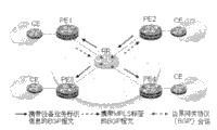
As shown in fig. 2, in one embodiment of the invention, a network operating an L2VPN as shown in fig. 3 includes PE1 as a first device, PE2 as a second device, PE3 as a third device, PE4 as a fourth device, and a Route Reflector (RR). The contents of this embodiment are as follows.
21. The PE1 receives a BGP protocol message sent by the PE2, wherein the BGP protocol message carries a service identifier of the PE2, and the service identifier comprises a logical domain ID of the PE2 and a device identifier (PE ID). In the present embodiment, the logical domain ID of PE1 is Route Target (RT)1, and the logical domain ID of PE2 is RT 2; the PE ID of PE1 is PE1 ID, the PE ID of PE2 is PE2ID, and the logical domain where PE1 is located is an L2VPN, where the L2VPN includes virtual private local area network service (VPLS) and virtual private line service (VPWS). Preferably, the PE ID is an IP address of the PE; as shown in fig. 3, PE1 receives the BGP protocol packet sent by PE2 through the RR. Optionally, the logical domain ID may also be a Route differentiation Identifier (RD), a virtual private local area network service Identifier (VPLS ID), an Access Identifier (AI), and/or an Access Circuit Identifier (ACI). Preferably, in this implementation, the BGP protocol message is a BGP UPDATE message (BGP UPDATE message) defined in RFC4271 of the IETF.
22. PE1 determines whether the logical domain ID of PE2 is the same as the logical domain ID of PE1, and if so, determines that PE1 and PE2 are in the same logical domain, i.e., in the same L2VPN, and performs step 23;
23. the PE1 establishes the corresponding relation between the PE1 and the PE2 according to the same logical domain ID, the PE1 ID and the PE2 ID. Preferably, the correspondence may be represented by a triplet (same logical domain ID, PE1 ID, PE2 ID).
24. And the PE1 allocates MPLS labels for the corresponding relation between the PE1 and the PE 2. Preferably, PE1 assigns an MPLS label to a triplet (same logical domain ID, PE1 ID, PE2 ID).
Preferably, as shown in fig. 3, PE1 sends the MPLS label to PE2 after PE1 allocates the MPLS label. PE1 may send the MPLS label to the RR, which in turn sends the MPLS label to PE 2.
Preferably, after PE2 receives the MPLS label, PE2 encapsulates the packet using the MPLS label, and sends the packet encapsulated with the MPLS label to PE 1.
Preferably, as shown in fig. 4, PE1 correspondingly sends a BGP protocol packet carrying the service identifier of PE1 to PE 2; PE2 determines whether the logical domain ID of PE2 is the same as the logical domain ID of PE 1; if the logical domain IDs are the same, the PE2 establishes the corresponding relation between the PE2 and the PE1 according to the same logical domain ID, the PE1 ID and the PE2 ID; and the PE2 allocates MPLS labels for the corresponding relation between the PE2 and the PE 1.
The MPLS label assigned by PE1 and the label assigned by PE2 are independent of each other. Thus, both PE1 and PE2 receive the MPLS label assigned by the other. After that, PE1 and PE2 respectively use the MPLS label assigned by the other party to send messages to the other party.
Similarly, PE1 may also allocate tags to PE3 and PE4, and receive the tags allocated by PE3 and PE4, so that MPLS tags allocated by the other parties may be used for packet transmission between PE1 and PE3, and between PE1 and PE 4.
Further, as for the PE1, PE2, PE3, and PE4, any two PEs may assign an MPLS label to each other and communicate with each other using the MPLS label assigned by each other.
One PE allocates different MPLS labels to different other PEs.
The MPLS labels allocated by different PEs are independent of each other.
Optionally, the RR may also not be included in the network described in this embodiment, in this case, a fully linked BGP session may be established between the PEs. Accordingly, the PE1 does not receive a BGP protocol packet through the RR, and does not send a label assigned to another device through the RR.
In one embodiment of the present invention, a network running a three-tier virtual private network (L3VPN) comprises PE1 and PE2, which preferably further comprises PE 3.
One embodiment of the present invention is as follows.
31. The PE1 receives a BGP protocol message sent by the PE2, wherein the BGP protocol message carries a service identifier of the PE2, and the service identifier comprises a logical domain ID and a PE ID of the PE 2. In this embodiment, the logical domain ID is a Route Target (RT). Accordingly, the logical domain ID of PE1 is RT1, and the logical domain ID of PE2 is RT 2; the PE ID of PE1 is PE1 ID, the PE ID of PE2 is PE2ID, and the logical domain where PE1 is located is L3 VPN. Optionally, the logical domain ID may also be a route differentiation Identifier (RD), a virtual private local area network service Identifier (VPLS ID), an Access Identifier (AI), and/or an Access Circuit Identifier (ACI). Preferably, the PE ID is an IP address of the PE or other information capable of uniquely identifying the PE. Preferably, in this implementation, the BGP protocol message is a BGP UPDATE message (BGP UPDATE message) defined in RFC4271 of the IETF.
32. PE1 determines whether the logical domain ID of PE2 is the same as the logical domain ID of PE1 and, if so, performs step 33, wherein, if the logical domain ID of PE2 is the same as the logical domain ID of PE1, it indicates that PE1 and PE2 are in the same L3 VPN;
33. the PE1 establishes the corresponding relation between PE1 and PE2 according to the same logical domain ID, PE1 ID and PE2 ID. Preferably, the correspondence may be represented by a triplet (same logical domain ID, PE1 ID, PE2 ID).
34. PE1 allocates an MPLS label to the correspondence between PE1 and PE 2. Preferably, PE1 assigns an MPLS label to a triplet (same logical domain ID, PE1 ID, PE2 ID).
Preferably, after PE1 allocates the MPLS label, PE1 sends the MPLS label to PE 2.
Preferably, after PE2 receives the MPLS label, PE2 encapsulates the packet using the MPLS label, and sends the packet encapsulated with the MPLS label to PE 1.
Preferably, PE1 sends a BGP protocol packet carrying the service identifier of PE1 to PE 2; PE2 determines whether the logical domain ID of PE2 is the same as the logical domain ID of PE 1; if the logical domain IDs are the same, the PE2 establishes the corresponding relation between the PE2 and the PE1 according to the same logical domain ID, the PE1 ID and the PE2 ID; PE2 assigns an MPLS label to the correspondence.
The MPLS label assigned by PE1 and the label assigned by PE2 are independent of each other. Thus, both PE1 and PE2 receive the MPLS label assigned by the other. After that, PE1 and PE2 respectively use the MPLS label assigned by the other party to send messages to the other party.
One embodiment of the present invention is as follows.
A network device and another network device are provided with the capability of executing routing or switching, and specifically comprise a switch, a router, a multi-service access node or a network device based on packet switching and the like.
The network equipment comprises a BGP protocol message receiving unit, a corresponding relation establishing unit and an MPLS label distributing unit.
The BGP protocol message receiving unit is configured to receive a BGP protocol message sent by another network device, where the BGP protocol message carries a service identifier of the another network device. Preferably, in this implementation, the BGP protocol message is a BGP update message (BGP update message) defined in RFC 4271.
Optionally, the service identifier is a device identifier of the another network device, or the service identifier is a logical domain identifier in a BGP protocol message and a device identifier of the another network device. The logical domain refers to a virtual network formed by interconnecting at least two local area networks, hosts, routers or other network devices through a public network tunnel. Preferably, the logical domain includes a layer three virtual private network (L3VPN), a layer two virtual private network (L2VPN), and the like, wherein the L2VPN includes a virtual private local area network service (VPLS) and a virtual private line service (VPWS). The logical domain ID includes a Route Target (RT), a Route differentiation Identifier (RD), a virtual private local area network service Identifier (VPLS ID), an Access Identifier (AI), and/or an Access Circuit Identifier (ACI). The device identifier of the other network device itself is a device identifier that can uniquely determine the other network device, for example, an IP address of the other network device.
The corresponding relation establishing unit is used for establishing the corresponding relation between the network equipment and the other network equipment according to the service identification of the network equipment and the service identification of the other network equipment.
The label distribution unit is used for distributing MPLS labels for the corresponding relations.
Preferably, the network device further includes an MPLS label sending unit.
The MPLS label sending unit is configured to send the MPLS label allocated by the network device to the another network device. After acquiring the MPLS label, the another network device may send a message to the network device through the MPLS label.
Optionally, the corresponding relationship establishing unit includes an equipment identifier obtaining subunit and a corresponding relationship generating subunit. The corresponding relation establishing unit is used for the condition that the service identifier is the equipment identifier.
The device identifier obtaining subunit is configured to obtain a device identifier of the network device and a device identifier of the other network device;
the correspondence generating subunit associates the device identifier of the network device with the device identifier of the other network device, and establishes a correspondence between the network device and the other network device.
Preferably, the correspondence of the network device and the other network device may be represented by a duplet including two elements of the device identification of the network device and the device identification of the other network device.
Optionally, the correspondence relationship establishing unit includes an equipment identifier obtaining subunit, a logic domain confirming subunit, and a correspondence relationship generating subunit. The corresponding relation establishing subunit is used for the condition that the service identifier is the equipment identifier and the logic domain identifier.
The device identifier obtaining subunit is configured to obtain a device identifier of the network device and a device identifier of the other network device;
the logical domain identifier acquiring subunit is configured to acquire a logical domain identifier of the network device itself and a logical domain identifier of the another network device;
the logical domain confirmation subunit is configured to confirm whether the network device and the another network device are in the same logical domain according to the logical domain identifier of the network device and the logical domain identifier of the another network device;
the correspondence generating subunit is configured to, after determining that the network device and the another network device are in the same logical domain, associate the device identifier of the network device with the device identifier of the another network device, and establish a correspondence between the network device and the another network device.
Preferably, the correspondence relationship between the network device and the other network device may be represented by a triplet including three elements of the same logical domain identification, the device identification of the network device, and the device identification of the other network device; or, the correspondence between the network device and the other network device is represented by a duplet including two elements of the device identification of the network device and the device identification of the other network device.
Those of ordinary skill in the art will understand that: all or part of the steps for implementing the method embodiments may be implemented by hardware related to program instructions, and the program may be stored in a computer readable storage medium, and when executed, the program performs the steps including the method embodiments; and the aforementioned storage medium includes: various media that can store program codes, such as ROM, RAM, magnetic or optical disks.
The above description is only a preferred embodiment of the present invention, but the scope of the present invention is not limited thereto, and any changes or substitutions that can be easily conceived by those skilled in the art within the technical scope of the present invention are included in the scope of the present invention.
Claims (14)
Priority Applications (4)
| Application Number | Priority Date | Filing Date | Title |
|---|---|---|---|
| CN201010538280.3A CN102469010B (en) | 2010-11-09 | 2010-11-09 | A kind of method and network equipment distributing MPLS label |
| EP11786113.8A EP2640014B1 (en) | 2010-11-09 | 2011-06-02 | Method and network device for distributing multi-protocol label switching labels |
| PCT/CN2011/075229 WO2011147341A1 (en) | 2010-11-09 | 2011-06-02 | Method and network device for distributing multi-protocol label switching labels |
| US13/890,170 US9521072B2 (en) | 2010-11-09 | 2013-05-08 | Method and network device for distributing multi-protocol label switching labels |
Applications Claiming Priority (1)
| Application Number | Priority Date | Filing Date | Title |
|---|---|---|---|
| CN201010538280.3A CN102469010B (en) | 2010-11-09 | 2010-11-09 | A kind of method and network equipment distributing MPLS label |
Publications (2)
| Publication Number | Publication Date |
|---|---|
| CN102469010A true CN102469010A (en) | 2012-05-23 |
| CN102469010B CN102469010B (en) | 2015-10-07 |
Family
ID=45003336
Family Applications (1)
| Application Number | Title | Priority Date | Filing Date |
|---|---|---|---|
| CN201010538280.3A Active CN102469010B (en) | 2010-11-09 | 2010-11-09 | A kind of method and network equipment distributing MPLS label |
Country Status (4)
| Country | Link |
|---|---|
| US (1) | US9521072B2 (en) |
| EP (1) | EP2640014B1 (en) |
| CN (1) | CN102469010B (en) |
| WO (1) | WO2011147341A1 (en) |
Cited By (2)
| Publication number | Priority date | Publication date | Assignee | Title |
|---|---|---|---|---|
| CN103095578A (en) * | 2013-01-29 | 2013-05-08 | 杭州华三通信技术有限公司 | Routing information control method and processing element (PE) device in multiple protocol label switching framework for layer 3 virtual private network (MPLS L3VPN) |
| CN111555976A (en) * | 2017-02-20 | 2020-08-18 | 华为技术有限公司 | Method and device for processing service flow in packet network |
Families Citing this family (6)
| Publication number | Priority date | Publication date | Assignee | Title |
|---|---|---|---|---|
| EP2985952B1 (en) * | 2013-04-09 | 2018-09-26 | Huawei Technologies Co., Ltd. | Method and device for protecting service reliability, and network virtualization system |
| CN109714376B (en) * | 2017-10-26 | 2021-02-05 | 华为技术有限公司 | Method, device and system for sending fixed network message |
| US11206155B2 (en) | 2019-10-16 | 2021-12-21 | Arista Networks, Inc. | Filtering advertising of route advertisements based on virtual network identifiers |
| US11502874B2 (en) * | 2019-10-16 | 2022-11-15 | Arista Networks, Inc. | Filtering advertising of route advertisements based on virtual network identifiers |
| CN114760165B (en) * | 2020-12-25 | 2024-10-11 | 华为技术有限公司 | Message transmission method, device and system |
| CN114760243B (en) * | 2020-12-25 | 2025-08-08 | 华为技术有限公司 | Message transmission method, device and system |
Citations (2)
| Publication number | Priority date | Publication date | Assignee | Title |
|---|---|---|---|---|
| CN1921453A (en) * | 2006-09-25 | 2007-02-28 | 杭州华为三康技术有限公司 | Method and device for LSP intermediate node label distribution in MPLS ordered mode |
| CN101052011A (en) * | 2007-05-10 | 2007-10-10 | 杭州华三通信技术有限公司 | MPLS label distribution method, system and device |
Family Cites Families (2)
| Publication number | Priority date | Publication date | Assignee | Title |
|---|---|---|---|---|
| US20100027549A1 (en) * | 2008-07-31 | 2010-02-04 | Michael Satterlee | Method and apparatus for providing virtual private network identifier |
| US8553581B2 (en) * | 2009-02-17 | 2013-10-08 | Tellabs Operations, Inc. | Method and apparatus for provisioning a network element |
-
2010
- 2010-11-09 CN CN201010538280.3A patent/CN102469010B/en active Active
-
2011
- 2011-06-02 EP EP11786113.8A patent/EP2640014B1/en active Active
- 2011-06-02 WO PCT/CN2011/075229 patent/WO2011147341A1/en not_active Ceased
-
2013
- 2013-05-08 US US13/890,170 patent/US9521072B2/en active Active
Patent Citations (2)
| Publication number | Priority date | Publication date | Assignee | Title |
|---|---|---|---|---|
| CN1921453A (en) * | 2006-09-25 | 2007-02-28 | 杭州华为三康技术有限公司 | Method and device for LSP intermediate node label distribution in MPLS ordered mode |
| CN101052011A (en) * | 2007-05-10 | 2007-10-10 | 杭州华三通信技术有限公司 | MPLS label distribution method, system and device |
Non-Patent Citations (1)
| Title |
|---|
| K. KOMPELLA等: "《Virtual Private LAN Service (VPLS)Using BGP for Auto-Discovery and Signaling》", 《RFC4761》 * |
Cited By (3)
| Publication number | Priority date | Publication date | Assignee | Title |
|---|---|---|---|---|
| CN103095578A (en) * | 2013-01-29 | 2013-05-08 | 杭州华三通信技术有限公司 | Routing information control method and processing element (PE) device in multiple protocol label switching framework for layer 3 virtual private network (MPLS L3VPN) |
| CN103095578B (en) * | 2013-01-29 | 2015-09-30 | 杭州华三通信技术有限公司 | Routing iinformation control method in MPLS L3VPN network and PE equipment |
| CN111555976A (en) * | 2017-02-20 | 2020-08-18 | 华为技术有限公司 | Method and device for processing service flow in packet network |
Also Published As
| Publication number | Publication date |
|---|---|
| US9521072B2 (en) | 2016-12-13 |
| EP2640014B1 (en) | 2016-11-23 |
| WO2011147341A1 (en) | 2011-12-01 |
| US20130250966A1 (en) | 2013-09-26 |
| CN102469010B (en) | 2015-10-07 |
| EP2640014A4 (en) | 2013-10-30 |
| EP2640014A1 (en) | 2013-09-18 |
Similar Documents
| Publication | Publication Date | Title |
|---|---|---|
| CN110830352B (en) | Method and device for realizing VPN cross-domain and boundary node | |
| CN110912795B (en) | Transmission control method, node, network system and storage medium | |
| CN102469010B (en) | A kind of method and network equipment distributing MPLS label | |
| CN102170386B (en) | The implementation method that identify label is separated with position, system and data encapsulation method | |
| EP1713197A1 (en) | A method for implementing the virtual leased line | |
| CN107306222B (en) | Method and equipment for establishing traffic engineering tunnel on label switching path | |
| CN103475581B (en) | A kind of network tab distribution, equipment and system | |
| CN113542093B (en) | Method and apparatus for Ethernet virtual private network | |
| WO2015165311A1 (en) | Method for transmitting data packet and provider edge device | |
| CN105323176A (en) | Method and apparatus for publishing address information | |
| WO2014180153A1 (en) | Method, device and system for establishing label switched path | |
| CN103634210B (en) | Find the method and apparatus of the opposite end PE equipment of VPLS example | |
| CN102710519A (en) | Method, system and device for establishing and removing cross-domain LSP (Label Switching Path) | |
| CN102739519B (en) | Rooted multipoint service implementation method, device and system, and provider edge equipment | |
| CN100499589C (en) | Method of phantom lines in multiple hops for building simulation of phantom line from end to end | |
| CN102904808B (en) | Across the method for building up and system of resource reservation protocol flow engineering label switched path | |
| CN102340449B (en) | Private network message transmission method, equipment and system | |
| CN103856403B (en) | message control method and device | |
| JP3991964B2 (en) | Multicast forwarding route setting method | |
| CN103166850B (en) | Set up the method for the label switched path of two equipment rooms outside MPLS network | |
| CN121842069A (en) | Methods, communication devices, and hierarchical operator network systems for using SRv6 tunnels to carry MPLS tunnels | |
| CN119966887A (en) | A data message transmission method, device and equipment | |
| Liu et al. | Internet Engineering Task Force H. Chen Internet-Draft Huawei Technologies Intended status: Standards Track N. So Expires: August 14, 2014 Tata Communications |
Legal Events
| Date | Code | Title | Description |
|---|---|---|---|
| C06 | Publication | ||
| PB01 | Publication | ||
| C10 | Entry into substantive examination | ||
| SE01 | Entry into force of request for substantive examination | ||
| C14 | Grant of patent or utility model | ||
| GR01 | Patent grant |