CN110830352B - Method and device for realizing VPN cross-domain and boundary node - Google Patents
Method and device for realizing VPN cross-domain and boundary node Download PDFInfo
- Publication number
- CN110830352B CN110830352B CN201810893131.5A CN201810893131A CN110830352B CN 110830352 B CN110830352 B CN 110830352B CN 201810893131 A CN201810893131 A CN 201810893131A CN 110830352 B CN110830352 B CN 110830352B
- Authority
- CN
- China
- Prior art keywords
- vpn
- node
- sid
- label
- forwarding
- Prior art date
- Legal status (The legal status is an assumption and is not a legal conclusion. Google has not performed a legal analysis and makes no representation as to the accuracy of the status listed.)
- Active
Links
Images


Classifications
-
- H—ELECTRICITY
- H04—ELECTRIC COMMUNICATION TECHNIQUE
- H04L—TRANSMISSION OF DIGITAL INFORMATION, e.g. TELEGRAPHIC COMMUNICATION
- H04L12/00—Data switching networks
- H04L12/28—Data switching networks characterised by path configuration, e.g. LAN [Local Area Networks] or WAN [Wide Area Networks]
- H04L12/46—Interconnection of networks
- H04L12/4641—Virtual LANs, VLANs, e.g. virtual private networks [VPN]
-
- H—ELECTRICITY
- H04—ELECTRIC COMMUNICATION TECHNIQUE
- H04L—TRANSMISSION OF DIGITAL INFORMATION, e.g. TELEGRAPHIC COMMUNICATION
- H04L12/00—Data switching networks
- H04L12/28—Data switching networks characterised by path configuration, e.g. LAN [Local Area Networks] or WAN [Wide Area Networks]
- H04L12/46—Interconnection of networks
- H04L12/4633—Interconnection of networks using encapsulation techniques, e.g. tunneling
-
- H—ELECTRICITY
- H04—ELECTRIC COMMUNICATION TECHNIQUE
- H04L—TRANSMISSION OF DIGITAL INFORMATION, e.g. TELEGRAPHIC COMMUNICATION
- H04L45/00—Routing or path finding of packets in data switching networks
- H04L45/02—Topology update or discovery
-
- H—ELECTRICITY
- H04—ELECTRIC COMMUNICATION TECHNIQUE
- H04L—TRANSMISSION OF DIGITAL INFORMATION, e.g. TELEGRAPHIC COMMUNICATION
- H04L45/00—Routing or path finding of packets in data switching networks
- H04L45/02—Topology update or discovery
- H04L45/04—Interdomain routing, e.g. hierarchical routing
-
- H—ELECTRICITY
- H04—ELECTRIC COMMUNICATION TECHNIQUE
- H04L—TRANSMISSION OF DIGITAL INFORMATION, e.g. TELEGRAPHIC COMMUNICATION
- H04L45/00—Routing or path finding of packets in data switching networks
- H04L45/74—Address processing for routing
-
- H—ELECTRICITY
- H04—ELECTRIC COMMUNICATION TECHNIQUE
- H04L—TRANSMISSION OF DIGITAL INFORMATION, e.g. TELEGRAPHIC COMMUNICATION
- H04L45/00—Routing or path finding of packets in data switching networks
- H04L45/34—Source routing
-
- H—ELECTRICITY
- H04—ELECTRIC COMMUNICATION TECHNIQUE
- H04L—TRANSMISSION OF DIGITAL INFORMATION, e.g. TELEGRAPHIC COMMUNICATION
- H04L45/00—Routing or path finding of packets in data switching networks
- H04L45/50—Routing or path finding of packets in data switching networks using label swapping, e.g. multi-protocol label switch [MPLS]
Landscapes
- Engineering & Computer Science (AREA)
- Computer Networks & Wireless Communication (AREA)
- Signal Processing (AREA)
- Computer Security & Cryptography (AREA)
- Data Exchanges In Wide-Area Networks (AREA)
Abstract
A VPN cross-domain implementation method, a device and a boundary node are provided, wherein the boundary node receives an announcement message which is sent by a first node to a second node and carries VPN routing information; the border node supports the capability of IPv6 segmented routing SRv6, and the first node and the second node belong to different domains respectively; the boundary node distributes VPN identification information for a VPN route corresponding to the VPN route information, carries the VPN identification information in the notification message, and sends the notification message to the second node; the VPN identification information includes at least one of a VPN segment identification SID and a VPN label. The application makes up the blank of SRv6 technology in cross-domain VPN, and can realize the transmission of VPN messages across multiple SRv6 domains and across heterogeneous networks composed of SRv6 domains and MPLS domains.
Description
Technical Field
The present application relates to the field of data communications, and in particular, to a method, an apparatus, and a boundary node for implementing a VPN (Virtual Private Network) cross-domain.
Background
In the standard related to Routing technology, draft-ietf-spring-Segment-Routing-15 describes the architecture of Segment Routing, and the Segment Routing technology enables a node to specify its forwarding path for a specific packet, instead of forwarding the packet according to the general shortest path, and by attaching Segment List (Segment List) related information composed of SID (Segment ID, Segment identifier) to the packet, it is not necessary to maintain the state information of each path at the intermediate node.
draft-files-spring-srv 6-network-programming-04 describes how to apply Segment Routing to IPv6(Internet Protocol Version 6) forwarding plane, that is, SRv6(IPv6 Segment Routing ), by inserting a Segment Routing extension Header SRH (Segment Routing Header) into an IPv6 message Header, where the Segment Routing Header SRH includes a Segment List represented by an IPv6 address List, and the destination address of the message is updated Segment by Segment, so as to complete Segment-by-Segment forwarding. Some SRv6 SIDs with different functions are defined in the draft, wherein SRv6SID (or VPN SID for short) for VPN scenario has two major types, end.dt and end.dx, which are subdivided into multiple subtypes for L2VPN (Layer 2Virtual Private Network), EVPN (Ethernet Virtual Private Network), and L3VPN (Layer 3Virtual Private Network). Generally, corresponding VPN instance information is given in a local (local) SID entry corresponding to an SID of an end.dt type, and information directing a message to be forwarded to a corresponding link is directly given in a local SID entry corresponding to an SID of an end.dx type.
The draft-dawra-idr-SRv6-VPN-02 describes how to extend BGP (Border Gateway Protocol), and includes a VPN SID in a BGP advertisement message to support a mechanism that VPN traffic is carried over SRv6, which is abbreviated as VPN over SRv6, and similar to conventional VPN over MPLS (Multi-Protocol Label Switching), the key difference is that a VPN SID is used instead of a VPN Label.
In actual network deployment, for example, voice services inside an operator, VPN private line services of enterprise customers often span multiple ASs (Autonomous System) or IGP (Interior Gateway Protocol) areas, how a VPN effectively spans multiple ASs (or IGP areas) is also a problem that the VPN over SRv6 needs to pay attention to and solve, and the spanned domain may be a domain (called SRv6 domain) that has been upgraded to support SRv6 capability, or may be a traditional MPLS domain that has not been upgraded to SRv6 capability.
Disclosure of Invention
The embodiment of the invention provides a method, a device and a boundary node for realizing VPN cross-domain, which are used for supporting a heterogeneous network which spans multiple SRv6 domains and SRv6 domains and MPLS domains.
The embodiment of the invention provides a method for realizing VPN cross-domain, which comprises the following steps:
a boundary node receives an announcement message which is sent to a second node by a first node and carries VPN routing information; wherein the border node supports IPv6 segment routing SRv6 capability, and the first node and the second node belong to different domains respectively;
the boundary node distributes VPN identification information for a VPN route corresponding to the VPN route information, carries the VPN identification information in the notification message, and sends the notification message to the second node; wherein the VPN identification information includes at least one of a VPN Segment Identification (SID) and a VPN label.
The embodiment of the invention also provides a device for realizing the cross-domain virtual private network VPN, which is applied to the boundary node supporting the capability of the IPv6 segmented route SRv6 and comprises the following steps:
the receiving module is used for receiving an announcement message which is sent to a second node by a first node and carries VPN routing information; wherein the first node and the second node belong to different domains respectively;
the distribution module is used for distributing VPN identification information to the VPN route corresponding to the VPN route information, carrying the VPN identification information in the notification message and sending the notification message to the second node; wherein the VPN identification information includes at least one of a VPN Segment Identification (SID) and a VPN label.
The embodiment of the invention also provides a boundary node, which supports the capability of IPv6 segmented routing SRv6 and is characterized by comprising the following steps:
a processor;
a memory for storing the processor-executable instructions;
a transmission device for performing information transceiving communication according to the control of the processor;
wherein the processor is configured to perform the following operations:
controlling the transmission device to receive an announcement message which is sent by a first node to a second node and carries VPN routing information; wherein the first node and the second node belong to different domains respectively;
distributing VPN identification information to a VPN route corresponding to the VPN route information, carrying the VPN identification information in the notification message, and sending the notification message to the second node; wherein the VPN identification information includes at least one of a VPN Segment Identification (SID) and a VPN label.
The embodiment of the present invention further provides a computer-readable storage medium, in which computer-executable instructions are stored, where the computer-executable instructions are used to execute the method for implementing a VPN cross-domain according to any one of the embodiments of the present invention.
The embodiment of the invention makes up the cross-domain blank of the VPN of the SRv6 technology, and can realize the transmission of VPN messages across a plurality of SRv6 domains and a heterogeneous network consisting of SRv6 domains and MPLS domains.
Additional features and advantages of the invention will be set forth in the description which follows, and in part will be obvious from the description, or may be learned by the practice of the invention. The objectives and other advantages of the invention will be realized and attained by the structure particularly pointed out in the written description and claims hereof as well as the appended drawings.
Drawings
The accompanying drawings are included to provide a further understanding of the present invention and are incorporated in and constitute a part of this specification, illustrate embodiments of the invention and together with the example serve to explain the principles of the invention and do not constitute a limitation on the embodiments of the invention.
Fig. 1 is a flowchart of a method for implementing a VPN cross-domain according to an embodiment of the present invention.
Fig. 2 is a flowchart of a method for implementing a VPN cross-domain according to another embodiment of the present invention.
Fig. 3 is a schematic diagram of an implementation apparatus for VPN cross-domain according to an embodiment of the present invention.
Fig. 4 is a network topology diagram of application example one.
Fig. 5 is a network topology diagram of application examples two and three.
Fig. 6 is a network topology diagram of application example four.
Fig. 7 is a network topology diagram of application example five.
Fig. 8 is a schematic structural diagram of a boundary node according to an embodiment of the present invention.
Detailed Description
Hereinafter, embodiments of the present invention will be described in detail with reference to the accompanying drawings. It should be noted that the embodiments and features of the embodiments in the present application may be arbitrarily combined with each other without conflict.
The steps illustrated in the flow charts of the figures may be performed in a computer system such as a set of computer-executable instructions. Also, while a logical order is shown in the flow diagrams, in some cases, the steps shown or described may be performed in an order different than here.
Conventional VPN over MPLS proposes three typical VPN cross-domain schemes, referred to as options-A, option-B, option-C, which are similarly applicable to VPN over SRv 6. But in these three schemes: option-a needs to configure a VRF (Virtual Routing Forwarding) instance on an ASBR (Autonomous System Border Router) or an ABR (Area Border Router), and is only applicable to a case where the number of VPNs is small; option-C is more difficult to be used in the case of a heterogeneous network composed of a VPN cross SRv6 domain and an MPLS domain, because PE (Provider Edge) devices in SRv6 domain and PE devices in MPLS domain need to have the same capabilities, such as operations that both need to support VPN label (label) or VPN SID, and ASBR (or ABR) needs to be upgraded to support the adhesion of the heterogeneous network; only option-B fits the requirements of smooth evolution of the network, and only needs to support the conglutination of heterogeneous networks for ASBR (or ABR) upgrade.
However, the option-B cross-domain solution does not effectively support VPN over SRv 6.
The embodiment of the invention provides a method, a device and a boundary node for realizing VPN cross-domain, so that an option-B cross-domain scheme supports VPN over SRv 6.
In the embodiment of the invention, the border node which connects the domain and has the capability of supporting SRv6 upgraded is configured with the capability of allocating the VPN SID, and when the border node advertises the received VPN route which is advertised to the border node by other nodes to another node with SRv6 capability, the border node can allocate the VPN SID and include the VPN SID in an advertisement message. And creating a corresponding local SID forwarding table entry for the VPN SID on the boundary node, wherein the FUNCTION is a newly added type and indicates that an incoming SRv6SID is exchanged into an outgoing SRv6SID or MPLS label. If the border node also supports MPLS, the ability of distributing VPN labels is reserved, which means that when the border node distributes received VPN routes advertised to the border node by other nodes to other nodes only with MPLS capability, the VPN labels are distributed and contained in the advertisement message. A corresponding ILM (In-label Mapping) forwarding entry is created for the VPN label on the ASBR (or ABR) node, and the label operation thereof is to switch the ingress MPLS label to the egress SRv6SID or MPLS label.
As shown in fig. 1, the method for implementing a VPN cross-domain according to an embodiment of the present invention includes the following steps:
Wherein the border node supports IPv6 segment routing SRv6 capability, and the first node and the second node belong to different domains respectively.
The border node may be an ASBR or an ABR.
The advertisement message may employ, but is not limited to, BGP.
The advertisement message may include, but is not limited to, at least one of an advertisement message of a three-layer virtual private network, an advertisement message of an ethernet virtual private network, and an advertisement message of a two-layer virtual private network.
In an embodiment, before step 101, the method further comprises: configuring the border node with the capability to assign a VPN SID.
This capability means that when an ASBR (or ABR) node advertises a received VPN route to which another node (i.e., a first node) advertises to another SRv6 capable node (i.e., a second node), the VPN SID may be assigned and included in the advertisement message.
102, the boundary node distributes VPN identification information for a VPN route corresponding to the VPN route information, carries the VPN identification information in the notification message, and sends the notification message to the second node; wherein the VPN identification information includes at least one of a VPN Segment Identification (SID) and a VPN label.
In an embodiment, the border node allocates VPN identification information according to the capability of the second node.
The capability of the second node is: whether SRv6 capability is supported or MPLS capability is supported.
Among them, there are three cases:
in the first case:
the second node supports only SRv6 capability, the border node assigns one of the following as VPN identification information:
a valid VPN SID;
a valid VPN SID and an invalid VPN label.
For example, the invalid VPN label may be set to an implicit null label 3 or other value indicating invalidity.
In the second case:
the second node supports SRv6 capability and MPLS capability at the same time, and the boundary node distributes one of the following as VPN identification information according to the configuration strategy:
a valid VPN SID and a valid VPN label (the border node supports both SRv6 capability and MPLS capability);
a valid VPN SID and an invalid VPN label;
valid VPN label and invalid VPN SID (the border node supports both SRv6 capability and MPLS capability);
a valid VPN SID;
a valid VPN label.
In the third case:
the second node supports only MPLS capability, and the border node allocates one of:
an active VPN label;
a valid VPN label and an invalid VPN SID.
In this case, the border node supports both SRv6 capability and MPLS capability.
It should be noted that the above-mentioned valid VPN SID and valid VPN label are emphasized for comparison with the invalid VPN label and invalid VPN label, and in this document, unless otherwise specified, the VPN SID refers to valid VPN SID and the VPN label refers to valid VPN label.
As shown in fig. 2, in an embodiment, after step 102, depending on the difference in the distribution of VPN identification information by the border node, the method may include:
when the VPN identification information comprises VPN SID:
Wherein, the FUNCTION of the local SID forwarding entry is a new type, which indicates that an incoming SRv6SID is exchanged into an outgoing SRv6SID or MPLS label. And setting the forwarding behavior of the local SID forwarding table entry by setting the FUNCTION.
The border node sets a forwarding behavior of the local SID forwarding entry according to the received VPN identification information carried in the advertisement message, which may include the following three conditions:
1. the notification message carrying the VPN routing information received by the boundary node only contains a valid VPN SID, and the boundary node sets a forwarding behavior of a local SID forwarding entry to be switching an incoming SRv6SID into an outgoing SRv6 SID.
2. The advertisement message carrying VPN routing information received by the boundary node only contains an effective VPN label, and the boundary node sets the forwarding behavior of the local SID forwarding entry to be that an incoming SRv6SID is switched to an outgoing MPLS label.
3. The announcement message carrying the VPN routing information received by the boundary node contains an effective VPN SID and an effective VPN label, and the boundary node sets the forwarding behavior of the local SID forwarding table entry according to a configuration strategy.
In this case, the border node may set the forwarding behavior of the local SID forwarding entry to switch the incoming SRv6SID into the outgoing SRv6SID or MPLS label according to the configuration policy.
In an embodiment, the method further comprises: and the boundary node floods the routing information containing the VPN SID to the IGP area to which the boundary node belongs through IGP.
In order that the VPN SID assigned to the border node by another node in the network can be routed, the border node floods the IGP area to which the border node belongs with routing information including the VPN SID through IGP. The routing information containing the VPN SID may be a VPN SID resource pool.
In an embodiment, the local SID forwarding entry created by the border node includes outgoing member forwarding information, where the outgoing member forwarding information includes an identifier of a next-hop node and a VPN SID or a VPN label corresponding to the next-hop node.
The forwarding behavior of the local SID forwarding table entry is to switch an incoming SRv6SID into an outgoing SRv6SID, and the next hop node corresponds to a VPN SID; the forwarding behavior of the local SID forwarding entry is to switch an incoming SRv6SID into an outgoing MPLS label, where the next-hop node corresponds to a VPN label.
In an embodiment, the local SID forwarding entry may include ECMP (Equal-Cost multi-path Routing) forwarding information or FRR (Fast Reroute) forwarding information, where the ECMP forwarding information or the FRR forwarding information is generated according to the outbound forwarding information.
In an embodiment, the method further comprises:
and step 104, the boundary node receives a message sent by the second node to the first node, searches a hit local SID forwarding table according to a destination address carried in the message, and forwards the message according to the forwarding behavior of the hit local SID forwarding table and a VPN SID or a VPN label corresponding to the next hop node.
When the message reaches the boundary node, the boundary node searches the hit local SID forwarding table item in the public network routing table according to the destination address carried in the message.
For different forwarding behaviors, two cases can be distinguished:
in the first case:
the forwarding behavior of the local SID forwarding entry is to switch an incoming SRv6SID into an outgoing SRv6SID, the boundary node changes the destination address of the packet to a VPN SID corresponding to the next-hop node, and forwards the packet to the next-hop node.
In the second case:
the forwarding behavior of the local SID forwarding entry is to switch an incoming SRv6SID into an outgoing MPLS label, the border node removes an IPv6 header of the packet, encapsulates the MPLS label, sets a top label of the packet as a VPN label corresponding to the next hop node, and forwards the packet to the next hop node.
In this step, the border node removes the IPv6 header of the packet, and changes the header into an MPLS label for encapsulation, so as to change the IPv6 packet into an MPLS packet, set the top label of the packet as a VPN label corresponding to the next hop node, and directly forward the packet to the next hop node.
Secondly, when the VPN identification information comprises a VPN label:
The setting, by the border node, the label operation of the ILM forwarding entry according to the VPN identification information carried in the received notification message may include the following three cases:
1. the notification message carrying VPN routing information received by the boundary node only contains a valid VPN SID, and the boundary node sets a label operation of the ILM forwarding entry to switch an incoming MPLS label to an outgoing SRv6 SID.
2. The notification message carrying the VPN routing information received by the boundary node only contains an effective VPN label, and the boundary node sets the label operation of the ILM forwarding entry to switch an incoming MPLS label to an outgoing MPLS label.
3. The notification message carrying the VPN routing information received by the boundary node contains an effective VPN SID and an effective VPN label, and the boundary node sets the label operation of the ILM forwarding table item according to a configuration strategy.
In this case, the border node may set the label operation of the ILM forwarding entry to switch the ingress MPLS label to the egress SRv6SID or MPLS label according to the configuration policy.
In an embodiment, the ILM forwarding entry created by the boundary node includes outgoing member forwarding information, where the outgoing member forwarding information includes an identifier of a next-hop node and a VPN SID or a VPN label corresponding to the next-hop node.
Wherein, the label operation of the ILM forwarding entry is to switch an incoming MPLS label into an outgoing SRv6SID, and the next hop node corresponds to a VPN SID; and the label operation of the ILM forwarding table entry is to switch an incoming MPLS label into an outgoing MPLS label, and the next hop node corresponds to a VPN label.
In an embodiment, the ILM forwarding table entry may include ECMP forwarding information or FRR forwarding information, and the ECMP forwarding information or the FRR forwarding information is generated according to the outbound member forwarding information.
In an embodiment, the method further comprises:
and 106, the boundary node receives the message sent by the second node to the first node, searches the hit ILM forwarding table entry according to the top label of the message, and forwards the message according to the label operation of the hit ILM forwarding table entry and the VPN SID or VPN label corresponding to the next hop node.
For the different label operations, two cases can be divided:
in the first case:
and the label operation of the ILM forwarding table entry is to switch an incoming MPLS label into an outgoing SRv6SID, the boundary node pops up a top label of the message, encapsulates an IPv6 message header, changes a destination address of the message into a VPN SID corresponding to the next hop node, and forwards the message to the next hop node.
In this step, the border node pops up the top label of the packet, encapsulates the IPv6 packet header, changes the MPLS packet into an IPv6 packet, changes the destination address of the packet into the VPN SID corresponding to the next-hop node, searches for the hit routing information in the routing table using the VPN SID corresponding to the next-hop node, and forwards the hit routing information to the next-hop node.
In the second case:
and the label operation of the ILM forwarding table entry is to switch an ingress MPLS label into an egress MPLS label, the boundary node changes a top label of the message into a VPN label corresponding to the next hop node, and forwards the message to the next hop node.
The embodiment of the invention makes up the vacancy of the SRv6 technology in the cross-domain VPN, and can realize the transmission of VPN messages across a plurality of SRv6 domains and a heterogeneous network formed by SRv6 domains and MPLS domains.
As shown in fig. 3, an embodiment of the present invention further provides a device for implementing a VPN cross-domain, which is applied to a boundary node that connects at least one domain and supports IPv6 segment routing SRv6 capability, and includes:
a receiving module 31, configured to receive an advertisement message carrying VPN routing information, sent by a first node to a second node; wherein the first node and the second node belong to different domains respectively;
a distribution module 32, configured to distribute VPN identification information to a VPN route corresponding to the VPN route information, where the notification message carries the VPN identification information, and send the notification message to the second node; wherein the VPN identification information includes at least one of a VPN Segment Identification (SID) and a VPN label.
In one embodiment, the border nodes include at least one of: ASBR and ABR.
In one embodiment, the apparatus further comprises:
and the configuration module is used for configuring the boundary node with the capability of distributing VPN SID.
In one embodiment, the allocating module 32 is configured to:
and distributing VPN identification information according to the capability of the second node.
In an embodiment, the second node only supports SRv6 capability, and the allocating module 32 is configured to allocate one of the following as the VPN identification information:
a valid VPN SID;
a valid VPN SID and an invalid VPN label.
In an embodiment, the second node supports SRv6 capability and MPLS capability of multiprotocol label switching, and the allocating module 32 is configured to allocate, as the VPN identification information, one of:
a valid VPN SID and a valid VPN label;
a valid VPN SID and an invalid VPN label;
a valid VPN label and an invalid VPN SID;
a valid VPN SID;
a valid VPN label.
In an embodiment, the second node only supports MPLS capability, and the allocating module 32 is configured to allocate, as VPN identification information, one of:
an active VPN label;
a valid VPN label and an invalid VPN SID.
In one embodiment, the apparatus further comprises:
a first creating module, configured to create a corresponding local SID forwarding entry for the assigned VPN SID when the VPN identification information includes the VPN SID, where a forwarding behavior of the local SID forwarding entry is configured to switch an incoming SRv6SID into an outgoing SRv6SID or an MPLS label.
In one embodiment, the first creating module is configured to perform at least one of:
the receiving module receives the notification message carrying the VPN routing information, wherein the notification message only contains an effective VPN SID, and the forwarding behavior of the local SID forwarding table entry is set to be that an incoming SRv6SID is converted into an outgoing SRv6 SID;
the receiving module receives the notification message carrying the VPN routing information, wherein the notification message only contains an effective VPN label, and the forwarding behavior of the local SID forwarding table entry is set to be that an incoming SRv6SID is switched into an outgoing MPLS label;
the receiving module receives the announcement message carrying the VPN routing information, wherein the announcement message comprises an effective VPN SID and an effective VPN label, and the forwarding behavior of the local SID forwarding table entry is set according to a configuration strategy.
In one embodiment, the apparatus further comprises:
and the flooding module is used for flooding the routing information containing the VPN SID to the IGP area through an Interior Gateway Protocol (IGP).
In an embodiment, the created local SID forwarding entry includes outgoing member forwarding information, where the outgoing member forwarding information includes an identifier of a next hop node and a VPN SID or a VPN label corresponding to the next hop node.
In one embodiment, the apparatus further comprises:
and the first message forwarding module is used for receiving a message sent to the first node by the second node, searching a hit local SID forwarding table according to a destination address carried in the message, and forwarding the message according to a forwarding behavior of the hit local SID forwarding table and a VPN SID or VPN label corresponding to the next-hop node.
In an embodiment, the first packet forwarding module is configured to perform at least one of the following:
the forwarding behavior of the local SID forwarding table entry is to switch an incoming SRv6SID into an outgoing SRv6SID, change the destination address of the packet into a VPN SID corresponding to the next-hop node, and forward the packet to the next-hop node;
the forwarding behavior of the local SID forwarding entry is to switch an incoming SRv6SID into an outgoing MPLS label, remove an IPv6 header of the packet, encapsulate an MPLS label, set a top label of the packet as a VPN label corresponding to the next-hop node, and forward the packet to the next-hop node.
In one embodiment, the apparatus further comprises: a second creating module, configured to create a corresponding ingress label mapping ILM forwarding entry for the allocated VPN label when the VPN identification information includes a VPN label, where a label operation of setting the ILM forwarding entry includes switching an ingress MPLS label to an egress SRv6SID or MPLS label.
In an embodiment, the second creating module is configured to perform at least one of the following:
the notification message carrying the VPN routing information received by the receiving module only contains an effective VPN SID, and the label operation of the ILM forwarding entry is set to switch an incoming MPLS label to an outgoing SRv6 SID;
the receiving module receives the notification message carrying the VPN routing information, wherein the notification message only contains an effective VPN label, and the label operation of the ILM forwarding table item is set to be that an incoming MPLS label is exchanged into an outgoing MPLS label;
the notification message carrying the VPN routing information received by the receiving module contains an effective VPN SID and an effective VPN label, and the label operation of the ILM forwarding table entry is set according to a configuration strategy.
In an embodiment, the ILM forwarding entry created by the boundary node includes outgoing member forwarding information, where the outgoing member forwarding information includes an identifier of a next-hop node and a VPN SID or a VPN label corresponding to the next-hop node.
In one embodiment, the apparatus further comprises:
and the second message forwarding module is configured to receive a message sent by the second node to the first node, search for a hit ILM forwarding entry according to a top-layer tag of the message, and forward the hit ILM forwarding entry according to the tag operation of the hit ILM forwarding entry and a VPN SID or VPN tag corresponding to the next-hop node.
In an embodiment, the second packet forwarding module is configured to perform at least one of the following:
the label operation of the ILM forwarding entry is to switch an incoming MPLS label into an outgoing SRv6SID, pop up a top label of the message, encapsulate an IPv6 message header, change a destination address of the message into a VPN SID corresponding to the next hop node, and forward the message to the next hop node;
and the label operation of the ILM forwarding entry is to switch an ingress MPLS label into an egress MPLS label, change a top label of the message into a VPN label corresponding to the next hop node, and forward the message to the next hop node.
The embodiment of the invention makes up the vacancy of the SRv6 technology in the cross-domain VPN, and can realize the transmission of VPN messages across a plurality of SRv6 domains and a heterogeneous network formed by SRv6 domains and MPLS domains.
Several application examples are described below.
Application example 1
AS shown in fig. 4, CE1 and CE2 belonging to the same L3VPN customer need to communicate across AS1 and AS2, both AS1 and AS2 have upgraded support SRv6 capabilities. CE1 and CE2 are both IPv4 customers (CE is an IPv6 customer and is completely similar), and in this application example, it is assumed that PE1 and PE2 allocate end.dxp 4 type VPN SIDs to CE1 and CE2 customers, respectively, and route the advertisement with VPNv4(VPN-IPv4 address family, see RFC 4364). For example, PE2 allocates an end.dxx 4 type VPN SID (the VPN SID is an IPv6 address and is denoted as SID _ dx4_ CE2) to the CE2 client, and the FUNCTION of the local SID forwarding entry maintained for SID _ dx4_ CE2 on PE2 is to decapsulate the IPv6 header and forward the decapsulated IPv6 header to the corresponding IPv4 link. To facilitate the assignment of the VPN SID on PE2, a SRv6SID resource pool for locally assigning SID may be maintained, where the SRv6SID resource pool is actually an IPv6prefix (prefix) denoted AS prefix _ srv6_ SID _ pool _ PE2, and PE2 floods prefix _ srv6_ SID _ pool _ PE2 to IGP area belonging to PE2 through IGP in order that other nodes in AS2 can route the SID _ dx4_ ce 2.
In this application example, the process of routing advertisement and data forwarding is described by taking the CE2 as an example accessed from the CE1, and includes the following steps:
step 401, an MP-IBGP neighbor is established between PE2 and ASBR2, and PE2 advertises a corresponding VPNv4 route (denoted as VPNv4_ prefix _ CE2) to ASBR2 through BGP from a certain IPv4 private network route learned from CE2 (for example, a loopback route of CE2 itself, denoted as prefix _ CE2), where the foregoing sid _ dx4_ CE2 is carried in a BGP advertisement message.
In step 402, the ASBR2 is configured to open the capability of assigning a VPN SID, and when the ASBR2 receives the VPNv4 route (i.e., VPNv4_ prefix _ ce2) advertised by PE2, the ASBR2 locally assigns a VPN SID to the VPNv4_ prefix _ ce2 (the VPN SID is an IPv6 address and is denoted as SID _ br _ 100). Similar to PE2, in order to allocate the above-mentioned VPN SID, the ASBR2 may maintain a SRv6SID resource pool for locally allocating SID, which is denoted as prefix _ srv6_ SID _ pool _ ASBR2, and flood IGP area to which the ASBR2 belongs through IGP.
The FUNCTION of the ASBR2 for the local SID forwarding entry maintained by the SID _ br _100 is to exchange the inbound SRv6SID into the outbound SRv6SID or MPLS label, where the entry only includes one BGP next-hop PE2 and its associated SID _ dx4_ ce 2.
In addition, ASBR2 learns prefix _ srv6_ sid _ pool _ PE2 through IGP flooding.
In step 403, an MP-EBGP neighbor is established between ASBR2 and ASBR1, ASBR2 continues to advertise VPNv4 route (i.e., VPNv4_ prefix _ ce2) advertised by PE2 to ASBR1, carries the above sid _ br _100 in BGP advertisement message, and changes BGP next hop to itself (MP-EBGP session between ASBR1 and ASBR2 is generally established based on interface IP address of direct link between them, so BGP next hop here is actually interface IP address of link connecting ASBR2 to ASBR1, which is a direct IP address from ASBR 1).
In step 404, the ASBR1 is configured to open the capability of assigning a VPN SID, and when the ASBR1 receives the VPNv4 route (i.e., VPNv4_ prefix _ ce2) advertised by the ASBR2, the ASBR1 locally assigns a VPN SID to the VPNv4_ prefix _ ce2 (the VPN SID is an IPv6 address and is denoted as SID _ br _ 200). Similar to ASBR2, in order to allocate the above VPN SID, ASBR1 may maintain a SRv6SID resource pool for locally allocating SID, which is denoted as prefix _ srv6_ SID _ pool _ ASBR1, and floods IGP area to which ASBR1 belongs through IGP.
The FUNCTION of the ASBR1 for the local SID forwarding entry maintained by the SID _ br _200 is to exchange the inbound SRv6SID into the outbound SRv6SID or MPLS label, and the entry only contains one BGP next-hop ASBR2 (which is a direct-connected IP address as described above) and its associated SID _ br _ 100.
Step 405, establishing an MP-IBGP neighbor between ASBR1 and PE1, ASBR1 continuing to advertise the VPNv4 route advertised by ASBR2 to it (i.e. VPNv4_ prefix _ ce2) to PE1, carrying the sid _ br _200 in a BGP advertisement message, and changing the BGP next hop to itself.
Step 406, after the PE1 receives the VPNv4 Route advertised by the ASBR1 (i.e., VPNv4_ prefix _ ce2), the VPNv4 Route is imported into a local corresponding VRF Route table according to a BGP Route Target policy, and a private network Route table entry prefix _ ce2 is established, where the table entry only contains a BGP next hop ASBR1 and its related sid _ br _ 200.
In addition, PE1 learns prefix _ srv6_ sid _ pool _ asbr1 through IGP flooding.
Step 407, when the CE1 accesses the IPv4 packet of the CE2 and reaches the PE1, the private network routing table entry prefix _ CE2 is found and hit in the corresponding VRF routing table according to the destination IP address of the packet, the outer IPv6 header is encapsulated, the destination address in the IPv6 header can be directly set as sid _ br _200, then the sid _ br _200 is found and hit in the public network routing table prefix _ srv6_ sid _ pool _ ASBR1, and the packet is forwarded to the ASBR1 along the IGP shortest path (or TE (Traffic Engineering) path).
Step 408, when the IPv6 message reaches the ASBR1, a corresponding local SID forwarding entry is searched and hit in the public network routing table according to the destination IP address (SID _ br _200) of the message, since the FUNCTION of the local SID forwarding entry is to exchange the inbound SRv6SID into the outbound SRv6SID or MPLS label, and the entry only contains one BGP next-hop ASBR2 (which is a direct-connected IP address as described above) and its related SID _ br _100, the destination IP address of the IPv6 message is modified to SID _ br _100 and then directly sent to the direct-connected next-hop ASBR2 (here, since the BGP next-hop address is a direct-connected IP address, it is not necessary to search the routing table to obtain forwarding information by the SID _ br _ 100).
In step 409, when the IPv6 packet reaches the ASBR2, a corresponding local SID forwarding entry is searched and hit in the public network routing table according to the destination IP address (SID _ br _100) of the packet, because the FUNCTION of the local SID forwarding entry is to switch the inbound SRv6SID into the outbound SRv6SID or MPLS label, and the entry only contains one BGP next-hop PE2 and its related SID _ dx4_ ce2, after the destination IP address of the IPv6 packet is modified to SID _ dx4_ 2, the SID _ dx4_ 2 searches and hits the prefix _ srv6_ SID _ pool _ PE2 in the public network routing table, and the packet is forwarded to the PE2 along the IGP shortest path (or TE path).
Step 410, when the IPv6 message reaches PE2, the corresponding local SID forwarding entry is searched and hit in the public network routing table according to the destination IP address (SID _ dx4_ CE2), and since the FUNCTION of the local SID forwarding entry is forwarded to the corresponding IPv4 link after decapsulating the IPv6 header (i.e. end.dxx 4), the IPv6 header is removed and the packet is forwarded to CE 2.
The route advertisement and data forwarding procedures involved in accessing CE1 from CE2 are similar and will not be described in detail.
Application example two
The present application example is substantially the same AS the first application example, AS shown in fig. 5, except that AS1 has been upgraded to support SRv6 capability, and AS2 still supports only MPLS capability. Assuming that PE1 allocates an end.dxp 4 type VPN SID (denoted as SID _ dx4_ CE1) for the CE1 client and maintains a corresponding local SID forwarding entry, a SRv6SID resource pool (denoted as prefix _ srv6_ SID _ pool _ PE1) is also maintained on PE1 and is flooded to IGP area to which PE1 belongs through IGP.
In this application example, a process of accessing CE2 from CE1 is first taken as an example to describe a corresponding route advertisement and data forwarding process, which includes the following steps:
step 501, an MP-IBGP neighbor is established between PE2 and ASBR2, and PE2 advertises a certain IPv4 private network route (for example, a loopback route of CE2 itself, denoted as prefix _ CE2) learned from CE2 to ASBR2 through BGP (denoted as VPNv4_ prefix _ CE2) corresponding to the VPNv4 route, and carries a VPN label (denoted as label _ CE2) in a BGP advertisement message. PE2 establishes a corresponding ILM table entry for label _ CE2, and the label operation given in the table entry is forwarded to CE2 after the label is popped up.
In step 502, after receiving the VPNv4 route (i.e., VPNv4_ prefix _ ce2) notified by PE2, the ASBR2 locally allocates a VPN label (denoted as label _ br _100) to the VPNv4_ prefix _ ce2, and establishes a corresponding ILM entry for the label _ br _100, where the entry only includes one BGP next-hop PE2 and its related label _ ce 2.
Step 503, an MP-EBGP neighbor is established between ASBR2 and ASBR1, ASBR2 continues to advertise VPNv4 route (i.e., VPNv4_ prefix _ ce2) advertised by PE2 to ASBR1, and carries the above-mentioned label _ br _100 in BGP advertisement message, and changes BGP next hop to itself (an MP-EBGP session between ASBR1 and ASBR2 is generally established based on an interface IP address of a direct link between them, so that BGP next hop here is actually an interface IP address of a link connecting ASBR2 to ASBR1, and from ASBR1, this is a direct-connected IP address).
In step 504, ASBR1 is configured to open the capability of assigning VPN SID, and after ASBR1 receives VPNv4 route (i.e., VPNv4_ prefix _ ce2) advertised by ASBR2, it locally assigns a VPN SID to VPNv4_ prefix _ ce2 (the VPN SID is an IPv6 address, denoted SID _ br _ 200). To facilitate the assignment of the VPN SID on ASBR1, a SRv6SID resource pool for locally assigned SIDs may be maintained, denoted as prefix _ srv6_ SID _ pool _ ASBR1, and flooded via IGP to IGP area to which ASBR1 belongs.
The FUNCTION of the local SID forwarding entry maintained by the ASBR1 for the SID _ br _200 is to switch the inbound SRv6SID into the outbound SRv6SID or an MPLS label, where the entry only includes one BGP next-hop ASBR2 (which is a direct-connected IP address as described above) and its associated label _ br _ 100.
Step 505, establishing an MP-IBGP neighbor between ASBR1 and PE1, ASBR1 continuing to advertise VPNv4 route (i.e. VPNv4_ prefix _ ce2) advertised by ASBR2 to PE1, carrying the sid _ br _200 in BGP advertisement message, and changing BGP next hop to itself.
Step 506, after receiving the VPNv4 Route advertised by the ASBR1 (i.e., VPNv4_ prefix _ ce2), the PE1 imports the VPNv4 Route into a local corresponding VRF Route table according to a BGP Route Target policy, and establishes a private network Route table entry prefix _ ce2, where the table entry only includes a BGP next hop ASBR1 and its associated sid _ br _ 200.
In addition, PE1 learns prefix _ srv6_ sid _ pool _ asbr1 through IGP flooding.
In step 507, when the CE1 accesses the IPv4 packet of the CE2 and reaches the PE1, the private network routing table entry prefix _ CE2 is found and hit in the corresponding VRF routing table according to the destination IP address of the packet, the outer IPv6 header is encapsulated, the destination address in the IPv6 header can be directly set as sid _ br _200, then the sid _ br _200 is found and hit in the public network routing table prefix _ srv6_ sid _ pool _ ASBR1, and the packet is forwarded to the ASBR1 along the IGP shortest path (or TE path).
Step 508, when the IPv6 message reaches ASBR1, a corresponding local SID forwarding entry is searched and hit in the public network routing table according to the destination IP address (SID _ br _200) of the message, because the funtion of the local SID forwarding entry is to exchange an inbound SRv6SID into an outbound SRv6SID or MPLS label, and the entry only contains a BGP next hop ASBR2 (which is a direct connection IP address as described above) and its related label _ br _100, the IPv6 header is stripped and then converted into MPLS label encapsulation, which becomes a message, the top label of the message is set as label _ br _100, and then the MPLS label encapsulation is directly sent to the direct connection next hop ASBR2 (note that here, since the BGP next hop address is an IP address, it is not necessary to search and forward information iteratively again).
In step 509, after the MPLS packet reaches ASBR2, ASBR2 searches for ILM according to label _ br _100 at the top layer of the packet, and switches the label into label _ ce2 and then traverses the public network tunnel to PE 2.
Step 510, after the message reaches PE2, the public network tunnel is terminated, the ILM is searched according to a top-level label _ CE2 of the message, and the label is forwarded to CE2 after being popped up.
Application example three
Still referring to fig. 5, a route advertisement and data forwarding procedure involved in accessing CE1 from CE2 is depicted, comprising the steps of:
step 601, an MP-IBGP neighbor is established between the PE1 and the ASBR1, the PE1 advertises a certain IPv4 private network route learned from the CE1 (for example, a loopback route of the CE1 itself, which is denoted as prefix _ CE1) to the ASBR1 through BGP a corresponding VPNv4 route (which is denoted as VPNv4_ prefix _ CE1), and the sid _ dx4_ CE1 is carried in a BGP advertisement message.
In step 602, the ASBR1 is configured to open the capability of assigning a VPN SID, and when the ASBR1 receives the VPNv4 route advertised by PE1 (i.e., VPNv4_ prefix _ ce1), a VPN SID is locally assigned to the VPNv4_ prefix _ ce 1. In addition, ASBR1 is also MPLS capable, and it may also locally allocate a VPN label (denoted as label _ br _300) to vpnv4_ prefix _ ce 1.
The label operation of the ILM entry maintained by ASBR1 for label _ br _300 is to exchange an ingress MPLS label for an egress SRv6SID or MPLS label, where the entry only includes one BGP next hop PE1 and its associated SID _ dx4_ ce 1.
In addition, ASBR1 learns prefix _ srv6_ sid _ pool _ PE1 through IGP flooding.
Step 603, establishing an MP-EBGP neighbor between ASBR1 and ASBR2, ASBR1 continuing to advertise VPNv4 route (i.e. VPNv4_ prefix _ ce1) advertised by PE1 to ASBR2, carrying the above-mentioned label _ br _300 in BGP advertisement message, and changing BGP next hop to itself (MP-EBGP session between ASBR1 and ASBR2 is generally established based on interface IP address of direct link between them, so BGP next hop here is actually interface IP address of link connecting ASBR1 to ASBR2, which is a direct IP address from ASBR 2).
In step 604, after receiving the VPNv4 route (i.e., VPNv4_ prefix _ ce1) notified by ASBR1, ASBR2 locally allocates a VPN label (denoted as label _ br _400) to VPNv4_ prefix _ ce2, and maintains a corresponding ILM entry. The route continues to be advertised to PE2, carrying the sid _ br _400 in the BGP advertisement message, and changing the BGP next hop to itself.
Step 605, after the PE2 receives the VPNv4 Route advertised by the ASBR2 (i.e., VPNv4_ prefix _ ce1), the VPNv4 Route is imported into a local corresponding VRF Route table according to a BGP Route Target policy, and a private network Route table entry prefix _ ce1 is established, where the table entry only includes a BGP next hop ASBR2 and its related label _ br _ 400.
Step 606, when the IPv4 packet accessed by CE2 from CE1 reaches PE2, the private network routing table entry prefix _ CE1 is searched and hit in the corresponding VRF routing table according to the destination IP address of the packet, and after encapsulating the VPN label (label _ br _400), the packet traverses the public network tunnel to ASBR 2.
Step 607, when the message reaches ASBR2, the public network tunnel is terminated, the ILM entry is searched according to the top label _ br _400 of the message, and the label is switched to 3label _ br _300 and then forwarded to ASBR 1.
Step 608, when the packet reaches ASBR1, find the ILM entry according to the top label _ br _300 of the packet, where the label operation is to exchange the incoming MPLS label with the outgoing SRv6SID or MPLS label, and the entry only includes one BGP next hop PE1 and its related SID _ dx4_ ce 1. Then, the top-level label _ br _300 of the message is popped up, the IPv6 header is repackaged, the message becomes an IPv6 message, the destination address of the message is filled as sid _ dx4_ ce1, sid _ dx4_ ce1 searches and hits prefix _ srv6_ sid _ pool _ PE1 in the public network routing table, and the message is forwarded to PE1 along the IGP shortest path (or TE path).
Step 609, when the IPv6 message reaches PE1, searching and hitting a corresponding local SID forwarding entry in the public network routing table according to the destination IP address (SID _ dx4_ CE1) of the message, and if the FUNCTION of the local SID forwarding entry is decapsulated from IPv6 header and then forwarded to a corresponding IPv4 link (i.e., end.dxx 4), removing the IPv6 header and forwarding to CE 1.
Application example four
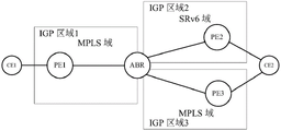
As shown in fig. 6, CE1 and CE2 belonging to the same L3VPN customer need to communicate across IGP area1, IGP area2 and IGP area3, both IGP area1 and IGP area2 have upgraded support SRv6 capability, but IGP area3 still only supports MPLS. Both CE1 and CE2 are IPv4 customers, CE2 is dually homed to PE2 and PE 3. In this application example, it is assumed that PE1 and PE2 allocate end.dxp 4 types to CE1 and CE2 customers, respectively, and route the advertisement with VPNv 4. Similar to the previous application example, such as PE1 assigning an end.dxp 4 type VPN SID (denoted SID _ dx4_ CE1) to CE1 customers, the SRv6SID resource pool maintained is denoted as prefix _ srv6_ SID _ pool _ PE1 and flooded within IGP area 1; PE2 assigns a VPN SID of the END.DX4 type (denoted as SID _ dx4_ CE2) to CE2 customers, and maintains a SRv6SID resource pool denoted as prefix _ srv6_ SID _ pool _ PE2 and flooded within IGP area 2.
The process flow of this application example is similar to the aforementioned application example, except that ECMP (or FRR) forwarding information is included in the local SID forwarding entry maintained for the VPN SID on the ABR node. The steps are briefly described as follows:
step 701, PE2 advertises vpnv4_ prefix _ ce2 to ABR through MP-IBGP, carrying sid _ dx4_ ce2 in BGP advertisement message; the PE2 maintains a corresponding local SID forwarding table entry for SID _ dx4_ ce 2.
Step 702, PE3 advertises vpnv4_ prefix _ ce2 to ABR through MP-IBGP, and carries label _ ce2 in BGP advertisement message; PE3 maintains a corresponding ILM entry for label _ ce 2.
In step 703, the ABR is configured to open the capability of allocating a VPN SID, and when the ABR receives a VPNv4 route (i.e., VPNv4_ prefix _ ce2) advertised by PE2 or PE3, the ABR locally allocates a VPN SID (denoted as SID _ br _100) to the VPNv4_ prefix _ ce 2. The SRv6SID resource pool maintained by the ABR is denoted as prefix _ srv6_ SID _ pool _ ABR and is flooded to the IGP area to which the ABR belongs through IGP.
The FUNCTION of the local SID forwarding entry maintained by ABR for SID _ br _100 is to exchange an incoming SRv6SID into an outgoing SRv6SID or MPLS label, where the entry includes two outgoing member forwarding information: one is BGP next hop PE2 and its associated sid _ dx4_ ce 2; the other is the BGP next hop PE3 and its associated label _ ce 2. These two outbound forwarding messages may form an ECMP or FRR.
In addition, ABR can learn prefix _ srv6_ sid _ pool _ PE2 through IGP flooding. .
ABR continues to advertise vpnv4_ prefix _ ce2 to PE1 through MP-IBGP, carrying sid _ br _100 in BGP advertisement messages.
In step 704, after receiving the VPNv4 route advertised by the ABR (i.e., VPNv4_ prefix _ ce2), the PE1 establishes a private network routing table entry prefix _ ce2, where the table entry only includes a BGP next hop ABR and its related sid _ br _ 100.
In addition, PE1 learns prefix _ srv6_ sid _ pool _ abr through IGP flooding.
Step 705, when the CE1 accesses the IPv4 packet of the CE2 and reaches the PE1, the destination address in the outer IPv6 header and the IPv6 header may be directly set to sid _ br _100, and the packet is forwarded to the ABR along the IGP shortest path (or TE path).
Step 706, when the IPv6 packet reaches the ABR, searching and hitting a corresponding local SID forwarding entry in the public network routing table according to the destination IP address (SID _ br _100) of the packet, and because the FUNCTION of the local SID forwarding entry is to exchange an incoming SRv6SID into an outgoing SRv6SID or MPLS label, and the entry includes two outgoing member forwarding information: if the destination IP address of the IPv6 message is modified to sid _ dx4_ ce2 when the message is forwarded to the first member, the routing table is searched and forwarded to the PE2 along the IGP shortest path (or TE path); if the IPv6 header is removed and MPLS encapsulation is carried out again when forwarding is carried out to the second member, a label _ ce2 is pressed and then a public network tunnel is traversed to the PE 3.
And 707, after the IPv6 message reaches the PE2, searching and hitting a local SID forwarding entry related to the SID _ dx _ CE2, decapsulating the IPv6 header, and forwarding the packet to the CE 2.
In step 708, after the MPLS packet reaches PE3, the ILM entry related to label _ CE2 is searched and hit, and the top label _ CE2 is popped off and then forwarded to CE 2.
Application example five
The present application example is substantially the same as application example four, and as shown in fig. 7, only IGP area2 has been upgraded to support SRv6 capability, but IGP area1 and IGP area3 still only support MPLS. This application example differs from other application examples in that ECMP (or FRR) forwarding information is contained in ILM entries maintained on the ABR nodes. The steps are briefly described as follows:
step 801, PE2 advertises vpnv4_ prefix _ ce2 to ABR through MP-IBGP, carrying sid _ dx4_ ce2 in BGP advertisement message; the PE2 maintains a corresponding local SID forwarding entry for SID _ dx4_ ce 2.
Step 802, PE3 advertises vpnv4_ prefix _ ce2 to ABR through MP-IBGP, and carries label _ ce2 in BGP advertisement message; PE3 maintains a corresponding ILM entry for label _ ce 2.
Step 803, the ABR is configured to open the capability of allocating VPN SID, and after receiving the VPNv4 route (i.e. VPNv4_ prefix _ ce2) advertised by PE2 or PE3, the ABR locally allocates a VPN SID for VPNv4_ prefix _ ce 2. In addition, the ABR also has MPLS capability, and it can also allocate a VPN label (denoted as label _ br _100) to vpnv4_ prefix _ ce 2.
The label operation of the ILM entry maintained by ABR for label _ br _100 is to exchange an ingress MPLS label into an egress SRv6SID or MPLS label, where the entry includes two egress member forwarding information: one is BGP next hop PE2 and its associated sid _ dx4_ ce 2; the other is the BGP next hop PE3 and its associated label _ ce 2. These two outbound forwarding messages may form an ECMP or FRR.
In addition, ABR can learn prefix _ srv6_ sid _ pool _ PE2 through IGP flooding. .
ABR continues to advertise vpnv4_ prefix _ ce2 to PE1 through MP-IBGP, carrying label _ br _100 in BGP advertisement messages.
In step 804, after receiving the VPNv4 route (i.e., VPNv4_ prefix _ ce2) advertised by the ABR, the PE1 establishes a private network routing table entry prefix _ ce2, where the table entry only includes one BGP next hop ABR and its related label _ br _ 100.
Step 805, when the CE1 accesses the IPv4 packet of the CE2 and reaches the PE1, encapsulates the MPLS label stack, where the bottom label is label _ br _100, and traverses the public network tunnel to the ABR.
Step 806, when the packet reaches the ABR, the public network tunnel is terminated, and according to the packet top label _ br _100, the corresponding ILM entry is searched and hit, because the label operation of the ILM entry is to exchange the incoming MPLS label into the outgoing SRv6SID or MPLS label, and the entry includes two outgoing member forwarding information, then: if the forwarding is carried out to the first member, the label _ br _100 is popped up, then the IPv6 header is encapsulated again, the destination IP address of the IPv6 message is set as sid _ dx4_ ce2, and then the routing table is searched and forwarded to the PE2 along the IGP shortest path (or TE path); if forwarding to the second member, the label _ br _100 is switched to label _ ce2, and then traverses the public network tunnel to PE 3.
In step 807, after the IPv6 message reaches PE2, the local SID forwarding entry related to SID _ dx _ CE2 is searched and hit, and the IPv6 header is decapsulated and forwarded to CE 2.
Step 808, after the MPLS packet reaches PE3, searching and hitting the ILM entry related to label _ CE2, popping off the top label _ CE2, and then forwarding the label to CE 2.
Application example six
The present application example is cross-domain for EVPN, and is completely similar to the aforementioned cross-domain application example for L3VPN, except that the route types advertised by BGP are different, and the processing on ASBR (or ABR) nodes is completely similar.
For example, in fig. 4, which is a point-to-point cross-domain, CE1 and CE2 establish a point-to-point connection through PE1 and PE2, ASBR2 may receive an Ethernet Auto-discovery Route (Type-1) (Ethernet Auto discovery Route-Type 1) Route advertisement from PE2 and include a valid SRv6VPN SID (e.g., using the FUNCTION as end. dx2, denoted as SID _ dx2_ PE2), ASBR2 is configured with the capability of assigning a VPN SID, and may reassign a new VPN SID (denoted as SID _ dx2_ ASBR2) for the VPN Route, ASBR2 continues to advertise the ASBR1 and modifies the next hop to itself, where the newly assigned VPN (SID _ dx2_ ASBR2) includes ASBR 2. Similarly, ASBR1 is also configured with the capability of assigning a VPN SID, and reassigns a new VPN SID (denoted as SID _ dx2_ ASBR1) to the VPN route received from ASBR2, and ASBR1 continues to advertise the VPN route to PE1 and modify the next hop to itself, including the newly assigned VPN SID (SID _ dx2_ ASBR1) for ASBR 1. The FUNCTIONs of the local SID forwarding entries created for the newly allocated VPN SIDs on ASBR1 and ASBR2 are both the inbound SRv6SID exchanged to the outbound SRv6SID or MPLS label. When a subsequent message from CE1 to CE2 is forwarded, the ASBR1 receives the IPv6 message, and the destination IP of the IPv6 message is SID _ dx2_ ASBR1, and hits the corresponding local SID forwarding entry, and the ASBR1 then switches the destination IP of the IPv6 message to SID _ dx2_ ASBR2, and continues to forward the message to the ASBR 2; similarly, after receiving the message, the ASBR2 exchanges the destination IP of the message to sid _ dx2_ PE2, and continues to forward the message to the PE2 along the shortest path (or TE path). The detailed description of the process is omitted.
Such as in fig. 6, which is a point-to-multipoint cross-domain, ABR may receive MAC/IP Advertisement Route (Type-2) (MAC/IP publish Route-Type 2) Route Advertisement from PE2 and have a valid SRv6VPN SID contained therein, the ABR may also receive from PE3 a MAC/IP Advertisement Route (Type-2) Route Advertisement with the same NLRI (Network Layer availability Information) key and including a valid MPLS label, then, the ABR may locally allocate a corresponding VPN SID or VPN label, create a corresponding local SID forwarding entry or ILM entry, where the entry includes two outgoing member forwarding information forming an ECMP (or FRR), at this time, the FUNCTION of the corresponding local SID is to switch an incoming SRv6SID into an outgoing SRv6SID or MPLS label, and the label operation of the corresponding ILM is to switch an incoming MPLS label into an outgoing SRv6SID or MPLS label. The detailed description of the process is omitted.
In addition, the EVPN also defines an IP prefix route (Type-5) (IP prefix route-Type 5) to support the L3VPN service, and at this time, the cross-domain scheme according to the embodiment of the present invention may also be used, which is not described in detail.
Application example seven
A conventional L2VPN in a PW (Pseudo-Wire) establishment manner, for example, RFC4761 defines a BGP VPLS NLRI routing type for advertising a label related to a PW. Although current draft-dawra-idr-srv6-vpn-02 does not describe how to extend RFC4761 to support the carrying of SRv6 SIDs in a BGP VPLS (Virtual Private LAN service) NLRI, such an extension is fully feasible. When the BGP VPLS NLRI can also support carrying SRv6SID information, the cross-domain scheme described in the embodiment of the present invention may also be applied, and compared with the foregoing application example, except that the advertised routing type is different, the other steps are completely similar, and are not described again.
As shown in fig. 8, an embodiment of the present invention further provides a border node, where the border node supports IPv6 segment routing SRv6 capability, and includes:
a processor 81;
a memory 82 for storing the processor-executable instructions;
a transmission means 83 for performing information transmission/reception communication according to the control of the processor;
wherein the processor 81 is configured to perform the following operations:
controlling the transmission device 82 to receive an announcement message which is sent by a first node to a second node and carries VPN routing information; wherein the first node and the second node belong to different domains respectively;
distributing VPN identification information to a VPN route corresponding to the VPN route information, carrying the VPN identification information in the notification message, and sending the notification message to the second node; wherein the VPN identification information includes at least one of a VPN Segment Identification (SID) and a VPN label.
The embodiment of the present invention further provides a computer-readable storage medium, which stores computer-executable instructions, where the computer-executable instructions are used to execute the VPN cross-domain implementation method.
It will be understood by those of ordinary skill in the art that all or some of the steps of the methods, systems, functional modules/units in the devices disclosed above may be implemented as software, firmware, hardware, and suitable combinations thereof. In a hardware implementation, the division between functional modules/units mentioned in the above description does not necessarily correspond to the division of physical components; for example, one physical component may have multiple functions, or one function or step may be performed by several physical components in cooperation. Some or all of the components may be implemented as software executed by a processor, such as a digital signal processor or microprocessor, or as hardware, or as an integrated circuit, such as an application specific integrated circuit. Such software may be distributed on computer readable media, which may include computer storage media (or non-transitory media) and communication media (or transitory media). The term computer storage media includes volatile and nonvolatile, removable and non-removable media implemented in any method or technology for storage of information such as computer readable instructions, data structures, program modules or other data, as is well known to those skilled in the art. Computer storage media includes, but is not limited to, RAM, ROM, EEPROM, flash memory or other memory technology, CD-ROM, Digital Versatile Disks (DVD) or other optical disk storage, magnetic cassettes, magnetic tape, magnetic disk storage or other magnetic storage devices, or any other medium which can be used to store the desired information and which can accessed by a computer. In addition, communication media typically embodies computer readable instructions, data structures, program modules or other data in a modulated data signal such as a carrier wave or other transport mechanism and includes any information delivery media as known to those skilled in the art.
Claims (26)
Priority Applications (4)
| Application Number | Priority Date | Filing Date | Title |
|---|---|---|---|
| CN201810893131.5A CN110830352B (en) | 2018-08-07 | 2018-08-07 | Method and device for realizing VPN cross-domain and boundary node |
| EP19846514.8A EP3836490B1 (en) | 2018-08-07 | 2019-08-06 | Vpn cross-domain implementation method, device, and border node |
| US17/264,976 US11936552B2 (en) | 2018-08-07 | 2019-08-06 | Method and device for implementing VPN cross-domain, and border node |
| PCT/CN2019/099512 WO2020029976A1 (en) | 2018-08-07 | 2019-08-06 | Vpn cross-domain implementation method, device, and border node |
Applications Claiming Priority (1)
| Application Number | Priority Date | Filing Date | Title |
|---|---|---|---|
| CN201810893131.5A CN110830352B (en) | 2018-08-07 | 2018-08-07 | Method and device for realizing VPN cross-domain and boundary node |
Publications (2)
| Publication Number | Publication Date |
|---|---|
| CN110830352A CN110830352A (en) | 2020-02-21 |
| CN110830352B true CN110830352B (en) | 2022-09-23 |
Family
ID=69413412
Family Applications (1)
| Application Number | Title | Priority Date | Filing Date |
|---|---|---|---|
| CN201810893131.5A Active CN110830352B (en) | 2018-08-07 | 2018-08-07 | Method and device for realizing VPN cross-domain and boundary node |
Country Status (4)
| Country | Link |
|---|---|
| US (1) | US11936552B2 (en) |
| EP (1) | EP3836490B1 (en) |
| CN (1) | CN110830352B (en) |
| WO (1) | WO2020029976A1 (en) |
Families Citing this family (38)
| Publication number | Priority date | Publication date | Assignee | Title |
|---|---|---|---|---|
| US11012350B2 (en) * | 2019-07-16 | 2021-05-18 | Cisco Technology, Inc. | Network interworking with no cross-domain state |
| CN113364683B (en) * | 2020-03-05 | 2022-12-30 | 华为技术有限公司 | Route sending method and equipment |
| CN113438160B (en) * | 2020-03-23 | 2024-05-31 | 中兴通讯股份有限公司 | Routing method, routing device and computer readable storage medium |
| US11233733B2 (en) * | 2020-03-26 | 2022-01-25 | Verizon Patent And Licensing Inc. | Systems and methods for SR-MPLS to SRv6 interworking |
| CN112511995B (en) * | 2020-03-30 | 2024-04-26 | 中兴通讯股份有限公司 | Message interaction method, device, equipment and storage medium |
| CN111464439B (en) * | 2020-03-31 | 2022-04-01 | 新华三信息安全技术有限公司 | Segment identifier issuing method and device |
| CN112511424B (en) * | 2020-05-15 | 2024-11-19 | 中兴通讯股份有限公司 | Method for forwarding and forwarding messages, head node, forwarding node, storage medium |
| CN113765789B (en) * | 2020-06-04 | 2025-01-28 | 中兴通讯股份有限公司 | Information processing method, node and computer readable storage medium |
| CN115699697B (en) * | 2020-06-16 | 2025-07-11 | 华为技术有限公司 | Segment Routing Point-to-Multipoint Paths |
| CN112511418B (en) | 2020-06-22 | 2025-04-29 | 中兴通讯股份有限公司 | Message indication method, device, equipment and storage medium |
| CN114157531A (en) * | 2020-08-18 | 2022-03-08 | 华为技术有限公司 | Method, device and network equipment for transmitting segment identification VPN SID of virtual private network |
| EP4191964A4 (en) * | 2020-08-18 | 2024-02-21 | Huawei Technologies Co., Ltd. | VIRTUAL PRIVATE NETWORK SEGMENT IDENTIFICATION (VPN SID) TRANSMISSION METHOD AND DEVICE, AND NETWORK DEVICE |
| CN114124776B (en) * | 2020-08-25 | 2025-07-15 | 中兴通讯股份有限公司 | Information processing method, network controller, node and computer readable storage medium |
| CN112511423B (en) * | 2020-09-03 | 2025-04-22 | 中兴通讯股份有限公司 | Message processing method, edge device and computer readable medium |
| CN119728517A (en) * | 2020-09-30 | 2025-03-28 | 华为技术有限公司 | A routing processing method and network device |
| US11611506B2 (en) * | 2020-10-09 | 2023-03-21 | Juniper Networks, Inc. | Processing a flow at the egress node in segment routing |
| CN114567544A (en) * | 2020-11-27 | 2022-05-31 | 华为技术有限公司 | Route notification method, device and system |
| CN114650248B (en) * | 2020-12-02 | 2023-07-18 | 中国电信股份有限公司 | Processing method and system of routing information and autonomous system boundary router |
| CN114650256A (en) * | 2020-12-17 | 2022-06-21 | 中兴通讯股份有限公司 | Message processing method, node and computer readable storage medium |
| CN115102900A (en) * | 2021-03-05 | 2022-09-23 | 中兴通讯股份有限公司 | Message forwarding method, system, storage medium and electronic device |
| CN115118659B (en) * | 2021-03-19 | 2025-09-19 | 华为技术有限公司 | Flow control method and related equipment |
| WO2022193896A1 (en) * | 2021-03-19 | 2022-09-22 | 华为技术有限公司 | Traffic control method and related device |
| CN115225427B (en) * | 2021-04-20 | 2024-05-17 | 华为技术有限公司 | Method and device for transmitting data message |
| CN115589382B (en) * | 2021-06-23 | 2026-03-31 | 华为技术有限公司 | A method and related equipment for message transmission |
| CN115550252A (en) * | 2021-06-29 | 2022-12-30 | 华为技术有限公司 | Method, device, equipment and storage medium for routing, publishing and forwarding messages |
| CN113872866B (en) * | 2021-09-28 | 2023-04-07 | 中国电信股份有限公司 | Message forwarding method, system and storage medium |
| CN115914094A (en) * | 2021-09-30 | 2023-04-04 | 华为技术有限公司 | A route publishing method, message forwarding method, device and system |
| CN115914093A (en) * | 2021-09-30 | 2023-04-04 | 中兴通讯股份有限公司 | Method for assigning virtual private network service identifier, message processing method and device |
| CN113992558B (en) * | 2021-10-26 | 2023-04-18 | 新华三信息安全技术有限公司 | Method, device, electronic equipment and medium for route publishing |
| CN116112416A (en) * | 2021-11-11 | 2023-05-12 | 中兴通讯股份有限公司 | Message forwarding method, electronic device and storage medium |
| CN114205187B (en) * | 2021-12-02 | 2023-08-08 | 中盈优创资讯科技有限公司 | End-to-end path calculation method and device suitable for MPLS-VPN of OptionC cross-domain |
| CN116264589A (en) * | 2021-12-13 | 2023-06-16 | 华为技术有限公司 | A message transmission method and device |
| CN114389996B (en) * | 2022-01-04 | 2023-06-09 | 烽火通信科技股份有限公司 | Method and device for SRv SID distribution in multi-topology environment based on resources |
| CN114513388B (en) * | 2022-01-17 | 2023-09-15 | 新华三技术有限公司 | Route updating method and device |
| CN114448881B (en) * | 2022-02-25 | 2023-06-09 | 烽火通信科技股份有限公司 | Method and system for inter-operating communication of cross-SR MPLS and SRV6 domains |
| US11575596B1 (en) * | 2022-03-07 | 2023-02-07 | Ciena Corporation | Identifying an ingress router of a flow in inter-AS VPN option-C networks with visibility in one AS |
| CN114679405B (en) * | 2022-04-12 | 2023-07-25 | 烽火通信科技股份有限公司 | SRv6 message forwarding method, storage medium, electronic equipment and device |
| CN115412512B (en) * | 2022-10-31 | 2023-03-24 | 浙江九州云信息科技有限公司 | IPv 6-based multi-cloud cross-network intercommunication method and device |
Family Cites Families (8)
| Publication number | Priority date | Publication date | Assignee | Title |
|---|---|---|---|---|
| CN100563194C (en) * | 2006-11-02 | 2009-11-25 | 杭州华三通信技术有限公司 | How to establish an LSP |
| ITRM20130571A1 (en) * | 2013-10-17 | 2015-04-18 | Cisco Tech Inc | PROTECTION OF A SCALABLE EDGE NODE USING SEGMENT ROUNDING |
| US9912577B2 (en) * | 2014-04-17 | 2018-03-06 | Cisco Technology, Inc. | Segment routing—egress peer engineering (SP-EPE) |
| CN105323176A (en) * | 2014-06-20 | 2016-02-10 | 中兴通讯股份有限公司 | Method and apparatus for publishing address information |
| US10412019B2 (en) * | 2015-07-06 | 2019-09-10 | Futurewei Technologies, Inc. | Path computation element central controllers (PCECCs) for network services |
| CN111682959B (en) * | 2015-11-24 | 2023-09-15 | 华为技术有限公司 | A method for determining mapping servers, routing nodes and autonomous systems |
| CN108702328B (en) | 2016-02-15 | 2021-04-09 | 瑞典爱立信有限公司 | IS-IS extension for flexible path splicing and selection for traffic traversing segment routing and MPLS networks |
| US10506083B2 (en) * | 2017-06-27 | 2019-12-10 | Cisco Technology, Inc. | Segment routing gateway storing segment routing encapsulating header used in encapsulating and forwarding of returned native packet |
-
2018
- 2018-08-07 CN CN201810893131.5A patent/CN110830352B/en active Active
-
2019
- 2019-08-06 US US17/264,976 patent/US11936552B2/en active Active
- 2019-08-06 WO PCT/CN2019/099512 patent/WO2020029976A1/en not_active Ceased
- 2019-08-06 EP EP19846514.8A patent/EP3836490B1/en active Active
Non-Patent Citations (2)
| Title |
|---|
| BGP Signaling of IPv6-Segment-Routing-based VPN Networks draft-dawra-idr-srv6-vpn-01.txt;G.Dawra et al;《IETF》;20170911;第3-4页,第3,3.1节 * |
| Segment Routing Architecture;C.Filsfils et al;《IETF》;20180731;第18-19页,图4 * |
Also Published As
| Publication number | Publication date |
|---|---|
| EP3836490A4 (en) | 2021-10-27 |
| WO2020029976A1 (en) | 2020-02-13 |
| EP3836490B1 (en) | 2024-04-03 |
| CN110830352A (en) | 2020-02-21 |
| EP3836490A1 (en) | 2021-06-16 |
| US20210328906A1 (en) | 2021-10-21 |
| US11936552B2 (en) | 2024-03-19 |
Similar Documents
| Publication | Publication Date | Title |
|---|---|---|
| CN110830352B (en) | Method and device for realizing VPN cross-domain and boundary node | |
| EP3832957B1 (en) | Transmission control method, node, network system, and storage medium | |
| US11689452B2 (en) | Method for forwarding service data, network device, and network system | |
| US10484203B2 (en) | Method for implementing communication between NVO3 network and MPLS network, and apparatus | |
| US8750301B2 (en) | Method, device for implementing identifier and locator split, and method for data encapsulating | |
| WO2020156105A1 (en) | Data forwarding method and related device | |
| US20210273881A1 (en) | Message Sending Method, Binding Relationship Advertising Method, Apparatus, and Storage Medium | |
| CN102469010B (en) | A kind of method and network equipment distributing MPLS label | |
| WO2019205836A1 (en) | Data packet forwarding method and apparatus | |
| CN113726653B (en) | Message processing method and device | |
| CN108156067A (en) | It is a kind of to realize the method and system based on Ethernet Virtual Private Network | |
| WO2021017590A1 (en) | Method, system, and first gw for achieving dci three-layer communication | |
| US7525949B1 (en) | Forwarding for network devices | |
| WO2023051179A1 (en) | Method and apparatus for receiving border gateway protocol routing, method and apparatus for sending border gateway protocol routing, and storage medium | |
| Radhakrishnan et al. | Egress Engineering over BGP Label Unicast in MPLS-based Networks | |
| CN120017581A (en) | Routing publishing method, message transmission method, communication device, and communication system | |
| CN119728538A (en) | A routing notification, message transmission method and device | |
| Palislamovic et al. | RFC 8388: Usage and Applicability of BGP MPLS-Based Ethernet VPN |
Legal Events
| Date | Code | Title | Description |
|---|---|---|---|
| PB01 | Publication | ||
| PB01 | Publication | ||
| SE01 | Entry into force of request for substantive examination | ||
| SE01 | Entry into force of request for substantive examination | ||
| GR01 | Patent grant | ||
| GR01 | Patent grant |