CN102116943B - Thermotropic display element and thermotropic display device - Google Patents
Thermotropic display element and thermotropic display device Download PDFInfo
- Publication number
- CN102116943B CN102116943B CN200910239664.2A CN200910239664A CN102116943B CN 102116943 B CN102116943 B CN 102116943B CN 200910239664 A CN200910239664 A CN 200910239664A CN 102116943 B CN102116943 B CN 102116943B
- Authority
- CN
- China
- Prior art keywords
- heating element
- space
- material layer
- thermotropic display
- display element
- Prior art date
- Legal status (The legal status is an assumption and is not a legal conclusion. Google has not performed a legal analysis and makes no representation as to the accuracy of the status listed.)
- Expired - Fee Related
Links
Images


Classifications
-
- G—PHYSICS
- G02—OPTICS
- G02F—OPTICAL DEVICES OR ARRANGEMENTS FOR THE CONTROL OF LIGHT BY MODIFICATION OF THE OPTICAL PROPERTIES OF THE MEDIA OF THE ELEMENTS INVOLVED THEREIN; NON-LINEAR OPTICS; FREQUENCY-CHANGING OF LIGHT; OPTICAL LOGIC ELEMENTS; OPTICAL ANALOGUE/DIGITAL CONVERTERS
- G02F1/00—Devices or arrangements for the control of the intensity, colour, phase, polarisation or direction of light arriving from an independent light source, e.g. switching, gating or modulating; Non-linear optics
- G02F1/01—Devices or arrangements for the control of the intensity, colour, phase, polarisation or direction of light arriving from an independent light source, e.g. switching, gating or modulating; Non-linear optics for the control of the intensity, phase, polarisation or colour
- G02F1/17—Devices or arrangements for the control of the intensity, colour, phase, polarisation or direction of light arriving from an independent light source, e.g. switching, gating or modulating; Non-linear optics for the control of the intensity, phase, polarisation or colour based on variable-absorption elements not provided for in groups G02F1/015 - G02F1/169
-
- G—PHYSICS
- G02—OPTICS
- G02F—OPTICAL DEVICES OR ARRANGEMENTS FOR THE CONTROL OF LIGHT BY MODIFICATION OF THE OPTICAL PROPERTIES OF THE MEDIA OF THE ELEMENTS INVOLVED THEREIN; NON-LINEAR OPTICS; FREQUENCY-CHANGING OF LIGHT; OPTICAL LOGIC ELEMENTS; OPTICAL ANALOGUE/DIGITAL CONVERTERS
- G02F1/00—Devices or arrangements for the control of the intensity, colour, phase, polarisation or direction of light arriving from an independent light source, e.g. switching, gating or modulating; Non-linear optics
- G02F1/0009—Materials therefor
- G02F1/009—Thermal properties
-
- G—PHYSICS
- G02—OPTICS
- G02F—OPTICAL DEVICES OR ARRANGEMENTS FOR THE CONTROL OF LIGHT BY MODIFICATION OF THE OPTICAL PROPERTIES OF THE MEDIA OF THE ELEMENTS INVOLVED THEREIN; NON-LINEAR OPTICS; FREQUENCY-CHANGING OF LIGHT; OPTICAL LOGIC ELEMENTS; OPTICAL ANALOGUE/DIGITAL CONVERTERS
- G02F1/00—Devices or arrangements for the control of the intensity, colour, phase, polarisation or direction of light arriving from an independent light source, e.g. switching, gating or modulating; Non-linear optics
- G02F1/01—Devices or arrangements for the control of the intensity, colour, phase, polarisation or direction of light arriving from an independent light source, e.g. switching, gating or modulating; Non-linear optics for the control of the intensity, phase, polarisation or colour
- G02F1/0147—Devices or arrangements for the control of the intensity, colour, phase, polarisation or direction of light arriving from an independent light source, e.g. switching, gating or modulating; Non-linear optics for the control of the intensity, phase, polarisation or colour based on thermo-optic effects
Landscapes
- Physics & Mathematics (AREA)
- Nonlinear Science (AREA)
- General Physics & Mathematics (AREA)
- Optics & Photonics (AREA)
- Devices For Indicating Variable Information By Combining Individual Elements (AREA)
- Electrochromic Elements, Electrophoresis, Or Variable Reflection Or Absorption Elements (AREA)
Abstract
Description
技术领域 technical field
本发明涉及一种热致显示元件及使用该热致显示元件的热致显示装置。The invention relates to a thermotropic display element and a thermotropic display device using the thermotropic display element.
背景技术 Background technique
目前,电子纸是一种比较常用的不需要背光源的显示装置。电子纸是一种新型的信息载体,由于可以替代传统的纸张,在广告、报纸、图书等多种领域有着广泛的应用前景和巨大的商业价值。目前市场上出现的电子纸主要采用电泳显示技术。电泳显示技术包括微胶囊型电泳技术、微杯型电泳技术以及电子粉流体技术。Currently, electronic paper is a commonly used display device that does not require a backlight source. Electronic paper is a new type of information carrier. Since it can replace traditional paper, it has broad application prospects and great commercial value in various fields such as advertisements, newspapers, and books. The electronic papers currently on the market mainly use electrophoretic display technology. Electrophoretic display technology includes microcapsule electrophoresis technology, microcup electrophoresis technology and electronic powder fluid technology.
微胶囊型电泳技术是将黑、白两色的带电颗粒以及电泳介质封装于微囊化液滴结构中形成微胶囊,然后在每个微胶囊上下两端分别设置导电背板及透明导电层。通过导电背板及透明导电层对微胶囊施加电场来控制微胶囊中不同电荷黑白颗粒的升降移动,以呈现出黑白单色的显示效果。Microcapsule electrophoresis technology is to encapsulate black and white charged particles and electrophoretic medium in a microencapsulated droplet structure to form microcapsules, and then set a conductive backplane and a transparent conductive layer at the upper and lower ends of each microcapsule. The electric field is applied to the microcapsules through the conductive backplane and the transparent conductive layer to control the up and down movement of black and white particles with different charges in the microcapsules, so as to present a monochromatic display effect of black and white.
微杯型电泳技术是在有透明导电层的塑料薄膜上涂布压模液体,经连续式微压模制程产生微杯数组,填入电泳介质以及带正电的白色颗粒后,涂布密封液体再加以固化,然后再设置导电背板及透明导电层。通过供电给导电背板及透明导电层形成正负电场来驱动带正电的白色颗粒移动,形成眼睛所看到的图案。The microcup type electrophoresis technology is to apply a compression molding liquid on a plastic film with a transparent conductive layer. After a continuous microcompression molding process, a microcup array is produced. After filling the electrophoretic medium and positively charged white particles, the sealing liquid is coated again. After being cured, a conductive backplane and a transparent conductive layer are provided. By supplying power to the conductive backplane and transparent conductive layer to form a positive and negative electric field to drive the positively charged white particles to move, forming the pattern seen by the eyes.
电子粉流体技术是将电泳介质和带正负电荷的黑白两色粉末密封于具有电极的两底板之间。通过在具有电极的两底板之间施加电场,使分别带正负电荷的黑白两色粉末流动,以达到显示影像。Electronic powder fluid technology is to seal the electrophoretic medium and black and white powder with positive and negative charges between two bottom plates with electrodes. By applying an electric field between two bottom plates with electrodes, the positively and negatively charged black and white powders flow to display images.
然而,由于上述应用电泳显示技术的电子纸中均需要用到带电颗粒一般仅为白色和黑色两种,导致电子纸难以实现彩色显示。However, since the above-mentioned electronic paper using the electrophoretic display technology needs to use charged particles generally only in white and black, it is difficult for the electronic paper to realize color display.
发明内容 Contents of the invention
有鉴于此,确有必要提供一成本较低,可以实现彩色显示的热致显示元件及显示装置。In view of this, it is indeed necessary to provide a thermotropic display element and display device with lower cost and capable of realizing color display.
一种热致显示元件,其包括:一封闭壳体;一隔离层,该隔离层设置于该封闭壳体内,并将该封闭壳体分成第一空间和第二空间;一第一加热元件,该第一加热元件设置在封闭壳体上,用于加热第一空间;一第二加热元件,该第二加热元件设置在封闭壳体上,用于加热第二空间;一热致变色材料层,该热致变色材料层设置于第一空间内,该热致变色材料层用于在第一加热元件的作用下通过释放或吸收气体发生颜色变化;一吸附材料层,该吸附材料层设置于第二空间内,用于透过隔离层吸收所述热致变色材料释放的气体或第二加热元件的作用下释放气体。A thermal display element, comprising: a closed case; an isolation layer, which is arranged in the closed case and divides the closed case into a first space and a second space; a first heating element, The first heating element is arranged on the closed shell for heating the first space; a second heating element is set on the closed shell for heating the second space; a thermochromic material layer , the layer of thermochromic material is arranged in the first space, and the layer of thermochromic material is used to change color by releasing or absorbing gas under the action of the first heating element; an adsorption material layer is arranged in the The second space is used to absorb the gas released by the thermochromic material through the isolation layer or release the gas under the action of the second heating element.
一种热致显示装置,其包括:一第一电极板,该第一电极板包括多个第一行电极和多个第一列电极,该多个第一行电极和多个第一列电极交叉设置形成多个第一网格;一第二电极板,该第二电极板包括多个第二行电极和多个第二列电极,该多个第二行电极和多个第二列电极交叉设置形成多个第二网格,所述第二电极板与第一电极板相对设置,第一网格和第二网格一一对应;多个热致显示元件,该多个热致显示元件在该阵列中排列形成多个行和列,每个热致显示元件对应一第一网格和一第二网格。每个热致显示单元包括:一封闭壳体;一隔离层,该隔离层设置于该封闭壳体内,并将该封闭壳体分成第一空间和第二空间;一第一加热元件设置在该封闭壳体上靠近第一空间的一端;一第二加热元件设置在该封闭壳体上靠近第二空间的一端;一热致变色材料层,该热致变色材料层设置于第一空间内,该热致变色材料层用于在第一加热元件的作用下通过释放或吸收气体发生颜色变化;一吸附材料层,该吸附材料层设置于第二空间内。该吸附材料层用于透过隔离层吸收所述热致变色材料层释放的气体或在第二加热元件的作用下释放气体。每一行热致显示元件的第一加热元件分别与一第一行电极,每一列第一加热元件和一第一列电极电连接;每一行热致显示元件的第二加热元件分别与一第二行电极,每一列第二加热元件和一第二列电极电连接。A thermal display device, comprising: a first electrode plate, the first electrode plate includes a plurality of first row electrodes and a plurality of first column electrodes, the plurality of first row electrodes and a plurality of first column electrodes Intersect to form a plurality of first grids; a second electrode plate, the second electrode plate includes a plurality of second row electrodes and a plurality of second column electrodes, the plurality of second row electrodes and a plurality of second column electrodes The cross arrangement forms a plurality of second grids, the second electrode plates are arranged opposite to the first electrode plates, and the first grids correspond to the second grids one by one; a plurality of thermotropic display elements, the plurality of thermotropic display elements The elements are arranged in the array to form a plurality of rows and columns, and each thermotropic display element corresponds to a first grid and a second grid. Each thermal display unit includes: a closed casing; an insulating layer, which is arranged in the closed casing and divides the closed casing into a first space and a second space; a first heating element is arranged in the closed casing One end of the closed shell close to the first space; a second heating element is arranged on the closed shell close to the end of the second space; a layer of thermochromic material, the layer of thermochromic material is set in the first space, The thermochromic material layer is used to change color by releasing or absorbing gas under the action of the first heating element; an adsorption material layer is arranged in the second space. The adsorption material layer is used to absorb the gas released by the thermochromic material layer through the isolation layer or release the gas under the action of the second heating element. The first heating elements of each row of thermotropic display elements are respectively connected to a first row electrode, and the first heating elements of each column are electrically connected to a first column electrode; the second heating elements of each row of thermotropic display elements are respectively connected to a second row electrode. The row electrodes, each column of second heating elements are electrically connected to a second column electrode.
与现有技术相比较,所述的热致显示元件和热致显示装置中,通过第一加热元件加热第一空间使该第一空间内的热致变色材料层失水产生气体发生颜色变化;该热致变色材料产生的气体穿过隔离层被第二空间的吸附材料层吸收,通过第二加热元件加热该吸附材料层,使吸附材料层吸附的物质蒸发之后穿过隔离层到达第一空间,使热致变色材料层得水复原成原色,从而实现该热致显示元件和热致显示装置的显示效果。所述的热致显示元件和热致显示装置中的热致显色材料层的颜色变化较多,可以实现热致显示装置的彩色显示。Compared with the prior art, in the thermotropic display element and the thermotropic display device, the first space is heated by the first heating element so that the thermochromic material layer in the first space loses water and produces a color change of the gas; The gas generated by the thermochromic material passes through the isolation layer and is absorbed by the adsorption material layer in the second space, and the adsorption material layer is heated by the second heating element, so that the substance adsorbed by the adsorption material layer evaporates and then passes through the isolation layer to reach the first space to restore the water in the thermochromic material layer to the original color, so as to realize the display effect of the thermochromic display element and thermotropic display device. The color of the thermochromic material layer in the thermotropic display element and the thermotropic display device changes more, and the color display of the thermotropic display device can be realized.
附图说明 Description of drawings
图1为本发明第一实施例的热致显示元件的俯视示意图。FIG. 1 is a schematic top view of a thermotropic display element according to a first embodiment of the present invention.
图2为本发明第一实施例的热致显示元件的侧面剖视图。FIG. 2 is a side cross-sectional view of the thermal display element according to the first embodiment of the present invention.
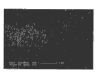
图3为本发明第一实施例的热致显示元件中用作加热元件的碳纳米管拉膜的扫描电镜照片。FIG. 3 is a scanning electron micrograph of a drawn carbon nanotube film used as a heating element in the thermotropic display element according to the first embodiment of the present invention.
图4为本发明第一实施例的热致显示元件中用作加热元件的碳纳米管絮化膜的扫描电镜照片。FIG. 4 is a scanning electron micrograph of a carbon nanotube flocculation film used as a heating element in the thermotropic display element according to the first embodiment of the present invention.
图5为本发明第一实施例的热致显示元件中用作加热元件的碳纳米管碾压膜的扫描电镜照片。5 is a scanning electron micrograph of a carbon nanotube laminated film used as a heating element in the thermotropic display element according to the first embodiment of the present invention.
图6为本发明第二实施例的热致显示元件的侧视剖面示意图。FIG. 6 is a schematic cross-sectional side view of a thermotropic display element according to a second embodiment of the present invention.
图7为本发明第三实施例的热致显示元件的侧视剖面示意图。FIG. 7 is a schematic cross-sectional side view of a thermotropic display element according to a third embodiment of the present invention.
图8为本发明第四实施例的热致显示装置的侧视示意图。FIG. 8 is a schematic side view of a thermotropic display device according to a fourth embodiment of the present invention.
图9为图8热致显示装置中第一电极板的俯视示意图。FIG. 9 is a schematic top view of the first electrode plate in the thermotropic display device of FIG. 8 .
图10为图8热致显示装置中第二电极板的俯视示意图。FIG. 10 is a schematic top view of the second electrode plate in the thermotropic display device of FIG. 8 .
主要元件符号说明Description of main component symbols


具体实施方式 Detailed ways
以下将结合附图对本发明的热致显示元件和热致显示装置作进一步的详细说明。The thermotropic display element and thermotropic display device of the present invention will be further described in detail below with reference to the accompanying drawings.
请参阅图1及图2,本发明第一实施例提供一种热致显示元件100,该热致显示元件100包括一封闭壳体102;一隔离层104,该隔离层104设置于该封闭壳体102内,并将该封闭壳体102分成第一空间120和第二空间122;一第一加热元件106,该第一加热元件106用于加热第一空间120;一第二加热元件108,该第二加热元件108用于加热第二空间122;一热致变色材料层110,该热致变色材料层110设置于第一空间120内,该热致变色材料层110在一固定温度下产生水蒸汽发生颜色变化;一吸附材料层112,该吸附材料层112设置于第二空间122内。该热致显示元件进一步包括至少两个第一电极114和至少两个第二电极116。该至少两个第一电极114分别与该第一加热元件106电连接,该至少两个第二电极116分别与该第二加热元件108电连接。Please refer to FIG. 1 and FIG. 2 , the first embodiment of the present invention provides a
所述封闭壳体102的形状不限,可以为立方体、长方体、三棱柱、圆柱体等结构。所述封闭壳体102由上基板、下基板和侧板封装形成。所述上基板、下基板或侧板的形状不限,可以为平面版状结构,也可以为弧状结构。本实施例中,所述封闭壳体102为一立方体结构,其包括一上基板1022及一下基板1024,该上基板1022和该下基板1024相对设置。该封闭壳体102进一步包括四个侧板1026,该四个侧板1026设置于上基板1022和下基板1024之间。所述上基板1022、下基板1024与四个侧板1026封装形成该封闭壳体102。所述上基板1022为一透明绝缘基板,其材料可以为玻璃或透明高分子材料。所述透明高分子材料包括聚苯二甲酸乙二醇酯(PET)、聚酰亚胺(PI)、聚苯乙烯(PS)、聚丙烯(PP)、聚乙烯(PE)、聚氯丁烯(PC)或聚氯乙烯(PVC)。所述下基板1024及四个侧板1026的材料为绝缘材料,可以为陶瓷、塑料、橡胶等。所述上基板1022和下基板1024的材料优选为耐高温的材料。The shape of the closed
所述隔离层104悬空设置于该封闭壳体102内。该隔离层104通过该侧板1026悬空设置。隔离层104的形状不限,只需确保隔离层104的外周缘与侧板1026连接,将封闭壳体102内部空间分成两部分可。该隔离层104的外周缘可通过粘结剂或者机械固定方式固定于侧板1026上,也可以镶嵌于该侧板1026上。优选地,所述隔离层104与上基板1022或/和下基板1024相互平行。本实施例中,所述隔离层104与上基板1022和下基板1024的形状相同,并平行于上基板1022和下基板1024,该隔离层104的外周缘分别通过粘结剂固定于四个侧板1026上。所述隔离层104具有多个微孔,以使第一空间120和第二空间122之间可以有气体通过。所述隔离层104可以为高分子材料制作形成的半透膜,如细胞壁、膀胱膜或羊皮纸等。该隔离层104还可以为一多孔基底的孔内沉积有其它材料形成的半透壁,如在无釉陶瓷的孔内沉积铁氰化铜颗粒形成的隔离层104。该隔离层104用于隔离第一空间120和第二空间122,使该第一空间120和第二空间122之间只能通过气体,不能通过液体或固体。隔离层104的厚度不限,优选为1微米~1毫米。本实施例中,所述隔离层104为厚度为100微米的羊皮纸。The
所述第一空间120由上基板1022、隔离层104和四个侧板1026围成。所述第二空间122由下基板1024、隔离层104和四个侧板1026围成。所述第一空间120和第二空间122分别位于隔离层104的两侧。第一空间120和第二空间122的大小和形状可以相同也可以不同。第一空间120的大小和形状由上基板1022与隔离层104之间的距离和侧板1026之间的距离。第二空间122的大小和形状由下基板1024与隔离层104之间的距离和侧板1026之间的距离决定。第一空间120和第二空间122的大小和形状可以相同也可以不同。本实施例中,第一空间120和第二空间122的大小和形状相同。The
所述热致变色材料层110在一固定温度下可产生气体。该热致变色材料层110的材料可以为含有内结晶水的铜(Cu)、钴(Co)或镍(Ni)等的无机盐类的热致变色材料,这类热致变色材料被加热到一固定温度时失去结晶水引起颜色变化。具体地,该热致变色材料层110的材料包括CuSO4·5H2O、NiCl2·C6H12N4·H2O、CoCl2·2C6H12N4·10H2O、CoBr2·2C6H12N4·10H2O、CoI2·2C6H12N4·10H2O、CoSO4·C6H12N4·9H2O、CuSO4·2C6H12N4·5H2O、NiBr2·2C6H12N4·10H2O、NiCl2·2C6H12N4·10H2O或Co(NO3)2·2C6H12N4·10H2O等。该热致变色材料还可以为变色硅胶。该热致变色材料层110填充于第一空间120内部,所述第一加热元件106用于加热该热致变色材料层110,使该热致变色材料层110在一固定温度下失水发生颜色变化,从而实现热致显示元件100的显示功能。The
所述吸附材料层112为吸水性或吸附性较强的材料,可以为聚炳烯酸酯、聚乙烯醇、醋酸乙烯共聚物、聚氨酯、聚环氧乙烷或淀粉接校共聚物等。可以理解,该吸附材料层112还可以为多孔性的吸附性较强的材料,如海绵或活性炭等。该吸附材料层112填充于第二空间122内,第二加热元件108用于加热该吸附材料层112。The
所述第一加热元件106可设置于上基板1022的内表面或外表面。本实施例中,第一加热元件106位于上基板1022的外表面,通过该上基板1022向第一空间120提供热量。本实施例所述第一加热元件106为一透明层状结构。所述第一加热元件106可以为一氧化铟锡(ITO)薄膜或一碳纳米管层状结构。所述第二加热元件108可设置于下基板1024的外表面或内表面。本实施例中,所述第二加热元件108设置于下基板1024的外表面,通过该下基板1024向第二空间122提供热量。该第二加热元件108为一层状结构,可以透明也可以不透明。所述第二加热元件108可以为一金属层、一ITO薄膜或一碳纳米管层状结构。The
所述碳纳米管层状结构包括至少一层碳纳米管膜。当碳纳米管层状结构包括至少两层碳纳米管膜时,该至少两层碳纳米管膜层叠设置或并排设置。所述碳纳米管膜包括均匀分布的碳纳米管,碳纳米管之间通过范德华力紧密结合。该碳纳米管膜中的碳纳米管为无序或有序排列。这里的无序排列指碳纳米管的排列方向无规律,这里的有序排列指至少多数碳纳米管的排列方向具有一定规律。具体地,当碳纳米管膜包括无序排列的碳纳米管时,碳纳米管相互缠绕或者各向同性排列;当碳纳米管层状结构包括有序排列的碳纳米管时,碳纳米管沿一个方向或者多个方向择优取向排列。本实施例中,优选地,所述碳纳米管层状结构包括多个层叠设置的碳纳米管膜,且该碳纳米管层状结构的厚度优选为0.5纳米~1毫米。优选地,该碳纳米管层状结构的厚度为100纳米~0.1毫米。可以理解,当碳纳米管层状结构的透明度与碳纳米管层状结构的厚度有关,当碳纳米管层状结构的厚度越小时,该碳纳米管层状结构的透光度越好。所述碳纳米管层状结构的单位面积热容小于2×10⁻⁴焦耳每平方厘米开尔文。优选地,所述碳纳米管层状结构的单位面积热容可以小于等于1.7×10⁻⁶焦耳每平方厘米开尔文。由于碳纳米管的热容较小,所以由该碳纳米管层状结构构成的加热元件具有较快的热响应速度,可用于对物体进行快速加热。可以理解,碳纳米管层状结构的热响应速度与其厚度有关。在相同面积的情况下,碳纳米管层状结构的厚度越大,热响应速度越慢;反之,碳纳米管层状结构的厚度越小,热响应速度越快。The carbon nanotube layered structure includes at least one layer of carbon nanotube film. When the carbon nanotube layered structure includes at least two layers of carbon nanotube films, the at least two layers of carbon nanotube films are stacked or arranged side by side. The carbon nanotube film includes uniformly distributed carbon nanotubes, and the carbon nanotubes are closely combined by van der Waals force. The carbon nanotubes in the carbon nanotube film are arranged in disorder or order. The disordered arrangement here means that the arrangement direction of the carbon nanotubes is irregular, and the ordered arrangement here means that the arrangement direction of at least most of the carbon nanotubes has certain rules. Specifically, when the carbon nanotube film includes carbon nanotubes arranged in disorder, the carbon nanotubes are intertwined or arranged isotropically; when the carbon nanotube layered structure includes carbon nanotubes arranged in order, the carbon nanotubes are arranged along the One direction or multiple directions are preferentially aligned. In this embodiment, preferably, the carbon nanotube layered structure includes a plurality of stacked carbon nanotube films, and the thickness of the carbon nanotube layered structure is preferably 0.5 nm to 1 mm. Preferably, the carbon nanotube layered structure has a thickness of 100 nanometers to 0.1 millimeters. It can be understood that when the transparency of the carbon nanotube layered structure is related to the thickness of the carbon nanotube layered structure, the smaller the thickness of the carbon nanotube layered structure, the better the light transmittance of the carbon nanotube layered structure. The heat capacity per unit area of the carbon nanotube layered structure is less than 2×10 -4 joules per square centimeter Kelvin. Preferably, the heat capacity per unit area of the carbon nanotube layered structure may be less than or equal to 1.7×10 -6 joules per square centimeter Kelvin. Due to the small heat capacity of the carbon nanotubes, the heating element composed of the carbon nanotube layered structure has a faster thermal response speed and can be used for rapid heating of objects. It can be understood that the thermal response speed of the carbon nanotube layered structure is related to its thickness. In the case of the same area, the larger the thickness of the carbon nanotube layered structure, the slower the thermal response speed; conversely, the smaller the thickness of the carbon nanotube layered structure, the faster the thermal response speed.
请参阅图3,所述碳纳米管膜可以为一碳纳米管拉膜。该碳纳米管拉膜为从碳纳米管阵列中直接拉取获得的一种碳纳米管膜。每一碳纳米管膜是由若干碳纳米管组成的自支撑结构。所述若干碳纳米管为基本沿同一方向择优取向排列。所述择优取向是指在碳纳米管膜中大多数碳纳米管的整体延伸方向基本朝同一方向。而且,所述大多数碳纳米管的整体延伸方向基本平行于碳纳米管膜的表面。进一步地,所述碳纳米管膜中多数碳纳米管是通过范德华力首尾相连。具体地,所述碳纳米管膜中基本朝同一方向延伸的大多数碳纳米管中每一碳纳米管与在延伸方向上相邻的碳纳米管通过范德华力首尾相连。当然,所述碳纳米管膜中存在少数随机排列的碳纳米管,这些碳纳米管不会对碳纳米管膜中大多数碳纳米管的整体取向排列构成明显影响。所述自支撑为碳纳米管膜不需要大面积的载体支撑,而只要相对两边提供支撑力即能整体上悬空而保持自身膜状状态,即将该碳纳米管膜置于(或固定于)间隔一固定距离设置的两个支撑体上时,位于两个支撑体之间的碳纳米管膜能够悬空保持自身膜状状态。所述自支撑主要通过碳纳米管膜中存在连续的通过范德华力首尾相连延伸排列的碳纳米管而实现。Please refer to FIG. 3 , the carbon nanotube film may be a carbon nanotube drawn film. The carbon nanotube film is a carbon nanotube film obtained by directly pulling from a carbon nanotube array. Each carbon nanotube film is a self-supporting structure composed of several carbon nanotubes. The plurality of carbon nanotubes are arranged in the preferred orientation basically along the same direction. The preferred orientation means that the overall extension direction of most carbon nanotubes in the carbon nanotube film basically faces the same direction. Also, the overall extension direction of the majority of carbon nanotubes is substantially parallel to the surface of the carbon nanotube film. Further, most of the carbon nanotubes in the carbon nanotube film are connected end to end by van der Waals force. Specifically, each carbon nanotube in the majority of carbon nanotubes extending in the same direction in the carbon nanotube film is connected end-to-end with the adjacent carbon nanotubes in the extending direction through van der Waals force. Of course, there are a small number of randomly arranged carbon nanotubes in the carbon nanotube film, and these carbon nanotubes will not significantly affect the overall alignment of most carbon nanotubes in the carbon nanotube film. The self-supporting carbon nanotube film does not require a large-area carrier support, but as long as the supporting force is provided on both sides, it can be suspended as a whole and maintain its own film state, that is, the carbon nanotube film is placed (or fixed) in the spacer. When the two support bodies are arranged at a fixed distance, the carbon nanotube film located between the two support bodies can be suspended in the air and maintain its own film state. The self-support is mainly realized by the presence of continuous carbon nanotubes in the carbon nanotube film that are extended and arranged end to end through van der Waals force.
具体地,所述碳纳米管膜中基本朝同一方向延伸的多数碳纳米管,并非绝对的直线状,可以适当的弯曲;或者并非完全按照延伸方向上排列,可以适当的偏离延伸方向。因此,不能排除碳纳米管膜的基本朝同一方向延伸的多数碳纳米管中并列的碳纳米管之间可能存在部分接触。Specifically, most of the carbon nanotubes extending in the same direction in the carbon nanotube film are not absolutely straight and can be properly bent; or they are not completely arranged in the extending direction and can be appropriately deviated from the extending direction. Therefore, it cannot be ruled out that there may be partial contact between parallel carbon nanotubes among the plurality of carbon nanotubes extending substantially in the same direction in the carbon nanotube film.
所述碳纳米管拉膜的厚度为0.5纳米~100微米,宽度与拉取该碳纳米管拉膜的碳纳米管阵列的尺寸有关,长度不限。所述碳纳米管拉膜的具体结构及其制备方法请参见范守善等人于2007年2月9日申请的,于2008年8月13公开的第CN101239712A号中国大陆公开专利申请。为节省篇幅,仅引用于此,但所述申请所有技术揭露也应视为本发明申请技术揭露的一部分。The thickness of the drawn carbon nanotube film is 0.5 nanometers to 100 microns, the width is related to the size of the carbon nanotube array from which the drawn carbon nanotube film is drawn, and the length is not limited. For the specific structure and preparation method of the carbon nanotube stretched film, please refer to the Chinese mainland published patent application No. CN101239712A filed on February 9, 2007 by Fan Shoushan et al. and published on August 13, 2008. In order to save space, it is only cited here, but all the technical disclosures of the application should also be regarded as a part of the technical disclosure of the application of the present invention.
当所述碳纳米管层状结构采用碳纳米管拉膜时,其可以包括层叠设置的多层碳纳米管拉膜,且相邻两层碳纳米管拉膜中的碳纳米管之间沿各层中碳纳米管的轴向形成一交叉角度α,α大于等于0度小于等于90度(0°≤α≤90°)。所述多个碳纳米管拉膜之间或一个碳纳米管拉膜之中的相邻的碳纳米管之间具有间隙,从而在碳纳米管结构中形成多个微孔,微孔的孔径约小于10微米。When the carbon nanotube layered structure adopts a carbon nanotube drawn film, it may include a multi-layered carbon nanotube drawn film, and the carbon nanotubes in the adjacent two layers of the carbon nanotube drawn film are separated along each The axial direction of the carbon nanotubes in the layer forms a crossing angle α, and α is greater than or equal to 0 degrees and less than or equal to 90 degrees (0°≤α≤90°). There is a gap between the plurality of carbon nanotube drawn films or between adjacent carbon nanotubes in a carbon nanotube drawn film, thereby forming a plurality of micropores in the carbon nanotube structure, and the diameter of the micropores is about less than 10 microns.
请参见图4,所述碳纳米管膜还可以为一碳纳米管絮化膜。所述碳纳米管絮化膜为通过一絮化方法形成的碳纳米管膜。该碳纳米管絮化膜包括相互缠绕且均匀分布的碳纳米管。所述碳纳米管之间通过范德华力相互吸引、缠绕,形成网络状结构。所述碳纳米管絮化膜各向同性。所述碳纳米管絮化膜的长度和宽度不限。由于在碳纳米管絮化膜中,碳纳米管相互缠绕,因此该碳纳米管絮化膜具有很好的柔韧性,且为一自支撑结构,可以弯曲折叠成任意形状而不破裂。所述碳纳米管絮化膜的面积及厚度均不限,厚度为1微米~1毫米。Please refer to FIG. 4 , the carbon nanotube film can also be a carbon nanotube flocculated film. The carbon nanotube flocculation film is a carbon nanotube film formed by a flocculation method. The carbon nanotube flocculation film includes intertwined and uniformly distributed carbon nanotubes. The carbon nanotubes attract and entangle with each other through van der Waals force to form a network structure. The carbon nanotube flocculation film is isotropic. The length and width of the carbon nanotube flocculated film are not limited. Since carbon nanotubes are intertwined in the carbon nanotube flocculated film, the carbon nanotube flocculated film has good flexibility and is a self-supporting structure that can be bent and folded into any shape without breaking. The area and thickness of the carbon nanotube flocculated film are not limited, and the thickness is 1 micron to 1 mm.
所述碳纳米管膜还可以为通过碾压一碳纳米管阵列形成的碳纳米管碾压膜。该碳纳米管碾压膜包括均匀分布的碳纳米管,碳纳米管沿同一方向或不同方向择优取向排列。碳纳米管也可以是各向同性的。所述碳纳米管碾压膜中的碳纳米管相互部分交叠,并通过范德华力相互吸引,紧密结合。所述碳纳米管碾压膜中的碳纳米管与形成碳纳米管阵列的生长基底的表面形成一夹角β,其中,β大于等于0度且小于等于15度(0≤β≤15°)。依据碾压的方式不同,该碳纳米管碾压膜中的碳纳米管具有不同的排列形式。请参阅图5,当沿同一方向碾压时,碳纳米管沿一固定方向择优取向排列。可以理解,当沿不同方向碾压时,碳纳米管可沿多个方向择优取向排列。该碳纳米管碾压膜厚度不限,优选为为1微米~1毫米。该碳纳米管碾压膜的面积不限,由碾压出膜的碳纳米管阵列的大小决定。当碳纳米管阵列的尺寸较大时,可以碾压制得较大面积的碳纳米管碾压膜。The carbon nanotube film can also be a carbon nanotube rolled film formed by rolling a carbon nanotube array. The carbon nanotube rolling film includes uniformly distributed carbon nanotubes, and the carbon nanotubes are preferentially oriented in the same direction or in different directions. Carbon nanotubes can also be isotropic. The carbon nanotubes in the carbon nanotube rolling film partially overlap each other, and are attracted to each other by van der Waals force, and are closely combined. The carbon nanotubes in the carbon nanotube rolling film form an angle β with the surface of the growth substrate forming the carbon nanotube array, where β is greater than or equal to 0 degrees and less than or equal to 15 degrees (0≤β≤15°) . According to different rolling methods, the carbon nanotubes in the carbon nanotube rolling film have different arrangement forms. Please refer to FIG. 5 , when rolled in the same direction, the carbon nanotubes are preferentially aligned along a fixed direction. It is understood that carbon nanotubes can be preferentially aligned in multiple directions when rolled in different directions. The thickness of the rolled carbon nanotube film is not limited, preferably 1 micron to 1 mm. The area of the carbon nanotube rolling film is not limited, and is determined by the size of the carbon nanotube array rolled out of the film. When the size of the carbon nanotube array is large, a carbon nanotube rolling film with a larger area can be rolled.
采用碳纳米管层状结构作为第一加热元件106或第二加热元件108时具有以下优点:其一,由于碳纳米管层状结构由碳纳米管构成,碳纳米管不易被氧化,因此第一加热元件106或第二加热元件108的寿命较长;其二,所述碳纳米管状结构的密度较小,因此该热致显示元件100的质量较轻;其三,碳纳米管层状结构具有较好的柔韧性,可以任意弯折而不被破坏,因此,该热致显示元件100可以做成柔性结构;其四,由于碳纳米管的热容较小,所以由该碳纳米管层状结构构成的加热元件具有较快的热响应速度,可用于对物体进行快速加热,所以该热致显示元件100反应速度较快,可以快速的显示和擦拭。When adopting the carbon nanotube layered structure as the
所述至少两个第一电极114用于连接第一加热元件106和外部电路,使外部电路通过该至少两个第一电极114向第一加热元件106通入电流,从而使该第一加热元件106产生焦耳热,起到加热作用。所述至少两个第一电极114设置于第一加热元件106的表面。所述的至少两个第一电极114可通过一导电粘结剂(图未示)设置于该第一加热元件106的表面,导电粘结剂在实现第一电极114更好地固定于第一加热元件106的表面同时,还可以使第一电极114与第一加热元件106之间保持良好的电接触。该导电粘结剂可以为银胶。所述至少两个第一电极114由导电材料制成,其形状不限,可为导电膜、金属片或者金属引线。当该至少两个第一电极114设置于该第一加热元件106的表面时,为防止该至少两个第一电极114影响第一加热元件106的透光性,该第一电极114的数量优选为两个,且该第一电极114为线状或带状结构或者第一电极114为透光性良好的材料。该至少两个第一电极114分别为一层导电膜。该导电膜的材料可以为金属、合金、铟锡氧化物(ITO)、锑锡氧化物(ATO)、导电银胶、导电聚合物或导电性碳纳米管等。该金属或合金材料可以为铝、铜、钨、钼、金、钛、钕、钯、铯或其任意组合的合金。本实施例中,第一电极114的数量为两个,第一电极114为带状金属钯膜,厚度为5微米,该两个第一电极114分别设置于第一加热元件106的两端,并相互平行。当第一加热元件106采用一碳纳米管层状结构,该碳纳米管层状结构包括多个有序的碳纳米管时,该多个有序碳纳米管的轴向基本垂直于该至少两个第一电极114。进一步地,所述至少两个第一电极114分别通过电极引线(图未示)与外部电路电连接。The at least two
所述至少两个第二电极116用于连接第二加热元件108和外部电路,使外部电路通过该至少两个第二电极116向第二加热元件108通入电流,从而使该第二加热元件108产生焦耳热,起到加热作用。所述至少两个第二电极116设置于第二加热元件108的表面。所述至少两个第二电极116的材料和第一电极114的材料相同,第二电极116和第二加热元件108之间的设置方式与第一电极114和第一加热元件106之间的设置关系相同。进一步地,所述至少两个第二电极116分别通过电极引线(图未示)与外部电路电连接。The at least two
本实施例所提供的热致显示元件100在使用时,当在第一加热元件106上施加电压时,该第一加热元件106中有电流通过产生焦耳热,对热致变色材料层110加热,该热致变色材料层110温度足够高时失水产生水蒸气,此时该热致变色材料层110发生颜色变化。该热致变色材料层110产生的水蒸气通过该隔离层104,被吸附材料层112吸收并储存。当需要热致变色材料层110的颜色恢复原色时,在第二加热元件108上施加电压,产生焦耳热,使第二加热元件108加热该吸附材料层112,使吸附材料层112吸附的水分蒸发并通过隔离层,使热致变色材料层110得水形成结晶水,恢复至原色。由于上基板1022和第一加热元件106均为透明材料,该热致变色材料层110的颜色变化通过该上基板1022和第一加热元件106显示,实现该热致显示元件100的显视功能。When the
本发明提供的热致显示元件和热致显示装置具有以下优点:第一,所述的热致显示元件和热致显示装置通过加热元件加热至变色材料层,使该热致变色材料层产生气体发生颜色变化,由于热致变色材料层的材料颜色比较丰富,可实现彩色显示;第二,所述热致显示元件和热致显示装置无需带电粒子,成本较低;第三,所述热致热致显示元件即使在断电的情况下,也可以使热致变色材料层保持一定的颜色,依然可以实现彩色显示,该热致变色元件可以实现双稳态显示,有利于节约能源。所述热致显示元件和热致显示装置可以应用于广告、报纸、图书等领域。The thermotropic display element and the thermotropic display device provided by the present invention have the following advantages: First, the thermochromic display element and thermotropic display device are heated to the color-changing material layer by the heating element, so that the thermochromic material layer generates gas Color change occurs, because the material color of the thermochromic material layer is relatively rich, color display can be realized; second, the thermotropic display element and thermotropic display device do not need charged particles, and the cost is low; thirdly, the thermotropic display device Even when the thermochromic display element is powered off, the thermochromic material layer can maintain a certain color, and color display can still be realized. The thermochromic element can realize bistable display, which is beneficial to energy saving. The thermotropic display element and thermotropic display device can be applied in fields such as advertisements, newspapers, and books.
请参见图6,本发明第二实施例提供一种热致显示元件200,该热致显示元件200包括一封闭壳体202;一隔离层204,该隔离层204设置于该封闭壳体202内,并将该封闭壳体202分成第一空间220和第二空间222;一第一加热元件206,该第一加热元件206用于加热第一空间220;一第二加热元件208,该第二加热元件208用于加热第二空间222;一热致变色材料层210,该热致变色材料层210设置于第一空间220内,该热致变色材料层210在一固定温度下发生相变产生颜色变化;一吸附材料层212,该吸附材料层212设置于第二空间222内。该热致显示元件可进一步包括至少两个第一电极214和至少两个第二电极216。该至少两个第一电极214分别与该第一加热元件206电连接,该至少两个第二电极216分别与该第二加热元件208电连接。所述封闭壳体202包括一上基板2022、一下基板2024及四个侧板2026。Please refer to FIG. 6 , the second embodiment of the present invention provides a
本实施例所提供的热致显示元件200与第一实施例所提供的热致显示元件100的结构基本相同,其不同之处在于,所述第一加热元件206、第二加热元件208的位置及第一电极214、第二电极216的设置方式。The structure of the
所述第一加热元件206设置于上基板2022的内表面,位于第一空间220的内部,与热致变色材料层210直接接触。所述第二加热元件208设置于下基板2024的内表面,位于第二空间222的内部,与吸附材料层212直接接触。The
所述至少两个第一电极214分别与第一加热元件206电连接。本实施例中,第一电极214的数量为两个,该两个第一电极214分别位于第一加热元件206的两端,每个第一电极214与第一加热元件206相互接触。第一电极214包括一延伸部2142,该延伸部2142延伸至封闭壳体202的外部。该第一电极214的延伸部2142使该第一电极214与外部电路电连接。The at least two
所述至少两个第二电极216分别与第二加热元件208电连接。本实施例中,第二电极216的数量为两个,分别位于第二加热元件208的两端,每个第二电极216与第二加热元件208相互接触。第二电极216包括一延伸部2182,该延伸部2182延伸至封闭壳体202的外部。该第二电极216的延伸部2182使该第一电极218与外部电路电连接。The at least two
本实施例所提供的热致显示元件200,由于第一加热元件206和第二加热元件208分别位于第一空间220和第二空间222的内部,可以分别直接向热致变色材料层210和吸附材料层212加热,热量损耗较少,且加热速度较快,使热致显示元件200的显示速度较快。In the
请参见图7,本发明第三实施例提供一种热致显示元件300,该热致显示元件300包括一封闭壳体302;一隔离层304,该隔离层304设置于该封闭壳体302内,并将该封闭壳体302分成第一空间320和第二空间322;一第一加热元件306,该第一加热元件306用于加热第一空间320;一第二加热元件308,该第二加热元件308用于加热第二空间322;一热致变色材料层310,该热致变色材料层310设置于第一空间320内,该热致变色材料层310在一固定温度下发生相变产生颜色变化;一吸附材料层312,该吸附材料层312设置于第二空间322内。所述封闭壳体302包括一上基板3022、一下基板3024及四个侧板3026。Please refer to FIG. 7 , the third embodiment of the present invention provides a thermotropic display element 300, which includes a
本实施例所提供的热致显示元件300与第二实施例所提供的热致显示元件200的结构大致相同,其区别在于,所述封闭壳体302的侧板3026的结构不同。The structure of the thermotropic display element 300 provided in this embodiment is substantially the same as that of the
所述封闭壳体302的四个侧板3026中,两个相对设置的侧板3026分别由两部分构成。该两个相对设置的侧板3026中,每个侧板3026包括一第一导电部3026a和一第二导电部3026b,该第一导电部3026a和第二导电部3026b之间通过一绝缘层3026c相互绝缘。该第一导电部3026a、绝缘层3026c和第二导电部3026b构成该侧板3026。第一导电部3026a和第一加热元件306电连接,第二导电部3026b与第二加热元件308电连接。本实施例中,两个相对的侧板3026中,每个侧板3026的第一导电部3026a分别设置于第一加热元件306的表面,第二导电部3026b分别设置于第二加热元件308的表面。所述第一导电部3026a用于使第一加热元件306与外部电路电连接,第二导电部3026b用于使第二加热元件308与外部电路电连接。可以理解,为防止两个相对的第一导电部3026a之间短路或防止两个相对的第二导电部3026b之间短路,所述封闭壳体302的另外两个相对的侧板3026为绝缘材料。Among the four
本发明进一步提供一种应用上述热致显示元件的热致显示装置。所述热致显示装置包括多个热致显示元件按行列式排布形成一像素阵列;以及一驱动电路和多个电极引线,该驱动电路通过所述多个电极引线分别控制每个热致显示元件的加热元件独立工作。具体地,本发明实施例将多个热致显示元件中的第一加热元件共用一第一电极板,多个热致变色原件的第二加热元件共用一个第二电极板,并通过第一电极板和第二电极板上的行列电极形成的寻址电路独立控制每个热致显示元件工作以实现显示效果。以下将以应用本发明第一实施例的热致显示元件100的热致变色显示装置为例,对本发明的热致变色显示装置作进一步的详细说明。The present invention further provides a thermotropic display device using the above thermotropic display element. The thermotropic display device includes a plurality of thermotropic display elements arranged in rows and columns to form a pixel array; and a driving circuit and a plurality of electrode leads, the driving circuit respectively controls each thermotropic display through the plurality of electrode leads The heating element of the element works independently. Specifically, in the embodiment of the present invention, the first heating elements of the plurality of thermochromic display elements share a first electrode plate, and the second heating elements of a plurality of thermochromic elements share a second electrode plate, and pass through the first electrode plate. The addressing circuit formed by the row and column electrodes on the plate and the second electrode plate independently controls the operation of each thermotropic display element to realize the display effect. Hereinafter, the thermochromic display device of the present invention will be further described in detail by taking the thermochromic display device using the
请参见图8,本发明第四实施例提供一种使用上述热致显示元件100的热致显示装置40。该热致显示装置包括一第一电极板42、一第二电极板44及设置于该第一电极板42和第二电极板44之间的多个热致显示元件100。所述第一电极板42和第二电极板44相对设置。Please refer to FIG. 8 , the fourth embodiment of the present invention provides a
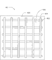
请参见图9,所述第一电极板42为一透明基板,其包括一第一表面420。所述第一电极板42包括多个第一行电极422和多个第一列电极424,该多个第一行电极422和多个第一列电极424交叉设置于该第一电极板42的第一表面420。该多个第一行电极422和多个第一列电极424之间相互绝缘。所述多个第一行电极422之间间隔设置,所属多个第一列电极424之间间隔设置。相邻的两个第一行电极422和相邻的两个第一列电极424之间形成一第一网格426。请参见图10,所述第二电极板44包括一第二表面440。所述第二电极板44的结构与第一电极板42的结构相同,其包括设置在第二电极板44的第二表面440的多个第二行电极442、多个第二列电极444和多个第二网格446。Please refer to FIG. 9 , the
所述第一电极板42的第一表面420和第二电极板44的第二表面440面对设置,所述第一表面420上的多个第一行电极422、多个第一列电极424和多个第一网格426与第二表面440上的多个第二行电极442、多个第二列电极444和多个第二网格446分别一一对应。每两个对应设置的第一网格426和第二网格446构成一显示单元。每个热致显示元件100设置于一个显示单元中,位于第一电极板42和第二电极板44之间。该多个热致显示元件100排列形成多个行和列。每个热致显示元件100对应该热致显示装置40的一个像素点。请一并参见图2,每个热致显示元件100的上基板1022位于第一电极板42的第一网格426中,并与该第一电极板42的第一表面420相互接触。该热致显示元件100的下基板1024位于与该第一网格426对应设置的第二网格446内,并与第二电极板44相互接触。所述上基板1022上的两个第一电极114分别与组成该第一网格426的一个第一行电极422和一个第一列电极424电连接。该两个第一电极114可分别通过电极引线与该第一行电极422和第一列电极424电连接。即,每一行的热致显示元件100的一个第一电极114与一个第一行电极422电连接,每一列的热致显示元件100的一个第一电极114与一个第一列电极424电连接。每个所述下基板1024上的两个第二电极116分别与组成该第二网格446的一个第二行电极442和一个第二列电极444电连接,即,每一行的热致显示元件100的一个第二电极116与一个第二行电极442电连接,每一列的热致显示元件100的一个第二电极116与一个第二列电极444电连接。The
进一步地,所述第一电极板42和第二电极板44之间可进一步包括至少一支撑结构(图未示)。该至少一支撑结构用于支撑第一电极板42和第二电极板44,使第一电极板42和第二电极板44间隔设置,从而使热致显示元件100位于第一电极板42和第二电极板44之间。该至少一支撑结构可防止第一电极板42或第二电极板44对热致显示元件产生压力,对热致显示元件100具有保护作用。具体地,该至少一支撑结构可以为设置在第一电极板42和第二电极板44之间的一边框,该至少一支撑结构与第一电极板42和第二电极板44封装形成一封闭结构,该多个热致显示元件100位于该封闭结构内。Further, at least one supporting structure (not shown) may be further included between the
该热致显示装置通过第一电极板和第二电极板上的行列电极,第一加热元件和第二加热元件,实现该热致显示装置的显示效果和擦拭效果。同时,通过控制不同的行列电极的导通,实现不同像素点的显示,从而显示不同的图样或字型。The thermotropic display device realizes the display effect and the wiping effect of the thermotropic display device through the row and column electrodes on the first electrode plate and the second electrode plate, the first heating element and the second heating element. At the same time, by controlling the conduction of different row and column electrodes, the display of different pixel points is realized, thereby displaying different patterns or fonts.
另外,本领域技术人员还可在本发明精神内做其他变化,当然,这些依据本发明精神所做的变化,都应包含在本发明所要求保护的范围之内。In addition, those skilled in the art can also make other changes within the spirit of the present invention. Of course, these changes made according to the spirit of the present invention should be included within the scope of protection claimed by the present invention.
Claims (19)
Priority Applications (3)
| Application Number | Priority Date | Filing Date | Title |
|---|---|---|---|
| CN200910239664.2A CN102116943B (en) | 2009-12-31 | 2009-12-31 | Thermotropic display element and thermotropic display device |
| US12/822,235 US8248682B2 (en) | 2009-12-31 | 2010-06-24 | Thermal-chromatic element and thermal-chromatic display device using the same |
| JP2010286049A JP5270653B2 (en) | 2009-12-31 | 2010-12-22 | Thermochromic element and thermochromic display device |
Applications Claiming Priority (1)
| Application Number | Priority Date | Filing Date | Title |
|---|---|---|---|
| CN200910239664.2A CN102116943B (en) | 2009-12-31 | 2009-12-31 | Thermotropic display element and thermotropic display device |
Publications (2)
| Publication Number | Publication Date |
|---|---|
| CN102116943A CN102116943A (en) | 2011-07-06 |
| CN102116943B true CN102116943B (en) | 2013-02-13 |
Family
ID=44187218
Family Applications (1)
| Application Number | Title | Priority Date | Filing Date |
|---|---|---|---|
| CN200910239664.2A Expired - Fee Related CN102116943B (en) | 2009-12-31 | 2009-12-31 | Thermotropic display element and thermotropic display device |
Country Status (3)
| Country | Link |
|---|---|
| US (1) | US8248682B2 (en) |
| JP (1) | JP5270653B2 (en) |
| CN (1) | CN102116943B (en) |
Families Citing this family (12)
| Publication number | Priority date | Publication date | Assignee | Title |
|---|---|---|---|---|
| CN101880035A (en) | 2010-06-29 | 2010-11-10 | 清华大学 | carbon nanotube structure |
| CN103728743B (en) | 2012-10-15 | 2017-02-01 | 北京富纳特创新科技有限公司 | Thermochromism display element and thermochromism display device |
| CN103728742B (en) * | 2012-10-15 | 2017-01-18 | 北京富纳特创新科技有限公司 | Thermochromism display element and thermochromism display device |
| CN103728741B (en) | 2012-10-15 | 2016-08-10 | 北京富纳特创新科技有限公司 | Thermochromatic element and thermochromatic display device |
| CN103728744B (en) | 2012-10-15 | 2016-12-21 | 北京富纳特创新科技有限公司 | Thermotropic display element and thermotropic display device |
| CN103885209B (en) * | 2012-12-22 | 2016-08-10 | 清华大学 | Thermochromatic element and thermochromatic display device |
| CN103010562B (en) * | 2013-01-10 | 2015-04-15 | 厦门新旺新材料科技有限公司 | Color-changed protection bag used under high-temperature environment |
| CN104865767B (en) * | 2015-06-05 | 2019-06-04 | 福建师范大学 | Electrochromic composite material, electrochromic device and preparation method thereof |
| CN106352298B (en) * | 2016-08-18 | 2019-06-11 | 长兴金诺机械有限公司 | A kind of changeable decorative lamp of pattern |
| CN106154679B (en) * | 2016-09-29 | 2019-12-31 | 京东方科技集团股份有限公司 | A display panel and its manufacturing method, electronic paper and its driving method |
| CN107479216B (en) * | 2017-08-28 | 2020-07-10 | 福建师范大学 | Thermochromic elements, thermochromic actuators and plant protection devices |
| CN119310758A (en) * | 2023-07-12 | 2025-01-14 | 清华大学 | Spatial light modulation unit and spatial light modulation device |
Citations (2)
| Publication number | Priority date | Publication date | Assignee | Title |
|---|---|---|---|---|
| US6287485B1 (en) * | 1997-12-15 | 2001-09-11 | Fuji Xerox Co., Ltd. | Volume-modulation coloration producing material, volume-modulation coloration producing composition, and optical element and method for optical modulation using the composition |
| CN101517473A (en) * | 2006-07-28 | 2009-08-26 | 法国圣戈班玻璃厂 | Active device having variable energy/optical properties |
Family Cites Families (5)
| Publication number | Priority date | Publication date | Assignee | Title |
|---|---|---|---|---|
| JP2004061818A (en) * | 2002-07-29 | 2004-02-26 | Toppan Forms Co Ltd | Electrophotographic toner, electrophotographic developer, image, sheet |
| JP2006065144A (en) * | 2004-08-30 | 2006-03-09 | Casio Comput Co Ltd | Display device and driving method of display device |
| JP4649179B2 (en) * | 2004-11-26 | 2011-03-09 | キヤノン株式会社 | Display device |
| CN101819335B (en) * | 2009-02-27 | 2014-01-15 | 清华大学 | Thermochromatic element and thermochromatic display device |
| CN102116942B (en) * | 2009-12-31 | 2013-02-13 | 清华大学 | Thermal display component and thermal display device |
-
2009
- 2009-12-31 CN CN200910239664.2A patent/CN102116943B/en not_active Expired - Fee Related
-
2010
- 2010-06-24 US US12/822,235 patent/US8248682B2/en active Active
- 2010-12-22 JP JP2010286049A patent/JP5270653B2/en not_active Expired - Fee Related
Patent Citations (2)
| Publication number | Priority date | Publication date | Assignee | Title |
|---|---|---|---|---|
| US6287485B1 (en) * | 1997-12-15 | 2001-09-11 | Fuji Xerox Co., Ltd. | Volume-modulation coloration producing material, volume-modulation coloration producing composition, and optical element and method for optical modulation using the composition |
| CN101517473A (en) * | 2006-07-28 | 2009-08-26 | 法国圣戈班玻璃厂 | Active device having variable energy/optical properties |
Non-Patent Citations (1)
| Title |
|---|
| JP特开2005-266624A 2005.09.29 |
Also Published As
| Publication number | Publication date |
|---|---|
| US20110157674A1 (en) | 2011-06-30 |
| CN102116943A (en) | 2011-07-06 |
| JP5270653B2 (en) | 2013-08-21 |
| JP2011138125A (en) | 2011-07-14 |
| US8248682B2 (en) | 2012-08-21 |
Similar Documents
| Publication | Publication Date | Title |
|---|---|---|
| CN102116943B (en) | Thermotropic display element and thermotropic display device | |
| CN102116942B (en) | Thermal display component and thermal display device | |
| CN102103276B (en) | Thermochromatic element and thermochromatic display device | |
| CN102103274B (en) | Thermochromic element and thermochromic display device | |
| JP6994047B2 (en) | Porous backplane for electro-optic displays | |
| CN101923227B (en) | Thermotropic display element and thermotropic display device | |
| US8217869B2 (en) | Flexible display system | |
| CN103885209A (en) | Thermochromic element and thermochromic display device | |
| CN103728744B (en) | Thermotropic display element and thermotropic display device | |
| CN103728743B (en) | Thermochromism display element and thermochromism display device | |
| CN103728742B (en) | Thermochromism display element and thermochromism display device | |
| TWI426477B (en) | Thermal display element and thermal display device | |
| US8432602B2 (en) | Chromatic element and chromatic display device using the same | |
| TWI443617B (en) | Thermochromatic device and thermochromatic display apparatus | |
| TWI451373B (en) | Thermal display element and thermal display device | |
| JP2016075877A (en) | Electrophoretic display medium sheet and electrophoretic display medium using the same | |
| JP4832074B2 (en) | Electrophoretic display medium | |
| JP5450932B2 (en) | Electrophoretic display device |
Legal Events
| Date | Code | Title | Description |
|---|---|---|---|
| C06 | Publication | ||
| PB01 | Publication | ||
| C10 | Entry into substantive examination | ||
| SE01 | Entry into force of request for substantive examination | ||
| C14 | Grant of patent or utility model | ||
| GR01 | Patent grant | ||
| CF01 | Termination of patent right due to non-payment of annual fee |
Granted publication date: 20130213 |
|
| CF01 | Termination of patent right due to non-payment of annual fee |