Description of drawings
Included and the accompanying drawing that constitute its ingredient of instructions shows several aspect of the present invention, and it plays a part to describe principle of the present invention with embodiment.Description of drawings is as follows:
Fig. 1 has a plurality of back skeleton views that are installed in the telecommunication assembly of the fiber optic splitter module in the frame, wherein, has decomposited the described adapter assembly one from described telecommunication assembly;
Fig. 2 is the top view of the telecommunication assembly of Fig. 1;
Fig. 3 is the front elevation of the telecommunication assembly of Fig. 1;
Fig. 4 is the rear view of the telecommunication assembly of Fig. 1;
Fig. 5 is the left side view of the telecommunication assembly of Fig. 1;
Fig. 6 is the right side view of the telecommunication assembly of Fig. 1;
Fig. 7 is the close up view of the telecommunication assembly of Fig. 1, and it shows and decompose the adapter assembly of coming out from telecommunication assembly;
Fig. 8 is the front perspective view of one of adapter assembly of Fig. 1;
Fig. 9 is the back perspective view of the adapter assembly of Fig. 8;
Figure 10 is the right side view of the adapter assembly of Fig. 8;
Figure 11 is the left side view of the adapter assembly of Fig. 8;
Figure 12 is the front elevation of the adapter assembly of Fig. 8;
Figure 13 is the rear view of the adapter assembly of Fig. 8;
Figure 14 is the top view of the adapter assembly of Fig. 8;
Figure 15 is the bottom view of the adapter assembly of Fig. 8;
Figure 16 is one a right side view in the fiber optic splitter module of Fig. 1, and it is illustrated as having the adapter assembly that is mounted thereon;
Figure 17 is the fiber optic splitter module of Figure 16 and the left side view of adapter assembly;
Figure 18 is the fiber optic splitter module of Figure 16 and the front elevation of adapter assembly;
Figure 19 is the fiber optic splitter module of Figure 16 and the rear view of adapter assembly;
Figure 20 is the front perspective view of the fiber optic splitter module of Figure 16, wherein, with the form of isolating it is shown and does not have the adapter assembly that is mounted thereon;
Figure 21 is the back perspective view of the fiber optic splitter module of Figure 20;
Figure 22 is the exploded view of the fiber optic splitter module of Figure 16, and it is illustrated as having the adapter assembly that decomposes from described fiber optic splitter module;
Figure 23 is the left view of the fiber optic splitter module of Figure 20;
Figure 24 is the right view of the fiber optic splitter module of Figure 20;
Figure 25 is the front elevation of the fiber optic splitter module of Figure 20;
Figure 26 is the rear view of the fiber optic splitter module of Figure 20;
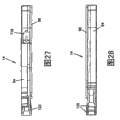
Figure 27 is the top view of the fiber optic splitter module of Figure 20;
Figure 28 is the backplan of the fiber optic splitter module of Figure 20;
Figure 29 is the right view of the fiber optic splitter module of Figure 20, and it is illustrated as not having lid, thereby has exposed the internal feature of fiber optic splitter module, and it comprises the route of the optical cable in the fiber optic splitter module;
Figure 30 is the sectional view that the profile line 30-30 along Figure 29 obtains;
Figure 31 shows the interior fiber optic splitter module of frame that the part is inserted into Fig. 1, described frame comprises the adapter assembly that is mounted thereon, wherein, show described fiber optic splitter module on the position before the connector of described splitter module contacts the shield that is positioned at described frame;
Figure 32 shows the fiber optic splitter module of Figure 31; It is illustrated as, and on the position in frame, the connector of fiber optic splitter module is tentatively contacted with the shield that is positioned at frame;
Figure 33 shows the fiber optic splitter module of Figure 31; It is illustrated as being on the position that has been inserted into fully in the described frame;
Figure 34 runs through the side cross-sectional, view that is in the fiber optic splitter module shown in Figure 32 in the described frame that the center of described fiber optic splitter module obtains;
Figure 35 runs through the side cross-sectional, view that is in the fiber optic splitter module shown in Figure 33 in the described frame that the center of described fiber optic splitter module obtains;
Figure 36 shows the front perspective view of the frame shown in Figure 1 that has the fiber optic splitter module that is mounted thereon, and it is in conjunction with shown in the dust cover/testing tool that decomposes from described frame, wherein, with described dust cover/testing tool as testing tool;
Figure 37 shows the front perspective view of the frame of Figure 36, and it is in conjunction with shown in the dust cover/testing tool that decomposes from described frame, wherein, with described dust cover/testing tool as dust cover;
Figure 38 shows dust cover/testing tool of Figure 36, and it is to combine shown in the exploded view of adapter assembly of Fig. 8;
Figure 39 is the front perspective view of dust cover/testing tool of Figure 36, and it is illustrated as having the adapter assembly that is mounted thereon, and is illustrated as having one of test connector of the dust cover/testing tool that decomposites from dust cover/testing tool;
Figure 40 is the back perspective view of dust cover/testing tool of Figure 36, and it is illustrated as not having the test connector of dust cover/testing tool;
Figure 41 is the front perspective view of dust cover/testing tool of Figure 40;
Figure 42 is the right view of dust cover/testing tool of Figure 40;
Figure 43 is the left view of dust cover/testing tool of Figure 40;
Figure 44 is the rear view of dust cover/testing tool of Figure 40;
Figure 45 is the top view of dust cover/testing tool of Figure 40;
Figure 46 is the bottom front perspective view according to clamping extension of the present invention;
Figure 47 is the bottom rear skeleton view of the clamping extension of Figure 46;
Figure 48 is the backplan of the clamping extension of Figure 46;
Figure 49 is the top view of the clamping extension of Figure 46;
Figure 50 is the right view of the clamping extension of Figure 46;
Figure 51 is the left view of the clamping extension of Figure 46; And
Figure 52 is the rear view of the clamping extension of Figure 46.
Embodiment
Now will be in detail with reference to exemplary aspect of the present invention illustrated in the accompanying drawings.As possible, will in all accompanying drawings, use the same reference numerals to represent identical or similar part.
Fig. 1-7 shows telecommunication assembly 10, and it comprises telco rack 12 and a plurality of fiber optic splitter modules 14 that are suitable for being installed in the described frame 12.Fiber optic splitter module 14 is configured to slidably be inserted in the frame 12, and can be by optical coupled to the adapter assembly 16 that is installed in the frame 12.Be installed in adapter assemblies 16 in the frame 12 and formed link position between the connector of connector that is connected to the input optical cable and splitter module 14, will provide more detailed discussion to it hereinafter.
Still with reference to figure 1-7, frame 12 is included in roof 18 and the diapire 20 that extends between a pair of relative lateral sidewalls 22 and 24.Frame 12 comprises the opening 30 by the opening 26 at the back side 28 of frame 12 and the front 32 by frame 12.Fiber optic splitter module 14 is inserted in the frame 12 by front openings 30.Adapter assembly 16 is inserted and contiguous described opening installation by the backside openings 26 of frame 12. Sidewall 22 and 24 includes from the otch 34 of described front openings 30 28 extensions towards the back side.Can see the splitter module 14 that is installed in the described frame 12 by described otch 34.The sidewall 22 and 24 of described frame 12 also defines the insertion portion 36 at the back side 28 that is in described frame 12, and it helps to touch adapter assembly 16.
In Fig. 1, frame 12 is shown to have eight fiber optic splitter modules 14 that are mounted thereon.Should be pointed out that in other embodiments, the size of frame can be made as and hold more or less splitter module.
Still with reference to figure 1-7, frame 12 comprises a plurality of installation sites 38 that are used for the mode received branch unit module 14 of sliding.Each installation site 38 defines slot 40 adjacent with the roof 18 of frame 12 and the slot 42 adjacent with the diapire 20 of frame 12.In Fig. 1, can see the slot 42 adjacent with diapire 20.The slot 40 adjacent with roof 18 has been shown in Figure 36 and 37.Slot 40 and 42 fronts 32 from frame 12 extend to the back side 28 of frame 12.Slot 40 and 42 is configured to receive the mounting flange 44 and 46 of the splitter module 14 shown in Figure 36 and 37, thereby make in module 14 and the frame 12 miscellaneous part (for example, the adapter of adapter assembly) aim at, so with connectorization in advance and/or preassembled transmission cable cooperate.
The slot 40 that limits below the roof 18 of frame 12 is darker than the slot 42 that limits on the diapire 20 in frame 12.The degree of depth of slot 40 and 42 is configured to be contained in the flange 44 and 46 of the different size that limits on the roof of splitter module 14 and the diapire.In this way, slot 40 and 42 and the mounting flange 44 and 46 of fiber optic splitter module 14 provide and guaranteed module 14 according to the correct locking mechanism in being inserted into frame 12.
Slot 40 below the roof 18 of frame 12 is defined in (with reference to Figure 36 and 37) between a plurality of dividing plates (bulkhead) 48.Dividing plate 48 extends to the back side 28 of frame 12 from the front 32 of frame 12.Front end 32 places in frame 12, each dividing plate 48 defines the preceding labial lamina 50 (Figure 35) of downward extension, but the deformation latching member 52 that has screen resilience (for example cantilever) of itself and splitter module 14 interlocking, thereby make splitter module 14 in place at frame 12 internal fixation, this point will be discussed in more detail hereinafter.
With reference to figure 1 and Fig. 7, at 28 places, rear end of frame 12, each dividing plate 48 defines the back side 54, and it has the fastener hole 56 of the securing member 58 (for example, thumbscrew) that is used to receive adapter assembly 16, thereby adapter assembly 16 is installed on the frame 12.In illustrated embodiment, fastener hole 56 is threaded, to receive the screw-type securing member.Should be pointed out that in other embodiments, can adopt the fastening structure of other types adapter assembly 16 to be installed to the back side 28 of frame 12.
With rear end 28 position adjacent, each dividing plate 48 also comprises horizontal slot 60 and vertical slot 62, they and the shape complementarity of adapter assembly 16, thereby slide reception adapter assembly 16.
Fig. 8-15 shows according to adapter assembly 16 of the present invention.Adapter assembly 16 is at the connector that is connected to the input optical cable and be installed between the connector of the splitter module 14 in the frame 12 and formed link position.
With reference to figure 8-15, adapter assembly 16 comprises two integrated adapters 64 of a part that is formed monoblock type shell 66.In other embodiments, also may adopt the adapter of other quantity.Each adapter 64 of adapter assembly 16 comprises front end 68 and rear end 70.The front end 68 of each adapter 64 receives the connector of fiber optic splitter module 14, and rear end 70 receiving ends are connected to the connector of input optical cable.
Adapter assembly shell 66 comprises the frame installation slide block 72 that extends from the top 74 of shell 66, and it is contained in the frame 12 by rear end 28.Slide block 72 defines horizontal component 76 and vertical part 78.Horizontal component 76 is configured to slidably be contained in the horizontal slot 60 of dividing plate 48, vertical part 78 is configured to slidably be contained in the vertical slot 62 of dividing plate 48.
Frame is installed slide block 72 and is comprised pair of flanges 80, and it is used to support securing member 58, thereby adapter assembly 16 is fixed to frame 12.As previously mentioned, the opening 56 that securing member 58 is placed the back side 54 by the following dividing plate 48 of the roof 18 that is positioned at frame 12 limit.Securing member 58 is preferably captive fastener.In the embodiment of as shown in the figure adapter assembly, securing member 58 is a thumbscrew, in other embodiments, can adopt the securing member of other types.
Thereby securing member 58 is rotated by screw thread adapter assembly 16 is connected to dividing plate 48.Also securing member 58 is configured to, in case adapter assembly 16 is installed on the frame 12, it can float for adapter assembly 16 provides with respect to the level of the scheduled volume of frame 12.Shown in Fig. 8-14, the securing member 58 of adapter assembly 16 comprises flange 81.Securing member 58 can move horizontally in flange 80 with respect to adapter assembly shell 66.As shown in figure 35, in case be installed on the frame 12, adapter assembly shell 66 can float with respect to securing member 58 levels between the back side of flange 81 and dividing plate 48 or move.For example, in Figure 35, adapter assembly 16 is illustrated as the distance A that can move or float towards the rear end of frame 12.In this way, when in unloading process, splitter module 14 being pulled out in the mode of sliding from frame 12, along with the adapter 64 of the connector 118 tension adapter assemblies 16 of the engagement of shunt 14, adapter assembly 16 can be towards splitter module 14 distance A of floating.In this way, for providing a certain amount of level that produces when being engaged to splitter module 14 or pulling down from it, adapter assembly 16 floats.
Shown in the exploded view of the adapter assembly among Figure 38 16, be presented in the adapter depression 84 that is formed in the adapter assembly shell 66 by the element of lateral opening 82 with each adapter 64.The element of each adapter 64 comprises cranse alignment sleeve 86 and a pair of inside half housing 88.By with by name " the ONE-PIECE SC ADAPTER " that issued on May 20th, 1993 for the common U.S. Patent No. 5317663 disclosed similar modes of the applicant are presented to these elements in the depression 84, at this its disclosure is introduced for your guidance.Panel 90 is closed opening 82, and protects the element in each adapter 64.Shown adapter 64 is the connectors that are used for the SC pattern, but also can adopt the adapter of other types, pattern and form and the connector that cooperates with these alternate adapter in the scope of the present disclosure.
In Figure 16-19, adapter assembly 16 is shown is being installed on the fiber optic splitter module 14 outside the frame 12.
Figure 20-30 shows according to one in the fiber optic splitter module 14 of the present invention.With reference to figure 20-30, fiber optic splitter module 14 comprises splitter module shell 92.Splitter module shell 92 comprises main housing portion 94 and removable cover 96.Main housing portion 94 is included in first lateral sidewalls 98 of extending between roof 100, diapire 102, rear wall 104 and the antetheca 106.Removable cover 96 defines second transverse wall 108 of splitter module shell 92, and has closed the open side of module main casing 94.
Be installed on the main housing portion 94 by the securing member (not shown) being passed be defined in securing member base 110 on the main housing portion 94 will cover 96.Lid 96 extends to outside first transverse wall 98, to form the top mounting flange 44 and the bottom mounting flange 46 of splitter module 14.With reference to Figure 23,25 and 26, as mentioned above, the base flange 46 of splitter module shell 92 and the corresponding slot 42 on the frame 12 are dimensionally less than the corresponding slot 40 on top flange 44 and the frame 12.The size of bottom slot 42 is set to, and base flange 46 can be contained in the slot 42, and bigger top flange 44 does not then match.It has been guaranteed module 14 is orientated according to specific expection and has placed in the front openings 30.In the total U.S. Patent No. of issuing on November 8th, 1,994 5363465 that is called " FIBER OPTIC CONNECTOR MODULE ", similar flange has been described, at this its disclosure is introduced for your guidance, in this way, optic module 14 is oriented in the adapter assembly 16 that install at the back side 28 that each installation site 38 is connected to contiguous frame 12 according to correct.
The rear wall 104 of main housing portion 94 comprises curvature portion 112, and it is configured to provide the bending radius protection for the optical cable within the inside 114.The rear wall 104 of main casing 92 also comprises insertion portion 116.The a pair of joints of optical fibre 118 that place insertion portion 116 places are outstanding backward from rear wall 104, thereby cooperate with the fiber adapter 64 of adapter assembly 16 in being installed in frame 12.
As shown in Figure 5 and Figure 6, make the antetheca 106 of module main casing 94 angled with respect to the front openings 30 of frame 12, it helps optical cable to be in favourable direction, leaves module 14 thereby make towards the position of expection.In other embodiments, in the scope of the present disclosure, can make antetheca 106 be roughly parallel to the front 32 of frame 12.
Each module 14 comprises two optical cable outlets 120 of extending from the antetheca 106 of module main casing 94.As shown in figure 22, optical cable outlet 120 slidably is installed on the main casing 94 of module 14, and will cover 96 when being installed on the main casing 94, make the lid 96 of module 14 capture optical cable and export 120.Optical cable outlet 120 defines outstanding back labial lamina 122, and it can slide to be inserted into around preceding fenestra 126 being used to of limiting and hold in the slot 124 of optical cable outlet 120.Lid 96 also comprises slit 128, and it receives the back labial lamina 122 of optical cable outlet 120, to capture optical cable outlet 120.Optical cable outlet 120 allows the telecommunication cable in the module 14 is drawn out to outside the module 14.As shown in figure 25, preferably the size of optical cable outlet 120 is set to enough approach, and in the profile that matches fiber optic splitter module 14, and keeps the density of telecommunication assembly 10 thus.
Main casing 94 comprises integrally formed flexible latch part 52 (that is, cantilever), and it is suitable for meshing the part of frame 12, thereby module 14 is fixed in the front openings 30 of frame 12.Flexible latch part 52 can also deflect, thereby allows module 14 is disassembled from frame 12.
Still with reference to figure 20-30, the latching member 52 of module 14 comprises finger-like pinched protrusion 130, preceding latch projection 132 and back latch projection 134.Preceding latch projection 132 and back latch projection 134 define depression 136 betwixt.Back latch projection 134 comprises dip plane 138, and when being inserted into module 14 in the frame 12, described dip plane 138 makes latching member 52 that elastic deflection take place downwards.Back latch projection 134 also comprises square 140, and it is relative with square 142 of preceding latch projection 132.
Capture the preceding labial lamina 50 of the dividing plate 48 on the installation site 38 that is in frame 12 in the depression 136 between two latch projection 132 and 134, thereby make module 14 in place at frame 12 internal fixation.During insertion,, and be captured in the depression 136 between two latch projection 132 and 134 latching member 52 resilience that will make progress along with the preceding labial lamina 50 of dividing plate 48 is crossed the rearward projection 134 of inclination.It is unsteady that depression 136 between two projections 132 of latching member 52 and 134 allows splitter modules 14 that a certain amount of level takes place frame 12 in, will do further discussion to it hereinafter.
By pressing latching member 52 downwards, make square 140 of rearward projection 134 to break away from labial lamina 50, and make module 14 skid off the dismounting that frame 12 is come execution module 14.Module 14 comprises fixing pinched protrusion 144, and it is relative and adjacent with it with flexible latch part 52, thereby helps module 14 is pulled down from frame 12.Fixing pinched protrusion 144 is formed the part of the antetheca 106 of module 14.Preferably fixing pinched protrusion 144 is placed on the module 14 position relative, thereby makes the user apply relative power latching member 52 and fixing pinched protrusion 144 with latching member 52, thus clamp module 14 securely, and with it from frame 12 dismountings.Preferably fixing pinched protrusion 144 is placed the position of the enough approach lock spares 52 on the module 14, thereby make the user apply power with two adjacent fingers.
Figure 22 shows the exploded view of fiber optic splitter module 14 of the internal part of specification module 14.In Figure 22, fiber optic splitter module 14 is shown to have and decomposes the adapter assembly 16 of coming out from module 14.
Within the inside 114 of main casing 94, splitter module 14 comprises first radius limiter 146 adjacent with the curvature portion 122 of the rear wall 104 of main casing 94.Splitter module 14 comprise with near the second adjacent radius limiter 148 of the antetheca 106 of the shell 94 of optical cable outlet 120.The connector 118 of splitter module 14 slidably is inserted in the relative slot 154 in the fenestra 156 that is formed on the rear wall 104.Connector 118 is outstanding from rear wall 104 at insertion portion 116 places of rear wall 104.The shell 150 of connector 118 comprises the lateral flange 152 that is contained in the relative slot 154, and described relative slot 154 is formed at and is used to hold in the fenestra 156 of connector 118.In case connector 118 is slidably inserted, lid 96 will capture connector 118 in the shell 92.
Diapire 102 such as the main casing 94 in the optics 158 and inner 114 of optical fiber splitter or fan out is adjacent.Make the internal fixation of optics 158 by clamping plate 160 (being carriage) near diapire 102.By the securing member (not shown) clamping plate 160 are installed on the clamping plate base 162 that is defined on the splitter module main casing 94.In the embodiment of as shown in the figure shell 94, clamping plate base 162 comprises two pairs of mounting holes 164 and 166.According to top one group of hole 164 or the one group of following hole 166 of size employing that is used for optics 158 is fixed to the clamping plate on the diapire 102.Should be noted that different opticses can have different thickness, and may need to adopt the clamping plate of different size that optic stationary is in place.In certain embodiments, can adopt two opticses that are stacked on another, in this case, can adopt less clamping plate that described two optic stationary are in place.
By one group of fiber optic cable management structure 168 optics 158 is offset from inside one side of first transverse wall 98.In the embodiment of illustrated module 14, described one group of fiber optic cable management structure 168 is the slim-lined constructions 170 that define fiber optic cable management slit 172 betwixt.With optics 158 fix in position the time, can make optical cable pass through slit 172 routes (please refer to Figure 29 and 30) between the inboard of the optics 158 and first transverse wall 98.
Splitter module main casing 94 also comprises and is positioned under second radius limiter 148 crimping (crimp) support 174 (for example, slot) that as a whole form adjacent with the antetheca 106 of shell 94.Shown in Figure 22 and 29, the press-fit component 176 that is crimped to the end of the optical cable that splits by optics 158 slidably is received in the crimping support 174.Press-fit component 176 defines square-shaped flange 175, defines sunk part 177 between square-shaped flange 175.Crimping support 174 comprises the structure with the press-fit component complementation, thereby after slidably being inserted into press-fit component 176 in the crimping support 174, avoids press-fit component 176 to be along the longitudinal movement under the effect of flange 175.In case with press-fit component 176 slide insert after, just by being installed to lid 96 on the splitter module main casing 94 with press-fit component 176 fix in position.In illustrated embodiment, nine crimping fixed slot 174 are arranged, each slot can four press-fit components 176 of outfit as many as.Other quantity also are possible.Also may adopt the complementary profile between other press-fit components and the crimping fixed slot that the coupling of sliding is provided, and after press-fit component being inserted in the crimping support, avoid press-fit component to move axially.
Figure 29 shows not with cover 96 fiber optic splitter module 14, and it has exposed the internal feature of the fiber optic splitter module 14 that comprises the route of optical cable in fiber optic splitter module 14.Figure 30 is the sectional view that the profile line 30-30 along Figure 29 obtains.
As shown in figure 29, first optical cable 178 extends from the optics 158 of connector 118 in being installed in module housing 92.As discussed earlier, optics 158 can be the optics of shunt, fan out or other types.In illustrated embodiment, optics 158 is the optical fiber splitters that are used for the signal of sub-thread is split into a plurality of secondary signals.In another embodiment, first optical cable 178 can be the multiply optical cable that has multiply optical fiber, and described optics can be each the fan out that is used for each strand is separated into a plurality of second optical cables.
Along with first optical cable 178 extends towards optics 158, described first optical cable 178 is inserted by the slit 172 (with reference to Figure 22,29 and 30) between the inboard of first transverse wall 98 of optics 158 and module housing 94, and make it around first radius limiter 146, afterwards before being received by optics 158 around second radius limiter 148.Second optical cable 180 begins to extend from optics 158, and before leading to crimping support 174 also always around first radius limiter 146.Other terminal optical cable (not shown) that are crimped to press-fit component 176 leave described module from crimping support 174 by module outlet 120.
The external cable (not shown) can extend to the rear end 70 of the adapter 64 of adapter assembly 16, and be terminated at connector (not shown among Figure 29), after being inserted into module 14 in the frame 12, described connector is connected to the connector 118 of module 14 by adapter 64 optics.Should be pointed out that the route of optical fiber cable in module 14 shown in Figure 29 and 30 is an example, also may adopt optical cable other routing modes in described module.
Be configured to make it can hold the bending radius optical fiber of reduction the embodiment of as shown in the figure fiber optic splitter module 14.The bending radius optical fiber that reduces can have the bending radius of about 15mm, and the bending radius optical fiber that does not reduce can have the bending radius of about 30mm.
The U.S. Patent application No.10980978 that has the applicant (on November 3rd, 2004 submitted to, " FIBER OPTIC MODULE AND SYSTEM INCLUDING REARCONNECTORS " by name); 11/138063 (on May 25th, 2005 submitted to, " FIBER OPTICSPLITTER MODULE " by name); 11/138889 (on May 25th, 2005 submitted to, " FIBEROPTIC ADAPTER MODULE " by name); And in 11/215837 (on August 29th, 2005 submitted to, " FIBER OPTIC SPLITTER MODULE WITH CONNECTOR ACCESS " by name) similar fiber optic splitter module has been described, at this its disclosure is introduced for your guidance.
The insertion of splitter module 14 in frame 12 has been shown in Figure 31-35.With reference to figure 31-35, the insertion of optic module 14 in the front openings 30 of frame 12 starts from module 14 to frame 12 and to the cooperation of the adapter 64 of adapter assembly 16.Along with the insertion of module 14, the top slot 40 of top flange 44 engagement frames 12, the bottom slot 42 of base flange 46 engagement frames 12.
Still with reference to figure 31-35, frame 12 comprises the flexible cover 182 that is on each installation site 38.Shield 182 is suitable for avoiding accidental exposure under light.Shield 182 is placed the front end 68 of each adapter 64 of adapter assembly 16.Before being placed on splitter module 14 on the relevant installation site 38, illumination and transmitting optical signal have been subjected to if be connected to the optical cable that has connector of the adapter 64 of adapter assembly 16, shield 182 will avoid accidental exposure to these signals so, because these signals may damage eyes or other responsive organs or near the communication facilities of infringement.Shown in Figure 31-33, shield 182 is pushed in the insertion of splitter module 14 open.
Along with module 14 is inserted by front openings 30, shield 182 deflects under the effect of module 14, thereby the connector 118 of module 14 can be cooperated with the adapter 64 of adapter assembly 16.Shield 182 preferably is made of the materials of elastically deformable, with module 14 from the installation site 38 when withdrawing from, it will turn back to described position.
For example, in Figure 31, fiber optic splitter module 14 is shown part is inserted in the frame 12 before the shield 182 of the connector 118 contact frames 12 of splitter module 14.In Figure 32, fiber optic splitter module 14 is shown on the position that is in the frame 12, wherein, and the shield 182 of the connector 118 initial contact frames 12 of fiber optic splitter module 14, thus shield 182 is removed (side cross-sectional, view has been shown among Figure 34).In Figure 33, fiber optic splitter module 14 is shown on the position of inserting fully that is in the frame 12, at this moment shield 182 has been removed (side cross-sectional, view has been shown among Figure 35).
Shield 182 is configured to, thus when connector 118 contact shield 182 is removed it, shield 182 not with cranse 184 engagements of the connector 118 of splitter module 14.On the contrary, the connector shell 150 in the outside can be pushed shield 182 open.
Can shield 182 be connected to frame 12 by securing member, perhaps as an alternative, can be with shield 182 and frame 12 as integrally formed, perhaps by spot welding or other tightening technologies installation shield 182.
Along with shield 182 complete deflections, the further insertion of module 14 will make connector 118 contact with adapter 64, and connector 118 is contained in the front end 68 of adapter 64.Along with the insertion of module 14, latching member 52 is to intrinsic deflection, resilience afterwards, thus the preceding labial lamina 50 of dividing plate 48 is captured in the depression 136.Now, module 14 be in can by first optical cable 178 in the inside modules 114, optics 158 and second optical cables 180 handle and transmission from the position of the signal of optical cable.
With reference to Figure 35, as mentioned above, the depression 136 between two projections 132 of latching member 52 and 134 is floated for splitter module 14 provides a certain amount of level in frame 12.As shown in figure 35, before square 140 of the preceding labial lamina 50 contact rearward projections 134 of dividing plate 48, allows described preceding labial lamina 50 displacement D.Splitter module 14 is configured to, with splitter module 14 when pull out the front 32 of frame 12, the preceding labial lamina 50 of dividing plate 48 before contact square 140 of rearward projection 134 the distance D of process less than the level that provides for adapter assembly 16 as discussed above float (that is distance A).
In this way, splitter module 14 provides a kind of protection form, adapter assembly 16 accidental of its connector 118 that can avoid module from the back side 28 of frame 12.With the dimensional configurations of the depression 136 of module 14 be, adapter assembly 16 is being pulled out distance enough far away towards the front of frame 12, thereby its tangential movement is being stopped and level that the connector 118 that making module 14 interrupts splitter module 14 before adapter 64 accidental is floated.
Figure 36-45 shows and is configured to dust cover/testing tool 190 of being used in combination with the adapter assembly 16 of telecommunication assembly 10.Dust cover/testing tool 190 comprises the main body 192 that has front end 194 and rear end 196.Dust cover/testing tool 190 comprises a pair of connector of giving prominence to from front end 194 118.As shown in figure 39, pair of connectors 118 is slided in the connector holder 193 of the main body 192 that is inserted into dust cover/testing tool 190.With the same in the shell 94 of splitter module 14, connector holder 193 comprises the slot 195 of the flange of the shell that is used to hold connector 118.Dust cover/testing tool 190 also comprise a pair of from the rear end 196 outstanding dust plugs 198.Dust cover/testing tool 190 comprises roof 200 and diapire 202 and first transverse side 204 and second transverse side 206.Roof and diapire 200 and 202 comprise respectively sliding and be inserted into top and base flange 208 and 210 in the frame 12, and this and fiber optic splitter module 14 are similar.First transverse side 204 comprises and is used for the radius limiter 212 of optical cable that leading end is connected to the connector 118 of dust cover/testing tool 190.There is first clamp 214 that forms as a whole with main body 192 at front end 194 places.At 196 places, rear end of dust cover/testing tool 190, there is second clamp 216 of the end that is defined in the radius limiter 212 that forms as a whole with main body 192.
Shown in Figure 36 and 37, dust cover/testing tool 190 slidably is inserted in the frame 12, and can be used to it according to two kinds of different modes.In Figure 36, dust cover/testing tool 190 is shown is used as testing tool, be input to optical signalling in the adapter assembly 16 with test.Because adapter assembly 16 is positioned at the rear end 28 of frame, the front end 68 of the adapter 64 of adapter assembly 16 is positioned at the inside of the frame 12 at 28 places, rear end, thereby becomes and be difficult to touch described connection, to realize test or other purposes.Pair of connectors 118 on the front end 194 of dust cover/testing tool 190 is designed to be connected to the adapter 64 of adapter assembly 16 when slidably being inserted into dust cover/testing tool 190 in the frame 12.In this way, can adapter assembly 16 not pulled down from frame 12, and need not to enter the connection at test adapter assembly 16 places under the situation of frame 12.
As shown in figure 37, can make 180 ° of dust cover/testing tool 190 upsets, and,, avoid pollutant effects with the inside of adapter seal 64 used as dust cover.If splitter module 14 is not inserted in one of the installation site 38 of frame 12, dust cover/testing tool 190 can play the effect of occupying device, and can be inserted sliding in the frame 12.Dust plug 198 comprises sunk part 199, and it is used to hold the outstanding projection 89 of the arm 91 of half housing that is in adapter 64 inside.Sunk part 199 helps to make dust plug to remain within the adapter 64.
In Figure 38, show dust cover/testing tool 190 and combine with the adapter assembly 16 that decomposites.In Figure 39, dust cover/testing tool 190 is illustrated as having the adapter assembly 16 that is mounted thereon, and is illustrated as having one of test connector 118 that decomposes the dust cover/testing tool 190 that comes out from dust cover/testing tool 190.
Figure 46-52 shows the clamping extension 218 that the connector 118 at the back side 70 of the adapter 64 that is suitable for and is connected to adapter assembly 16 is used in combination.To clamp the length that extension 218 is designed to increase the shell 150 of connector 118, thereby help under intensive environment, to touch each connector 118 such as telecommunication assembly 10.Preferably make cable termination before connector 118, at first will clamp extension and be installed on the optical cable.In case make connector 118 be terminated at optical cable, just make clamping extension 218 slip over the protective cover (boot) 220 of connector, and be installed on the shell 150 of connector 118, as shown in Figure 7.
With reference to figure 46-52, clamp extension 218 and comprise prolate body 222, it has four cantilevers that four front portions 224 from prolate body 222 extend out.Two relative cantilevers 226 and 228 comprise the outstanding fin 230 that is used for clamping surface 232 engagements of the shell 150 of connector 118.Two other relative cantilever 234 and 236 comprises the slit 238 that is used to mesh the flange 240 that is defined on the connector shell 150.By four cantilevers 226,228,234 and 236, will clamp extension 218 and snap fit onto on the connector shell 150.The back portion 242 that clamps extension main body 222 comprise top side 244, open bottom side 246 and two edges from positive 224 to the back side 242 the tapered cross side 248 and 250 of direction.Top side and bottom side 244 and 246 comprise clamping structure 252, clamp extension 218 to help pulling, to remove connector 118.
Above-mentioned explanation, example and data provide the complete description to manufacturing of the present invention and use.Owing under the situation that does not deviate from the spirit and scope of the present invention, can implement a lot of embodiments of the invention, thereby the present invention is covered by in the scope of claim.