WO2025070763A1 - Air handling unit - Google Patents
Air handling unit Download PDFInfo
- Publication number
- WO2025070763A1 WO2025070763A1 PCT/JP2024/034758 JP2024034758W WO2025070763A1 WO 2025070763 A1 WO2025070763 A1 WO 2025070763A1 JP 2024034758 W JP2024034758 W JP 2024034758W WO 2025070763 A1 WO2025070763 A1 WO 2025070763A1
- Authority
- WO
- WIPO (PCT)
- Prior art keywords
- heat exchanger
- header
- handling unit
- air handling
- flat tubes
- Prior art date
- Legal status (The legal status is an assumption and is not a legal conclusion. Google has not performed a legal analysis and makes no representation as to the accuracy of the status listed.)
- Pending
Links
Images


Classifications
-
- F—MECHANICAL ENGINEERING; LIGHTING; HEATING; WEAPONS; BLASTING
- F24—HEATING; RANGES; VENTILATING
- F24F—AIR-CONDITIONING; AIR-HUMIDIFICATION; VENTILATION; USE OF AIR CURRENTS FOR SCREENING
- F24F1/00—Room units for air-conditioning, e.g. separate or self-contained units or units receiving primary air from a central station
- F24F1/0007—Indoor units, e.g. fan coil units
- F24F1/0059—Indoor units, e.g. fan coil units characterised by heat exchangers
-
- F—MECHANICAL ENGINEERING; LIGHTING; HEATING; WEAPONS; BLASTING
- F24—HEATING; RANGES; VENTILATING
- F24F—AIR-CONDITIONING; AIR-HUMIDIFICATION; VENTILATION; USE OF AIR CURRENTS FOR SCREENING
- F24F13/00—Details common to, or for air-conditioning, air-humidification, ventilation or use of air currents for screening
- F24F13/22—Means for preventing condensation or evacuating condensate
Definitions
- Patent Document 1 US Pat. No. 5,341,870
- side panels are attached to the heat exchanger to ensure efficient heat exchange and prevent the air flow passing through the heat exchanger from leaking out from anywhere other than the heat exchange section.
- the heat exchanger includes a first heat exchanger and a second heat exchanger, and the first heat exchanger is positioned to cover the second heat exchanger, there is a risk of air leaking from the gap between the first and second heat exchangers.
- the air handling unit of the first aspect includes a first heat exchanger, a second heat exchanger, and a blower.
- the first heat exchanger includes a plurality of first flat tubes, a first heat transfer fin, a first header, and a second header.
- the plurality of first flat tubes have a first section and a second section sandwiched between a first bend of less than 180 degrees.
- the plurality of first flat tubes are aligned along a first direction.
- the first heat transfer fin is provided between adjacent plurality of first flat tubes.
- the first header is attached to the ends of the plurality of first flat tubes on the first section side.
- the second header is attached to the ends of the plurality of first flat tubes on the second section side.
- the second heat exchanger includes a plurality of second flat tubes, a second heat transfer fin, a third header, and a fourth header.
- the plurality of second flat tubes have a third section and a fourth section sandwiched between a second bend of less than 180 degrees.
- the second flat tubes are arranged along the first direction.
- the second heat transfer fins are provided between adjacent second flat tubes.
- the third header is attached to the ends of the second flat tubes on the third section side.
- the fourth header is attached to the ends of the second flat tubes on the fourth section side.
- the blower generates an air flow passing through the first heat exchanger and the second heat exchanger.
- the first and second sections are arranged to cover the third and fourth sections, respectively.
- the air handling unit further includes a first member.
- the first member is attached to the end of the first heat exchanger in the first direction. The first member prevents the air flow generated by the blower from leaking from a gap between the first and second heat exchangers.
- the first member prevents the air flow generated by the blower from leaking through the gap between the first heat exchanger and the second heat exchanger.
- the air handling unit can perform efficient heat exchange.
- the air handling unit of the second aspect is the air handling unit of the first aspect, in which the width of the first part is smaller than the width of the first header in a direction perpendicular to the direction in which the first part extends when viewed from the first direction.
- the width of the third part is smaller than the width of the third header in a direction perpendicular to the direction in which the third part extends when viewed from the first direction.
- the air handling unit of the third aspect is the air handling unit of the first or second aspect, in which the first member is a flat plate.
- a first recess is formed in a first surface of the first member on the side of the first heat exchanger. An end of the first heat exchanger in the first direction is inserted into the first recess.
- the air handling unit of the third aspect can determine the position of the first heat exchanger and fix the first heat exchanger by inserting the end of the first heat exchanger in the first direction into the first recess. Furthermore, the air handling unit can more effectively prevent the air flow generated by the blower device from leaking through the gap between the first heat exchanger and the second heat exchanger.
- the air handling unit of the fourth aspect is the air handling unit of the third aspect, in which the first member is attached to the end of the second heat exchanger in the first direction. A second recess is formed in the first surface of the first member. The end of the second heat exchanger in the first direction is inserted into the second recess.
- the air handling unit of the fourth aspect can determine the position of the second heat exchanger and fix the second heat exchanger by inserting the end of the second heat exchanger in the first direction into the second recess. Furthermore, the air handling unit can more effectively prevent the air flow generated by the blower from leaking through the gap between the first heat exchanger and the second heat exchanger.
- the air handling unit of a fifth aspect is the air handling unit of the first or second aspect, in which the first member is a flat plate.
- a first convex portion is formed on a first surface of the first member facing the first heat exchanger.
- the first convex portion conforms to the shape of the end portion of the first heat exchanger in the first direction.
- the first convex portion has a second convex portion and a third convex portion.
- the second convex portion conforms to the shape of the second heat exchanger side at the end portion of the first heat exchanger in the first direction.
- the third convex portion conforms to the shape of the opposite side to the second heat exchanger at the end portion of the first heat exchanger in the first direction.
- the air handling unit of the fifth aspect can determine the position of the first heat exchanger and fix the first heat exchanger by inserting the end of the first direction of the first heat exchanger between the second convex portion and the third convex portion. Furthermore, the air handling unit can more effectively prevent the air flow generated by the blower device from leaking through the gap between the first heat exchanger and the second heat exchanger.
- the air handling unit of a sixth aspect is the air handling unit of the fifth aspect, in which the first member is attached to the end of the second heat exchanger in the first direction.
- a fourth convex portion is formed on the first surface of the first member.
- the fourth convex portion conforms to the shape of the end of the second heat exchanger in the first direction.
- the fourth convex portion has a fifth convex portion and a sixth convex portion.
- the fifth convex portion conforms to the shape of the side opposite the first heat exchanger at the end of the second heat exchanger in the first direction.
- the sixth convex portion conforms to the shape of the first heat exchanger side at the end of the second heat exchanger in the first direction.
- the air handling unit of the sixth aspect can determine the position of the second heat exchanger and fix the second heat exchanger by inserting the end of the second heat exchanger in the first direction between the fifth convex portion and the sixth convex portion. Furthermore, the air handling unit can more effectively prevent the air flow generated by the blower device from leaking through the gap between the first heat exchanger and the second heat exchanger.
- the air handling unit of the seventh aspect is the air handling unit of any one of the first aspect to the sixth aspect, further comprising a second member.
- the second member is disposed in the gap between the first folded portion and the second folded portion.
- a third recess is formed in the first surface of the first member facing the first heat exchanger. The end of the second member in the first direction is inserted into the third recess.
- the seventh aspect of the air handling unit is capable of determining the position of the second member and fixing the second member by inserting the end of the second member in the first direction into the third recess.
- the air handling unit can also prevent the air flow generated by the blower from leaking through the gap between the first bent portion and the second bent portion.
- the air handling unit of an eighth aspect is the air handling unit of any one of the first aspect to the sixth aspect, further comprising a second member.
- the second member is disposed in the gap between the first folded portion and the second folded portion.
- a seventh convex portion is formed on the first surface of the first member on the side of the first heat exchanger. The seventh convex portion follows the shape of the end portion of the second member in the first direction.
- the air handling unit of the eighth aspect can determine the position of the second member and fix the second member by inserting the end of the second member in the first direction into the space surrounded by the seventh convex portion.
- the air handling unit can also prevent the air flow generated by the blower from leaking through the gap between the first bent portion and the second bent portion.
- the air handling unit of a ninth aspect is the air handling unit of any one of the first aspect to the eighth aspect, further comprising a first drain pan.
- the first drain pan receives condensation water from the first heat exchanger and the second heat exchanger.
- the first drain pan is disposed on the first header, the second header, the third header, and the fourth header side.
- the first drain pan has an opening. The opening allows the air flow generated by the blower to pass through.
- the air handling unit of a tenth aspect is any of the air handling units of the ninth aspect, further comprising a second drain pan and a support member.
- the second drain pan receives condensation water from the first heat exchanger and the second heat exchanger.
- the support member connects the first member and the second drain pan.
- the first heat exchanger is fixed to the second drain pan by the first member and the support member.
- FIG. 2 is a cross-sectional view of the drain pan as viewed from a first direction.
- FIG. FIG. 2 is a side view of the air handling unit as viewed from a first direction.
- FIG. 2 is a side view of the air handling unit as viewed from a first direction.
- FIG. 2 is a side view of the air handling unit as viewed from a first direction.
- FIG. 4 is a top view of the heat exchanger seen from a second direction.
- FIG. 13 is a diagram showing a first surface of a side panel on the heat exchanger side in modification 1D. This is a cross-sectional view taken along the line CC in FIG. This is a cross-sectional view taken along the line D-D in FIG.
- the multiple first flat tubes 231 and the multiple second flat tubes 232 are arranged side by side along a predetermined direction.
- the first direction D1 is a horizontal direction.
- the multiple first flat tubes 231 and the multiple second flat tubes 232 located in the center in the first direction D1 are omitted.
- the direction in which air flows through the internal space of the casing 11 is referred to as the second direction D2.
- the second direction D2 is a vertical downward direction.
- the first heat transfer fin 261 is fixed to the first portion 231a and the second portion 231b between the first flat tubes 231 adjacent along the first direction D1. More specifically, the first heat transfer fin 261 is provided between the first portions 231a adjacent along the first direction D1. The first heat transfer fin 261 is fixed to the first portion 231a by fixing the peaks of the corrugations to the main surface of the first portion 231a. The first heat transfer fin 261 is also provided between the second portions 231b adjacent along the first direction D1. The first heat transfer fin 261 is fixed to the second portion 231b by fixing the peaks of the corrugations to the main surface of the second portion 231b.
- the second heat transfer fin 262 is fixed to the third portion 232a and the fourth portion 232b between the second flat tubes 232 adjacent along the first direction D1. More specifically, the second heat transfer fin 262 is provided between the third portions 232a adjacent along the first direction D1. The second heat transfer fin 262 is fixed to the third portion 232a by fixing the peak of the corrugation to the main surface of the third portion 232a. The second heat transfer fin 262 is also provided between the fourth portions 232b adjacent along the first direction D1. The second heat transfer fin 262 is fixed to the fourth portion 232b by fixing the peak of the corrugation to the main surface of the fourth portion 232b.
- the first header 21a, the second header 21b, the third header 21c, and the fourth header 21d are arranged to extend in the first direction D1.
- the first header 21a, the second header 21b, the third header 21c, and the fourth header 21d are arranged above the drain pan 24.
- the first header 21a, the second header 21b, the third header 21c, and the fourth header 21d are connected to an external refrigerant circuit via refrigerant piping 25.
- the shielding member 50 is a block-shaped member extending along the first direction D1.
- the shielding member 50 is made of, for example, resin.
- the shielding member 50 is disposed in the gap between the first bent portion 231c and the second bent portion 232c.
- the length of the shielding member 50 along the first direction D1 is equal to the lengths of the first heat exchanger 41 and the second heat exchanger 42 along the first direction D1.
- side panel 60 is a flat plate having a substantially triangular shape.
- Side panel 60 is made of, for example, resin.
- Air handling unit 100 has a pair of side panels 60. The pair of side panels 60 is attached to the ends of first heat exchanger 41 and second heat exchanger 42 in the first direction D1 so as to sandwich first heat exchanger 41 and second heat exchanger 42 along the first direction D1. Side panel 60 prevents the air flow generated by blower device 30 from leaking from a gap between first heat exchanger 41 and second heat exchanger 42.
- a first recess 91, a second recess 92, and a third recess 93 are formed on the first surface 61 of the side panel 60 on the side of the first heat exchanger 41 and the second heat exchanger 42.
- the end of the first heat exchanger 41 in the first direction D1 is inserted into the first recess 91.
- the end of the second heat exchanger 42 in the first direction D1 is inserted into the second recess 92.
- the end of the shielding member 50 in the first direction D1 is inserted into the third recess 93.
- the drain pan 24 is disposed on the side of the first header 21a, the second header 21b, the third header 21c, and the fourth header 21d. Specifically, the drain pan 24 is disposed below the first header 21a, the second header 21b, the third header 21c, and the fourth header 21d.
- the drain pan 24 receives condensed water from the first heat exchanger 41 and the second heat exchanger 42. Specifically, the drain pan 24 receives condensed water from the plurality of first flat tubes 231, the plurality of second flat tubes 232, the first header 21a, the second header 21b, the third header 21c, and the fourth header 21d.
- the condensed water is water that is generated on the surfaces of the first flat tubes 231, the second flat tubes 232, the first header 21a, the second header 21b, the third header 21c, and the fourth header 21d due to heat exchange between the refrigerant flowing inside the first flat tubes 231 and the second flat tubes 232 and the air passing through the heat exchange chamber 17.
- the generated condensed water flows down the surfaces of the first flat tubes 231, the second flat tubes 232, the first header 21a, the second header 21b, the third header 21c, and the fourth header 21d due to its own weight, and is received in the drain pan 24.
- the drain pan 24 is fixed to the support member 12.
- the drain pan 24 has a first wall 24a, a second wall 24b, a receiving portion 24c, and a drain outlet 24d. When viewed from the second direction D2, the drain pan 24 has a substantially rectangular shape.
- the first wall 24a surrounds an opening 24f through which air flowing in the second direction D2 through the heat exchange chamber 17 passes.
- the drain pan 24 has an opening 24f through which the air flow generated by the blower 30 passes.
- the opening 24f is located in the center of the drain pan 24 when the drain pan 24 is viewed from the second direction D2.
- the opening 24f has a substantially rectangular shape when viewed from the second direction D2.
- the air flowing through the heat exchange chamber 17 in the second direction D2 passes through the opening 24f and flows into the blower chamber 18.
- the second wall 24b is located outside the first wall 24a when the drain pan 24 is viewed from the second direction D2.
- the receiving portion 24c connects the lower end of the first wall 24a and the lower end of the second wall 24b.
- the receiving portion 24c corresponds to the bottom of the drain pan 24.
- the receiving portion 24c is disposed below the first header 21a, the second header 21b, the third header 21c, and the fourth header 21d.
- the space surrounded by the first wall 24a, the second wall 24b, and the receiving portion 24c is a space for receiving condensed water and temporarily storing it as drain water.
- the drain outlet 24d is formed in the second wall 24b.
- the drain outlet 24d is formed in a corner of the rectangular shape of the drain pan 24 when the drain pan 24 is viewed from the second direction D2.
- the drain outlet 24d is a hole for discharging drain water to the outside of the drain pan 24.
- the receiving portion 24c has a first surface 24e, which is an upper surface that slopes downward from the first wall 24a to the second wall 24b.
- first surface 24e is an upper surface that slopes downward from the first wall 24a to the second wall 24b.
- the receiving portion 24c has a portion where the height position of the first surface 24e decreases from the center side where the first wall 24a is located to the outside where the second wall 24b is located.
- the first surface 24e corresponds to the bottom surface of the drain pan 24.
- the first surface 24e is the surface that comes into contact with the drain water.
- the heat exchanger includes a first heat exchanger and a second heat exchanger, and the first heat exchanger is positioned to cover the second heat exchanger, there is a risk of air leaking from the gap between the first and second heat exchangers.
- the air handling unit 100 of this embodiment includes a first heat exchanger 41, a second heat exchanger 42, and a blower 30.
- the first heat exchanger 41 includes a plurality of first flat tubes 231, a first heat transfer fin 261, a first header 21a, and a second header 21b.
- the plurality of first flat tubes 231 include a first portion 231a and a second portion 231b sandwiched between a first bend portion 231c of less than 180 degrees.
- the plurality of first flat tubes 231 are aligned along the first direction D1.
- the first heat transfer fin 261 is provided between the plurality of adjacent first flat tubes 231.
- the first header 21a is attached to the end of the plurality of first flat tubes 231 on the first portion 231a side.
- the second header 21b is attached to the end of the plurality of first flat tubes 231 on the second portion 231b side.
- the second heat exchanger 42 has a plurality of second flat tubes 232, a second heat transfer fin 262, a third header 21c, and a fourth header 21d.
- the plurality of second flat tubes 232 have a third portion 232a and a fourth portion 232b sandwiching a second bent portion 232c of less than 180 degrees.
- the plurality of second flat tubes 232 are arranged along the first direction D1.
- the second heat transfer fin 262 is provided between the plurality of adjacent second flat tubes 232.
- the third header 21c is attached to the end of the plurality of second flat tubes 232 on the third portion 232a side.
- the fourth header 21d is attached to the end of the plurality of second flat tubes 232 on the fourth portion 232b side.
- the blower device 30 generates a flow of air passing through the first heat exchanger 41 and the second heat exchanger 42.
- the first portion 231a and the second portion 231b are arranged to cover the third portion 232a and the fourth portion 232b, respectively.
- the air handling unit 100 further includes a side panel 60.
- the side panel 60 is attached to an end of the first heat exchanger 41 in the first direction D1.
- the side panel 60 prevents the air flow generated by the blower device 30 from leaking through a gap between the first heat exchanger 41 and the second heat exchanger 42.
- the side panel 60 prevents the air flow generated by the blower 30 from leaking through the gap between the first heat exchanger 41 and the second heat exchanger 42. As a result, the air handling unit 100 can perform heat exchange efficiently.
- width W1 of first portion 231a is smaller than width W2 of first header 21a.
- width W3 of third portion 232a is smaller than width W4 of third header 21c.
- side panel 60 is a flat plate.
- a first recess 91 is formed in a first surface 61 of side panel 60 on the side of first heat exchanger 41.
- An end of first heat exchanger 41 in first direction D1 is inserted into first recess 91.
- the air handling unit 100 can determine the position of the first heat exchanger 41 and fix the first heat exchanger 41 by inserting the end of the first heat exchanger 41 in the first direction D1 into the first recess 91. Furthermore, the air handling unit 100 can more effectively prevent the air flow generated by the blower device 30 from leaking through the gap between the first heat exchanger 41 and the second heat exchanger 42.
- side panel 60 is attached to an end of second heat exchanger 42 in first direction D1.
- a second recess 92 is formed in first surface 61 of side panel 60. The end of second heat exchanger 42 in first direction D1 is inserted into second recess 92.
- the air handling unit 100 can determine the position of the second heat exchanger 42 and fix the second heat exchanger 42 by inserting the end of the second heat exchanger 42 in the first direction D1 into the second recess 92. Furthermore, the air handling unit 100 can more effectively prevent the air flow generated by the blower 30 from leaking through the gap between the first heat exchanger 41 and the second heat exchanger 42.
- Air handling unit 100 further includes a shielding member 50.
- Shielding member 50 is disposed in the gap between first folded portion 231c and second folded portion 232c.
- a third recess 93 is formed in first surface 61 of side panel 60 on the first heat exchanger 41 side. An end of shielding member 50 in first direction D1 is inserted into third recess 93.
- the air handling unit 100 can determine the position of the shielding member 50 and fix the shielding member 50 by inserting the end of the shielding member 50 in the first direction D1 into the third recess 93.
- the air handling unit 100 can also prevent the air flow generated by the blower 30 from leaking through the gap between the first bent portion 231c and the second bent portion 232c.
- Air handling unit 100 further includes a drain pan 24.
- Drain pan 24 receives condensation water from first heat exchanger 41 and second heat exchanger 42. Drain pan 24 is disposed on the side of first header 21a, second header 21b, third header 21c, and fourth header 21d. Drain pan 24 has an opening 24f. Opening 24f allows the flow of air generated by blower 30 to pass through.
- Air handling unit 100 may be installed with the positions of heat exchange chamber 17 and blower chamber 18 interchanged. Air handling unit 101 shown in Fig. 14 is air handling unit 100 with the positions of heat exchange chamber 17 and blower chamber 18 interchanged. Air generated by blower device 30 flows vertically upward through the internal space of casing 11 from suction port 13 toward air outlet 14.
- air handling unit 100 is installed vertically so that the longitudinal direction of casing 11 is along the vertical direction.
- air handling unit 100 may be installed horizontally so that the longitudinal direction of casing 11 is along the horizontal direction.
- Air handling unit 102 shown in Fig. 15 is air handling unit 100 rotated by 90° when viewed from first direction D1. Air generated by blower 30 flows horizontally through the internal space of casing 11 from intake port 13 to exhaust port 14.
- the air handling unit 102 further includes a second drain pan 27 and a support member 28.
- the second drain pan 27 is disposed below the heat exchanger 20.
- the second drain pan 27 receives condensation water that falls from the surfaces of the first heat exchanger 41 and the second heat exchanger 42 due to their own weight.
- the support member 28 connects the side panel 60 and the second drain pan 27.
- the first heat exchanger 41 and the second heat exchanger 42 are fixed to the second drain pan 27 by the side panel 60 and the support member 28.
- the air handling unit 102 can secure the first heat exchanger 41 and the second heat exchanger 42 to the second drain pan 27 using the side panel 60 and the support member 28.
- the air handling unit 102 may be installed with the positions of the heat exchange chamber 17 and the blower chamber 18 interchanged.
- the air handling unit 103 shown in FIG. 16 is an air handling unit 102 with the positions of the heat exchange chamber 17 and the blower chamber 18 interchanged.
- the air generated by the blower device 30 flows horizontally through the internal space of the casing 11 from the intake port 13 toward the exhaust port 14.
- the length of the first heat exchanger 41 along the first direction D1 is equal to the length of the second heat exchanger 42 along the first direction D1.
- the length of the first heat exchanger 41 along the first direction D1 may be longer than the length of the second heat exchanger 42 along the first direction D1.
- the end of the second heat exchanger 42 in the first direction D1 is located inside the first heat exchanger 41.
- one set of side panels 60 is attached to the end of the first heat exchanger 41 in the first direction D1 so as to sandwich the first heat exchanger 41 along the first direction D1
- another set of side panels 80 is attached to the end of the second heat exchanger 42 in the first direction D1 so as to sandwich the second heat exchanger 42 along the first direction D1.
- a first recess 91 is formed in the first surface 61 of the side panel 60 on the first heat exchanger 41 side.
- a second recess 92 is formed in the first surface 81 of the side panel 80 on the second heat exchanger 42 side.
- the length of the first heat exchanger 41 along the first direction D1 or the length of the second heat exchanger 42 along the first direction D1 may be adjusted by a spacer.
- the spacer is attached to the end of the first heat exchanger 41 or the second heat exchanger 42 in the first direction D1.
- the side panel 60 or the side panel 80 is attached to the spacer.
- a first recess 91, a second recess 92, and a third recess 93 are formed on the first surface 61 of the side panel 60 facing the first heat exchanger 41 and the second heat exchanger 42.
- a first convex portion 71, a fourth convex portion 74, and a seventh convex portion 77 may be formed on the first surface 61 of the side panel 60 facing the first heat exchanger 41 and the second heat exchanger 42, as shown in FIG.
- the first convex portion 71 conforms to the shape of the end of the first heat exchanger 41 in the first direction D1.
- the first convex portion 71 has a second convex portion 72 and a third convex portion 73.
- the second convex portion 72 conforms to the shape of the second heat exchanger 42 side at the end of the first heat exchanger 41 in the first direction D1.
- the third convex portion 73 conforms to the shape of the opposite side to the second heat exchanger 42 at the end of the first heat exchanger 41 in the first direction D1. As shown in FIG.
- the air handling unit 100 can determine the position of the first heat exchanger 41 and fix the first heat exchanger 41 by inserting the end of the first heat exchanger 41 in the first direction D1 between the second convex portion 72 and the third convex portion 73. Furthermore, the air handling unit 100 can more effectively prevent the air flow generated by the blower 30 from leaking through the gap between the first heat exchanger 41 and the second heat exchanger 42.
- the fourth convex portion 74 conforms to the shape of the end of the second heat exchanger 42 in the first direction D1.
- the fourth convex portion 74 has a fifth convex portion 75 and a sixth convex portion 76.
- the fifth convex portion 75 conforms to the shape of the end of the second heat exchanger 42 in the first direction D1 on the opposite side to the first heat exchanger 41.
- the sixth convex portion 76 conforms to the shape of the end of the second heat exchanger 42 in the first direction D1 on the first heat exchanger 41 side. As shown in FIG.
- the air handling unit 100 can determine the position of the second heat exchanger 42 and fix the second heat exchanger 42 by inserting the end of the second heat exchanger 42 in the first direction D1 between the fifth convex portion 75 and the sixth convex portion 76. Furthermore, the air handling unit 100 can more effectively prevent the air flow generated by the blower 30 from leaking through the gap between the first heat exchanger 41 and the second heat exchanger 42.
- the seventh convex portion 77 conforms to the shape of the end portion of the shielding member 50 in the first direction D1.
- the air handling unit 100 can determine the position of the shielding member 50 and fix the shielding member 50 by inserting the end portion of the shielding member 50 in the first direction D1 into the space surrounded by the seventh convex portion 77.
- the air handling unit 100 can prevent the air flow generated by the blower 30 from leaking through the gap between the first bent portion 231c and the second bent portion 232c.
- a seventh convex portion 77 may be formed instead of the third concave portion 93 on the first surface 61 of the side panel 60 on the side of the first heat exchanger 41 and the second heat exchanger 42, on which the first concave portion 91 and the second concave portion 92 are formed.
- a third concave portion 93 may be formed instead of the seventh convex portion 77 on the first surface 61 of the side panel 60 on the side of the first heat exchanger 41 and the second heat exchanger 42, on which the first convex portion 71 and the fourth convex portion 74 are formed.
Landscapes
- Engineering & Computer Science (AREA)
- Chemical & Material Sciences (AREA)
- Combustion & Propulsion (AREA)
- Mechanical Engineering (AREA)
- General Engineering & Computer Science (AREA)
- Physics & Mathematics (AREA)
- Thermal Sciences (AREA)
- Other Air-Conditioning Systems (AREA)
Abstract
Description
エアハンドリングユニットに関する。 Regarding air handling units.
特許文献1(米国特許第5341870号明細書)に示されているように、効率的に熱交換を行うため、熱交換器にサイドパネルを取り付け、熱交換器を通過する空気の流れが熱交換部以外の場所から漏れることを防止する技術がある。 As shown in Patent Document 1 (US Pat. No. 5,341,870), there is a technology in which side panels are attached to the heat exchanger to ensure efficient heat exchange and prevent the air flow passing through the heat exchanger from leaking out from anywhere other than the heat exchange section.
熱交換器が第1熱交換器および第2熱交換器を備え、第1熱交換器が第2熱交換器を覆うように配置される場合、第1熱交換器と第2熱交換器との隙間から空気の流れが漏れる恐れがある。 If the heat exchanger includes a first heat exchanger and a second heat exchanger, and the first heat exchanger is positioned to cover the second heat exchanger, there is a risk of air leaking from the gap between the first and second heat exchangers.
第1観点のエアハンドリングユニットは、第1熱交換器と、第2熱交換器と、送風装置と、を備える。第1熱交換器は、複数の第1扁平管と、第1伝熱フィンと、第1ヘッダーと、第2ヘッダーと、を有する。複数の第1扁平管は、180度未満の第1折り曲げ部を挟んで第1部および第2部を有する。複数の第1扁平管は、第1方向に沿って並ぶ。第1伝熱フィンは、隣り合う複数の第1扁平管の間に設けられる。第1ヘッダーは、複数の第1扁平管の第1部側の端部に取り付けられる。第2ヘッダーは、複数の第1扁平管の第2部側の端部に取り付けられる。第2熱交換器は、複数の第2扁平管と、第2伝熱フィンと、第3ヘッダーと、第4ヘッダーと、を有する。複数の第2扁平管は、180度未満の第2折り曲げ部を挟んで第3部および第4部を有する。複数の第2扁平管は、第1方向に沿って並ぶ。第2伝熱フィンは、隣り合う複数の第2扁平管の間に設けられる。第3ヘッダーは、複数の第2扁平管の第3部側の端部に取り付けられる。第4ヘッダーは、複数の第2扁平管の第4部側の端部に取り付けられる。送風装置は、第1熱交換器および第2熱交換器を通過する空気の流れを生成する。第1部および第2部はそれぞれ、第3部および第4部を覆うように配置される。エアハンドリングユニットは、第1部材をさらに備える。第1部材は、第1熱交換器の第1方向の端部に取り付けられる。第1部材は、送風装置が生成する空気の流れが、第1熱交換器と第2熱交換器との隙間から漏れることを防止する。 The air handling unit of the first aspect includes a first heat exchanger, a second heat exchanger, and a blower. The first heat exchanger includes a plurality of first flat tubes, a first heat transfer fin, a first header, and a second header. The plurality of first flat tubes have a first section and a second section sandwiched between a first bend of less than 180 degrees. The plurality of first flat tubes are aligned along a first direction. The first heat transfer fin is provided between adjacent plurality of first flat tubes. The first header is attached to the ends of the plurality of first flat tubes on the first section side. The second header is attached to the ends of the plurality of first flat tubes on the second section side. The second heat exchanger includes a plurality of second flat tubes, a second heat transfer fin, a third header, and a fourth header. The plurality of second flat tubes have a third section and a fourth section sandwiched between a second bend of less than 180 degrees. The second flat tubes are arranged along the first direction. The second heat transfer fins are provided between adjacent second flat tubes. The third header is attached to the ends of the second flat tubes on the third section side. The fourth header is attached to the ends of the second flat tubes on the fourth section side. The blower generates an air flow passing through the first heat exchanger and the second heat exchanger. The first and second sections are arranged to cover the third and fourth sections, respectively. The air handling unit further includes a first member. The first member is attached to the end of the first heat exchanger in the first direction. The first member prevents the air flow generated by the blower from leaking from a gap between the first and second heat exchangers.
第1観点のエアハンドリングユニットでは、第1部材は、送風装置が生成する空気の流れが、第1熱交換器と第2熱交換器との隙間から漏れることを防止する。その結果、エアハンドリングユニットは、効率的に熱交換を行うことができる。 In the air handling unit of the first aspect, the first member prevents the air flow generated by the blower from leaking through the gap between the first heat exchanger and the second heat exchanger. As a result, the air handling unit can perform efficient heat exchange.
第2観点のエアハンドリングユニットは、第1観点のエアハンドリングユニットであって、第1方向から見た場合の第1部が延びる方向に直交する方向において、第1部の幅は、第1ヘッダーの幅より小さい。第1方向から見た場合の第3部が延びる方向に直交する方向において、第3部の幅は、第3ヘッダーの幅より小さい。 The air handling unit of the second aspect is the air handling unit of the first aspect, in which the width of the first part is smaller than the width of the first header in a direction perpendicular to the direction in which the first part extends when viewed from the first direction. The width of the third part is smaller than the width of the third header in a direction perpendicular to the direction in which the third part extends when viewed from the first direction.
第3観点のエアハンドリングユニットは、第1観点または第2観点のエアハンドリングユニットであって、第1部材は、平板である。第1部材の第1熱交換器側の第1面には、第1凹部が形成される。第1凹部には、第1熱交換器の第1方向の端部が挿入される。 The air handling unit of the third aspect is the air handling unit of the first or second aspect, in which the first member is a flat plate. A first recess is formed in a first surface of the first member on the side of the first heat exchanger. An end of the first heat exchanger in the first direction is inserted into the first recess.
第3観点のエアハンドリングユニットは、第1熱交換器の第1方向の端部を第1凹部に挿入することにより、第1熱交換器の位置を決定し、第1熱交換器を固定することができる。また、エアハンドリングユニットは、送風装置が生成する空気の流れが、第1熱交換器と第2熱交換器との隙間から漏れることをより効果的に防止することができる。 The air handling unit of the third aspect can determine the position of the first heat exchanger and fix the first heat exchanger by inserting the end of the first heat exchanger in the first direction into the first recess. Furthermore, the air handling unit can more effectively prevent the air flow generated by the blower device from leaking through the gap between the first heat exchanger and the second heat exchanger.
第4観点のエアハンドリングユニットは、第3観点のエアハンドリングユニットであって、第1部材は、第2熱交換器の第1方向の端部に取り付けられる。第1部材の第1面には、第2凹部が形成される。第2凹部には、第2熱交換器の第1方向の端部が挿入される。 The air handling unit of the fourth aspect is the air handling unit of the third aspect, in which the first member is attached to the end of the second heat exchanger in the first direction. A second recess is formed in the first surface of the first member. The end of the second heat exchanger in the first direction is inserted into the second recess.
第4観点のエアハンドリングユニットは、第2熱交換器の第1方向の端部を第2凹部に挿入することにより、第2熱交換器の位置を決定し、第2熱交換器を固定することができる。また、エアハンドリングユニットは、送風装置が生成する空気の流れが、第1熱交換器と第2熱交換器との隙間から漏れることをより効果的に防止することができる。 The air handling unit of the fourth aspect can determine the position of the second heat exchanger and fix the second heat exchanger by inserting the end of the second heat exchanger in the first direction into the second recess. Furthermore, the air handling unit can more effectively prevent the air flow generated by the blower from leaking through the gap between the first heat exchanger and the second heat exchanger.
第5観点のエアハンドリングユニットは、第1観点または第2観点のエアハンドリングユニットであって、第1部材は、平板である。第1部材の第1熱交換器側の第1面には、第1凸部が形成される。第1凸部は、第1熱交換器の第1方向の端部の形状に沿う。第1凸部は、第2凸部と、第3凸部と、を有する。第2凸部は、第1熱交換器の第1方向の端部における第2熱交換器側の形状に沿う。第3凸部は、第1熱交換器の第1方向の端部における、第2熱交換器とは反対側の形状に沿う。 The air handling unit of a fifth aspect is the air handling unit of the first or second aspect, in which the first member is a flat plate. A first convex portion is formed on a first surface of the first member facing the first heat exchanger. The first convex portion conforms to the shape of the end portion of the first heat exchanger in the first direction. The first convex portion has a second convex portion and a third convex portion. The second convex portion conforms to the shape of the second heat exchanger side at the end portion of the first heat exchanger in the first direction. The third convex portion conforms to the shape of the opposite side to the second heat exchanger at the end portion of the first heat exchanger in the first direction.
第5観点のエアハンドリングユニットは、第1熱交換器の第1方向の端部を第2凸部と第3凸部との間に挿入することにより、第1熱交換器の位置を決定し、第1熱交換器を固定することができる。また、エアハンドリングユニットは、送風装置が生成する空気の流れが、第1熱交換器と第2熱交換器との隙間から漏れることをより効果的に防止することができる。 The air handling unit of the fifth aspect can determine the position of the first heat exchanger and fix the first heat exchanger by inserting the end of the first direction of the first heat exchanger between the second convex portion and the third convex portion. Furthermore, the air handling unit can more effectively prevent the air flow generated by the blower device from leaking through the gap between the first heat exchanger and the second heat exchanger.
第6観点のエアハンドリングユニットは、第5観点のエアハンドリングユニットであって、第1部材は、第2熱交換器の第1方向の端部に取り付けられる。第1部材の第1面には、第4凸部が形成される。第4凸部は、第2熱交換器の第1方向の端部の形状に沿う。第4凸部は、第5凸部と、第6凸部と、を有する。第5凸部は、第2熱交換器の第1方向の端部における、第1熱交換器とは反対側の形状に沿う。第6凸部は、第2熱交換器の第1方向の端部における第1熱交換器側の形状に沿う。 The air handling unit of a sixth aspect is the air handling unit of the fifth aspect, in which the first member is attached to the end of the second heat exchanger in the first direction. A fourth convex portion is formed on the first surface of the first member. The fourth convex portion conforms to the shape of the end of the second heat exchanger in the first direction. The fourth convex portion has a fifth convex portion and a sixth convex portion. The fifth convex portion conforms to the shape of the side opposite the first heat exchanger at the end of the second heat exchanger in the first direction. The sixth convex portion conforms to the shape of the first heat exchanger side at the end of the second heat exchanger in the first direction.
第6観点のエアハンドリングユニットは、第2熱交換器の第1方向の端部を第5凸部と第6凸部との間に挿入することにより、第2熱交換器の位置を決定し、第2熱交換器を固定することができる。また、エアハンドリングユニットは、送風装置が生成する空気の流れが、第1熱交換器と第2熱交換器との隙間から漏れることをより効果的に防止することができる。 The air handling unit of the sixth aspect can determine the position of the second heat exchanger and fix the second heat exchanger by inserting the end of the second heat exchanger in the first direction between the fifth convex portion and the sixth convex portion. Furthermore, the air handling unit can more effectively prevent the air flow generated by the blower device from leaking through the gap between the first heat exchanger and the second heat exchanger.
第7観点のエアハンドリングユニットは、第1観点から第6観点のいずれかのエアハンドリングユニットであって、第2部材をさらに備える。第2部材は、第1折り曲げ部と第2折り曲げ部との隙間に配置される。第1部材の第1熱交換器側の第1面には、第3凹部が形成される。第3凹部には、第2部材の第1方向の端部が挿入される。 The air handling unit of the seventh aspect is the air handling unit of any one of the first aspect to the sixth aspect, further comprising a second member. The second member is disposed in the gap between the first folded portion and the second folded portion. A third recess is formed in the first surface of the first member facing the first heat exchanger. The end of the second member in the first direction is inserted into the third recess.
第7観点のエアハンドリングユニットは、第2部材の第1方向の端部を第3凹部に挿入することにより、第2部材の位置を決定し、第2部材を固定することができる。また、エアハンドリングユニットは、送風装置が生成する空気の流れが、第1折り曲げ部と第2折り曲げ部との隙間から漏れることを防止することができる。 The seventh aspect of the air handling unit is capable of determining the position of the second member and fixing the second member by inserting the end of the second member in the first direction into the third recess. The air handling unit can also prevent the air flow generated by the blower from leaking through the gap between the first bent portion and the second bent portion.
第8観点のエアハンドリングユニットは、第1観点から第6観点のいずれかのエアハンドリングユニットであって、第2部材をさらに備える。第2部材は、第1折り曲げ部と第2折り曲げ部との隙間に配置される。第1部材の第1熱交換器側の第1面には、第7凸部が形成される。第7凸部は、第2部材の第1方向の端部の形状に沿う。 The air handling unit of an eighth aspect is the air handling unit of any one of the first aspect to the sixth aspect, further comprising a second member. The second member is disposed in the gap between the first folded portion and the second folded portion. A seventh convex portion is formed on the first surface of the first member on the side of the first heat exchanger. The seventh convex portion follows the shape of the end portion of the second member in the first direction.
第8観点のエアハンドリングユニットは、第2部材の第1方向の端部を第7凸部に囲まれた空間に挿入することにより、第2部材の位置を決定し、第2部材を固定することができる。また、エアハンドリングユニットは、送風装置が生成する空気の流れが、第1折り曲げ部と第2折り曲げ部との隙間から漏れることを防止することができる。 The air handling unit of the eighth aspect can determine the position of the second member and fix the second member by inserting the end of the second member in the first direction into the space surrounded by the seventh convex portion. The air handling unit can also prevent the air flow generated by the blower from leaking through the gap between the first bent portion and the second bent portion.
第9観点のエアハンドリングユニットは、第1観点から第8観点のいずれかのエアハンドリングユニットであって、第1のドレンパンをさらに備える。第1のドレンパンは、第1熱交換器および第2熱交換器からの結露水を受ける。第1のドレンパンは、第1ヘッダー、第2ヘッダー、第3ヘッダー、および第4ヘッダー側に配置される。第1のドレンパンは、開口部を有する。開口部は、送風装置が生成する空気の流れを通過させる。 The air handling unit of a ninth aspect is the air handling unit of any one of the first aspect to the eighth aspect, further comprising a first drain pan. The first drain pan receives condensation water from the first heat exchanger and the second heat exchanger. The first drain pan is disposed on the first header, the second header, the third header, and the fourth header side. The first drain pan has an opening. The opening allows the air flow generated by the blower to pass through.
第10観点のエアハンドリングユニットは、第9観点のいずれかのエアハンドリングユニットであって、第2のドレンパンと、支持部材と、をさらに備える。第2のドレンパンは、第1熱交換器および第2熱交換器からの結露水を受ける。支持部材は、第1部材と第2のドレンパンとを接続する。第1熱交換器は、第1部材および支持部材により、第2のドレンパンに固定される。 The air handling unit of a tenth aspect is any of the air handling units of the ninth aspect, further comprising a second drain pan and a support member. The second drain pan receives condensation water from the first heat exchanger and the second heat exchanger. The support member connects the first member and the second drain pan. The first heat exchanger is fixed to the second drain pan by the first member and the support member.
第10観点のエアハンドリングユニットは、このような構成により、第1部材および支持部材を利用して、第1熱交換器を、第2のドレンパンに固定することができる。 The air handling unit of the tenth aspect is configured in this way, and can use the first member and the support member to fix the first heat exchanger to the second drain pan.
(1)エアハンドリングユニットの全体構成
エアハンドリングユニット100は、ケーシング11と、支持部材12と、熱交換器20と、送風装置30と、ドレンパン24(第1のドレンパン)と、遮蔽部材50(第2部材)と、サイドパネル60(第1部材)と、を備える。
(1) Overall structure of the air handling unit The
エアハンドリングユニット100は、図1~2に示されるように、ケーシング11の長手方向が鉛直方向に沿うように、縦置きにして設置される。ケーシング11の内部空間は、支持部材12によって、熱交換室17と送風室18とに仕切られる。熱交換室17には、熱交換器20が設置される。送風室18には、送風装置30が設置される。
As shown in Figures 1 and 2, the
ケーシング11の上面11aには、吸込口13が形成される。ケーシング11の下面11bには、吹出口14が形成される。吸込口13には吸込ダクト15が接続される。吹出口14には吹出ダクト16が接続される。吸込口13は、吸込ダクト15および熱交換室17と連結される。吹出口14は、吹出ダクト16および送風室18と連結される。熱交換室17は、送風室18と連通する。
An
送風装置30は、熱交換器20を通過する空気の流れを生成する。送風装置30は、シロッコファン等の遠心ファンと、遠心ファンを駆動するモータと、を有する。送風装置30は、遠心ファンを駆動することで、吸込口13から熱交換室17および送風室18を経由して吹出口14に向かって流れる空気の流れを生成する。空気は、吸込口13から吹出口14に向かって、ケーシング11の内部空間を鉛直方向下向きに流れる。空気は、熱交換室17を通過する際に、熱交換器20によって熱交換される。エアハンドリングユニット100は、吸込口13から空気を吸い込み、熱交換器20によって熱交換されて温度が調整された空気を吹出口14から吹き出す。
The
(2)エアハンドリングユニットの詳細構成
(2-1)熱交換器
熱交換器20は、第1熱交換器41および第2熱交換器42を有する。第1熱交換器41は、複数の第1扁平管231と、第1伝熱フィン261と、第1ヘッダー21aと、第2ヘッダー21bと、を有する。第2熱交換器42は、複数の第2扁平管232と、第2伝熱フィン262と、第3ヘッダー21cと、第4ヘッダー21dと、を有する。第1熱交換器41および第2熱交換器42は、蒸気圧縮式の冷凍サイクルを行う冷媒回路の一部を構成する。
(2) Detailed Configuration of Air Handling Unit (2-1) Heat Exchanger The
(2-1-1)複数の扁平管
図1~6に示されるように、複数の第1扁平管231および複数の第2扁平管232は、所定の方向に沿って並んで配置される。以下、複数の第1扁平管231が並ぶ方向および複数の第2扁平管232が並ぶ方向を第1方向D1とする。第1方向D1は、水平方向である。図3,5~6では、第1方向D1において中央部に位置する複数の第1扁平管231および複数の第2扁平管232が省略されている。また、ケーシング11の内部空間を空気が流れる方向を第2方向D2とする。第2方向D2は、鉛直方向下向きの方向である。また、第1方向D1および第2方向D2と直交する方向を第3方向D3とする。第3方向D3は、水平方向である。第3方向D3は、第1方向D1から見た場合にドレンパン24が延びる方向である。複数の第1扁平管231および複数の第2扁平管232のそれぞれの内部には、熱交換室17を通過する空気と熱交換される冷媒が流れる。複数の第1扁平管231の両端には、第1ヘッダー21aおよび第2ヘッダー21bが取り付けられる。複数の第2扁平管232の両端には、第3ヘッダー21cおよび第4ヘッダー21dが取り付けられる。
(2-1-1) Multiple Flat Tubes As shown in FIGS. 1 to 6, the multiple first
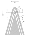
図4に示されるように、熱交換器20は、第1熱交換器41および第2熱交換器42が第2方向D2に沿って並べられる構成を有する。第1熱交換器41の第1方向D1に沿った長さは、第2熱交換器42の第1方向D1に沿った長さと等しい。第2方向D2から見た場合に、第1熱交換器41の第1方向D1の端部の位置と、第2熱交換器42の第1方向D1の端部の位置とは、等しい。第1方向D1から見た場合に、第1熱交換器41は、第2熱交換器42の外側に位置する。言い換えると、第1熱交換器41の上端は、第2熱交換器42の上端よりも高い位置にある。第1熱交換器41は、冷媒配管25を介して第2熱交換器42と接続されている。
As shown in FIG. 4, the
複数の第1扁平管231はそれぞれ、180度未満の1つの第1折り曲げ部231cを挟んで、1つの第1部231aおよび1つの第2部231bを有する。複数の第2扁平管232はそれぞれ、180度未満の1つの第2折り曲げ部232cを挟んで、1つの第3部232aおよび1つの第4部232bを有する。第1部231aおよび第2部231bはそれぞれ、第3部232aおよび第4部232bを覆うように配置される。図4~6に示されるように、第1部231aおよび第3部232aは、第1方向D1から見た場合に所定の方向に延びる。第2部231bおよび第4部232bは、第1方向D1から見た場合に、第1部231aおよび第3部232aが延びる方向とは異なる所定の方向に延びる。第1折り曲げ部231cは、図4に示されるように、第1方向D1から見た場合に第1部231aが延びる方向と第2部231bが延びる方向との間の角度αが180度未満となるように、折り曲げられる。第1折り曲げ部231cは、角度αが90度以下となるように、折り曲げられてもよい。第2折り曲げ部232cは、第1方向D1から見た場合に第3部232aが延びる方向と第4部232bが延びる方向との間の角度βが180度未満となるように、折り曲げられる。第2折り曲げ部232cは、角度βが90度以下となるように、折り曲げられてもよい。
Each of the first
複数の第1扁平管231の第1部231a側の端部には、第1ヘッダー21aが取り付けられる。複数の第1扁平管231の第2部231b側の端部には、第2ヘッダー21bが取り付けられる。複数の第1扁平管231は、第1ヘッダー21aおよび第2ヘッダー21bよりも上方に第1折り曲げ部231cが位置するように配置される。そのため、図4に示されるように、複数の第1扁平管231は、第1方向D1から見た場合に、180°回転させたV字型形状を有する。同様に、複数の第2扁平管232の第3部232a側の端部には、第3ヘッダー21cが取り付けられる。複数の第2扁平管232の第4部232b側の端部には、第4ヘッダー21dが取り付けられる。複数の第2扁平管232は、第3ヘッダー21cおよび第4ヘッダー21dよりも上方に第2折り曲げ部232cが位置するように配置される。そのため、図4に示されるように、複数の第2扁平管232は、第1方向D1から見た場合に、180°回転させたV字型形状を有する。
A
第1部231a、第2部231b、第3部232a、および第4部232bは、冷媒が通過する複数の通路を有する扁平多穴管である。第1部231aおよび第3部232aの複数の通路は、第1方向D1から見た場合に、第1部231aおよび第3部232aが延びる方向に直交する方向に沿って並んで配置される。第2部231bおよび第4部232bの複数の通路は、第1方向D1から見た場合に、第2部231bおよび第4部232bが延びる方向に直交する方向に沿って並んで配置される。図5~6に示されるように、第1折り曲げ部231cは、第1部231aの複数の通路と第2部231bの複数の通路とを連通するように、一部が湾曲している扁平多穴管である。第2折り曲げ部232cは、第3部232aの複数の通路と第4部232bの複数の通路とを連通するように、一部が湾曲している扁平多穴管である。
The
第1部231a、第2部231b、第3部232a、および第4部232bは、図4~6に示されるように、主表面が第2方向D2および第3方向D3に沿うように配置される。第1部231a、第2部231b、第3部232a、および第4部232bは、主表面と直交する第1方向D1に沿って、所定の間隔を空けて配置される。
The
(2-1-2)第1伝熱フィンおよび第2伝熱フィン
第1伝熱フィン261は、複数の第1扁平管231の内部を流れる冷媒と、送風装置30が生成する空気の流れと、の間の熱交換を促す。第2伝熱フィン262は、複数の第2扁平管232の内部を流れる冷媒と、送風装置30が生成する空気の流れと、の間の熱交換を促す。第1伝熱フィン261および第2伝熱フィン262は、コルゲートフィンである。第1伝熱フィン261および第2伝熱フィン262は、アルミニウムまたはアルミニウム合金を素材する。
(2-1-2) First heat transfer fin and second heat transfer fin The first
図4に示されるように、第1伝熱フィン261は、第1方向D1に沿って隣り合う複数の第1扁平管231の間において、第1部231aおよび第2部231bに対して固定される。より詳細には、第1伝熱フィン261は、第1方向D1に沿って隣り合う第1部231aの間に設けられる。第1伝熱フィン261は、波型の頂点が第1部231aの主表面に固定されることにより第1部231aに対して固定される。また、第1伝熱フィン261は、第1方向D1に沿って隣り合う第2部231bの間にも設けられる。第1伝熱フィン261は、波型の頂点が第2部231bの主表面に固定されることにより第2部231bに対して固定される。同様に、第2伝熱フィン262は、第1方向D1に沿って隣り合う複数の第2扁平管232の間において、第3部232aおよび第4部232bに対して固定される。より詳細には、第2伝熱フィン262は、第1方向D1に沿って隣り合う第3部232aの間に設けられる。第2伝熱フィン262は、波型の頂点が第3部232aの主表面に固定されることにより第3部232aに対して固定される。また、第2伝熱フィン262は、第1方向D1に沿って隣り合う第4部232bの間にも設けられる。第2伝熱フィン262は、波型の頂点が第4部232bの主表面に固定されることにより第4部232bに対して固定される。
As shown in FIG. 4, the first
(2-1-3)第1ヘッダー、第2ヘッダー、第3ヘッダー、および第4ヘッダー
第1ヘッダー21aおよび第2ヘッダー21bは、複数の第1扁平管231の両端に取り付けられる。具体的には、第1ヘッダー21aは、複数の第1扁平管231の第1部231a側の端部に取り付けられる。第2ヘッダー21bは、複数の第1扁平管231の第2部231b側の端部に取り付けられる。第1ヘッダー21aおよび第2ヘッダー21bは、第1方向D1に延びるように配置される。同様に、第3ヘッダー21cおよび第4ヘッダー21dは、複数の第2扁平管232の両端に取り付けられる。具体的には、第3ヘッダー21cは、複数の第2扁平管232の第3部232a側の端部に取り付けられる。第4ヘッダー21dは、複数の第2扁平管232の第4部232b側の端部に取り付けられる。
(2-1-3) First Header, Second Header, Third Header, and Fourth Header The
第1ヘッダー21a、第2ヘッダー21b、第3ヘッダー21c、および第4ヘッダー21dは、第1方向D1に延びるように配置される。第1ヘッダー21a、第2ヘッダー21b、第3ヘッダー21c、および第4ヘッダー21dは、ドレンパン24の上方に配置される。第1ヘッダー21a、第2ヘッダー21b、第3ヘッダー21c、および第4ヘッダー21dは、冷媒配管25を介して外部の冷媒回路に接続される。
The
図4に示されるように、第1方向D1から見た場合の第1部231aが延びる方向に直交する方向において、第1部231aの幅W1は、第1ヘッダー21aの幅W2より小さい。第2部231bおよび第2ヘッダー21bにおいても同様である。第1方向D1から見た場合の第3部232aが延びる方向に直交する方向において、第3部232aの幅W3は、第3ヘッダー21cの幅W4より小さい。第4部232bおよび第4ヘッダー21dにおいても同様である。これにより、第1熱交換器41と第2熱交換器42との間に、隙間が生じる。
As shown in FIG. 4, in a direction perpendicular to the direction in which the
(2-2)遮蔽部材
図7に示されるように、遮蔽部材50は、第1方向D1に沿って延びるブロック状の部材である。遮蔽部材50は、例えば、樹脂を素材とする。遮蔽部材50は、第1折り曲げ部231cと第2折り曲げ部232cとの隙間に配置される。遮蔽部材50の第1方向D1に沿った長さは、第1熱交換器41と第2熱交換器42の第1方向D1に沿った長さと等しい。
(2-2) Shielding Member As shown in Fig. 7, the shielding
(2-3)サイドパネル
図7に示されるように、サイドパネル60は、略三角形の形状を有する平板である。サイドパネル60は、例えば、樹脂を素材とする。エアハンドリングユニット100は、一組のサイドパネル60を有する。一組のサイドパネル60は、第1熱交換器41および第2熱交換器42を第1方向D1に沿って挟み込むように、第1熱交換器41および第2熱交換器42の第1方向D1の端部に取り付けられる。サイドパネル60は、送風装置30が生成する空気の流れが、第1熱交換器41と第2熱交換器42との隙間から漏れることを防止する。
(2-3) Side Panel As shown in Fig. 7,
図9に示されるように、サイドパネル60の、第1熱交換器41および第2熱交換器42側の第1面61には、第1凹部91、第2凹部92、および第3凹部93が形成される。図10,11に示されるように、第1凹部91には、第1熱交換器41の第1方向D1の端部が挿入される。第2凹部92には、第2熱交換器42の第1方向D1の端部が挿入される。第3凹部93には、遮蔽部材50の第1方向D1の端部が挿入される。
As shown in FIG. 9, a
(2-4)ドレンパン
ドレンパン24は、第1ヘッダー21a、第2ヘッダー21b、第3ヘッダー21c、および第4ヘッダー21d側に配置される。具体的には、ドレンパン24は、第1ヘッダー21a、第2ヘッダー21b、第3ヘッダー21c、および第4ヘッダー21dの下方に配置される。ドレンパン24は、第1熱交換器41および第2熱交換器42からの結露水を受ける。具体的には、ドレンパン24は、複数の第1扁平管231、複数の第2扁平管232、第1ヘッダー21a、第2ヘッダー21b、第3ヘッダー21c、および第4ヘッダー21dからの結露水を受ける。結露水とは、複数の第1扁平管231、および複数の第2扁平管232の内部を流れる冷媒と、熱交換室17を通過する空気との間の熱交換により、複数の第1扁平管231、複数の第2扁平管232、第1ヘッダー21a、第2ヘッダー21b、第3ヘッダー21c、および第4ヘッダー21dの表面に発生する水である。発生した結露水は、自重により、複数の第1扁平管231、複数の第2扁平管232、第1ヘッダー21a、第2ヘッダー21b、第3ヘッダー21c、および第4ヘッダー21dの表面を伝って流下して、ドレンパン24に受けられる。ドレンパン24は、支持部材12に固定されている。
(2-4) Drain Pan The
ドレンパン24は、図11~13に示されるように、第1壁24aと、第2壁24bと、受け部24cと、排水口24dと、を有する。第2方向D2から見た場合に、ドレンパン24は、略長方形の形状を有する。
As shown in Figures 11 to 13, the
第1壁24aは、熱交換室17を第2方向D2に流れる空気が通過する開口部24fを囲む。言い換えると、ドレンパン24は、送風装置30が生成する空気の流れを通過させる開口部24fを有する。開口部24fは、ドレンパン24を第2方向D2から見た場合に、ドレンパン24の中央部に位置する。開口部24fは、第2方向D2から見た場合に、略長方形の形状を有する。熱交換室17を第2方向D2に流れる空気は、開口部24fを通過して送風室18に流入する。第2壁24bは、ドレンパン24を第2方向D2から見た場合に、第1壁24aの外側に位置する。
The
受け部24cは、第1壁24aの下端部と、第2壁24bの下端部とを接続する。受け部24cは、ドレンパン24の底部に相当する。受け部24cは、第1ヘッダー21a、第2ヘッダー21b、第3ヘッダー21c、および第4ヘッダー21dの下方に配置される。第1壁24aと、第2壁24bと、受け部24cとによって囲まれる空間は、結露水を受けてドレン水として一時的に貯留するための空間である。排水口24dは、第2壁24bに形成される。排水口24dは、ドレンパン24を第2方向D2から見た場合に、ドレンパン24の長方形の形状の角部に形成される。排水口24dは、ドレンパン24の外部にドレン水を排出するための穴である。
The receiving
受け部24cは、図13に示されるように、第1壁24aから第2壁24bに向かって下り勾配となるように傾斜する上面である第1面24eを有する。言い換えると、ドレンパン24を第2方向D2から見た場合に、受け部24cは、第1壁24aがある中央側から、第2壁24bがある外側に向かって、第1面24eの高さ位置が低下する部分を有する。第1面24eは、ドレンパン24の底面に相当する。第1面24eは、ドレン水が接触する面である。
As shown in FIG. 13, the receiving
第1面24eは、少なくとも、第1方向D1に沿って延びる第1壁24aと、第1方向D1に沿って延びる第2壁24bとの間において傾斜していればよい。言い換えると、少なくとも、第1ヘッダー21a、第2ヘッダー21b、第3ヘッダー21c、および第4ヘッダー21dの下方に位置する第1面24eが、第3方向D3において、第1壁24aから第2壁24bに向かって下り勾配となるように傾斜していればよい。
The
受け部24cは、図11~12に示されるように、第1面24eから突出する突起部24jを有する。突起部24jは、図4に示されるように、第1ヘッダー21a、第2ヘッダー21b、第3ヘッダー21c、および第4ヘッダー21dを支持する。
The receiving
(3)特徴
(3-1)
従来、効率的に熱交換を行うため、熱交換器にサイドパネルを取り付け、熱交換器を通過する空気の流れが熱交換部以外の場所から漏れることを防止する技術がある。
(3) Features (3-1)
2. Description of the Related Art In the past, in order to perform efficient heat exchange, there has been a technique for attaching a side panel to a heat exchanger to prevent the air flow passing through the heat exchanger from leaking from any place other than the heat exchange portion.
熱交換器が第1熱交換器および第2熱交換器を備え、第1熱交換器が第2熱交換器を覆うように配置される場合、第1熱交換器と第2熱交換器との隙間から空気の流れが漏れる恐れがある。 If the heat exchanger includes a first heat exchanger and a second heat exchanger, and the first heat exchanger is positioned to cover the second heat exchanger, there is a risk of air leaking from the gap between the first and second heat exchangers.
本実施形態のエアハンドリングユニット100は、第1熱交換器41と、第2熱交換器42と、送風装置30と、を備える。第1熱交換器41は、複数の第1扁平管231と、第1伝熱フィン261と、第1ヘッダー21aと、第2ヘッダー21bと、を有する。複数の第1扁平管231は、180度未満の第1折り曲げ部231cを挟んで第1部231aおよび第2部231bを有する。複数の第1扁平管231は、第1方向D1に沿って並ぶ。第1伝熱フィン261は、隣り合う複数の第1扁平管231の間に設けられる。第1ヘッダー21aは、複数の第1扁平管231の第1部231a側の端部に取り付けられる。第2ヘッダー21bは、複数の第1扁平管231の第2部231b側の端部に取り付けられる。第2熱交換器42は、複数の第2扁平管232と、第2伝熱フィン262と、第3ヘッダー21cと、第4ヘッダー21dと、を有する。複数の第2扁平管232は、180度未満の第2折り曲げ部232cを挟んで第3部232aおよび第4部232bを有する。複数の第2扁平管232は、第1方向D1に沿って並ぶ。第2伝熱フィン262は、隣り合う複数の第2扁平管232の間に設けられる。第3ヘッダー21cは、複数の第2扁平管232の第3部232a側の端部に取り付けられる。第4ヘッダー21dは、複数の第2扁平管232の第4部232b側の端部に取り付けられる。送風装置30は、第1熱交換器41および第2熱交換器42を通過する空気の流れを生成する。第1部231aおよび第2部231bはそれぞれ、第3部232aおよび第4部232bを覆うように配置される。エアハンドリングユニット100は、サイドパネル60をさらに備える。サイドパネル60は、第1熱交換器41の第1方向D1の端部に取り付けられる。サイドパネル60は、送風装置30が生成する空気の流れが、第1熱交換器41と第2熱交換器42との隙間から漏れることを防止する。
The
エアハンドリングユニット100では、サイドパネル60は、送風装置30が生成する空気の流れが、第1熱交換器41と第2熱交換器42との隙間から漏れることを防止する。その結果、エアハンドリングユニット100は、効率的に熱交換を行うことができる。
In the
(3-2)
エアハンドリングユニット100では、第1方向D1から見た場合の第1部231aが延びる方向に直交する方向において、第1部231aの幅W1は、第1ヘッダー21aの幅W2より小さい。第1方向D1から見た場合の第3部232aが延びる方向に直交する方向において、第3部232aの幅W3は、第3ヘッダー21cの幅W4より小さい。
(3-2)
In
(3-3)
エアハンドリングユニット100では、サイドパネル60は、平板である。サイドパネル60の第1熱交換器41側の第1面61には、第1凹部91が形成される。第1凹部91には、第1熱交換器41の第1方向D1の端部が挿入される。
(3-3)
In
エアハンドリングユニット100は、第1熱交換器41の第1方向D1の端部を第1凹部91に挿入することにより、第1熱交換器41の位置を決定し、第1熱交換器41を固定することができる。また、エアハンドリングユニット100は、送風装置30が生成する空気の流れが、第1熱交換器41と第2熱交換器42との隙間から漏れることをより効果的に防止することができる。
The
(3-4)
エアハンドリングユニット100では、サイドパネル60は、第2熱交換器42の第1方向D1の端部に取り付けられる。サイドパネル60の第1面61には、第2凹部92が形成される。第2凹部92には、第2熱交換器42の第1方向D1の端部が挿入される。
(3-4)
In
エアハンドリングユニット100は、第2熱交換器42の第1方向D1の端部を第2凹部92に挿入することにより、第2熱交換器42の位置を決定し、第2熱交換器42を固定することができる。また、エアハンドリングユニット100は、送風装置30が生成する空気の流れが、第1熱交換器41と第2熱交換器42との隙間から漏れることをより効果的に防止することができる。
The
(3-5)
エアハンドリングユニット100は、遮蔽部材50をさらに備える。遮蔽部材50は、第1折り曲げ部231cと第2折り曲げ部232cとの隙間に配置される。サイドパネル60の第1熱交換器41側の第1面61には、第3凹部93が形成される。第3凹部93には、遮蔽部材50の第1方向D1の端部が挿入される。
(3-5)
エアハンドリングユニット100は、遮蔽部材50の第1方向D1の端部を第3凹部93に挿入することにより、遮蔽部材50の位置を決定し、遮蔽部材50を固定することができる。また、エアハンドリングユニット100は、送風装置30が生成する空気の流れが、第1折り曲げ部231cと第2折り曲げ部232cとの隙間から漏れることを防止することができる。
The
(3-6)
エアハンドリングユニット100は、ドレンパン24をさらに備える。ドレンパン24は、第1熱交換器41および第2熱交換器42からの結露水を受ける。ドレンパン24は、第1ヘッダー21a、第2ヘッダー21b、第3ヘッダー21c、および第4ヘッダー21d側に配置される。ドレンパン24は、開口部24fを有する。開口部24fは、送風装置30が生成する空気の流れを通過させる。
(3-6)
(4)変形例
(4-1)変形例1A
エアハンドリングユニット100は、熱交換室17と、送風室18との位置を入れ替えて設置されてもよい。図14に示されるエアハンドリングユニット101は、エアハンドリングユニット100において、熱交換室17と、送風室18との位置を入れ替えたものである。送風装置30によって生成される空気は、吸込口13から吹出口14に向かって、ケーシング11の内部空間を鉛直方向上向きに流れる。
(4) Modifications (4-1) Modification 1A
(4-2)変形例1B
本実施形態では、エアハンドリングユニット100は、ケーシング11の長手方向が鉛直方向に沿うように、縦置きにして設置された。しかし、エアハンドリングユニット100は、ケーシング11の長手方向が水平方向に沿うように、横置きにして設置されてもよい。図15に示されるエアハンドリングユニット102は、第1方向D1から見た場合に、エアハンドリングユニット100を90°回転させたものである。送風装置30によって生成される空気は、吸込口13から吹出口14に向かって、ケーシング11の内部空間を水平方向に流れる。
(4-2) Modification 1B
In this embodiment,
エアハンドリングユニット102は、第2のドレンパン27と、支持部材28と、をさらに備える。第2のドレンパン27は、熱交換器20の下方に配置される。第2のドレンパン27は、第1熱交換器41および第2熱交換器42の表面から自重によって落下した結露水を受ける。支持部材28は、サイドパネル60と第2のドレンパン27とを接続する。第1熱交換器41および第2熱交換器42は、サイドパネル60および支持部材28により、第2のドレンパン27に固定される。
The
その結果、エアハンドリングユニット102は、サイドパネル60および支持部材28を利用して、第1熱交換器41および第2熱交換器42を、第2のドレンパン27に固定することができる。
As a result, the
エアハンドリングユニット102は、熱交換室17と、送風室18との位置を入れ替えて設置されてもよい。図16に示されるエアハンドリングユニット103は、エアハンドリングユニット102において、熱交換室17と、送風室18との位置を入れ替えたものである。送風装置30によって生成される空気は、吸込口13から吹出口14に向かって、ケーシング11の内部空間を水平方向に流れる。
The
(4-3)変形例1C
本実施形態では、第1熱交換器41の第1方向D1に沿った長さは、第2熱交換器42の第1方向D1に沿った長さと等しかった。しかし、図17に示されるように、第1熱交換器41の第1方向D1に沿った長さは、第2熱交換器42の第1方向D1に沿った長さより長くてもよい。第2方向D2から見た場合に、第2熱交換器42の第1方向D1の端部は、第1熱交換器41の内側に位置する。
(4-3) Modification 1C
In this embodiment, the length of the
このとき、例えば、一組のサイドパネル60が、第1熱交換器41を第1方向D1に沿って挟み込むように、第1熱交換器41の第1方向D1の端部に取り付けられ、他の一組のサイドパネル80が、第2熱交換器42を第1方向D1に沿って挟み込むように、第2熱交換器42の第1方向D1の端部に取り付けられる。サイドパネル60の第1熱交換器41側の第1面61には、第1凹部91が形成される。サイドパネル80の第2熱交換器42側の第1面81には、第2凹部92が形成される。
In this case, for example, one set of
第1熱交換器41の第1方向D1に沿った長さ、または第2熱交換器42の第1方向D1に沿った長さは、スペーサによって調整されてもよい。スペーサは、第1熱交換器41または第2熱交換器42の第1方向D1の端部に取り付けられる。このとき、サイドパネル60、またはサイドパネル80は、スペーサに取り付けられる。
The length of the
(4-4)変形例1D
本実施形態では、サイドパネル60の、第1熱交換器41および第2熱交換器42側の第1面61には、第1凹部91、第2凹部92、および第3凹部93が形成された。しかし、第1凹部91、第2凹部92、および第3凹部93の代わりに、サイドパネル60の、第1熱交換器41および第2熱交換器42側の第1面61には、図18に示されるように、第1凸部71、第4凸部74、および第7凸部77が形成されてもよい。
(4-4) Modification 1D
In this embodiment, a
図18に示されるように、第1凸部71は、第1熱交換器41の第1方向D1の端部の形状に沿う。第1凸部71は、第2凸部72と、第3凸部73と、を有する。第2凸部72は、第1熱交換器41の第1方向D1の端部における第2熱交換器42側の形状に沿う。第3凸部73は、第1熱交換器41の第1方向D1の端部における、第2熱交換器42とは反対側の形状に沿う。図19,20に示されるように、エアハンドリングユニット100は、第1熱交換器41の第1方向D1の端部を第2凸部72と第3凸部73との間に挿入することにより、第1熱交換器41の位置を決定し、第1熱交換器41を固定することができる。また、エアハンドリングユニット100は、送風装置30が生成する空気の流れが、第1熱交換器41と第2熱交換器42との隙間から漏れることをより効果的に防止することができる。
As shown in FIG. 18, the first
図18に示されるように、第4凸部74は、第2熱交換器42の第1方向D1の端部の形状に沿う。第4凸部74は、第5凸部75と、第6凸部76と、を有する。第5凸部75は、第2熱交換器42の第1方向D1の端部における、第1熱交換器41とは反対側の形状に沿う。第6凸部76は、第2熱交換器42の第1方向D1の端部における第1熱交換器41側の形状に沿う。図19,20に示されるように、エアハンドリングユニット100は、第2熱交換器42の第1方向D1の端部を第5凸部75と第6凸部76との間に挿入することにより、第2熱交換器42の位置を決定し、第2熱交換器42を固定することができる。また、エアハンドリングユニット100は、送風装置30が生成する空気の流れが、第1熱交換器41と第2熱交換器42との隙間から漏れることをより効果的に防止することができる。
As shown in FIG. 18, the fourth
図18に示されるように、第7凸部77は、遮蔽部材50の第1方向D1の端部の形状に沿う。図19,20に示されるように、エアハンドリングユニット100は、遮蔽部材50の第1方向D1の端部を第7凸部77に囲まれた空間に挿入することにより、遮蔽部材50の位置を決定し、遮蔽部材50を固定することができる。また、エアハンドリングユニット100は、送風装置30が生成する空気の流れが、第1折り曲げ部231cと第2折り曲げ部232cとの隙間から漏れることを防止することができる。
As shown in FIG. 18, the seventh
なお、第1凹部91、および第2凹部92が形成されている、サイドパネル60の、第1熱交換器41および第2熱交換器42側の第1面61に、第3凹部93の代わりに、第7凸部77が形成されてもよい。また、第1凸部71、および第4凸部74が形成されている、サイドパネル60の、第1熱交換器41および第2熱交換器42側の第1面61に、第7凸部77の代わりに、第3凹部93が形成されてもよい。
In addition, a seventh
(4-5)
以上、本開示の実施形態を説明したが、特許請求の範囲に記載された本開示の趣旨および範囲から逸脱することなく、形態や詳細の多様な変更が可能なことが理解されるであろう。
(4-5)
Although the embodiments of the present disclosure have been described above, it will be understood that various changes in form and details can be made without departing from the spirit and scope of the present disclosure described in the claims.
21a~21d 第1ヘッダー~第4ヘッダー
24 ドレンパン(第1のドレンパン)
24f 開口部
27 第2のドレンパン
28 支持部材
30 送風装置
41,42 第1熱交換器、第2熱交換器
50 遮蔽部材(第2部材)
60 サイドパネル(第1部材)
61 第1面
71~77 第1凸部~第7凸部
91~93 第1凹部~第3凹部
100~103 エアハンドリングユニット
231,232 複数の第1扁平管、複数の第2扁平管
231a,231b 第1部、第2部
231c,232c 第1折り曲げ部、第2折り曲げ部
232a,232b 第3部、第4部
261,262 第1伝熱フィン、第2伝熱フィン
D1 第1方向
W1~W4 幅
21a to 21d First header to
24f opening 27
60 Side panel (first member)
61 First surface 71-77 First to seventh convex portions 91-93 First to third concave portions 100-103
Claims (10)
180度未満の第2折り曲げ部(232c)を挟んで第3部(232a)および第4部(232b)を有する、前記第1方向に沿って並ぶ複数の第2扁平管(232)と、隣り合う前記複数の第2扁平管の間に設けられる第2伝熱フィン(262)と、前記複数の第2扁平管の前記第3部側の端部に取り付けられる第3ヘッダー(21c)と、前記複数の第2扁平管の前記第4部側の端部に取り付けられる第4ヘッダー(21d)と、を有する第2熱交換器(42)と、
前記第1熱交換器および前記第2熱交換器を通過する空気の流れを生成する送風装置(30)と、
を備え、
前記第1部および前記第2部はそれぞれ、前記第3部および前記第4部を覆うように配置され、
前記第1熱交換器の前記第1方向の端部に取り付けられ、前記送風装置が生成する空気の流れが、前記第1熱交換器と前記第2熱交換器との隙間から漏れることを防止する第1部材(60)、
をさらに備える、
エアハンドリングユニット(100~103)。 a first heat exchanger (41) including: a plurality of first flat tubes (231) arranged along a first direction (D1), the first flat tubes (231) having a first portion (231a) and a second portion (231b) sandwiched between a first bend portion (231c) of less than 180 degrees; first heat transfer fins (261) provided between adjacent first flat tubes; a first header (21a) attached to ends of the first flat tubes on the first portion side; and a second header (21b) attached to ends of the first flat tubes on the second portion side;
a second heat exchanger (42) including: a plurality of second flat tubes (232) arranged along the first direction, the second flat tubes (232) having a third portion (232a) and a fourth portion (232b) sandwiched between a second bent portion (232c) of less than 180 degrees; second heat transfer fins (262) provided between adjacent second flat tubes; a third header (21c) attached to ends of the plurality of second flat tubes on the third portion side; and a fourth header (21d) attached to ends of the plurality of second flat tubes on the fourth portion side;
A blower (30) for generating an air flow passing through the first heat exchanger and the second heat exchanger;
Equipped with
the first portion and the second portion are disposed to cover the third portion and the fourth portion, respectively;
a first member (60) attached to an end of the first heat exchanger in the first direction and preventing the air flow generated by the blower device from leaking through a gap between the first heat exchanger and the second heat exchanger;
Further comprising:
Air handling unit (100-103).
前記第1方向から見た場合の前記第3部が延びる方向に直交する方向において、前記第3部の幅(W3)は、前記第3ヘッダーの幅(W4)より小さい、
請求項1に記載のエアハンドリングユニット(100~103)。 In a direction perpendicular to the direction in which the first portion extends when viewed from the first direction, the width (W1) of the first portion is smaller than the width (W2) of the first header,
In a direction perpendicular to the direction in which the third portion extends when viewed from the first direction, the width (W3) of the third portion is smaller than the width (W4) of the third header,
An air handling unit (100-103) according to claim 1.
前記第1部材の前記第1熱交換器側の第1面(61)には、前記第1熱交換器の前記第1方向の端部が挿入される第1凹部(91)が形成される、
請求項1または2に記載のエアハンドリングユニット(100~103)。 the first member is a flat plate,
A first recess (91) into which an end portion of the first heat exchanger in the first direction is inserted is formed on a first surface (61) of the first member on the first heat exchanger side.
An air handling unit (100-103) according to claim 1 or 2.
前記第1部材の前記第1面には、前記第2熱交換器の前記第1方向の端部が挿入される第2凹部(92)が形成される、
請求項3に記載のエアハンドリングユニット。 The first member is attached to an end portion of the second heat exchanger in the first direction,
A second recess (92) into which an end portion of the second heat exchanger in the first direction is inserted is formed on the first surface of the first member.
4. The air handling unit of claim 3.
前記第1部材の前記第1熱交換器側の第1面(61)には、前記第1熱交換器の前記第1方向の端部の形状に沿って第1凸部(71)が形成され、
前記第1凸部は、前記第1熱交換器の前記第1方向の端部における前記第2熱交換器側の形状に沿った第2凸部(72)と、前記第1熱交換器の前記第1方向の端部における、前記第2熱交換器とは反対側の形状に沿った第3凸部(73)と、を有する、
請求項1または2に記載のエアハンドリングユニット(100~103)。 the first member is a flat plate,
A first convex portion (71) is formed on a first surface (61) of the first member on the first heat exchanger side along the shape of an end portion of the first heat exchanger in the first direction,
The first convex portion has a second convex portion (72) that follows the shape of the second heat exchanger side at the end of the first heat exchanger in the first direction, and a third convex portion (73) that follows the shape of the opposite side to the second heat exchanger at the end of the first heat exchanger in the first direction.
An air handling unit (100-103) according to claim 1 or 2.
前記第1部材の前記第1面には、前記第2熱交換器の前記第1方向の端部の形状に沿って第4凸部(74)が形成され、
前記第4凸部は、前記第2熱交換器の前記第1方向の端部における、前記第1熱交換器とは反対側の形状に沿った第5凸部(75)と、前記第2熱交換器の前記第1方向の端部における前記第1熱交換器側の形状に沿った第6凸部(76)と、を有する、
請求項5に記載のエアハンドリングユニット。 The first member is attached to an end portion of the second heat exchanger in the first direction,
A fourth convex portion (74) is formed on the first surface of the first member along the shape of an end portion of the second heat exchanger in the first direction,
The fourth convex portion has a fifth convex portion (75) that follows the shape of the side opposite to the first heat exchanger at the end of the second heat exchanger in the first direction, and a sixth convex portion (76) that follows the shape of the first heat exchanger at the end of the second heat exchanger in the first direction.
6. An air handling unit according to claim 5.
をさらに備え、
前記第1部材の前記第1熱交換器側の第1面(61)には、前記第2部材の前記第1方向の端部が挿入される第3凹部(93)が形成される、
請求項1から6のいずれか1つに記載のエアハンドリングユニット(100~103)。 a second member (50) disposed in a gap between the first folded portion and the second folded portion;
Further equipped with
A third recess (93) into which an end portion of the second member in the first direction is inserted is formed on a first surface (61) of the first member on the first heat exchanger side.
An air handling unit (100-103) according to any one of the preceding claims.
をさらに備え、
前記第1部材の前記第1熱交換器側の第1面(61)には、前記第2部材の前記第1方向の端部の形状に沿った第7凸部(77)が形成される、
請求項1から6のいずれか1つに記載のエアハンドリングユニット(100~103)。 a second member (50) disposed in a gap between the first folded portion and the second folded portion;
Further equipped with
A seventh convex portion (77) is formed on a first surface (61) of the first member on the first heat exchanger side, the seventh convex portion (77) being aligned with the shape of an end portion of the second member in the first direction.
An air handling unit (100-103) according to any one of the preceding claims.
をさらに備え、
前記第1のドレンパンは、
前記第1ヘッダー、前記第2ヘッダー、前記第3ヘッダー、および前記第4ヘッダー側に配置され、
前記送風装置が生成する空気の流れを通過させる開口部(24f)を有する、
請求項1から8のいずれか1つに記載のエアハンドリングユニット(100~103)。 a first drain pan (24) for receiving condensation water from the first heat exchanger and the second heat exchanger;
Further equipped with
The first drain pan comprises:
Located on the first header, the second header, the third header, and the fourth header side,
The air blower has an opening (24f) through which the air flow generated by the air blower passes.
An air handling unit (100-103) according to any one of the preceding claims.
前記第1部材と前記第2のドレンパンとを接続する支持部材(28)と、
をさらに備え、
前記第1熱交換器は、前記第1部材および前記支持部材により、前記第2のドレンパンに固定される、
請求項9に記載のエアハンドリングユニット(102,103)。 a second drain pan (27) for receiving condensed water from the first heat exchanger and the second heat exchanger;
A support member (28) that connects the first member and the second drain pan;
Further equipped with
The first heat exchanger is fixed to the second drain pan by the first member and the support member.
10. An air handling unit (102, 103) according to claim 9.
Applications Claiming Priority (2)
| Application Number | Priority Date | Filing Date | Title |
|---|---|---|---|
| JP2023170893 | 2023-09-29 | ||
| JP2023-170893 | 2023-09-29 |
Publications (1)
| Publication Number | Publication Date |
|---|---|
| WO2025070763A1 true WO2025070763A1 (en) | 2025-04-03 |
Family
ID=95203199
Family Applications (1)
| Application Number | Title | Priority Date | Filing Date |
|---|---|---|---|
| PCT/JP2024/034758 Pending WO2025070763A1 (en) | 2023-09-29 | 2024-09-27 | Air handling unit |
Country Status (1)
| Country | Link |
|---|---|
| WO (1) | WO2025070763A1 (en) |
Citations (3)
| Publication number | Priority date | Publication date | Assignee | Title |
|---|---|---|---|---|
| US5341870A (en) * | 1985-10-02 | 1994-08-30 | Modine Manufacturing Company | Evaporator or evaporator/condenser |
| WO2016084185A1 (en) * | 2014-11-27 | 2016-06-02 | 三菱電機株式会社 | Heat-exchanging unit and air conditioning apparatus |
| CN205561589U (en) * | 2016-02-03 | 2016-09-07 | 浙江盾安热工科技有限公司 | Heat exchanger with micro -channels |
-
2024
- 2024-09-27 WO PCT/JP2024/034758 patent/WO2025070763A1/en active Pending
Patent Citations (3)
| Publication number | Priority date | Publication date | Assignee | Title |
|---|---|---|---|---|
| US5341870A (en) * | 1985-10-02 | 1994-08-30 | Modine Manufacturing Company | Evaporator or evaporator/condenser |
| WO2016084185A1 (en) * | 2014-11-27 | 2016-06-02 | 三菱電機株式会社 | Heat-exchanging unit and air conditioning apparatus |
| CN205561589U (en) * | 2016-02-03 | 2016-09-07 | 浙江盾安热工科技有限公司 | Heat exchanger with micro -channels |
Similar Documents
| Publication | Publication Date | Title |
|---|---|---|
| AU2008321997B2 (en) | Indoor unit for air conditioner | |
| JP6615316B2 (en) | Finless type heat exchanger, outdoor unit of air conditioner equipped with the finless type heat exchanger, and indoor unit of air conditioner equipped with the finless type heat exchanger | |
| CN102047064A (en) | Heat exchanger | |
| CN103998869A (en) | Outdoor unit for refrigeration device | |
| CN108885015A (en) | indoor heat exchanger | |
| JP5338883B2 (en) | Heat source unit | |
| CN108613285A (en) | Package AC plant | |
| WO2025070763A1 (en) | Air handling unit | |
| JP2005133966A (en) | Heat exchanger | |
| KR20050012223A (en) | Front suction/discharge type outdoor unit for air conditioner | |
| WO2025070719A1 (en) | Heat exchange unit and air handling unit | |
| JP2025060265A (en) | Heat exchange unit and air handling unit | |
| KR101392069B1 (en) | Out-Door Unit of Air Conditioner | |
| CN116724209A (en) | heat exchanger | |
| JPS6018767Y2 (en) | Air conditioner outdoor unit | |
| CN216448282U (en) | A net cover bracket and an air conditioner outdoor unit | |
| JP2002162060A (en) | Air conditioner | |
| CN218328462U (en) | Energy storage cabinet chilled water air conditioner | |
| WO2025070808A1 (en) | Heat exchanger and air handling unit | |
| CN216522080U (en) | Air condensing units and air conditioner | |
| CN218495222U (en) | Energy storage cabinet cold water air conditioner | |
| CN217383114U (en) | Indoor machine of air conditioner | |
| CN218120043U (en) | Energy storage cabinet cold water air conditioner | |
| KR100377412B1 (en) | Heat exchanger | |
| CN216769573U (en) | Cabinet Air Conditioner |
Legal Events
| Date | Code | Title | Description |
|---|---|---|---|
| 121 | Ep: the epo has been informed by wipo that ep was designated in this application |
Ref document number: 24872544 Country of ref document: EP Kind code of ref document: A1 |