WO2024247065A1 - 細胞培養容器及び細胞培養方法 - Google Patents
細胞培養容器及び細胞培養方法 Download PDFInfo
- Publication number
- WO2024247065A1 WO2024247065A1 PCT/JP2023/019978 JP2023019978W WO2024247065A1 WO 2024247065 A1 WO2024247065 A1 WO 2024247065A1 JP 2023019978 W JP2023019978 W JP 2023019978W WO 2024247065 A1 WO2024247065 A1 WO 2024247065A1
- Authority
- WO
- WIPO (PCT)
- Prior art keywords
- cell
- cell culture
- adhesive region
- culture
- culture vessel
- Prior art date
- Legal status (The legal status is an assumption and is not a legal conclusion. Google has not performed a legal analysis and makes no representation as to the accuracy of the status listed.)
- Ceased
Links
Images


Classifications
-
- C—CHEMISTRY; METALLURGY
- C12—BIOCHEMISTRY; BEER; SPIRITS; WINE; VINEGAR; MICROBIOLOGY; ENZYMOLOGY; MUTATION OR GENETIC ENGINEERING
- C12M—APPARATUS FOR ENZYMOLOGY OR MICROBIOLOGY; APPARATUS FOR CULTURING MICROORGANISMS FOR PRODUCING BIOMASS, FOR GROWING CELLS OR FOR OBTAINING FERMENTATION OR METABOLIC PRODUCTS, i.e. BIOREACTORS OR FERMENTERS
- C12M3/00—Tissue, human, animal or plant cell, or virus culture apparatus
-
- C—CHEMISTRY; METALLURGY
- C12—BIOCHEMISTRY; BEER; SPIRITS; WINE; VINEGAR; MICROBIOLOGY; ENZYMOLOGY; MUTATION OR GENETIC ENGINEERING
- C12N—MICROORGANISMS OR ENZYMES; COMPOSITIONS THEREOF; PROPAGATING, PRESERVING, OR MAINTAINING MICROORGANISMS; MUTATION OR GENETIC ENGINEERING; CULTURE MEDIA
- C12N5/00—Undifferentiated human, animal or plant cells, e.g. cell lines; Tissues; Cultivation or maintenance thereof; Culture media therefor
- C12N5/06—Animal cells or tissues; Human cells or tissues
-
- C—CHEMISTRY; METALLURGY
- C12—BIOCHEMISTRY; BEER; SPIRITS; WINE; VINEGAR; MICROBIOLOGY; ENZYMOLOGY; MUTATION OR GENETIC ENGINEERING
- C12N—MICROORGANISMS OR ENZYMES; COMPOSITIONS THEREOF; PROPAGATING, PRESERVING, OR MAINTAINING MICROORGANISMS; MUTATION OR GENETIC ENGINEERING; CULTURE MEDIA
- C12N5/00—Undifferentiated human, animal or plant cells, e.g. cell lines; Tissues; Cultivation or maintenance thereof; Culture media therefor
- C12N5/10—Cells modified by introduction of foreign genetic material
Definitions
- This disclosure relates to a cell culture vessel and a cell culture method.
- Cell culture is often performed using adhesion culture.
- the containers used for adhesion culture are usually made of polystyrene (PS) and are manufactured by injection molding.
- PS polystyrene
- PE polyethylene
- Patent Document 1 discloses a method for culturing adherent cells, in which a bag-shaped container having a container wall that serves as a cell culture surface is pressed to increase the internal pressure, thereby suppressing the flow of liquid contents, encouraging the adherent cells to adhere to the cell culture surface, or culturing the adherent cells while suppressing detachment of the adhered cells.
- Patent Document 1 also discloses that adherent cells can be cultured using a bag-shaped container made of a material to which adherent cells have difficulty adhering and having a container wall that has not been surface-treated to improve cell adhesion, that a bag-shaped container having a cell culture surface that has been surface-treated and has a container wall to which adhesive cells can easily adhere may be used, and that the surface treatment is a treatment in which the surface of a resin film or the like that constitutes the container wall is irradiated with ultraviolet light, corona discharge, plasma discharge, electron beams, or other high-energy electromagnetic waves or particle beams to make it hydrophilic.
- PE bag-shaped cell culture vessels have the advantage that they can be easily molded into a sealed shape, even when they are large.
- the cell adhesion surface may not be flat. In such cases, the cells will not grow uniformly, causing variations in cell density and making it difficult to maintain cell quality.
- Patent Document 1 uses a method that allows cell culture even on surfaces that have not been treated with a surface treatment to improve cell adhesion, and does not specify how the treated and untreated surfaces should be arranged.
- the objective of this disclosure is to provide a cell culture vessel that allows desired cells to be cultured on desired surfaces while preventing cell growth on other surfaces.
- the cell culture vessel of the present disclosure is bag-shaped, and the inner surface of the cell culture vessel is provided with a cell adhesive region that forms a flat cell culture surface, and a cell non-adhesive region, the cell adhesive region is provided on the surface that forms the bottom surface, and the inner surface surfaces whose normals are vertically upward and other than the cell adhesive region are cell non-adhesive regions.
- the present disclosure provides a cell culture vessel that allows desired cells to be cultured on a desired surface while preventing cell growth on other surfaces.
- FIG. 2 is a top view showing the cell culture vessel of Example 1. This is a cross-sectional view of B-B' in Figure 1A.
- FIG. 11 is a top view showing a cell culture vessel of Example 2. This is a cross-sectional view of B-B' in Figure 2A.
- FIG. 11 is a top view showing the cell culture vessel of Example 3.
- FIG. 13 is a top view showing the cell culture vessel of Example 4. This is a cross-sectional view of B-B' in Figure 4A.
- FIG. 4C is a cross-sectional view showing the cell culture vessel of FIG. 4B in a folded state.
- FIG. 13 is a top view showing the cell culture vessel of Example 5. This is a cross-sectional view of B-B' in Figure 5A.
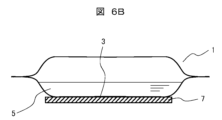
- FIG. 13 is a top view showing a cell culture vessel of Example 6. This is a cross-sectional view of B-B' in Figure 6A.
- FIG. 1A is a top view showing the cell culture vessel of Example 1.
- the culture bag 1 (cell culture vessel) shown in this diagram is a resin bag, and is formed from a material that is easily deformed. The periphery of the bag is sealed by heat welding or the like (sealing portion 11).
- a port 4 for introducing and evacuating liquid or gas is attached to the culture bag 1.
- a culture fluid storage area 2 is formed inside the culture bag 1.
- a cell adhesive area 3, shown by a dashed line, is provided on the inner surface of the culture bag 1, in the center of the storage area 2.
- the cell adhesive area 3 is a portion of the inner surface of the culture bag 1 that has been subjected to a hydrophilic treatment.
- the inner surface of the culture bag 1 other than the cell adhesive area 3 has not been subjected to a hydrophilic treatment and is therefore non-cell adhesive.
- the non-cell adhesive surface of the inner surface is referred to as the "non-cell adhesive area.”
- FIG. 1B is a cross-sectional view taken along line B-B' in FIG. 1A.
- the cell adhesive region 3 constitutes the flat portion of the culture bag 1 during use.
- culture fluid 5 and a specific gas are injected into the culture bag 1. This causes the culture bag 1 to expand, and the portion between the cell adhesive region 3 and the sealing portion 11 becomes an inclined curved portion 12.
- the surface of the inner surface of the culture bag 1 that is located above the culture fluid 5 is in contact with the gas, but is not in contact with the culture fluid 5.
- the cells supplied together with the culture medium 5 settle and adhere to the flat cell adhesive region 3 when the culture bag 1 is left stationary.
- the grown cells then have the desired uniform morphology and characteristics.
- the curved portion 12 and the like are non-cell adhesive, so the cells do not settle there, and the growth of undesirable cells can be suppressed.
- the material suitable for the culture bag 1 should be easy to process, such as by heat welding, and have strength.
- resins such as polyolefin resins, styrene elastomers, polyester thermoplastic elastomers, silicone thermoplastic elastomers, silicone resins, and ethylene-vinyl acetate copolymer resins (EVA) are suitable.
- the cell adhesive region 3 is created by, for example, performing plasma treatment, corona discharge treatment, etc. on the hydrophobic resin that is the material of the culture bag 1, which has non-cell adhesive properties. By performing these surface treatments on the desired surface of the hydrophobic resin, it is possible to impart appropriate hydrophilicity and make it cell adhesive.
- the surface that has been given hydrophilicity by the above surface treatment becomes the cell adhesive region 3, and the surface that has not been subjected to the surface treatment becomes a cell non-adhesive region.
- a coating of a resin or the like that is more hydrophobic than the resin may be formed on the surface of the resin.
- Culture bag 1 is prepared by the following method.
- a portion of a resin film that is non-cell-adhesive and hydrophobic is subjected to a surface treatment to make it cell-adhesive.
- the culture bag 1 from polyethylene (PE).
- PE polyethylene
- the portion of the inner surface of the PE that will become the cell adhesive region 3 is appropriately treated to be hydrophilic.
- the contact angle is preferably 60 to 90 degrees.
- the user can culture with either side of the culture bag 1 facing up.
- the culture fluid 5 may come into contact with the surface of the inner surface of the culture bag 1 that will become the ceiling surface, but it is preferable to inject gas to prevent contact.
- the culture bag 1 is used without providing a gas phase inside the culture bag 1, and is filled with culture fluid 5.
- the culture fluid 5 comes into contact with the inner surface of the culture bag 1 that will become the ceiling surface, but when cells are seeded, they fall to the upward surface (bottom surface) due to gravity, and therefore the cells do not settle on the downward surface (ceiling surface) even if the downward surface has cell adhesive properties. For this reason, cells do not grow on the downward surface, and defects are unlikely to occur.
- gas necessary for cell culture may be dissolved in the culture fluid 5 beforehand.
- the culture bag 1 of this embodiment is bag-shaped, and the inner surface of the culture bag 1 is provided with a cell adhesive region 3 that serves as a flat cell culture surface, and a cell non-adhesive region.
- the cell adhesive region 3 is provided on the surface that serves as the bottom surface.
- the surfaces whose normals are vertically upward and that are other than the cell adhesive region 3 are cell non-adhesive regions.
- a surface whose normals are vertically upward refers to a surface whose normal vector has a vertical component that faces upward.
- FIG. 2A is a top view showing the cell culture vessel of Example 2.
- a cell adhesive plate 23 having at least a flat upper surface and cell adhesive properties is attached to the inner surface of the culture bag 1.
- the same surface treatment as in Example 1 can be used to impart cell adhesive properties to the cell adhesive plate 23.
- the cell adhesive plate 23 is formed from a material that is difficult to deform.
- the cell adhesive region is composed of a flat cell adhesive plate 23.
- Figure 2B is a cross-sectional view taken along line B-B' in Figure 2A.
- the cell adhesive plate 23 has dimensions equal to or smaller than the flat surface of the culture bag 1 when the culture bag 1 contains the culture fluid 5. It is also desirable that the cell adhesive plate 23 is fixed tightly to the inner surface of the culture bag 1 with no gaps. This is to prevent cells from getting between the bottom surface of the cell adhesive plate 23 and the inner surface of the culture bag 1, which would result in the cells being cultured in the uneven area and thus causing a decrease in cell quality.
- the cell adhesive plate 23 can be fixed using a method such as thermal welding or ultrasonic welding.
- the material of the cell adhesion plate 23 is preferably strong, has little distortion, and is not cytotoxic. Furthermore, if the material is transparent, it is even more preferable because this allows cells to be observed from below.
- resin materials such as polystyrene, polycarbonate, polyester resin, acrylic resin, nylon resin, acrylonitrile-styrene resin, and silicone resin are suitable.
- Corrosion-resistant metals titanium, gold alloys, stainless steel, etc. may also be used, but because they are disposable, it is desirable that they are low-cost and lightweight from the viewpoint of work. For this reason, resin materials are suitable.
- the culture bag 1 from polyethylene (PE) and the cell adhesion plate 23 from polystyrene (PS).
- PE polyethylene
- PS polystyrene
- the part of the inner surface of the PS that will become the cell culture surface is appropriately treated to be hydrophilic.
- the contact angle is preferably 60 to 90 degrees.
- the cell adhesive plate 23 which is not easily deformed, can be fixed in the desired position without performing a surface treatment on the material of the non-cell-adhesive culture bag 1, so the culture bag 1 can be used even if the installation position is not flat.
- FIG. 3A is a top view showing the cell culture vessel of Example 3.
- Figure 3B is a cross-sectional view taken along line B-B' in Figure 3A.
- the cell adhesion plates 23a, 23b are placed one on top of the other. At least the upper surfaces of the cell adhesion plates 23a, 23b are flat and have cell adhesive properties.
- the cell adhesion plate 23a is attached to the inner surface of the culture bag 1.
- the cell adhesion plate 23b is placed on four pillars 8 provided on the upper surface of the cell adhesion plate 23a. This leaves a gap between the cell adhesion plate 23a and the cell adhesion plate 23b. It is desirable to adjust the amount of culture solution 5 placed in the culture bag 1 so that the depth of the culture solution 5 above the cell adhesion plate 23b is approximately the same as the height of the gap. This is to ensure that the cells contained in the culture solution 5 settle and settle on each of the cell adhesion plates 23a, 23b at an equal density.
- the method for imparting cell adhesive properties to the cell adhesion plates 23a and 23b is the same as in Example 1.
- a culture medium 5 (cell suspension) in which the cells are uniformly dispersed is introduced into the culture bag 1 and left to stand. After a while, the cells sink to the bottom, attach to the spot, and begin to grow. Therefore, the number of cells that attach to the bottom is proportional to the amount of cell suspension present above the bottom.
- two cell adhesion plates are stacked, but three or more cell adhesion plates may be stacked.
- the cell adhesive region has a configuration in which multiple cell adhesive plates are stacked, with gaps provided between the multiple cell adhesive plates. Furthermore, when three or more cell adhesive plates are stacked, there will be multiple gaps. Furthermore, it is desirable for the spacing between each of the multiple cell adhesive plates to be approximately equal.
- This configuration allows cells to be seeded at a uniform density on the top cell adhesion plate and on each of the other cell adhesion plates.
- a large amount of cells can be cultured in a single culture bag 1.
- FIG. 4A is a top view showing the cell culture vessel of Example 4.
- Figure 4B is a cross-sectional view of B-B' in Figure 4A, showing the state without culture medium or gas.
- FIG. 4C is a cross-sectional view showing the cell culture vessel of FIG. 4B in a folded state.
- the culture bag 1 can be folded. This allows the culture bag 1 to be compact for transportation and storage. It can also be stored in a small space.
- the dimensions of the cell adhesion plates 23c, 23d can be made small, damage and deformation of the cell adhesion plates 23c, 23d can be prevented, and there is also the advantage that it is easy to transport.
- the cell adhesive region has a configuration in which multiple divided cell adhesive plates are arranged on the bottom surface. Also, the cell culture vessel is configured so that it can be folded so that the multiple cell adhesive plates overlap.
- FIG. 5A is a top view showing the cell culture vessel of Example 5.
- Figure 5B is a cross-sectional view taken along line B-B' in Figure 5A.
- the culture bag 1 has a configuration similar to that of Example 1.
- a fixture 6 having a recess with a flat bottom surface is placed outside the culture bag 1, and the culture bag 1 is placed in the recess of the fixture 6, thereby flattening the cell adhesive region 3.
- the fixing device 6 is preferably made of a highly rigid material such as metal, ceramic, or hard plastic.
- the surface of the fixing device 6 that comes into contact with the culture bag 1 is preferably flat.
- the culture fluid 5 is poured into the culture bag 1, and the weight of the culture fluid 5 is used to bring the fixing device 6 and the culture bag 1 into close contact, making the cell adhesive region 3 of the culture bag 1 into a flat surface.
- the peripheral portion of the recess of the fixing device 6 is sloped, so the culture bag 1 can be fixed in place.
- the fixing device 6 prefferably has a shape similar to the shape of the culture bag 1 when the culture solution 5 is contained in the culture bag 1.
- the fixing device 6 has a recess with a flat bottom surface, and the cell adhesive region 3 is placed on the fixing device 6 so as to face the bottom surface of the recess.
- Example 5 instead of the cell adhesive region 3, a cell adhesive plate 23 may be attached to the inner surface of the culture bag 1 as in Example 2. Similarly, a cell adhesive plate as in Example 3 or 4 may be used.
- Example 5 Even when combining Example 5 with any of the configurations of Examples 2 to 4, it is desirable to make the area of the cell adhesion plate smaller than the area of the bottom surface of the recess in the fixture 6 so that the cell adhesion plate fits into said bottom surface. Furthermore, if the area of the cell adhesion plate is made approximately equal to the area of the bottom surface of the recess in the fixture 6, the cell adhesion plate can be fitted into the fixture 6 without any gaps, and displacement of the cell adhesion plate can be prevented.
- the position of the culture bag 1 can be stabilized during use.
- FIG. 6A is a top view showing the cell culture vessel of Example 6.
- Figure 6B is a cross-sectional view of B-B' in Figure 6A.
- a cell adhesive region 3 is provided on the inner surface of the culture bag 1, and a flat plate 7 is attached to the outer surface of the culture bag 1, which is the reverse side of the cell adhesive region 3, to make the cell adhesive region 3 flat. It is desirable to make the area of the cell adhesive region 3 smaller than the area of the flat plate 7. This is because the entire cell adhesive region 3 is made flat by the flat plate 7. This allows the desired cells to be cultured in the cell adhesive region 3.
- the flat plate 7 is preferably made of a highly rigid material such as metal, ceramic, or hard plastic.
- the surface of the flat plate 7 that comes into contact with the culture bag 1 is preferably flat.
- the plate 7 can be fixed using a thermal welding method, ultrasonic welding method, or the like. It may also be attached using an adhesive material or glue. For example, an adhesive material such as silicone rubber may be evenly sandwiched between the metal plate 7 and the culture bag 1.
- the flat plate 7 may be attached to the culture bag 1 immediately before the culture bag 1 is used, or may be attached to the culture bag 1 in advance.
- the cell culture vessel may be configured so that the flat plate 7 can be attached to the outer surface of the cell culture vessel located on the back side of the cell adhesive region 3, or the flat plate 7 may be provided on the outer surface of the cell culture vessel located on the back side of the cell adhesive region 3.
- the cell culture method disclosed herein includes a step of seeding cells, such as iPS cells, in the cell culture vessel of any of the above examples, and a step of adhering the cells to the cell adhesive region and culturing them. This method allows desired cells to be cultured on a desired surface, while preventing cell growth on other surfaces.
- 1 culture bag
- 2 storage area
- 3 cell adhesive area
- 4 port
- 5 culture medium
- 6 fixture
- 7 flat plate
- 11 sealing part
- 12 curved part
- 23, 23a, 23b, 23c, 23d cell adhesive plate.
Landscapes
- Life Sciences & Earth Sciences (AREA)
- Engineering & Computer Science (AREA)
- Health & Medical Sciences (AREA)
- Wood Science & Technology (AREA)
- Biomedical Technology (AREA)
- Organic Chemistry (AREA)
- Bioinformatics & Cheminformatics (AREA)
- Chemical & Material Sciences (AREA)
- Zoology (AREA)
- Cell Biology (AREA)
- Sustainable Development (AREA)
- Microbiology (AREA)
- Biotechnology (AREA)
- Biochemistry (AREA)
- General Engineering & Computer Science (AREA)
- General Health & Medical Sciences (AREA)
- Genetics & Genomics (AREA)
- Virology (AREA)
- Apparatus Associated With Microorganisms And Enzymes (AREA)
Abstract
袋状の細胞培養容器であって、細胞培養容器の内面には、平坦な細胞培養面となる細胞接着性領域と、細胞非接着性領域と、が設けられ、細胞接着性領域は、底面となる面に設けられ、内面のうち、法線が鉛直上向きとなる面であって細胞接着性領域以外の面は、細胞非接着性領域である。これにより、所望の面において所望の細胞を培養するとともに、それ以外の面においては細胞の成長を防止する細胞培養容器を提供することができる。
Description
本開示は、細胞培養容器及び細胞培養方法に関する。
細胞培養は、多くの場合、接着培養で行われる。接着培養に用いる容器(細胞培養容器)は、通常、ポリスチレン(PS)製であり、射出成形によって製造される。一方、細胞培養容器としては、ポリエチレン(PE)製の袋状のものも使用されている。
特許文献1には、細胞培養面となる容器壁を備えた袋状容器を押圧して内圧を上昇させることで液状収容物の流動を抑制し、接着性細胞が細胞培養面に接着することを促し、または、接着した細胞が剥離することを抑制しながら接着性細胞を培養する、接着性細胞の培養方法が開示されている。また、特許文献1には、袋状容器として、接着性細胞が接着し難い材料からなり、細胞の接着性を向上する表面処理が施されていない容器壁を備えたものを使用し、接着性細胞を培養し得ること、細胞培養面を表面処理し、接着性細胞が接着し易い容器壁を備えた袋状容器を使用してもよいこと、表面処理は、容器壁を構成する樹脂フィルム等の表面に、紫外線照射、コロナ放電、プラズマ放電、電子線などの高エネルギーの電磁波や粒子線を照射して親水性とする処理であることが開示されている。
射出成形によって製造されるPS製の細胞培養容器は、大量培養をめざして培養容器サイズを大きくする場合、成形用の金型が大きくなり、製造コストが高くなるだけでなく、細胞培養容器の底面における歪みが大きくなる等の問題がある。
PE製の袋状の細胞培養容器は、大型であっても、密閉形状の成形が容易であるという利点がある。しかしながら、PE製の袋は、軟らかい素材であるため、細胞接着面が平坦にならない場合がある。その場合、細胞の育ち方が一様でなくなり、細胞の密度にばらつきが生じ、細胞品質を保つことが難しくなるという問題がある。
細胞接着面を平坦にしたとしても、平坦な面の周囲には、傾斜した面や湾曲した面等が生じるため、これらの面に細胞が付着した場合、望ましくない性質を有する細胞ができる場合や、細胞の成長が不十分となる場合があること、iPS細胞を培養する場合に所望の細胞と異なる細胞になる場合があること等の問題が生じるおそれがある。
特許文献1においては、細胞の接着性を向上する表面処理が施されていない面であっても培養が可能な方法を用いているため、表面処理を施した面と施していない面とをどのように配置するかについては具体的に特定していない。
細胞培養における上記の問題が生じないようにするためには、湾曲している面等の細胞培養に不適切な面には細胞が接着しにくくすることが重要と考えられる。
本開示の目的は、所望の面において所望の細胞を培養するとともに、それ以外の面においては細胞の成長を防止する細胞培養容器を提供することにある。
本開示の細胞培養容器は、袋状であって、細胞培養容器の内面には、平坦な細胞培養面となる細胞接着性領域と、細胞非接着性領域と、が設けられ、細胞接着性領域は、底面となる面に設けられ、内面のうち、法線が鉛直上向きとなる面であって細胞接着性領域以外の面は、細胞非接着性領域である。
本開示によれば、所望の面において所望の細胞を培養するとともに、それ以外の面においては細胞の成長を防止する細胞培養容器を提供することができる。
以下、本開示に係る実施例について、図面を用いて説明する。
図1Aは、実施例1の細胞培養容器を示す上面図である。
本図に示す培養バッグ1(細胞培養容器)は、樹脂製の袋であり、変形しやすい材料で形成されている。袋の周縁部は、熱溶着等により封止されている(封止部11)。培養バッグ1には、液体又は気体を出し入れするためのポート4が取り付けられている。培養バッグ1の内部には、培養液の収容領域2が形成されている。収容領域2の中央部であって培養バッグ1の内面には、破線で示す細胞接着性領域3が設けられている。細胞接着性領域3は、培養バッグ1の内面であって親水処理が施された部分である。細胞接着性領域3以外の培養バッグ1の内面は、親水処理をしていないため、細胞非接着性である。ここで、当該内面のうち、細胞非接着性の面は、「細胞非接着性領域」と呼ぶ。
図1Bは、図1AのB-B’断面図である。
図1Bに示すように、細胞接着性領域3は、使用時には、培養バッグ1の平坦部を構成している。使用時には、培養バッグ1の内部に培養液5が注入され、所定の気体が注入されている。これにより、培養バッグ1が膨らみ、細胞接着性領域3と封止部11との間の部分が斜面状の湾曲部12になっている。また、培養バッグ1の内面のうち、培養液5の上方に位置する面は、気体と接触し、培養液5とは接触していない。
このような構成により、培養液5とともに供給された細胞が、培養バッグ1を静置した状態で平坦な細胞接着性領域3に沈降して付着する。そして、成長した細胞は、一様な形態及び特性を有する所望のものになる。一方、湾曲部12等は、細胞非接着性としているため、細胞が定着することがなく、望ましくない細胞の成長を抑制することができる。
培養バッグ1の材料は、熱溶着等の加工が容易で、かつ、強度を有するものが適している。例えば、ポリオレフィン系樹脂、スチレン系エラストマー、ポリエステル系熱可塑性エラストマー、シリコーン系熱可塑性エラストマー、シリコーン樹脂、エチレン-酢酸ビニル共重合樹脂(EVA)等の樹脂が好適である。
細胞接着性領域3は、細胞非接着性を有する培養バッグ1の材料である疎水性の樹脂に、例えば、プラズマ処理、コロナ放電処理等を施すことにより作製する。これらの表面処理を疎水性の樹脂の所望の面に施すことにより、適度な親水性を付与し、細胞接着性とすることができるからである。上記の表面処理を施して親水性を付与した面は、細胞接着性領域3となり、表面処理を施していない面は、細胞非接着性の領域となる。
更に確実に細胞非接着性の領域を設けるためには、樹脂の表面にその樹脂よりも疎水性が高い樹脂等の被膜を形成してもよい。
培養バッグ1は、次の方法により作製する。
(1)細胞非接着性であり、かつ、疎水性である樹脂製のフィルムの一部に細胞接着性にするための表面処理を施す。
(2)表面処理を施したフィルムと表面処理を施していないフィルムとを合わせ、四辺を熱溶着等により接合する。この際、表面処理を施した面を内側にして合わせる。また、送液、排液、送気、排気等を行うためのポートも所定の位置に挟み込んで一緒に接合する。
例えば、培養バッグ1をポリエチレン(PE)で形成すれば、コスト及び加工性の観点から望ましい。PEの内面のうち細胞接着性領域3となる部分は、適度に親水処理を施す。接触角は、60~90度が望ましい。
なお、上記の表面処理は、接合する二枚のフィルムの両方(培養バッグ1の内面となる面)に行えば、ユーザーが培養バッグ1のどちらの面を上向きにしても培養ができる。この場合、培養液5は、培養バッグ1の内面のうち、天井面となる側の面に接触してもよいが、接触しないように気体を注入することが望ましい。
培養バッグ1の内部に気相を設けずに、培養バッグ1を培養液5で満たした状態で培養バッグ1を使用する場合もある。この場合、培養液5は、培養バッグ1の内面のうち、天井面となる側の面に接触するが、細胞を播種した際には、細胞は、重力により上向きの面(底面)に落下するため、下向きの面(天井面)においては、細胞接着性を有していても、細胞が定着することがない。このため、下向きの面で細胞が成長することはなく、不具合が生じることは少ない。なお、この場合、培養液5には、細胞の培養に必要な気体をあらかじめ溶解してもよい。
まとめると、本実施例の培養バッグ1は、袋状であって、培養バッグ1の内面には、平坦な細胞培養面となる細胞接着性領域3と、細胞非接着性領域と、が設けられている。細胞接着性領域3は、底面となる面に設けられている。そして、培養バッグ1の内面のうち、法線が鉛直上向きとなる面であって細胞接着性領域3以外の面は、細胞非接着性領域である。ここで、法線が鉛直上向きとなる面とは、当該面の法線ベクトルの鉛直方向の成分が上向きに設置される面をいう。
本実施例によれば、培養バッグ1の細胞接着性領域3において所望の細胞を培養するとともに、それ以外の面においては細胞の成長を防止することができる。
図2Aは、実施例2の細胞培養容器を示す上面図である。
本図においては、実施例1(図1A)の細胞接着性領域3に代えて、少なくとも上面が平坦で細胞接着性を有する細胞接着板23を培養バッグ1の内面に貼付した構成を有する。細胞接着板23に細胞接着性を付与する方法としては、実施例1と同様の表面処理を用いることができる。細胞接着板23は、変形しにくい材料で形成されている。
言い換えると、細胞接着性領域は、平板である細胞接着板23で構成されている。
図2Bは、図2AのB-B’断面図である。
図2Bに示すように、細胞接着板23は、培養バッグ1に培養液5を入れた状態で、培養バッグ1が平坦になる面と同等又はそれよりも小さい寸法を有することが望ましい。そして、細胞接着板23は、培養バッグ1の内面に隙間なく密着させて固定することが望ましい。細胞接着板23の下面と培養バッグ1の内面との間に細胞が入り込み、平坦でない部分で細胞が培養されることになり、細胞品質が低下することを防止するためである。この場合に、細胞接着板23の固定には、熱溶着法、超音波溶着法等を用いることができる。
細胞接着板23の材料としては、強度があり歪みが少ないものであって細胞毒性がないものが好適である。また、透明であれば、下方からの細胞観察が可能となるため更に好適である。
具体的には、ポリスチレン、ポリカーボネート、ポリエステル系樹脂、アクリル樹脂、ナイロン樹脂、アクリロニトリルスチレン樹脂、シリコーン樹脂等の樹脂材料が好適である。腐食しにくい金属(チタン、金等の合金、ステンレス鋼等)を用いてもよいが、使い捨てであるため、低コストであること、作業の観点から軽量であることが望まれる。このため、樹脂材料が好適である。
例えば、培養バッグ1をポリエチレン(PE)、細胞接着板23をポリスチレン(PS)で形成すれば、コスト及び加工性の観点から望ましい。PSの内面のうち細胞培養面となる部分は、適度に親水処理を施す。接触角は、60~90度が望ましい。
本実施例において、上記以外の構成は、実施例1と同様であるため、説明を省略する。
本実施例によれば、細胞非接着性の培養バッグ1の材料に表面処理を施すことなく、変形しにくい細胞接着板23を所望の位置に固定して用いるため、培養バッグ1の設置位置が平坦でなくても使用することができる。また、培養バッグ1の歪みを防止するための構成を設ける必要がなく、その手間も必要がなく、細胞の培養を行うことができる。
図3Aは、実施例3の細胞培養容器を示す上面図である。
図3Bは、図3AのB-B’断面図である。
これらの図に示すように、本実施例においては、細胞接着板23a、23bを重ねて設置している。細胞接着板23a、23bは、少なくとも上面が平坦で細胞接着性を有する。細胞接着板23aは、培養バッグ1の内面に貼付している。細胞接着板23bは、細胞接着板23aの上面に設けた四個の柱8の上に設置されている。これにより、細胞接着板23aと細胞接着板23bとの間に隙間が設けられている。培養バッグ1に入れる培養液5の量は、細胞接着板23bの上方の培養液5が当該隙間の高さと同程度の深さとなるようにすることが望ましい。培養液5に含まれる細胞が沈降して細胞接着板23a、23bのそれぞれに定着する密度を等しくするためである。
なお、細胞接着板23a、23bに細胞接着性を付与する方法は、実施例1と同様である。
ここで、細胞播種の方法について説明する。
細胞を播種する際には、細胞を均一に分散させた培養液5(細胞懸濁液)を培養バッグ1に導入し、静置する。しばらくすると、細胞が底面に沈み、その場に付着して成長を始める。そのため、底面に付着する細胞の数は、その底面の上方に存在する細胞懸濁液の量に比例する。
したがって、細胞接着板23a、23bに一様に細胞が播種されるためには、細胞接着板23a、23bの間隔をその面内において一定とすることが望ましい。そして、細胞接着板23bの上方の細胞懸濁液の深さがその面内において一定であって当該間隔と等しくなるようにすることが望ましい。
上記の例においては、細胞接着板を二枚重ねた場合を示しているが、細胞接着板を三枚以上重ねた構成であってもよい。この場合には、重ねた細胞接着板のそれぞれの間の間隔を等しくすることが望ましい。そして、最上段の細胞接着板の上方の細胞懸濁液の深さがその面内において一定であって当該間隔と等しくなるようにすることが望ましい。
まとめると、細胞接着性領域は、細胞接着板を複数重ねた構成を有し、複数の細胞接着板の間には、隙間が設けられている。また、細胞接着板を三枚以上重ねた構成の場合、当該隙間は、複数となる。そして、複数の細胞接着板のそれぞれの間隔は、略等しいことが望ましい。
このような構成により、最上段の細胞接着板及びそれ以外の細胞接着板のそれぞれに一様な細胞密度で播種することができる。
本実施例において、上記以外の構成は、実施例2と同様であるため、説明を省略する。
本実施例によれば、一個の培養バッグ1で大量の細胞を培養することができる。
図4Aは、実施例4の細胞培養容器を示す上面図である。
本図に示す培養バッグ1においては、二個に分割した細胞接着板23c、23dを培養バッグ1の内面に貼付している。
図4Bは、図4AのB-B’断面図であり、培養液や気体を入れていない状態を示したものである。
図4Cは、図4Bの細胞培養容器を折りたたんだ状態を示す断面図である。
図4Cのように二個に分割された細胞接着板23c、23dが設けられているため、培養バッグ1は、折りたたむことができる。このため、培養バッグ1をコンパクトにして輸送や保管をすることができる。また、狭い場所にも収納することができる。また、細胞接着板23c、23dのそれぞれの寸法を小さくできるため、細胞接着板23c、23dの破損や変形を防止することができ、輸送がしやすいという利点もある。
本実施例において、上記以外の構成は、実施例2と同様であるため、説明を省略する。
まとめると、細胞接着性領域は、複数に分割された細胞接着板を底面となる面に並べた構成を有する。また、細胞培養容器は、複数の細胞接着板が重なるように折りたたむことができるように構成されている。
図5Aは、実施例5の細胞培養容器を示す上面図である。
図5Bは、図5AのB-B’断面図である。
図5Aに示すように、培養バッグ1は、実施例1のものと同様の構成を有する。
本実施例においては、図5Bに示すように、凹部を有し凹部の底面が平坦である固定具6を培養バッグ1の外部に設置し、固定具6の凹部に培養バッグ1を設置することにより、細胞接着性領域3を平坦にする。細胞接着性領域3の面積を当該底面の面積より小さくし、細胞接着性領域3が当該底面に収まるようにすることにより、細胞接着性領域3において所望の細胞を培養することができる。
固定具6は、金属、セラミック、硬質プラスチック等の剛性の高い材料で作製することが望ましい。固定具6が培養バッグ1に接触する面は、平坦であることが望ましい。
培養バッグ1の使用時には、培養バッグ1の内部に培養液5を入れるため、その培養液5の重さを利用して固定具6と培養バッグ1とを密着させることにより、培養バッグ1の細胞接着性領域3を平坦な面にすることができる。この場合に、固定具6の凹部の周縁部が斜面になっているため、培養バッグ1を固定することができる。
固定具6は、培養バッグ1に培養液5を入れた状態における培養バッグ1の形状に近い形状にするのが望ましい。
本実施例において、上記以外の構成は、実施例1と同様であるため、説明を省略する。
まとめると、凹部を有し凹部の底面が平坦である固定具6に、細胞接着性領域3が固定具6の凹部の底面に対向するように設置される構成を有する。
なお、実施例5において、細胞接着性領域3の代わりに、実施例2のように細胞接着板23を培養バッグ1の内面に貼付した構成としてもよい。同様に、実施例3又は4の細胞接着板を用いた構成としてもよい。
実施例5と実施例2~4のいずれかの構成とを組み合わせる場合においても、細胞接着板の面積を固定具6の凹部の底面の面積より小さくし、細胞接着板が当該底面に収まるようにすることが望ましい。また、細胞接着板の面積を固定具6の凹部の底面の面積とほぼ等しくすれば、細胞接着板を固定具6に隙間なくはめ込むことができ、細胞接着板のずれを防止することができる。
実施例5によれば、使用時において培養バッグ1の位置を安定させることができる。
図6Aは、実施例6の細胞培養容器を示す上面図である。
図6Bは、図6AのB-B’断面図である。
これらの図においては、実施例1と同様に、培養バッグ1の内面に細胞接着性領域3を設け、その面の裏側である培養バッグ1の外面に平板7を貼付することにより、細胞接着性領域3を平坦にしている。細胞接着性領域3の面積は、平板7の面積より小さくすることが望ましい。細胞接着性領域3の全体が平板7により平坦になるからである。これにより、細胞接着性領域3において所望の細胞を培養することができる。
平板7は、金属、セラミック、硬質プラスチック等の剛性の高い材料で作製することが望ましい。平板7が培養バッグ1に接触する面は、平坦であることが望ましい。
平板7の固定には、熱溶着法、超音波溶着法等を用いることができる。また、粘着性の素材や接着剤を用いて貼付してもよい。例えば、金属製の平板7と培養バッグ1との間にシリコンゴム等の粘着性素材を均一に挟み込んでもよい。
平板7は、培養バッグ1を使用する直前に培養バッグ1に貼付してもよいし、あらかじめ培養バッグ1に貼付しておいてもよい。
言い換えると、細胞接着性領域3の裏面に位置する細胞培養容器の外面に平板7を貼付することができるように構成されていてもよいし、細胞接着性領域3の裏面に位置する細胞培養容器の外面には、平板7が設けられていてもよい。
なお、本開示の細胞培養方法は、上記の実施例のいずれかの細胞培養容器に、iPS細胞等の細胞を播種する工程と、その細胞を細胞接着性領域に接着させて培養する工程と、を含むものである。この方法によれば、所望の面において所望の細胞を培養するとともに、それ以外の面においては細胞の成長を防止することができる。
1:培養バッグ、2:収容領域、3:細胞接着性領域、4:ポート、5:培養液、6:固定具、7:平板、11:封止部、12:湾曲部、23、23a、23b、23c、23d:細胞接着板。
Claims (10)
- 袋状の細胞培養容器であって、
前記細胞培養容器の内面には、
平坦な細胞培養面となる細胞接着性領域と、
細胞非接着性領域と、が設けられ、
前記細胞接着性領域は、底面となる面に設けられ、
前記内面のうち、法線が鉛直上向きとなる面であって前記細胞接着性領域以外の面は、前記細胞非接着性領域である、細胞培養容器。 - 前記細胞接着性領域は、平板である細胞接着板で構成されている、請求項1記載の細胞培養容器。
- 前記細胞接着性領域は、前記細胞接着板を複数重ねた構成を有し、
複数の前記細胞接着板の間には、隙間が設けられている、請求項2記載の細胞培養容器。 - 前記隙間が複数設けられ、
複数の前記細胞接着板のそれぞれの間隔が略等しい、請求項3記載の細胞培養容器。 - 前記細胞接着性領域は、複数に分割された前記細胞接着板を前記底面となる前記面に並べた構成を有する、請求項2記載の細胞培養容器。
- 前記細胞培養容器は、複数の前記細胞接着板が重なるように折りたたむことができるように構成されている、請求項5記載の細胞培養容器。
- 凹部を有し前記凹部の底面が平坦である固定具に、前記細胞接着性領域が前記固定具の前記凹部の前記底面に対向するように設置される構成を有する、請求項1記載の細胞培養容器。
- 前記細胞接着性領域の裏面に位置する前記細胞培養容器の外面に平板を貼付することができるように構成されている、請求項1記載の細胞培養容器。
- 前記細胞接着性領域の裏面に位置する前記細胞培養容器の外面には、平板が設けられている、請求項1記載の細胞培養容器。
- 請求項1記載の細胞培養容器に細胞を播種する工程と、
前記細胞を前記細胞接着性領域に接着させて培養する工程と、を含む、細胞培養方法。
Priority Applications (2)
| Application Number | Priority Date | Filing Date | Title |
|---|---|---|---|
| PCT/JP2023/019978 WO2024247065A1 (ja) | 2023-05-29 | 2023-05-29 | 細胞培養容器及び細胞培養方法 |
| JP2025523707A JPWO2024247065A1 (ja) | 2023-05-29 | 2023-05-29 |
Applications Claiming Priority (1)
| Application Number | Priority Date | Filing Date | Title |
|---|---|---|---|
| PCT/JP2023/019978 WO2024247065A1 (ja) | 2023-05-29 | 2023-05-29 | 細胞培養容器及び細胞培養方法 |
Publications (1)
| Publication Number | Publication Date |
|---|---|
| WO2024247065A1 true WO2024247065A1 (ja) | 2024-12-05 |
Family
ID=93657031
Family Applications (1)
| Application Number | Title | Priority Date | Filing Date |
|---|---|---|---|
| PCT/JP2023/019978 Ceased WO2024247065A1 (ja) | 2023-05-29 | 2023-05-29 | 細胞培養容器及び細胞培養方法 |
Country Status (2)
| Country | Link |
|---|---|
| JP (1) | JPWO2024247065A1 (ja) |
| WO (1) | WO2024247065A1 (ja) |
Citations (4)
| Publication number | Priority date | Publication date | Assignee | Title |
|---|---|---|---|---|
| JPH03160984A (ja) * | 1989-11-20 | 1991-07-10 | Kawasumi Lab Inc | 培養バッグ |
| JPH0698756A (ja) * | 1992-09-18 | 1994-04-12 | Nissho Corp | 付着性細胞培養用バツグ |
| JP2009027944A (ja) * | 2007-07-25 | 2009-02-12 | Fukoku Co Ltd | 接着性細胞培養用袋状容器 |
| WO2019091944A1 (en) * | 2017-11-08 | 2019-05-16 | Viscofan, S.A. | Cellularized collagen membranes into cell culture bag |
-
2023
- 2023-05-29 JP JP2025523707A patent/JPWO2024247065A1/ja active Pending
- 2023-05-29 WO PCT/JP2023/019978 patent/WO2024247065A1/ja not_active Ceased
Patent Citations (4)
| Publication number | Priority date | Publication date | Assignee | Title |
|---|---|---|---|---|
| JPH03160984A (ja) * | 1989-11-20 | 1991-07-10 | Kawasumi Lab Inc | 培養バッグ |
| JPH0698756A (ja) * | 1992-09-18 | 1994-04-12 | Nissho Corp | 付着性細胞培養用バツグ |
| JP2009027944A (ja) * | 2007-07-25 | 2009-02-12 | Fukoku Co Ltd | 接着性細胞培養用袋状容器 |
| WO2019091944A1 (en) * | 2017-11-08 | 2019-05-16 | Viscofan, S.A. | Cellularized collagen membranes into cell culture bag |
Also Published As
| Publication number | Publication date |
|---|---|
| JPWO2024247065A1 (ja) | 2024-12-05 |
Similar Documents
| Publication | Publication Date | Title |
|---|---|---|
| EP3640322B1 (en) | Cell culturing method and device | |
| US8114646B2 (en) | Method for ultrasonic cell removal | |
| JP7092235B2 (ja) | 細胞培養容器、細胞培養容器の支持治具、及び細胞培養方法 | |
| US12227725B2 (en) | Cell culturing method and device | |
| WO2013069490A1 (ja) | 細胞培養容器の製造方法 | |
| WO2018025743A1 (ja) | 容器の製造方法およびその製造装置、並びに、細胞培養容器、細胞培養方法、細胞培養容器の製造方法及び細胞培養容器の製造装置 | |
| WO2017170335A1 (ja) | 細胞培養容器、細胞培養容器の支持治具、及び細胞培養方法 | |
| JP2017085960A (ja) | 貫通孔を備える細胞培養用プレートを備える積層プレート式細胞培養器具 | |
| US20190048302A1 (en) | Cell culture vessel and jig for fixing cell culture vessel | |
| EP1431030B1 (fr) | Recipient thermoforme pour la culture de cellules | |
| WO2024247065A1 (ja) | 細胞培養容器及び細胞培養方法 | |
| US20210246405A1 (en) | Culture container, culture method, and transportation method | |
| JP7826617B2 (ja) | 細胞培養容器、細胞の製造方法、及び細胞培養容器の製造方法 | |
| US20220315879A1 (en) | Adherent cell culture vessel, and method for producing adherent cell culture vessel | |
| JP7081711B2 (ja) | 細胞培養容器、細胞培養方法、細胞培養容器の製造方法及び細胞培養容器の製造装置 | |
| JP2017085959A (ja) | 凸部を備える細胞培養用プレート及び細胞培養器具 | |
| US12122990B2 (en) | Culture container base material, culture container, and production method of culture container base material | |
| WO2018043576A1 (ja) | 細胞培養容器 | |
| WO2017111054A1 (ja) | 培養容器 | |
| JP2025531432A (ja) | ダイバータを有する傾斜面を備えるマイクロキャビティ細胞培養容器 | |
| US20250375768A1 (en) | Cell culture devices and related methods | |
| WO2023127132A1 (ja) | 細胞培養用容器 | |
| JP2023114106A (ja) | 培養容器の製造方法、及び培養容器 |
Legal Events
| Date | Code | Title | Description |
|---|---|---|---|
| 121 | Ep: the epo has been informed by wipo that ep was designated in this application |
Ref document number: 23939544 Country of ref document: EP Kind code of ref document: A1 |
|
| WWE | Wipo information: entry into national phase |
Ref document number: 2025523707 Country of ref document: JP |
|
| NENP | Non-entry into the national phase |
Ref country code: DE |