WO2024204051A1 - Non-contact input device - Google Patents
Non-contact input device Download PDFInfo
- Publication number
- WO2024204051A1 WO2024204051A1 PCT/JP2024/011674 JP2024011674W WO2024204051A1 WO 2024204051 A1 WO2024204051 A1 WO 2024204051A1 JP 2024011674 W JP2024011674 W JP 2024011674W WO 2024204051 A1 WO2024204051 A1 WO 2024204051A1
- Authority
- WO
- WIPO (PCT)
- Prior art keywords
- image
- aerial
- boundary
- display
- input device
- Prior art date
- Legal status (The legal status is an assumption and is not a legal conclusion. Google has not performed a legal analysis and makes no representation as to the accuracy of the status listed.)
- Ceased
Links
Images


Classifications
-
- G—PHYSICS
- G02—OPTICS
- G02B—OPTICAL ELEMENTS, SYSTEMS OR APPARATUS
- G02B30/00—Optical systems or apparatus for producing three-dimensional [3D] effects, e.g. stereoscopic images
- G02B30/50—Optical systems or apparatus for producing three-dimensional [3D] effects, e.g. stereoscopic images the image being built up from image elements distributed over a three-dimensional [3D] volume, e.g. voxels
- G02B30/56—Optical systems or apparatus for producing three-dimensional [3D] effects, e.g. stereoscopic images the image being built up from image elements distributed over a three-dimensional [3D] volume, e.g. voxels by projecting aerial or floating images
-
- G—PHYSICS
- G06—COMPUTING OR CALCULATING; COUNTING
- G06F—ELECTRIC DIGITAL DATA PROCESSING
- G06F3/00—Input arrangements for transferring data to be processed into a form capable of being handled by the computer; Output arrangements for transferring data from processing unit to output unit, e.g. interface arrangements
- G06F3/01—Input arrangements or combined input and output arrangements for interaction between user and computer
- G06F3/03—Arrangements for converting the position or the displacement of a member into a coded form
- G06F3/033—Pointing devices displaced or positioned by the user, e.g. mice, trackballs, pens or joysticks; Accessories therefor
- G06F3/0346—Pointing devices displaced or positioned by the user, e.g. mice, trackballs, pens or joysticks; Accessories therefor with detection of the device orientation or free movement in a three-dimensional [3D] space, e.g. 3D mice, 6-DOF [six degrees of freedom] pointers using gyroscopes, accelerometers or tilt-sensors
-
- G—PHYSICS
- G06—COMPUTING OR CALCULATING; COUNTING
- G06F—ELECTRIC DIGITAL DATA PROCESSING
- G06F3/00—Input arrangements for transferring data to be processed into a form capable of being handled by the computer; Output arrangements for transferring data from processing unit to output unit, e.g. interface arrangements
- G06F3/01—Input arrangements or combined input and output arrangements for interaction between user and computer
- G06F3/03—Arrangements for converting the position or the displacement of a member into a coded form
- G06F3/041—Digitisers, e.g. for touch screens or touch pads, characterised by the transducing means
Definitions
- the present invention relates to a non-contact input device.
- a non-contact input device that focuses an image displayed on a display unit of an image display device onto an imaging plane in the air and displays the image (hereinafter referred to as an aerial image) on the imaging plane.
- the non-contact input device disclosed in Patent Document 1 as described above has a physical frame that surrounds the imaging surface on which the aerial image is formed. This allows the user of the non-contact input device to clearly recognize the boundary between the aerial image and the background.
- a frame can get in the way when performing input operations on the aerial image, and may reduce operability.
- operability may be reduced.
- providing a physical frame within the aerial image is undesirable from the standpoint of operability.
- the object of the present invention is to provide a non-contact input device that can clearly recognize the boundaries of an aerial image and improve operability.
- a display unit an imaging unit that forms a display image of the display unit as a real image on an imaging surface in the air; and an image forming unit that forms a boundary image in at least a portion of the area around the real image or within the real image.
- the present invention provides a non-contact input device that can clearly recognize the boundaries of an aerial image and improves operability.
- FIG. 1 is a schematic cross-sectional view showing the configuration of a non-contact input device according to an embodiment of the present invention.
- FIG. 2 is a functional block diagram showing the functional configuration of the non-contact input device.
- FIG. 3 is a diagram showing the display unit and the boundary image output unit.
- FIG. 4 is a diagram showing an example of an aerial boundary image.
- FIG. 5 is a diagram showing a modified example of the aerial boundary image.
- FIG. 6 is a diagram showing a modified example of the aerial boundary image.
- FIG. 7 is a diagram showing a modified example of the aerial boundary image.
- FIG. 8 is a diagram showing a modified example of the aerial boundary image.
- FIG. 9 is a schematic diagram showing a situation in which a user is manipulating an aerial image.
- FIG. 10 is a schematic diagram showing a situation in which a user is manipulating an aerial boundary image.
- non-contact input device according to the present invention will be described in detail below with reference to the drawings. Note that the non-contact input device described below is one example of the non-contact input device according to the present invention, and the present invention is not limited to the embodiment described below.
- a non-contact input device 1 according to an embodiment of the present invention will be described with reference to FIGS.
- FIG. 1 is a schematic cross-sectional view showing the configuration of a non-contact input device 1 according to this embodiment.
- the non-contact input device 1 is a device equipped with a so-called air display.
- the air display can project information and images into the air.
- Such a non-contact input device 1 is used in various locations (stores, public facilities, medical facilities, factories, etc.) as a terminal for a user U to input information or a terminal for a user U to obtain information.
- the non-contact input device 1 may be used as an accounting terminal or a reception terminal.
- the non-contact input device 1 may also be used as an operation input terminal for inputting operation inputs to various devices.
- the Cartesian coordinate system (X, Y, Z) shown in Figure 1 may be used.
- the X direction corresponds to the front-to-rear direction of the non-contact input device 1.
- the + side of the X direction corresponds to the front side of the non-contact input device 1.
- the - side of the X direction corresponds to the rear side of the non-contact input device 1.
- the Y direction corresponds to the left-right direction and width direction of the non-contact input device 1.
- the + side of the Y direction corresponds to the left side when the non-contact input device 1 is viewed from the front.
- the - side of the Y direction corresponds to the right side when the non-contact input device 1 is viewed from the front.
- the Z direction corresponds to the up-down direction of the non-contact input device 1.
- the +Z direction corresponds to the top side of the non-contact input device 1.
- the -Z direction corresponds to the bottom side of the non-contact input device 1.
- the non-contact input device 1 includes a housing 2 , a display unit 3 , a boundary image output unit 4 , an imaging unit 5 , an input detection unit 6 , and a control unit 7 .
- the non-contact input device 1 is a so-called vertically-placed non-contact input device.
- the boundary image G1 is displayed in front of the non-contact input device 1 as shown in FIG. 1.
- the non-contact input device is not limited to a vertically-placed non-contact input device.
- the non-contact input device may be a so-called horizontally placed non-contact input device.
- a horizontally placed non-contact input device has a configuration in which the non-contact input device 1 shown in FIG. 1 is rotated 90° in the counterclockwise direction in FIG. 1.
- the border image G1 is displayed above the non-contact input device 1.
- the housing 2 is box-shaped and is a member for housing or supporting the elements 2 to 7 that constitute the non-contact input device 1.
- the housing 2 is a rectangular parallelepiped that is long in the vertical direction.
- the shape of the housing is not limited to the shape of the housing 2 of this embodiment. The shape of the housing may be appropriately determined depending on the environment in which the non-contact input device 1 is installed.
- the display unit 3 may be, for example, any of various displays (for example, a liquid crystal display) that display images.
- the display unit 3 is supported by the housing 2 via a support portion 21.
- the display unit 3 faces diagonally downward and forward toward the imaging unit 5, which will be described later.
- the display unit 3 is supported by the support unit 21 in a state in which the upper end of the display unit 3 is inclined at a predetermined angle ⁇ 1 in a direction approaching the imaging unit 5 described below with respect to a virtual line ⁇ 1 parallel to the vertical direction.
- the predetermined angle ⁇ 1 is 45°.
- the display image displayed by the display unit 3 is imaged as an aerial image G1 on the imaging surface S by the imaging unit 5 described below.
- the aerial image G1 is an example of a real image.
- the imaging surface S is a virtual area that exists in the air outside the housing 2.
- the imaging surface S may be considered as a virtual area large enough to image the aerial image G1 and aerial boundary image G2 described below.
- the area on the imaging surface S where the aerial image G1 is imaged is sometimes referred to as the aerial image area.
- the area on the imaging surface S where the aerial boundary image G2 is imaged is sometimes referred to as the boundary image area.
- the imaging surface S is a virtual area that exists at a position that is plane-symmetrical to the display unit 3 with respect to the imaging unit 5 (in other words, the virtual line ⁇ 2 ) described below.
- the virtual line ⁇ 2 is a virtual line that passes through the imaging unit 5 and is parallel to the vertical direction.
- the imaging surface S is a virtual area inclined at a predetermined angle ⁇ 2 with respect to a virtual line ⁇ 3 parallel to the vertical direction such that the upper end of the imaging surface S approaches an imaging unit 5 described below.
- the predetermined angle ⁇ 2 is 45°.
- the display operation of the display unit 3 is controlled by the control unit 7, which will be described later.
- the control process of the display unit 3 by the control unit 7 will be described later.
- the boundary image output unit 4 may be any of various displays that display the displayed boundary image or a laser device that outputs the displayed boundary image.
- the display unit 3 is supported by the housing 2 via a support portion 21.
- the boundary image output unit 4 has a rectangular frame shape and surrounds the entire outer edge of the display unit 3.
- Fig. 3 is a view of the display unit 3 and the boundary image output unit 4 as viewed from the direction indicated by the arrow A1 in Fig. 1.
- the arrow A1 in Fig. 1 is parallel to the normal direction of the display surfaces of the display unit 3 and the boundary image output unit 4.
- the border image output unit 4 faces the same direction as the display unit 3. In other words, the border image output unit 4 faces diagonally downward and forward toward the imaging unit 5.
- the boundary image output unit 4 is supported by the support unit 21 in a state in which the upper end of the boundary image output unit 4 is inclined at a predetermined angle ⁇ 1 in a direction approaching the imaging unit 5 described below with respect to a virtual line ⁇ 1 parallel to the vertical direction, similar to the display unit 3.
- the predetermined angle ⁇ 1 is 45°.
- the boundary image output unit 4 may be supported by the housing 2 via the display unit 3.
- the display boundary image output by the boundary image output unit 4 is imaged as an aerial boundary image G2 on the imaging surface S by the imaging unit 5 described below.
- the aerial boundary image G2 is an example of a boundary image.
- Fig. 4 shows an example of an aerial boundary image G2 formed on the imaging plane S when the shape of the boundary image output unit 4 is the rectangular frame shape shown in Fig. 3.
- Fig. 4 is a view of the aerial boundary image G2 as viewed from the direction indicated by the arrow A2 in Fig. 1.
- the arrow A2 in Fig. 1 is parallel to the normal direction of the aerial boundary image G2 (in other words, the imaging plane S).
- the portion marked with a diagonal grid in Fig. 4 is the aerial boundary image G2.
- the aerial boundary image G2 has a rectangular frame shape and is imaged on the imaging surface S so as to completely surround the outer edge of the aerial image G1.
- the aerial boundary image G2 is formed as a three-dimensional image on the imaging surface S, as shown in Figures 1 and 10.
- the aerial boundary image G2 has thickness.
- the user U of the non-contact input device 1 can view the aerial boundary image G2 not only from the front, but also from the left and right directions. As a result, the user U can reliably recognize the position of the aerial image G1.
- the aerial boundary image may be a two-dimensional image formed on the imaging surface S.
- the aerial boundary image G2 may have a plurality of regions R1, R2 for operation instructions.
- the regions R1, R2 for operation instructions are regions for a user U (see FIG. 1) of the non-contact input device 1 to input operation inputs.
- a function is assigned to each of the regions R1, R2 for operation instructions.
- a first function for switching the display mode of the display unit 3 (for example, a function for enlarging the display image of the display unit 3) may be assigned to the operation instruction area R1.
- the first function is realized.
- a second function for switching the display mode of the display unit 3 (for example, a function for reducing the display image of the display unit 3) may be assigned to the operation instruction area R2.
- the second function is realized.
- the aerial boundary image G2 not only functions as a boundary image showing the boundary between the aerial image G1 and the background, but also functions as an input reception image that receives operational input from the user U.
- the number and arrangement of regions for operation instructions are not limited to the number and arrangement of regions R1 and R2 for operation instructions shown in FIG. 3.
- the shape of the aerial boundary image is not limited to the shape of the aerial boundary image G2 shown in FIG. 3.
- FIG. 5 and FIG. 6 are diagrams showing modified example 1 and modified example 2 of the aerial boundary image.
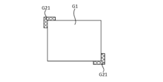
- the aerial boundary image G21 shown in FIG. 5 is provided along each of a pair of diagonally opposite corners of the four corners of the aerial image G1. Note that the aerial boundary image G21 may be provided at only one of the four corners of the aerial image G1.
- the aerial boundary image G21 may be provided at any three of the four corners of the aerial image G1. Furthermore, the aerial boundary image G21 may be provided at all four corners of the aerial image G1.
- the aerial boundary image G22 shown in FIG. 6 is arranged along only one of the four sides of the aerial image G1 (the left side in the illustrated example). Note that the aerial boundary image G22 may be arranged along any two or three of the four sides of the aerial image G1.
- the aerial boundary images G21 and G22 shown in FIG. 5 and FIG. 6 may also have an area for operation instructions. Furthermore, the aerial boundary images G21 and G22 may be three-dimensional images, similar to the aerial boundary image G2. Furthermore, the aerial boundary images G21 and G22 may be two-dimensional images.
- the aerial boundary images G1, G21, and G22 shown in Figures 4 to 6 above are boundary images for indicating the boundary between the aerial images G1, G21, and G22 and the background.
- the aerial boundary images are not limited to boundary images for indicating the boundary between the aerial image and the background.
- the aerial boundary image may be an image that is focused (in other words, formed) within the aerial image G1.
- Such an aerial boundary image is, for example, a boundary image that indicates the boundary between adjacent aerial images within the aerial image G1.
- Figures 7 and 8 show an example of an aerial boundary image that is focused (in other words, formed) within the aerial image G1.
- the aerial boundary image G23 shown in FIG. 7 has a rectangular frame shape.
- the aerial boundary image G23 is formed within the aerial image G1.
- Such an aerial boundary image G23 is formed as a three-dimensional image on the imaging plane S.
- the aerial boundary image G23 may also be formed as a two-dimensional image on the imaging plane S.
- the aerial boundary image G23 surrounds the first aerial image G1a included in the aerial image G1.
- Such an aerial boundary image G23 is an image that shows the boundary between the first aerial image G1a and the second aerial image G1b included in the aerial image G1.
- the second aerial image G1b is an image formed around the first aerial image G1a.
- the user U can recognize the boundary between the first aerial image G1a and the second aerial image G1b.
- This configuration is particularly effective when it is difficult to recognize the boundary between the first aerial image G1a and the second aerial image G1b.
- the control unit 7, which will be described later, may control the boundary image output unit 4 to form an aerial boundary image G23 when the user U has difficulty recognizing the boundary between the first aerial image G1a and the second aerial image G1b.
- control unit 7 may control the boundary image output unit 4 not to form an aerial boundary image G23 in a situation in which the boundary between the first aerial image G1a and the second aerial image G1b is easily recognized by the user U.
- the aerial boundary image G23 may be formed at a position in the aerial image G1 where the boundary between adjacent images is difficult to recognize.
- the position at which the aerial boundary image G23 is formed may be controlled by the control unit 7.
- the aerial boundary image G23 may also be formed around an aerial image that is to be emphasized and made known to the user U in the aerial image G1.
- the aerial boundary image G23 may also be formed at a position according to the procedure of the input operation of the user U.
- the aerial boundary image G24 shown in FIG. 8 is linear.
- the aerial boundary image G24 is formed within the aerial image G1.
- Such an aerial boundary image G24 is formed as a three-dimensional image on the imaging plane S.
- the aerial boundary image G24 may also be formed as a two-dimensional image on the imaging plane S.
- the aerial boundary image G24 is an image showing the boundary between a first aerial image G1c included in the aerial image G1 and a second aerial image G1d included in the aerial image G1.
- the first aerial image G1c and the second aerial image G1d are adjacent to each other in the aerial image 1G.
- the aerial boundary image G24 is also a boundary image for dividing the aerial image G1 into left and right.
- the extension direction of the aerial boundary image G24 is not limited to the left-right direction in the aerial image G1.
- the extension direction of the aerial boundary image G24 may be the up-down direction in the aerial image G1.
- the user U can recognize the boundary between the first aerial image G1c and the second aerial image G1d.
- This configuration is particularly effective when it is difficult to recognize the boundary between the first aerial image G1c and the second aerial image G1d.
- the imaging unit 5 is a plate-shaped member.
- the boundary image output unit 4 images the display image of the display unit 3 as an aerial image G1 in an aerial image area on the imaging plane S.
- the imaging unit 5 images the display boundary image of the boundary image output unit 4 as an aerial boundary image G2 in the boundary image area on the imaging plane S.
- the imaging unit 5 has a plurality of light reflecting surfaces (not shown). As shown in Fig. 1, light of a display image on the display unit 3 is incident on the imaging unit 5 from the direction indicated by the arrow A3 .
- the light of the display image incident on the imaging unit 5 may be referred to as "incident light related to the display image”.
- Incident light related to the display image is reflected multiple times (e.g., twice) by multiple light reflecting surfaces and emitted from imaging unit 5 in the direction indicated by arrow A4 in Fig. 1.
- the emitted light related to the display image is then imaged as an aerial image G1 on imaging surface S.
- the light of the display image emitted from imaging unit 5 is sometimes referred to as "emitted light related to the display image”.
- the incident angle of the incident light with respect to the display image is equal to the inclination angle ⁇ 1 with respect to the virtual line ⁇ 1 of the display unit 3.
- the incident angle of the incident light with respect to the display image is 45°.
- the exit angle of the exit light with respect to the display image is equal to the incident angle of the incident light with respect to the display image. In the present embodiment, the exit angle of the exit light with respect to the display image is 45°.
- the incident light related to the display boundary image is reflected multiple times (e.g., twice) by multiple light reflecting surfaces and emitted from the imaging unit 5 in a direction parallel to the direction indicated by the arrow A4 in Fig. 1.
- the emitted light related to the display boundary image is then imaged as an aerial boundary image G2 on the imaging surface S.
- the light of the display boundary image emitted from the imaging unit 5 is sometimes referred to as "emitted light related to the display boundary image.”
- the angle of incidence of the incident light with respect to the display boundary image is equal to the angle of incidence of the incident light with respect to the display image. In this embodiment, the angle of incidence of the incident light with respect to the display boundary image is 45°.
- the angle of emission of the emitted light with respect to the display boundary image is equal to the angle of emission of the emitted light with respect to the display image. In this embodiment, the angle of emission of the emitted light with respect to the display boundary image is 45°.
- the image forming unit that forms the aerial boundary image G2 is composed of the boundary image output unit 4, the imaging unit 5, and the control unit 7.
- the boundary image output unit 4 corresponds to an example of a light source.
- incident light related to the display image and incident light related to the display border image are incident on the imaging unit 5.
- the imaging unit 5 has an area capable of receiving both the light of the display image of the display unit 3 and the light of the display border image of the border image output unit 4.
- the input detection unit 6 (see FIG. 2) detects information (also referred to as first operation input information) regarding an operation input to the aerial image G1 from the user U (see FIG. 1).
- the input detection unit 6 sends the detected first operation input information to the control unit 7.
- the input detection unit 6 is supported by the housing 2.
- the input detection unit 6 is composed of multiple sensors (not shown).
- the input detection unit 6 detects, for example, information about the position in the aerial image G1 operated by the user U (also referred to as first position information) as first operation input information.
- the first position information may be, for example, information about coordinates in the aerial image G1 (also referred to as first coordinate information).
- the first coordinate information may be three-dimensional coordinates consisting of an X-direction coordinate, a Y-direction coordinate, and a Z-direction coordinate.
- the input detection unit 6 may also detect information (also referred to as first input depth information) regarding the input depth of the fingertip when the user U operates the aerial image G1.
- the first input depth information may include a distance D1 (see FIG. 9) that the user U's fingertip passed through the aerial image G1 when the user U operates the aerial image G1.
- the input detection unit 6 sends the detected first input depth information to the control unit 7.
- the input detection unit 6 also detects information (also referred to as second operation input information) regarding an operation input to the aerial boundary image G2 from the user U (see FIG. 1). The input detection unit 6 sends the detected information to the control unit 7.
- information also referred to as second operation input information
- first operation input information first position information, first coordinate information, and first input depth information
- first information first information
- the input detection unit 6 also detects information (also referred to as second operation input information) regarding an operation input from the user U to the aerial boundary image G2.
- the input detection unit 6 sends the detected second operation input information to the control unit 7.
- the input detection unit 6 detects, for example, information relating to the position in the aerial boundary image G2 operated by the user U (also referred to as second position information) as second operation input information.
- the second position information may be, for example, information about coordinates in the aerial boundary image G2 (also referred to as second coordinate information).
- the second coordinate information may be three-dimensional coordinates consisting of coordinates in the X direction, Y direction, and Z direction.
- the second position information may be information about the coordinates of areas R1 and R2 for operation instructions in the aerial boundary image G2.
- the input detection unit 6 may also detect information (also referred to as second input depth information) regarding the input depth of the fingertip when the user U operates the aerial boundary image G2 (specifically, the regions R1 and R2 for operation instructions).
- information also referred to as second input depth information
- the second input depth information may include a distance D2 (see FIG. 9) that the user U's fingertip passes through the aerial boundary image G2 when the user U operates the aerial boundary image G2.
- the input detection unit 6 sends the second input depth information to the control unit 7.
- second operation input information second position information, second coordinate information, and second input depth information
- second information second information
- the input detection unit (also referred to as the first input detection unit) that detects information regarding operation input to the aerial image G1 and the input detection unit (also referred to as the second input detection unit) that detects information regarding operation input to the aerial boundary image G2 are configured by a single common input detection unit.
- first input detection unit and the second input detection unit may be configured by two different input detection units.
- the function of the input detection unit 6 to detect the second operation input information, the second position information, the second coordinate information, and the second input depth information (hereinafter referred to as the function of detecting second information) may be omitted.
- the function of detecting the second information is a function that is necessary when the non-contact input device 1 has a function of executing some control based on an input operation on the aerial boundary image G2 from the user U. Therefore, the function of detecting the second information may be omitted when the non-contact input device 1 does not have a function of executing some control based on an input operation on the aerial boundary image G2 from the user U.
- the configuration of the input detection unit 6 is not particularly limited.
- the configuration of the input detection unit 6 may be various configurations that can realize the above-mentioned functions.
- the position at which the input detection unit 6 is provided is also not particularly limited.
- the input detection unit 6 may be provided in various positions that can realize the above-mentioned functions.
- the control unit 7 mainly controls the operations of the display unit 3 and the boundary image output unit 4.
- the control unit 7 is supported by the housing 2.
- the control unit 7 may be substantially configured with a CPU, ROM, RAM, HDD, etc. connected via a bus, or may be configured with a one-chip LSI, etc. The control executed by the control unit 7 will be described below.
- the control unit 7 executes display control of the aerial image. That is, the control unit 7 controls the display operation of the display unit 3. Specifically, the control unit 7 executes display control of the aerial image based on information related to an operation input by the user U of the non-contact input device 1 to the aerial image G1.
- the control unit 7 acquires information regarding the operation input of the user U of the non-contact input device 1 to the aerial image G1 from the input detection unit 6.
- the information regarding the operation input of the user U of the non-contact input device 1 to the aerial image G1 is first information detected by the input detection unit 6 (specifically, first operation input information, first position information, first coordinate information, and first input depth information).
- the control unit 7 can also control the display of the aerial image based on information regarding the user U's operation input to the aerial boundary image G2.
- the control unit 7 acquires information regarding the operation input by the user U to the aerial boundary image G2 from the input detection unit 6.
- the information regarding the operation input by the user U to the aerial boundary image G2 is second information detected by the input detection unit 6 (specifically, second operation input information, second position information, second coordinate information, and second input depth information).
- control unit 7 detects that the operation instruction area R1 in the aerial boundary image G2 has been operated based on the second information acquired from the input detection unit 6, the control unit 7 executes the function assigned to the operation instruction area R1.
- control unit 7 switches between displaying and hiding the aerial boundary image G2.
- the control unit 7 controls the boundary image output unit 4 to display the aerial boundary image G2 on the imaging surface S.
- User U can request the display of the aerial boundary image G2, for example, by performing an operation input on the aerial image G1 or the aerial boundary image G2.
- the user U can request the display of the aerial boundary image G2 by using a physical switch (not shown) provided on the non-contact input device 1.
- the control unit 7 controls the boundary image output unit 4 according to the state of the switch.
- the control unit 7 may also control the timing of displaying the aerial boundary image G2. Specifically, when the control unit 7 detects an operation from the user on the boundary image area in a state where the aerial boundary image G2 has not been formed in the boundary image area on the imaging surface S, the control unit 7 forms the aerial boundary image G2 in the boundary image area.
- the operation from the user detected by the control unit 7 may be an operation intended by the user, or an operation not intended by the user.
- the control unit 7 forms an aerial boundary image G2 to notify the user that the finger has deviated from the aerial image G1.
- the control unit 7 may also control the timing of displaying the aerial boundary image G2.
- the aerial boundary image G2 When the user U is not using the non-contact input device 1, it is preferable for the aerial boundary image G2 to be hidden from the viewpoint of energy saving. On the other hand, when the user U uses the non-contact input device 1, it is preferable for the aerial boundary image G2 to be presented to the user U in advance.
- the control unit 7 may therefore present the aerial boundary image G2 to the user U in advance at an appropriate timing before the user U starts using the non-contact input device 1.
- control unit 7 may control the boundary image output unit 4 to display the aerial boundary image G2. At this time, the control unit 7 may display the aerial image G1 together with the aerial boundary image G2.
- the non-contact input device 1 may include a user detection means (not shown) that detects when the user U enters a predetermined range around the non-contact input device 1.
- the control unit 7 controls the boundary image output unit 4 based on the information acquired from the user detection means to display the aerial boundary image G2.
- control unit 7 may control the boundary image output unit 4 to hide the aerial boundary image G2. At this time, the control unit 7 may hide the aerial image G1 together with the aerial boundary image G2.
- the control unit 7 can also execute information notification control.
- the information notification control is control for conveying information to the user U through the aerial boundary image G2.
- the control unit 7 notifies the user U of the information by controlling the operation of the boundary image output unit 4 to change the display mode of the aerial boundary image G2.
- control unit 7 executes information notification control based on information regarding the user U's operation input to the aerial image G1 (in other words, the first information acquired from the input detection unit 6).
- the control unit 7 controls the operation of the boundary image output unit 4 to change the display mode of the aerial boundary image G2.
- the user U can recognize that the operation input is incorrect from the change in the display mode of the aerial boundary image G2. As a result, the user U can perform the correct operation input to the aerial image G1.
- the control unit 7 then controls the operation of the boundary image output unit 4 in accordance with the distance D1 (see FIG. 9) that the user U's fingertip has passed through the aerial image G1, thereby changing the display mode of the aerial boundary image G2.
- control unit 7 may change the color of the aerial boundary image G2 depending on the distance D1. Specifically, when the distance D1 is within the appropriate range, the control unit 7 displays the aerial boundary image G2 in blue.
- the control unit 7 displays the aerial boundary image G2 in yellow.
- the control unit 7 displays the aerial boundary image G2 in red.
- the control unit 7 may change the display mode of the aerial boundary image G2 and notify the user U of information by audio.
- Non-contact input device 1 having the above-described configuration allows the boundaries of aerial image G1 to be clearly recognized, and also improves operability.
- the non-contact input device 1 can display an aerial boundary image G2 indicating the boundary between the aerial image G1 and the background in at least a portion of the area around the aerial image G1 (in other words, the periphery). This allows the user U of the non-contact input device 1 to clearly recognize the boundary between the aerial image G1 and the background. This effect can also be obtained from the aerial boundary image G21 shown in FIG. 5 and the aerial boundary image G22 shown in FIG. 6 described above.
- the user U of the non-contact input device 1 can clearly recognize the boundary between adjacent aerial images in the aerial image G1.
- the aerial boundary image G2 is an image formed on the imaging surface S. Therefore, when the user U operates the aerial image G1, there is no physical contact between the aerial boundary image G2 and the user U's fingers. As a result, the aerial boundary image G2 does not interfere with the operation by the user U.
- the aerial boundary image G2 is a three-dimensional image. Therefore, the user U can view the aerial boundary image G2 not only from the front, but also from the left and right directions. As a result, the user U can reliably recognize the position of the aerial image G1.
- the aerial boundary image G2 not only functions as a boundary image showing the boundary between the aerial image G1 and the background, but also functions as an input reception image that receives operational input from the user U. This improves the operability of the non-contact input device 1 for the user U.
- the non-contact input device 1 can improve the clarity of the boundary between the aerial image G1 and the background while improving the operability of the non-contact input device 1 at a high level.
- non-contact input device 1 includes boundary image output unit 4 that outputs an image that is the basis of aerial boundary image G2.
- boundary image output unit 4 may be omitted.
- display unit 3 displays a boundary image indicating the boundary between aerial image G1 and the background in a display image that is the basis of aerial image G1.
- control unit 7 controls display unit 3 to display the boundary image indicating the boundary between aerial image G1 and the background in the display image.
- the image forming unit that forms aerial boundary image G2 is composed of display unit 3, imaging unit 5, and control unit 7.
- the present invention can be applied to non-contact input devices used for a variety of purposes.
- Non-contact input device 1
- Housing 21 Support unit 3
- Boundary image output unit 5
- Imaging unit 6 Input detection unit 7
- Control unit G1 Aerial image G1a, G1c First aerial image G1b, G1d Second aerial image G2, G21, G22, G23, G24 Aerial boundary image R1, R2 Area for operation instruction U User S Imaging surface
Landscapes
- Engineering & Computer Science (AREA)
- Physics & Mathematics (AREA)
- General Engineering & Computer Science (AREA)
- Theoretical Computer Science (AREA)
- General Physics & Mathematics (AREA)
- Human Computer Interaction (AREA)
- Optics & Photonics (AREA)
- User Interface Of Digital Computer (AREA)
Abstract
Description
本発明は、非接触入力装置に関する。 The present invention relates to a non-contact input device.
従来、特許文献1に開示されたように、画像表示装置の表示部に表示された画像を空中における結像面に結像して、当該結像面に画像(以下、空中画像と称する。)を表示する非接触入力装置が知られている。
As disclosed in
ところで、上述のような特許文献1に開示された非接触入力装置は、空中画像が結像される結像面を囲むように設けられた物理的な枠を有する。このため、非接触入力装置の使用者は、空中画像と背景との境界を明確に認識できる。しかしながら、このような枠は、空中画像に対する入力操作の際に邪魔になることがあり、操作性を低下させてしまう可能性がある。
Incidentally, the non-contact input device disclosed in
又、非接触入力装置の使用者が、空中画像内で隣り合う画像同士の境界を認識しにくい場合、操作性が低下してしまう可能性がある。しかしながら、空中画像内に物理的な枠を設けることは、操作性の観点から望ましくない。 Furthermore, if a user of a non-contact input device has difficulty recognizing the boundaries between adjacent images in the aerial image, operability may be reduced. However, providing a physical frame within the aerial image is undesirable from the standpoint of operability.
本発明の目的は、空中画像の境界を明確に認識でき、且つ、操作性を向上できる非接触入力装置を提供することである。 The object of the present invention is to provide a non-contact input device that can clearly recognize the boundaries of an aerial image and improve operability.
本発明に係る非接触入力装置の一態様は、
表示部と、
前記表示部の表示画像を、空中における結像面に実像として結像する結像部と、
前記実像の周囲における少なくとも一部の領域又は実像内に、境界画像を形成する画像形成部と、を備える。
One aspect of the non-contact input device according to the present invention is
A display unit;
an imaging unit that forms a display image of the display unit as a real image on an imaging surface in the air;
and an image forming unit that forms a boundary image in at least a portion of the area around the real image or within the real image.
本発明によれば、空中画像の境界を明確に認識でき、且つ、操作性を向上できる非接触入力装置を提供できる。 The present invention provides a non-contact input device that can clearly recognize the boundaries of an aerial image and improves operability.
以下、本発明に係る非接触入力装置について、図面に基づいて詳細に説明する。尚、以下で説明する非接触入力装置は、本発明に係る非接触入力装置の一例であり、本発明は後述の実施形態により限定されない。 The non-contact input device according to the present invention will be described in detail below with reference to the drawings. Note that the non-contact input device described below is one example of the non-contact input device according to the present invention, and the present invention is not limited to the embodiment described below.
[実施形態]
図1~図10を参照して、本発明の実施形態に係る非接触入力装置1について説明する。
[Embodiment]
A
図1は、本実施形態に係る非接触入力装置1の構成を示す模式断面図である。非接触入力装置1は、所謂空中ディスプレイを備えた装置である。空中ディスプレイは、空中に情報や映像を投影することができる。
FIG. 1 is a schematic cross-sectional view showing the configuration of a
このような非接触入力装置1は、種々の場所(店舗、公共施設、医療現場、及び工場等)において、ユーザUが情報を入力するための端末、又は、ユーザUが情報を取得するための端末として使用される。
Such a
具体的には、非接触入力装置1は、会計端末又は受付端末として使用されてよい。又、非接触入力装置1は、種々の装置への操作入力を入力するための操作入力端末として使用されてもよい。
Specifically, the
以下の説明において、非接触入力装置1及び非接触入力装置1を構成する各部材の構造を説明するにあたり、図1に示す直交座標系(X、Y、Z)を使用することもある。X方向は、非接触入力装置1の前後方向に一致する。X方向+側は、非接触入力装置1の前側に一致する。X方向-側は、非接触入力装置1の後側に一致する。
In the following explanation, when describing the structure of the
又、Y方向は、非接触入力装置1の左右方向及び非接触入力装置1の幅方向に一致する。Y方向+側は、非接触入力装置1の前方から非接触入力装置1を見た場合の左側に一致する。Y方向-側は、非接触入力装置1の前方から非接触入力装置1を見た場合の右側に一致する。
The Y direction corresponds to the left-right direction and width direction of the
Z方向は、非接触入力装置1の上下方向に一致する。Z方向+側は、非接触入力装置1の上側に一致する。Z方向-側は、非接触入力装置1の下側に一致する。
The Z direction corresponds to the up-down direction of the
(非接触入力装置)
非接触入力装置1は、筐体2、表示部3、境界画像出力部4、結像部5、入力検出部6、及び制御部7を有する。
(Non-contact input device)
The
本実施形態に係る非接触入力装置1は、所謂縦置き式の非接触入力装置である。縦置き式の非接触入力装置の場合、境界画像G1は、図1に示すように、非接触入力装置1の前方に表示される。尚、非接触入力装置は、縦置き式の非接触入力装置に限定されない。
The
非接触入力装置は、所謂横置き式の非接触入力装置であってもよい。横置き式の非接触入力装置は、図1に示す非接触入力装置1を図1における時計回りの方向と反対方向に90°回転させた如き構成を有する。横置き式の非接触入力装置の場合、境界画像G1は、非接触入力装置1の上方に表示される。
The non-contact input device may be a so-called horizontally placed non-contact input device. A horizontally placed non-contact input device has a configuration in which the
(筐体)
筐体2は、箱状であって、非接触入力装置1を構成する各エレメント2~7を収容又は支持するための部材である。本実施形態の場合、筐体2は、上下方向に長い直方体状である。但し、筐体の形状は、本実施形態の筐体2の形状に限定されない。筐体の形状は、非接触入力装置1が設置される環境に応じて適宜決定されてよい。
(Housing)
The
(表示部)
表示部3は、例えば、画像を表示する種々のディスプレイ(例えば、液晶ディスプレイ)であってよい。表示部3は、支持部21を介して、筐体2に支持されている。表示部3は、後述の結像部5に向かって、前側斜め下方を向いている。
(Display)
The
具体的には、表示部3は、鉛直方向に平行な仮想線α1に対して、表示部3の上端が後述の結像部5に近づく方向に所定角度θ1傾いた状態で、支持部21に支持されている。本実施形態の場合、所定角度θ1は、45°である。
Specifically, the
表示部3が表示する表示画像は、後述の結像部5により、結像面Sに空中画像G1として結像される。空中画像G1は、実像の一例に該当する。結像面Sは、筐体2の外部の空中に存在する仮想領域である。結像面Sは、後述の空中画像G1及び空中境界画像G2を結像可能な大きさを有する仮想領域と捉えてよい。尚、結像面Sにおいて、空中画像G1が結像される領域を、空中画像領域と称することもある。又、結像面Sにおいて、空中境界画像G2が結像される領域を、境界画像領域と称することもある。
The display image displayed by the
又、結像面Sは、後述の結像部5(換言すれば、仮想線α2)に関して、表示部3と面対称となる位置に存在する仮想領域である。仮想線α2は、結像部5を通り、鉛直方向に平行な仮想線である。
The imaging surface S is a virtual area that exists at a position that is plane-symmetrical to the
具体的には、結像面Sは、鉛直方向に平行な仮想線α3に対して、結像面Sの上端が後述の結像部5に近づく方向に所定角度θ2傾いた仮想領域である。本実施形態の場合、所定角度θ2は、45°である。
Specifically, the imaging surface S is a virtual area inclined at a predetermined angle θ2 with respect to a virtual line α3 parallel to the vertical direction such that the upper end of the imaging surface S approaches an
表示部3の表示動作は、後述の制御部7により制御される。制御部7による表示部3の制御処理については、後述する。
The display operation of the
(境界画像出力部)
境界画像出力部4は、表示境界画像を表示する種々のディスプレイ又は表示境界画像を出力するレーザ装置であってよい。表示部3は、支持部21を介して、筐体2に支持されている。
(Boundary image output unit)
The boundary
境界画像出力部4は、図3に示すように、矩形枠状であって、表示部3の外縁部を全周にわたり囲んでいる。図3は、表示部3及び境界画像出力部4を、図1の矢印A1が示す方向から見た図である。図1の矢印A1は、表示部3及び境界画像出力部4の表示面の法線方向に平行である。
As shown in Fig. 3, the boundary
境界画像出力部4は、表示部3と同じ方向を向いている。つまり、境界画像出力部4は、結像部5に向かって、前側斜め下方を向いている。
The border
具体的には、境界画像出力部4は、表示部3と同様に、鉛直方向に平行な仮想線α1に対して、境界画像出力部4の上端が後述の結像部5に近づく方向に所定角度θ1傾いた状態で、支持部21に支持されている。本実施形態の場合、所定角度θ1は、45°である。尚、境界画像出力部4は、表示部3を介して、筐体2に支持されてもよい。
Specifically, the boundary
境界画像出力部4が出力する表示境界画像は、後述の結像部5により、結像面Sに空中境界画像G2として結像される。空中境界画像G2は、境界画像の一例に該当する。
The display boundary image output by the boundary
図4は、境界画像出力部4の形状が図3に示す矩形枠状の場合に、結像面Sに結像される空中境界画像G2の一例を示している。図4は、空中境界画像G2を図1の矢印A2が示す方向から見た図である。図1の矢印A2は、空中境界画像G2(換言すれば、結像面S)の法線方向に平行である。図4において斜格子が付された部分が、空中境界画像G2である。
Fig. 4 shows an example of an aerial boundary image G2 formed on the imaging plane S when the shape of the boundary
空中境界画像G2は、矩形枠状であって、空中画像G1の外周縁を全周にわたり囲むように、結像面Sに結像される。 The aerial boundary image G2 has a rectangular frame shape and is imaged on the imaging surface S so as to completely surround the outer edge of the aerial image G1.
又、本実施形態の場合、空中境界画像G2は、図1及び図10に示すように、結像面Sに三次元画像として結像されている。つまり、空中境界画像G2は、厚みを有する。空中境界画像G2が三次元画像である場合、非接触入力装置1のユーザUは、前方からだけでなく、左右方向からも空中境界画像G2を視認できる。この結果、ユーザUは、空中画像G1の位置を、確実に認識できる。
In addition, in this embodiment, the aerial boundary image G2 is formed as a three-dimensional image on the imaging surface S, as shown in Figures 1 and 10. In other words, the aerial boundary image G2 has thickness. When the aerial boundary image G2 is a three-dimensional image, the user U of the
このような構成は、本実施形態に係る非接触入力装置1のような縦置き式の非接触入力装置に対して、特に有効である。尚、空中境界画像は、結像面Sに結像された二次元画像であってもよい。
This configuration is particularly effective for a vertically-mounted non-contact input device such as the
空中境界画像G2は、複数の操作指示用の領域R1、R2を有してよい。操作指示用の領域R1、R2は、非接触入力装置1のユーザU(図1参照)が、操作入力を入力するための領域である。操作指示用の領域R1、R2のそれぞれに、機能が割り振られている。
The aerial boundary image G2 may have a plurality of regions R1, R2 for operation instructions. The regions R1, R2 for operation instructions are regions for a user U (see FIG. 1) of the
例えば、操作指示用の領域R1には、表示部3の表示態様を切り換えるための第一機能(例えば、表示部3の表示画像を拡大する機能)が割り当てられてよい。この場合、ユーザUが、操作指示用の領域R1に対して所定の操作を行うと、第一機能が実現される。 For example, a first function for switching the display mode of the display unit 3 (for example, a function for enlarging the display image of the display unit 3) may be assigned to the operation instruction area R1. In this case, when the user U performs a predetermined operation on the operation instruction area R1, the first function is realized.
又、操作指示用の領域R2には、表示部3の表示態様を切り換えるための第二機能(例えば、表示部3の表示画像を縮小する機能)が割り当てられてよい。この場合、ユーザUが、操作指示用の領域R2に対して所定の操作を行うと、第二機能が実現される。 Furthermore, a second function for switching the display mode of the display unit 3 (for example, a function for reducing the display image of the display unit 3) may be assigned to the operation instruction area R2. In this case, when the user U performs a predetermined operation on the operation instruction area R2, the second function is realized.
このように本実施形態の場合、空中境界画像G2は、空中画像G1と背景との境界を示す境界画像としての機能だけでなく、ユーザUからの操作入力を受け付ける入力受付画像としての機能も有する。 In this embodiment, the aerial boundary image G2 not only functions as a boundary image showing the boundary between the aerial image G1 and the background, but also functions as an input reception image that receives operational input from the user U.
尚、操作指示用の領域の数及び配置は、図3に示された操作指示用の領域R1、R2の数及び配置に限定されない。 The number and arrangement of regions for operation instructions are not limited to the number and arrangement of regions R1 and R2 for operation instructions shown in FIG. 3.
又、空中境界画像の形状は、図3に示された空中境界画像G2の形状に限定されない。図5及び図6は、空中境界画像の変形例1及び変形例2を示す図である。 Furthermore, the shape of the aerial boundary image is not limited to the shape of the aerial boundary image G2 shown in FIG. 3. FIG. 5 and FIG. 6 are diagrams showing modified example 1 and modified example 2 of the aerial boundary image.
図5に示す空中境界画像G21は、空中画像G1の4つの隅部のうち、対角上に位置する1対の隅部のそれぞれに沿うように設けられている。尚、空中境界画像G21は、空中画像G1の4つの隅部のうちの1つの隅部にのみ設けられてもよい。 The aerial boundary image G21 shown in FIG. 5 is provided along each of a pair of diagonally opposite corners of the four corners of the aerial image G1. Note that the aerial boundary image G21 may be provided at only one of the four corners of the aerial image G1.
又、空中境界画像G21は、空中画像G1の4つの隅部のうちの任意の3つの隅部に設けられてもよい。更に、空中境界画像G21は、空中画像G1の4つの隅部の総てに設けられてもよい。 Also, the aerial boundary image G21 may be provided at any three of the four corners of the aerial image G1. Furthermore, the aerial boundary image G21 may be provided at all four corners of the aerial image G1.
図6に示す空中境界画像G22は、空中画像G1の4辺のうちの1辺(図示の場合、左辺)のみに沿うように設けられている。尚、空中境界画像G22は、空中画像G1の4辺のうちの任意の2辺又は3辺のみに設けられてもよい。 The aerial boundary image G22 shown in FIG. 6 is arranged along only one of the four sides of the aerial image G1 (the left side in the illustrated example). Note that the aerial boundary image G22 may be arranged along any two or three of the four sides of the aerial image G1.
図5及び図6に示す空中境界画像G21、G22も、操作指示用の領域を有してよい。又、空中境界画像G21、G22は、空中境界画像G2と同様に、三次元画像であってもよい。尚、空中境界画像G21、G22は、二次元画像であってもよい。 The aerial boundary images G21 and G22 shown in FIG. 5 and FIG. 6 may also have an area for operation instructions. Furthermore, the aerial boundary images G21 and G22 may be three-dimensional images, similar to the aerial boundary image G2. Furthermore, the aerial boundary images G21 and G22 may be two-dimensional images.
上述の図4~図6に示す空中境界画像G1、G21、G22は、空中画像G1、G21、G22と背景との境界を示すための境界画像である。但し、空中境界画像は、空中画像と背景との境界を示すための境界画像に限定されない。 The aerial boundary images G1, G21, and G22 shown in Figures 4 to 6 above are boundary images for indicating the boundary between the aerial images G1, G21, and G22 and the background. However, the aerial boundary images are not limited to boundary images for indicating the boundary between the aerial image and the background.
具体的には、空中境界画像は、空中画像G1内に結像される(換言すれば、形成される)画像であってもよい。このような空中境界画像は、例えば、空中画像G1内で隣り合う空中画像同士の境界を示すための境界画像である。 Specifically, the aerial boundary image may be an image that is focused (in other words, formed) within the aerial image G1. Such an aerial boundary image is, for example, a boundary image that indicates the boundary between adjacent aerial images within the aerial image G1.
図7及び図8は、空中画像G1内に結像される(換言すれば、形成される)空中境界画像の一例を示す図である。 Figures 7 and 8 show an example of an aerial boundary image that is focused (in other words, formed) within the aerial image G1.
図7に示す空中境界画像G23は、矩形枠状である。空中境界画像G23は、空中画像G1内に結像される。このような空中境界画像G23は、結像面Sに三次元画像として結像されている。尚、空中境界画像G23は、結像面Sに二次元画像として結像されてもよい。 The aerial boundary image G23 shown in FIG. 7 has a rectangular frame shape. The aerial boundary image G23 is formed within the aerial image G1. Such an aerial boundary image G23 is formed as a three-dimensional image on the imaging plane S. Note that the aerial boundary image G23 may also be formed as a two-dimensional image on the imaging plane S.
空中境界画像G23は、空中画像G1に含まれる第一空中画像G1aを囲んでいる。このような空中境界画像G23は、第一空中画像G1aと、空中画像G1に含まれる第二空中画像G1bとの境界を示す画像である。第二空中画像G1bは、第一空中画像G1aの周囲に結像されている画像である。 The aerial boundary image G23 surrounds the first aerial image G1a included in the aerial image G1. Such an aerial boundary image G23 is an image that shows the boundary between the first aerial image G1a and the second aerial image G1b included in the aerial image G1. The second aerial image G1b is an image formed around the first aerial image G1a.
このような構成によれば、ユーザUは、第一空中画像G1aと第二空中画像G1bとの境界を認識できる。特に、このような構成は、第一空中画像G1aと第二空中画像G1bとの境界を認識しにくい場合に、有効である。 With this configuration, the user U can recognize the boundary between the first aerial image G1a and the second aerial image G1b. This configuration is particularly effective when it is difficult to recognize the boundary between the first aerial image G1a and the second aerial image G1b.
後述の制御部7は、第一空中画像G1aと第二空中画像G1bとの境界がユーザUに認識されにくい状況の場合に、空中境界画像G23を結像するように、境界画像出力部4を制御してもよい。
The
換言すれば、制御部7は、第一空中画像G1aと第二空中画像G1bとの境界がユーザUに認識されやすい状況の場合に、空中境界画像G23を結像しないように、境界画像出力部4を制御してもよい。
In other words, the
つまり、空中境界画像G23は、空中画像G1において、隣り合う画像同士の境界が認識しにくい位置に、結像されてよい。空中境界画像G23が結像される位置は、制御部7により制御されてよい。
In other words, the aerial boundary image G23 may be formed at a position in the aerial image G1 where the boundary between adjacent images is difficult to recognize. The position at which the aerial boundary image G23 is formed may be controlled by the
又、空中境界画像G23は、空中画像G1において、ユーザUに強調して知らせたい空中画像の周囲に結像されてもよい。又、空中境界画像G23は、ユーザUの入力操作の手順に応じた位置に結像されてもよい。 The aerial boundary image G23 may also be formed around an aerial image that is to be emphasized and made known to the user U in the aerial image G1. The aerial boundary image G23 may also be formed at a position according to the procedure of the input operation of the user U.
又、図8に示す空中境界画像G24は、直線状である。空中境界画像G24は、空中画像G1内に結像される。このような空中境界画像G24は、結像面Sに三次元画像として結像されている。尚、空中境界画像G24は、結像面Sに二次元画像として結像されてもよい。 The aerial boundary image G24 shown in FIG. 8 is linear. The aerial boundary image G24 is formed within the aerial image G1. Such an aerial boundary image G24 is formed as a three-dimensional image on the imaging plane S. The aerial boundary image G24 may also be formed as a two-dimensional image on the imaging plane S.
空中境界画像G24は、空中画像G1に含まれる第一空中画像G1cと、空中画像G1に含まれる第二空中画像G1dとの境界を示す画像である。第一空中画像G1cと第二空中画像G1dとは、空中画像1Gにおいて隣り合っている。 The aerial boundary image G24 is an image showing the boundary between a first aerial image G1c included in the aerial image G1 and a second aerial image G1d included in the aerial image G1. The first aerial image G1c and the second aerial image G1d are adjacent to each other in the aerial image 1G.
空中境界画像G24は、空中画像G1を左右に分割するための境界画像でもある。尚、空中境界画像G24の延在方向は、空中画像G1における左右方向に限定されない。空中境界画像G24の延在方向は、空中画像G1における上下方向であってもよい。 The aerial boundary image G24 is also a boundary image for dividing the aerial image G1 into left and right. The extension direction of the aerial boundary image G24 is not limited to the left-right direction in the aerial image G1. The extension direction of the aerial boundary image G24 may be the up-down direction in the aerial image G1.
このような構成によれば、ユーザUは、第一空中画像G1cと第二空中画像G1dとの境界を認識できる。特に、このような構成は、第一空中画像G1cと第二空中画像G1dとの境界を認識しにくい場合に、有効である。 With this configuration, the user U can recognize the boundary between the first aerial image G1c and the second aerial image G1d. This configuration is particularly effective when it is difficult to recognize the boundary between the first aerial image G1c and the second aerial image G1d.
(結像部)
結像部5は、図1に示すように、プレート状の部材である。境界画像出力部4は、表示部3の表示画像を、結像面Sにおける空中画像領域に空中画像G1として結像する。又、結像部5は、境界画像出力部4の表示境界画像を、結像面Sにおける境界画像領域に空中境界画像G2として結像する。
(Imaging section)
As shown in Fig. 1, the
本実施形態の場合、結像部5は、複数の光反射面(不図示)を有する。図1に示すように、結像部5には、矢印A3が示す方向から、表示部3における表示画像の光が入射する。以下、結像部5に入射する表示画像の光を、「表示画像に関する入射光」と称することもある。
In this embodiment, the
表示画像に関する入射光は、複数の光反射面により、複数回(例えば、2回)反射して、結像部5から図1の矢印A4が示す方向に出射される。そして、表示画像に関する出射光は、結像面Sに空中画像G1として結像される。結像部5から出射された表示画像の光を、「表示画像に関する出射光」と称することもある。
Incident light related to the display image is reflected multiple times (e.g., twice) by multiple light reflecting surfaces and emitted from
尚、表示画像に関する入射光の入射角は、表示部3の仮想線α1に対する傾斜角度θ1と等しい。本実施形態の場合、表示画像に関する入射光の入射角は、45°である。又、表示画像に関する出射光の出射角は、表示画像に関する入射光の入射角と等しい。本実施形態の場合、表示画像に関する出射光の出射角は、45°である。
The incident angle of the incident light with respect to the display image is equal to the inclination angle θ1 with respect to the virtual line α1 of the
又、図1に示すように、結像部5には、矢印A3が示す方向と平行な方向から、境界画像出力部4における表示境界画像の光も入射する。以下、結像部5に入射する表示境界画像の光を、「表示境界画像に関する入射光」と称することもある。
1, light of the display boundary image in the boundary
表示境界画像に関する入射光は、複数の光反射面により、複数回(例えば、2回)反射して、結像部5から図1の矢印A4が示す方向と平行な方向に出射される。そして、表示境界画像に関する出射光は、結像面Sに空中境界画像G2として結像される。結像部5から出射された表示境界画像の光を、「表示境界画像に関する出射光」と称することもある。
The incident light related to the display boundary image is reflected multiple times (e.g., twice) by multiple light reflecting surfaces and emitted from the
尚、表示境界画像に関する入射光の入射角は、表示画像に関する入射光の入射角と等しい。本実施形態の場合、表示境界画像に関する入射光の入射角は、45°である。又、表示境界画像に関する出射光の出射角は、表示画像に関する出射光の出射角と等しい。本実施形態の場合、表示境界画像に関する出射光の出射角は、45°である。 The angle of incidence of the incident light with respect to the display boundary image is equal to the angle of incidence of the incident light with respect to the display image. In this embodiment, the angle of incidence of the incident light with respect to the display boundary image is 45°. In addition, the angle of emission of the emitted light with respect to the display boundary image is equal to the angle of emission of the emitted light with respect to the display image. In this embodiment, the angle of emission of the emitted light with respect to the display boundary image is 45°.
以上のように、本実施形態の場合、空中境界画像G2を形成する画像形成部は、境界画像出力部4、結像部5、及び制御部7により構成されている。境界画像出力部4は、光源の一例に該当する。
As described above, in this embodiment, the image forming unit that forms the aerial boundary image G2 is composed of the boundary
又、結像部5には、表示画像に関する入射光及び表示境界画像に関する入射光が入射する。つまり、結像部5は、表示部3の表示画像の光と境界画像出力部4の表示境界画像の光との双方を受光可能な面積を有している。
In addition, incident light related to the display image and incident light related to the display border image are incident on the
(入力検出部)
入力検出部6(図2参照)は、ユーザU(図1参照)からの、空中画像G1に対する操作入力に関する情報(第一操作入力情報とも称する。)を検出する。入力検出部6は、検出した第一操作入力情報を、制御部7に送る。このような入力検出部6は、筐体2に支持されている。
(Input detection section)
The input detection unit 6 (see FIG. 2) detects information (also referred to as first operation input information) regarding an operation input to the aerial image G1 from the user U (see FIG. 1). The
入力検出部6は、複数のセンサ(不図示)により構成されている。入力検出部6は、例えば、ユーザUが操作した空中画像G1における位置に関する情報(第一位置情報とも称する。)を、第一操作入力情報として検出する。
The
第一位置情報は、例えば、空中画像G1における座標に関する情報(第一座標情報とも称する。)であってよい。第一座標情報は、X方向の座標、Y方向の座標、及びZ方向の座標からなる三次元座標であってよい。 The first position information may be, for example, information about coordinates in the aerial image G1 (also referred to as first coordinate information). The first coordinate information may be three-dimensional coordinates consisting of an X-direction coordinate, a Y-direction coordinate, and a Z-direction coordinate.
又、入力検出部6は、ユーザUが空中画像G1を操作した際の、指先の入力深さに関する情報(第一入力深さ情報とも称する。)を検出してもよい。第一入力深さ情報は、ユーザUが空中画像G1を操作した際に、ユーザUの指先が空中画像G1を通過した距離D1(図9参照)を含んでよい。入力検出部6は、検出した第一入力深さ情報を、制御部7に送る。
The
又、入力検出部6は、ユーザU(図1参照)からの、空中境界画像G2に対する操作入力に関する情報(第二操作入力情報とも称する。)を検出する。入力検出部6は、検出した情報を、制御部7に送る。
The
上述の第一操作入力情報、第一位置情報、第一座標情報、及び第一入力深さ情報を、まとめて第一情報と称することもある。 The above-mentioned first operation input information, first position information, first coordinate information, and first input depth information may be collectively referred to as first information.
又、入力検出部6は、ユーザUからの、空中境界画像G2に対する操作入力に関する情報(第二操作入力情報とも称する。)を検出する。入力検出部6は、検出した第二操作入力情報を、制御部7に送る。
The
入力検出部6は、例えば、ユーザUが操作した空中境界画像G2における位置に関する情報(第二位置情報とも称する。)を、第二操作入力情報として検出する。
The
第二位置情報は、例えば、空中境界画像G2における座標に関する情報(第二座標情報とも称する。)であってよい。第二座標情報は、X方向の座標、Y方向の座標、及びZ方向の座標からなる三次元座標であってよい。具体的には、第二位置情報は、空中境界画像G2における操作指示用の領域R1、R2の座標に関する情報であってよい。 The second position information may be, for example, information about coordinates in the aerial boundary image G2 (also referred to as second coordinate information). The second coordinate information may be three-dimensional coordinates consisting of coordinates in the X direction, Y direction, and Z direction. Specifically, the second position information may be information about the coordinates of areas R1 and R2 for operation instructions in the aerial boundary image G2.
又、入力検出部6は、ユーザUが空中境界画像G2(具体的には、操作指示用の領域R1、R2)を操作した際の、指先の入力深さに関する情報(第二入力深さ情報とも称する。)を検出してもよい。
The
第二入力深さ情報は、ユーザUが空中境界画像G2を操作した際に、ユーザUの指先が空中境界画像G2を通過した距離D2(図9参照)を含んでよい。入力検出部6は、第二入力深さ情報を、制御部7に送る。
The second input depth information may include a distance D2 (see FIG. 9) that the user U's fingertip passes through the aerial boundary image G2 when the user U operates the aerial boundary image G2. The
上述の第二操作入力情報、第二位置情報、第二座標情報、及び第二入力深さ情報を、まとめて第二情報と称することもある。 The above-mentioned second operation input information, second position information, second coordinate information, and second input depth information may be collectively referred to as second information.
尚、本実施形態の場合、空中画像G1に対する操作入力に関する情報を検出する入力検出部(第一入力検出部とも称する。)と、空中境界画像G2に対する操作入力に関する情報を検出する入力検出部(第二入力検出部とも称する。)とは、共通した一つの入力検出部により構成されている。 In this embodiment, the input detection unit (also referred to as the first input detection unit) that detects information regarding operation input to the aerial image G1 and the input detection unit (also referred to as the second input detection unit) that detects information regarding operation input to the aerial boundary image G2 are configured by a single common input detection unit.
但し、第一入力検出部と第二入力検出部とは、異なる二つの入力検出部により構成されてもよい。 However, the first input detection unit and the second input detection unit may be configured by two different input detection units.
又、入力検出部6が第二操作入力情報、第二位置情報、第二座標情報、及び第二入力深さ情報を検出する機能(以下、第二情報を検出する機能と称する。)は、省略されてもよい。
Furthermore, the function of the
第二情報を検出する機能は、非接触入力装置1がユーザUからの空中境界画像G2に対する入力操作に基づいて、何らかの制御を実行する機能を有する場合に、必要となる機能である。よって、第二情報を検出する機能は、非接触入力装置1がユーザUからの空中境界画像G2に対する入力操作に基づいて、何らかの制御を実行する機能を有していない場合には、省略されてよい。
The function of detecting the second information is a function that is necessary when the
又、入力検出部6の構成は、特に限定されない。入力検出部6の構成は、上述の機能を実現できる種々の構成であってよい。又、入力検出部6が設けられる位置も、特に限定されない。入力検出部6は、上述の機能を実現できる種々の位置に設けられてよい。
Furthermore, the configuration of the
(制御部)
制御部7は、主に、表示部3及び境界画像出力部4の動作を制御する。制御部7は、筐体2に支持されている。制御部7は、実体的には、CPU、ROM、RAM、及びHDD等がバスで接続される構成、又は、ワンチップのLSI等からなる構成であってよい。以下、制御部7が実行する制御について説明する。
(Control Unit)
The
(空中画像の表示制御)
制御部7は、空中画像の表示制御を実行する。つまり、制御部7は、表示部3の表示動作を制御する。具体的には、制御部7は、非接触入力装置1のユーザUの空中画像G1に対する操作入力に関する情報に基づいて、空中画像の表示制御を実行する。
(Display control of aerial images)
The
制御部7は、非接触入力装置1のユーザUの空中画像G1に対する操作入力に関する情報を、入力検出部6から取得する。非接触入力装置1のユーザUの空中画像G1に対する操作入力に関する情報は、入力検出部6により検出される第一情報(具体的には、第一操作入力情報、第一位置情報、第一座標情報、及び第一入力深さ情報)である。
The
制御部7は、ユーザUの空中境界画像G2に対する操作入力に関する情報に基づいて、空中画像の表示制御を実行することもできる。
The
制御部7は、ユーザUの空中境界画像G2に対する操作入力に関する情報を、入力検出部6から取得する。ユーザUの空中境界画像G2に対する操作入力に関する情報は、入力検出部6により検出される第二情報(具体的には、第二操作入力情報、第二位置情報、第二座標情報、及び第二入力深さ情報)である。
The
具体的には、制御部7は、入力検出部6から取得した第二情報に基づいて空中境界画像G2における操作指示用の領域R1が操作されたことを検出した場合、操作指示用の領域R1に割り当てられた機能を実行する。
Specifically, when the
又、制御部7は、入力検出部6から取得した第二情報に基づいて空中境界画像G2における操作指示用の領域R2が操作されたことを検出した場合、操作指示用の領域R2に割り当てられた機能を実行する。
In addition, when the
(境界画像表示制御)
又、制御部7は、境界画像表示制御を実行する。つまり、制御部7は、境界画像出力部4の表示動作を制御する。具体的には、制御部7は、非接触入力装置1のユーザUからの操作入力に基づいて、境界画像出力部4の表示動作を制御する。
(Border image display control)
In addition, the
制御部7は、境界画像表示制御において、例えば、空中境界画像G2の表示/非表示を切り換える。
In controlling the boundary image display, the
制御部7は、ユーザUから空中境界画像G2の表示要求(境界画像表示要求とも称する。)が入力された場合、境界画像出力部4を制御して、結像面Sに空中境界画像G2を表示する。
When a display request for the aerial boundary image G2 (also referred to as a boundary image display request) is input from the user U, the
ユーザUは、空中境界画像G2の表示要求を、例えば、空中画像G1又は空中境界画像G2に対する操作入力により行うことができる。 User U can request the display of the aerial boundary image G2, for example, by performing an operation input on the aerial image G1 or the aerial boundary image G2.
又、ユーザUは、空中境界画像G2の表示要求を、非接触入力装置1に設けられた物理的なスイッチ(不図示)により行うこともできる。この場合、制御部7は、スイッチの状態に応じて、境界画像出力部4を制御する。
Alternatively, the user U can request the display of the aerial boundary image G2 by using a physical switch (not shown) provided on the
又、制御部7は、空中境界画像G2を表示するタイミングを制御してもよい。具体的には、制御部7は、結像面Sにおける境界画像領域に空中境界画像G2が形成されていない状態で、境界画像領域に対するユーザからの操作を検出した場合に、境界画像領域に空中境界画像G2を形成する。
The
尚、このような制御において制御部7が検出するユーザからの操作は、ユーザが意図した操作であってもよいし、意図しない操作であってもよい。例えば、ユーザの指が空中画像G1から逸脱して境界画像領域に浸入した場合に、制御部7は、空中境界画像G2を形成することにより、ユーザに、指が空中画像G1から逸脱したことを通知する。
In addition, in such control, the operation from the user detected by the
又、制御部7は、空中境界画像G2を表示するタイミングを制御してもよい。ユーザUが非接触入力装置1を使用していない状態では、省エネの観点から、空中境界画像G2が非表示であると好ましい。一方、ユーザUが非接触入力装置1を使用する場合、事前にユーザUに対して空中境界画像G2を提示しておくことが好ましい。
The
そこで、制御部7は、ユーザUが非接触入力装置1の使用を開始する前の適宜のタイミングで、ユーザUに対して予め空中境界画像G2を提示してもよい。
The
具体的には、制御部7は、ユーザUが非接触入力装置1の周囲における所定範囲に入った場合に、境界画像出力部4を制御して、空中境界画像G2を表示してもよい。この際、制御部7は、空中境界画像G2とともに、空中画像G1を表示してもよい。
Specifically, when the user U enters a predetermined range around the
この場合、非接触入力装置1は、ユーザUが非接触入力装置1の周囲における所定範囲に入ったことを検出するユーザ検出手段(不図示)を備えてよい。制御部7は、ユーザ検出手段から取得した情報に基づいて、境界画像出力部4を制御して、空中境界画像G2を表示する。
In this case, the
又、制御部7は、ユーザUが非接触入力装置1の周囲における所定範囲から出た場合に、境界画像出力部4を制御して、空中境界画像G2を非表示にしてもよい。この際、制御部7は、空中境界画像G2とともに、空中画像G1を非表示にしてもよい。
In addition, when the user U leaves a predetermined range around the
(情報通知制御)
又、制御部7は、情報通知制御を実行することもできる。情報通知制御は、空中境界画像G2によりユーザUに情報を伝えるための制御である。制御部7は、境界画像出力部4の動作を制御して空中境界画像G2の表示態様を変えることにより、ユーザUに情報を通知する。
(Information notification control)
The
例えば、制御部7は、ユーザUの空中画像G1に対する操作入力に関する情報(換言すれば、入力検出部6から取得した第一情報)に基づいて、情報通知制御を実行する。
For example, the
具体的には、制御部7は、ユーザUの空中画像G1に対する操作入力が正しくない場合、境界画像出力部4の動作を制御して、空中境界画像G2の表示態様を変える。ユーザUは、空中境界画像G2の表示態様の変化により、操作入力が正しくないことを認識できる。その結果、ユーザUは、空中画像G1に対して正しい操作入力を行うことができる。
Specifically, if the user U's operation input to the aerial image G1 is incorrect, the
例えば、ユーザUが空中画像G1を操作する際、ユーザUの指先が空中画像G1に対して深く入り込み過ぎると、ユーザUが意図しない操作入力が入力されてしまう可能性がある。 For example, when user U operates aerial image G1, if user U's fingertips penetrate too deeply into aerial image G1, there is a possibility that an operation input unintended by user U may be input.
そこで、制御部7は、ユーザUの指先が空中画像G1を通過した距離D1(図9参照)に応じて、境界画像出力部4の動作を制御して、空中境界画像G2の表示態様を変える。
The
例えば、制御部7は、距離D1に応じて、空中境界画像G2の色を変えてよい。具体的には、制御部7は、距離D1が適正範囲に含まれる場合、空中境界画像G2を青色で表示する。
For example, the
又、制御部7は、距離D1が適正範囲より大きく第一閾値以下の場合、空中境界画像G2を黄色で表示する。制御部7は、距離D1が第一閾値より大きく第二閾値以下の場合、空中境界画像G2を赤色で表示する。
Furthermore, when the distance D1 is greater than the appropriate range and equal to or less than the first threshold, the
尚、制御部7は、空中境界画像G2の表示態様を変えるとともに、音声によりユーザUに情報を通知してもよい。
The
(本実施形態の作用・効果)
以上のような構成を備える非接触入力装置1によれば、空中画像G1の境界を明確に認識でき、且つ、操作性を向上できる。
(Actions and Effects of the Present Embodiment)
先ず、非接触入力装置1は、空中画像G1の周囲における少なくとも一部の領域(換言すれば、周辺)に、空中画像G1と背景との境界を示す空中境界画像G2を表示することができる。このため、非接触入力装置1のユーザUは、空中画像G1と背景との境界をはっきり認識できる。このような効果は、上述の図5に示す空中境界画像G21、及び、図6に示す空中境界画像G22からも得ることができる。
First, the
又、上述の図7に示す空中境界画像G23、及び、図8に示す空中境界画像G24の場合、非接触入力装置1のユーザUは、空中画像G1において隣り合う空中画像同士の境界をはっきり認識できる。
Furthermore, in the case of the aerial boundary image G23 shown in FIG. 7 and the aerial boundary image G24 shown in FIG. 8 described above, the user U of the
又、空中境界画像G2は、結像面Sに結像された画像である。よって、ユーザUが空中画像G1を操作する際、空中境界画像G2とユーザUの指とが物理的に接触することがない。この結果、空中境界画像G2がユーザUによる操作の邪魔になることはない。 Furthermore, the aerial boundary image G2 is an image formed on the imaging surface S. Therefore, when the user U operates the aerial image G1, there is no physical contact between the aerial boundary image G2 and the user U's fingers. As a result, the aerial boundary image G2 does not interfere with the operation by the user U.
又、空中境界画像G2は、三次元画像である。このため、ユーザUは、前方からだけでなく、左右方向からも空中境界画像G2を視認できる。この結果、ユーザUは、空中画像G1の位置を、確実に認識できる。 Furthermore, the aerial boundary image G2 is a three-dimensional image. Therefore, the user U can view the aerial boundary image G2 not only from the front, but also from the left and right directions. As a result, the user U can reliably recognize the position of the aerial image G1.
更に、本実施形態の場合、空中境界画像G2は、空中画像G1と背景との境界を示す境界画像としての機能だけでなく、ユーザUからの操作入力を受け付ける入力受付画像としての機能も有している。このため、ユーザUによる非接触入力装置1の操作性の向上を図れる。
Furthermore, in this embodiment, the aerial boundary image G2 not only functions as a boundary image showing the boundary between the aerial image G1 and the background, but also functions as an input reception image that receives operational input from the user U. This improves the operability of the
以上のように、本実施形態に係る非接触入力装置1によれば、空中画像G1と背景との境界の明確性の向上と、非接触入力装置1の操作性の向上とを、高次元で両立することができる。
As described above, the
(付記)
上述の実施形態の場合、非接触入力装置1は、空中境界画像G2の基となる画像を出力する境界画像出力部4を備えている。但し、境界画像出力部4は、省略されてもよい。この場合、表示部3は、空中画像G1の基となる表示画像中に、空中画像G1と背景との境界を示す境界画像を表示する。そして、制御部7は、表示部3を制御して、表示画像中に、空中画像G1と背景との境界を示す境界画像を表示させる。この場合、空中境界画像G2を形成する画像形成部は、表示部3、結像部5、及び制御部7により構成される。
(Additional Note)
In the above-described embodiment,
2023年3月31日出願の特願2023-58563の日本出願に含まれる明細書、図面、及び要約書の開示内容は、総て本願に援用される。 The entire disclosures of the specification, drawings, and abstract contained in the Japanese application for Patent Application No. 2023-58563, filed on March 31, 2023, are incorporated herein by reference.
本発明は、種々の用途で使用される非接触入力装置に適用できる。 The present invention can be applied to non-contact input devices used for a variety of purposes.
1 非接触入力装置
2 筐体
21 支持部
3 表示部
4 境界画像出力部
5 結像部
6 入力検出部
7 制御部
G1 空中画像
G1a、G1c 第一空中画像
G1b、G1d 第二空中画像
G2、G21、G22、G23、G24 空中境界画像
R1、R2 操作指示用の領域
U ユーザ
S 結像面
REFERENCE SIGNS
5
Claims (9)
前記表示部の表示画像を、空中における結像面に実像として結像する結像部と、
前記実像の周囲における少なくとも一部の領域又は前記実像内に、境界画像を形成する画像形成部と、を備える、
非接触入力装置。 A display unit;
an imaging unit that forms a display image of the display unit as a real image on an imaging surface in the air;
and an image forming unit that forms a boundary image in at least a part of an area around the real image or within the real image.
Non-contact input device.
複数の光反射面を有し、
入射した前記表示画像の光を、前記光反射面により複数回反射させて出射して、前記結像面に前記実像を結像する、
請求項1に記載の非接触入力装置。 The imaging unit includes:
A light reflecting surface is provided.
The incident light of the display image is reflected by the light reflecting surface a plurality of times and emitted to form the real image on the image forming surface.
The non-contact input device according to claim 1 .
前記結像部は、前記表示部の前記表示画像の光と前記光源の光との双方を受光可能な面積を有する、
請求項1又は請求項2に記載の非接触入力装置。 the image forming unit has a light source for displaying the boundary image in the area;
the imaging unit has an area capable of receiving both the light of the display image of the display unit and the light of the light source;
The non-contact input device according to claim 1 or 2.
複数の光反射面を有し、
入射した前記表示画像の光及び前記光源の光を、前記光反射面により複数回反射させて出射して、前記結像面に前記実像及び前記境界画像を結像する、
請求項3に記載の非接触入力装置。 The imaging unit includes:
A light reflecting surface is provided.
The light of the display image and the light of the light source that are incident are reflected by the light reflecting surface a plurality of times and emitted to form the real image and the boundary image on the image forming surface.
The non-contact input device according to claim 3 .
請求項3に記載の非接触入力装置。 The image forming unit forms the boundary image in the area in response to a boundary image display request.
The non-contact input device according to claim 3 .
請求項3に記載の非接触入力装置。 When an operation on the area is detected in a state in which the border image is not formed in the area, the image forming unit forms the border image in the area.
The non-contact input device according to claim 3 .
請求項3に記載の非接触入力装置。 a control unit that detects an operation on the boundary image and controls a display on the display unit in response to the detected operation;
The non-contact input device according to claim 3 .
前記制御部は、前記領域に対する前記操作を検出し、検出した前記操作に応じて、前記表示部の表示を制御する、
請求項6に記載の非接触入力装置。 the boundary image includes a plurality of regions for operation instructions;
The control unit detects the operation on the area, and controls a display on the display unit in response to the detected operation.
The non-contact input device according to claim 6.
請求項1に記載の非接触入力装置。 The boundary image is a three-dimensional image.
The non-contact input device according to claim 1 .
Applications Claiming Priority (2)
| Application Number | Priority Date | Filing Date | Title |
|---|---|---|---|
| JP2023058563 | 2023-03-31 | ||
| JP2023-058563 | 2023-03-31 |
Publications (1)
| Publication Number | Publication Date |
|---|---|
| WO2024204051A1 true WO2024204051A1 (en) | 2024-10-03 |
Family
ID=92905298
Family Applications (1)
| Application Number | Title | Priority Date | Filing Date |
|---|---|---|---|
| PCT/JP2024/011674 Ceased WO2024204051A1 (en) | 2023-03-31 | 2024-03-25 | Non-contact input device |
Country Status (1)
| Country | Link |
|---|---|
| WO (1) | WO2024204051A1 (en) |
Citations (3)
| Publication number | Priority date | Publication date | Assignee | Title |
|---|---|---|---|---|
| WO2006038509A1 (en) * | 2004-10-07 | 2006-04-13 | Pioneer Corporation | Stereoscopic two-dimensional image display device |
| US20170024082A1 (en) * | 2015-07-21 | 2017-01-26 | Sony Mobile Communications Inc. | Spatial image display apparatus and spatial image display method |
| WO2022138297A1 (en) * | 2020-12-21 | 2022-06-30 | マクセル株式会社 | Mid-air image display device |
-
2024
- 2024-03-25 WO PCT/JP2024/011674 patent/WO2024204051A1/en not_active Ceased
Patent Citations (3)
| Publication number | Priority date | Publication date | Assignee | Title |
|---|---|---|---|---|
| WO2006038509A1 (en) * | 2004-10-07 | 2006-04-13 | Pioneer Corporation | Stereoscopic two-dimensional image display device |
| US20170024082A1 (en) * | 2015-07-21 | 2017-01-26 | Sony Mobile Communications Inc. | Spatial image display apparatus and spatial image display method |
| WO2022138297A1 (en) * | 2020-12-21 | 2022-06-30 | マクセル株式会社 | Mid-air image display device |
Similar Documents
| Publication | Publication Date | Title |
|---|---|---|
| EP2353069B1 (en) | Stereo optical sensors for resolving multi-touch in a touch detection system | |
| CN105264470B (en) | Method and device for non-contact detection of indicated position of reproduced image | |
| JP6822473B2 (en) | Display device | |
| JP4835538B2 (en) | Image display device | |
| WO2007013215A1 (en) | Image display device | |
| JP5856357B1 (en) | Non-contact input device and method | |
| WO2014038303A1 (en) | Floating touch panel | |
| US20100225564A1 (en) | Image display device | |
| JP2016154035A (en) | Display with optical sensor and noncontact input method | |
| JP2001142630A (en) | Optical digitizer | |
| EP3128360A1 (en) | Electronic device | |
| JP5987395B2 (en) | Display device | |
| WO2024204051A1 (en) | Non-contact input device | |
| CN201628947U (en) | Touch electronic device | |
| KR102158613B1 (en) | Method of space touch detecting and display device performing the same | |
| JPH0346724A (en) | Switching device | |
| KR102174464B1 (en) | Space touch detecting device and display device having the same | |
| JP6098386B2 (en) | projector | |
| CN202575597U (en) | Elevator keys based on image recognition technology | |
| JP2019090964A (en) | Virtual image display system, virtual image display device, operation input device, virtual image display method, and program | |
| JP2014233005A (en) | Image display apparatus | |
| JP7696262B2 (en) | Aerial image display device | |
| JP6199472B2 (en) | Projector and head mounted display device | |
| JP2010160717A (en) | Input device | |
| JP2024111912A (en) | Input display device |
Legal Events
| Date | Code | Title | Description |
|---|---|---|---|
| 121 | Ep: the epo has been informed by wipo that ep was designated in this application |
Ref document number: 24780169 Country of ref document: EP Kind code of ref document: A1 |
|
| NENP | Non-entry into the national phase |
Ref country code: DE |
|
| 122 | Ep: pct application non-entry in european phase |
Ref document number: 24780169 Country of ref document: EP Kind code of ref document: A1 |