WO2024203788A1 - Stent delivery device - Google Patents
Stent delivery device Download PDFInfo
- Publication number
- WO2024203788A1 WO2024203788A1 PCT/JP2024/011177 JP2024011177W WO2024203788A1 WO 2024203788 A1 WO2024203788 A1 WO 2024203788A1 JP 2024011177 W JP2024011177 W JP 2024011177W WO 2024203788 A1 WO2024203788 A1 WO 2024203788A1
- Authority
- WO
- WIPO (PCT)
- Prior art keywords
- inner sheath
- stent
- tube
- distal end
- operating
- Prior art date
- Legal status (The legal status is an assumption and is not a legal conclusion. Google has not performed a legal analysis and makes no representation as to the accuracy of the status listed.)
- Ceased
Links
Images







Classifications
-
- A—HUMAN NECESSITIES
- A61—MEDICAL OR VETERINARY SCIENCE; HYGIENE
- A61F—FILTERS IMPLANTABLE INTO BLOOD VESSELS; PROSTHESES; DEVICES PROVIDING PATENCY TO, OR PREVENTING COLLAPSING OF, TUBULAR STRUCTURES OF THE BODY, e.g. STENTS; ORTHOPAEDIC, NURSING OR CONTRACEPTIVE DEVICES; FOMENTATION; TREATMENT OR PROTECTION OF EYES OR EARS; BANDAGES, DRESSINGS OR ABSORBENT PADS; FIRST-AID KITS
- A61F2/00—Filters implantable into blood vessels; Prostheses, i.e. artificial substitutes or replacements for parts of the body; Appliances for connecting them with the body; Devices providing patency to, or preventing collapsing of, tubular structures of the body, e.g. stents
- A61F2/82—Devices providing patency to, or preventing collapsing of, tubular structures of the body, e.g. stents
- A61F2/848—Devices providing patency to, or preventing collapsing of, tubular structures of the body, e.g. stents having means for fixation to the vessel wall, e.g. barbs
-
- A—HUMAN NECESSITIES
- A61—MEDICAL OR VETERINARY SCIENCE; HYGIENE
- A61F—FILTERS IMPLANTABLE INTO BLOOD VESSELS; PROSTHESES; DEVICES PROVIDING PATENCY TO, OR PREVENTING COLLAPSING OF, TUBULAR STRUCTURES OF THE BODY, e.g. STENTS; ORTHOPAEDIC, NURSING OR CONTRACEPTIVE DEVICES; FOMENTATION; TREATMENT OR PROTECTION OF EYES OR EARS; BANDAGES, DRESSINGS OR ABSORBENT PADS; FIRST-AID KITS
- A61F2/00—Filters implantable into blood vessels; Prostheses, i.e. artificial substitutes or replacements for parts of the body; Appliances for connecting them with the body; Devices providing patency to, or preventing collapsing of, tubular structures of the body, e.g. stents
- A61F2/95—Instruments specially adapted for placement or removal of stents or stent-grafts
- A61F2/962—Instruments specially adapted for placement or removal of stents or stent-grafts having an outer sleeve
- A61F2/966—Instruments specially adapted for placement or removal of stents or stent-grafts having an outer sleeve with relative longitudinal movement between outer sleeve and prosthesis, e.g. using a push rod
Definitions
- the present invention relates to a stent delivery device used to place a stent in the body.
- EUS-BD endoscopic ultrasound-guided biliary drainage
- EUS-BD is a procedure in which an ultrasound endoscope is inserted into the body lumen (digestive tract such as the duodenum, stomach, or esophagus), and while observing ultrasound images in real time, a puncture needle is used to puncture the bile duct (common bile duct or intrahepatic bile duct) or gallbladder from the inside of the body lumen, and a guidewire is inserted into the bile duct through this puncture hole, after which a tubular object (stent) is inserted and placed along the guidewire to serve as a bypass route connecting the inside of the body lumen with the inside of the bile duct or gallbladder.
- This procedure allows for biliary drainage by implanting a tubular object inside the body.
- Patent Document 1 describes an example of a dilator that expands a puncture hole formed by a puncture needle under an ultrasonic endoscope.
- Patent Document 2 describes a stent delivery device that places a stent inside the body in a puncture hole expanded by a dilator.
- the distal end of the stent delivery device must have both the characteristics of insertability (penetrability) to reliably break through a puncture hole formed in the body lumen wall, and operability (guidewire tracking ability) to flexibly proceed along a guidewire.
- the puncture hole for placing the stent is formed so as to penetrate the body lumen wall, such as the stomach wall or bile duct wall, via the abdominal cavity.
- the intrahepatic bile duct is surrounded by hepatic parenchymal cells, and the distal end of the stent delivery device needs moderate rigidity (axial pushability) to break through a puncture hole formed in the body lumen wall leading to the intrahepatic bile duct.
- the distal end of the stent delivery device needs moderate flexibility to proceed smoothly along the guidewire.
- the present invention was made in consideration of the above problems, and aims to provide a stent delivery device that achieves both dilation of the puncture hole and placement of a stent with a single device, and has excellent insertability, operability, and ultrasonic visibility.
- the stent delivery device of the present invention is a stent delivery device for placing a stent in a puncture hole formed in a lumen wall of a body, comprising: an inner sheath made of a flexible tubular member and having a stent placement section on the outer periphery of a distal end of which the stent is attached so as to be movable in the axial direction; an outer sheath made of a flexible tubular member and attached to the outer periphery of the inner sheath so as to be movable in the axial direction relative to the inner sheath, and used as an extrusion member for pushing the stent attached to the stent placement section distally; an operating wire attached to the distal end of the inner sheath and extending along the inner sheath; The device is fixed to the proximal end of the inner sheath and is connected to the proximal end of the operating wire.
- the tube member constituting the inner sheath has a first tube section whose flexibility does not change substantially even when subjected to a compressive force in the axial direction, and a second tube section that is continuous with the distal end of the first tube section and is made of a porous tube that is compressed and hardened according to the degree of compressive force acting in the axial direction and returns to its original state and becomes soft when the compressive force is released.
- the operating device displaces the operating wire in the axial direction to apply a compressive force that compresses the second tube section in the axial direction and a deflection force that deflects the second tube section in a releasable manner.
- the second tube portion constituting the distal side of the inner sheath can be put into a hard state by applying a compressive force, and into a soft state by releasing the compressive force.
- the second tube portion that has been put into a hard state by applying a compressive force is less likely to bend or buckle, and therefore the insertability into the puncture hole in the body lumen wall can be improved.
- the second tube portion that has been put into a soft state by releasing the compressive force can be flexibly deflected according to the deflection force, and therefore the operability can be improved.
- the second tube portion is made of a porous tube having a porous structure with excellent ultrasonic visibility, the second tube portion constituting the distal side of the inner sheath can be clearly confirmed by an ultrasonic endoscope. Therefore, according to the above configuration, a stent delivery device with excellent insertability, operability, and ultrasonic visibility can be provided.
- the stent delivery device in the above configuration, is provided with at least two of the operating wires, and each of the at least two operating wires has one end and the other end constituting the proximal end of the operating wire, and a folded-back intermediate portion constituting the distal end of the operating wire and folded back at the distal end of the inner sheath, and the folded-back intermediate portions of the at least two operating wires may be disposed at different positions in the circumferential direction of the inner sheath, radially spaced from the central axis of the inner sheath, in the cross section of the distal end of the inner sheath.
- the above configuration eliminates the need to provide a wire fixing member for fixing the operating wire to the distal end of the inner sheath, reducing the number of parts and the labor required during manufacturing. It also eliminates the need to reserve an area for the wire fixing member, reducing structural limitations.
- the stent delivery device may have a tapered metal tip attached to the distal end of the inner sheath.
- the above configuration improves the ease of insertion into a puncture hole formed in the wall of a body lumen and the ability to break through body tissue.
- the stent placement section may be provided in the first tube section, and the stent attached to the stent placement section of the inner sheath may be positioned proximally relative to the second tube section.
- the above configuration allows the stent to be positioned proximal to the second tube portion, which is made of a porous tube. This allows the stent to be transported stably without being affected by changes in the state of the second tube portion, which can become hard or soft when operated with the operating device, and allows the second tube portion to be operated without being affected by the positioning of the stent.
- the stent delivery device according to the present invention in the above configuration, may be used for ultrasound endoscopically guided biliary drainage.
- the above configuration provides a stent delivery device that is used in endoscopic ultrasound-guided biliary drainage (EUS-BD) to puncture the body lumen wall and place a stent transdigestively in the bile duct or gallbladder, and that has excellent insertability, operability, and ultrasonic visibility.
- EUS-BD endoscopic ultrasound-guided biliary drainage
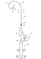
- FIG. 2 is a plan view of a stent delivery device with a stent mounted thereon in an embodiment of the present invention.
- FIG. 2 is a plan view showing a state in which an outer sheath has been removed from a stent delivery device in an embodiment of the present invention. This is a cross-sectional view taken along line AA in FIG.
- FIG. 2 is a perspective view showing the vicinity of the distal end of an inner sheath constituting a stent delivery device in an embodiment of the present invention, and is a perspective view showing typically the vicinity of the distal end of the inner sheath.
- FIG. 2 is a perspective view showing the vicinity of the distal end of an inner sheath constituting a stent delivery device in an embodiment of the present invention, and is a see-through view for explaining the inside of the inner sheath.
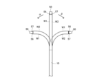
- 11A to 11C are diagrams illustrating the bending motion of a movable part of an inner sheath constituting a stent delivery device in an embodiment of the present invention.
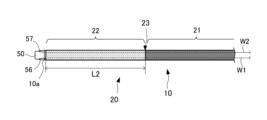
- FIG. 2 is a diagram for explaining the structure of the distal end portion of the inner sheath in an embodiment of the present invention, showing a state in which a stent is not attached to the distal end portion of the inner sheath.
- FIG. 13 is a diagram for explaining the structure of the distal end portion of the inner sheath in an embodiment of the present invention, and illustrates the state in which the second tube portion is compressed when both of the two operating wires are pulled proximally.
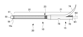
- FIG. 2 is a diagram for explaining the structure of the distal end portion of the inner sheath in an embodiment of the present invention, showing a state in which a stent is attached to the distal end portion of the inner sheath.
- 1 is a plan view showing an outer sheath of a stent delivery device according to an embodiment of the present invention.
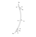
- FIG. 1 is a plan view showing a stent attached to a stent delivery device in an embodiment of the present invention.
- FIG. 1 is a plan view showing an operating device of a stent delivery device in an embodiment of the present invention.
- 1 is a plan view showing a second rack member and a second operating knob included in the operating device of the stent delivery device in an embodiment of the present invention.
- FIG. 3 is a plan view showing a first rack member and a first operating knob included in an operating device of a stent delivery device in an embodiment of the present invention.
- FIG. 1 is a plan view showing a state in which a distal end portion of an inner sheath is deflected in one direction by an operating device of a stent delivery device in an embodiment of the present invention.
- FIG. 13 is a plan view showing a state in which the distal end portion of the inner sheath is deflected in another direction by the operating device of the stent delivery device in the embodiment of the present invention.
- FIG. 1 is a plan view showing a state in which a distal end portion of an inner sheath is compressed by an operating device of a stent delivery device in an embodiment of the present invention.
- FIG. 2 is a conceptual diagram showing an example of use of the stent delivery device in this embodiment, illustrating the first step of stent placement.
- FIG. 2 is a conceptual diagram showing an example of use of the stent delivery device in this embodiment, illustrating the second step of stent placement.
- FIG. 1 is a plan view showing a state in which a distal end portion of an inner sheath is compressed by an operating device of a stent delivery device in an embodiment of the present invention.
- FIG. 2 is a conceptual diagram showing an example of use of the stent delivery device in this embodiment, illustrating
- FIG. 13 is a conceptual diagram showing an example of use of the stent delivery device in this embodiment, illustrating the third step of stent placement.
- FIG. 13 is a conceptual diagram showing an example of use of the stent delivery device in this embodiment, illustrating the fourth step of stent placement.
- FIG. 13 is a conceptual diagram showing an example of use of the stent delivery device in this embodiment, illustrating the fifth step of stent placement.
- FIG. 13 is a conceptual diagram showing an example of use of the stent delivery device in this embodiment, illustrating the sixth step of stent placement.
- a stent delivery device according to an embodiment of the present invention will be described with reference to the drawings.
- the inside of the patient's body is defined as the distal side
- the side closest to the user is defined as the proximal side, based on the user of the stent delivery device.
- the drawings referred to in this specification are not necessarily drawn to exact scale with respect to the actual dimensions, and some parts have been exaggerated or simplified to show the configuration according to the present invention in a schematic manner.
- Figure 1 is a plan view of a stent delivery device 1 with a stent 70 attached in an embodiment of the present invention.
- the stent delivery device 1 in this embodiment is used to place a stent 70 in a puncture hole formed in the wall of a lumen in the body.
- the stent delivery device 1 is generally configured to include an inner sheath 10, an outer sheath 30, a connecting member 60, a Y connector 66, and an operating device 100.
- the stent delivery device 1 also has operating wires W1, W2 (see, for example, Figures 4A and 4B) arranged along the axial direction of the inner sheath 10 so that the operating device 100 can deflect and compress the movable part 20 of the inner sheath 10.
- the inner sheath 10 is a long member made of a flexible material and has a tubular structure with an inner cavity formed along the axial direction.
- the inner sheath 10 has a movable part 20 at the distal end (upper side in Figure 1) that is inserted into the body, which can be deflected left and right.
- a tip chip 50 is attached to the distal end 10a of the inner sheath 10.
- the proximal end 10b of the inner sheath 10 is connected to the operating device 100 (see Figure 9).
- the distal end of the inner sheath 10 can be fitted with a stent 70.
- the stent 70 is formed in a tubular shape, and the distal end of the inner sheath 10 can be fitted to the distal end of the inner sheath 10 by inserting the distal end of the inner sheath 10 through a through hole formed inside the stent 70.
- the stent 70 fitted to the inner sheath 10 is placed in the stent placement section 15, which is a predetermined range of the distal end of the inner sheath 10.
- the stent 70 attached to the distal end of the inner sheath 10 is restricted from moving proximally by the outer sheath 30 disposed on the proximal side of the stent 70.
- the stent 70 is pushed out by the outer sheath 30 and comes out of the distal end 10a and tip tip 50 of the inner sheath 10.
- the outer sheath 30 is attached so as to fit over the proximal end (lower side in FIG. 1) of the inner sheath 10.
- the outer sheath 30 is composed of a tube member with a lumen formed along the axial direction.
- the inner sheath 10 is inserted into the lumen of the outer sheath 30, and the outer sheath 30 is freely movable in the axial direction relative to the inner sheath 10.
- the proximal end of the outer sheath 30 is provided with a connector 35 that is detachably attached to the connector 65 of the connection member 60.
- the connecting member 60 is a member that protects the proximal end of the inner sheath 10 and is configured so that a Y connector 66 can be connected to introduce a contrast agent or a guide wire into the inner cavity of the inner sheath 10.
- the connecting member 60 is a hollow member, and the inner sheath 10 is inserted inside the connecting member 60.
- the proximal end 60b of the connecting member 60 is connected to the distal end 100a of the operating device 100.
- the distal end of the connecting member 60 is provided with a connector 65 that is detachably attached to the connector 35 of the outer sheath 30.
- the operating device 100 is a device for an operator to operate, and is placed outside the body during use.
- the distal end 100a of the operating device 100 is fixed to the proximal end 10b of the inner sheath 10 and the proximal end 60b of the connecting member 60 (see FIG. 9).
- operating wires W1, W2 are attached to the distal end of the inner sheath 10, and the operating device 100 is configured to be able to deflect and compress the movable part 20 of the inner sheath 10 by displacing the operating wires W1, W2 in the axial direction.
- Figure 2 is a plan view showing a state in which the outer sheath 30 has been removed from the stent delivery device 1 in an embodiment of the present invention.
- Figure 3 is a cross-sectional view taken along line A-A in Figure 2.
- the inner sheath 10 is a flexible, long, thin member. When placing the stent 70, the distal end of the inner sheath 10 can be inserted into the body to reach the desired location inside the body.
- the distal end of the inner sheath 10 is provided with a stent placement section 15 for mounting the stent 70.
- the stent placement section 15 is located on the distal side of the outer sheath 30 when the inner sheath 10 is inserted through the outer sheath 30, and the position of the stent placement section 15 can be adjusted appropriately by adjusting the length of the outer sheath 30. Note that the stent placement section 15 may be determined so that the stent 70 can be stably held by providing a section with an outer diameter larger than the through hole of the stent 70 at the distal end of the inner sheath 10.
- the distal end of the inner sheath 10 is provided with a movable part 20 that can be bent and compressed using the operating device 100. Note that bending in this specification includes curving in the shape of a bow.
- the inner sheath 10 has a tubular structure with a lumen formed along its extension direction.
- a main lumen 11 is formed along the axial direction of the inner sheath 10 at approximately the center of the cross-section of the inner sheath 10.
- the main lumen 11 is formed so as to open at the distal end 10a and the proximal end 10b of the inner sheath 10.
- Wire lumens 11a, 11b, 12a, 12b for inserting the first and second operating wires W1, W2 are formed in the tube wall between the outer peripheral surface of the inner sheath 10 and the main lumen 11.
- the inner sheath 10 is formed with a pair of wire lumens 11a, 11b and a pair of wire lumens 12a, 12b, i.e., a total of four wire lumens 11a, 11b, 12a, 12b.
- Each of the wire lumens 11a, 11b, 12a, 12b is formed to open at the distal end 10a and proximal end 10b of the inner sheath 10, similar to the main lumen 11.
- a first operating wire W1 is inserted through the pair of wire lumens 11a, 11b, and a second operating wire W2 is inserted through the pair of wire lumens 12a, 12b.
- the pair of wire lumens 11a, 11b and the pair of wire lumens 12a, 12b are respectively provided at positions that are mutually opposite, approximately 180 degrees, with respect to the central axis of the inner sheath 10.
- the inner sheath 10 is preferably set to appropriate dimensions according to the placement site of the stent 70, and although there is no particular limitation, the radial dimension can be, for example, about 2 to 20 mm, and the axial dimension can be, for example, about 20 to 300 cm.
- the range of the movable part 20 can be appropriately set according to the placement site of the stent 70, and although there is no particular limitation, it can be, for example, in the range of about 2 to 10 cm from the distal end 10a of the inner sheath 10 (i.e., the dimension L1 in Figure 2 is about 2 to 10 cm).
- the material of the inner sheath 10 is preferably a flexible material that allows the inner sheath 10 to be flexibly deformed when inserted into the body and is also a material that is not harmful to the human body, and may be a biocompatible polymer material such as polyurethane, polyethylene, polypropylene, or a fluororesin such as polytetrafluoroethylene, and it is particularly preferable to use polytetrafluoroethylene.
- the inner sheath 10 in this embodiment is configured to include a first tube portion (solid structure portion) 21 on the proximal side and a second tube portion (porous structure portion) 22 on the distal side, as will be described later with reference to Figures 6A, 6B, and 6C.
- the inner sheath 10 may be provided with a braided layer in which a reinforcing member made of braided wire material such as stainless steel is arranged.
- the inner sheath 10 may have multiple lumens or may be a multi-layer tube.
- Figure 4A is a perspective view showing the vicinity of the distal end 10a of the inner sheath 10 constituting the stent delivery device 1 in an embodiment of the present invention, and is a perspective view that typically shows the vicinity of the distal end 10a of the inner sheath 10.
- Figure 4B is a perspective view showing the vicinity of the distal end of the inner sheath constituting the stent delivery device in an embodiment of the present invention, and is a see-through view for explaining the inside of the inner sheath. Note that the main lumen 11 is omitted in Figure 4B.
- Figure 5 is a view for explaining the bending operation of the movable part 20 of the inner sheath 10 constituting the stent delivery device 1 in an embodiment of the present invention.
- the distal end 10a of the inner sheath 10 is provided with a tip tip 50 made of, for example, metal.
- the tip tip 50 protects the distal end 10a of the inner sheath 10 and also serves to reduce the insertion resistance of the inner sheath 10 into the body.
- the tip tip 50 is fixed to the distal end 10a of the inner sheath 10.
- by forming the tip tip 50 into a tapered shape it is possible to improve the ease of insertion into a puncture hole formed in the wall of a lumen in the body and the ability to break through body tissue.
- the distal tip 50 has a through hole 55a along its central axis.
- the through hole 55a is connected to the main lumen 11 of the inner sheath 10, and the main lumen 11 of the inner sheath 10 is connected to the outside through this through hole 55a.
- the distal tip 50 has a pair of recesses 56, 57 formed on its proximal side.
- Wire insertion holes 56a, 56b are formed in the recess 56.
- wire insertion holes 57a, 57b are formed in the recess 57.
- the wire insertion holes 56a, 56b, 57a, 57b are provided to correspond to the opening positions of the wire lumens 11a, 11b, 12a, 12b that open at the distal end 10a of the inner sheath 10, respectively, and the first and second operating wires W1, W2 inserted into the wire lumens 11a, 11b, 12a, 12b are inserted into the wire insertion holes 56a, 56b, 57a, 57b, respectively.
- first operating wire W1 is inserted through the wire lumens 11a and 11b
- second operating wire W2 is inserted through the wire lumens 12a and 12b.
- the first operating wire W1 and the second operating wire W2 are made of a metal (stainless steel, etc.) that is flexible enough to bend in accordance with the curvature of the inner sheath 10 including the movable part 20.
- the first operating wire W1 which is inserted through the wire lumens 11a and 11b, is inserted through the wire insertion holes 56a and 56b of the distal tip 50, which are provided corresponding to the wire lumens 11a and 11b.
- the first operating wire W1 is folded back at the folded back intermediate portion W1c, which corresponds to approximately halfway along the axial direction of the wire, in the recess 56 of the distal tip 50.
- the folded back intermediate portion W1c as a reference, the operating wire W1a on one end side is inserted through the wire lumen 11a via the wire insertion hole 56a, and the operating wire W1b on the other end side is inserted through the wire lumen 11b via the wire insertion hole 56b.
- the operating wires W1a and W1b are pulled proximally, and the folded back intermediate portion W1c is configured to engage with the distal tip 50 due to the tensile force.
- the second operating wire W2 which is inserted through the wire lumens 12a and 12b, is inserted through the wire insertion holes 57a and 57b of the distal tip 50, which are provided corresponding to the wire lumens 12a and 12b.
- the second operating wire W2 is folded back at the folded back intermediate portion W2c, which corresponds to approximately halfway along the axial direction of the wire, in the recess 57 of the distal tip 50.
- the folded back intermediate portion W2c as a reference, the operating wire W2a on one end side is inserted through the wire lumen 12a via the wire insertion hole 57a, and the operating wire W2b on the other end side is inserted through the wire lumen 12b via the wire insertion hole 57b.
- the operating wires W2a and W2b are pulled proximally, and the folded back intermediate portion W2c is configured to engage with the distal tip 50 by the tensile force.
- the operation wire W1a on one end side constituting the first operation wire W1 extends along the inner sheath 10 while being inserted into the wire lumen 11a, and the proximal end of the operation wire W1a is guided inside the operation device 100.
- the operation wire W1b on the other end side constituting the first operation wire W1 extends along the inner sheath 10 while being inserted into the wire lumen 11b, and the proximal end of the operation wire W1b is guided inside the operation device 100.
- the proximal end of the operation wire W1a and the proximal end of the operation wire W1b are connected and fixed to the first rack member 200 of the operation device 100.
- the operation wire W2a at one end of the second operation wire W2 extends along the inner sheath 10 while being inserted into the wire lumen 12a, and the proximal end of the operation wire W2a is guided inside the operation device 100.
- the operation wire W2b at the other end of the second operation wire W2 extends along the inner sheath 10 while being inserted into the wire lumen 12b, and the proximal end of the operation wire W2b is guided inside the operation device 100.
- the proximal end of the operation wire W2a and the proximal end of the operation wire W2b are connected and fixed to the second rack member 300 of the operation device 100.
- the longitudinal middle portion 10c including the proximal end of the inner sheath 10 is preferably flexible and deformable to match the path along which the stent 70 is transported inside the body, and has excellent mechanical strength such as rigidity.
- the movable portion 20 located at the distal end of the inner sheath 10 is preferably flexible and deflectable by the user's operation.
- the distal end of the inner sheath 10 where the movable portion 20 is provided is preferably capable of deflecting in response to the deflection operation by the operating device 100, and preferably has higher flexibility than the middle portion 10c of the inner sheath 10.
- the inner sheath 10 in this embodiment has a portion with excellent flexibility on the distal side constituting the movable portion 20, and a portion with excellent mechanical strength on the proximal side including the intermediate portion 10c.
- the inner sheath 10 in this embodiment has both flexibility and rigidity, making it easy to operate.
- Figure 6A is a diagram for explaining the structure of the distal end of the inner sheath 10 in an embodiment of the present invention, and is a diagram showing a state in which a stent 70 is not attached to the distal end of the inner sheath 10.
- Figure 6B is a diagram for explaining the structure of the distal end of the inner sheath in an embodiment of the present invention, and is a diagram showing a state in which the second tube portion is compressed when both of the two operating wires are pulled proximally.
- Figure 6C is a diagram for explaining the structure of the distal end of the inner sheath in an embodiment of the present invention, and is a diagram showing a state in which a stent 70 is attached to the distal end of the inner sheath 10. Note that the proximal side of the stent 70 is omitted in Figure 6C.
- the tube member constituting the inner sheath 10 has a first tube portion 21 on the proximal side and a second tube portion 22 that is connected to the distal end of the first tube portion 21 so as to be continuous with it.
- the first tube section 21 is a solid structural section whose flexibility does not change substantially even when subjected to a compressive force in the axial direction.
- the first tube section 21 is disposed mainly in the middle section 10c of the inner sheath 10 and constitutes the inner sheath 10.
- the second tube section 22 is a porous structure section made of a porous tube that is compressed and hardened according to the degree of compressive force acting in the axial direction, and returns to its original soft state when the compressive force is released.
- the second tube section 22 is continuous with the first tube section 21, and constitutes the range from the boundary section 23 with the first tube section 21 to the distal end 10a of the inner sheath 10.
- the length of the second tube portion 22 from the distal end 10a of the inner sheath 10 to the boundary portion 23 is not particularly limited, and the dimension L2 in the longitudinal direction of the second tube portion 22 may be shorter or longer than the dimension in the longitudinal direction of the movable portion 20 (dimension L1 in FIG. 2), or may be the same.
- the movable portion 20 can be provided so as to include at least a portion of the second tube portion 22.
- Both the first tube portion 21 and the second tube portion 22 can be made of a biocompatible polymeric material, such as polyurethane, polyethylene, polypropylene, or a fluororesin such as polytetrafluoroethylene.
- the first tube portion 21 and the second tube portion 22 are preferably made of the same material, but may be made of different materials.
- the inner sheath 10 is preferably made of the first tube portion 21 and the second tube portion 22, both of which are made of polytetrafluoroethylene.
- the first tube portion 21 and the second tube portion 22 may each be a single-layer tube made of a single material, or may be made by laminating multiple layers made of different materials.
- a specific example of the first tube portion 21 made by laminating multiple layers is a configuration in which a polytetrafluoroethylene tube constituting the inner layer is covered with a fluororesin heat-shrinkable tube.
- the second tube section 22 is characterized by being porous and containing more pores than the first tube section 21.
- the first tube section 21 and the second tube section 22 each have different physical properties, as exemplified below.
- the specific gravity of the first tube section 21 is not particularly limited, but is preferably 0.80 to 2.20.
- the specific gravity of the second tube section 22 is not particularly limited, but is preferably 0.10 to 2.00.
- the ratio of the specific gravity of the first tube section 21 to the specific gravity of the second tube section 22 (second tube section 22/first tube section 21) is preferably 0.30 to 0.95, more preferably 0.40 to 0.90, and even more preferably 0.50 to 0.90 in at least a portion of the length of the inner sheath 10.
- the proximal side of the inner sheath 10 has excellent rigidity due to the action of the first tube section 21, and the distal side of the inner sheath 10 has excellent flexibility due to the action of the second tube section 22.
- the specific gravity test method complies with the liquid weighing method described in JIS Z 8807, and the standard substance is water.
- the ratio of the radial crushing strength of the first tube section 21 to the radial crushing strength of the second tube section 22 is preferably 0.20 or more and less than 1.0.
- the ratio of the radial crushing strength is 0.50 or more and less than 1.0, a certain radial crushing strength can be secured even in the second tube section 22, and the inner sheath 10 has excellent mechanical strength.
- the ratio of the radial crushing strength is 0.20 or more and less than 0.50, the inner sheath 10 has excellent mechanical strength and flexibility.
- the radial crushing strength was measured by performing a radial compression test using a bending and crushing rigidity measuring device, and measuring the reaction force when pressed 0.5 mm.
- the tube length was 10 mm
- the shape of the compressed section was flat
- the pressing speed was 1.0 mm/min.
- the ratio of the bending stress in the first tube section 21 to the bending stress in the second tube section 22 is preferably 0.10 or more and less than 1.0.
- the ratio of the bending stress is 0.40 or more and less than 1.0, a certain bending stress can be secured in the second tube section 22 as well, and the inner sheath 10 has excellent mechanical strength.
- the ratio of the bending stress is 0.10 or more and less than 0.40, the inner sheath 10 has excellent mechanical strength and flexibility.
- the bending stress was measured by performing a bending test using a bending and crushing stiffness measuring device and measuring the reaction force when pressed 5.0 mm.
- the tube length is 100 mm
- the compressed section shape is cylindrical with a diameter of 10 mm
- the support distance is 60 mm
- the support member shape is cylindrical with a diameter of 10 mm
- the pressing speed is 50 mm/min.
- the ratio of the kink resistance of the first tube section 21 to the kink resistance of the second tube section 22 is preferably 20% or more and less than 100%, more preferably 20-90%, and even more preferably 20-80%.
- the kink resistance is measured by performing a buckling test using a vice and measuring the distance between the vises when the tube is completely buckled. A 300 mm long tube is bent and clamped in a vice with a width of about 200 mm, and the distance between the vises is gradually reduced until the tube is completely buckled. The distance between the vises when the tube buckles is the measured value. The smaller this measured value, the more kink resistant the tube is.
- the structure of the boundary 23 between the first tube section 21 and the second tube section 22 is not particularly limited.
- a transition section whose structure changes gradually may be provided at the boundary 23 between the first tube section 21 and the second tube section 22.
- the longitudinal dimension of the transition section is not particularly limited.
- the load is not concentrated at a single point when the inner sheath 10 is bent, so the inner sheath 10 is less likely to break or be crushed when bent, and the kink resistance of the inner sheath 10 is improved.
- the radial crushing strength of the inner sheath 10 is improved by the action of the first tube section 21, and the rigidity of the inner sheath 10 can be increased.
- the second tube portion 22 itself may be gradually changed to a structure having greater flexibility as it approaches the distal side of the inner sheath 10. This increases flexibility and bendability as it approaches the distal side of the inner sheath 10, improving the operational responsiveness of the movable portion 20 provided at the distal end of the inner sheath 10. Furthermore, the flexibility and bendability of the inner sheath 10 gradually increases toward the distal side without any sudden changes, resulting in a configuration that is suited to the movable portion 20, which bends more significantly on the distal side, and allowing the movable portion 20 to be deflected smoothly.
- the inner and outer circumferential surfaces of the inner sheath 10 are smooth without any seams or steps in the first tube portion 21, the second tube portion 22, and the boundary portion 23 between the first tube portion 21 and the second tube portion 22.
- various treatment tools can be smoothly inserted into the main lumen 11.
- the outer circumferential surface of the inner sheath 10 can be smoothly inserted into a puncture hole formed in the wall of a lumen in the body or a channel of an endoscope, and the stent 70 can be smoothly attached to and removed from the inner sheath 10.
- the insertion resistance of the inner sheath 10 increases in this portion, and operability is significantly reduced.
- the method of manufacturing the inner sheath 10 is not particularly limited, and examples of the method include extrusion molding, injection molding, and a method of wrapping a film into a tube shape. If necessary, stretching, chemical treatment, plasma treatment, laser treatment, electronic cross-linking, etc. may be performed.
- an unsintered tube may be manufactured by extrusion molding, and only the portion corresponding to the first tube portion 21 may be sintered. Then, the portion corresponding to the second tube portion 22 may be stretched to make it porous, and then sintered to manufacture the inner sheath 10 having the first tube portion 21 and the second tube portion 22 as an integrated tube.
- the second tube portion 22 is preferably isotropic in the radial direction of the inner sheath 10. This allows the second tube portion 22 to have similar flexibility in any direction, making it easier to position the movable portion 20, which includes at least a portion of the second tube portion 22.
- the second tube section 22 is a porous tube and is configured to include numerous voids (holes) therein.
- voids holes
- the folded-back intermediate portions W1c, W2c of the two operating wires W1, W2 are engaged so as to be folded back at the distal end 10a of the inner sheath 10, and the operating wires W1, W2 can be displaced in the axial direction by the operating device 100.
- the deflection operation of the movable part 20 can be performed by moving either the first rack member 200 or the second rack member 300 proximally, but a compression operation can also be performed by simultaneously moving both the first rack member 200 and the second rack member 300 proximally.
- both the first rack member 200 and the second rack member 300 move proximally at the same time, both of the two operating wires W1 and W2 are pulled proximally at the same time, and a force that pulls the distal end 10a of the inner sheath 10 proximally acts on the distal end 10a of the inner sheath 10.
- This force acts as a compressive force that compresses the inner sheath 10 in the axial direction.
- the first tube portion 21 is hardly compressed and its axial length does not change, while the second tube portion 22 is subjected to an axial compressive force and compressed so that its axial length (dimension L3 in FIG. 6B) becomes shorter than its length when no compressive force is applied (dimension L2 in FIG. 6A).
- first tube portion 21 is also compressed to a certain extent so that its axial length becomes shorter, but the second tube portion 22, which is made of a porous structure, is more significantly affected by the axial compressive force, and the characteristics of the second tube portion 22 change significantly.
- the second tube portion 22 When the second tube portion 22 is subjected to a compressive force, it becomes harder and has higher rigidity than the second tube portion 22 when it is not subjected to a compressive force. Furthermore, when the axial compressive force applied by the two operating wires W1 and W2 is released, the second tube portion 22 returns to its original state, becomes soft, and recovers its flexibility.
- the stent delivery device 1 in this embodiment can be freely changed between a state in which the second tube portion 22 is hard and has high rigidity, and a state in which the second tube portion 22 is soft and has high flexibility, by operating the operating device 100.
- the rigidity of the second tube portion 22 is high, and the insertability into the puncture hole is improved.
- the second tube portion 22 is soft, the flexibility of the second tube portion 22 is high, and the second tube portion 22 can be flexibly deflected.
- the stent 70 is also mounted on the stent placement section 15 at the distal end of the inner sheath 10.
- the stent 70 mounted on the stent placement section 15 is preferably mounted at a position that does not cover the movable section 20 so as not to interfere with the deflection of the movable section 20.
- the stent placement section 15 is provided on the first tube section 21, and the stent 70 mounted on the stent placement section 15 of the inner sheath 10 is disposed proximal to the boundary section 23 between the first tube section 21 and the second tube section 22.
- the second tube section 22 can be changed between a hard state and a soft state by the operation of the operating device 100, but by disposing the stent 70 proximal to the boundary section 23, the stent 70 can be transported stably without being affected by the change in state of the second tube section 22, and the movable section 20 provided on the second tube section 22 can be smoothly operated without being affected by the positioning of the stent 70.
- the second tube portion 22 is made of a porous structure containing many voids (holes) therein, and has a structure that is easily visible in an ultrasound image that visualizes a reflected signal from the interface of materials.
- the second tube portion 22 made of a porous structure has excellent ultrasound visibility.
- connection member 60 is configured to integrally include a tubular first protective member 61, a branching member 62, and a tubular second protective member 63, and is disposed on the distal side of the operating device 100.
- the connection member 60 is a hollow member formed separately from the inner sheath 10 and the operating device 100, and is made of a metal such as stainless steel.
- the inner sheath 10 is inserted and fixed inside the first protective member 61 and the second protective member 63, and in this section the inner sheath 10 is protected by the first protective member 61 and the second protective member 63.
- the branching member 62 is interposed between the first protective member 61 and the second protective member 63 to protect the inner sheath 10, and is configured to allow a Y connector 66 that communicates with the main lumen 11 of the inner sheath 10 to be attached.
- the main lumen 11 is blocked at the position where it communicates with the Y connector 66 or proximal thereto, so that contrast medium, etc. introduced into the main lumen 11 does not leak from the proximal end 10b of the inner sheath 10.
- the Y connector 66 is a hollow member formed separately from the inner sheath 10, the operating device 100, and the connection member 60.
- the Y connector 66 is formed, for example, by injection molding of resin.
- the Y connector 66 has a sleeve portion that is inserted into the branching member 62 and is bifurcated into a first port portion 67 and a second port portion 68.
- the first port portion 67 has an opening with a valve or the like on its proximal side.
- a contrast agent or the like can be introduced from the opening of the first port portion 67, so that a contrast agent or the like can be introduced into the main lumen 11 of the inner sheath 10.
- the second port portion 68 has an opening whose opening diameter can be adjusted by the handle portion 69.
- a guidewire or the like can be introduced from the opening of the second port portion 68, so that the guidewire or the like can be introduced into the main lumen 11 of the inner sheath 10.
- connection member 60 The proximal end 60b of the connection member 60 is connected to the distal end 100a of the operating device 100.
- a connector 65 is provided at the distal end of the connection member 60.
- the inner sheath 10 can be inserted into the inside of the connector 65, and the inner sheath 10 extends from the distal end opening 65a of the connector 65 through the inside of the connection member 60 to the operating device 100.
- the connector 65 is configured to be detachable from the connector 35 provided at the proximal end of the outer sheath 30.
- the connector 65 is made of, for example, polycarbonate, high-density polyethylene, polymethylpentene, polyacetal, polyamide, polypropylene, etc.
- the method of connecting the distal end of the connection member 60 to the connector 65 is not particularly limited, and for example, bonding with an adhesive, fusion, crimping, etc. can be used.
- Figure 7 is a plan view showing the outer sheath 30 of the stent delivery device 1 in an embodiment of the present invention.
- the outer sheath 30 is a flexible, long, thin-diameter member.
- the outer sheath 30 is made of a tube member that can be attached to the outer periphery of the inner sheath 10, and is used as an extrusion member that pushes the stent 70 attached to the stent placement section 15 of the inner sheath 10 distally.
- the lumen formed inside the outer sheath 30 opens at a distal end opening 30a located at the distal end of the outer sheath 30 and a proximal end opening 30b located at the proximal end of the outer sheath 30.
- a connector 35 is provided at the proximal end of the outer sheath 30.
- a base end opening 35b is formed at the proximal end of the connector 35.
- the inner sheath 10 can be inserted into the lumen of the outer sheath 30 by inserting the distal end 10a (distal tip 50) of the inner sheath 10 from this base end opening 35b. That is, inside the connector 35 and outer sheath 30 shown in FIG. 7, a through hole is formed that communicates from the base end opening 35b to the distal end opening 30a, and the inner diameter of the through hole is equal to or greater than the maximum outer diameter of the inner sheath 10.
- the connector 35 is configured to be detachable from the connector 65 provided at the distal end of the connection member 60.
- the connector 35 of the outer sheath 30 is attached to the connector 65 of the connection member 60, the outer sheath 30 is fixed to the connection member 60 and the inner sheath 10 and cannot move in the axial direction.
- the connector 35 of the outer sheath 30 is detached from the connector 65 of the connection member 60, the outer sheath 30 is separated from the connection member 60 and becomes movable relative to the inner sheath 10 in the axial direction.
- the material of the tube member that constitutes the outer sheath 30 is not particularly limited, and may be, for example, a fluororesin such as polytetrafluoroethylene, polyethylene, polyurethane, polyamide, or the like.
- the connector 35 is made of, for example, polycarbonate, high-density polyethylene, polymethylpentene, polyacetal, polyamide, polypropylene, or the like.
- the method of connecting the proximal end of the outer sheath 30 and the connector 35 is not particularly limited, and may be, for example, adhesive bonding, fusion, crimping, or the like.
- the stent 70 is configured to have a flexible tube body 72.
- the tube body 72 has a through hole formed therein, and has a distal end opening 72a that opens at the distal end of the tube body 72, and a proximal end opening 72b that opens at the proximal end of the tube body 72.
- the tube body 72 can be configured from a plastic tube made of, for example, a fluororesin such as polytetrafluoroethylene, polyethylene, polyurethane, polyamide, or the like.
- the distal end of the tube body 72 is tapered so that its outer diameter and inner diameter decrease toward the distal side, and the inner diameter of the distal end opening 72a is smaller than the inner diameter of the tube body 72.
- a side hole 78 is formed on the proximal side of the distal end opening 72a of the tube body 72. The side hole 78 is connected to a through hole inside the tube body 72.
- a distal end flap 74 is formed proximal to the side hole 78.
- the distal end flap 74 is formed by cutting the outer periphery of the tube body 72 in the axial direction along the flap opening 74a and raising the cut piece to the outside of the tube body 72.
- the through hole of the tube body 72 is in communication with the outside through the flap opening 74a.
- the distal end opening 72a, the side hole 78, and the flap opening 74a have the function of taking in bile and the like into the inside of the stent 70.
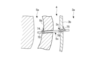
- the distal end flap 74 gradually protrudes outward from the base end of the distal end flap 74 in the proximal end direction so that when the stent 70 is inserted distally into a puncture hole in the body lumen wall, it is folded along the inner wall of the puncture hole toward the tube body 72.
- the distal end flap 74 is positioned so that it spreads outward within the body lumen (e.g., the intrahepatic bile duct), and functions as an engagement member that hooks onto the body lumen wall (e.g., the intrahepatic bile duct wall).
- a proximal end flap 75 is formed on the distal side of the proximal end opening 72b of the tube body 72.
- the proximal end flap 75 is formed by cutting the outer periphery of the tube body 72 in the axial direction along the flap opening 75a and raising the cut piece to the outside of the tube body 72.
- the through hole of the tube body 72 is connected to the outside through the flap opening 75a.
- the proximal end opening 72b and the flap opening 75a have the function of discharging bile and the like that has been taken into the internal through hole from the distal side of the stent 70.
- the proximal end flap 75 gradually protrudes outward from the base end of the proximal end flap 75 in the direction of the distal end.
- the proximal end flap 75 is disposed so as to spread outward within the body lumen (e.g., the stomach) and functions as an engagement member that hooks onto the wall of the body lumen (e.g., the stomach wall).
- a marker 76 may be provided on the distal side of the proximal end flap 75.
- the marker 76 may be colored so that it is visible in an image captured by an endoscopic camera.
- the marker 76 may be formed by attaching a metal ring made of, for example, platinum, gold, or a platinum-iridium alloy so that its position can be detected in an X-ray fluoroscopic image.
- the tube body 72 is preferably formed into an arc shape with a predetermined radius of curvature, for example, so as to fit the shape of the placement site inside the body.
- the predetermined radius of curvature is not particularly limited, but is preferably 40 to 200 mm.
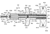
- Figure 9 is a plan view showing the operating device 100 of the stent delivery device 1 in an embodiment of the present invention.
- Figure 9 shows the internal configuration of the operating device 100 in a see-through manner.
- Figure 10A is a plan view showing the second rack member 300 and the second operating knob 520 included in the operating device 100 of the stent delivery device 1 in an embodiment of the present invention.
- Figure 10B is a plan view showing the first rack member 200 and the first operating knob 510 included in the operating device 100 of the stent delivery device 1 in an embodiment of the present invention.
- the operating device 100 includes a flat controller housing 400 having an internal cavity, a first rack member 200 and a second rack member 300 housed within the controller housing 400, and a pinion member 500 disposed between the first rack member 200 and the second rack member 300.
- the controller housing 400 is formed in a roughly T-shape with an internal cavity, and has a roughly rectangular main body 410, a support handle portion 420 integrally provided at the proximal end, which is one end side in the longitudinal direction of the main body 410, and a wire insertion portion 430 at the distal end, which is the other end side in the longitudinal direction of the main body 410, through which the first operating wire W1 and the second operating wire W2 are respectively inserted.
- the longitudinal direction of the main body 410 is the direction along the extension direction of the operating wires W1, W2 inserted into the inner sheath 10.
- the longitudinal direction referred to below is based on the longitudinal direction of this main body 410.
- the controller housing 400 has a symmetrical shape with the longitudinal center line C passing through the center of the width of the main body 410 as the line of symmetry.
- the controller housing 400 is configured, for example, by combining a halved base and a lid body, which are roughly divided into two equal halves in the thickness direction, in a removable manner.
- the base and lid body that configure the controller housing 400 can be secured together by screwing, gluing, etc., when stacked facing each other.
- the base and lid body are roughly the same shape and are each made of resin, etc.
- a first slide guide portion 406 and a second slide guide portion 407 are formed on both side surfaces of the controller housing 400.
- An opening is formed on the side surface of the first slide guide portion 406 for exposing the first operation knob 510 of the first rack member 200 to the side, and an opening is formed on the side surface of the second slide guide portion 407 for exposing the second operation knob 520 of the second rack member 300 to the side.
- the support handle portion 420 of the controller housing 400 includes a first handle portion 421 and a second handle portion 422, each of which is substantially rectangular and extends laterally perpendicular to the main body portion 410.
- the support handle portion 420 and the main body portion 410 form a substantially T-shape.
- the proximal edge 423 of the support handle portion 420 includes a support portion 423a against which the operator's palm rests.
- This support portion 423a is formed into a gently curved surface that is generally convex from one end to the other toward the proximal side. Corners 423b, 423c continuing to both ends of the support portion 423a are chamfered. Because the support portion 423a is gently curved and each corner 423b, 423c is chamfered, the operator can easily place his or her palm against the support portion 423a without feeling uncomfortable, thereby improving the operability of the operating device 100.
- the distal end edges of the first handle portion 421 and the second handle portion 422 that constitute the support handle portion 420 respectively constitute finger locking portions 421a, 422a on which the operator's fingers can be hooked.
- These finger locking portions 421a, 422a are formed into gently curved surfaces that are roughly concave toward the proximal side.
- the outer corners 421b, 422b that are continuous with the finger locking portions 421a, 422a are chamfered.
- the support handle portion 420 forms an approximately T-shape together with the main body portion 410, but it may be any shape that has a surface that can be pressed against the palm, such as a shape that forms an approximately L-shape together with the main body portion 410, or it may be any shape that has a structure that allows fingers to be engaged, such as a finger insertion ring that can be supported by passing the fingers through.
- the wire insertion portion 430 has a thin tubular sleeve portion 431 protruding from the distal end of the controller housing 400, a wire inlet 432 that communicates from the inside of the sleeve portion 431 to the inside of the controller housing 400, and a gate portion 433 disposed adjacent to the wire inlet 432.
- the gate portion 433 includes a pair of cylindrical portions 433a, 433b provided on the controller housing 400.
- the cylindrical portions 433a, 433b that constitute the gate portion 433 may be formed of rotatable rollers.
- the inner sheath 10 has its proximal end 10b fixed inside the sleeve portion 431 and is connected to the controller housing 400.
- the means for fixing the inner sheath 10 to the sleeve portion 431 but for example, a means can be used in which the proximal end 10b of the inner sheath 10 is pressed into the sleeve portion 431 and then glued or welded to the inner surface of the sleeve portion 431.
- a heat shrink tube or the like can be used to cover the boundary position between the controller housing 400 and the inner sheath 10, and the cover can be integrated with the controller housing 400.
- the connecting member 60 has its proximal end 60b fixed to the outer periphery of the sleeve portion 431 and is connected to the controller housing 400.
- the means for fixing the inner sheath 10 to the sleeve portion 431 is not particularly limited, but for example, a means can be used in which the sleeve portion 431 is press-fitted into the proximal end 60b of the connecting member 60 and then glued or welded to the inner surface of the proximal end 60b of the connecting member 60.
- the connecting member 60 and the controller housing 400 may be formed integrally.
- the proximal ends of the first operating wire W1 and the second operating wire W2 are passed from inside the sleeve portion 431 through the wire inlet 432 and between the cylindrical portions 433a, 433b of the gate portion 433, and introduced into the controller housing 400. As described below, the first operating wire W1 is fixed to the first rack member 200, and the second operating wire W2 is fixed to the second rack member 300.
- the controller housing 400 has therein a first guide portion 451 that guides the first rack member 200 so that it can be displaced back and forth in the longitudinal direction, and a second guide portion 452 that guides the second rack member 300 so that it can be displaced back and forth in the longitudinal direction.
- the first guide section 451 is formed by two partition walls 441a, 442a extending in the longitudinal direction provided at the center of the controller housing 400, the first slide guide section 406, and a guide wall section 443 within the support handle section 420.
- the second guide section 452 is formed by partition walls 441b, 442b, the second slide guide section 407, and a guide wall section 444 within the support handle section 420.
- a coil spring 455 is disposed on the proximal side of the first guide portion 451, and a coil spring 456 is disposed on the proximal side of the second guide portion 452.
- the coil springs 455, 456 bias the first rack member 200 and the second rack member 300 that have moved to the proximal side, respectively, and serve to return the first rack member 200 and the second rack member 300 to a neutral position in which they are positioned symmetrically on the left and right.
- the coil springs may be disposed on the distal side of the first guide portion 451 and the distal side of the second guide portion 452, or a configuration may be adopted in which no coil springs are provided.
- the partition wall portions 441a and 441b form a partition wall on the distal side in the longitudinal direction, and the proximal ends of the partition wall portions 441a and 441b are connected by a U-shaped curved portion 441c near the position where the pinion member 500 is disposed.
- the partition wall portions 442a and 442b form a partition wall on the proximal side in the longitudinal direction, and the distal ends of the partition wall portions 442a and 442b are connected by a U-shaped curved portion 442c near the position where the pinion member 500 is disposed.
- the curved portion 441c and the curved portion 442c are arranged to be spaced apart in the longitudinal direction, and a space in which the pinion member 500 is disposed is formed.
- the base of the controller housing 400 has a groove 460 between the curved portions 441c and 442c. Although not shown, a groove is also provided at the opposing position of the lid of the controller housing 400. This forms grooves that extend along the longitudinal direction so as to face each other vertically.
- the pinion member 500 is disposed between the curved portions 441c and 442c with its pivot shaft 502 fitted into the groove formed by the groove 460 (and the opposing groove of the lid), and is supported so as to be movable along the longitudinal direction and rotatable.
- the first operating wire W1 and the second operating wire W2 are introduced into the controller housing 400 from the proximal end 10b of the inner sheath 10, branched at cylindrical wire guides 434a and 434b, and guided to the first guide portion 451 and the second guide portion 452, respectively.
- the wire guides 434a and 434b may be composed of rotatable rollers.
- the first operating wire W1 guided to the first guide portion 451 is connected to the first rack member 200.
- the second operating wire W2 guided to the second guide portion 452 is connected to the second rack member 300.
- the first rack member 200 and the second rack member 300 are housed within the controller housing 400 so that they can be moved back and forth in the longitudinal direction of the main body 410, and so that the teeth 220, 320 face each other.
- the first rack member 200 and the second rack member 300 each have an elongated rectangular parallelepiped rack body 210, 310 and a tooth section 220, 320 consisting of a large number of teeth provided on the side surfaces of the rack body sections 210, 310 that face each other.
- the first rack member 200 and the second rack member 300 are installed in the first guide section 451 and the second guide section 452, respectively, with the tooth sections 220, 320 facing each other.
- the rack body 210 of the first rack member 200 has a guide piece 212 on its outer side surface 211 that extends in the longitudinal direction of the rack body 210.
- This guide piece 212 is inserted into an opening formed in the side surface of the first slide guide portion 406.
- a first operation knob 510 that protrudes through this opening to the side of the controller housing 400 is integrally provided on the rack body 210 of the first rack member 200.
- the rack body 310 of the second rack member 300 has a guide piece 312 on its outer side surface 311 that extends in the longitudinal direction of the rack body 310.
- This guide piece 312 is inserted into an opening formed in the side surface of the second slide guide portion 407.
- a second operation knob 520 that protrudes through this opening to the side of the controller housing 400 is integrally provided on the rack body 310 of the second rack member 300.
- the first and second operating knobs 510 and 520 have a rectangular plate shape similar to the first and second handle portions 421 and 422 constituting the support handle portion 420, respectively, and are formed integrally with the first and second rack members 200 and 300, respectively.
- the first and second operating knobs 510 and 520 may have any shape, for example, a rod shape, a ring shape, a trigger shape, etc.
- the first and second operating knobs 510 and 520 may be formed separately from the first and second rack members 200 and 300, respectively, and then fixed to the first and second rack members 200 and 300, respectively.
- the distal edges (left side in Figs. 10A and 10B) of the first operation knob 510 and the second operation knob 520 respectively constitute finger locks 510a, 520a on which the operator's fingers can be hooked.
- These finger locks 510a, 520a are formed into gently curved surfaces that are generally concave toward the proximal side.
- the outer corners 510b, 520b that are continuous with the finger locks 510a, 520a are chamfered.
- Each finger lock 510a, 520a is curved into a concave shape so that the operator can easily hook the fingers on the finger locks 510a, 520a, making it easy to operate the first operation knob 510 and the second operation knob 520.
- each finger retaining portion 510a, 520a is formed with an inner convex portion 510c, 520c that is shaped to smoothly transition to the first rack member 200 and the second rack member 300, respectively.
- These inner convex portions 510c, 520c make it difficult for fingers placed on each finger retaining portion 510a, 520a to come into contact with the main body portion 410 of the controller housing 400, and thus the operability of the first operating knob 510 and the second operating knob 520 is not hindered.
- the first operating knob 510 and the second operating knob 520 are operated by pulling them proximally (towards the support handle portion 420) with fingers hooked on the finger engagement portions 510a, 520a.
- the first rack member 200 is displaced integrally to the proximal side, and in sync with this, the second rack member 300 is displaced distally in the opposite direction.
- the second rack member 300 is displaced integrally to the proximal side, and in sync with this, the first rack member 200 is displaced distally in the opposite direction.
- the index finger can be placed on the finger retaining portion 510a of the first operation knob 510 and the middle finger can be placed on the finger retaining portion 520a of the second operation knob 520, and the first operation knob 510 and the second operation knob 520 can be pulled and operated with each finger.
- the first rack member 200 has a wire fixing portion 511 on its back surface for fixing the proximal end of the first operating wire W1.
- the second rack member 300 has a wire fixing portion 521 on its front surface for fixing the proximal end of the second operating wire W2.
- Each wire fixing portion 511, 521 has the same structure, and the operating wires W1, W2 can be fixed to the first rack member 200 and the second rack member 300, respectively, by screw fastening.
- the wire fixing portion 521 of the second rack member 300 has a groove 521a extending in the longitudinal direction formed on the surface of the rack main body 310, a thin metal tube 521b fitted into this groove 521a, and a threaded portion 521c.
- the threaded portion 521c has a female thread 521d fixed in a recess 310a opening into the outer side surface 311 of the rack main body 310, and a hexagonal socket bolt 521e screwed into the female thread 521d.
- the second operating wire W2 is folded back at the recess 57 of the tip tip 50, and the operating wires W2a and W2b constituting the second operating wire W2 are guided inside the operating device 100.
- the proximal ends of these operating wires W2a and W2b come into contact with the outside of the wire guide 434b and are guided into the groove 521a, and are inserted into the metal tube 521b through the groove 521a.
- the second operating wire W2 is crimped and fixed in the metal tube 521b by crimping the metal tube 521b with the bolt 521e screwed into the female thread 521d.
- the operating wires W2a and W2b protruding to the proximal side of the metal tube 521b are appropriately cut off.
- the proximal end of the second operating wire W2 (the proximal ends of both operating wires W2a and W2b) can be fixed to the second rack member 300 together with the metal tube 521b.
- the tension of the operating wires W2a and W2b can be finely adjusted by loosening the bolt 521e and moving the metal tube 521b and the operating wires W2a and W2b in the longitudinal direction.
- the wire fixing portion 511 of the first rack member 200 is provided on the back side of the rack main body 210, and has a groove 511a, a metal tube 511b fitted into the groove 511a, and a threaded portion 511c formed by a female thread 511d and a bolt 511e.
- the threaded portion 511c is fixed in a recess 210a that opens into the outer side surface 211 of the rack main body 210.
- the first operating wire W1 is folded back at the recess 56 of the distal tip 50, and the operating wires W1a and W1b constituting the first operating wire W1 are guided inside the operating device 100.
- the proximal ends of these operating wires W1a and W1b come into contact with the outside of the wire guide 434a and are guided into the groove 511a, and are inserted into the metal tube 511b through the groove 511a.
- the first operating wire W1 is crimped and fixed in the metal tube 511b by crimping the metal tube 511b with the bolt 511e screwed into the female thread 511d.
- the operating wires W1a and W1b protruding to the proximal side of the metal tube 511b are appropriately cut off.
- the proximal end of the first operating wire W1 (the proximal ends of both operating wires W1a and W1b) can be fixed to the first rack member 200 together with the metal tube 511b.
- the tension of the operating wires W1a and W1b can be finely adjusted by loosening the bolt 511e and moving the metal tube 511b and the operating wires W1a and W1b in the longitudinal direction.
- the pinion member 500 is disposed between the curved portion 441c and the curved portion 442c. As shown in FIG. 9, the pinion member 500 is composed of a gear portion 501 that meshes with each tooth portion 220, 320, and a pivot shaft member 502 that is located approximately at the center of the gear portion 501 and serves as the pivot shaft of the pinion member 500.
- the rotating shaft member 502 of the pinion member 500 is supported by the controller housing 400 with both ends fitted into the recessed groove portion 460 of the controller housing 400. This allows the pinion member 500 to move in the longitudinal direction between the curved portion 441c and the curved portion 442c along the groove formed by the recessed groove portion 460 and to rotate with the gear portion 501 meshing with the respective tooth portions 220, 320 of the first rack member 200 and the second rack member 300.
- the first rack member 200 and the second rack member 300 are adjusted in their engagement with the pinion member 500 so that the longitudinal center of each tooth portion 220, 320 engages with the pinion member 500 while their positions in the reciprocating displacement direction are aligned with each other.
- the first rack member 200 and the second rack member 300 are reciprocatingly displaced in opposite directions relative to the pinion member 500 because the tooth portions 220, 320 are meshed with the pinion member 500.
- the displacement range of the first rack member 200 is restricted by the first guide portion 451, so that separation from the pinion member 500 is prevented.
- the displacement range of the second rack member 300 is restricted by the second guide portion 452, so that separation from the pinion member 500 is prevented.
- the first rack member 200 When the first operating knob 510 is pulled proximally, the first rack member 200 is displaced integrally to the proximal side. At this time, the gear portion 501 meshes with the tooth portion 220, causing the pinion member 500 to rotate. The rotation of the pinion member 500 is transmitted to the second rack member 300 via the meshing of the gear portion 501 with the tooth portion 320, and the second rack member 300 is displaced in the opposite direction, to the distal side.
- the second rack member 300 is displaced integrally to the proximal side.
- the gear portion 501 and the tooth portion 320 mesh, causing the pinion member 500 to rotate.
- the rotation of the pinion member 500 is transmitted to the first rack member 200 via the meshing of the gear portion 501 and the tooth portion 220, and the first rack member 200 is displaced in the opposite direction, to the distal side.
- the first operating knob 510 and the second operating knob 520 are slid so as to be displaced relative to the support handle portion 420 in the longitudinal direction.
- the first operating knob 510 and the second operating knob 520 are integrally provided on the first rack member 200 and the second rack member 300, respectively, and are therefore operated so as to be displaced in opposite directions together with the first rack member 200 and the second rack member 300, respectively.
- Fig. 11 is a plan view showing a state in which the distal end of the inner sheath 10 is deflected in one direction by the operating device 100 of the stent delivery device 1 in an embodiment of the present invention.
- Fig. 12 is a plan view showing a state in which the distal end of the inner sheath 10 is deflected in the other direction by the operating device 100 of the stent delivery device 1 in an embodiment of the present invention.
- Fig. 13 is a plan view showing a state in which the distal end of the inner sheath 10 is compressed by the operating device 100 of the stent delivery device 1 in an embodiment of the present invention.
- the outer sheath 30 and the connecting member 60 are omitted from Figs. 11 to 13.
- the position of the distal end of the inner sheath 10 in the neutral state is shown by a dotted line.
- the movable part 20 of the inner sheath 10 is in a neutral state in which it extends straight and is not deflected.
- the first rack member 200 and the second rack member 300 are positioned in a neutral position in which the positions of the displacement direction are aligned with each other, similar to the first operating knob 510 and the second operating knob 520.
- the first operating wire W1 and the second operating wire W2 are both adjusted to be in a state in which tension is generated.
- the force exerted when either the first operating knob 510 or the second operating knob 520 is pulled proximally is transmitted to at least one of the first operating wire W1 and the second operating wire W2, causing the movable part 20 of the inner sheath 10 to deflect.
- the first rack member 200 When the first operating knob 510 is pulled proximally as shown in FIG. 11 from the neutral state shown in FIG. 9, the first rack member 200 is displaced integrally proximally (direction D11 in FIG. 11), and in sync with this, the second rack member 300 is displaced in the opposite direction, distally (direction D21 in FIG. 11). Following this displacement of the first rack member 200 and the second rack member 300, the first operating wire W1 is pulled proximally and the second operating wire W2 is pushed distally. Following the movement of the operating wires W1 and W2, the movable part 20 of the inner sheath 10 is deflected toward the first operating knob 510 side, which is the operating side (direction of arrow ⁇ shown in FIG. 5).
- the coil spring 455 provided on the proximal side of the first guide portion 451 exerts a force on the first rack member 200 that tends to return it to the distal side as the distance of movement to the proximal side increases. This allows the first operating knob 510 and the second operating knob 520 to return to their original neutral positions when the force pulling the first operating knob 510 to the proximal side is released.
- the operating device 100 may be provided with a mechanism for fixing and releasing the state in which the first rack member 200 is displaced to the proximal side and the second rack member 300 is displaced to the distal side in the opposite direction, so that the movable part 20 of the inner sheath 10 can be appropriately maintained in a state in which it is biased toward the first operating knob 510 (in the direction of the arrow ⁇ shown in FIG. 5).
- the second rack member 300 is displaced integrally proximally (in the direction of D22 in FIG. 12), and in sync with this, the first rack member 200 is displaced distally in the opposite direction (in the direction of D12 in FIG. 12).
- the second operating wire W2 is pulled proximally and the first operating wire W1 is pushed distally.
- the movable part 20 of the inner sheath 10 is deflected toward the second operating knob 520 side, which is the operating side (in the direction of arrow ⁇ shown in FIG. 5).
- the second rack member 300 is subjected to a force tending to return to the distal side as the distance of movement to the proximal side increases due to the coil spring 456 provided on the proximal side of the second guide portion 452.
- the first operation knob 510 and the second operation knob 520 return to their original neutral positions.
- the operating device 100 may be provided with a mechanism for fixing and releasing the state in which the second rack member 300 is displaced to the proximal side and the first rack member 200 is displaced to the distal side in the opposite direction, so that the movable part 20 of the inner sheath 10 can be appropriately maintained in a state in which it is biased toward the second operation knob 520 side (in the direction of the arrow ⁇ shown in FIG. 5).
- both the first operating knob 510 and the second operating knob 520 are pulled proximally from the neutral state shown in FIG. 9 as shown in FIG. 13, both the first rack member 200 and the second rack member 300 move proximally (directions D13 and D23 in FIG. 13).
- the pinion member 500 does not rotate while meshed with the first rack member 200 and the second rack member 300, but moves proximally along the groove formed by the concave groove portion 460.
- the first rack member 200 and the second rack member 300 are subjected to a force tending to return to the distal side as the distance of movement to the proximal side increases by the coil springs 455, 456 provided on the proximal side of the first guide portion 451 and the second guide portion 452, respectively.
- the first operation knob 510 and the second operation knob 520 return to their original neutral positions.
- the operating device 100 may be provided with a mechanism for fixing and releasing the state in which the first rack member 200 and the second rack member 300 are both displaced to the proximal side, so that the second tube portion 22 constituting the distal end portion of the inner sheath 10 is appropriately maintained in a state in which it is compressed in the axial direction and becomes hard.
- the distal end of the inner sheath 10 of the stent delivery device 1 in this embodiment is configured to have both the operability to flexibly move along the guidewire (guidewire tracking ability) and the insertability to reliably break through the puncture hole formed in the body lumen wall (penetration ability).
- the distal end portion (movable portion 20) of the inner sheath 10 can be deflected in a direction corresponding to the respective operating directions of the first operating knob 510 and the second operating knob 520 via each operating wire W1, W2.
- both the first operating knob 510 and the second operating knob 520 are operated proximally so as to simultaneously move the first rack member 200 and the second rack member 300 proximally, both operating wires W1 and W2 are pulled proximally and the second tube section 22 made of a porous tube is compressed in the axial direction, resulting in an increase in the rigidity of the second tube section 22 and an improvement in the insertability of the distal end section (second tube section 22) of the inner sheath 10.
- Figures 14 to 19 are conceptual diagrams showing an example of how the stent delivery device 1 of this embodiment can be used, and are diagrams showing the first to sixth steps of stent placement, respectively.
- FIG. 14 to 19 show schematic cross-sections of the inside of the body including the stomach 3a and the intrahepatic bile duct 5a.
- the following describes the application of the stent delivery device 1 of this embodiment to placing a stent 70 that punctures the body lumen wall (stomach wall 3b and intrahepatic bile duct wall 5b) using an EUS-BD technique to allow bile to flow from the intrahepatic bile duct 5a to the stomach 3a.
- the guide wire 6 is inserted through the puncture hole 3c formed in the stomach wall 3b and the puncture hole 5c formed in the intrahepatic bile duct wall 5b, and the distal end of the guide wire 6 that has reached the intrahepatic bile duct 5a is curved in a direction along the intrahepatic bile duct 5a.
- a stent delivery device 1 with a stent 70 attached to its distal end is prepared, and a guide wire 6 is inserted from its distal end 10a through the second port portion 68.
- the distal end of the stent delivery device 1 is inserted into the stomach 3a along the guide wire 6 through the channel of the ultrasonic endoscope 2.
- the distal end of the stent delivery device 1 is guided to the vicinity of the puncture hole 3c formed in the stomach wall 3b.
- the distal end of the stent delivery device 1 is pushed along the guide wire 6 to insert the inner sheath 10 into the puncture hole 3c.
- the tapered tip 50 is inserted into the puncture hole 3c so as to expand the puncture hole 3c
- the inner sheath 10 is further pushed along the guide wire 6 so that the inner sheath 10 located proximal to the tip 50 is inserted into the puncture hole 3c.
- the distal end flap 74 of the stent 70 is also inserted into the puncture hole 3c, but since the distal end flap 74 gradually protrudes outward from its base end in the proximal end direction, it can be smoothly inserted into the puncture hole 3c.
- the distal end of the inner sheath 10 is configured with a second tube portion 22 made of a porous structure.
- the first operating knob 510 and the second operating knob 520 of the operating device 100 are both appropriately retracted proximally to compress the second tube portion 22 and adjust it so that it becomes hard, while pushing forward the inner sheath 10. This improves the insertability of the inner sheath 10, and the distal end of the inner sheath 10 can easily break through the puncture hole 3c against the insertion resistance.
- the distal tip 50 attached to the inner sheath 10 is inserted through the puncture hole 3c formed in the stomach wall 3b and guided to the vicinity of the puncture hole 5c formed in the intrahepatic bile duct wall 5b.
- the distal end of the stent delivery device 1 is pushed further along the guide wire 6 to insert the inner sheath 10 into the puncture hole 5c.
- the tapered tip 50 is inserted into the puncture hole 5c so as to expand the puncture hole 5c, and the inner sheath 10 is further pushed along the guide wire 6 so that the inner sheath 10 located proximal to the tip 50 is inserted into the puncture hole 5c.
- the distal end flap 74 of the stent 70 is also inserted into the puncture hole 5c, but since the distal end flap 74 gradually protrudes outward from its base end in the proximal end direction, it can be smoothly inserted into the puncture hole 5c.
- the first operation knob 510 and the second operation knob 520 of the operating device 100 are both appropriately retracted proximally to compress the second tube portion 22 and adjust it so that it becomes hard, while pushing the inner sheath 10 forward. This improves the insertability of the inner sheath 10, and the distal end of the inner sheath 10 can easily break through the puncture hole 5c against the insertion resistance.
- the intrahepatic bile duct wall 5b interposed between the abdominal cavity 4 and the intrahepatic bile duct 5a contains hepatic parenchymal cells, and the insertion resistance when inserting the distal end of the inner sheath 10 is relatively large, so it is useful to compress the second tube portion 22 as described above to improve the insertability of the inner sheath 10 while breaking through the puncture hole 5c.
- the first and second operating knobs 510 and 520 of the operating device 100 are both released from retraction, and then either the first or second operating knob 510 or 520 is retracted proximally to deflect the movable part 20 of the inner sheath 10 so that it follows the curved guide wire 6, thereby allowing the distal end of the inner sheath 10 to be smoothly pushed along the guide wire 6.
- the distal end (tip 50) of the inner sheath 10 is pushed through the puncture hole 5c deep into the intraductal bile duct 5a, and the stent 70 attached to the distal end of the inner sheath 10 is inserted into the puncture hole 3c formed in the stomach wall 3b and the puncture hole 5c formed in the intrahepatic bile duct wall 5b, so that the distal end flap 74 is positioned inside the intrahepatic bile duct 5a and the proximal end flap 75 is positioned inside the stomach 3a.
- the inner sheath 10 is pulled out from the through hole of the tube body 72 of the stent 70, so that the stent 70 is completely removed from the outer circumference of the inner sheath 10.
- the connector 35 of the outer sheath 30 is removed from the connector 65 of the connection member 60, so that the outer sheath 30 is movable relative to the inner sheath 10, and while fixing the position of the outer sheath 30, the inner sheath 10 is pulled so as to move relatively axially to the proximal side, so that the inner sheath 10 is housed within the outer sheath 30.
- the outer sheath 30 functions as a push-out member for the stent 70, and the distal end of the outer sheath 30 abuts against the proximal end of the stent 70, so that the inner sheath 10 can be pulled out from the through hole of the tube body 72 of the stent 70 while maintaining the position of the stent 70.
- the inner sheath 10 is housed within the outer sheath 30, and the stent 70 is completely removed from the outer periphery of the inner sheath 10.
- the guide wire 6 is pulled out from the through hole of the tube body 72 of the stent 70, and the guide wire 6 and the ultrasonic endoscope 2 are removed from the body. This completes the placement of the stent 70, which allows bile to flow from the intrahepatic bile duct 5a to the stomach 3a, as shown in FIG. 19.
- the above-mentioned series of steps may be performed while checking the positions of the distal end of the inner sheath 10 and the stent 70 with an ultrasonic endoscopic image.
- the second tube portion 22 located at the distal end of the inner sheath 10 is made of a porous structure, and therefore has excellent ultrasonic visibility. Therefore, the position of the second tube portion 22 located at the distal end of the inner sheath 10 can be easily and reliably grasped with an ultrasonic endoscopic image, and the stent 70 can be safely and reliably placed at the desired position.
- the stent 70 may be placed while checking the positions of the markers 76 provided on the stent 70 with an image captured by an endoscopic camera or an X-ray fluoroscopic image, as necessary.
- the stent delivery device 1 in the above-described embodiment is a stent delivery device 1 for placing a stent 70 in a puncture hole 3c, 5c formed in the body lumen wall, and includes an inner sheath 10, an outer sheath 30, operating wires W1, W2, and an operating device 100.
- the inner sheath 10 is made of a flexible tubular member and has a stent placement section 15 on the outer periphery of the distal end where the stent 70 is mounted so that it can move axially.
- the outer sheath 30 is made of a flexible tubular member and is attached to the outer periphery of the inner sheath 10 so that it can move axially relative to the inner sheath 10, and is used as an extrusion member that pushes the stent 70 attached to the stent placement section 15 distally.
- the operating wires W1 and W2 are attached to the distal end of the inner sheath 10 and extend along the inner sheath 10.
- the operating device 100 is fixed to the proximal end 10b of the inner sheath 10 and is connected to the proximal ends of the operating wires W1 and W2.
- the tube member that constitutes the inner sheath 10 has a first tube section 21 whose flexibility does not change substantially even when subjected to a compressive force in the axial direction, and a second tube section 22 that is continuous with the distal end of the first tube section 21 and is made of a porous tube that becomes hard when compressed according to the degree of compressive force acting in the axial direction, and returns to its original state and becomes soft when the compressive force is released.
- the operating device 100 displaces the operating wires W1 and W2 in the axial direction to apply a compressive force that compresses the second tube portion 22 in the axial direction and a deflection force that deflects the second tube portion 22 in a releasable manner.
- the second tube portion 22 constituting the distal side of the inner sheath 10 can be put into a hard state by applying a compressive force, and into a soft state by releasing the compressive force.
- the second tube portion 22 that has been put into a hard state by applying a compressive force is less likely to bend or buckle, improving the insertability into the puncture holes 3c, 5c in the body lumen wall.
- the second tube portion 22 that has been put into a soft state by releasing the compressive force can be flexibly deflected in response to a deflection force, improving operability.
- the second tube portion 22 is made of a porous tube having a porous structure with excellent ultrasonic visibility, the second tube portion 22 constituting the distal side of the inner sheath 10 can be clearly confirmed by the ultrasonic endoscope 2.
- the stent delivery device 1 in the above-described embodiment is provided with at least two operating wires W1, W2, as in the above-described embodiment, and the at least two operating wires W1, W2 may each have one end and the other end constituting the proximal end of the operating wires W1, W2, and a folded-back intermediate portion W1c, W2c constituting the distal end of the operating wires W1, W2 and folded back at the distal end of the inner sheath 10.
- the folded intermediate portions W1c, W2c of at least two of the operating wires W1, W2 may be disposed at different positions in the circumferential direction of the inner sheath 10, radially spaced apart from the central axis of the inner sheath 10, in the cross section of the distal end of the inner sheath 10.
- the above configuration eliminates the need to provide a wire fixing member for fixing the operating wires W1, W2 to the distal end of the inner sheath 10, reducing the number of parts and the number of manufacturing steps, and also eliminates the need to secure an area for the wire fixing member, reducing structural limitations.
- the stent delivery device 1 may have a tapered metal tip 50 attached to the distal end 10a of the inner sheath 10.
- the above configuration improves the ease of insertion into the puncture holes 3c, 5c formed in the body lumen wall and the ability to break through body tissue.
- the stent delivery device 1 may have the stent placement section 15 provided in the first tube section 21, and the stent 70 mounted in the stent placement section 15 of the inner sheath 10 may be positioned proximally of the second tube section 22.
- the above configuration allows the stent 70 to be positioned proximal to the second tube portion 22, which is made of a porous tube. This allows the stent 70 to be transported stably without being affected by changes in the state of the second tube portion 22, which can be changed between a hard state and a soft state by operation of the operating device 100, and allows the second tube portion 22 to be operated without being affected by the positioning of the stent 70.
- the stent delivery device 1 may be used for endoscopic ultrasound-guided biliary drainage (EUS-BD).
- EUS-BD endoscopic ultrasound-guided biliary drainage
- the above configuration provides a stent delivery device 1 that is excellent in insertability, operability, and ultrasonic visibility for use in EUS-BD to puncture the body lumen wall and place a stent 70 in the bile duct or gallbladder via the digestive tract.
Landscapes
- Health & Medical Sciences (AREA)
- Engineering & Computer Science (AREA)
- Biomedical Technology (AREA)
- Cardiology (AREA)
- Oral & Maxillofacial Surgery (AREA)
- Transplantation (AREA)
- Heart & Thoracic Surgery (AREA)
- Vascular Medicine (AREA)
- Life Sciences & Earth Sciences (AREA)
- Animal Behavior & Ethology (AREA)
- General Health & Medical Sciences (AREA)
- Public Health (AREA)
- Veterinary Medicine (AREA)
- Media Introduction/Drainage Providing Device (AREA)
Abstract
Description
本発明は、ステントを体内に留置させるために用いられるステントデリバリー装置に関する。 The present invention relates to a stent delivery device used to place a stent in the body.
近年、切除不能の悪性胆道狭窄または閉塞症例で、胆道ドレナージを必要とするもののうち、経十二指腸乳頭的アプローチが不可能な場合等において、超音波内視鏡ガイド下胆道ドレナージ(EUS-BD:Endoscopic ultrasound-guided biliary drainage)を施行した報告例が散見されている。EUS-BDは、超音波内視鏡を体内管腔(十二指腸、胃、食道等の消化管)に挿入し、超音波画像をリアルタイムに観察しながら、体内管腔の内側から穿刺針で胆管(総胆管または肝内胆管)または胆のうを穿刺し、この穿刺孔を介してガイドワイヤを胆管に挿入した後、そのガイドワイヤに沿わせて体内管腔内部と胆管または胆のう内部とを繋ぐバイパス経路となる管状物(ステント)を挿入・留置する手技である。この手技により、体内に管状物を埋め込む形で胆道ドレナージが可能となる。 In recent years, there have been a number of reported cases of endoscopic ultrasound-guided biliary drainage (EUS-BD) in cases of inoperable malignant biliary stricture or obstruction that require biliary drainage, but where a transduodenal papilla approach is not possible. EUS-BD is a procedure in which an ultrasound endoscope is inserted into the body lumen (digestive tract such as the duodenum, stomach, or esophagus), and while observing ultrasound images in real time, a puncture needle is used to puncture the bile duct (common bile duct or intrahepatic bile duct) or gallbladder from the inside of the body lumen, and a guidewire is inserted into the bile duct through this puncture hole, after which a tubular object (stent) is inserted and placed along the guidewire to serve as a bypass route connecting the inside of the body lumen with the inside of the bile duct or gallbladder. This procedure allows for biliary drainage by implanting a tubular object inside the body.
通常、EUS-BDでは、体内管腔壁に形成した穿刺孔をダイレータにより拡張した後に、ステントデリバリー装置の遠位端部を穿刺孔に挿通して、その遠位端部に配置されたステントをリリースすることで、体内管腔内部と胆管または胆のう内部とを繋ぐようにステントを留置する。下記の特許文献1には、超音波内視鏡下で穿刺針により形成された穿刺孔を拡張するダイレータの一例が記載されている。また、下記の特許文献2には、ダイレータで拡張した穿刺孔にステントを体内に留置させるステントデリバリー装置が記載されている。
Normally, in EUS-BD, a puncture hole formed in the wall of the body lumen is expanded with a dilator, and then the distal end of a stent delivery device is inserted into the puncture hole and the stent placed at the distal end is released to place the stent so as to connect the inside of the body lumen with the inside of the bile duct or gallbladder. The following
しかしながら、従来のEUS-BDの手技では、体内管腔壁に形成した穿刺孔をダイレータにより拡張した後に、ダイレータを体内から抜去してステントデリバリー装置の遠位端部を体内に挿入する必要がある。このため、煩雑なデバイス交換の処理が発生して効率的ではなく、デバイス交換に必要な時間が患者の負担を増大させるおそれがあるとともに、デバイス交換のために体内管腔壁に形成した穿刺孔からダイレータを抜去する際に、体内管腔の穿刺孔から外部(腹腔側)に体内管腔の内容物が漏出するおそれがある。 However, in conventional EUS-BD procedures, it is necessary to expand the puncture hole formed in the wall of the body lumen with a dilator, and then remove the dilator from the body and insert the distal end of the stent delivery device into the body. This requires a complicated device exchange process, which is inefficient, and the time required for device exchange may increase the burden on the patient. In addition, when the dilator is removed from the puncture hole formed in the wall of the body lumen to exchange the device, there is a risk that the contents of the body lumen will leak out (to the abdominal cavity side) from the puncture hole in the body lumen.
また、本発明者らは鋭意検討を重ねた結果、ステントデリバリー装置の遠位端部は、体内管腔壁に形成した穿刺孔を確実に突破する挿入性(穿破性)、およびガイドワイヤに沿って柔軟に進行する操作性(ガイドワイヤ追従性)の両方の特性を兼ね備える必要があるという新たな課題を見出した。ステントを留置するための穿刺孔は、腹腔を介して胃壁や胆管壁等の体内管腔壁を貫通するように形成される。例えば肝内胆管はその周囲に肝実質細胞が存在しており、ステントデリバリー装置の遠位端部は、肝内胆管へ至る体内管腔壁に形成された穿刺孔を突破するために、適度な剛性(軸方向のプッシャビリティ)を必要とする。一方で、ステントデリバリー装置の遠位端部は、ガイドワイヤに沿って円滑に進行するために、適度な柔軟性を必要とする。 Furthermore, as a result of intensive research, the inventors have found a new problem that the distal end of the stent delivery device must have both the characteristics of insertability (penetrability) to reliably break through a puncture hole formed in the body lumen wall, and operability (guidewire tracking ability) to flexibly proceed along a guidewire. The puncture hole for placing the stent is formed so as to penetrate the body lumen wall, such as the stomach wall or bile duct wall, via the abdominal cavity. For example, the intrahepatic bile duct is surrounded by hepatic parenchymal cells, and the distal end of the stent delivery device needs moderate rigidity (axial pushability) to break through a puncture hole formed in the body lumen wall leading to the intrahepatic bile duct. On the other hand, the distal end of the stent delivery device needs moderate flexibility to proceed smoothly along the guidewire.
本発明は、上記の課題に鑑みてなされたものであり、穿刺孔の拡張とステントの留置とを単一のデバイスで実現するとともに、挿入性、操作性、および超音波視認性に優れたステントデリバリー装置を提供することを目的とする。 The present invention was made in consideration of the above problems, and aims to provide a stent delivery device that achieves both dilation of the puncture hole and placement of a stent with a single device, and has excellent insertability, operability, and ultrasonic visibility.
上記の目的を達成するため、本発明に係るステントデリバリー装置は、体内管腔壁に形成された穿刺孔にステントを留置するためのステントデリバリー装置であって、可撓性のチューブ部材からなり、遠位端部の外周に前記ステントが軸方向に移動可能なように装着されるステント配置部を有するインナーシースと、可撓性のチューブ部材からなり、前記インナーシースに対して軸方向に移動可能なように前記インナーシースの外周に装着され、前記ステント配置部に装着された前記ステントを遠位側に押し出す押出部材として用いられるアウターシースと、前記インナーシースの遠位端部に取り付けられており、前記インナーシースに沿って延在する操作ワイヤと、前記インナーシースの近位端に固定されるとともに前記操作ワイヤの近位端部と接続する操作装置と、を備えており、前記インナーシースを構成する前記チューブ部材が、軸方向に圧縮力を受けても実質的に柔軟性が変化しない第1チューブ部と、該第1チューブ部の遠位端に連続しており、軸方向に作用する圧縮力の程度に応じて圧縮されて硬質となり、該圧縮力が解除されることにより元に戻って軟質となる多孔質チューブで構成された第2チューブ部と、を有し、前記操作装置が、前記操作ワイヤを軸線方向に変位させて、前記第2チューブ部を軸方向に圧縮する圧縮力、および前記第2チューブ部を偏向させる偏向力をそれぞれ解除可能に作用させることを特徴とする。 In order to achieve the above object, the stent delivery device of the present invention is a stent delivery device for placing a stent in a puncture hole formed in a lumen wall of a body, comprising: an inner sheath made of a flexible tubular member and having a stent placement section on the outer periphery of a distal end of which the stent is attached so as to be movable in the axial direction; an outer sheath made of a flexible tubular member and attached to the outer periphery of the inner sheath so as to be movable in the axial direction relative to the inner sheath, and used as an extrusion member for pushing the stent attached to the stent placement section distally; an operating wire attached to the distal end of the inner sheath and extending along the inner sheath; The device is fixed to the proximal end of the inner sheath and is connected to the proximal end of the operating wire. The tube member constituting the inner sheath has a first tube section whose flexibility does not change substantially even when subjected to a compressive force in the axial direction, and a second tube section that is continuous with the distal end of the first tube section and is made of a porous tube that is compressed and hardened according to the degree of compressive force acting in the axial direction and returns to its original state and becomes soft when the compressive force is released. The operating device displaces the operating wire in the axial direction to apply a compressive force that compresses the second tube section in the axial direction and a deflection force that deflects the second tube section in a releasable manner.
上記の構成によれば、操作装置を適宜操作することで、インナーシースの遠位側を構成する第2チューブ部に対して圧縮力を作用させた硬質な状態と、当該第2チューブ部に対して圧縮力を解除した軟質な状態と、にすることができる。圧縮力を作用させて硬質な状態となった第2チューブ部は屈曲や座屈が生じにくくなるので、体内管腔壁の穿刺孔への挿入性を向上させることができる。一方、圧縮力を解除して軟質な状態となった第2チューブ部は偏向力に応じて柔軟に偏向することができるので、操作性を向上させることができる。さらに、第2チューブ部は、超音波視認性に優れた多孔質構造を有する多孔質チューブで構成されているので、インナーシースの遠位側を構成する第2チューブ部を超音波内視鏡により明瞭に確認することができる。したがって、上記の構成によれば、挿入性、操作性、および超音波視認性に優れたステントデリバリー装置を提供することができる。 According to the above configuration, by appropriately operating the operating device, the second tube portion constituting the distal side of the inner sheath can be put into a hard state by applying a compressive force, and into a soft state by releasing the compressive force. The second tube portion that has been put into a hard state by applying a compressive force is less likely to bend or buckle, and therefore the insertability into the puncture hole in the body lumen wall can be improved. On the other hand, the second tube portion that has been put into a soft state by releasing the compressive force can be flexibly deflected according to the deflection force, and therefore the operability can be improved. Furthermore, since the second tube portion is made of a porous tube having a porous structure with excellent ultrasonic visibility, the second tube portion constituting the distal side of the inner sheath can be clearly confirmed by an ultrasonic endoscope. Therefore, according to the above configuration, a stent delivery device with excellent insertability, operability, and ultrasonic visibility can be provided.
本発明に係るステントデリバリー装置は、上記の構成において、前記操作ワイヤが少なくとも2本設けられており、少なくとも2本の前記操作ワイヤは、前記操作ワイヤの近位端部を構成する一端部および他端部と、前記操作ワイヤの遠位端部を構成し前記インナーシースの遠位端部で折り返された折返中間部とをそれぞれ有し、少なくとも2本の前記操作ワイヤの前記折返中間部が、前記インナーシースの遠位端部の断面において、前記インナーシースの中心軸から径方向に離隔して前記インナーシースの周方向の異なる位置にそれぞれ配置されていてもよい。 The stent delivery device according to the present invention, in the above configuration, is provided with at least two of the operating wires, and each of the at least two operating wires has one end and the other end constituting the proximal end of the operating wire, and a folded-back intermediate portion constituting the distal end of the operating wire and folded back at the distal end of the inner sheath, and the folded-back intermediate portions of the at least two operating wires may be disposed at different positions in the circumferential direction of the inner sheath, radially spaced from the central axis of the inner sheath, in the cross section of the distal end of the inner sheath.
上記の構成によれば、インナーシースの遠位端部に操作ワイヤを固定するためのワイヤ固定部材を設ける必要がなく、部品点数を削減して製造時の作業工数を削減することができるとともに、ワイヤ固定部材を設ける領域を確保する必要がなく、構造上の制限を少なくすることができる。 The above configuration eliminates the need to provide a wire fixing member for fixing the operating wire to the distal end of the inner sheath, reducing the number of parts and the labor required during manufacturing. It also eliminates the need to reserve an area for the wire fixing member, reducing structural limitations.
本発明に係るステントデリバリー装置は、上記の構成において、前記インナーシースの遠位端に、先細のテーパー状に形成された金属製の先端チップが取り付けられていてもよい。 In the above configuration, the stent delivery device according to the present invention may have a tapered metal tip attached to the distal end of the inner sheath.
上記の構成によれば、体内管腔壁に形成された穿刺孔への挿入性、および体内組織の突破性を向上させることができる。 The above configuration improves the ease of insertion into a puncture hole formed in the wall of a body lumen and the ability to break through body tissue.
本発明に係るステントデリバリー装置は、上記の構成において、前記ステント配置部が前記第1チューブ部に設けられており、前記インナーシースの前記ステント配置部に装着された前記ステントが、前記第2チューブ部よりも近位側に配置されてもよい。 In the stent delivery device according to the present invention, in the above configuration, the stent placement section may be provided in the first tube section, and the stent attached to the stent placement section of the inner sheath may be positioned proximally relative to the second tube section.
上記の構成によれば、多孔質チューブで構成された第2チューブ部よりも近位側にステントを配置することができるので、操作装置による操作で硬質な状態および軟質な状態に変化し得る第2チューブ部の状態変化の影響を受けることなく、ステントを安定して搬送することができるとともに、ステントの配置に影響を受けることなく、第2チューブ部の操作を行うことができるようになる。 The above configuration allows the stent to be positioned proximal to the second tube portion, which is made of a porous tube. This allows the stent to be transported stably without being affected by changes in the state of the second tube portion, which can become hard or soft when operated with the operating device, and allows the second tube portion to be operated without being affected by the positioning of the stent.
本発明に係るステントデリバリー装置は、上記の構成において、超音波内視鏡ガイド下胆道ドレナージに用いられてもよい。 The stent delivery device according to the present invention, in the above configuration, may be used for ultrasound endoscopically guided biliary drainage.
上記の構成によれば、超音波内視鏡ガイド下胆道ドレナージ(EUS-BD)において体内管腔壁を穿刺して胆管または胆のうに経消化管的にステントを留置するために用いられるステントデリバリー装置に関して、挿入性、操作性、および超音波視認性に優れたステントデリバリー装置を提供することができる。 The above configuration provides a stent delivery device that is used in endoscopic ultrasound-guided biliary drainage (EUS-BD) to puncture the body lumen wall and place a stent transdigestively in the bile duct or gallbladder, and that has excellent insertability, operability, and ultrasonic visibility.
以下、図面を参照しながら、本発明の実施形態におけるステントデリバリー装置について説明する。本明細書では、ステントデリバリー装置の使用者を基準として、患者の体内側を遠位側とし、使用者の手元側を近位側とする。本明細書において参照する図面は、実際の寸法に対して必ずしも正確な縮尺を有するものではなく、本発明に係る構成を模式的に示すために一部を誇張または簡略化したものである。 Below, a stent delivery device according to an embodiment of the present invention will be described with reference to the drawings. In this specification, the inside of the patient's body is defined as the distal side, and the side closest to the user is defined as the proximal side, based on the user of the stent delivery device. The drawings referred to in this specification are not necessarily drawn to exact scale with respect to the actual dimensions, and some parts have been exaggerated or simplified to show the configuration according to the present invention in a schematic manner.
まず、図1を参照しながら、本発明の実施形態におけるステントデリバリー装置1全体の構成について説明する。図1は、本発明の実施形態において、ステント70が取り付けられたステントデリバリー装置1の平面図である。
First, the overall configuration of a
本実施形態におけるステントデリバリー装置1は、体内管腔壁に形成された穿刺孔にステント70を留置するために用いられるものである。ステントデリバリー装置1は、図1に示すように、インナーシース10と、アウターシース30と、接続部材60と、Yコネクタ66と、操作装置100と、を概略備えて構成されている。
The
また、後述するように、ステントデリバリー装置1は、操作装置100によってインナーシース10の可動部20の偏向操作および圧縮操作が可能となるように、インナーシース10の軸方向に沿って配置された操作ワイヤW1、W2(例えば図4A、図4Bを参照)を有している。
As described below, the
インナーシース10は、可撓性の材料からなり、軸方向に沿って内腔が形成された管状構造を有する長尺部材である。インナーシース10は、体内に挿入される遠位端部(図1で上側)に、その向きを左右方向に偏向させることが可能な可動部20を有している。インナーシース10の遠位端10aには先端チップ50が取り付けられている。インナーシース10の近位端10bは操作装置100に接続されている(図9を参照)。
The
インナーシース10の遠位端部には、ステント70を装着することができるようになっている。ステント70はチューブ状に形成されており、ステント70の内部に形成されている通孔にインナーシース10の遠位端部を挿通させることで、インナーシース10の遠位端部にステント70を装着することができる。インナーシース10に装着されたステント70は、インナーシース10の遠位端部の所定範囲であるステント配置部15に配置される。
The distal end of the
インナーシース10の遠位端部に装着したステント70は、ステント70の近位側に配置されているアウターシース30によって近位側への移動が規制された状態となる。また、インナーシース10がアウターシース30に対して近位側へ相対移動した場合、ステント70は、アウターシース30により押し出されてインナーシース10の遠位端10aおよび先端チップ50から抜け出すようになっている。
The
アウターシース30は、インナーシース10の近位端部(図1で下側)に外嵌されるように装着されている。アウターシース30は、軸方向に沿って管腔が形成されたチューブ部材により構成されている。アウターシース30の管腔にはインナーシース10が挿通されており、アウターシース30は、インナーシース10に対して軸方向移動自在となっている。アウターシース30の近位端には、接続部材60のコネクタ65に着脱可能に取り付けられるコネクタ35が設けられている。
The
接続部材60は、インナーシース10の近位端部を保護するとともに、インナーシース10の内腔に造影剤やガイドワイヤを導入するためのYコネクタ66が接続可能なように構成された部材である。接続部材60は中空の部材であり、接続部材60の内部にはインナーシース10が挿通されている。接続部材60の近位端60bは操作装置100の遠位端100aに接続されている。接続部材60の遠位端には、アウターシース30のコネクタ35に着脱可能に取り付けられるコネクタ65が設けられている。
The connecting
操作装置100は、操作者が操作を行うための装置であり、使用時において体外に配置される。操作装置100の遠位端100aは、インナーシース10の近位端10bおよび接続部材60の近位端60bに固定されている(図9を参照)。後述するようにインナーシース10の遠位端部には操作ワイヤW1、W2が取り付けられており、操作装置100は、操作ワイヤW1、W2を軸線方向に変位させることによって、インナーシース10の可動部20を偏向操作および圧縮操作できるように構成されている。
The operating
図2および図3を参照しながら、インナーシース10および操作ワイヤW1、W2について説明する。図2は、本発明の実施形態におけるステントデリバリー装置1からアウターシース30を取り除いた状態を示す平面図である。図3は、図2のA-A断面図である。
The
インナーシース10は、可撓性を有する長尺かつ細径の部材である。ステント70の留置を行う際には、インナーシース10の遠位端部を体内へ挿入して、体内の所望の部位に到達させることができるようになっている。
The
インナーシース10の遠位端部には、ステント70を装着するためのステント配置部15が設けられている。ステント配置部15は、アウターシース30にインナーシース10が挿通された状態でアウターシース30の遠位側に位置しており、アウターシース30の長さを調整することでステント配置部15の位置を適宜調整することができる。なお、インナーシース10の遠位端部にステント70の通孔よりも大きな外径を有する部分を設け、ステント70を安定して保持できるようにステント配置部15を定めてもよい。
The distal end of the
インナーシース10の遠位端部には、操作装置100を用いて屈曲操作および圧縮操作を行うことが可能な可動部20が設けられている。なお、本明細書における屈曲とは、弓なりに曲がる湾曲を含む意味を有する。
The distal end of the
インナーシース10は、図3の断面図に示すように、その延在方向に沿って内腔(ルーメン)が形成された管状構造を有している。インナーシース10の断面略中央部には、インナーシース10の軸方向に沿ってメインルーメン11が形成されている。メインルーメン11は、インナーシース10の遠位端10aおよび近位端10bでそれぞれ開口するように形成されている。
As shown in the cross-sectional view of Figure 3, the
インナーシース10の外周面とメインルーメン11との間の管壁部には、第1および第2操作ワイヤW1、W2を挿通するためのワイヤ用ルーメン11a、11b、12a、12bが形成されている。一例として図3に示すように、インナーシース10には一対のワイヤ用ルーメン11a、11bおよび一対のワイヤ用ルーメン12a、12b、すなわち合計4つのワイヤ用ルーメン11a、11b、12a、12bが形成されている。各ワイヤ用ルーメン11a、11b、12a、12bもメインルーメン11と同様、インナーシース10の遠位端10aおよび近位端10bで開口するように形成されている。
後述するように、一対のワイヤ用ルーメン11a、11bには第1操作ワイヤW1が挿通され、一対のワイヤ用ルーメン12a、12bには第2操作ワイヤW2が挿通される。一対のワイヤ用ルーメン11a、11bと一対のワイヤ用ルーメン12a、12bとは、インナーシース10の中心軸に対し相互に約180度対極となる位置にそれぞれ設けられている。
As described below, a first operating wire W1 is inserted through the pair of
インナーシース10は、ステント70の留置部位に応じた適切な寸法に設定されることが好ましく、特に限定されないが、例えば径方向の寸法を2~20mm程度、軸方向の寸法を20~300cm程度とすることができる。また、可動部20の範囲は、ステント70の留置部位に応じて適宜設定可能であり、特に限定されないが、例えばインナーシース10の遠位端10aから2~10cm程度の範囲(すなわち、図2の寸法L1が2~10cm程度)とすることができる。
The
インナーシース10の材質は、インナーシース10が体内に挿入された柔軟に変形できるように可撓性を有する材質であるとともに人体に害の無い材質であることが好ましく、例えばポリウレタン、ポリエチレン、ポリプロピレン、またはポリテトラフルオロエチレン等のフッ素樹脂、等の生体適合性を有する高分子材料であってもよく、特にポリテトラフルオロエチレンが用いられることが好ましい。また、本実施形態におけるインナーシース10は、図6A、図6B、図6Cを参照して後述するように、近位側に第1チューブ部(充実構造部)21を備え、遠位側に第2チューブ部(多孔質構造部)22を備えて構成されている。
The material of the
なお、インナーシース10を補強するとともにインナーシース10の捩れを抑えるため、インナーシース10に、例えばステンレス鋼等の線材が編組されてなる補強部材を配設したブレード層を設けてもよい。また、インナーシース10は複数のルーメンを有するものであってもよく、多層チューブであってもよい。
In addition, in order to reinforce the
図4A、図4Bおよび図5を参照しながら、インナーシース10の遠位端10a近傍の構成について説明する。図4Aは、本発明の実施形態におけるステントデリバリー装置1を構成するインナーシース10の遠位端10a近傍を示す斜視図であり、インナーシース10の遠位端10a近傍を模式的に示す斜視図である。図4Bは、本発明の実施形態におけるステントデリバリー装置を構成するインナーシースの遠位端近傍を示す斜視図であり、インナーシースの内部を説明するための透過図である。なお、図4Bでは、メインルーメン11は図示省略している。図5は、本発明の実施形態におけるステントデリバリー装置1を構成するインナーシース10の可動部20の屈曲動作を説明するための図である。
The configuration near the
インナーシース10の遠位端10aには、例えば金属等により構成された先端チップ50が設けられている。先端チップ50は、インナーシース10の遠位端10aを保護するとともに、体内へのインナーシース10の挿入抵抗を低減する役割を有している。先端チップ50は、インナーシース10の遠位端10aに固定されている。また、先端チップ50を先細のテーパー状に形成することで、体内管腔壁に形成された穿刺孔への挿入性や体内組織の突破性を向上させることができる。
The
先端チップ50には、その中心軸に沿って貫通孔55aが設けられている。貫通孔55aはインナーシース10のメインルーメン11に連通しており、この貫通孔55aを通じてインナーシース10のメインルーメン11は外部と連通している。
The
先端チップ50には、その近位側の側面に一対の凹部56、57が形成されている。凹部56にはワイヤ挿通孔56a、56bが形成されている。同様に、凹部57にもワイヤ挿通孔57a、57bが形成されている。ワイヤ挿通孔56a、56b、57a、57bは、インナーシース10の遠位端10aで開口するワイヤ用ルーメン11a、11b、12a、12bの開口位置にそれぞれ対応するように設けられており、ワイヤ用ルーメン11a、11b、12a、12bに挿通されている第1および第2操作ワイヤW1、W2は、ワイヤ挿通孔56a、56b、57a、57bにそれぞれ挿通されるようになっている。
The
図3および図4Bに示すように、ワイヤ用ルーメン11a、11bには単一の操作ワイヤ(第1操作ワイヤW1)が挿通されており、ワイヤ用ルーメン12a、12bには単一の操作ワイヤ(第2操作ワイヤW2)が挿通されている。第1操作ワイヤW1および第2操作ワイヤW2は、可動部20を含むインナーシース10の湾曲に追従して湾曲し得る程度の柔軟性を有する金属(ステンレス鋼等)により構成されている。
As shown in Figures 3 and 4B, a single operating wire (first operating wire W1) is inserted through the
ワイヤ用ルーメン11a、11bに挿通されている第1操作ワイヤW1は、ワイヤ用ルーメン11a、11bに対応して設けられている先端チップ50のワイヤ挿通孔56a、56bに挿通されている。第1操作ワイヤW1は、ワイヤの軸線方向の略半分の位置に相当する折返中間部W1cが先端チップ50の凹部56で折り返されている。折返中間部W1cを基準として一端部側の操作ワイヤW1aはワイヤ挿通孔56aを通じてワイヤ用ルーメン11aに挿通されており、他端部側の操作ワイヤW1bはワイヤ挿通孔56bを通じてワイヤ用ルーメン11bに挿通されている。操作ワイヤW1aおよび操作ワイヤW1bは近位側に引っ張られ、その引張力によって折返中間部W1cは先端チップ50に係合するように構成されている。
The first operating wire W1, which is inserted through the
ワイヤ用ルーメン12a、12bに挿通されている第2操作ワイヤW2は、ワイヤ用ルーメン12a、12bに対応して設けられている先端チップ50のワイヤ挿通孔57a、57bに挿通されている。第2操作ワイヤW2は、ワイヤの軸線方向の略半分の位置に相当する折返中間部W2cが先端チップ50の凹部57で折り返されている。折返中間部W2cを基準として一端部側の操作ワイヤW2aはワイヤ挿通孔57aを通じてワイヤ用ルーメン12aに挿通されており、他端部側の操作ワイヤW2bはワイヤ挿通孔57bを通じてワイヤ用ルーメン12bに挿通されている。操作ワイヤW2aおよび操作ワイヤW2bは近位側に引っ張られ、その引張力によって折返中間部W2cは先端チップ50に係合するように構成されている。
The second operating wire W2, which is inserted through the
このように、インナーシース10の遠位端10aでワイヤを折り返す構造とすることで、部品点数を削減して製造時の作業工数を削減することができるとともに、構造上の制限を少なくすることができる。
In this way, by folding the wire back at the
第1操作ワイヤW1を構成する一端部側の操作ワイヤW1aは、ワイヤ用ルーメン11aに挿通された状態でインナーシース10に沿って延在しており、操作ワイヤW1aの近位端部は操作装置100の内部に導かれている。同様に、第1操作ワイヤW1を構成する他端部側の操作ワイヤW1bは、ワイヤ用ルーメン11bに挿通された状態でインナーシース10に沿って延在し、操作ワイヤW1bの近位端部は操作装置100の内部に導かれている。後述するように、操作ワイヤW1aの近位端部および操作ワイヤW1bの近位端部は、操作装置100の第1ラック部材200と連結固定されている。第1ラック部材200が近位側に移動すると操作ワイヤW1aおよび操作ワイヤW1bが近位側に引っ張られて、可動部20は先端チップ50の凹部56が配置されている側(図5に示す矢印α方向)に偏向するようになっている。
The operation wire W1a on one end side constituting the first operation wire W1 extends along the
第2操作ワイヤW2を構成する一端部側の操作ワイヤW2aは、ワイヤ用ルーメン12aに挿通された状態でインナーシース10に沿って延在し、操作ワイヤW2aの近位端部は操作装置100の内部に導かれている。同様に、第2操作ワイヤW2を構成する他端部側の操作ワイヤW2bは、ワイヤ用ルーメン12bに挿通された状態でインナーシース10に沿って延在し、操作ワイヤW2bの近位端部は操作装置100の内部に導かれている。後述するように、操作ワイヤW2aの近位端部および操作ワイヤW2bの近位端部は、操作装置100の第2ラック部材300と連結固定されている。第2ラック部材300が近位側に移動すると操作ワイヤW2aおよび操作ワイヤW2bが近位側に引っ張られて、可動部20は先端チップ50の凹部57が配置されている側(図5に示す矢印β方向)に偏向するようになっている。
The operation wire W2a at one end of the second operation wire W2 extends along the
また、図2に示すように、インナーシース10の近位端部を含む長手方向の中間部10cは、体内にステント70を運ぶ際の経路に合わせて柔軟に変形できるとともに、剛性等の機械的強度に優れていることが好ましい。一方、インナーシース10の遠位端部に位置する可動部20は、使用者による操作により柔軟に偏向できることが好ましい。このため、可動部20が設けられるインナーシース10の遠位端部は、操作装置100による偏向操作に追従して偏向できるようになっていることが好ましく、インナーシース10の中間部10cと比較して高い柔軟性を有することが好ましい。
As shown in FIG. 2, the longitudinal
以下に説明するように、本実施形態におけるインナーシース10は、可動部20を構成する遠位側に柔軟性に優れた箇所を備えるとともに、中間部10cを含む近位側に機械的強度に優れた箇所を備えている。これにより、本実施形態におけるインナーシース10は、柔軟性および剛性を兼ね備えて操作性に優れたものとなっている。
As described below, the
図6A、図6B、図6Cを参照しながら、本実施形態におけるインナーシース10の遠位端部の構造について説明する。図6Aは、本発明の実施形態におけるインナーシース10の遠位端部の構造を説明するための図であり、インナーシース10の遠位端部にステント70を装着していない状態を示す図である。図6Bは、本発明の実施形態におけるインナーシースの遠位端部の構造を説明するための図であり、2本の操作ワイヤの両方を近位側に引っ張った際に第2チューブ部が圧縮された状態を説明する図である。図6Cは、本発明の実施形態におけるインナーシースの遠位端部の構造を説明するための図であり、インナーシース10の遠位端部にステント70を装着した状態を示す図である。なお、図6Cでは、ステント70の近位側は図示省略している。
The structure of the distal end of the
インナーシース10を構成するチューブ部材は、図6A、図6B、図6Cに示すように、近位側が第1チューブ部21を有するとともに、第1チューブ部21の遠位端に連続するように繋がった第2チューブ部22を有して構成されている。
As shown in Figures 6A, 6B, and 6C, the tube member constituting the
第1チューブ部21は、軸方向に圧縮力を受けても実質的に柔軟性が変化しない充実構造部である。第1チューブ部21は、主にインナーシース10の中間部10cに配置されてインナーシース10を構成している。
The
一方、第2チューブ部22は、軸方向に作用する圧縮力の程度に応じて圧縮されて硬質となり、該圧縮力が解除されることにより元に戻って軟質となる多孔質チューブで構成された多孔質構造部である。第2チューブ部22は、第1チューブ部21に連続しており、第1チューブ部21との境界部23からインナーシース10の遠位端10aまでの範囲を構成している。
On the other hand, the
インナーシース10の遠位端10aから境界部23までの第2チューブ部22の長さ(図6Aの寸法L2)は特に限定されず、可動部20の長さ方向の寸法(図2の寸法L1)よりも第2チューブ部22の長さ方向の寸法L2が短くても長くてもよく、同じであってもよい。換言すると、可動部20は、第2チューブ部22の少なくとも一部を含むように設けることができる。
The length of the
第1チューブ部21および第2チューブ部22はともに、例えばポリウレタン、ポリエチレン、ポリプロピレン、またはポリテトラフルオロエチレン等のフッ素樹脂、等の生体適合性を有する高分子材料で構成することができる。第1チューブ部21および第2チューブ部22は、同一の材料であることが好ましいが、異なる材料であってもよい。本実施形態におけるインナーシース10は、好適な一例として、第1チューブ部21および第2チューブ部22はともにポリテトラフルオロエチレンにより構成されている。また、第1チューブ部21および第2チューブ部22は、それぞれ、単一の材料で構成された単層のチューブで単層チューブであってよく、異なる材料で構成ざれた複数の層を積層して構成されたものであってもよい。第1チューブ部21を複数の層を積層して構成する場合の具体的な例としては、内層を構成するポリテトラフルオロエチレン製のチューブに対して、フッ素樹脂系熱収縮チューブを被覆する構成を挙げることができる。
Both the
第2チューブ部22は、第1チューブ部21よりも空孔を多く含んで多孔質であるという特徴を有している。第1チューブ部21および第2チューブ部22は、下記に例示するようにそれぞれ異なる物性を有している。
The
第1チューブ部21の比重は、特に限定されないが、0.80~2.20であることが好ましい。第2チューブ部22の比重は、特に限定されないが、0.10~2.00であることが好ましい。また、第1チューブ部21における比重と、第2チューブ部22における比重との比率(第2チューブ部22/第1チューブ部21)は、インナーシース10の長さ方向の少なくとも一部において、0.30~0.95であることが好ましく、0.40~0.90であることがより好ましく、0.50~0.90であることがさらに好ましい。これにより、インナーシース10の近位側は第1チューブ部21の作用により剛性に優れ、インナーシース10の遠位側は第2チューブ部22の作用により柔軟性に優れたものとなる。なお、比重の試験方法は、JIS Z 8807に記載の液中秤量法に準拠し、標準物質は水である。
The specific gravity of the
第1チューブ部21における圧環強さと、第2チューブ部22における圧環強さとの比率(第2チューブ部22/第1チューブ部21)は、0.20以上1.0未満であることが好ましい。当該圧環強さに係る比率が0.50以上1.0未満である場合には、第2チューブ部22においても、一定の圧環強さを確保できるため、インナーシース10は機械的強度に優れたものとなる。一方、当該圧環強さに係る比率が0.20以上0.50未満である場合には、インナーシース10は機械的強度とともに柔軟性においても優れたものとなる。なお、圧環強さは、曲げ潰れ剛性測定器にて径方向への圧縮試験を行い、0.5mm押込み時の反力を測定したものである。チューブ長さは10mm、圧縮部形状は平面状であり、押込み速度は1.0mm/分である。
The ratio of the radial crushing strength of the
第1チューブ部21における曲げ応力と、第2チューブ部22における曲げ応力との比率(第2チューブ部22/第1チューブ部21)は、0.10以上1.0未満であることが好ましい。当該曲げ応力に係る比率が0.40以上1.0未満である場合には、第2チューブ部22においても、一定の曲げ応力を確保できるため、インナーシース10は機械的強度に優れたものとなる。一方、当該曲げ応力に係る比率が0.10以上0.40未満である場合には、インナーシース10は機械的強度とともに柔軟性においても優れたものとなる。なお、曲げ応力は、曲げ潰れ剛性測定器にて曲げ試験を行い、5.0mm押込み時の反力を測定したものである。チューブ長さは100mm、圧縮部形状は直径10mmの円筒状、支持間距離は60mm、支持部材形状は直径10mmの円筒状、押込み速度は50mm/分である。
The ratio of the bending stress in the
第1チューブ部21における耐キンク性と、第2チューブ部22における耐キンク性との比率((第2チューブ部22/第1チューブ部21)×100)は、20%以上100%未満であることが好ましく、20~90%であることがより好ましく、20~80%であることがさらに好ましい。耐キンク性は、バイスによる座屈試験を行い、チューブが完全に座屈した際のバイス間距離を測定したものである。長さ300mmのチューブを曲げた状態で、約200mmの幅のバイスに挟み、チューブが完全に座屈するまでバイス間距離を少しずつ縮め、座屈した際のバイス間距離を測定値とする。この測定値が小さいほど、チューブは、より耐キンク性に優れたものであると言える。第1チューブ部21における耐キンク性と、第2チューブ部22における耐キンク性との比率が小さい程、より小さい曲げ半径においても、インナーシース10の折れ等を防ぐことが可能となる。
The ratio of the kink resistance of the
インナーシース10において、第1チューブ部21と第2チューブ部22との境界部23の構造は特に限定されるものではない。例えば、第1チューブ部21と第2チューブ部22との境界部23に、徐々に構造が変化する移行部を設けてもよい。移行部の長さ方向の寸法は特に限定されない。
In the
インナーシース10に移行部を設けた場合には、インナーシース10を屈曲した際に、ある一点に負荷が集中しないため、屈曲時等にインナーシース10に折れや潰れが生じにくくなり、インナーシース10はより耐キンク性が向上したものとなる。一方、インナーシース10に移行部を設けない場合は、第1チューブ部21の作用によって、インナーシース10の圧環強さが向上し、インナーシース10の剛性を高めることができるようになる。
If a transition section is provided in the
また、第2チューブ部22自体を、インナーシース10の遠位側に向かうにつれてより柔軟性を有する構造に徐々に変化させてもよい。これにより、インナーシース10の遠位側に行くほど柔軟性および屈曲性が増大するため、インナーシース10の遠位端部に設けられた可動部20の操作応答性を向上させることができる。また、インナーシース10は急激な変化なく徐々に遠位側に向かって柔軟性および屈曲性が増大するため、遠位側でより大きく屈曲する可動部20に適合した構成となり、可動部20をスムーズに偏向させることができるようになる。
The
また、インナーシース10は、第1チューブ部21、第2チューブ部22、および第1チューブ部21と第2チューブ部22との境界部23のいずれにおいても、その内周面および外周面が、繋ぎ目および段差が無く平滑であることが好ましい。インナーシース10の内周面(メインルーメン11の周面)が平滑となることで、メインルーメン11に各種処置具等を円滑に挿通させることができるようになる。また、インナーシース10の外周面が平滑となることで、体内管腔壁に形成された穿刺孔や内視鏡のチャネル等にインナーシース10を円滑に挿通させることができるようになり、インナーシース10に対するステント70の装着および抜去を円滑に行えるようになる。特に、インナーシース10の外周面に繋ぎ目および段差が生じている場合には、この部分でインナーシース10の挿入抵抗が大きくなり、操作性が大きく低下することになる。このため、第1チューブ部21と第2チューブ部22との境界部23において、インナーシース10の径が長さ方向において略一定となるように形成することが好ましい。
Furthermore, it is preferable that the inner and outer circumferential surfaces of the
インナーシース10の製造方法は特に限定されず、例えば、押出成型、射出成型、フィルムをチューブ状に巻き付ける製法等が挙げられ、必要に応じて、延伸処理、ケミカル処理、プラズマ処理、レーザー処理、電子架橋処理等を施してもよい。また、特にインナーシース10をポリテトラフルオロエチレンで構成する場合には、押出成形によって未焼成のチューブを製造し、第1チューブ部21に相当する部分のみを焼結処理したのち、第2チューブ部22に相当する部分を延伸処理して多孔質化してから焼結処理することで、一体のチューブとして第1チューブ部21および第2チューブ部22を備えたインナーシース10を製造してもよい。
The method of manufacturing the
第2チューブ部22は、インナーシース10の径方向において等方性を有していることが好ましい。これにより、第2チューブ部22はいずれの方向にも同様の屈曲性を有するようになり、第2チューブ部22の少なくとも一部を含む可動部20の配置が容易となる。
The
また、第2チューブ部22は多孔質チューブであり、その内部に多数の空隙(孔)を含んで構成されている。インナーシース10に対して軸方向に圧縮力が作用した場合、充実構造部により構成された第1チューブ部21は、その柔軟性および剛性がほとんど変化しないが、一方、多孔質構造部により構成された第2チューブ部22は、その内部に存在する多数の空隙が潰れるように圧縮されて、その剛性が高くなる。すなわち、インナーシース10に対して軸方向に圧縮力が作用した場合には、第2チューブ部22は、その軸方向の長さが短くなるように圧縮されて硬質となるように構成されている。
The
以下、図6Bを参照しながら、インナーシース10に対して軸方向に圧縮力が作用した場合について説明する。本実施形態におけるインナーシース10では、図4Bに示すように、2本の操作ワイヤW1、W2の折返中間部W1c、W2cが、インナーシース10の遠位端10aにおいて折り返すように係合しており、操作装置100によって操作ワイヤW1、W2を軸線方向に変位させることができるようになっている。上述したように、第1ラック部材200および第2ラック部材300のいずれか一方を近位側に移動させると可動部20の偏向操作を行うことができるが、第1ラック部材200および第2ラック部材300の両方を同時に近位側に移動させることで、圧縮操作を行うこともできるようになっている。
Below, with reference to FIG. 6B, a case where a compressive force acts on the
第1ラック部材200および第2ラック部材300の両方が同時に近位側に移動すると、2本の操作ワイヤW1、W2の両方が同時に近位側に引っ張られて、インナーシース10の遠位端10aには、軸方向に近位側に引っ張られる力が作用する。この力は、インナーシース10を軸方向に圧縮する圧縮力として作用する。その結果、第1チューブ部21はほとんど圧縮されずに軸方向の長さが変化しない一方、第2チューブ部22は軸方向の圧縮力を受けて、その軸方向の長さ(図6Bの寸法L3)が、圧縮力を受けていない場合の長さ(図6Aの寸法L2)よりも短くなるように圧縮される。なお、第1チューブ部21も少なからず軸方向の長さが短くなるように圧縮されるが、多孔質構造部により構成された第2チューブ部22の方が軸方向の圧縮力による影響を大きく受け、第2チューブ部22の特性が大きく変化する。
When both the
圧縮力を受けた状態の第2チューブ部22は、圧縮力を受けていない状態の第2チューブ部22よりも剛性が高くなって硬質となる。また、2本の操作ワイヤW1、W2による軸方向の圧縮力を解除した場合には、第2チューブ部22は元の状態に戻って軟質となり、その柔軟性を回復する。
When the
このように、本実施形態におけるステントデリバリー装置1は、操作装置100の操作によって、第2チューブ部22が硬質となって剛性が高くなる状態と、軟質となって柔軟性が高くなる状態とを自在に変更できるようになっている。第2チューブ部22が硬質となっている場合には第2チューブ部22の剛性が高くなり、穿刺孔への挿入性が向上した状態となる。一方、第2チューブ部22が軟質となっている場合には第2チューブ部22の柔軟性が高くなり、柔軟に偏向可能な状態となる。
In this way, the
また、ステント70は、インナーシース10の遠位端部のステント配置部15に装着される。このとき、ステント配置部15に装着したステント70は、可動部20の偏向の邪魔にならないよう可動部20を覆わない位置に装着されることが好ましい、例えば図6Cに示すように、ステント配置部15が第1チューブ部21に設けられて、インナーシース10のステント配置部15に装着されたステント70が、第1チューブ部21と第2チューブ部22との境界部23よりも近位側に配置されるようにすることが好ましい。操作装置100による操作で第2チューブ部22は硬質な状態および軟質な状態に変化し得るが、ステント70を境界部23よりも近位側に配置することで、第2チューブ部22の状態変化の影響を受けることなく、ステント70を安定して搬送することができるようになるとともに、ステント70の配置に影響を受けることなく、第2チューブ部22に設けられる可動部20の操作を円滑に行うことができるようになる。
The
さらに、第2チューブ部22は、その内部に多数の空隙(孔)を含んだ多孔質構造部により構成されており、物質の界面からの反射信号を画像化する超音波画像に映りやすい構造を有している。すなわち、多孔質構造部により構成された第2チューブ部22は、超音波視認性に優れている。これにより、ステント70の留置時に、超音波内視鏡画像によってインナーシース10の遠位端部に設けられた第2チューブ部22の位置を容易かつ確実に把握することができ、ステント70を所望の位置に安全かつ確実に留置させることができるようになる。
Furthermore, the
以下、図2に戻って、接続部材60について説明する。
Below, we return to Figure 2 and explain the
接続部材60は、管状の第1保護部材61、分岐部材62、管状の第2保護部材63を一体に有して構成されており、操作装置100の遠位側に配置されている。接続部材60は、インナーシース10および操作装置100とは別体として形成された中空の部材であり、例えばステンレス鋼等の金属により構成されている。
The
第1保護部材61および第2保護部材63の内部にはインナーシース10が挿通されて固定されており、この区間においてインナーシース10は第1保護部材61および第2保護部材63により保護されている。また、分岐部材62は、第1保護部材61と第2保護部材63との間に介在してインナーシース10を保護するとともに、インナーシース10のメインルーメン11と連通するYコネクタ66を装着できるように構成されている。なお、メインルーメン11は、Yコネクタ66と連通する位置、またはそれより近位側において閉塞されており、メインルーメン11に導入される造影剤等がインナーシース10の近位端10bから漏出しないようになっている。
The
Yコネクタ66は、インナーシース10および操作装置100、さらには接続部材60とは別体として形成された中空の部材である。Yコネクタ66は、例えば樹脂等を射出成形して形成されている。
The
図2に示すように、Yコネクタ66は、分岐部材62に挿入されるスリーブ部が二股に分岐した第1ポート部67および第2ポート部68を有している。
As shown in FIG. 2, the
第1ポート部67は、その近位側に弁体等を備えた開口部を有している。第1ポート部67の開口部からは造影剤等が導入可能であり、インナーシース10のメインルーメン11に造影剤等を導入できるようになっている。
The
第2ポート部68は、ハンドル部69によってその開口径の調節が可能な開口部を有している。第2ポート部68の開口部からはガイドワイヤ等が導入可能であり、インナーシース10のメインルーメン11にガイドワイヤ等を導入できるようになっている。
The
接続部材60の近位端60bは操作装置100の遠位端100aに接続されている。また、接続部材60の遠位端には、コネクタ65が設けられている。コネクタ65の内側は、インナーシース10が挿通可能となっており、インナーシース10はコネクタ65の遠位端開口65aから接続部材60の内部を通じて操作装置100まで延在している。
The
コネクタ65は、アウターシース30の近位端に設けられたコネクタ35と着脱可能に構成されている。コネクタ65は、例えば、ポリカーボネート、高密度ポリエチレン、ポリメチルペンテン、ポリアセタール、ポリアミド、ポリプロピレン等で構成される。接続部材60の遠位端とコネクタ65との接続方法は特に限定されず、例えば接着剤による接着、融着、かしめ接合等を用いることができる。
The
図7を参照しながらアウターシース30について説明する。図7は、本発明の実施形態におけるステントデリバリー装置1のアウターシース30を示す平面図である。
The
アウターシース30は、可撓性を有する長尺かつ細径の部材である。アウターシース30は、インナーシース10の外周に装着可能なチューブ部材により構成されており、インナーシース10のステント配置部15に装着されたステント70を遠位側に押し出す押出部材として用いられる。
The
アウターシース30の内部に形成された管腔は、アウターシース30の遠位端に位置する遠位端開口30aと、アウターシース30の近位端に位置する近位端開口30bとで開口している。
The lumen formed inside the
アウターシース30の近位端には、コネクタ35が設けられている。コネクタ35の近位端には、基端開口35bが形成されている。この基端開口35bからインナーシース10の遠位端10a(先端チップ50)を挿入することで、アウターシース30の管腔にインナーシース10を挿通させることができるようになっている。すなわち、図7に示すコネクタ35およびアウターシース30の内部には、基端開口35bから遠位端開口30aまで連通する通孔が形成されており、その内径はインナーシース10の最大外径と同等以上になっている。
A
コネクタ35は、接続部材60の遠位端に設けられたコネクタ65と着脱可能に構成されている。アウターシース30のコネクタ35が接続部材60のコネクタ65に装着されている状態では、アウターシース30は、接続部材60およびインナーシース10に対して固定され、軸方向へ移動できないようになっている。一方、アウターシース30のコネクタ35を接続部材60のコネクタ65から取り外した場合、アウターシース30は接続部材60から離隔し、インナーシース10に対してその軸方向に沿って相対移動可能となる。
The
アウターシース30を構成するチューブ部材の材質は特に限定されず、例えば、ポリテトラフルオロエチレン等のフッ素樹脂、ポリエチレン、ポリウレタン、ポリアミド等を用いることができる。また、コネクタ35は、例えば、ポリカーボネート、高密度ポリエチレン、ポリメチルペンテン、ポリアセタール、ポリアミド、ポリプロピレン等で構成される。アウターシース30の近位端とコネクタ35との接続方法は特に限定されず、例えば接着剤による接着、融着、かしめ接合等を用いることができる。
The material of the tube member that constitutes the
図8を参照しながらステント70について説明する。図8は、本発明の実施形態におけるステントデリバリー装置1に取り付けられるステント70を示す平面図である。
The
図8に示すように、ステント70は、可撓性を有するチューブ本体72を有して構成されている。チューブ本体72には、その内部に通孔が形成されており、チューブ本体72の遠位端で開口する遠位端開口72aと、チューブ本体72の近位端で開口する近位端開口72bを有している。チューブ本体72は、例えばポリテトラフルオロエチレン等のフッ素樹脂、ポリエチレン、ポリウレタン、ポリアミド等のプラスチックチューブにより構成することができる。
As shown in FIG. 8, the
チューブ本体72の遠位端は、遠位側に向かってその外径および内径が小さくなるようにテーパー状に形成されており、遠位端開口72aの内径はチューブ本体72の内径よりも小さくなっている。また、チューブ本体72の遠位端開口72aの近位側には、側孔78が形成されている。側孔78はチューブ本体72の内部の通孔に連通している。
The distal end of the
側孔78の近位側には、遠位端側フラップ74が形成されている。遠位端側フラップ74は、フラップ開口74aに沿ってチューブ本体72の外周を軸方向に切り込み、その切り込み片をチューブ本体72の外側に立ち上げることで形成されている。フラップ開口74aを通して、チューブ本体72の通孔と外部が連通している。遠位端開口72a、側孔78、およびフラップ開口74aは、ステント70の内部に胆汁等を取り込む機能を有している。
A
遠位端側フラップ74は、ステント70がその遠位端方向に体内管腔壁の穿刺孔に挿入される際に、穿刺孔内壁に沿ってチューブ本体72方向に折り畳まれるように、遠位端側フラップ74の基端から近位端方向に徐々に外側に突出するようになっている。また、遠位端側フラップ74は、ステント70が留置された際、体内管腔(例えば肝内胆管)内で外側に広がるように配置され、体内管腔壁(例えば肝内胆管壁)に引っかかる係止部材としての機能を有している。
The
チューブ本体72の近位端開口72bの遠位側には、近位端側フラップ75が形成されている。近位端側フラップ75は、フラップ開口75aに沿ってチューブ本体72の外周を軸方向に切り込み、その切り込み片をチューブ本体72の外側に立ち上げることで形成される。フラップ開口75aを通して、チューブ本体72の通孔と外部とが連通している。近位端開口72bおよびフラップ開口75aは、ステント70の遠位側から内部の通孔に取り込まれた胆汁等を排出する機能を有している。
A
近位端側フラップ75は、近位端側フラップ75の基端から遠位端方向に徐々に外側に突出するようになっている。近位端側フラップ75は、体内管腔(例えば胃)内で外側に広がるように配置され、体内管腔壁(例えば胃壁)に引っかかる係止部材としての機能を有している。
The
図8に示すように、近位端側フラップ75の遠位側には、マーカー76が設けられてもよい。マーカー76には、内視鏡カメラによる撮像画像で視認可能となるように着色が施されたものであってもよい。あるいは、マーカー76は、X線透視画像で位置検出が可能となるように、例えばプラチナ、金、プラチナ・イリジウム合金などの金属リングを装着することで形成されてもよい。
As shown in FIG. 8, a
チューブ本体72は、体内の留置部位の形状に適合するように、例えば所定の曲率半径で円弧状に癖付けしてあることが好ましい。所定の曲率半径は特に限定されないが、好ましくは40~200mmである。図1に示すようにステント70をインナーシース10の外周に装着した場合には、ステント70はインナーシース10の形状に合わせて直線状になるが、インナーシース10が湾曲した場合やステント70が体内に留置された場合には、ステント70は適宜湾曲することができるようになっている。
The
図9および図10A、図10Bを参照しながら操作装置100について説明する。図9は、本発明の実施形態におけるステントデリバリー装置1の操作装置100を示す平面図である。図9には、操作装置100を透視し、その内部構成が図示されている。図10Aは、本発明の実施形態におけるステントデリバリー装置1の操作装置100に含まれる第2ラック部材300および第2操作ノブ520を示す平面図である。図10Bは、本発明の実施形態におけるステントデリバリー装置1の操作装置100に含まれる第1ラック部材200および第1操作ノブ510を示す平面図である。
The operating
図9に示すように、本実施形態に係る操作装置100は、内部に空洞を有する扁平状のコントローラハウジング400と、コントローラハウジング400内に収納された第1ラック部材200および第2ラック部材300と、これら第1ラック部材200と第2ラック部材300との間に配置されたピニオン部材500と、を備えている。
As shown in FIG. 9, the operating
コントローラハウジング400は、内部に空洞を有する略T字状に形成されたものであって、略長方形状の本体部410と、本体部410の長手方向の一端側である近位端に一体に設けられた支持ハンドル部420と、本体部410の長手方向の他端側である遠位端に第1操作ワイヤW1および第2操作ワイヤW2がそれぞれ挿通されるワイヤ挿通部430と、を有する。本体部410は、インナーシース10内に挿通されている各操作ワイヤW1、W2の延在方向に沿った方向が長手方向となっている。以下でいう長手方向は、この本体部410の長手方向に基づくものとする。
The
コントローラハウジング400は、本体部410の幅方向中央を通る長手方向の中心線Cを対称線とした対称形状を有する。コントローラハウジング400は、例えば厚さ方向に略二等分される半割状のベースおよび蓋体が着脱可能に組み合わされて構成される。なお、コントローラハウジング400を構成するベースおよび蓋体は、相互に対向させて重ね合わせた状態で、ねじによる締結、接着剤による接着等により固定することができる。ベースと蓋体とは略同一形状であり、それぞれ樹脂等によって形成されたものである。
The
コントローラハウジング400の両側面には、第1スライドガイド部406および第2スライドガイド部407がそれぞれ形成されている。第1スライドガイド部406の側面には、第1ラック部材200の第1操作ノブ510を側方に露出させるための開口が形成されており、第2スライドガイド部407の側面には、第2ラック部材300の第2操作ノブ520を側方に露出させるための開口が形成されている。
A first
図9に示すように、コントローラハウジング400の支持ハンドル部420は、本体部410に直交してそれぞれ側方に延びる略矩形状の第1ハンドル部421および第2ハンドル部422を含んで構成されている。支持ハンドル部420は、本体部410とともに略T字形状をなしている。
As shown in FIG. 9, the
図9に示すように、支持ハンドル部420の近位側の端縁423は、操作者の手のひらが当てられる支持部423aを含んでいる。この支持部423aは、その一端から他端にわたり、近位側に向けて略凸形状となるなだらかな湾曲面に形成されている。また、支持部423aの両端に連続する角部423b、423cは、面取り加工されている。支持部423aがなだらかに湾曲しており、かつ、各角部423b、423cが面取り加工されているため、操作者は支持部423aに手のひらを違和感なく当てやすくなっており、これにより操作装置100の操作性の向上が図られている。
As shown in FIG. 9, the
支持ハンドル部420を構成する第1ハンドル部421および第2ハンドル部422の遠位側の各端縁は、それぞれ操作者の指が掛けられる指係止部421a、422aを構成している。これら指係止部421a、422aは、近位側に向けて略凹形状となるなだらかな湾曲面に形成されている。また、各指係止部421a、422aにそれぞれ連続する外側の角部421b、422bは面取り加工されている。
The distal end edges of the
なお、本実施形態では支持ハンドル部420は、本体部410とともに略T字形状をなすものであるが、本体部410とともに略L字形状をなす形状等の、手のひらに突き当て可能な面を有する任意の形状であってよく、また、手指を通すことによって支持できるような手指挿通用の輪などの手指の係止を可能にする構造を有する任意の形状であってもよい。
In this embodiment, the
図9に示すように、ワイヤ挿通部430は、コントローラハウジング400の遠位端から突出する細い管状のスリーブ部431と、スリーブ部431内からコントローラハウジング400内に連通するワイヤ導入口432と、ワイヤ導入口432に近接配置されたゲート部433と、を有する。ゲート部433は、コントローラハウジング400に設けられた一対の円柱部433a、433bを含んでいる。なお、ゲート部433を構成する円柱部433a、433bは、回動自在なローラで構成されていてもよい。
9, the
インナーシース10は、その近位端10bがスリーブ部431内に固定されてコントローラハウジング400に接続されている。スリーブ部431にインナーシース10を固定する手段は特に限定されないが、例えばインナーシース10の近位端10bをスリーブ部431内に圧入したうえでスリーブ部431の内面に接着あるいは溶着する手段等を用いることができる。なお、ワイヤ挿通部430の形成にあたっては、コントローラハウジング400にスリーブ部431を設けずに、熱収縮チューブ等を用いて、コントローラハウジング400およびコントローラハウジング400からインナーシース10の境界位置を被覆して、その被覆をコントローラハウジング400と一体化させてもよい。
The
また、接続部材60は、その近位端60bがスリーブ部431の外周に固定されてコントローラハウジング400に接続されている。スリーブ部431にインナーシース10を固定する手段は特に限定されないが、例えばスリーブ部431を接続部材60の近位端60b内に圧入したうえで接続部材60の近位端60bの内面に接着あるいは溶着する手段等を用いることができる。なお、接続部材60とコントローラハウジング400とを一体的に形成してもよい。
The connecting
第1操作ワイヤW1および第2操作ワイヤW2の近位端部は、スリーブ部431内からワイヤ導入口432およびゲート部433の円柱部433a、433bの間を通されて、コントローラハウジング400内に導入される。後述するように、第1操作ワイヤW1は第1ラック部材200に固定され、第2操作ワイヤW2は第2ラック部材300に固定される。
The proximal ends of the first operating wire W1 and the second operating wire W2 are passed from inside the
図9に示すように、コントローラハウジング400は、その内部に、第1ラック部材200を長手方向へ往復変位可能に導く第1ガイド部451と、第2ラック部材300を長手方向へ往復変位可能に導く第2ガイド部452と、を有する。
As shown in FIG. 9, the
第1ガイド部451は、コントローラハウジング400の中心に設けられた長手方向に延びる2つの仕切り壁部441a、442a、第1スライドガイド部406および支持ハンドル部420内のガイド壁部443により形成されている。第2ガイド部452は、仕切り壁部441b、442b、第2スライドガイド部407および支持ハンドル部420内のガイド壁部444により形成されている。
The
第1ガイド部451の近位側にはコイルスプリング455が配設されており、第2ガイド部452の近位側にはコイルスプリング456が配設されている。コイルスプリング455、456は、近位側に移動した第1ラック部材200および第2ラック部材300をそれぞれ付勢し、第1ラック部材200と第2ラック部材300とが左右対称な位置に配置される中立位置に戻す役割を有している。なお、コイルスプリングは第1ガイド部451の遠位側および第2ガイド部452の遠位側に配設されてもよく、あるいはコイルスプリングを設けない構成としてもよい。
A
仕切り壁部441a、441bは長手方向の遠位側に仕切り壁を形成しており、仕切り壁部441a、441bの近位端部は、ピニオン部材500が配置される位置近傍でU字状の湾曲部441cにより繋がっている。仕切り壁部442a、442bは長手方向の近位側に仕切り壁を形成しており、仕切り壁部442a、442bの遠位端部は、ピニオン部材500が配置される位置近傍でU字状の湾曲部442cにより繋がっている。湾曲部441cおよび湾曲部442cは長手方向に離隔するように設けられており、ピニオン部材500が配置される空間が形成されている。
The
コントローラハウジング400のベースには、湾曲部441cと湾曲部442cとの間に凹溝部460が設けられている。また、図示省略しているが、コントローラハウジング400の蓋体の対向する位置にも凹溝部が設けられている。これにより、上下に対向するように長手方向に沿って延びる溝が形成されている。ピニオン部材500は、その回動軸材502が凹溝部460(および対向する蓋体の凹溝部)によって形成された溝に嵌入した状態で湾曲部441cと湾曲部442cとの間に配置され、長手方向に沿って移動可能であるとともに回動可能なように支持されている。
The base of the
第1操作ワイヤW1および第2操作ワイヤW2は、インナーシース10の近位端10bからコントローラハウジング400内に導入され、円柱状のワイヤガイド434a、434bで分岐して第1ガイド部451および第2ガイド部452にそれぞれ導かれている。ワイヤガイド434a、434bは、回動自在なローラで構成されていてもよい。第1ガイド部451に導かれた第1操作ワイヤW1は、第1ラック部材200に接続されている。第2ガイド部452に導かれた第2操作ワイヤW2は、第2ラック部材300に接続されている。
The first operating wire W1 and the second operating wire W2 are introduced into the
第1ラック部材200および第2ラック部材300は、コントローラハウジング400内に、それぞれ本体部410の長手方向に往復変位可能に、かつ、歯部220、320が相互に対向するように収納されている。
The
第1ラック部材200および第2ラック部材300は、細長い直方体状のラック本体部210、310と、ラック本体部210、310の相互の対向面である側面にそれぞれ設けられた多数の歯からなる歯部220、320と、をそれぞれ有する。これら第1ラック部材200および第2ラック部材300は、歯部220、320が相互に対向するようにして、第1ガイド部451および第2ガイド部452にそれぞれ設置されている。
The
図10Bに示すように、第1ラック部材200のラック本体部210は、その外側の側面211に、ラック本体部210の長手方向に延びるガイド片212を有する。このガイド片212は、第1スライドガイド部406の側面に形成された開口に挿入された状態となっている。第1ラック部材200のラック本体部210には、この開口を通してコントローラハウジング400の側方に突出する第1操作ノブ510が一体に設けられている。
As shown in FIG. 10B, the
図10Aに示すように、第2ラック部材300のラック本体部310は、その外側の側面311に、ラック本体部310の長手方向に延びるガイド片312を有する。このガイド片312は、第2スライドガイド部407の側面に形成された開口に挿入された状態となっている。第2ラック部材300のラック本体部310には、この開口を通してコントローラハウジング400の側方に突出する第2操作ノブ520が一体に設けられている。
As shown in FIG. 10A, the
第1操作ノブ510および第2操作ノブ520は、それぞれ支持ハンドル部420を構成する第1ハンドル部421および第2ハンドル部422と相似した矩形の板形状を有し、第1ラック部材200および第2ラック部材300とそれぞれ一体に形成されている。なお、第1操作ノブ510および第2操作ノブ520の形状は任意であり、例えば、棒状、リング状、引き金状等であってもよい。また、第1操作ノブ510および第2操作ノブ520は、第1ラック部材200および第2ラック部材300と別体で形成された後、第1ラック部材200および第2ラック部材300にそれぞれ固定されてもよい。
The first and
図10Aおよび図10Bに示すように、第1操作ノブ510および第2操作ノブ520の遠位側(図10Aおよび図10Bで左側)の各端縁は、操作者の指が掛けられる指係止部510a、520aをそれぞれ構成している。これら指係止部510a、520aは、近位側に向けて略凹形状となるなだらかな湾曲面に形成されている。また、各指係止部510a、520aにそれぞれ連続する外側の各角部510b、520bは面取り加工されている。各指係止部510a、520aは、指が掛かりやすいように凹形状に湾曲しているため、操作者が各指係止部510a、520aに指を掛けやすく、これにより第1操作ノブ510および第2操作ノブ520を操作しやすくなっている。
As shown in Figs. 10A and 10B, the distal edges (left side in Figs. 10A and 10B) of the
また、図10Aおよび図10Bに示すように、各指係止部510a、520aには、第1ラック部材200および第2ラック部材300にそれぞれなだらかに移行する形状の内側凸部510c、520cが形成されている。これら内側凸部510c、520cにより、各指係止部510a、520aに掛けた指がコントローラハウジング400の本体部410に接触しにくく、第1操作ノブ510および第2操作ノブ520の操作性が阻害されないようになっている。
Also, as shown in Figures 10A and 10B, each
第1操作ノブ510および第2操作ノブ520は、指係止部510a、520aに掛けた指で近位側(支持ハンドル部420側)に引かれることにより操作される。第1操作ノブ510を近位側に引くと第1ラック部材200が一体的に近位側に変位し、これと同期して第2ラック部材300が逆方向の遠位側に変位するようになっている。また、第2操作ノブ520を近位側に引くと第2ラック部材300が一体的に近位側に変位し、これと同期して第1ラック部材200が逆方向の遠位側に変位するようになっている。
The
例えば、第1操作ノブ510の指係止部510aに人差し指を掛け、第2操作ノブ520の指係止部520aに中指を掛けて、それぞれの指により第1操作ノブ510および第2操作ノブ520をそれぞれ引き操作することができる。
For example, the index finger can be placed on the
図10Bに示すように、第1ラック部材200は、その裏面側に、第1操作ワイヤW1の近位端部を固定するワイヤ固定部511を有する。また、図10Aに示すように、第2ラック部材300は、その表面側に、第2操作ワイヤW2の近位端部を固定するワイヤ固定部521を有する。
As shown in FIG. 10B, the
各ワイヤ固定部511、521は同一構造であり、ねじ締結により操作ワイヤW1、W2を第1ラック部材200および第2ラック部材300にそれぞれ固定可能となっている。
Each
図10Aに示すように、第2ラック部材300のワイヤ固定部521は、ラック本体部310の表面に形成された長手方向に延びる溝521aと、この溝521aに嵌め込まれた細い金属管521bと、ねじ部521cと、を有する。ねじ部521cは、ラック本体部310の外側の側面311に開口する凹所310a内に固定された雌ねじ521dと、雌ねじ521dにねじ込まれる六角穴付きのボルト521eと、を有する。
As shown in FIG. 10A, the
上述したように、第2操作ワイヤW2は先端チップ50の凹部57で折り返されており、第2操作ワイヤW2を構成する操作ワイヤW2a、W2bが操作装置100の内部に導かれている。これら操作ワイヤW2a、W2bの近位端部は、ワイヤガイド434bの外側に接触して溝521aにガイドされ、溝521aを通して金属管521b内に挿入される。そして、雌ねじ521dにねじ込んだボルト521eで金属管521bをかしめることにより、金属管521b内に第2操作ワイヤW2が圧着されて固定される。金属管521bの近位側に飛び出した操作ワイヤW2a、W2bは適宜切除される。これにより、第2操作ワイヤW2の近位端部(操作ワイヤW2a、W2bの両方の近位端部)を、金属管521bとともに第2ラック部材300に固定することができる。また、ボルト521eを緩めて金属管521bおよび操作ワイヤW2a、W2bを長手方向に移動させることで、操作ワイヤW2a、W2bの張力を微調整することもできるようになっている。
As described above, the second operating wire W2 is folded back at the
図10Bに示すように、第1ラック部材200のワイヤ固定部511は、ラック本体部210の裏面側に設けられており、溝511aと、溝511aに嵌め込まれた金属管511bと、雌ねじ511dおよびボルト511eによるねじ部511cと、を有する。ねじ部511cは、ラック本体部210の外側の側面211に開口する凹所210a内に固定されている。
As shown in FIG. 10B, the
上述したように、第1操作ワイヤW1は先端チップ50の凹部56で折り返されており、第1操作ワイヤW1を構成する操作ワイヤW1a、W1bが操作装置100の内部に導かれている。これら操作ワイヤW1a、W1bの近位端部は、ワイヤガイド434aの外側に接触して溝511aにガイドされ、溝511aを通して金属管511b内に挿入される。そして、雌ねじ511dにねじ込んだボルト511eで金属管511bをかしめることにより、金属管511b内に第1操作ワイヤW1が圧着されて固定される。金属管511bの近位側に飛び出した操作ワイヤW1a、W1bは適宜切除される。これにより、第1操作ワイヤW1の近位端部(操作ワイヤW1a、W1bの両方の近位端部)を、金属管511bとともに第1ラック部材200に固定することができる。また、ボルト511eを緩めて金属管511bおよび操作ワイヤW1a、W1bを長手方向に移動させることで、操作ワイヤW1a、W1bの張力を微調整することもできるようになっている。
As described above, the first operating wire W1 is folded back at the
ピニオン部材500は、湾曲部441cと湾曲部442cとの間に配置されている。ピニオン部材500は、図9に示すように、各歯部220、320に噛合する歯車部501と、歯車部501の略中心部に位置して、ピニオン部材500の回動軸となる回動軸材502と、により構成されている。
The
ピニオン部材500の回動軸材502は、その両端部がコントローラハウジング400の凹溝部460にそれぞれ嵌入した状態でコントローラハウジング400に支持されている。これにより、ピニオン部材500は、歯車部501が第1ラック部材200および第2ラック部材300の各歯部220、320に噛合した状態で、凹溝部460によって形成された溝に沿って湾曲部441cと湾曲部442cとの間を長手方向に移動可能であるとともに、回動可能となっている。
The
第1ラック部材200および第2ラック部材300は、ピニオン部材500に対し、往復変位方向の位置が相互に揃った状態で各歯部220、320の長手方向中央部がピニオン部材500に噛合するように噛合箇所が調整されている。
The
第1ラック部材200および第2ラック部材300は、各歯部220、320がピニオン部材500にそれぞれ噛合していることにより、ピニオン部材500に対し相互に逆方向に往復変位するようになっている。なお、第1ラック部材200は、第1ガイド部451によって変位範囲が規制され、ピニオン部材500からの離脱が抑えられるようになっている。また、第2ラック部材300は、第2ガイド部452によって変位範囲が規制され、ピニオン部材500からの離脱が抑えられるようになっている。
The
第1操作ノブ510を近位側に引くと第1ラック部材200が一体的に近位側に変位する。このとき、歯車部501と歯部220とが噛合してピニオン部材500が回動する。ピニオン部材500の回動は、歯車部501と歯部320との噛合を介して第2ラック部材300に伝達され、第2ラック部材300は逆方向の遠位側に変位する。
When the
また、第2操作ノブ520を近位側に引くと第2ラック部材300が一体的に近位側に変位する。このとき、歯車部501と歯部320とが噛合してピニオン部材500が回動する。ピニオン部材500の回動は、歯車部501と歯部220との噛合を介して第1ラック部材200に伝達され、第1ラック部材200は逆方向の遠位側に変位する。
Furthermore, when the
上記のように、本実施形態に係る操作装置100では、第1操作ノブ510および第2操作ノブ520が、支持ハンドル部420に対し長手方向に相対変位するようスライド操作される。第1操作ノブ510および第2操作ノブ520は、第1ラック部材200および第2ラック部材300にそれぞれ一体に設けられているため、それぞれ第1ラック部材200および第2ラック部材300とともに相互に逆方向に変位するように操作される。このように第1操作ノブ510および第2操作ノブ520が操作されるとき、ピニオン部材500に対し第1ラック部材200および第2ラック部材300が相互に逆方向に変位しつつ、インナーシース10内の第1操作ワイヤW1および第2操作ワイヤW2がインナーシース10の可動部20の偏向操作方向に変位するようになっている。
As described above, in the
図11~図13を参照しながら、操作装置100に操作によるインナーシース10の偏向操作および圧縮操作について説明する。図11は、本発明の実施形態におけるステントデリバリー装置1の操作装置100によってインナーシース10の遠位端部を一方向に偏向させた状態を示す平面図である。図12は、本発明の実施形態におけるステントデリバリー装置1の操作装置100によってインナーシース10の遠位端部を他方向に偏向させた状態を示す平面図である。図13は、本発明の実施形態におけるステントデリバリー装置1の操作装置100によってインナーシース10の遠位端部を圧縮させた状態を示す平面図である。なお、図11~図13では、アウターシース30および接続部材60は図示省略している。また、中立状態におけるインナーシース10の遠位端部の位置が点線により図示されている。
The deflection and compression of the
上述した図9に示すように、第1操作ノブ510および第2操作ノブ520の変位方向の位置が相互に揃った状態(第1操作ノブ510と第2操作ノブ520とが長手方向の中心線Cに対して対称な位置に配置された状態)のとき、インナーシース10の可動部20は真っ直ぐに延びて偏向していない中立状態となる。このとき、第1ラック部材200および第2ラック部材300は、第1操作ノブ510および第2操作ノブ520と同様に変位方向の位置が相互に揃った中立位置に位置付けられる。
As shown in FIG. 9 above, when the positions of the
また、この中立状態において、第1操作ワイヤW1および第2操作ワイヤW2はともに張力が発生した状態となるように調整されている。第1操作ノブ510および第2操作ノブ520のいずれか一方を近位側に引いた力は第1操作ワイヤW1および第2操作ワイヤW2の少なくとも一方に伝達され、インナーシース10の可動部20が偏向するようになっている。
In addition, in this neutral state, the first operating wire W1 and the second operating wire W2 are both adjusted to be in a state in which tension is generated. The force exerted when either the
図9に示す中立状態から、図11に示すように第1操作ノブ510を近位側に引くと、第1ラック部材200が一体的に近位側に変位し(図11のD11方向)、これと同期して第2ラック部材300が逆方向の遠位側に変位する(図11のD21方向)。そして、このような第1ラック部材200および第2ラック部材300の変位に追従して、第1操作ワイヤW1が近位側に引き込まれるとともに第2操作ワイヤW2が遠位側に押し込まれる。インナーシース10の可動部20は、各操作ワイヤW1、W2の動きに追従して、操作側である第1操作ノブ510側(図5に示す矢印α方向)に偏向する。
When the
第1ラック部材200には、第1ガイド部451の近位側に設けられたコイルスプリング455によって、近位側への移動距離が大きいほど遠位側へ戻ろうとする力が作用する。これにより、第1操作ノブ510を近位側に引く力を緩めた場合に、第1操作ノブ510および第2操作ノブ520は元の中立位置に戻るようになっている。なお、第1ラック部材200が近位側に変位し、第2ラック部材300が逆方向の遠位側に変位した状態を固定および解除する機構を操作装置100に設けて、インナーシース10の可動部20が第1操作ノブ510側(図5に示す矢印α方向)に偏向した状態を適宜維持できるようにしてもよい。
The
一方、図9に示す中立状態から、図12に示すように第2操作ノブ520を近位側に引くと、第2ラック部材300が一体的に近位側に変位し(図12のD22方向)、これと同期して第1ラック部材200が逆方向の遠位側に変位する(図12のD12方向)。そして、このような第1ラック部材200および第2ラック部材300の変位に追従して、第2操作ワイヤW2が近位側に引き込まれるとともに第1操作ワイヤW1が遠位側に押し込まれる。インナーシース10の可動部20は、各操作ワイヤW1、W2の動きに追従して、操作側である第2操作ノブ520側(図5に示す矢印β方向)に偏向する。
On the other hand, when the
第2ラック部材300には、第2ガイド部452の近位側に設けられたコイルスプリング456によって、近位側への移動距離が大きいほど遠位側へ戻ろうとする力が作用する。これにより、第2操作ノブ520を近位側に引く力を緩めた場合に、第1操作ノブ510および第2操作ノブ520は元の中立位置に戻るようになっている。なお、第2ラック部材300が近位側に変位し、第1ラック部材200が逆方向の遠位側に変位した状態を固定および解除する機構を操作装置100に設けて、インナーシース10の可動部20が第2操作ノブ520側(図5に示す矢印β方向)に偏向した状態を適宜維持できるようにしてもよい。
The
さらに、図9に示す中立状態から、図13に示すように第1操作ノブ510および第2操作ノブ520の両方を近位側に引くと、第1ラック部材200および第2ラック部材300の両方が近位側に移動する(図13のD13方向およびD23方向)。このとき、ピニオン部材500は、第1ラック部材200および第2ラック部材300に噛合した状態のまま回動せずに、凹溝部460によって形成された溝に沿って近位側に移動する。そして、このような第1ラック部材200および第2ラック部材300の変位に追従して第1操作ワイヤW1および第2操作ワイヤW2の両方が近位側に引き込まれると、インナーシース10が軸方向に圧縮され、その結果、インナーシース10の遠位端部を構成する第2チューブ部22が圧縮されて硬質となる。
Furthermore, when both the
第1ラック部材200および第2ラック部材300には、第1ガイド部451および第2ガイド部452の近位側にそれぞれ設けられたコイルスプリング455、456によって、近位側への移動距離が大きいほど遠位側へ戻ろうとする力が作用する。これにより、第1操作ノブ510および第2操作ノブ520を近位側に引く力を緩めた場合に、第1操作ノブ510および第2操作ノブ520は元の中立位置に戻るようになっている。なお、第1ラック部材200および第2ラック部材300がともに近位側に変位した状態を固定および解除する機構を操作装置100に設けて、インナーシース10の遠位端部を構成する第2チューブ部22が軸方向に圧縮されて硬質となった状態を適宜維持できるようにしてもよい。
The
このように、本実施形態におけるステントデリバリー装置1のインナーシース10の遠位端部は、ガイドワイヤに沿って柔軟に進行する操作性(ガイドワイヤ追従性)、および体内管腔壁に形成した穿刺孔を確実に突破する挿入性(穿破性)の両方の特性を兼ね備えた構成となっている、
In this way, the distal end of the
すなわち、本実施形態におけるステントデリバリー装置1では、第1ラック部材200および第2ラック部材300をそれぞれ相反する方向に移動させるように第1操作ノブ510および第2操作ノブ520を操作した場合に、各操作ワイヤW1、W2を介してインナーシース10の遠位端部(可動部20)を第1操作ノブ510および第2操作ノブ520のそれぞれの操作方向に応じた方向に偏向できるようになっている。
In other words, in the
また、本実施形態におけるステントデリバリー装置1では、第1ラック部材200および第2ラック部材300を同時に近位側に移動させるように第1操作ノブ510および第2操作ノブ520の両方を近位側に操作した場合に、操作ワイヤW1、W2の両方が近位側に引っ張られて多孔質チューブで構成された第2チューブ部22が軸方向に圧縮され、その結果、第2チューブ部22の剛性が高くなり、インナーシース10の遠位端部(第2チューブ部22)の挿入性を向上させることができるようになっている。
In addition, in the
次に、本実施形態におけるステントデリバリー装置1の使用例について説明する。図14~図19は、本実施形態におけるステントデリバリー装置1の使用例を示す概念図であり、ステント留置の第1~第6工程をそれぞれ示す図である。
Next, an example of how the
図14~図19には、胃3aおよび肝内胆管5aを含む体内の断面が模式的に図示されている。以下では一例として、EUS-BDの手技を用いて体内管腔壁(胃壁3bおよび肝内胆管壁5b)を穿刺して肝内胆管5aから胃3aに胆汁を流通させるステント70を留置する際に、本実施形態におけるステントデリバリー装置1を適用する場合について説明する。
14 to 19 show schematic cross-sections of the inside of the body including the stomach 3a and the
胃3aと肝内胆管5aとをバイパスするようにステント70を留置する場合、まず、超音波内視鏡2を胃3aの内部に挿入して、超音波内視鏡画像を確認しながら胃3aから腹腔4を経て肝内胆管5aに至るように穿刺針で穿刺し、ガイドワイヤ6を挿通して経路を確保する。このとき図14に示すように、ガイドワイヤ6は、胃壁3bに形成された穿刺孔3cと肝内胆管壁5bに形成された穿刺孔5cとに挿通されて、肝内胆管5aに至ったガイドワイヤ6の遠位端部は肝内胆管5aに沿う向きに向けて湾曲する。
When placing a
次いで、ステント70を遠位端部に装着したステントデリバリー装置1を準備し、その遠位端10aから第2ポート部68にガイドワイヤ6を挿通させ、超音波内視鏡2のチャネルを通じてガイドワイヤ6に沿うように、ステントデリバリー装置1の遠位端部を胃3aの内部に挿入する。図15に示すように、ステントデリバリー装置1の遠位端部は、胃壁3bに形成された穿刺孔3cの近傍まで導かれる。
Next, a
次いで、超音波内視鏡画像を確認しながら、ステントデリバリー装置1の遠位端部をガイドワイヤ6に沿って押し進めて、インナーシース10を穿刺孔3c内に挿通させる。具体的には、テーパー状に形成された先端チップ50が穿刺孔3cを拡張するように穿刺孔3cに挿入され、さらにインナーシース10をガイドワイヤ6に沿って押し進めることで、先端チップ50の近位側に位置するインナーシース10が穿刺孔3cに挿通される。このとき、ステント70の遠位端側フラップ74も穿刺孔3cに挿通されるが、遠位端側フラップ74はその基端から近位端方向に徐々に外側に突出するようになっているので、穿刺孔3cを円滑に挿通させることができる。
Next, while checking the ultrasonic endoscopic image, the distal end of the
本実施形態におけるステントデリバリー装置1は、インナーシース10の遠位端部が多孔質構造部からなる第2チューブ部22で構成されている。先端チップ50を穿刺孔3cに挿入してインナーシース10を穿刺孔3cに挿通させる際には、操作装置100の第1操作ノブ510および第2操作ノブ520の両方を近位側に適宜引き込んで、第2チューブ部22を圧縮させて硬質となるように調整しながらインナーシース10を押し進めるようにする。これにより、インナーシース10の挿入性を向上させることができ、インナーシース10の遠位端部が挿入抵抗に抗して穿刺孔3cを容易に突破することができるようになる。
In the
この段階で、図16に示すように、インナーシース10に取り付けられた先端チップ50は、胃壁3bに形成された穿刺孔3cを挿通して、肝内胆管壁5bに形成された穿刺孔5cの近傍まで導かれる。
At this stage, as shown in FIG. 16, the
次いで、超音波内視鏡画像を確認しながら、ステントデリバリー装置1の遠位端部をガイドワイヤ6に沿ってさらに押し進めて、インナーシース10を穿刺孔5c内に挿通させる。具体的には、テーパー状に形成された先端チップ50が穿刺孔5cを拡張するように穿刺孔5cに挿入され、さらにインナーシース10をガイドワイヤ6に沿って押し進めることで、先端チップ50の近位側に位置するインナーシース10が穿刺孔5cに挿通される。このとき、ステント70の遠位端側フラップ74も穿刺孔5cに挿通されるが、遠位端側フラップ74はその基端から近位端方向に徐々に外側に突出するようになっているので、穿刺孔5cを円滑に挿通させることができる。
Next, while checking the ultrasonic endoscopic image, the distal end of the
胃壁3bに形成された穿刺孔3cを挿通させる場合と同様、穿刺孔5cに挿通させる際においても、操作装置100の第1操作ノブ510および第2操作ノブ520の両方を近位側に適宜引き込んで、第2チューブ部22を圧縮させて硬質となるように調整しながらインナーシース10を押し進めるようにする。これにより、インナーシース10の挿入性を向上させることができ、インナーシース10の遠位端部が挿入抵抗に抗して穿刺孔5cを容易に突破することができるようになる。特に腹腔4と肝内胆管5aとの間に介在する肝内胆管壁5bは肝実質細胞を含んでおり、インナーシース10の遠位端部を挿入する際の挿入抵抗が比較的大きくなるため、上記のように第2チューブ部22を圧縮させてインナーシース10の挿入性を向上させながら穿刺孔5cを突破することが有用である。
Similar to the case of inserting through the
また、インナーシース10の遠位端部が穿刺孔5cを突破し、肝内胆管5aに到達したら、操作装置100の第1操作ノブ510および第2操作ノブ520の両方の引き込みを解除したのち、第1操作ノブ510および第2操作ノブ520のいずれか一方を近位側に引き込んで、湾曲したガイドワイヤ6に追従するようにインナーシース10の可動部20を偏向させることで、ガイドワイヤ6に沿ってインナーシース10の遠位端部を円滑に押し進めることができる。
In addition, when the distal end of the
この段階で、図17に示すように、インナーシース10の遠位端(先端チップ50)が穿刺孔5cから管内胆管5aの奥に押し進められ、インナーシース10の遠位端部に装着されたステント70が、胃壁3bに形成された穿刺孔3cと肝内胆管壁5bに形成された穿刺孔5cとに挿入されて、遠位端側フラップ74が肝内胆管5aの内部に配置され、近位端側フラップ75が胃3aの内部に配置された状態となる。
At this stage, as shown in FIG. 17, the distal end (tip 50) of the
次いで、インナーシース10をステント70のチューブ本体72の通孔から引き抜いて、ステント70をインナーシース10の外周から完全に外れた状態とする。具体的には、アウターシース30のコネクタ35を接続部材60のコネクタ65から取り外して、アウターシース30がインナーシース10に対して相対移動可能な状態とし、アウターシース30の位置を固定しながらインナーシース10を近位側に軸方向に相対移動させるよう引いて、インナーシース10をアウターシース30内に収容する。このとき、アウターシース30はステント70の押出部材として機能し、アウターシース30の遠位端がステント70の近位端に当接してステント70の位置を維持したまま、インナーシース10をステント70のチューブ本体72の通孔から引き抜くことができる。その結果、図18に示すように、インナーシース10はアウターシース30内に収容されて、ステント70は、インナーシース10の外周から完全に外れた状態となる。
Next, the
その後、ガイドワイヤ6をステント70のチューブ本体72の通孔から引き抜いて、ガイドワイヤ6および超音波内視鏡2を体外に取り出す。これにより、図19に示すように、肝内胆管5aから胃3aに胆汁を流通させるステント70の留置が完了する。
Then, the
なお、上述した一連の工程を、超音波内視鏡画像によってインナーシース10の遠位端部およびステント70の位置を確認しながら実施してもよい。特に、インナーシース10の遠位端部に位置する第2チューブ部22は多孔質構造部により構成されているので、超音波視認性に優れている。このため、超音波内視鏡画像によって、インナーシース10の遠位端部に配置された第2チューブ部22の位置を容易かつ確実に把握することができるようになるので、ステント70を所望の位置に安全かつ確実に留置させることができるようになる。また、必要に応じて、ステント70に設けられたマーカー76の位置を内視鏡カメラによる撮像画像やX線透視画像で確認しながらステント70の留置を行ってもよい。
The above-mentioned series of steps may be performed while checking the positions of the distal end of the
以下、上述した実施形態におけるステントデリバリー装置1の作用について説明する。
The following describes the operation of the
上述した実施形態におけるステントデリバリー装置1は、体内管腔壁に形成された穿刺孔3c、5cにステント70を留置するためのステントデリバリー装置1であって、インナーシース10と、アウターシース30と、操作ワイヤW1、W2と、操作装置100と、を備えている。
The
インナーシース10は、可撓性のチューブ部材からなり、遠位端部の外周にステント70が軸方向に移動可能なように装着されるステント配置部15を有している。
The
アウターシース30は、可撓性のチューブ部材からなり、インナーシース10に対して軸方向に移動可能なようにインナーシース10の外周に装着され、ステント配置部15に装着されたステント70を遠位側に押し出す押出部材として用いられる。
The
操作ワイヤW1、W2は、インナーシース10の遠位端部に取り付けられており、インナーシース10に沿って延在している。
The operating wires W1 and W2 are attached to the distal end of the
操作装置100は、インナーシース10の近位端10bに固定されるとともに操作ワイヤW1、W2の近位端部と接続している。
The operating
インナーシース10を構成するチューブ部材は、軸方向に圧縮力を受けても実質的に柔軟性が変化しない第1チューブ部21と、該第1チューブ部21の遠位端に連続しており、軸方向に作用する圧縮力の程度に応じて圧縮されて硬質となり、該圧縮力が解除されることにより元に戻って軟質となる多孔質チューブで構成された第2チューブ部22と、を有している。
The tube member that constitutes the
操作装置100は、操作ワイヤW1、W2を軸線方向に変位させて、第2チューブ部22を軸方向に圧縮する圧縮力、および第2チューブ部22を偏向させる偏向力をそれぞれ解除可能に作用させるようになっている。
The operating
上記の構成によれば、操作装置100を適宜操作することで、インナーシース10の遠位側を構成する第2チューブ部22に対して圧縮力を作用させた硬質な状態と、当該第2チューブ部22に対して圧縮力を解除した軟質な状態と、にすることができる。圧縮力を作用させて硬質な状態となった第2チューブ部22は屈曲や座屈が生じにくくなるので、体内管腔壁の穿刺孔3c、5cへの挿入性を向上させることができる。一方、圧縮力を解除して軟質な状態となった第2チューブ部22は偏向力に応じて柔軟に偏向することができるので、操作性を向上させることができる。
With the above configuration, by appropriately operating the
さらに、第2チューブ部22は、超音波視認性に優れた多孔質構造を有する多孔質チューブで構成されているので、インナーシース10の遠位側を構成する第2チューブ部22を超音波内視鏡2により明瞭に確認することができる。
Furthermore, since the
したがって、上記の構成によれば、挿入性、操作性、および超音波視認性に優れたステントデリバリー装置1を提供することができる。
Therefore, with the above configuration, it is possible to provide a
上述した実施形態におけるステントデリバリー装置1は、上述した実施形態のように、操作ワイヤW1、W2が少なくとも2本設けられており、少なくとも2本の操作ワイヤW1、W2は、操作ワイヤW1、W2の近位端部を構成する一端部および他端部と、操作ワイヤW1、W2の遠位端部を構成しインナーシース10の遠位端部で折り返された折返中間部W1c、W2cとをそれぞれ有していてもよい。
The
さらに、少なくとも2本の操作ワイヤW1、W2の折返中間部W1c、W2cが、インナーシース10の遠位端部の断面において、インナーシース10の中心軸から径方向に離隔してインナーシース10の周方向の異なる位置にそれぞれ配置されていてもよい。
Furthermore, the folded intermediate portions W1c, W2c of at least two of the operating wires W1, W2 may be disposed at different positions in the circumferential direction of the
上記の構成によれば、インナーシース10の遠位端部に操作ワイヤW1、W2を固定するためのワイヤ固定部材を設ける必要がなく、部品点数を削減して製造時の作業工数を削減することができるとともに、ワイヤ固定部材を設ける領域を確保する必要がなく、構造上の制限を少なくすることができる。
The above configuration eliminates the need to provide a wire fixing member for fixing the operating wires W1, W2 to the distal end of the
ステントデリバリー装置1は、上述した実施形態のように、インナーシース10の遠位端10aに、先細のテーパー状に形成された金属製の先端チップ50が取り付けられていてもよい。
As in the above-described embodiment, the
上記の構成によれば、体内管腔壁に形成された穿刺孔3c、5cへの挿入性、および体内組織の突破性を向上させることができる。 The above configuration improves the ease of insertion into the puncture holes 3c, 5c formed in the body lumen wall and the ability to break through body tissue.
ステントデリバリー装置1は、上述した実施形態のように、ステント配置部15が第1チューブ部21に設けられており、インナーシース10のステント配置部15に装着されたステント70が、第2チューブ部22よりも近位側に配置されてもよい。
As in the above-described embodiment, the
上記の構成によれば、多孔質チューブで構成された第2チューブ部22よりも近位側にステント70を配置することができるので、操作装置100による操作で硬質な状態および軟質な状態に変化し得る第2チューブ部22の状態変化の影響を受けることなく、ステント70を安定して搬送することができるとともに、ステント70の配置に影響を受けることなく、第2チューブ部22の操作を行うことができるようになる。
The above configuration allows the
ステントデリバリー装置1は、超音波内視鏡ガイド下胆道ドレナージ(EUS-BD)に用いられてもよい。
The
上記の構成によれば、EUS-BDにおいて体内管腔壁を穿刺して胆管または胆のうに経消化管的にステント70を留置するために用いられるステントデリバリー装置1に関して、挿入性、操作性、および超音波視認性に優れたステントデリバリー装置1を提供することができる。
The above configuration provides a
以上説明した実施形態は、本発明の理解を容易にするために記載されたものであり、本発明を限定するものではない。上述した実施形態に開示された各構成要素は、本発明の技術的範囲に属する全ての設計変更や均等物をも含む趣旨である。また、実施形態で説明した各構成要素を適宜組み合わせて得られる構成も本発明に包含される。 The above-described embodiments are described to facilitate understanding of the present invention, and are not intended to limit the present invention. The components disclosed in the above-described embodiments are intended to include all design modifications and equivalents that fall within the technical scope of the present invention. Furthermore, configurations obtained by appropriately combining the components described in the embodiments are also included in the present invention.
1 ステントデリバリー装置
2 超音波内視鏡
3a 胃
3b 胃壁
3c 穿刺孔
4 腹腔
5a 肝内胆管
5b 肝内胆管壁
5c 穿刺孔
6 ガイドワイヤ
10 インナーシース
10a、100a 遠位端
10b、60b 近位端
10c 中間部
11 メインルーメン
11a、11b、12a、12b ワイヤ用ルーメン
15 ステント配置部
20 可動部
21 第1チューブ部
22 第2チューブ部
23 境界部
30 アウターシース
30a、65a、72a 遠位端開口
30b、72b 近位端開口
35、65 コネクタ
35b 基端開口
50 先端チップ
55a 貫通孔
56、57 凹部
56a、56b、57a、57b ワイヤ挿通孔
60 接続部材
61 第1保護部材
62 分岐部材
63 第2保護部材
66 Yコネクタ
67 第1ポート部
68 第2ポート部
69 ハンドル部
70 ステント
72 チューブ本体
74 遠位端側フラップ
74a、75a フラップ開口
75 近位端側フラップ
76 マーカー
78 側孔
100 操作装置
200 第1ラック部材
300 第2ラック部材
210、310 ラック本体部
210a、310a 凹所
211、311 側面
212、312 ガイド片
220、320 歯部
400 コントローラハウジング
406 第1スライドガイド部
407 第2スライドガイド部
410 本体部
420 支持ハンドル部
421 第1ハンドル部
421a、422a、510a、520a 指係止部
421b、422b、423b、423c、510b、520b 角部
422 第2ハンドル部
423 端縁
423a 支持部
430 ワイヤ挿通部
431 スリーブ部
432 ワイヤ導入口
433 ゲート部
433a、433b 円柱部
434a、434b ワイヤガイド
441a、441b、442a、442b 仕切り壁部
441c、442c 湾曲部
443、444 ガイド壁部
451 第1ガイド部
452 第2ガイド部
455、456 コイルスプリング
460 凹溝部
500 ピニオン部材
501 歯車部
502 回動軸材
510 第1操作ノブ
520 第2操作ノブ
510c、520c 内側凸部
511、521 ワイヤ固定部
511a、521a 溝
511b、521b 金属管
511c、521c ねじ部
511d、521d 雌ねじ
511e、521e ボルト
W1、W1a、W1b 第1操作ワイヤ
W2、W2a、W2b 第2操作ワイヤ
W1c、W2c 折返中間部
LIST OF SYMBOLS 1 stent delivery device 2 ultrasonic endoscope 3a stomach 3b stomach wall 3c puncture hole 4 abdominal cavity 5a intrahepatic bile duct 5b intrahepatic bile duct wall 5c puncture hole 6 guide wire 10 inner sheath 10a, 100a distal end 10b, 60b proximal end 10c intermediate section 11 main lumen 11a, 11b, 12a, 12b wire lumen 15 stent placement section 20 movable section 21 first tube section 22 second tube section 23 boundary section 30 outer sheath 30a, 65a, 72a distal end opening 30b, 72b proximal end opening 35, 65 connector 35b base end opening 50 distal tip 55a through hole 56, 57 recess Description of the Reference Signs 56a, 56b, 57a, 57b Wire insertion hole 60 Connection member 61 First protective member 62 Branch member 63 Second protective member 66 Y connector 67 First port portion 68 Second port portion 69 Handle portion 70 Stent 72 Tube body 74 Distal end side flap 74a, 75a Flap opening 75 Proximal end side flap 76 Marker 78 Side hole 100 Operation device 200 First rack member 300 Second rack member 210, 310 Rack body portion 210a, 310a Recess 211, 311 Side surface 212, 312 Guide piece 220, 320 Teeth portion 400 Controller housing 406 First slide guide portion 407 Second slide guide portion 410 Body portion 420 Support handle portion 421 First handle portion 421a, 422a, 510a, 520a Finger locking portion 421b, 422b, 423b, 423c, 510b, 520b Corner portion 422 Second handle portion 423 End edge 423a Support portion 430 Wire insertion portion 431 Sleeve portion 432 Wire introduction port 433 Gate portion 433a, 433b Cylindrical portion 434a, 434b Wire guide 441a, 441b, 442a, 442b Partition wall portion 441c, 442c Curved portion 443, 444 Guide wall portion 451 First guide portion 452 Second guide portion 455, 456 Coil spring 460 Concave groove portion 500 Pinion member 501 Gear portion 502 Rotating shaft material 510 First operation knob 520 Second operation knob 510c, 520c Inner convex portion 511, 521 Wire fixing portion 511a, 521a Groove 511b, 521b Metal tube 511c, 521c Threaded portion 511d, 521d Female thread 511e, 521e Bolt W1, W1a, W1b First operation wire W2, W2a, W2b Second operation wire W1c, W2c Folded intermediate portion
Claims (5)
可撓性のチューブ部材からなり、遠位端部の外周に前記ステントが軸方向に移動可能なように装着されるステント配置部を有するインナーシースと、
可撓性のチューブ部材からなり、前記インナーシースに対して軸方向に移動可能なように前記インナーシースの外周に装着され、前記ステント配置部に装着された前記ステントを遠位側に押し出す押出部材として用いられるアウターシースと、
前記インナーシースの遠位端部に取り付けられており、前記インナーシースに沿って延在する操作ワイヤと、
前記インナーシースの近位端に固定されるとともに前記操作ワイヤの近位端部と接続する操作装置と、を備えており、
前記インナーシースを構成する前記チューブ部材が、軸方向に圧縮力を受けても実質的に柔軟性が変化しない第1チューブ部と、該第1チューブ部の遠位端に連続しており、軸方向に作用する圧縮力の程度に応じて圧縮されて硬質となり、該圧縮力が解除されることにより元に戻って軟質となる多孔質チューブで構成された第2チューブ部と、を有し、
前記操作装置が、前記操作ワイヤを軸線方向に変位させて、前記第2チューブ部を軸方向に圧縮する圧縮力、および前記第2チューブ部を偏向させる偏向力をそれぞれ解除可能に作用させることを特徴とするステントデリバリー装置。 A stent delivery device for placing a stent in a puncture hole formed in a wall of a lumen in a body, comprising:
an inner sheath made of a flexible tubular member and having a stent placement portion on the outer periphery of a distal end portion of which the stent is mounted so as to be movable in the axial direction;
an outer sheath made of a flexible tubular member, attached to the outer periphery of the inner sheath so as to be axially movable relative to the inner sheath, and used as a pushing member for pushing the stent attached to the stent placement section to the distal side;
a control wire attached to a distal end of the inner sheath and extending along the inner sheath;
an operating device fixed to a proximal end of the inner sheath and connected to a proximal end of the operating wire,
the tube member constituting the inner sheath comprises a first tube section whose flexibility does not substantially change even when subjected to a compressive force in the axial direction, and a second tube section that is continuous with the distal end of the first tube section and is made of a porous tube that is compressed to become hard in accordance with the degree of compressive force acting in the axial direction and returns to its original state and becomes soft when the compressive force is released;
A stent delivery device characterized in that the operating device displaces the operating wire in the axial direction to releasably apply a compressive force that compresses the second tube portion in the axial direction and a deflection force that deflects the second tube portion.
少なくとも2本の前記操作ワイヤは、前記操作ワイヤの近位端部を構成する一端部および他端部と、前記操作ワイヤの遠位端部を構成し前記インナーシースの遠位端部で折り返された折返中間部とをそれぞれ有し、
少なくとも2本の前記操作ワイヤの前記折返中間部が、前記インナーシースの遠位端部の断面において、前記インナーシースの中心軸から径方向に離隔して前記インナーシースの周方向の異なる位置にそれぞれ配置されていることを特徴とする請求項1に記載のステントデリバリー装置。 At least two of the operating wires are provided,
each of the at least two operating wires has one end and the other end constituting a proximal end of the operating wire, and a folded-back intermediate portion constituting a distal end of the operating wire and folded back at the distal end of the inner sheath;
The stent delivery device according to claim 1, characterized in that the folded intermediate portions of at least two of the operating wires are each arranged at different circumferential positions of the inner sheath, radially spaced from the central axis of the inner sheath, in the cross section of the distal end of the inner sheath.
Priority Applications (1)
| Application Number | Priority Date | Filing Date | Title |
|---|---|---|---|
| JP2025510683A JPWO2024203788A1 (en) | 2023-03-31 | 2024-03-22 |
Applications Claiming Priority (2)
| Application Number | Priority Date | Filing Date | Title |
|---|---|---|---|
| JP2023058977 | 2023-03-31 | ||
| JP2023-058977 | 2023-03-31 |
Publications (1)
| Publication Number | Publication Date |
|---|---|
| WO2024203788A1 true WO2024203788A1 (en) | 2024-10-03 |
Family
ID=92906342
Family Applications (1)
| Application Number | Title | Priority Date | Filing Date |
|---|---|---|---|
| PCT/JP2024/011177 Ceased WO2024203788A1 (en) | 2023-03-31 | 2024-03-22 | Stent delivery device |
Country Status (2)
| Country | Link |
|---|---|
| JP (1) | JPWO2024203788A1 (en) |
| WO (1) | WO2024203788A1 (en) |
Cited By (1)
| Publication number | Priority date | Publication date | Assignee | Title |
|---|---|---|---|---|
| CN120514515A (en) * | 2025-06-06 | 2025-08-22 | 广州医科大学附属第一医院(广州呼吸中心) | A vascular stent delivery system and a delivery method thereof |
Citations (3)
| Publication number | Priority date | Publication date | Assignee | Title |
|---|---|---|---|---|
| JP2015518741A (en) * | 2012-05-17 | 2015-07-06 | エックスルミナ, インコーポレイテッド | Method and device for access across adjacent tissue layers |
| JP2017064295A (en) * | 2015-10-02 | 2017-04-06 | 日本ゼオン株式会社 | Catheter and stent delivery device |
| WO2020195582A1 (en) * | 2019-03-22 | 2020-10-01 | 国立大学法人滋賀医科大学 | Steerable catheter |
-
2024
- 2024-03-22 JP JP2025510683A patent/JPWO2024203788A1/ja active Pending
- 2024-03-22 WO PCT/JP2024/011177 patent/WO2024203788A1/en not_active Ceased
Patent Citations (3)
| Publication number | Priority date | Publication date | Assignee | Title |
|---|---|---|---|---|
| JP2015518741A (en) * | 2012-05-17 | 2015-07-06 | エックスルミナ, インコーポレイテッド | Method and device for access across adjacent tissue layers |
| JP2017064295A (en) * | 2015-10-02 | 2017-04-06 | 日本ゼオン株式会社 | Catheter and stent delivery device |
| WO2020195582A1 (en) * | 2019-03-22 | 2020-10-01 | 国立大学法人滋賀医科大学 | Steerable catheter |
Cited By (1)
| Publication number | Priority date | Publication date | Assignee | Title |
|---|---|---|---|---|
| CN120514515A (en) * | 2025-06-06 | 2025-08-22 | 广州医科大学附属第一医院(广州呼吸中心) | A vascular stent delivery system and a delivery method thereof |
Also Published As
| Publication number | Publication date |
|---|---|
| JPWO2024203788A1 (en) | 2024-10-03 |
Similar Documents
| Publication | Publication Date | Title |
|---|---|---|
| EP0815895B1 (en) | Tubular medical device | |
| EP2512319B1 (en) | Advancing system | |
| US10531787B2 (en) | Steerable multilumen catheter shaft | |
| EP2478927B1 (en) | Catheter | |
| JP7115686B2 (en) | catheter | |
| EP2234663A1 (en) | Structure for use as part of a medical device | |
| US7914520B2 (en) | Medical catheters of modular construction | |
| JPH0984878A (en) | Catheter tube | |
| WO2024203788A1 (en) | Stent delivery device | |
| WO2009120622A1 (en) | Flexible endoscope with core member | |
| JP4589484B2 (en) | Endoscope flexible tube | |
| JP4475747B2 (en) | Endoscope flexible tube | |
| JP7502214B2 (en) | Catheter System | |
| JPWO2018043719A1 (en) | Medical instruments | |
| CN120227220A (en) | A guide head structure and conveying system | |
| CN116726347A (en) | Adjustable curved pipe of intervention class | |
| JPWO2018043718A1 (en) | Medical instruments |
Legal Events
| Date | Code | Title | Description |
|---|---|---|---|
| 121 | Ep: the epo has been informed by wipo that ep was designated in this application |
Ref document number: 24779907 Country of ref document: EP Kind code of ref document: A1 |
|
| ENP | Entry into the national phase |
Ref document number: 2025510683 Country of ref document: JP Kind code of ref document: A |
|
| WWE | Wipo information: entry into national phase |
Ref document number: 2025510683 Country of ref document: JP |
|
| NENP | Non-entry into the national phase |
Ref country code: DE |
|
| 122 | Ep: pct application non-entry in european phase |
Ref document number: 24779907 Country of ref document: EP Kind code of ref document: A1 |