WO2024172120A1 - 自動運転制御装置、自動運転制御プログラム、及び自動運転制御方法 - Google Patents
自動運転制御装置、自動運転制御プログラム、及び自動運転制御方法 Download PDFInfo
- Publication number
- WO2024172120A1 WO2024172120A1 PCT/JP2024/005301 JP2024005301W WO2024172120A1 WO 2024172120 A1 WO2024172120 A1 WO 2024172120A1 JP 2024005301 W JP2024005301 W JP 2024005301W WO 2024172120 A1 WO2024172120 A1 WO 2024172120A1
- Authority
- WO
- WIPO (PCT)
- Prior art keywords
- turn
- road
- lane
- driving control
- vehicle
- Prior art date
- Legal status (The legal status is an assumption and is not a legal conclusion. Google has not performed a legal analysis and makes no representation as to the accuracy of the status listed.)
- Ceased
Links
Images



Classifications
-
- B—PERFORMING OPERATIONS; TRANSPORTING
- B60—VEHICLES IN GENERAL
- B60Q—ARRANGEMENT OF SIGNALLING OR LIGHTING DEVICES, THE MOUNTING OR SUPPORTING THEREOF OR CIRCUITS THEREFOR, FOR VEHICLES IN GENERAL
- B60Q1/00—Arrangement of optical signalling or lighting devices, the mounting or supporting thereof or circuits therefor
- B60Q1/26—Arrangement of optical signalling or lighting devices, the mounting or supporting thereof or circuits therefor the devices being primarily intended to indicate the vehicle, or parts thereof, or to give signals, to other traffic
- B60Q1/34—Arrangement of optical signalling or lighting devices, the mounting or supporting thereof or circuits therefor the devices being primarily intended to indicate the vehicle, or parts thereof, or to give signals, to other traffic for indicating change of drive direction
- B60Q1/346—Arrangement of optical signalling or lighting devices, the mounting or supporting thereof or circuits therefor the devices being primarily intended to indicate the vehicle, or parts thereof, or to give signals, to other traffic for indicating change of drive direction with automatic actuation
-
- B—PERFORMING OPERATIONS; TRANSPORTING
- B60—VEHICLES IN GENERAL
- B60W—CONJOINT CONTROL OF VEHICLE SUB-UNITS OF DIFFERENT TYPE OR DIFFERENT FUNCTION; CONTROL SYSTEMS SPECIALLY ADAPTED FOR HYBRID VEHICLES; ROAD VEHICLE DRIVE CONTROL SYSTEMS FOR PURPOSES NOT RELATED TO THE CONTROL OF A PARTICULAR SUB-UNIT
- B60W60/00—Drive control systems specially adapted for autonomous road vehicles
- B60W60/001—Planning or execution of driving tasks
- B60W60/0021—Planning or execution of driving tasks specially adapted for travel time
-
- B—PERFORMING OPERATIONS; TRANSPORTING
- B60—VEHICLES IN GENERAL
- B60Q—ARRANGEMENT OF SIGNALLING OR LIGHTING DEVICES, THE MOUNTING OR SUPPORTING THEREOF OR CIRCUITS THEREFOR, FOR VEHICLES IN GENERAL
- B60Q1/00—Arrangement of optical signalling or lighting devices, the mounting or supporting thereof or circuits therefor
- B60Q1/26—Arrangement of optical signalling or lighting devices, the mounting or supporting thereof or circuits therefor the devices being primarily intended to indicate the vehicle, or parts thereof, or to give signals, to other traffic
- B60Q1/50—Arrangement of optical signalling or lighting devices, the mounting or supporting thereof or circuits therefor the devices being primarily intended to indicate the vehicle, or parts thereof, or to give signals, to other traffic for indicating other intentions or conditions, e.g. request for waiting or overtaking
- B60Q1/543—Arrangement of optical signalling or lighting devices, the mounting or supporting thereof or circuits therefor the devices being primarily intended to indicate the vehicle, or parts thereof, or to give signals, to other traffic for indicating other intentions or conditions, e.g. request for waiting or overtaking for indicating other states or conditions of the vehicle
-
- B—PERFORMING OPERATIONS; TRANSPORTING
- B60—VEHICLES IN GENERAL
- B60W—CONJOINT CONTROL OF VEHICLE SUB-UNITS OF DIFFERENT TYPE OR DIFFERENT FUNCTION; CONTROL SYSTEMS SPECIALLY ADAPTED FOR HYBRID VEHICLES; ROAD VEHICLE DRIVE CONTROL SYSTEMS FOR PURPOSES NOT RELATED TO THE CONTROL OF A PARTICULAR SUB-UNIT
- B60W30/00—Purposes of road vehicle drive control systems not related to the control of a particular sub-unit, e.g. of systems using conjoint control of vehicle sub-units
- B60W30/14—Adaptive cruise control
- B60W30/143—Speed control
- B60W30/146—Speed limiting
-
- B—PERFORMING OPERATIONS; TRANSPORTING
- B60—VEHICLES IN GENERAL
- B60W—CONJOINT CONTROL OF VEHICLE SUB-UNITS OF DIFFERENT TYPE OR DIFFERENT FUNCTION; CONTROL SYSTEMS SPECIALLY ADAPTED FOR HYBRID VEHICLES; ROAD VEHICLE DRIVE CONTROL SYSTEMS FOR PURPOSES NOT RELATED TO THE CONTROL OF A PARTICULAR SUB-UNIT
- B60W30/00—Purposes of road vehicle drive control systems not related to the control of a particular sub-unit, e.g. of systems using conjoint control of vehicle sub-units
- B60W30/18—Propelling the vehicle
- B60W30/18009—Propelling the vehicle related to particular drive situations
- B60W30/18154—Approaching an intersection
-
- B—PERFORMING OPERATIONS; TRANSPORTING
- B60—VEHICLES IN GENERAL
- B60W—CONJOINT CONTROL OF VEHICLE SUB-UNITS OF DIFFERENT TYPE OR DIFFERENT FUNCTION; CONTROL SYSTEMS SPECIALLY ADAPTED FOR HYBRID VEHICLES; ROAD VEHICLE DRIVE CONTROL SYSTEMS FOR PURPOSES NOT RELATED TO THE CONTROL OF A PARTICULAR SUB-UNIT
- B60W30/00—Purposes of road vehicle drive control systems not related to the control of a particular sub-unit, e.g. of systems using conjoint control of vehicle sub-units
- B60W30/18—Propelling the vehicle
- B60W30/18009—Propelling the vehicle related to particular drive situations
- B60W30/18159—Traversing an intersection
-
- B—PERFORMING OPERATIONS; TRANSPORTING
- B60—VEHICLES IN GENERAL
- B60W—CONJOINT CONTROL OF VEHICLE SUB-UNITS OF DIFFERENT TYPE OR DIFFERENT FUNCTION; CONTROL SYSTEMS SPECIALLY ADAPTED FOR HYBRID VEHICLES; ROAD VEHICLE DRIVE CONTROL SYSTEMS FOR PURPOSES NOT RELATED TO THE CONTROL OF A PARTICULAR SUB-UNIT
- B60W30/00—Purposes of road vehicle drive control systems not related to the control of a particular sub-unit, e.g. of systems using conjoint control of vehicle sub-units
- B60W30/18—Propelling the vehicle
- B60W30/18009—Propelling the vehicle related to particular drive situations
- B60W30/18163—Lane change; Overtaking manoeuvres
-
- B—PERFORMING OPERATIONS; TRANSPORTING
- B60—VEHICLES IN GENERAL
- B60W—CONJOINT CONTROL OF VEHICLE SUB-UNITS OF DIFFERENT TYPE OR DIFFERENT FUNCTION; CONTROL SYSTEMS SPECIALLY ADAPTED FOR HYBRID VEHICLES; ROAD VEHICLE DRIVE CONTROL SYSTEMS FOR PURPOSES NOT RELATED TO THE CONTROL OF A PARTICULAR SUB-UNIT
- B60W60/00—Drive control systems specially adapted for autonomous road vehicles
- B60W60/001—Planning or execution of driving tasks
- B60W60/0025—Planning or execution of driving tasks specially adapted for specific operations
-
- G—PHYSICS
- G01—MEASURING; TESTING
- G01C—MEASURING DISTANCES, LEVELS OR BEARINGS; SURVEYING; NAVIGATION; GYROSCOPIC INSTRUMENTS; PHOTOGRAMMETRY OR VIDEOGRAMMETRY
- G01C21/00—Navigation; Navigational instruments not provided for in groups G01C1/00 - G01C19/00
- G01C21/26—Navigation; Navigational instruments not provided for in groups G01C1/00 - G01C19/00 specially adapted for navigation in a road network
- G01C21/34—Route searching; Route guidance
-
- G—PHYSICS
- G08—SIGNALLING
- G08G—TRAFFIC CONTROL SYSTEMS
- G08G1/00—Traffic control systems for road vehicles
- G08G1/09—Arrangements for giving variable traffic instructions
- G08G1/0962—Arrangements for giving variable traffic instructions having an indicator mounted inside the vehicle, e.g. giving voice messages
- G08G1/0968—Systems involving transmission of navigation instructions to the vehicle
-
- B—PERFORMING OPERATIONS; TRANSPORTING
- B60—VEHICLES IN GENERAL
- B60Q—ARRANGEMENT OF SIGNALLING OR LIGHTING DEVICES, THE MOUNTING OR SUPPORTING THEREOF OR CIRCUITS THEREFOR, FOR VEHICLES IN GENERAL
- B60Q2800/00—Features related to particular types of vehicles not otherwise provided for
- B60Q2800/10—Autonomous vehicles
-
- B—PERFORMING OPERATIONS; TRANSPORTING
- B60—VEHICLES IN GENERAL
- B60W—CONJOINT CONTROL OF VEHICLE SUB-UNITS OF DIFFERENT TYPE OR DIFFERENT FUNCTION; CONTROL SYSTEMS SPECIALLY ADAPTED FOR HYBRID VEHICLES; ROAD VEHICLE DRIVE CONTROL SYSTEMS FOR PURPOSES NOT RELATED TO THE CONTROL OF A PARTICULAR SUB-UNIT
- B60W2520/00—Input parameters relating to overall vehicle dynamics
- B60W2520/10—Longitudinal speed
-
- B—PERFORMING OPERATIONS; TRANSPORTING
- B60—VEHICLES IN GENERAL
- B60W—CONJOINT CONTROL OF VEHICLE SUB-UNITS OF DIFFERENT TYPE OR DIFFERENT FUNCTION; CONTROL SYSTEMS SPECIALLY ADAPTED FOR HYBRID VEHICLES; ROAD VEHICLE DRIVE CONTROL SYSTEMS FOR PURPOSES NOT RELATED TO THE CONTROL OF A PARTICULAR SUB-UNIT
- B60W2552/00—Input parameters relating to infrastructure
- B60W2552/10—Number of lanes
-
- B—PERFORMING OPERATIONS; TRANSPORTING
- B60—VEHICLES IN GENERAL
- B60W—CONJOINT CONTROL OF VEHICLE SUB-UNITS OF DIFFERENT TYPE OR DIFFERENT FUNCTION; CONTROL SYSTEMS SPECIALLY ADAPTED FOR HYBRID VEHICLES; ROAD VEHICLE DRIVE CONTROL SYSTEMS FOR PURPOSES NOT RELATED TO THE CONTROL OF A PARTICULAR SUB-UNIT
- B60W2552/00—Input parameters relating to infrastructure
- B60W2552/53—Road markings, e.g. lane marker or crosswalk
-
- B—PERFORMING OPERATIONS; TRANSPORTING
- B60—VEHICLES IN GENERAL
- B60W—CONJOINT CONTROL OF VEHICLE SUB-UNITS OF DIFFERENT TYPE OR DIFFERENT FUNCTION; CONTROL SYSTEMS SPECIALLY ADAPTED FOR HYBRID VEHICLES; ROAD VEHICLE DRIVE CONTROL SYSTEMS FOR PURPOSES NOT RELATED TO THE CONTROL OF A PARTICULAR SUB-UNIT
- B60W2554/00—Input parameters relating to objects
- B60W2554/40—Dynamic objects, e.g. animals, windblown objects
- B60W2554/406—Traffic density
-
- B—PERFORMING OPERATIONS; TRANSPORTING
- B60—VEHICLES IN GENERAL
- B60W—CONJOINT CONTROL OF VEHICLE SUB-UNITS OF DIFFERENT TYPE OR DIFFERENT FUNCTION; CONTROL SYSTEMS SPECIALLY ADAPTED FOR HYBRID VEHICLES; ROAD VEHICLE DRIVE CONTROL SYSTEMS FOR PURPOSES NOT RELATED TO THE CONTROL OF A PARTICULAR SUB-UNIT
- B60W2555/00—Input parameters relating to exterior conditions, not covered by groups B60W2552/00, B60W2554/00
- B60W2555/60—Traffic rules, e.g. speed limits or right of way
-
- B—PERFORMING OPERATIONS; TRANSPORTING
- B60—VEHICLES IN GENERAL
- B60W—CONJOINT CONTROL OF VEHICLE SUB-UNITS OF DIFFERENT TYPE OR DIFFERENT FUNCTION; CONTROL SYSTEMS SPECIALLY ADAPTED FOR HYBRID VEHICLES; ROAD VEHICLE DRIVE CONTROL SYSTEMS FOR PURPOSES NOT RELATED TO THE CONTROL OF A PARTICULAR SUB-UNIT
- B60W2556/00—Input parameters relating to data
- B60W2556/45—External transmission of data to or from the vehicle
- B60W2556/50—External transmission of data to or from the vehicle of positioning data, e.g. GPS [Global Positioning System] data
-
- B—PERFORMING OPERATIONS; TRANSPORTING
- B60—VEHICLES IN GENERAL
- B60W—CONJOINT CONTROL OF VEHICLE SUB-UNITS OF DIFFERENT TYPE OR DIFFERENT FUNCTION; CONTROL SYSTEMS SPECIALLY ADAPTED FOR HYBRID VEHICLES; ROAD VEHICLE DRIVE CONTROL SYSTEMS FOR PURPOSES NOT RELATED TO THE CONTROL OF A PARTICULAR SUB-UNIT
- B60W2710/00—Output or target parameters relating to a particular sub-units
- B60W2710/20—Steering systems
- B60W2710/207—Steering angle of wheels
Definitions
- This specification discloses technology for autonomous driving control that enables a vehicle to travel autonomously.
- Patent Document 1 describes a driving assistance device that provides driving assistance such as braking control to avoid other vehicles in the oncoming lane when entering the oncoming lane through a gap in the median strip.
- Patent Document 1 When driving on a connecting road that connects two lanes separated by direction, such as the gap in the median strip described in Patent Document 1, and entering an oncoming lane, it is necessary to take action such as waiting for other vehicles traveling in the oncoming lane to pass. This makes it easy for congestion to occur due to the connecting road.
- the driving assistance device in Patent Document 1 does not provide any driving assistance to avoid congestion on routes that cross median strips.
- the purpose of this disclosure is to provide an automatic driving control device, an automatic driving control program, and an automatic driving control method that can avoid congestion on routes that cross median strips.
- one disclosed embodiment is an automatic driving control device that enables the vehicle to travel using an automatic driving function, and includes an information acquisition unit that acquires road information related to a connecting road when the planned travel route of the vehicle is set on a connecting road that connects lanes separated by a median strip according to direction, and a congestion avoidance unit that avoids traveling on the connecting road when it is estimated, based on the road information, that the vehicle will be caught in congestion caused by the connecting road.
- Another disclosed aspect is an autonomous driving control program that enables the vehicle to travel using an autonomous driving function, and when the planned travel route of the vehicle is set on a connecting road that connects two lanes that are separated by a median strip according to direction, the program causes at least one processing unit to execute processing including obtaining road information related to the connecting road, and avoiding travel on the connecting road when it is estimated based on the road information that the vehicle will be caught in a traffic jam caused by the connecting road.
- Another disclosed aspect is an autonomous driving control method that enables the vehicle to travel using an autonomous driving function, and includes, in processing performed by at least one processing unit, a step of acquiring road information related to the connecting road when the planned travel route of the vehicle is set on a connecting road that connects two lanes that are separated by a median strip according to direction, and avoiding travel on the connecting road when it is estimated based on the road information that the vehicle will be caught in a traffic jam caused by the connecting road.
- FIG. 1 is a diagram showing an overall view of an in-vehicle network including an autonomous driving ECU according to a first embodiment of the present disclosure.
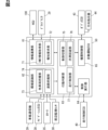
- FIG. 2 is a block diagram showing details of an autonomous driving ECU.
- FIG. 1 is a diagram showing an example of a scene in which a vehicle travels along a connecting road in a median strip.
- FIG. 13 is a diagram showing an example of a scene in which travel on a connecting road is avoided; 5 is a flowchart showing details of a congestion avoidance process according to the first embodiment.
- FIG. 11 is a diagram for explaining details of a Michigan-type intersection at which travel is expected in the second embodiment.
- FIG. 13 is a diagram showing an example of a scene in which travel on a diversion circuit is avoided.
- FIG. 1 is a diagram showing an overall view of an in-vehicle network including an autonomous driving ECU according to a first embodiment of the present disclosure.
- FIG. 2 is a block diagram showing details of an autonomous driving ECU.
- FIG. 11 is a diagram showing another example of a scene in which travel on a diversion circuit is avoided.
- FIG. 13 is a diagram showing yet another example of a scene in which travel on a diversion circuit is avoided.
- 10 is a flowchart showing details of a congestion avoidance process according to a second embodiment;
- FIG. 13 is a diagram showing an example of a scene in which traveling on a diversion circuit is avoided in the third embodiment.
- 13 is a flowchart showing details of a congestion avoidance process according to a third embodiment.
- FIG. 13 is a diagram showing an example of a scene in which a U-turn is made on a connecting road in the fourth embodiment.
- FIG. 11 is a diagram showing another example of a scene in which a U-turn is made on a connecting road.
- FIG. 1 is a diagram showing an example of a scene in which a U-turn or a left turn is made on a connecting road
- FIG. 1 is a diagram showing an example of a scene in which a U-turn is made from a traffic jam in a moving lane
- FIG. 11 is a diagram showing an example of a scene in which it is determined whether or not to avoid traveling on a connecting road.
- the function of the automatic driving control device is realized by an automatic driving ECU (Electronic Control Unit) 50 shown in Figures 1 and 2.
- the automatic driving ECU 50 is mounted on a vehicle (hereinafter, the host vehicle Am).
- the host vehicle Am By mounting the automatic driving ECU 50, the host vehicle Am becomes an automatic driving vehicle or an autonomous driving vehicle equipped with an automatic driving function, and is capable of running by the automatic driving function.
- the autonomous driving ECU 50 is an in-vehicle ECU that realizes an autonomous driving function that can take over driving operations from the driver.
- the autonomous driving ECU 50 can perform advanced driving assistance or partial autonomous driving of about level 2, and autonomous driving of level 3 or higher in which the system is the main controller.
- the autonomous driving levels in this disclosure are based on standards established by the Society of Automotive Engineers.
- Level 2 autonomous driving is autonomous driving with a surrounding monitoring obligation (eyes-on autonomous driving), which requires the driver to visually monitor the area around the vehicle.
- Level 2 autonomous driving includes hands-on autonomous driving, where the driver is required to hold the steering wheel, and hands-off autonomous driving, where the driver is not required to hold the steering wheel.
- Level 3 autonomous driving is eyes-off autonomous driving, which means that there is no need to monitor the area around the vehicle and no obligation to monitor the surroundings.
- the autonomous driving ECU 50 may be capable of Level 4 fully autonomous driving, in which the system performs all driving tasks under certain conditions, and Level 5 fully autonomous driving, in which the system performs all driving tasks under all conditions.
- Level 4 autonomous driving is brain-off autonomous driving, in which there is essentially no request for the driver to take over driving.
- Level 5 autonomous driving is driverless autonomous driving, which does not require a driver to be on board.
- the autonomous driving ECU 50 switches the control state of the autonomous driving function among multiple control states, including at least autonomous driving control with a surrounding monitoring obligation of Level 2 or lower, and autonomous driving control without a surrounding monitoring obligation of Level 3 or higher.
- autonomous driving control of Level 2 or lower will be referred to as “driving assistance control”
- autonomous driving control of Level 3 or higher will be referred to as “autonomous driving control.”
- the driver may be permitted to perform specific actions other than driving that have been prescribed in advance (hereinafter referred to as the second task).
- the driver is legally permitted to perform the second task until a request for a change of driving is made in cooperation between the HCU (Human Machine Interface Control Unit) 100 and the autonomous driving ECU 50 described below.
- HCU Human Machine Interface Control Unit
- the second task For example, actions such as watching entertainment content such as video content, operating devices such as a smartphone, and eating are envisioned as second tasks.
- the autonomous driving ECU 50 is communicatively connected to a communication bus 99 of an in-vehicle network 1 mounted on the host vehicle Am.
- a driver monitor 29, a surroundings monitoring sensor 30, a locator 35, a navigation ECU 38, an in-vehicle communication device 39, a driving control ECU 40, a body ECU 43, an HCU 100, and the like are connected to the communication bus 99.
- These nodes connected to the communication bus 99 are capable of communicating with each other.
- Certain nodes among these ECUs, etc. may be directly electrically connected to each other and capable of communicating with each other without going through the communication bus 99.
- the driver monitor 29 includes a near-infrared light source, a near-infrared camera, and a control unit that controls them.
- the driver monitor 29 is installed, for example, on the top surface of the steering column or the top surface of the instrument panel, with the near-infrared camera facing the headrest of the driver's seat.
- the driver monitor 29 uses the near-infrared camera to capture an image of the driver's head illuminated with near-infrared light from the near-infrared light source.
- the image captured by the near-infrared camera is analyzed by the control unit.
- the control unit extracts information such as the position and line of sight of the driver from the captured image.
- the driver monitor 29 provides the eye point position information and line of sight direction information extracted by the control unit to the HCU 100 and the autonomous driving ECU 50 as driver status information.
- the perimeter monitoring sensor 30 is an autonomous sensor that monitors the environment surrounding the host vehicle Am.
- the perimeter monitoring sensor 30 includes, for example, one or more of a camera unit 31, a millimeter wave radar 32, a lidar 33, and a sonar 34.
- the perimeter monitoring sensor 30 is capable of detecting moving objects and stationary objects within a detection range around the host vehicle.
- the perimeter monitoring sensor 30 provides detection information of objects around the host vehicle to the autonomous driving ECU 50, etc.
- the locator 35 includes a GNSS (Global Navigation Satellite System) receiver and an inertial sensor.
- the locator 35 combines positioning signals received from multiple positioning satellites by the GNSS receiver, the measurement results of the inertial sensor, and vehicle speed information output to the communication bus 99, and sequentially determines the position and traveling direction of the host vehicle Am.
- the locator 35 sequentially outputs position information and direction information of the host vehicle Am based on the positioning results to the communication bus 99 as locator information.
- the locator 35 further has a map database (hereinafter referred to as map DB) 36 that stores map data.
- the map DB 36 is mainly composed of a large-capacity storage medium that stores a large amount of three-dimensional map data and two-dimensional map data.
- the three-dimensional map data is a so-called HD (High Definition) map, and includes road information necessary for autonomous driving. Specifically, the three-dimensional map data includes three-dimensional shape information of roads and detailed information on each lane.
- the locator 35 can update the three-dimensional map data and two-dimensional map data to the latest information through external communication using the in-vehicle communication device 39.
- the locator 35 reads map data around the current position from the map DB 36, and provides it to the autonomous driving ECU 50, HCU 100, etc. together with locator information.
- the navigation ECU 38 acquires information about the destination specified by the driver or other passenger based on operation information acquired from the HCU 100.
- the navigation ECU 38 acquires vehicle position information and direction information from the locator 35, and sets a route from the current position to the destination.
- the navigation ECU 38 provides route information indicating the set route to the destination to the automatic driving ECU 50, HCU 100, etc.
- the navigation ECU 38 works in conjunction with the HMI system 10 to provide route guidance to the destination by combining screen displays and voice messages, etc., and notifying the driver of the direction of travel of the vehicle Am at intersections, branching points, etc.
- a user terminal such as a smartphone may be connected to the in-vehicle network 1 or the HCU 100.
- a user terminal may provide the autonomous driving ECU 50 with vehicle position information, direction information, map data, etc., in place of the locator 35.
- the user terminal may provide the autonomous driving ECU 50 and HCU 100 with route information to the destination in place of the navigation ECU 38.
- the in-vehicle communication device 39 is an external communication unit mounted on the vehicle Am, and functions as a V2X (Vehicle to Everything) communication device.
- the in-vehicle communication device 39 transmits and receives information via wireless communication between roadside devices installed on the side of the road and other vehicles around the vehicle.
- the in-vehicle communication device 39 receives congestion information and traffic regulation information around the current position of the vehicle Am and in the direction of travel from the roadside devices.
- the congestion information and traffic regulation information are, for example, VICS (registered trademark) information, etc.
- the on-board communication device 39 may be capable of receiving traffic light information indicating the lighting patterns of traffic lights installed at the intersection, as well as detection information of objects around the intersection, such as stopped vehicles, parked vehicles, pedestrians, and cyclists, from the roadside device and other vehicles.
- the on-board communication device 39 provides the received congestion information, traffic regulation information, traffic light information, detection information, etc. to the autonomous driving ECU 50 and HCU 100, etc.
- the driving control ECU 40 is an electronic control device that mainly includes a microcontroller.
- the driving control ECU 40 generates vehicle speed information indicating the current driving speed of the host vehicle Am based on the detection signals of wheel speed sensors installed in the hub portion of each wheel, and sequentially outputs the generated vehicle speed information to the communication bus 99.
- the driving control ECU 40 has at least the functions of a brake control ECU, a drive control ECU, and a steering control ECU.
- the driving control ECU 40 continuously performs braking force control for each wheel, output control of the on-board power source, and steering angle control based on operation commands based on the driver's driving operation or control commands from the automatic driving ECU 50.
- the body ECU 43 is an electronic control device that mainly includes a microcontroller.
- the body ECU 43 has at least the function of controlling the operation of lighting devices (e.g., turn indicators 44, etc.) mounted on the vehicle Am.
- lighting devices e.g., turn indicators 44, etc.
- the body ECU 43 Based on detection of a user operation input to a turn indicator switch provided on the steering column or the like, the body ECU 43 starts blinking either the left or right turn indicator 44 (blinker) corresponding to the operation direction.
- the body ECU 43 starts blinking either the left or right turn indicator 44 corresponding to the moving direction of the vehicle Am when changing lanes due to driving assistance control or autonomous driving control.
- the HCU 100 together with multiple display devices, an audio device 24, an ambient light 25, and an operating device 26, constitutes an HMI (Human Machine Interface) system 10.
- the HMI system 10 has an input interface function that accepts operations by an occupant, such as the driver, of the vehicle Am, and an output interface function that presents information to the driver.
- the display devices present information to the driver's vision through image display, etc.
- the display devices include a meter display 21, a center information display (hereafter, CID) 22, and a head-up display (hereafter, HUD) 23, etc.
- the CID 22 has a touch panel function and detects touch operations on the display screen by the driver, etc.
- the audio device 24 has multiple speakers installed in the vehicle cabin in an arrangement surrounding the driver's seat, and reproduces notification sounds, voice messages, etc. through the speakers into the vehicle cabin.
- the ambient lights 25 are provided on the instrument panel, steering wheel, etc. The ambient lights 25 present information to the driver using his peripheral vision through an ambient display that changes the color of the light emitted.
- the operation device 26 is an input unit that accepts user operations by the driver, etc. User operations related to starting and stopping the autonomous driving function, and user operations related to setting a destination for route guidance, etc. are input to the operation device 26.
- the operation device 26 includes a steering switch provided on the spokes of the steering wheel, an operation lever provided on the steering column, and a voice input device that recognizes the contents of the driver's speech, etc.
- the HCU 100 is a computer that mainly includes a processing unit 11, a RAM 12, a storage unit 13, an input/output interface 14, and a control circuit equipped with a bus connecting these.
- the HCU 100 functions as a presentation control device, and comprehensively controls the presentation of information using multiple display devices, an audio device 24, and an ambient light 25.
- the HCU 100 presents information related to autonomous driving in cooperation with the autonomous driving ECU 50.
- the HCU 100 acquires control status information indicating the operating state of the autonomous driving function, and a request to present information related to the autonomous driving function from the autonomous driving ECU 50.
- the HCU 100 provides content and presents information in accordance with the operating state of the autonomous driving, based on the control status information and the implementation request. For example, when the autonomous driving ECU 50 plans to end autonomous driving control, the HCU 100 issues a notification requesting the implementation of a driving operation, in other words, a notification requesting a change of driving.
- the HCU 100 acquires operation information indicating the content of user operations from the CID 22, the operation device 26, etc.
- the HCU 100 provides operation information of user operations related to the autonomous driving function to the autonomous driving ECU 50.
- the HCU 100 provides operation information of user operations for setting the destination of the host vehicle Am to the navigation ECU 38.
- the autonomous driving ECU 50 is a computer that mainly includes a processing unit 51, a RAM 52, a storage unit 53, an input/output interface 54, and a control circuit including a bus connecting these units.
- the processing unit 51 executes various processes (instructions) for realizing the autonomous driving control method of the present disclosure by accessing the RAM 52.
- the storage unit 53 stores various programs (autonomous driving control programs, etc.) executed by the processing unit 51.
- the autonomous driving ECU 50 is configured with an information linking unit 61, an environment recognition unit 62, an action determination unit 63, a control execution unit 64, an equipment control unit 65, etc. as multiple functional units for realizing the autonomous driving function (see FIG. 2).
- the information linking unit 61 provides information to the HCU 100 and acquires information from the HCU 100 and the driver monitor 29.
- the information linking unit 61 acquires control state information indicating the operating state of the autonomous driving function from the action determination unit 63, and provides the acquired control state information to the HCU 100.
- the control state information includes information indicating the autonomous driving level of the autonomous driving function in the operating state.
- the information linking unit 61 has an HMI information acquisition unit 71 and a notification request unit 72 as sub-functional units for information linking with the HCU 100 and the driver monitor 29.
- the HMI information acquisition unit 71 grasps the contents of user operations input to the CID 22 and the operation device 26 by the driver, etc., based on the operation information acquired from the HCU 100.
- the HMI information acquisition unit 71 grasps, for example, a level 2 transition operation that instructs a transition from manual driving to driving assistance control, and a level 3 transition operation that instructs a transition from driving assistance control to autonomous driving control.
- the HMI information acquisition unit 71 grasps the driver's behavior based on the driver status information acquired from the driver monitor 29.
- the HMI information acquisition unit 71 continuously grasps the driver's driving posture, line of sight direction, whether surrounding monitoring is being performed, whether a second task is being performed, and the degree of alertness, etc.
- the notification request unit 72 enables the HCU 100 to issue a notification synchronized with the operating state of the autonomous driving function by outputting a request to the HCU 100 to issue a notification. For example, when the autonomous driving control is scheduled to end, the notification request unit 72 outputs a request to the HCU 100 to issue a notification requesting a change of driving. The notification request unit 72 outputs a request to the HCU 100 to issue a notification related to congestion avoidance control, which will be described later. Based on the notification request obtained from the notification request unit 72, the HCU 100 issues a notification that appropriately combines a virtual image or screen display by the display device, a notification sound or message played by the audio device 24, and an ambient display by the ambient light 25, etc.
- the environment recognition unit 62 recognizes the driving environment of the host vehicle Am by combining the locator information and map data obtained from the locator 35 with the detection information obtained from the surrounding monitoring sensor 30.
- the environment recognition unit 62 can use the detection information received by the in-vehicle communication device 39 to recognize the driving environment.
- the environment recognition unit 62 obtains route information from the navigation ECU 38 and provides the obtained route information to the action determination unit 63.
- the environment recognition unit 62 obtains vehicle speed information indicating the current driving speed from the communication bus 99 as information indicating the state of the host vehicle Am.
- the environment recognition unit 62 has an other vehicle recognition unit 73 and a road recognition unit 74 as sub-functional units for recognizing the driving environment.
- the other vehicle grasping unit 73 grasps the relative position and relative speed of dynamic targets around the vehicle, such as other vehicles traveling around the vehicle Am. As an example, when a lane change is performed due to driving assistance control or autonomous driving control, the other vehicle grasping unit 73 grasps the relative position and relative speed of other vehicles traveling in an adjacent lane, and determines whether there is space in the adjacent lane in which the vehicle Am can move.
- the road understanding unit 74 acquires information related to the road on which the host vehicle Am is traveling or is scheduled to travel. Specifically, when the host vehicle Am is traveling on a road including multiple lanes, the road understanding unit 74 identifies the position of the host vehicle lane in which the host vehicle Am is traveling. In addition, the road understanding unit 74 acquires route information from the navigation ECU 38, and identifies which of the multiple lanes the host vehicle Am should travel in.
- the road identification unit 74 identifies whether the road on which the vehicle Am is traveling or is scheduled to travel is within a preset permitted area. In permitted areas, autonomous driving control of level 3 or higher is permitted. The conditions for whether or not the area is within a permitted area correspond to the road conditions in the operational design domain.
- the operational design domain is a specific condition related to the designed driving environment that is the premise for the autonomous driving ECU 50 to operate normally, and is set according to the capabilities of the autonomous driving ECU 50.
- Information indicating whether or not the area is within a permitted area may be recorded in the map data stored in the map DB 36, or may be included in the received information received by the on-board communication device 39. For example, expressways, motorways, and specific general roads that have been developed to enable autonomous driving are set as permitted areas.
- the behavior determination unit 63 When the autonomous driving ECU 50 has control of driving operations, the behavior determination unit 63 generates a planned driving line for the host vehicle Am to travel on, based on the results of the recognition of the driving environment by the environment recognition unit 62 and the route information generated by the navigation ECU 38. The behavior determination unit 63 outputs the generated planned driving line to the control execution unit 64.
- the behavior determination unit 63 has a control switching unit 75 as a sub-functional unit for controlling the operating state of the autonomous driving function.
- the control switching unit 75 cooperates with the HCU 100 to control the switching of driving between the autonomous driving ECU 50 and the driver.
- the control switching unit 75 switches between level 2 driving assistance control, in which the driver is obligated to monitor the surroundings, and level 3 or higher autonomous driving control, in which the driver is not obligated to monitor the surroundings.
- the control switching unit 75 permits the implementation of level 3 or higher autonomous driving on roads within the permitted area, and permits only level 2 autonomous driving on roads outside the permitted area. Furthermore, the control switching unit 75 switches between level 3 autonomous driving and level 4 or level 5 autonomous driving, among the autonomous driving controls in which there is no obligation to monitor the surroundings.
- the control switching unit 75 generates control status information indicating the current operating status of the autonomous driving function, and provides the generated control status information to the information linking unit 61, etc.
- control execution unit 64 cooperates with the cruise control ECU 40 to execute acceleration/deceleration control and steering control of the host vehicle Am according to the planned driving line generated by the action determination unit 63. Specifically, the control execution unit 64 generates control commands based on the planned driving line and sequentially outputs the generated control commands to the cruise control ECU 40.
- the device control unit 65 controls the start and end of the blinking operation of the direction indicator 44 by outputting a control command to the body ECU 43. During a period of travel under driving assistance control or autonomous driving control, the device control unit 65 causes the blinking operation of the direction indicator 44 on the moving side to be performed in accordance with a lane change, U-turn, right or left turn, etc., of the host vehicle Am (see FIG. 3, etc.).
- the median strip MB is provided in a strip between two lanes (or groups of lanes) that travel in opposing directions.
- the median strip MB separates the roadway into two directions.
- the median strip MB may separate the two lanes only by structures such as fences, plastic poles, curbs, and wire ropes, or it may include an area with plantings, etc.
- the median strip MB may also be provided with structures such as pillars that support an elevated road.
- the connecting road CL is a driving area that connects two lanes that are separated by a median strip MB according to direction.
- an opening in the median strip MB (hereinafter, median strip opening MO), in other words, a gap or other part of the median strip MB, is considered to be the connecting road CL.
- the connecting road CL may be part of an intersection IS.
- a main road with a median strip MB intersects with a community road (cross road R3) that connects to this main road.
- the intersection IS may be equipped with traffic lights.
- the intersection IS may be a T-junction or a crossroads.
- the automatic driving ECU 50 drives the vehicle Am along the connecting road CL (see FIG. 3).
- the automatic driving ECU 50 drives the vehicle Am along the connecting road CL while maintaining the driving assistance control of level 2 (hands-off) in which the driver is obligated to monitor the surroundings, or the autonomous driving control of level 3 or higher in which the driver is not obligated to monitor the surroundings.
- the vehicle Am can make a U-turn from the lane of the road on which it is traveling (hereinafter, the traveling lane R1) to the lane of the opposing road (hereinafter, the merging lane R2), or a left turn (or right turn) from the cross road R3 to the merging lane R2.
- the traveling lane R1 the traveling lane facing the center divider MB
- the inside lane facing the median strip MB is usually the merging lane R2 that you will merge into immediately after making a U-turn.
- the autonomous driving ECU 50 performs congestion avoidance control to avoid congestion and the occurrence of congestion when making a U-turn from the driving lane R1 to the merging lane R2 across the median MB, or when entering the merging lane R2 from the intersecting road R3 across the median MB.
- the congestion avoidance control is realized by cooperation between the environment recognition unit 62 and the behavior determination unit 63.
- the environment recognition unit 62 refers to the route information acquired from the navigation ECU 38 and determines whether the planned driving route of the vehicle Am has been set to a connecting road CL. When the planned driving route of the vehicle Am has been set to a connecting road CL, the environment recognition unit 62 acquires road information related to this connecting road CL. The environment recognition unit 62 determines whether the connecting road CL on which the planned driving route has been set is an intersection IS. When the connecting road CL is an intersection IS, the environment recognition unit 62 determines whether a traffic light is installed at this intersection IS.
- the environment recognition unit 62 acquires road information of the merging lane R2 located beyond the connecting road CL. Specifically, the environment recognition unit 62 acquires congestion information indicating whether the merging lane R2 is congested (congested), i.e., the above-mentioned VICS information and V2X information received by the in-vehicle communication device 39. The environment recognition unit 62 may determine whether the merging lane R2 is congested using image data of the merging lane R2 captured by the camera unit 31 during the period when the vehicle is traveling on the lane R1 toward the connecting road CL. The environment recognition unit 62 may determine whether the merging lane R2 is congested using point cloud data generated by detection by the Lidar 33 instead of or together with the image data.
- the environment recognition unit 62 further acquires information on the detour DL, which is the next connecting road CL after the connecting road CL for which the planned driving route is set, by a search request to the navigation ECU 38.
- the environment recognition unit 62 determines whether the detour DL is within a predetermined distance (e.g., about 1 km) from the first connecting road CL or the current position of the vehicle Am.
- the predetermined distance may be changeable by the user of the vehicle Am, or may be changed appropriately depending on the degree of congestion occurring in the merging lane R2. If the vehicle Am is unable to travel on the connecting road CL for which the planned driving route is set initially, the vehicle Am travels on the detour DL and moves from the traveling lane R1 to the merging lane R2.
- the behavior determination unit 63 has a driving control unit 77 and a congestion avoidance unit 76 as sub-functional units.
- the driving control unit 77 controls the U-turn driving of the host vehicle Am passing through the connecting road CL and heading from the current lane R1 to the merging lane R2.
- the congestion avoidance unit 76 estimates whether the host vehicle Am will be caught in congestion caused by the connecting road CL based on the road information acquired by the environment recognition unit 62. When it is estimated that the host vehicle Am will be caught in congestion caused by the connecting road CL, the congestion avoidance unit 76 avoids driving on the nearest connecting road CL.
- the congestion avoidance unit 76 avoids traveling on this connecting road CL (intersection IS). As a result, the vehicle Am does not make a U-turn or turn right or left across the median MB at the intersection IS without a traffic light.
- the congestion avoidance unit 76 makes the vehicle Am turn right once.
- the congestion avoidance unit 76 makes the driving control unit 77 make a U-turn of the vehicle Am using the intersection IS with a traffic light or the next median opening MO as the detour route DL (see Figure 4).
- the congestion avoidance unit 76 avoids traveling on the connecting road CL when congestion is estimated on the merging lane R2 based on the road information of the merging lane R2. As a result, if the vehicle Am is forced to stop in front of the center median MB due to road conditions on the merging lane R2, it will not make a U-turn or turn right or left there.
- the congestion avoidance unit 76 causes the driving control unit 77 to make a U-turn or turn right or left of the vehicle Am using an uncongested intersection IS or the next median opening MO as the detour route DL (see Figure 4).
- the congestion avoidance unit 76 determines whether there is a detour DL, which is the next connecting road CL after the nearest connecting road CL. If there is no intersection IS or median opening MO that becomes a detour DL after the nearest connecting road CL, or if the detour DL is more than a predetermined distance away from the nearest connecting road CL or the current position, the congestion avoidance unit 76 decides to travel on the nearest connecting road CL. In this case, even if there is no traffic light at the intersection IS or the merging lane R2 is congested, the congestion avoidance unit 76 decides to perform a U-turn or a right or left turn by traveling on the nearest connecting road CL.
- the avoidance determination process is started by the automatic driving ECU 50 on the condition that the planned driving route of the host vehicle Am is set to the connecting road CL and the host vehicle Am has approached this connecting road CL to within a predetermined distance (for example, about 1 km).
- the environment recognition unit 62 cooperates with the navigation ECU 38 to obtain detour information regarding the detour DL. Based on the detour information obtained in S11, the environment recognition unit 62 determines in S12 whether or not a detour DL exists within a predetermined distance. If it is determined that a detour DL does not exist within the predetermined distance (S12: NO), the congestion avoidance unit 76 determines in S17 to travel on the nearest connecting road CL.
- the environment recognition unit 62 acquires road information related to the connecting road CL in S13. Based on the road information acquired in S13, the environment recognition unit 62 determines whether or not a connecting road CL is set at the intersection IS in S14. If a connecting road CL is set at the intersection IS (S14: YES), the environment recognition unit 62 determines whether or not a traffic signal is installed at the intersection IS based on the road information in S15. If a traffic signal is installed at the intersection IS (S15: YES), the congestion avoidance unit 76 determines to travel through the intersection IS as the connecting road CL in S17.
- the environment recognition unit 62 estimates the road conditions of the merging lane R2 based on the road information in S16. Specifically, the environment recognition unit 62 estimates whether the merging lane R2 is congested. If it is estimated that the merging lane R2 is not congested (S16: NO), the congestion avoidance unit 76 determines in S17 to travel on the nearest connecting road CL (see FIG. 3). On the other hand, if it is estimated that the merging lane R2 is congested (S16: YES), the congestion avoidance unit 76 determines in S18 to avoid traveling on the nearest connecting road CL.
- the congestion avoidance unit 76 does not direct the host vehicle Am to the connecting road CL, but continues traveling on the current lane R1.
- the vehicle Am travels along the detour DL and makes a U-turn from the current lane R1 to the merging lane R2 (see Figure 4).
- the congestion avoidance unit 76 avoids driving on the connecting road CL when congestion is estimated on the merging lane R2. This control prevents the host vehicle Am from getting caught in congestion at the intersection IS without traffic lights. As a result, the convenience of automated driving is less likely to be compromised in situations where it is necessary to cross the center median strip MB.
- the congestion avoidance unit 76 avoids driving through the intersection IS that is set as a connecting road CL.
- the host vehicle Am will not be stuck at an intersection IS that does not have a traffic signal.
- the convenience of automated driving is less likely to be compromised in situations where it is necessary to cross the median strip MB.
- information on the detour route DL which is the next connecting route CL after the connecting route CL for which the planned driving route is set, is further acquired. Then, if the detour route DL does not exist within a predetermined distance, the congestion avoidance unit 76 decides to drive on the nearest connecting route CL. As a result, it becomes less likely that a significant delay in arrival time will occur due to not driving on the nearest connecting route CL. As a result, the convenience of automated driving can be further ensured.
- the central reservation strip MB corresponds to the "reservoir strip”
- the environment recognition unit 62 corresponds to the "information acquisition unit”
- the automatic driving ECU 50 corresponds to the "automatic driving control device”.
- the second embodiment of the present disclosure is a modified example of the first embodiment.
- the autonomous driving ECU 50 according to the second embodiment drives the host vehicle Am according to the Michigan intersection ML while maintaining the driving assistance control of level 2 in which the driver is required to monitor the surroundings, or the autonomous driving control of level 3 or higher in which the driver is not required to monitor the surroundings.
- a Michigan-type intersection ML is an at-grade intersection where vehicles turning left are handled by a combination of right turns and U-turns, based on the standard of keeping to the right. Left turns are prohibited at a Michigan-type intersection ML (see dashed line in Figure 6).
- the main road RM At a Michigan-type intersection ML, at least one of the two intersecting roads (hereinafter, the main road RM) has a median strip MB.
- the main road RM has a median strip MB.
- a Michigan-type intersection ML also includes a turnaround UL for crossing the median strip MB and making a U-turn.
- the turnaround UL corresponds to the connecting road CL in the first embodiment, and connects the traveling lane R1 and the merging lane R2, which are separated by the median strip MB according to direction.
- a vehicle that wants to turn left must turn around via the turnaround UL, and then make a right turn or the like in the at-grade intersection area IA that it re-enters.
- the autonomous driving ECU 50 wants to turn the vehicle Am left from the main road RM onto the crossroad R3, it moves the vehicle Am to the entry section AL for entering the turning lane UL (see FIG. 6).
- the vehicle Am travels through the entry section AL and goes straight through the at-grade intersection area IA of the Michigan intersection ML.
- the vehicle Am reverses its direction of travel by merging into the merging lane R2.
- the vehicle Am can move to the right-turn lane Lrt by changing lanes in the merging lane R2 and proceed to the crossroad R3 on the left turn side from the original vehicle position by making a right turn in the at-grade intersection area IA.
- the autonomous driving ECU 50 when the autonomous driving ECU 50 wants to turn the host vehicle Am left from the intersecting road R3 onto the main road RM, it causes the host vehicle Am to enter the entry section AL by turning right at the at-grade intersection area IA. After entering the turning lane UL, the host vehicle Am reverses its direction of travel by merging into the merging lane R2 and continues straight through the at-grade intersection area IA. As a result, the host vehicle Am can proceed onto the main road RM on the left turn side as viewed from the original vehicle position.
- the autonomous driving ECU 50 performs congestion avoidance control to avoid congestion and the occurrence of congestion when the host vehicle Am travels on the turning path UL of the Michigan intersection ML while continuing the driving assistance control or the autonomous driving control.
- the congestion avoidance control of the second embodiment is also realized by cooperation between the environment recognition unit 62 and the congestion avoidance unit 76, as in the first embodiment. Details of the congestion avoidance control performed by the autonomous driving ECU 50 will be described below based on Figures 7 to 9 and with reference to Figures 1 and 2.
- the environment recognition unit 62 refers to the route information acquired from the navigation ECU 38 and determines whether the planned driving route of the vehicle Am is set to a turning route UL. When a planned driving route is set with a turning route UL as a connecting road CL, the environment recognition unit 62 acquires road information related to the Michigan intersection ML that includes the turning route UL.
- the environment recognition unit 62 acquires, as road information, congestion information indicating whether the turning lane UL, the entry section AL for entering the turning lane UL, and the merging lane R2 located beyond the turning lane UL are congested (congested). In addition, the environment recognition unit 62 acquires, as road information, the number of lanes in the merging lane R2, and determines the number of lane changes required to move to the right-turn lane Lrt (see FIG. 9).
- the environment recognition unit 62 obtains information on the detour DL, which is the next connecting road CL of the turning road UL for which the planned driving route is set, by a search request to the navigation ECU 38.
- the environment recognition unit 62 determines whether the detour DL is within a predetermined distance from the nearest turning road UL or the current position of the vehicle Am.
- the detour DL may be the turning road UL of the next Michigan intersection ML, or may be a median opening MO (see FIG. 3) provided in the center median MB, etc. If the vehicle Am is initially unable to travel on the UL for which the planned driving route is set, it can turn back from the current lane R1 to the merging lane R2 by traveling on the detour DL.
- the congestion avoidance unit 76 determines whether the host vehicle Am will be caught in a congestion caused by a Michigan intersection ML based on the road information acquired by the environment recognition unit 62. When it is estimated that the host vehicle Am will be caught in a congestion caused by a Michigan intersection ML, the congestion avoidance unit 76 causes the planned driving route to avoid driving on the connecting road CL.
- the congestion avoidance unit 76 avoids driving on the turning route UL when congestion (congestion) on the turning route UL or the entry section AL is estimated based on the road information of the turning route UL and the entry section AL (see FIG. 7).
- the congestion avoidance unit 76 stops changing lanes to the entry section AL and causes the driving control unit 77 to continue driving on the current driving lane R1.
- the congestion avoidance unit 76 cooperates with the driving control unit 77 to turn the host vehicle Am right into the driving lane of the main road RM excluding the entry section AL.
- stopping on the turning route UL or stopping to wait for a right turn to enter the entry section AL is avoided, and the host vehicle Am drives to the next turning route UL (detour DL).
- the congestion avoidance unit 76 avoids driving on the turning lane UL when congestion (traffic jam) on the merging lane R2 is estimated based on the road information of the merging lane R2 (see FIG. 8).
- the congestion avoidance unit 76 does not change lanes from the current lane R1 to the approach section AL, and causes the driving control unit 77 to continue driving on the current lane R1.
- congestion occurs on the merging lane R2 to which the vehicle Am is scheduled to move after passing the turning lane UL and the vehicle Am cannot immediately merge into the merging lane R2
- the vehicle Am will not turn back on the nearest turning lane UL and will drive to the next turning lane UL (detour DL).
- the congestion avoidance unit 76 refers to the planned driving route grasped by the environment recognition unit 62, and when a planned driving route is set in which a right turn is made within a predetermined distance (e.g., about 300 m) after merging from the turning route UL to the merging lane R2, the traffic jam avoidance unit 76 avoids driving on the turning route UL (see FIG. 9). That is, if there is a side road R4 onto which the vehicle wants to turn right immediately after merging, it is decided to avoid driving on the turning route UL. In this case, the vehicle Am travels straight on the current lane R1, and then travels to the next turning route UL (detour route DL). The vehicle Am turns back from the current lane R1 to the merging lane R2 on the detour route DL, travels on the merging lane R2 for a predetermined distance or more, and then makes a right turn onto the side road R4.
- a predetermined distance e.g., about 300 m
- the congestion avoidance unit 76 avoids driving on the turn circuit UL when a planned driving route is set to make a right turn at the first intersection area (level intersection area IA) in the merging lane R2 and a predetermined number of lane changes are required to move to the right-turn lane Lrt (see FIG. 9). That is, when the merging lane R2 is a predetermined number or more, it is determined to avoid driving on the turn circuit UL.
- the congestion avoidance unit 76 may avoid turning back on the nearest turn circuit UL when two or more lane changes are required to cross two merging lanes R2, or may avoid turning back on the nearest turn circuit UL when three or more lane changes are required to cross three merging lanes R2.
- the host vehicle Am travels straight on the current lane R1 and then travels to the next turn circuit UL (detour DL).
- the vehicle Am turns around from the driving lane R1 to the merging lane R2 on the detour DL, makes multiple lane changes with ample time, and turns right from the right-turn lane Lrt onto the intersecting road R3.
- the congestion avoidance unit 76 determines whether there is a detour DL, which is the next connecting road CL of the most recent turning road UL. If there is no detour DL within a predetermined distance, the congestion avoidance unit 76 decides to travel on the most recent turning road UL. For example, if the most recent turning road UL is the last connecting road CL on the main road RM, or if the detour DL is a predetermined distance or more away from the most recent turning road UL or the current position, the congestion avoidance unit 76 decides to travel on the most recent connecting road CL.
- the congestion avoidance unit 76 decides to make a U-turn by traveling on the most recent turning road UL even if any of the turning road UL, the entry section AL, and the merging lane R2 is congested, or if there is a right turn or a predetermined number of lane changes immediately after merging.
- the avoidance determination process of the second embodiment is started by the automatic driving ECU 50 on the condition that the planned driving route of the host vehicle Am is set to the turning course UL of the Michigan type intersection ML and the host vehicle Am has approached the Michigan type intersection ML within a predetermined distance (for example, about 1 km).
- the environment recognition unit 62 cooperates with the navigation ECU 38 to obtain detour information regarding the detour DL. Based on the detour information obtained in S21, the environment recognition unit 62 determines in S22 whether or not a detour DL exists within a predetermined distance. If no detour DL exists within the predetermined distance (S22: NO), the congestion avoidance unit 76 determines in S29 to travel on the nearest turning route UL.
- the environment recognition unit 62 acquires road information related to the Michigan intersection ML in S23. Furthermore, the environment recognition unit 62 determines in S24 whether a planned driving route is set that includes a right turn immediately after merging from the turning lane UL to the merging destination lane R2. If a right turn onto side road R4 is planned immediately after merging (S24: YES), the congestion avoidance unit 76 determines in S28 to avoid driving on the nearest connecting road CL (see FIG. 9).
- the environment recognition unit 62 determines in S25 whether a right turn is planned in the at-grade intersection area IA. In addition, if a right turn is planned in the at-grade intersection area IA, the environment recognition unit 62 determines whether a predetermined number (multiple times) or more of lane changes (indicated as LC in FIG. 10) are required to move to the right-turn lane Lrt.
- the congestion avoidance unit 76 determines in S28 to avoid driving on the nearest connecting road CL (see FIG. 9).
- the environment recognition unit 62 grasps the congestion status of the turning lane UL, etc. based on the road information in S26. If it is estimated that the turning lane UL or the entry section AL is congested (S26: YES), the congestion avoidance unit 76 decides to avoid driving on the nearest connecting road CL in S28 (see FIG. 7).
- the environment recognition unit 62 further estimates whether or not the merging lane R2 is congested based on the road information in S27. If the merging lane R2 is not congested (S27: NO), the congestion avoidance unit 76 decides to travel on the nearest turning lane UL in S29. On the other hand, if the merging lane R2 is congested (S27: YES), the congestion avoidance unit 76 decides to avoid traveling on the nearest connecting road CL in S28 (see FIG. 8).
- the second embodiment described so far also has the same effect as the first embodiment, and when it is estimated that the vehicle Am will be caught in a traffic jam caused by a connecting road CL set in the planned travel route, the vehicle Am avoids traveling on the connecting road CL, and as a result, it is possible to avoid a traffic jam on the route crossing the central reservation strip MB.
- the congestion avoidance unit 76 avoids driving on the turning circuit UL. As a result, even at a Michigan-type intersection ML that requires passing through a turning circuit UL, congestion on the route crossing the center reservation strip MB can be avoided.
- road information is acquired for the turning course UL or the approach section AL for entering the turning course UL.
- the congestion avoidance unit 76 avoids traveling on the turning course UL when congestion is estimated to be present on the turning course UL or the approach section AL based on the road information.
- This control makes it difficult for the host vehicle Am to become caught up in congestion on the turning course UL or the approach section AL.
- the convenience of automated driving can be ensured even when it is necessary to cross the center divider MB at a Michigan intersection ML.
- road information for the merging lane R2 located beyond the turning lane UL is acquired. Then, based on the road information for the merging lane R2, the congestion avoidance unit 76 avoids traveling on the turning lane UL when congestion on the merging lane R2 is estimated. This type of control makes it difficult for the host vehicle Am to become stuck on the turning lane UL. Therefore, congestion on the route that crosses the central reservation strip MB can be avoided.
- the congestion avoidance unit 76 avoids driving on the turning road UL.
- This control makes it difficult to smoothly turn right immediately after merging, disrupting traffic on the merging lane R2, or forcing a detour. As a result, a decrease in the convenience of automated driving can be more reliably avoided.
- the number of lanes in the merging lane R2 is acquired as road information. If a planned driving route is set that involves a right turn at the first grade intersection area IA in the merging lane R2 and a predetermined number of lane changes are required to move to the right-turn lane Lrt, the congestion avoidance unit 76 avoids driving on the diversion circuit UL. This control makes it less likely that a lane change immediately after merging will be unable to be performed smoothly, disrupting traffic on the merging lane R2, or making it impossible to turn right. As a result, a deterioration in the convenience of automated driving can be more reliably avoided.
- the congestion avoidance unit 76 decides to drive on the nearest turning road UL. As a result, it becomes less likely that a significant delay in arrival time will occur due to not driving on the nearest turning road UL. As a result, it is possible to more reliably avoid a deterioration in the convenience of automated driving.
- the at-grade intersection area IA corresponds to the "intersection area”.
- the third embodiment of the present disclosure is a modified example of the second embodiment.
- a part of the congestion avoidance processing (see FIG. 12) is different from that of the second embodiment. Details of the congestion avoidance processing of the third embodiment will be described below based on FIG. 11 and FIG. 12, and with reference to FIG. 1 and FIG. 2. Note that steps S42 to S44, S47, and S50 of the congestion avoidance processing of the third embodiment are substantially the same as steps S24 to S26, S28, and S29 of the second embodiment.
- the environment recognition unit 62 further acquires traffic light information indicating the lighting pattern of the traffic lights TL (see FIG. 11) installed in the at-grade crossing area IA of the Michigan intersection ML as road information related to the Michigan intersection ML (S41).
- the environment recognition unit 62 acquires at least the traffic light information of the traffic light TL that is first encountered after merging into the merging lane R2.
- the traffic light information may be information recognized by the forward camera unit 31 when passing through the first at-grade crossing area IA, or may be information received by the vehicle-mounted communication unit 39 from a roadside unit or another vehicle.
- the congestion avoidance unit 76 avoids driving on the diversion path UL when congestion (traffic jam) is estimated on the merging lane R2 based on the traffic light information of the traffic light TL and the road information of the merging lane R2 (see FIG. 11). More specifically, the congestion avoidance unit 76 determines whether the traffic light TL is in a lighting pattern (red light) instructing a stop (S45). If the traffic light TL is red (S45: YES), the congestion avoidance unit 76 determines whether the merging lane R2 is congested (S46).
- the congestion avoidance unit 76 determines to avoid driving on the turning lane UL (S47). In this case, the congestion avoidance unit 76 causes the host vehicle Am (driving control unit 77) to continue driving on the current lane R1 without changing lanes from the current lane R1 to the entry section AL.
- the congestion avoidance unit 76 decides to drive on the nearest turning lane UL (S50). In addition, if the traffic light TL is in a lighting pattern (green light) that allows the vehicle to proceed (S45: NO), the congestion avoidance unit 76 decides to drive on the nearest turning lane UL (S50), regardless of whether the merging lane R2 is congested or not. In these cases, the congestion avoidance unit 76 changes lanes of the vehicle Am from the current lane R1 to the entry section AL.
- the environment recognition unit 62 obtains information on the detour route DL, which is the next connecting road CL, by a search request to the navigation ECU 38 (S48).
- the congestion avoidance unit 76 determines whether the detour route DL is present within a predetermined distance (S49). If the congestion avoidance unit 76 does not know the detour route DL within the predetermined distance (S49: NO), it cancels the decision to avoid traveling on the turn route UL and decides to travel on the nearest turn route UL (S50). On the other hand, if the detour route DL is present within the predetermined distance (S49: YES), the congestion avoidance unit 76 maintains the decision to avoid traveling on the turn route UL.
- the third embodiment described so far also has the same effect as the second embodiment, and when it is estimated that the vehicle Am will be caught in a traffic jam caused by the Michigan intersection ML, it is determined to avoid traveling through the turning circuit UL. As a result, even at the Michigan intersection ML where it is necessary to pass through the turning circuit UL, it is possible to avoid a traffic jam on the route crossing the center reservation strip MB.
- the road information includes congestion information indicating whether the merging lane R2 is congested and traffic light information indicating the lighting pattern of the first traffic light TL after merging into the merging lane R2.
- the traffic jam avoidance unit 76 avoids driving on the turning path UL when the traffic light TL is in a lighting pattern that indicates a stop and the merging lane R2 is congested. This control makes it difficult for the host vehicle Am to stagnate on the turning path UL.
- the traffic jam avoidance unit 76 determines to drive on the turning path UL. This allows the vehicle to quickly turn back from the traveling lane R1 to the merging lane R2, making it easier to ensure the convenience of automatic driving.
- the congestion avoidance unit 76 when the congestion avoidance unit 76 decides to avoid traveling on the turning route UL, information on the detour route DL, which is the next connecting route CL, is further acquired. Then, when the detour route DL does not exist within a predetermined distance, the congestion avoidance unit 76 cancels the decision to avoid traveling on the turning route UL. Even with this control, it becomes difficult for a significant delay in arrival time to occur due to not traveling on the nearest turning route UL. As a result, a deterioration in the convenience of automated driving can be avoided.
- the second embodiment of the present disclosure is a modified example of the first embodiment.
- the autonomous driving ECU 50 performs a U-turn driving through the connecting path CL of the median strip opening MO while continuing the driving assistance control or the autonomous driving control. Details of the U-turn driving control performed in scenes 1 to 5 will be described below based on Figures 13 to 17 and with reference to Figures 1 and 2.
- the environment recognition unit 62 acquires information indicating a right or left turn-compatible lane Lng among the multiple merging lanes R2 that corresponds to the planned right or left turn. Specifically, when a right turn is planned within a predetermined distance after moving to the merging lane R2, the environment recognition unit 62 sets the oncoming outer lane Lco among the multiple merging lanes R2 as the right or left turn-compatible lane Lng.
- the environment recognition unit 62 sets the oncoming inner lane Lci among the multiple merging lanes R2 as the right or left turn-compatible lane Lng.
- the driving control unit 77 changes the manner of U-turn driving from the connecting road CL to the right/left turn lane Lng depending on the position of the right/left turn lane Lng among the multiple merging lanes R2.
- the driving control unit 77 generates an inner loop driving line PLi that makes a small turn from the current lane R1 that borders the center divider MB to the oncoming inside lane Lci.
- the driving control unit 77 when the oncoming outside lane Lco is a right/left turn lane Lng, the driving control unit 77 generates an outer loop driving line PLo that makes a large turn from the current lane R1 that faces the center divider MB to the oncoming outside lane Lco.
- the host vehicle Am performs a U-turn driving on the connecting road CL of the median strip opening MO according to the inner loop driving line PLi or the outer loop driving line PLo.
- the outer driving line PLo may be generated so that the host vehicle Am approaches close to the outer road edge RE.
- the driving control unit 77 changes the steering angle (tire angle) of the host vehicle Am when temporarily stopping on the connecting road CL (see dashed line in FIG. 13) depending on the position of the merging lane R2 (right/left turn lane Lng) into which the host vehicle Am will enter by making a U-turn among multiple merging lanes R2.
- the driving control unit 77 makes the steering angle at the temporary stop accompanying the U-turn larger than when entering the oncoming outside lane Lco.
- the steering wheels of the host vehicle Am when temporarily stopping are set closer to being straight than when entering the oncoming inside lane Lci by making a small turn.
- the notification request unit 72 cooperates with the HMI system 10 to notify the driver of the planned U-turn and subsequent right or left turns.
- the notification request unit 72 notifies the driver of the planned U-turn and right or left turns, which are consecutive branches, all at once.
- Information indicating the U-turn and information indicating the right or left turn are presented to the driver at once by screen display by the meter display 21 and CID 22, or virtual image display by the HUD 23.
- the notification of the planned U-turn is emphasized more than the notification of the planned right or left turn thereafter. As an example, the image indicating the planned U-turn is displayed larger than the image indicating the planned right or left turn.
- the driving control unit 77 suppresses the acceleration of the host vehicle Am more than when there is no preceding vehicle.
- the driving control unit 77 can prevent the host vehicle Am from approaching too close to a preceding vehicle that has suddenly decelerated to make a U-turn when passing through a connecting road CL where a U-turn is possible.
- the driving control unit 77 If there is no pedestrian Pd on the sidewalk SW, the driving control unit 77 generates a normal outer driving line PLo that makes a wide U-turn to enter the oncoming outer lane Lco. On the other hand, if there is a pedestrian Pd on the sidewalk SW, a corrected driving line PLm is generated to make a U-turn closer to the inside than when there is no pedestrian Pd. The host vehicle Am follows the corrected driving line PLm and enters the oncoming outer lane Lco by making a wide U-turn closer to the oncoming inner lane Lci while maintaining a distance from the sidewalk SW and the pedestrian Pd.
- the driving control unit 77 When making a U-turn on the connecting road CL, the driving control unit 77 generates an inner loop driving line PLi that turns from the driving lane R1 to the oncoming inside lane Lci across the center reservation MB. On the other hand, when making a left turn on the connecting road CL, the driving control unit 77 generates a left turn driving line PLt that turns from the driving lane R1 to the intersecting road R3. The driving control unit 77 generates the inner loop driving line PLi and the left turn driving line PLt so that it is possible to predict whether the rear vehicle (passengers or system) will make a U-turn or a left turn.
- the steering angle of the host vehicle Am traveling on the connecting road CL is larger than when driving along the left turn driving line PLt when making a left turn.
- the host vehicle Am temporarily stops on the connecting road CL in a posture facing the inside of the turn compared to when making a left turn.
- the notification request unit 72 uses the exterior display 27 to notify outside the vehicle that the U-turn is planned.
- the exterior display 27 is an exterior alarm provided on the vehicle Am.
- the vehicle Am may further be provided with an exterior speaker as an exterior alarm.
- the exterior display 27 is installed on the outer surface of the vehicle Am, for example, on the rear and sides of the vehicle Am.
- the exterior display 27 is a display capable of displaying text, and displays information to the outside of the vehicle.
- the notification request unit 72 may directly control the exterior display 27, or may control the exterior display 27 in cooperation with the HCU 100.
- the notification request unit 72 uses the exterior display 27 on the rear and sides to notify the rear vehicle and the parallel vehicle of the U-turn before entering the intersection IS.
- the notification request unit 72 causes the exterior display 27 to display a text message such as "Making a U-turn" as information indicating the planned U-turn.
- the host vehicle Am makes a U-turn from the congested current lane R1 to the uncongested merging lane R2 (opposing inner lane Lci).
- the environment recognition unit 62 acquires information indicating whether or not congestion occurs in the exit preparation section AS.
- the exit preparation section AS is a section of the current lane R1 in which the host vehicle Am is traveling, adjacent to the connecting road CL where the U-turn is planned. As an example, a section of about 100 m before the connecting road CL is set as the exit preparation section AS.
- the environment recognition unit 62 determines that the surroundings of the host vehicle Am are congested when the traveling speed of the host vehicle Am is equal to or lower than a predetermined congestion determination threshold (e.g., 10 km/h) and a preceding vehicle is present ahead of the host vehicle Am.
- a predetermined congestion determination threshold e.g. 10 km/h
- the driving control unit 77 changes the control contents of the U-turn driving depending on whether there is a traffic jam in the exit preparation section AS (see the connecting road CL on the left side of FIG. 16) or there is no traffic jam in the exit preparation section AS (see the connecting road CL on the right side of FIG. 16).
- the driving control unit 77 changes the stop position SP associated with the U-turn driving depending on whether there is a traffic jam in the exit preparation section AS or there is no traffic jam in the exit preparation section AS. Specifically, the driving control unit 77 sets the stop position SP when there is a traffic jam in the exit preparation section AS to the back side of the connecting road CL than the stop position SP when there is no traffic jam in the exit preparation section AS.
- the stop position SP when there is a traffic jam is set to, for example, the middle position of the connecting road CL.
- the stop position SP when there is no traffic jam is set to a position bordering the traveling lane R1. Furthermore, if the stop position SP during traffic jams is set further back than the stop position SP during non-traffic jams, the stop positions SP during traffic jams and non-traffic jams may be changed as appropriate.
- the driving control unit 77 increases the acceleration value during U-turn driving compared to when there is no congestion in the exit preparation section AS. This allows the host vehicle Am to quickly leave the congested driving lane R1 so as not to impede the driving of vehicles behind, and accelerate to a speed that matches the cruising speed of other vehicles traveling in the merging lane R2.
- the equipment control unit 65 cooperates with the body ECU 43 to adjust the timing at which the turn indicator 44 starts blinking depending on whether or not there is congestion in the exit preparation section AS.
- the equipment control unit 65 starts the blinking operation of the turn indicator 44 earlier than when there is congestion in the exit preparation section AS.
- the operation start position of the turn indicator 44 when there is no congestion is set to a position farther from the connecting road CL than the operation start position when there is congestion.
- the blinking duration of the turn indicator 44 in an exit preparation section AS that is not congested is set to be longer than the blinking duration in an exit preparation section AS that is congested.
- the environment recognition unit 62 refers to map data, etc., and obtains information indicating the steering angle of the vehicle Am required to make a U-turn through the connecting road CL. If the oncoming road has one lane in each direction, and if the lane width of the merging lane R2 is narrow, the steering angle required to make a U-turn will be large.
- the congestion avoidance unit 76 sets an avoidance threshold for determining whether or not to make a U-turn based on the steering angle required to make a U-turn through the connecting road CL. The larger the steering angle required to make a U-turn, the smaller the avoidance threshold is set (the lower the speed).
- the congestion avoidance unit 76 cancels the U-turn on the connecting road CL. On the other hand, if the driving speed entering the exit preparation section AS is equal to or less than the avoidance threshold, the congestion avoidance unit 76 permits the U-turn on the connecting road CL.
- the driving control unit 77 makes a wider U-turn the faster the entry speed into the exit preparation section AS and the faster (faster) the driving speed in the exit preparation section AS.
- the driving control unit 77 generates a wide-distance driving line PLu that allows the host vehicle Am to approach the outer road edge RE of the merging lane R2.
- the host vehicle Am makes a wider U-turn according to the wide-distance driving line PLu, without running onto the outer road edge RE.
- the fourth embodiment described so far also has the same effect as the first embodiment, and congestion on the route across the median strip MB can be avoided.
- the fourth embodiment when a right or left turn is planned within a predetermined distance after moving to the merging lane R2, information indicating a right or left turn compatible lane Lng corresponding to the right or left turn among the multiple merging lanes R2 is acquired. Then, the mode of U-turn driving to enter the right or left turn compatible lane Lng from the connecting road CL is changed according to the position of the right or left turn compatible lane Lng among the multiple merging lanes R2. According to the above, the automatic driving ECU 50 can smoothly perform U-turns and right or left turns, which are successive branches in a short time.
- the driver is notified of the planned U-turn on the connecting road CL and the right and left turns after the U-turn all at once before the start of the U-turn. Therefore, the driver can know in advance that the U-turn and the right and left turns will be performed in succession within a short period of time. As a result, the driver is less likely to feel uneasy about the U-turn driving, which is changed to a mode that takes right and left turns into consideration.
- the notification of a planned U-turn is emphasized more than the notification of a planned right or left turn.
- the notification of a planned U-turn is prioritized, even if the two pieces of information are notified together, the driver can correctly understand the order of vehicle control scheduled for the vehicle Am.
- information is acquired indicating whether or not a pedestrian Pd is present on the sidewalk SW facing the outside of the merging lane R2. If a pedestrian Pd is present on the sidewalk CW, the vehicle makes a U-turn closer to the inside than if the pedestrian Pd is not present. This makes it less likely that the U-turn of the vehicle Am during autonomous driving will surprise the pedestrian Pd.
- the steering angle of the host vehicle Am when temporarily stopping on the connecting road CL during U-turn driving is changed according to the position of the merging lane R2 into which the host vehicle Am will enter by making a U-turn through the connecting road CL.
- the steering angle according to the position of the merging lane R2 into which the host vehicle Am will enter is set early during the U-turn driving, the host vehicle Am can drive smoothly toward the merging lane R2 into which the host vehicle Am will move by making a U-turn.
- the acceleration of the host vehicle Am is suppressed more than when there is no preceding vehicle.
- an exterior notification is made using the exterior display 27.
- This exterior notification notifies the outside of the vehicle that a U-turn is planned. Therefore, passengers of other vehicles around the vehicle can know in advance from the exterior notification that the vehicle Am is planning to make a U-turn rather than a right or left turn.
- the steering angle of the vehicle Am traveling on the connecting road CL is made larger than when making a right or left turn on the connecting road CL.
- passengers in the rear vehicle, etc. can know in advance whether the vehicle Am is planning to make a U-turn based on whether the vehicle Am is facing inward when entering the connecting road CL.
- the fourth embodiment information is acquired indicating whether or not congestion is occurring in the exit preparation section AS, which is part of the current travel lane R1 and faces the connecting road CL. Then, the control content of the U-turn driving is changed depending on whether congestion is occurring in the exit preparation section AS or not. As a result of the above, the host vehicle Am can smoothly perform a U-turn from the congested current travel lane R1.
- the stop position SP for making a U-turn is changed depending on whether there is congestion in the exit preparation section AS or not. Specifically, the stop position SP when there is congestion in the exit preparation section AS is set to the far side of the connecting road CL. Therefore, even if the host vehicle Am traveling in the congested exit preparation section AS stops at the stop position SP, the vehicle behind can proceed while avoiding the host vehicle Am. As a result of the above, the host vehicle Am can make a U-turn without worsening the congestion in the exit preparation section AS.
- the blinking operation of the turn signal 44 of the vehicle Am is started earlier than when there is congestion in the exit preparation section AS.
- the acceleration value during U-turn driving is set to be higher than when there is no congestion in the exit preparation section AS. Therefore, the host vehicle Am can quickly exit the congested traveling lane R1 and smoothly merge into the merging lane R2.
- whether or not to make a U-turn through the connecting road CL is determined depending on the driving speed when entering the exit preparation section AS. As a result of the above, even if a planned driving route for making a U-turn on the connecting road CL is suddenly generated due to the occurrence of an irregularity, it is possible to appropriately determine whether or not to make a U-turn on this connecting road CL.
- the traveling speed entering the exit preparation section AS is greater than the avoidance threshold, the U-turn on the connecting road CL is canceled. Therefore, the execution of a U-turn that involves sudden deceleration and sharp turning can be appropriately avoided.
- the exterior display 27 corresponds to the "exterior alarm”
- the notification request unit 72 corresponds to the "notification implementation unit”.
- the congestion avoidance unit 76 decides to avoid traveling on the nearest connecting road CL regardless of whether the merging lane R2 is congested or not (S18).
- detour route information is acquired. Then, if the detour route DL does not exist within a predetermined distance, the congestion avoidance unit 76 withdraws the decision to avoid traveling on the connecting road CL and decides to travel on the nearest connecting road CL. As a result, even if there is no traffic light at the intersection IS or the merging lane R2 is congested, the congestion avoidance unit 76 causes the host vehicle Am to perform a U-turn or a right or left turn by traveling on the nearest connecting road CL.
- the congestion avoidance unit 76 decides to avoid traveling on the nearest connecting road CL (S47). According to this third modification, a situation in which the vehicle is forced to stop on the turning lane UL can be more reliably avoided.
- a driving assistance ECU that performs level 2 driving assistance control is provided separately from the autonomous driving ECU 50.
- an autonomous driving system including multiple on-board ECUs may correspond to an "autonomous driving control device.”
- the functions of the automatic driving ECU 50 and the HCU 100 are provided by a single integrated ECU.
- the integrated ECU corresponds to the "automatic driving control device.”
- the driving control related to the connecting road CL has been described on the assumption that the traffic environment is one in which vehicles drive on the right side.
- the driving control of the present disclosure can also be applied to traffic environments in which vehicles drive on the left side.
- the vehicle equipped with the autonomous driving ECU and HMI system may be a right-hand drive vehicle or a left-hand drive vehicle.
- a left turn results in driving across the merging lane R2
- a right turn results in driving across the merging lane R2.
- matters related to right and left turns can be applied to either traffic environment by switching the left and right.
- each function provided by the autonomous driving ECU and HCU can be provided by software and hardware that executes it, by software alone, by hardware alone, or by a combination of these.
- each function can also be provided by digital circuits including a large number of logic circuits, or by analog circuits.
- the software for realizing such functions may include at least a portion of code that is automatically generated by, for example, a neural network or language model trained using camera footage of the real world.
- Each processing unit in the above-described embodiments includes at least one arithmetic core such as a CPU (Central Processing Unit) and a GPU (Graphics Processing Unit).
- the processing unit may further include an FPGA (Field-Programmable Gate Array), an NPU (Neural network Processing Unit), and IP cores with other dedicated functions.
- the processing unit is not limited to being individually implemented on a printed circuit board.
- the processing unit may be implemented in an ASIC (Application Specific Integrated Circuit), a SoC (System on Chip), a chiplet integration, an FPGA, etc.
- the form of the storage medium (non-transitory tangible storage medium) that stores various programs, etc. may be changed as appropriate.
- the storage medium is not limited to a configuration in which it is provided on a circuit board, but may be provided in the form of a memory card, etc., inserted into a slot portion, and electrically connected to a control circuit such as an autonomous driving ECU or HCU.
- the storage medium may also be an optical disk, hard disk drive, solid state drive, etc., from which the program is copied or distributed to the autonomous driving ECU or HCU.
- Vehicles equipped with the above-mentioned autonomous driving ECU and HMI system are not limited to general private passenger cars, but may also be rental cars, manned taxi cars, ride-sharing cars, freight cars, buses, etc.
- control unit and the method described in the present disclosure may be realized by a dedicated computer comprising a processor programmed to execute one or more functions embodied in a computer program.
- the device and the method described in the present disclosure may be realized by a dedicated hardware logic circuit.
- the device and the method described in the present disclosure may be realized by one or more dedicated computers configured by a combination of a processor that executes a computer program and one or more hardware logic circuits.
- the computer program may be stored on a computer-readable non-transient tangible recording medium as instructions executed by the computer.
- An automatic driving control device that enables a vehicle (Am) to travel using an automatic driving function, an information acquisition unit (62) that acquires road information related to a connecting road (CL) that connects lanes separated by a median strip (MB) according to direction when a planned driving route of the vehicle is set on the connecting road; a congestion avoidance unit (76) that avoids traveling on the connecting road when it is estimated that the vehicle will be involved in congestion caused by the connecting road based on the road information;
- the information acquisition unit acquires the road information of a merging lane (R2) located beyond the connecting road when the planned driving route is set with an intersection (IS) without a traffic signal as the connecting road,
- the automatic driving control device according to Technical Idea 1, wherein the congestion avoidance unit avoids driving on the connecting road when congestion in the merging lane is estimated based on the road information of the merging lane.
- the information acquisition unit acquires, as the road information, information on the presence or absence of a traffic signal installed at the intersection, The automatic driving control device according to Technical Idea 1 or 2, wherein the congestion avoidance unit avoids traveling through the intersection that is the connecting road if the traffic light is not installed at the intersection.
- the information acquisition unit further acquires information on a detour (DL) that is the next connecting road to the connecting road in which the planned travel route is set, The automatic driving control device according to any one of Technical Ideas 1 to 3, wherein the congestion avoidance unit determines to travel on the connecting road if the detour route does not exist within a predetermined distance.
- DL detour
- the information acquisition unit acquires the road information related to a Michigan intersection when the planned driving route is set with a turning road (UL) included in the Michigan intersection (ML) as the connecting road, The automatic driving control device according to Technical Idea 1, wherein the congestion avoidance unit avoids driving on the turning path when it is estimated that the host vehicle will be caught in a congestion caused by the Michigan type intersection.
- the information acquisition unit acquires the road information of the turning road or an approach section (AL) for entering the turning road, The automatic driving control device according to Technical Idea 5, wherein the congestion avoidance unit avoids driving on the turning road when congestion is estimated on the turning road or the entry section based on the road information.
- the information acquisition unit acquires the road information of a merging lane (R2) located beyond the turning lane,
- the automatic driving control device according to Technical Idea 5 or 6, wherein the congestion avoidance unit avoids driving on the diversion route when congestion in the merging lane is estimated based on the road information of the merging lane.
- the information acquisition unit acquires, as the road information, information indicating whether a merging lane (R2) located beyond the turning lane is congested and information indicating a lighting pattern of a first traffic signal (TL) after merging into the merging lane,
- the congestion avoidance unit is When the traffic signal is in the lighting pattern instructing a stop and the merging lane is congested, avoiding travel on the turning lane;
- the automatic driving control device according to technical idea 5 or 6, which determines to drive on the diversion route when the merging lane is not congested even if the traffic signal is in the lighting pattern indicating a stop.
- the information acquisition unit acquires, as the road information, a number of lanes of a merging lane (R2) located beyond the turning lane
- the congestion avoidance unit is an automatic driving control device described in any one of technical ideas 5 to 9, which avoids driving on the turning path when the planned driving route is set to include a right turn at the first intersection area (IA) in the merging lane and a predetermined number of lane changes are required to move to the right turn lane (Lrt).
- the information acquisition unit further acquires information on a detour (DL), which is the next connecting road to the turning road in which the planned travel route is set, The automatic driving control device according to any one of Technical Ideas 5 to 10, wherein the congestion avoidance unit determines to travel on the diversion route if the detour route does not exist within a predetermined distance.
- the information acquisition unit further acquires information on a detour (DL), which is the next connecting road, when the congestion avoidance unit determines to avoid traveling on the diversion road, The automatic driving control device according to any one of Technical Ideas 5 to 10, wherein the congestion avoidance unit cancels the decision to avoid traveling on the turning route if the detour route does not exist within a predetermined distance.
- the driving control unit changes the manner of the U-turn driving to enter the right-turn compatible lane from the connecting road depending on the position of the right-turn compatible lane among the multiple merging lanes.An automatic driving control device described in any one of technical ideas 1 to 12.
- the automatic driving control device described in technical idea 13 further includes a notification execution unit (72) that notifies the driver of the vehicle of the U-turn on the connecting road and the plans to make the right or left turn after the U-turn all at once before the U-turn begins.
- a notification execution unit (72) that notifies the driver of the vehicle of the U-turn on the connecting road and the plans to make the right or left turn after the U-turn all at once before the U-turn begins.
- the automatic driving control device according to technical idea 14 wherein the notification implementation unit emphasizes the notification of the planned U-turn more than the notification of the planned right or left turn before the start of the U-turn.
- the information acquisition unit acquires information indicating whether or not a pedestrian (Pd) is present on a sidewalk (SW) facing an outer side of the merging destination lane,
- the automatic driving control device according to technical idea 13 or 14, wherein the driving control unit performs the U-turn more inwardly when the pedestrian is present on the sidewalk than when the pedestrian is not present.
- a driving control unit (77) for controlling a U-turn driving of the host vehicle passing through the connecting road The automatic driving control device described in any one of technical ideas 1 to 16, wherein the driving control unit changes the steering angle of the vehicle when temporarily stopping on the connecting road due to the U-turn driving, depending on the position of the merging lane (R2) into which the vehicle enters due to the U-turn driving.
- the automatic driving control device further includes an alarm implementation unit (72) that uses an exterior alarm (27) provided in the vehicle to notify outside the vehicle of the planned U-turn when making a U-turn toward the merging lane (R2) on the connecting road where both a U-turn merging into the merging lane (R2) and a right or left turn across the merging lane can be made.
- the automatic driving control device described in Technical Idea 19 further includes a driving control unit (77) that, when making a U-turn on the connecting road, makes the steering angle of the vehicle traveling on the connecting road larger than when making the right or left turn on the connecting road.
- the information acquisition unit acquires information indicating whether or not a traffic jam is occurring in an exit preparation section (AS) facing the connecting road on which the U-turn is planned, in the traveling lane (R1) in which the vehicle is traveling,
- the automatic driving control device described in technical idea 21 or 22 further includes an equipment control unit (65) that starts the flashing operation of a direction indicator (44) provided on the vehicle earlier when there is no congestion in the exit preparation section than when there is congestion in the exit preparation section.
- the information acquisition unit acquires information indicating a traveling speed of the host vehicle
- the congestion avoidance unit is an automatic driving control device described in any one of technical ideas 1 to 24, which determines whether or not to perform a U-turn through the connecting road depending on the driving speed when entering an exit preparation section (AS) facing the connecting road in the driving lane (R1) in which the vehicle is traveling.
- the automatic driving control device described in Technical Idea 25 further includes a driving control unit (77) that, when the congestion avoidance unit decides to perform the U-turn, performs a larger U-turn the faster the driving speed in the exit preparation section.
Landscapes
- Engineering & Computer Science (AREA)
- Mechanical Engineering (AREA)
- Automation & Control Theory (AREA)
- Transportation (AREA)
- Radar, Positioning & Navigation (AREA)
- Remote Sensing (AREA)
- Human Computer Interaction (AREA)
- Physics & Mathematics (AREA)
- General Physics & Mathematics (AREA)
- Traffic Control Systems (AREA)
- Navigation (AREA)
Abstract
Description
本開示の第一実施形態による自動運転制御装置の機能は、図1及び図2に示す自動運転ECU(Electronic Control Unit)50によって実現されている。自動運転ECU50は、車両(以下、自車両Am)に搭載されている。自動運転ECU50の搭載により、自車両Amは、自動運転機能を備えた自動運転車両又は自律走行車両となり、自動運転機能によって走行可能となる。
自動運転ECU50は、自車両Amに搭載された車載ネットワーク1の通信バス99に、通信可能に接続されている。通信バス99には、ドライバモニタ29、周辺監視センサ30、ロケータ35、ナビゲーションECU38、車載通信機39、走行制御ECU40、ボディECU43、及びHCU100等が接続されている。通信バス99に接続されたこれらのノードは、相互に通信可能である。これらECU等のうちの特定のノード同士は、相互に直接的に電気接続され、通信バス99を介することなく通信可能であってもよい。
自動運転ECU50は、処理部51、RAM52、記憶部53、入出力インターフェース54、及びこれらを接続するバス等を備えた制御回路を主体として含むコンピュータである。処理部51は、RAM52へのアクセスにより、本開示の自動運転制御方法を実現するための種々の処理(インストラクション)を実行する。記憶部53には、処理部51によって実行される種々のプログラム(自動運転制御プログラム等)が格納されている。処理部51によるプログラムの実行により、自動運転ECU50には、自動運転機能を実現するための複数の機能部として、情報連携部61、環境認識部62、行動判断部63、制御実行部64、及び機器制御部65等が構築される(図2参照)。
次に、運転支援制御又は自律走行制御を継続したまま、自車両Amが中央分離帯MBの接続路CLを走行するシーンにて、自動運転ECU50が実施する渋滞回避制御の詳細を、図3及び図4に基づき、図1及び図2を参照しつつ、以下説明する。
次に、ここまで説明した渋滞回避制御を実現するために、自動運転ECU50にて実施される回避判断処理の詳細を、図5に基づき、図1~図4を参照しつつ、以下説明する。回避判断処理は、自車両Amの予定走行経路が接続路CLに設定され、この接続路CLに自車両Amが所定の距離(例えば、1km程度)まで接近したことを条件に、自動運転ECU50によって開始される。
ここまで説明した第一実施形態では、予定走行経路に設定された接続路CLに起因する渋滞に自車両Amが巻き込まれると推定される場合、この接続路CLの走行が回避される。その結果、中央分離帯MBを跨ぐ経路での渋滞が回避可能となる。
図6~図10に示す本開示の第二実施形態は、第一実施形態の変形例である。第二実施形態による自動運転ECU50は、ドライバに周辺監視義務のあるレベル2の運転支援制御、又はドライバに周辺監視義務のないレベル3以上の自律走行制御を維持したまま、自車両Amをミシガン式交差点MLに従って走行させる。
自動運転ECU50は、運転支援制御又は自律走行制御を継続したまま、自車両Amがミシガン式交差点MLの転回路ULを走行するシーンにて、渋滞及び渋滞発生を回避するための渋滞回避制御を実施する。第二実施形態の渋滞回避制御も、第一実施形態と同様に、環境認識部62及び渋滞回避部76の連携によって実現される。以下、自動運転ECU50にて実施される渋滞回避制御の詳細を、図7~図9に基づき、図1及び図2を参照しつつ説明する。
次に、ここまで説明した渋滞回避制御を実現するために、自動運転ECU50にて実施される回避判断処理の詳細を、図10に基づき、図1,図2,図6~図9を参照しつつ、以下説明する。第二実施形態の回避判断処理は、自車両Amの予定走行経路がミシガン式交差点MLの転回路ULに設定され、このミシガン式交差点MLに自車両Amが所定の距離(例えば、1km程度)まで接近したことを条件に、自動運転ECU50によって開始される。
ここまで説明した第二実施形態でも、第一実施形態と同様の効果を奏し、予定走行経路に設定された接続路CLに起因する渋滞に自車両Amが巻き込まれると推定される場合、この接続路CLの走行が回避される。その結果、中央分離帯MBを跨ぐ経路での渋滞が回避可能となる。
本開示の第三実施形態は、第二実施形態の変形例である。第三実施形態では、渋滞回避処理(図12参照)の一部が、第二実施形態とは異なっている。以下、第三実施形態の渋滞回避処理の詳細を、図11及び図12に基づき、図1及び図2を参照しつつ説明する。尚、第三実施形態の渋滞回避処理のS42~S44,S47,S50は、第二実施形態のS24~S26,S28,S29と実質的に同一である。
ここまで説明した第三実施形態でも、第二実施形態と同様の効果を奏し、ミシガン式交差点MLに起因する渋滞に自車両Amが巻き込まれると推定される場合に、転回路ULの走行回避が決定される。以上によれば、転回路ULの通過を要するミシガン式交差点MLにおいても、中央分離帯MBを跨ぐ経路での渋滞が回避可能となる。
本開示の第二実施形態は、第一実施形態の変形例である。第四実施形態による自動運転ECU50は、後述するシーン1~5にて、運転支援制御又は自律走行制御を継続したまま、分離帯開口部MOの接続路CLを通過するUターン走行を実施する。以下、シーン1~5にて実施されるUターン走行制御の詳細を、図13~図17に基づき、図1及び図2を参照しつつ説明する。
図13に示すシーン1にて、自車両Amは、接続路CLの通過により、走行中の道路の走行中車線R1から対向する道路の合流先車線R2へのUターンを実施する。ナビゲーションECU38では、合流先車線R2への移動後、所定距離(例えば、数100m~1km程度)以内に右左折を行う予定の予定走行経路が設定されている。
図14に示すシーン2にて、自車両Amは、接続路CLの通過により、走行中車線R1から対向外側車線Lcoへの大回りのUターンを実施する。対向外側車線Lcoは、複数の合流先車線R2のうちで歩道SWに隣接する車線である。合流先車線R2側の歩道SWのうちで、接続路CLの近傍エリアには、歩行者Pdが存在している。環境認識部62は、対向外側車線Lcoへ進入する大回りのUターン走行が予定された場合、対向外側車線Lcoの外側に臨む歩道SWに歩行者Pdが存在するか否かを示す情報を取得する。
図15に示すシーン3にて、自車両Amは、交差点ISの一部として設けられた接続路CLを走行する。交差点ISでは、中央分離帯MBを有する幹線道路と、この幹線道路に繋がる交差道路R3とが交差している。交差道路R3は、合流先車線R2と接続されている。自車両Amは、走行中車線R1を走行する場合、交差点ISの接続路CLにて、合流先車線R2に合流するUターンと、合流先車線R2を横切る右左折(左折)との両方を実施可能である。
図16に示すシーン4にて、自車両Amは、渋滞中の走行中車線R1から、渋滞していない合流先車線R2(対向内側車線Lci)へ向かうUターンを実施する。環境認識部62は、退出準備区間ASに渋滞が生じているか否かを示す情報を取得する。退出準備区間ASは、自車両Amが走行中の走行中車線R1のうちで、Uターン走行が予定された接続路CLに臨む近傍区間である。一例として、接続路CLの手前の100m程度の区間が退出準備区間ASとされる。環境認識部62は、自車両Amの走行速度が予め規定された渋滞判定閾値(例えば、10km/h)以下であり、且つ、自車両Amの前方に先行車両が存在する場合に、自車周囲が渋滞中であると判定する。
図17に示すシーン5では、接続路CLに接近した自車両Amにて、予定走行経路の急な変更が行われ、直近の接続路CLにてUターンを行う予定走行経路が生成される。この場合、渋滞回避部76は、接続路CLに臨む退出準備区間ASに進入する自車両Amの走行速度に応じて、接続路CLを通過するUターンの実施可否を決定する。退出準備区間ASの長さは、適宜変更されてよく、一例として数10~100m程度に設定される。
ここまで説明した第四実施形態でも、第一実施形態と同様の効果を奏し、中央分離帯MBを跨ぐ経路での渋滞が回避可能となる。加えて第四実施形態では、合流先車線R2への移動後、所定距離以内に右左折を行う予定がある場合、複数の合流先車線R2のうちで右左折に対応する右左折対応車線Lngを示す情報が取得される。そして、複数の合流先車線R2のうちの右左折対応車線Lngの位置に応じて、接続路CLから右左折対応車線Lngへ進入するUターン走行の態様が変更される。以上によれば、自動運転ECU50は、短時間での連続分岐となるUターン及び右左折を円滑に実施できる。
以上、本開示による複数の実施形態について説明したが、本開示は、上記実施形態に限定して解釈されるものではなく、本開示の要旨を逸脱しない範囲内において種々の実施形態及び組み合わせに適用することができる。
この明細書は、以下に列挙する複数の項に記載された複数の技術的思想を開示している。いくつかの項は、後続の項において先行する項を択一的に引用する多項従属形式(a multiple dependent form)により記載されている場合がある。さらに、いくつかの項は、他の多項従属形式の項を引用する多項従属形式(a multiple dependent form referring to another multiple dependent form)により記載されている場合がある。これらの多項従属形式で記載された項は、複数の技術的思想を定義している。
(技術的思想1)
自動運転機能による自車両(Am)の走行を可能にする自動運転制御装置であって、
分離帯(MB)によって方向別に分離された車線を接続する接続路(CL)に前記自車両の予定走行経路が設定された場合に、当該接続路に関連する道路情報を取得する情報取得部(62)と、
前記道路情報に基づき、前記接続路に起因する渋滞に前記自車両が巻き込まれると推定される場合に、前記接続路の走行を回避する渋滞回避部(76)と、
を備える自動運転制御装置。
(技術的思想2)
前記情報取得部は、交通信号機のない交差点(IS)を前記接続路とする前記予定走行経路が設定された場合に、前記接続路の先に位置する合流先車線(R2)の前記道路情報を取得し、
前記渋滞回避部は、前記合流先車線の前記道路情報に基づき、前記合流先車線の混雑が推定される場合に、前記接続路の走行を回避する技術的思想1に記載の自動運転制御装置。
(技術的思想3)
前記情報取得部は、交差点(IS)を前記接続路とする前記予定走行経路が設定された場合に、当該交差点に設置された交通信号機の有無を前記道路情報として取得し、
前記渋滞回避部は、前記交差点に前記交通信号機が設置されてない場合、前記接続路とする前記交差点の走行を回避する技術的思想1又は2に記載の自動運転制御装置。
(技術的思想4)
前記情報取得部は、前記予定走行経路が設定された前記接続路の次の前記接続路である迂回路(DL)の情報をさらに取得し、
前記渋滞回避部は、前記迂回路が所定距離以内に存在しない場合、前記接続路の走行を決定する技術的思想1~3のいずれか一項に記載の自動運転制御装置。
(技術的思想5)
前記情報取得部は、ミシガン式交差点(ML)に含まれる転回路(UL)を前記接続路とする前記予定走行経路が設定された場合に、当該ミシガン式交差点に関連する前記道路情報を取得し、
前記渋滞回避部は、前記ミシガン式交差点に起因する渋滞に前記自車両が巻き込まれると推定される場合に、前記転回路の走行を回避する技術的思想1に記載の自動運転制御装置。
(技術的思想6)
前記情報取得部は、前記転回路又は前記転回路に進入するための進入区間(AL)の前記道路情報を取得し、
前記渋滞回避部は、前記道路情報に基づき、前記転回路又は前記進入区間の混雑が推定される場合に、前記転回路の走行を回避する技術的思想5に記載の自動運転制御装置。
(技術的思想7)
前記情報取得部は、前記転回路の先に位置する合流先車線(R2)の前記道路情報を取得し、
前記渋滞回避部は、前記合流先車線の前記道路情報に基づき、前記合流先車線の混雑が推定される場合に、前記転回路の走行を回避する技術的思想5又は6に記載の自動運転制御装置。
(技術的思想8)
前記情報取得部は、前記転回路の先に位置する合流先車線(R2)が渋滞しているか否かを示す情報と、前記合流先車線への合流後の最初の交通信号機(TL)の点灯パターンを示す情報と、を前記道路情報として取得し、
前記渋滞回避部は、
前記交通信号機が停止を指示する前記点灯パターンであり、かつ、前記合流先車線が渋滞している場合、前記転回路の走行を回避し、
前記交通信号機が停止を指示する前記点灯パターンであっても、前記合流先車線が渋滞していない場合、前記転回路の走行を決定する技術的思想5又は6に記載の自動運転制御装置。
(技術的思想9)
前記渋滞回避部は、前記転回路から合流先車線(R2)への合流後、所定距離以内に右折を行う前記予定走行経路が設定された場合、前記転回路の走行を回避する技術的思想5~8のいずれか一項に記載の自動運転制御装置。
(技術的思想10)
前記情報取得部は、前記転回路の先に位置する合流先車線(R2)の車線数を前記道路情報として取得し、
前記渋滞回避部は、前記合流先車線における最初の交差エリア(IA)で右折を行う前記予定走行経路が設定されており、かつ、右折車線(Lrt)への移動に所定回数以上の車線変更が必要な場合、前記転回路の走行を回避する技術的思想5~9のいずれか一項に記載の自動運転制御装置。
(技術的思想11)
前記情報取得部は、前記予定走行経路が設定された前記転回路の次の前記接続路である迂回路(DL)の情報をさらに取得し、
前記渋滞回避部は、前記迂回路が所定距離以内に存在しない場合、前記転回路の走行を決定する技術的思想5~10のいずれか一項に記載の自動運転制御装置。
(技術的思想12)
前記情報取得部は、前記渋滞回避部にて前記転回路の走行回避が決定された場合に、次の前記接続路である迂回路(DL)の情報をさらに取得し、
前記渋滞回避部は、前記迂回路が所定距離以内に存在しない場合、前記転回路の走行を回避する決定を取り消す技術的思想5~10のいずれか一項に記載の自動運転制御装置。
(技術的思想13)
前記接続路を通過して合流先車線(R2)へ向かう前記自車両のUターン走行を制御する走行制御部(77)、をさらに備え、
前記情報取得部は、前記合流先車線への移動後、所定距離以内に右左折を行う予定がある場合、複数の前記合流先車線のうちで前記右左折に対応する右左折対応車線(Lng)を示す情報を取得し、
前記走行制御部は、複数の前記合流先車線のうちの前記右左折対応車線の位置に応じて、前記接続路から前記右左折対応車線へ進入する前記Uターン走行の態様を変更する技術的思想1~12のいずれか一項に記載の自動運転制御装置。
(技術的思想14)
前記接続路でのUターン及び当該Uターン後の前記右左折の実施予定を、前記Uターンの開始前に前記自車両のドライバに纏めて報知する報知実施部(72)、をさらに備える技術的思想13に記載の自動運転制御装置。
(技術的思想15)
前記報知実施部は、前記Uターンの開始前において、前記Uターンの実施予定の報知を前記右左折の実施予定の報知よりも強調する技術的思想14に記載の自動運転制御装置。
(技術的思想16)
前記情報取得部は、前記合流先車線の外側に臨む歩道(SW)に歩行者(Pd)が存在するか否かを示す情報を取得し、
前記走行制御部は、前記歩道に前記歩行者が存在する場合、前記歩行者が存在しない場合よりも内側寄りの前記Uターン走行を行う技術的思想13又は14に記載の自動運転制御装置。
(技術的思想17)
前記接続路を通過する前記自車両のUターン走行を制御する走行制御部(77)、をさらに備え、
前記走行制御部は、前記Uターン走行により前記自車両が進入する合流先車線(R2)の位置に応じて、前記Uターン走行に伴う前記接続路での一時停止時における前記自車両の操舵角を変更する技術的思想1~16のいずれか一項に記載の自動運転制御装置。
(技術的思想18)
前記自車両の走行する走行中車線(R1)に前記接続路が接続されており、かつ、前記自車両の前方に先行車両が存在する場合、当該先行車両が存在しない場合よりも前記自車両の加速を抑制する走行制御部(77)、をさらに備える技術的思想1~17のいずれか一項に記載の自動運転制御装置。
(技術的思想19)
合流先車線(R2)に合流するUターンと前記合流先車線を横切る右左折との両方が実施可能な前記接続路にて、前記合流先車線(R2)へ向かう前記Uターンを実施する場合、前記自車両に設けられた車外報知器(27)を用いて、前記Uターンの実施予定を車外へ向けて報知する報知実施部(72)、をさらに備える技術的思想1~18のいずれか一項に記載の自動運転制御装置。
(技術的思想20)
前記接続路にて前記Uターンを行う場合、前記接続路にて前記右左折を行う場合よりも、前記接続路を走行する前記自車両の操舵角を大きくする走行制御部(77)、をさらに備える技術的思想19に記載の自動運転制御装置。
(技術的思想21)
前記接続路を通過して合流先車線(R2)へ向かう前記自車両のUターン走行を制御する走行制御部(77)、をさらに備え、
前記情報取得部は、前記自車両の走行する走行中車線(R1)のうちで前記Uターン走行が予定された前記接続路に臨む退出準備区間(AS)において、渋滞が生じているか否かを示す情報を取得し、
前記走行制御部は、前記退出準備区間に渋滞が生じている場合と、前記退出準備区間に渋滞が生じていない場合とで、前記Uターン走行の制御内容を変更する技術的思想1~20のいずれか一項に記載の自動運転制御装置。
(技術的思想22)
前記走行制御部は、前記退出準備区間に渋滞が生じている場合と、前記退出準備区間に渋滞が生じていない場合とで、前記Uターン走行に伴う一時停止位置(SP)を変更する技術的思想21に記載の自動運転制御装置。
(技術的思想23)
前記退出準備区間に渋滞が生じていない場合、前記退出準備区間に渋滞が生じている場合よりも、前記自車両に設けられた方向指示器(44)の点滅動作を早期に開始させる機器制御部(65)、をさらに備える技術的思想21又は22に記載の自動運転制御装置。
(技術的思想24)
前記走行制御部は、前記退出準備区間に渋滞が生じている場合、前記退出準備区間に渋滞が生じていない場合よりも前記Uターン走行での加速度の値を高くする技術的思想21~23のいずれか一項に記載の自動運転制御装置。
(技術的思想25)
前記情報取得部は、前記自車両の走行速度を示す情報を取得し、
前記渋滞回避部は、前記自車両の走行する走行中車線(R1)のうちで前記接続路に臨む退出準備区間(AS)に進入する前記走行速度に応じて、前記接続路を通過するUターンの実施可否を決定する技術的思想1~24のいずれか一項に記載の自動運転制御装置。
(技術的思想26)
前記渋滞回避部にて前記Uターンの実施が決定された場合、前記退出準備区間での前記走行速度が大きいほど大回りの前記Uターンを実施する走行制御部(77)、をさらに備える技術的思想25に記載の自動運転制御装置。
(技術的思想27)
前記渋滞回避部は、前記退出準備区間に進入する前記走行速度が回避閾値よりも大きい場合、前記接続路での前記Uターンを中止する技術的思想25又は26に記載の自動運転制御装置。
(技術的思想28)
前記渋滞回避部は、前記接続路を通過する前記Uターンにて必要な操舵角が大きいほど、前記回避閾値を小さい値に設定する技術的思想27に記載の自動運転制御装置。
Claims (30)
- 自動運転機能による自車両(Am)の走行を可能にする自動運転制御装置であって、
分離帯(MB)によって方向別に分離された車線を接続する接続路(CL)に前記自車両の予定走行経路が設定された場合に、当該接続路に関連する道路情報を取得する情報取得部(62)と、
前記道路情報に基づき、前記接続路に起因する渋滞に前記自車両が巻き込まれると推定される場合に、前記接続路の走行を回避する渋滞回避部(76)と、
を備える自動運転制御装置。 - 前記情報取得部は、交通信号機のない交差点(IS)を前記接続路とする前記予定走行経路が設定された場合に、前記接続路の先に位置する合流先車線(R2)の前記道路情報を取得し、
前記渋滞回避部は、前記合流先車線の前記道路情報に基づき、前記合流先車線の混雑が推定される場合に、前記接続路の走行を回避する請求項1に記載の自動運転制御装置。 - 前記情報取得部は、交差点(IS)を前記接続路とする前記予定走行経路が設定された場合に、当該交差点に設置された交通信号機の有無を前記道路情報として取得し、
前記渋滞回避部は、前記交差点に前記交通信号機が設置されてない場合、前記接続路とする前記交差点の走行を回避する請求項1に記載の自動運転制御装置。 - 前記情報取得部は、前記予定走行経路が設定された前記接続路の次の前記接続路である迂回路(DL)の情報をさらに取得し、
前記渋滞回避部は、前記迂回路が所定距離以内に存在しない場合、前記接続路の走行を決定する請求項1~3のいずれか一項に記載の自動運転制御装置。 - 前記情報取得部は、ミシガン式交差点(ML)に含まれる転回路(UL)を前記接続路とする前記予定走行経路が設定された場合に、当該ミシガン式交差点に関連する前記道路情報を取得し、
前記渋滞回避部は、前記ミシガン式交差点に起因する渋滞に前記自車両が巻き込まれると推定される場合に、前記転回路の走行を回避する請求項1に記載の自動運転制御装置。 - 前記情報取得部は、前記転回路又は前記転回路に進入するための進入区間(AL)の前記道路情報を取得し、
前記渋滞回避部は、前記道路情報に基づき、前記転回路又は前記進入区間の混雑が推定される場合に、前記転回路の走行を回避する請求項5に記載の自動運転制御装置。 - 前記情報取得部は、前記転回路の先に位置する合流先車線(R2)の前記道路情報を取得し、
前記渋滞回避部は、前記合流先車線の前記道路情報に基づき、前記合流先車線の混雑が推定される場合に、前記転回路の走行を回避する請求項5に記載の自動運転制御装置。 - 前記情報取得部は、前記転回路の先に位置する合流先車線(R2)が渋滞しているか否かを示す情報と、前記合流先車線への合流後の最初の交通信号機(TL)の点灯パターンを示す情報と、を前記道路情報として取得し、
前記渋滞回避部は、
前記交通信号機が停止を指示する前記点灯パターンであり、かつ、前記合流先車線が渋滞している場合、前記転回路の走行を回避し、
前記交通信号機が停止を指示する前記点灯パターンであっても、前記合流先車線が渋滞していない場合、前記転回路の走行を決定する請求項5に記載の自動運転制御装置。 - 前記渋滞回避部は、前記転回路から合流先車線(R2)への合流後、所定距離以内に右折を行う前記予定走行経路が設定された場合、前記転回路の走行を回避する請求項5に記載の自動運転制御装置。
- 前記情報取得部は、前記転回路の先に位置する合流先車線(R2)の車線数を前記道路情報として取得し、
前記渋滞回避部は、前記合流先車線における最初の交差エリア(IA)で右折を行う前記予定走行経路が設定されており、かつ、右折車線(Lrt)への移動に所定回数以上の車線変更が必要な場合、前記転回路の走行を回避する請求項5に記載の自動運転制御装置。 - 前記情報取得部は、前記予定走行経路が設定された前記転回路の次の前記接続路である迂回路(DL)の情報をさらに取得し、
前記渋滞回避部は、前記迂回路が所定距離以内に存在しない場合、前記転回路の走行を決定する請求項5~10のいずれか一項に記載の自動運転制御装置。 - 前記情報取得部は、前記渋滞回避部にて前記転回路の走行回避が決定された場合に、次の前記接続路である迂回路(DL)の情報をさらに取得し、
前記渋滞回避部は、前記迂回路が所定距離以内に存在しない場合、前記転回路の走行を回避する決定を取り消す請求項5~10のいずれか一項に記載の自動運転制御装置。 - 前記接続路を通過して合流先車線(R2)へ向かう前記自車両のUターン走行を制御する走行制御部(77)、をさらに備え、
前記情報取得部は、前記合流先車線への移動後、所定距離以内に右左折を行う予定がある場合、複数の前記合流先車線のうちで前記右左折に対応する右左折対応車線(Lng)を示す情報を取得し、
前記走行制御部は、複数の前記合流先車線のうちの前記右左折対応車線の位置に応じて、前記接続路から前記右左折対応車線へ進入する前記Uターン走行の態様を変更する請求項1に記載の自動運転制御装置。 - 前記接続路でのUターン及び当該Uターン後の前記右左折の実施予定を、前記Uターンの開始前に前記自車両のドライバに纏めて報知する報知実施部(72)、をさらに備える請求項13に記載の自動運転制御装置。
- 前記報知実施部は、前記Uターンの開始前において、前記Uターンの実施予定の報知を前記右左折の実施予定の報知よりも強調する請求項14に記載の自動運転制御装置。
- 前記情報取得部は、前記合流先車線の外側に臨む歩道(SW)に歩行者(Pd)が存在するか否かを示す情報を取得し、
前記走行制御部は、前記歩道に前記歩行者が存在する場合、前記歩行者が存在しない場合よりも内側寄りの前記Uターン走行を行う請求項13に記載の自動運転制御装置。 - 前記接続路を通過する前記自車両のUターン走行を制御する走行制御部(77)、をさらに備え、
前記走行制御部は、前記Uターン走行により前記自車両が進入する合流先車線(R2)の位置に応じて、前記Uターン走行に伴う前記接続路での一時停止時における前記自車両の操舵角を変更する請求項1に記載の自動運転制御装置。 - 前記自車両の走行する走行中車線(R1)に前記接続路が接続されており、かつ、前記自車両の前方に先行車両が存在する場合、当該先行車両が存在しない場合よりも前記自車両の加速を抑制する走行制御部(77)、をさらに備える請求項1に記載の自動運転制御装置。
- 合流先車線(R2)に合流するUターンと前記合流先車線を横切る右左折との両方が実施可能な前記接続路にて、前記合流先車線(R2)へ向かう前記Uターンを実施する場合、前記自車両に設けられた車外報知器(27)を用いて、前記Uターンの実施予定を車外へ向けて報知する報知実施部(72)、をさらに備える請求項1に記載の自動運転制御装置。
- 前記接続路にて前記Uターンを行う場合、前記接続路にて前記右左折を行う場合よりも、前記接続路を走行する前記自車両の操舵角を大きくする走行制御部(77)、をさらに備える請求項19に記載の自動運転制御装置。
- 前記接続路を通過して合流先車線(R2)へ向かう前記自車両のUターン走行を制御する走行制御部(77)、をさらに備え、
前記情報取得部は、前記自車両の走行する走行中車線(R1)のうちで前記Uターン走行が予定された前記接続路に臨む退出準備区間(AS)において、渋滞が生じているか否かを示す情報を取得し、
前記走行制御部は、前記退出準備区間に渋滞が生じている場合と、前記退出準備区間に渋滞が生じていない場合とで、前記Uターン走行の制御内容を変更する請求項1に記載の自動運転制御装置。 - 前記走行制御部は、前記退出準備区間に渋滞が生じている場合と、前記退出準備区間に渋滞が生じていない場合とで、前記Uターン走行に伴う一時停止位置(SP)を変更する請求項21に記載の自動運転制御装置。
- 前記退出準備区間に渋滞が生じていない場合、前記退出準備区間に渋滞が生じている場合よりも、前記自車両に設けられた方向指示器(44)の点滅動作を早期に開始させる機器制御部(65)、をさらに備える請求項21に記載の自動運転制御装置。
- 前記走行制御部は、前記退出準備区間に渋滞が生じている場合、前記退出準備区間に渋滞が生じていない場合よりも前記Uターン走行での加速度の値を高くする請求項21に記載の自動運転制御装置。
- 前記情報取得部は、前記自車両の走行速度を示す情報を取得し、
前記渋滞回避部は、前記自車両の走行する走行中車線(R1)のうちで前記接続路に臨む退出準備区間(AS)に進入する前記走行速度に応じて、前記接続路を通過するUターンの実施可否を決定する請求項1に記載の自動運転制御装置。 - 前記渋滞回避部にて前記Uターンの実施が決定された場合、前記退出準備区間での前記走行速度が大きいほど大回りの前記Uターンを実施する走行制御部(77)、をさらに備える請求項25に記載の自動運転制御装置。
- 前記渋滞回避部は、前記退出準備区間に進入する前記走行速度が回避閾値よりも大きい場合、前記接続路での前記Uターンを中止する請求項25に記載の自動運転制御装置。
- 前記渋滞回避部は、前記接続路を通過する前記Uターンにて必要な操舵角が大きいほど、前記回避閾値を小さい値に設定する請求項27に記載の自動運転制御装置。
- 自動運転機能による自車両(Am)の走行を可能にする自動運転制御プログラムであって、
分離帯(MB)によって方向別に分離された2つの車線を接続する接続路(CL)に前記自車両の予定走行経路が設定された場合に、当該接続路に関連する道路情報を取得し(S13,S23,S41)、
前記道路情報に基づき、前記接続路に起因する渋滞に前記自車両が巻き込まれると推定される場合に、前記接続路の走行を回避する(S18,S28,S47)、
ことを含む処理を、少なくとも一つの処理部(51)に実行させる自動運転制御プログラム。 - 自動運転機能による自車両(Am)の走行を可能にする自動運転制御方法であって、
分離帯(MB)によって方向別に分離された2つの車線を接続する接続路(CL)に前記自車両の予定走行経路が設定された場合に、当該接続路に関連する道路情報を取得し(S13,S23,S41)、
前記道路情報に基づき、前記接続路に起因する渋滞に前記自車両が巻き込まれると推定される場合に、前記接続路の走行を回避する(S18,S28,S47)、
というステップを、少なくとも一つの処理部(51)にて実施される処理に含む自動運転制御方法。
Priority Applications (3)
| Application Number | Priority Date | Filing Date | Title |
|---|---|---|---|
| CN202480013164.XA CN120752497A (zh) | 2023-02-17 | 2024-02-15 | 自动驾驶控制装置、自动驾驶控制程序、以及自动驾驶控制方法 |
| JP2025501209A JPWO2024172120A1 (ja) | 2023-02-17 | 2024-02-15 | |
| US19/293,796 US20250360946A1 (en) | 2023-02-17 | 2025-08-07 | Automated driving control device, storage medium storing automated driving control program, and automated driving control method |
Applications Claiming Priority (2)
| Application Number | Priority Date | Filing Date | Title |
|---|---|---|---|
| JP2023-023001 | 2023-02-17 | ||
| JP2023023001 | 2023-02-17 |
Related Child Applications (1)
| Application Number | Title | Priority Date | Filing Date |
|---|---|---|---|
| US19/293,796 Continuation US20250360946A1 (en) | 2023-02-17 | 2025-08-07 | Automated driving control device, storage medium storing automated driving control program, and automated driving control method |
Publications (1)
| Publication Number | Publication Date |
|---|---|
| WO2024172120A1 true WO2024172120A1 (ja) | 2024-08-22 |
Family
ID=92419978
Family Applications (1)
| Application Number | Title | Priority Date | Filing Date |
|---|---|---|---|
| PCT/JP2024/005301 Ceased WO2024172120A1 (ja) | 2023-02-17 | 2024-02-15 | 自動運転制御装置、自動運転制御プログラム、及び自動運転制御方法 |
Country Status (4)
| Country | Link |
|---|---|
| US (1) | US20250360946A1 (ja) |
| JP (1) | JPWO2024172120A1 (ja) |
| CN (1) | CN120752497A (ja) |
| WO (1) | WO2024172120A1 (ja) |
Citations (8)
| Publication number | Priority date | Publication date | Assignee | Title |
|---|---|---|---|---|
| JPH07129889A (ja) * | 1993-10-29 | 1995-05-19 | Aqueous Res:Kk | ナビゲーション装置 |
| JPH10160488A (ja) * | 1996-10-30 | 1998-06-19 | Zexel:Kk | 交差点において右左折路接続路を通る操縦指示を生成する方法及び装置 |
| JP2000337906A (ja) * | 1999-05-26 | 2000-12-08 | Nissan Motor Co Ltd | ナビゲーション装置 |
| JP2003161624A (ja) * | 2001-11-28 | 2003-06-06 | Alpine Electronics Inc | ナビゲーション装置及び交差点案内方法 |
| JP2010043917A (ja) * | 2008-08-11 | 2010-02-25 | Sumitomo Electric Ind Ltd | 経路特定装置、コンピュータプログラム及び経路特定方法 |
| JP2010525302A (ja) * | 2007-04-06 | 2010-07-22 | テレ アトラス ベスローテン フエンノートシャップ | デジタル地図データベースにおいて場所を判定する方法、ナビゲーション装置及びサーバ |
| WO2014192369A1 (ja) * | 2013-05-31 | 2014-12-04 | 日立オートモティブシステムズ株式会社 | 車両用危険報知制御装置 |
| WO2015129366A1 (ja) * | 2014-02-25 | 2015-09-03 | アイシン・エィ・ダブリュ株式会社 | 経路探索システム、経路探索方法、コンピュータプログラム及びコストテーブルのデータ構造 |
-
2024
- 2024-02-15 JP JP2025501209A patent/JPWO2024172120A1/ja active Pending
- 2024-02-15 CN CN202480013164.XA patent/CN120752497A/zh active Pending
- 2024-02-15 WO PCT/JP2024/005301 patent/WO2024172120A1/ja not_active Ceased
-
2025
- 2025-08-07 US US19/293,796 patent/US20250360946A1/en active Pending
Patent Citations (8)
| Publication number | Priority date | Publication date | Assignee | Title |
|---|---|---|---|---|
| JPH07129889A (ja) * | 1993-10-29 | 1995-05-19 | Aqueous Res:Kk | ナビゲーション装置 |
| JPH10160488A (ja) * | 1996-10-30 | 1998-06-19 | Zexel:Kk | 交差点において右左折路接続路を通る操縦指示を生成する方法及び装置 |
| JP2000337906A (ja) * | 1999-05-26 | 2000-12-08 | Nissan Motor Co Ltd | ナビゲーション装置 |
| JP2003161624A (ja) * | 2001-11-28 | 2003-06-06 | Alpine Electronics Inc | ナビゲーション装置及び交差点案内方法 |
| JP2010525302A (ja) * | 2007-04-06 | 2010-07-22 | テレ アトラス ベスローテン フエンノートシャップ | デジタル地図データベースにおいて場所を判定する方法、ナビゲーション装置及びサーバ |
| JP2010043917A (ja) * | 2008-08-11 | 2010-02-25 | Sumitomo Electric Ind Ltd | 経路特定装置、コンピュータプログラム及び経路特定方法 |
| WO2014192369A1 (ja) * | 2013-05-31 | 2014-12-04 | 日立オートモティブシステムズ株式会社 | 車両用危険報知制御装置 |
| WO2015129366A1 (ja) * | 2014-02-25 | 2015-09-03 | アイシン・エィ・ダブリュ株式会社 | 経路探索システム、経路探索方法、コンピュータプログラム及びコストテーブルのデータ構造 |
Also Published As
| Publication number | Publication date |
|---|---|
| US20250360946A1 (en) | 2025-11-27 |
| JPWO2024172120A1 (ja) | 2024-08-22 |
| CN120752497A (zh) | 2025-10-03 |
Similar Documents
| Publication | Publication Date | Title |
|---|---|---|
| CN109703563B (zh) | 车辆、行驶控制装置和行驶控制方法 | |
| JP2017123007A (ja) | 運転支援装置 | |
| JP7597097B2 (ja) | 提示制御装置、提示制御プログラム、自動運転制御装置、及び自動運転制御プログラム | |
| US20250360926A1 (en) | Automated driving control device | |
| JP7533536B2 (ja) | 自動運転制御装置及び自動運転制御プログラム | |
| US20240294188A1 (en) | Vehicle control device | |
| JP2019123449A (ja) | 走行制御装置、走行制御方法およびプログラム | |
| US20200307636A1 (en) | Control device installed in autonomous driving vehicle and control method | |
| JP7647810B2 (ja) | 提示制御装置及び提示制御プログラム | |
| US20250360927A1 (en) | Automated driving control device, storage medium storing automated driving control program, and automated driving control method | |
| JP7605202B2 (ja) | 自動運転制御装置、及び自動運転制御プログラム | |
| US20250360925A1 (en) | Automated driving control device, storage medium storing automated driving control program, and automated driving control method | |
| CN113401056A (zh) | 显示控制装置、显示控制方法以及计算机可读取存储介质 | |
| US20250249929A1 (en) | Vehicle control device and vehicle control method | |
| WO2023032626A1 (ja) | 自動運転制御装置及び自動運転制御プログラム | |
| KR20250165620A (ko) | 주행 모드 표시 장치 및 주행 모드 표시 방법 | |
| US12319291B2 (en) | Driving assistance method and driving assistance device for performing a lane change | |
| WO2024172120A1 (ja) | 自動運転制御装置、自動運転制御プログラム、及び自動運転制御方法 | |
| JP7334768B2 (ja) | 提示制御装置及び提示制御プログラム | |
| US20250249924A1 (en) | Notification control device, notification control method and medium storing notification control program | |
| JP7484959B2 (ja) | 車両用報知制御装置及び車両用報知制御方法 | |
| JP7811322B2 (ja) | 車両の走行制御方法及び走行制御装置 | |
| US20260062005A1 (en) | Vehicle controller, vehicle control method, and non-transitory computer readable storage medium | |
| WO2025211163A1 (ja) | 自動運転制御装置及び自動運転制御方法 | |
| WO2025197722A1 (ja) | 自動運転制御装置及び自動運転制御方法 |
Legal Events
| Date | Code | Title | Description |
|---|---|---|---|
| 121 | Ep: the epo has been informed by wipo that ep was designated in this application |
Ref document number: 24756960 Country of ref document: EP Kind code of ref document: A1 |
|
| ENP | Entry into the national phase |
Ref document number: 2025501209 Country of ref document: JP Kind code of ref document: A |
|
| WWE | Wipo information: entry into national phase |
Ref document number: 2025501209 Country of ref document: JP |
|
| WWE | Wipo information: entry into national phase |
Ref document number: 202480013164.X Country of ref document: CN |
|
| NENP | Non-entry into the national phase |
Ref country code: DE |
|
| WWP | Wipo information: published in national office |
Ref document number: 202480013164.X Country of ref document: CN |
|
| 122 | Ep: pct application non-entry in european phase |
Ref document number: 24756960 Country of ref document: EP Kind code of ref document: A1 |