WO2024121923A1 - 細胞培養容器、細胞培養装置及び細胞培養方法 - Google Patents
細胞培養容器、細胞培養装置及び細胞培養方法 Download PDFInfo
- Publication number
- WO2024121923A1 WO2024121923A1 PCT/JP2022/044858 JP2022044858W WO2024121923A1 WO 2024121923 A1 WO2024121923 A1 WO 2024121923A1 JP 2022044858 W JP2022044858 W JP 2022044858W WO 2024121923 A1 WO2024121923 A1 WO 2024121923A1
- Authority
- WO
- WIPO (PCT)
- Prior art keywords
- culture vessel
- cell culture
- cell
- frame
- substrate
- Prior art date
- Legal status (The legal status is an assumption and is not a legal conclusion. Google has not performed a legal analysis and makes no representation as to the accuracy of the status listed.)
- Ceased
Links
Images




Classifications
-
- C—CHEMISTRY; METALLURGY
- C12—BIOCHEMISTRY; BEER; SPIRITS; WINE; VINEGAR; MICROBIOLOGY; ENZYMOLOGY; MUTATION OR GENETIC ENGINEERING
- C12M—APPARATUS FOR ENZYMOLOGY OR MICROBIOLOGY; APPARATUS FOR CULTURING MICROORGANISMS FOR PRODUCING BIOMASS, FOR GROWING CELLS OR FOR OBTAINING FERMENTATION OR METABOLIC PRODUCTS, i.e. BIOREACTORS OR FERMENTERS
- C12M1/00—Apparatus for enzymology or microbiology
- C12M1/26—Inoculator or sampler
- C12M1/32—Inoculator or sampler multiple field or continuous type
-
- C—CHEMISTRY; METALLURGY
- C12—BIOCHEMISTRY; BEER; SPIRITS; WINE; VINEGAR; MICROBIOLOGY; ENZYMOLOGY; MUTATION OR GENETIC ENGINEERING
- C12M—APPARATUS FOR ENZYMOLOGY OR MICROBIOLOGY; APPARATUS FOR CULTURING MICROORGANISMS FOR PRODUCING BIOMASS, FOR GROWING CELLS OR FOR OBTAINING FERMENTATION OR METABOLIC PRODUCTS, i.e. BIOREACTORS OR FERMENTERS
- C12M3/00—Tissue, human, animal or plant cell, or virus culture apparatus
Definitions
- the present invention relates to the structure of a cell culture vessel, and a cell culture device and cell culture method using the same.
- Regenerative medicine which uses regenerated tissues or cells to restore dysfunctional or damaged tissues, is expected to be a cure for diseases for which there were no conventional treatments.
- One of the most common forms of transplantation in regenerative medicine is cell sheets, which are made up of cells bound to other cells or cells bound to an extracellular matrix. In order to meet the expected future demand for cell sheets, there is a need to develop technology to mass-cultivate and manufacture multiple cell sheets in order to industrially supply cell sheets of a certain quality.
- Patent Document 1 discloses a method in which cells are cultured in a nest incorporated in a culture dish whose surface is coated with a temperature-responsive polymer to obtain a cell sheet, and the process of recovering the cell sheet using a cultured cell transfer tool equipped with a cell attachment part is repeated.
- the large cell sheet must be cut into pieces for each patient.
- Patent Document 1 does not describe removing the cell sheet that is adhered to the bottom of the culture vessel during culture without peeling it off from the bottom of the culture vessel. Therefore, it may take time to peel off multiple cell sheets from the culture vessel.
- the object of the present invention is to provide a cell culture vessel that allows easy removal of multiple cell sheets cultured in a single cell culture vessel, and a cell culture device and cell culture method using the same.
- the present invention has a frame that separates a culture vessel, and in a plurality of compartments separated by the frame, a base material is arranged on the bottom surface of the culture vessel for each of the compartments, and the base material is removable for each of the compartments.
- the present invention also provides a cell culture vessel having a frame that separates the culture vessel, and a base material arranged on the bottom surface of the culture vessel for each of the multiple compartments separated by the frame, the base material being removable for each compartment, and the height of the frame being lower than the height of the sidewall of the culture vessel; a lid that covers an opening of the culture vessel, a liquid holding section that contains culture medium, a liquid supply pipe that penetrates the lid and supplies the culture medium from the liquid holding section to the culture vessel, and a discharge pipe that penetrates the lid and discharges the culture medium from the culture vessel.
- the present invention is also characterized by the steps of supplying a culture solution containing cells to a culture vessel, culturing cell sheets on a removable substrate arranged in a plurality of compartments separated by a frame, removing the frame, and obtaining the substrate on which the cultured cell sheet is placed.
- the present invention provides a cell culture vessel that allows easy removal of multiple cell sheets cultured in a single cell culture vessel, as well as a cell culture device and a cell culture method that use the same.
- FIG. 1 is a plan view of a cell culture vessel according to a first embodiment of the present invention. This is a cross-sectional view of A-A' in Figure 1A.
- FIG. 1C is an exploded view of the cell culture vessel in FIG.
- FIG. 1 shows the state of culturing a cell sheet.
- FIG. 1D is a diagram showing a variation of FIG.
- FIG. 2B is an exploded view of the cell culture vessel in FIG. 2A.
- FIG. 1B is a diagram showing a variation of FIG. 1A.
- FIG. 1B is a diagram showing a variation of FIG. 1A.
- FIG. 1B is a diagram showing a variation of FIG. 1A.
- FIG. 1B is a diagram showing a variation of FIG. 1A.
- FIG. 1B is a diagram showing a variation of FIG. 1A.
- FIG. 1B is a diagram showing a variation of FIG. 1A.
- FIG. 1B is a diagram showing a variation
- FIG. 4B is a diagram showing a process following FIG. 4A.
- FIG. 4C is a diagram showing a process following FIG. 4B.
- FIG. 4D is a diagram showing a process following FIG. 4C.
- FIG. 4B shows a step following FIG. 4D.
- FIG. 4B is a diagram showing a process following FIG. 4E.
- FIG. 4C shows a step following FIG. 4F.
- FIG. 4C shows a step following FIG. 4G.
- 1 is a diagram showing a schematic configuration of a cell culture device according to a first embodiment of the present invention.
- FIG. 4G is a diagram showing a schematic configuration of a cell culture device according to a first embodiment of the present invention.
- FIG. 6 is a diagram showing a display example of a display screen 509 in FIG. 5 .
- FIG. 6 is a diagram showing a display example of a display screen 509 in FIG. 5 .
- FIG. 6 is a diagram showing a display example of a display screen 509 in FIG. 5 .
- FIG. 6 is a diagram showing a display example of a display screen 509 in FIG. 5 .
- FIG. 6 is a diagram showing a display example of a display screen 509 in FIG. 5 .
- FIG. 6 is a diagram showing a display example of a display screen 509 in FIG. 5 .
- FIG. 1 is a flowchart of a cell culture method according to Example 1 of the present invention.
- 11 is a diagram showing a cross-sectional shape of a frame 901 according to a second embodiment of the present invention.
- FIG. 9B is a diagram showing a modification of FIG. 9A.
- FIG. 9B is a diagram showing a modification of FIG. 9A.
- FIG. 9B is a diagram showing a modification of FIG. 9A.
- FIG. 9B is a diagram showing a modification of FIG. 9A.
- FIG. 11 is a plan view showing a state during culture of a cell culture vessel according to Example 2 of the present invention.
- 10B is a diagram showing a state in which one frame body 1002 is removed from FIG. 10A.
- FIG. 10B is a diagram showing the state of FIG. 10A as seen from the side.
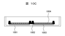
- FIG. 10C is a diagram showing the state of FIG. 10B as seen from the side.
- FIG. 13 is a diagram showing the state in which the frame, the base material, the cell sheet, and the support are packaged.
- FIG. 11 is a diagram showing a cell culture vessel according to a third embodiment of the present invention.
- FIG. 11B is an exploded view of the cell culture vessel of FIG.
- FIG. 11B is a diagram showing a modification of FIG. 11A.
- FIG. 11D is an exploded view of the cell culture vessel of FIG.
- Example 1 of the present invention With reference to Figures 1A to 8, a cell culture vessel according to Example 1 of the present invention and a cell culture device and a cell culture method using the same will be described.
- Fig. 1A is a plan view of the cell culture vessel seen from above.
- Fig. 1B is a cross-sectional view taken along the line A-A' in Fig. 1A.
- Fig. 1C is an exploded view of the cell culture vessel in Fig. 1B.
- Fig. 1D is a diagram showing a cell sheet being cultured using the cell culture vessel 101.
- FIGS. 1A to 1C show the structure of a cell culture vessel 101 and the removable culture member inside it.
- the removable culture member is made up of a frame 102 and a base material 103.
- the base material 103 allows cells to adhere and grow.
- the frame 102 is in contact with the periphery of the base material 103 in a perpendicular direction.
- the periphery of the substrate 103 is placed under the frame 102, so that although the medium is present in the substrate 103 during culture, it is possible to prevent the substrate 103 from changing position or floating. Also, since cells do not grow on the periphery of the substrate 103 located under the frame 102, after culturing cells and removing the frame 102, the substrate 103 can be taken out without damaging the cultured cells by grasping the periphery of the substrate 103 on which the cells are not growing.
- the substrate 103 is independently placed in each section surrounded by the frame 102, and is not placed across adjacent sections.
- the frame 102 includes a material to which cells are not adhesive.
- the frame 102 is made of a material such as silicone, and is manufactured, for example, by casting.
- the surface of the frame 102 is made non-adhesive to cells due to the inherent properties of the material such as silicone, or by performing surface treatment such as plasma treatment after manufacturing. This prevents cells from adhering to the frame 102 during culture. Furthermore, even if cells adhere to the outside 104 of the frame 102, the frame 102 is non-cell-adhesive, so the cells will not migrate to other compartments.
- the cross-sectional shape of the frame 102 is, for example, a trapezoid as shown in FIG. 1B. It may be another shape as described later in Example 2 (FIGS. 9A to 9E).
- the height of the frame 102 is, for example, about 1 mm, which is about 1000 times the cell diameter.
- the height of the frame 102 is set so as not to impede the movement of the culture medium during rocking during cell seeding and medium replacement, which will be described later. Specifically, the height of the frame 102 should be lower than the sidewall of the cell culture vessel 101, and the height of the frame 102 should be about half the height of the sidewall of the cell culture vessel 101.
- the amount of culture medium differs depending on the cell type, but specifically, the height of the culture medium should be several mm to several cm, and the amount of culture medium should be enough to cover the frame 102.
- the frame 102 forms one or more compartments within the cell culture vessel 101.
- the size of each compartment is the same as the size of the cell sheet to be used for transplantation.
- a substrate 103 is placed in each compartment inside the frame 102, and cells are cultured on the substrate 103.
- the cell culture vessel 101 may be made non-adhesive to cells by the method described above. This makes the bottom surface of the cell culture vessel 101 outside the frame 104 non-adhesive to cells, preventing cells from adhering to the outside of the frame 104.
- the substrate 103 should be larger than the area of each compartment inside the frame 102, and when the substrate 103 is pressed down by the frame 102, the area of the exposed substrate 103 should be the same as the size of the cell sheet to be used for transplantation.
- the substrate 103 is preferably a thin film having a porous structure.
- the material of the substrate 103 may be any plastic, and specific examples include urethane acrylate, polyester acrylate, epoxy acrylate, polymethyl (meth)acrylate, ethoxylated bisphenol A acrylate, aliphatic urethane acrylate, polyester acrylate, polyethylene terephthalate, polystyrene, polycarbonate, acrylic modified alicyclic epoxide, bifunctional alcohol ether type epoxide, acrylic silicone, acrylic dimethyl siloxane, etc.
- fibrin glue or beriplast which are tissue adhesives, may be used.
- the substrate 103 is placed on the cell culture vessel 101, and then the frame 102 is placed on top of it.
- the substrate 103 may be attached to the frame 102 in advance by a method such as heat welding. In this case, it is desirable to attach the substrate 103 with enough strength that it can be easily removed from the frame 102 after culture by holding it with tweezers or the like. It is also possible to attach it firmly and then cut it with a scalpel or the like.
- a lid 105 is placed above the cell culture vessel 101 to cover the entire opening of the cell culture vessel 101 in order to prevent bacteria and the like from entering the cell culture vessel 101 from the outside during culture, causing biological contamination.
- the lid 105 may be made of the same material as the cell culture vessel 101, for example, and may be placed by a method such as thermal welding. Alternatively, the lid 105 may be placed by screwing or the like.
- the cell culture vessel 101 may have a medium supply pipe, exhaust pipe, air supply pipe, etc., depending on the shape of the cell culture device, and each pipe may be installed according to the medium exchange method and gas exchange method. These pipes are installed by penetrating the lid 105. Since the cell culture vessel 101 makes it possible to produce multiple cell sheets from one cell culture vessel 101, it is not necessary to have multiple supply pipes, exhaust pipes, or air supply pipes within the cell culture device.
- FIGS. 2A and 2B show modified examples.
- FIG. 2A shows a modified example of FIG. 1D
- FIG. 2B is an exploded view of the cell culture vessel in FIG. 2A.
- a lid 201 that is easy to open and close may be provided.
- the lid 201 has a concave shape in cross section, and is formed so that the inner side of the lid 201 fits with the outer side of the cell culture vessel 101 when the lid 201 is placed on the cell culture vessel 101.
- the lid 201 can be easily opened and closed by gripping the outer side of the lid 201. With this shape, when performing operations such as cell seeding and medium replacement, the lid 201 can be opened and closed aseptically in a safety cabinet or the like to perform the necessary work.
- the outside 104 of the frame body is made non-cell-adhesive, the cells that reach it will be removed when the medium is replaced. If the outside 104 of the frame body is made cell-adhesive, the cells will adhere, spread, and grow, but because the frame body 102 is non-cell-adhesive, they will not migrate to the compartments inside the frame body 102.
- the lid 105 is aseptically removed, and the frame 102 is also aseptically removed. Then, the substrate 103 is removed. Since the substrate 103 is simply placed on the cell culture vessel 101, it can be easily removed from the cell culture vessel 101 by, for example, grasping it with tweezers. In other words, the cultured cell sheets 107 can be easily removed one by one from the cell culture vessel 101.
- the substrate 103 is divided by the frame 102 into sections the same size as the cell sheet to be used for transplantation, there is no need to cut the cell sheet after culturing.
- One substrate may be used for one patient, or multiple substrates may be used for one patient.
- FIGS. 3A to 3D are all modified versions of FIG. 1A, and show examples of the shapes of the compartments inside the frame 102 of the cell culture vessel 101 described in FIGS. 1A to 1D.
- FIG. 3A the area of each compartment in FIG. 1A is reduced by the frame 302.
- FIG. 3B a single cell culture vessel 301 has compartments of multiple sizes by using the frame 302.
- FIG. 3B three sizes of compartments are shown: large, medium, and small.
- the shape of the compartments defined by the frame 302 is a circle.
- FIG. 3C shows an example having an exterior 304 of the frame
- FIG. 3D shows an example in which the area of the frame 302 is set wide and there is no exterior 304 of the frame.
- the size and shape of the compartments may be selected in an appropriate combination according to the size and shape of the transplant site.
- the shape of the compartments may be a shape other than a circle. Cell sheets of the desired size and shape can be produced, and the process of cutting the cell sheets, which requires skilled labor, can be omitted.
- Figures 4A to 4H show the process from culturing cell sheets in cell culture vessels to harvesting and packaging.
- Figure 4A shows the state immediately after culture.
- a frame 402 and a substrate 403 are placed inside a cell culture vessel 401, and a cell sheet 404 is attached onto the substrate 403.
- a culture medium 405 is placed inside the cell culture vessel 401. After culture, the culture medium 405 is discharged and washed an appropriate number of times with physiological saline, phosphate buffered saline (PBS), or the like.
- the washing process may be performed automatically using a closed system cell culture device, or may be performed manually in a safety cabinet after removing the cell culture vessel 401 from the closed system cell culture device.
- the lid 406 is removed. If the above-described cleaning is performed manually in a safety cabinet, cleaning may be performed after removing the lid 406.
- the frame body 402 is grasped with tweezers or the like and removed aseptically. Because the frame body 402 is non-adhesive to cells, it is possible to remove only the frame body 402 without pulling up the cells on the substrate 403. If the frame body 402 were cell-adhesive, the cell sheet 404 on the substrate 403 and the frame body 402 would be connected via the cells, and the cell sheet 404 would move when the frame body 402 was lifted. To avoid this, the frame body 402 needs to be non-adhesive to cells.
- the substrate 403 to which the cell sheet 404 is adhered is grasped with tweezers or the like and aseptically removed from the cell culture vessel 401.
- the base material 403 and cell sheet 404 are placed on a support 407 that has been prepared in advance.
- the cell sheet 404 is placed so that it is in contact with the support 407.
- the support 407 may be a support made of fibrin glue or beriplast, which are tissue adhesives, or a hydrophilic PVDF membrane, nitrocellulose membrane, etc.
- packaging material 408 it is placed on top of packaging material 408, and another packaging material 408 is placed over the substrate 403, cell sheet 404, and support 407.
- the upper and lower packaging materials 408 are heat-sealed, and the substrate 403, cell sheet 404, and support 407 are sealed with the packaging material 408.
- the cells are transported to the operating room while maintaining appropriate temperature, pressure, and cleanliness.
- the packaging material 408 may be transported with the transport solution placed inside, using a transport solution inlet (not shown) and a transport solution outlet (not shown) attached to the packaging material 408.
- the time required for processing the cell sheet 404 can be reduced, and the impact of the atmosphere on the cell sheet 404 can be minimized.
- the cell sheet 404, substrate 403, and support 407 are aseptically removed from the packaging material 408, and as shown in FIG. 4H, the substrate 403 is peeled off from the cell sheet 404.
- the substrate 403 is grasped with tweezers or the like and peeled off from the cell sheet 404.
- the substrate 403 and cell sheet 404 may be treated with an enzyme such as dispase to decompose only the basal layer of the cell sheet 404, and then the substrate 403 may be grasped with tweezers or the like and removed as shown in FIG. 4H.
- the substrate 403 may be made a temperature-responsive culture surface, and may be made hydrophobic and cell-adhesive during culture, and after transportation, the temperature may be lowered to make it hydrophilic and cell-nonadhesive, and the substrate 403 may be grasped with tweezers or the like and removed as shown in FIG. 4H.
- the tissue adhesive before solidification may be placed on the cell sheet 404 as the support 407, and the tissue adhesive may be solidified to firmly integrate the cell sheet 404 and the tissue adhesive, and then the cell sheet 404 may be peeled off from the substrate 403 by lifting the support 407, which is the tissue adhesive, with tweezers. Since the cell sheet 404 and the tissue adhesive are firmly integrated, the cell sheet 404 can be easily peeled off from the substrate 403. When the support 407 is a tissue adhesive, the support 407 may also be transplanted.
- the support 407 is a hydrophilic PVDF membrane, nitrocellulose membrane, etc.
- the hydrophilic PVDF membrane, nitrocellulose membrane, etc. is removed after transplantation.
- the substrate 403 is not removed when packaged and then transported to the operating room, but the substrate 403 may be removed when packaged and then transported to the operating room. In that case, the substrate 403 is removed before packaging the cell sheet 404, and the substrate 403 is transported in a peeled state, which reduces the amount of work in the operating room.
- each component controlled by the control device 502 is connected to the cell culture vessel 501 arranged inside the incubator 503.
- the control device 502 is connected to a temperature adjustment unit 504 for controlling the temperature of the incubator 503, a gas concentration adjustment unit 506 for controlling the gas concentration in the incubator 503, a pump 507 installed in a closed system flow path circuit for automatically sending the culture medium in the cell culture vessel 501, a CO2/O2 sensor 508, a culture medium bag/culture supernatant bag 511, and a temperature sensor 550.
- a gas supply unit 505 is connected to the gas concentration adjustment unit 506, and gases such as CO2, O2, and N2 are supplied from the gas supply unit 505 to the gas concentration adjustment unit 506.
- the control device 502 corresponds to the processing unit and memory unit of a typical computer equipped with a processing unit consisting of a CPU (Central Processing Unit), a memory unit, an input/output unit consisting of a display device and a keyboard, and the display screen 509 corresponds to the display unit of the display device.
- a processing unit consisting of a CPU (Central Processing Unit)
- a memory unit storing data
- an input/output unit consisting of a display device and a keyboard
- the display screen 509 corresponds to the display unit of the display device.
- the control device 502 runs various programs stored in the memory unit on the CPU, which functions as a processing unit. This allows the temperature adjustment unit 504, gas supply unit 505, pump 507, CO2/O2 sensor 508, gas concentration adjustment unit 506, temperature sensor 550, and culture medium bag/culture supernatant bag 511 to control the culture environment in the incubator 503, enabling the implementation of a specified culture process in the cell culture vessel 501.
- Gas exchange within the cell culture vessel 501 is performed between the incubator 503 and the cell culture vessel 501 by a gas-permeable membrane installed in the cell culture vessel 501.
- the gas concentration adjustment unit 506 may be directly connected to the cell culture vessel 501.
- the temperature adjustment unit 504, the gas concentration adjustment unit 506, and the CO2/O2 sensor 508 may be configured to be directly connected to the cell culture vessel 501. In this configuration, gas is supplied directly into the cell culture vessel 501.
- FIG. 6 is a diagram showing the configuration of the flow path of the cell culture device of this embodiment.
- FIG. 6 shows an example of a closed system cell culture device having a closed system flow path including a removable culture member.
- the first container 602 and the second container 603 can be easily manufactured by those skilled in the art, taking into consideration their purpose and using the technical common sense of those skilled in the art.
- the first container 602 has an air pressure adjustment tube 605 that is open to the outside air via a filter 604, and has an end in the gas phase inside the container.
- the second container 603 has an air pressure adjustment tube 607 that is open to the outside air via a filter 606, and has an end in the gas phase inside the container.
- the closed cell culture device 601 has a first liquid delivery pipe 608 for delivering the first liquid in the first container 602, and a second liquid delivery pipe 609 for delivering the first liquid in the first liquid delivery pipe 608 to the second container 603.
- the second liquid delivery pipe 609 has a first liquid delivery pump 610, which adjusts the amount of liquid delivered in the second liquid delivery pipe 609.
- Each of the liquid delivery pipes 608, 609 can be easily manufactured using the technical common sense of a person skilled in the art.
- the first liquid delivery pipe 608 has a first valve 611, which can be alternately opened and closed with a second valve 613 that supplies air containing 5% concentration of CO2 through a filter 612, thereby switching between liquid delivery and air delivery.
- the closed system cell culture device 601 further includes a first discharge pipe 617 for discharging the first liquid in the second container (cell culture container) 603, and a second discharge pipe 618 connected to the first discharge pipe 617 and discharging the first liquid in the second container (cell culture container) 603 through the first discharge pipe 617 to the third container 614.
- a second liquid delivery pump 619 controls the amount of liquid delivered in the first discharge pipe 617.
- Each of the liquid delivery pipes 608, 609 and the discharge pipes 617, 618 can be easily manufactured using the technical common sense of a person skilled in the art.
- the second discharge pipe 618 has a third valve 620.
- the third valve 620 can be opened or closed to switch between delivering and not delivering liquid.
- FIGS. 7A to 7F show examples of screens of the system of the closed cell culture device of this embodiment. These are display examples of the display screen 509 in FIG. 5.
- FIGS. 7B and 7C show example screens displaying a list of patients to whom each cell sheet will be transplanted.
- FIG. 7B shows a list of patients scheduled for transplantation. Specifically, the patient number, patient ID, size of the cell sheet to be transplanted to each patient, the transplant medical institution to which the cell sheet will be transported, etc. are displayed.
- FIG. 7C shows the size of the cell sheet for each patient.
- Fig. 7D shows the selection screen (2) for the culture method.
- the closed cell culture device system presents the type of culture vessel to be used, as shown in Fig. 7D, based on the size of the cell sheet required for transplantation presented in Fig. 7C. It also presents the patient number associated with the cell sheet in each compartment.
- FIG. 7E shows the selection screen (3) for the culture method. After displaying FIG. 7D, the closed cell culture device system accepts the number of culture vessels to be used as an input, as shown in FIG. 7E.
- FIG. 7F shows the selection screen (4) for the culture method. Based on the input number of culture vessels, the closed cell culture device system outputs information on the closed flow path to be used for automatic culture, as shown in FIG. 7F.
- the medical institution to which the cells will be transported is decided according to the patient information shown in Figure 7, and an identification code is assigned to each cell culture vessel, frame, substrate within the frame's compartment, packaging, and transport container.
- the identification code may be character information, one-dimensional barcode, two-dimensional barcode, QR code, RFID tag, etc., and one or more may be selected and assigned. For example, if character information and an RFID tag are assigned, a human worker can recognize the content from the character information, and an electronic reader or the like can recognize the RFID tag, allowing the content to be confirmed in two ways.
- the information represented by the identification code is information on the patient to be transplanted, information on the cell sheet, information on the medical institution to which it is being transported, and an ID linked to this information.
- the identification code is used to manage the cell sheet after cultivation to prevent mix-ups during removal, packaging, packing into transport containers, and transportation. After cultivation, the cell sheet may be transported with the substrate 403 removed or without being removed, and the system of the closed cell culture device reflects this, as does the standard procedure manual that operators refer to when working.
- Types of support 407 include tissue adhesives, hydrophilic PVDF membranes, and nitrocellulose membranes, and these are also reflected in the system and standard procedure manual.
- a cell culture vessel is manufactured. Specifically, as shown in FIG. 1C, a cell culture vessel 101, a substrate 103, a frame 102, and a lid 105 are prepared. One or more substrates 103 are placed on the bottom of the cell culture vessel 101, and a frame 102 is placed on the periphery of the substrate 103. At this time, it is preferable to place the substrate 103 so that the frame 102 presses the periphery from above. As described above, this is to prevent the substrate 103 from changing position or floating. After that, a lid 105 that covers the entire opening of the cell culture vessel 101 is placed above the cell culture vessel 101.
- step S2 only the frame 102 may be placed on the bottom of the cell culture vessel 101, and the base material 103 may be placed in each compartment separated by the frame 102 after the flow path is installed in a subsequent step, for example, step S2.
- the lid 105 is placed after the base material 103 is placed in the cell culture vessel 101.
- the sterilization method is gamma ray sterilization, EOG sterilization, etc., and is selected appropriately based on the material and surface of the cell culture vessel being used. If a closed flow path is connected to the cell culture vessel, the closed flow path is also sterilized.
- Step S1 System Start> The system of the closed cell culture equipment is started.
- the equipment number and other information about the closed cell culture equipment to be used are written in the operation procedure manual.
- An electronic tag or two-dimensional barcode is pre-installed in the closed cell culture equipment, and by reading the electronic tag or two-dimensional barcode with a barcode reader or the like, it is confirmed in advance that it matches the equipment number and other information written in the operation procedure manual.
- the automatic culture schedule is determined in advance by the culture software, and this information is reflected in the closed system cell culture device.
- the automatic culture schedule also includes conditions such as the date and time, liquid volume, etc. for cell seeding, medium replacement, culture supernatant collection, tissue collection for testing, and tissue collection for transplantation.
- Step S2 Flow path installation> A closed flow path including a cell culture vessel is installed in a closed cell culture device.
- the cell type, the type of cell culture vessel including a frame having a predetermined number of compartments, the number of cell culture vessels, and the closed flow path to be used are determined according to the flow described in Figures 7A to 7F.
- step S0 if only the frame 102 is placed on the bottom of the cell culture vessel 101, the substrate 103 is placed in each compartment partitioned by the frame 102.
- the closed flow path consists of a cell culture vessel, a culture medium bag containing the culture medium, a culture supernatant bag for collecting the culture supernatant, etc., and the flow path tubes that connect them.
- the configuration depends on the type of closed flow path selected.
- the cell culture vessel, frame, and base material also have identification codes.
- Step S3 Cell seeding> A cell suspension that has been prepared to a specific concentration is placed in a cell bottle in advance in a safety cabinet, and then the bottle is placed in the closed cell culture device.
- the closed cell culture device delivers the cell suspension from the cell bottle to each cell culture vessel, and the cells are seeded.
- the cell suspension should be delivered in an amount sufficient to cover the frame.
- cell seeding may be performed manually in step S2.
- the cell suspension is manually placed in a cell culture vessel with a closed flow path in a safety cabinet.
- the height of the frame is sufficiently low that it does not affect the rocking motion during cell seeding. After the cells are uniformly dispersed in the medium in the cell culture vessel by rocking, the cells settle due to gravity and adhere to the culture surface formed by the substrate within the frame compartment.
- Step S4 Cultivation>
- the cells are cultured for a specified time on the substrate with the cells attached, with the cell culture vessel left stationary.
- the temperature is maintained at 37°C during the culture in an incubator.
- the air inside the closed cell culture device is constantly stirred by a fan to ensure that the temperature distribution is always uniform.
- a particle counter and a viable bacteria count measuring device can be attached to the closed cell culture device to monitor the cleanliness, improving the safety of production.
- gas exchange occurs between the gas phase inside the incubator and the gas phase inside the cell culture vessel via the gas-permeable membrane, filter, etc.
- gas exchange occurs by supplying a specific gas directly into the cell culture vessel. Gas exchange is performed several times a day during the culture period.
- the gas to be supplied is air containing a CO2 concentration of 5%.
- the gas is supplied to each cell culture vessel from a gas cylinder with the flow rate controlled by a gas flow meter and saturated with water molecules through a humidifier bottle. After supplying the gas to the cell culture vessel, unnecessary gas is discharged outside the flow path via a filter.
- the filter adjusts the pressure within the flow path as necessary.
- the filter used is of a quality that does not allow particles larger than 0.62 ⁇ m to pass through, for example.
- Step S5 Monitoring> An observation mechanism is used to obtain information about the cell state of the cell sheet during culture.
- the observation mechanism analyzes the cell proliferation rate, occupancy rate, cell state, etc. from the obtained cell images and culture supernatant.
- Information about the cell state can be obtained from a single culture vessel for multiple cell sheets, allowing efficient cell sheet culture.
- Steps S6 and S7 Culture medium replacement> If it is the day to change the medium, the medium change is performed. It is acceptable to simply add the medium.
- the medium stored in the refrigerator at 4°C is sent to the preheating bottle and preheated. The temperature may be raised while sending the medium at a low sending speed.
- the old medium is discharged from the cell culture vessel. The medium should be discharged to the height of the frame.
- the medium After the medium is discharged, new medium is promptly supplied into the cell culture vessel. The old medium is finally discharged into the culture supernatant bag. If necessary, the culture supernatant in the culture supernatant bag is collected and the cell growth state is evaluated by analyzing medium components such as glucose, lactic acid, and pH.
- Culture medium replacement may be performed by pushing out new medium while the old medium is still inside, or by simply adding new medium to the cell culture vessel.
- the closed system cell culture device may also determine whether or not to start medium replacement depending on the progress of the cell culture (step S6). If medium replacement is not required (NO in step S6), the closed system cell culture device returns to the processing of step S4. If medium replacement is required (YES in step S6), proceed to step S7 and perform medium replacement.
- Step S8 End of cell culture>
- the closed system cell culture device determines whether or not to terminate the cell culture depending on the progress of the cell culture. If the cell culture is to be terminated (YES in step S8), the process proceeds to step S9, where the cell culture vessel is collected from the closed system cell culture device and the cell sheet is collected. If the cell culture is not to be terminated (NO in step S8), the closed system cell culture device returns to the process of step S4.
- Step S9 Recovery of cell sheet>
- the cell sheet is collected according to the flow described in Figures 4A to 4D.
- the cell sheet is collected in a sterile environment.
- the sterile environment is, for example, in a safety cabinet, an isolator, or a clean bench.
- the lid is removed, and the frame is grasped with tweezers or the like and removed aseptically.
- the periphery of the substrate carrying the cell sheet is then grasped with tweezers or the like and removed aseptically.
- Step S10 Packaging of cell sheet> Following the flow described in Figures 4E to 4G, the removed substrate and cell sheet are placed on a support prepared in advance, the substrate, cell sheet, and support are placed on a packaging material, another packaging material is placed over the substrate, cell sheet, and support, and the upper and lower packaging materials are heat-sealed to package. Packaging may be performed with the substrate removed. If necessary, a transport solution is injected using a transport solution inlet and a transport solution outlet attached to the packaging material. The package has an identification code.
- Step S11 Transportation> After packaging, the product is transported to the medical institution where the transplant will be performed, according to the information on the identification code. In order to maintain quality during transport, the individual packaging is transported in an appropriate transport container that can maintain temperature, pressure, and cleanliness depending on the transportation method.
- Step S12 Transplantation>
- the cell sheet is removed from the transport container and aseptically removed from the packaging.
- organisms such as bacteria or particles may be attached to the outside of the individual packaging container, so it is opened aseptically to maintain cleanliness.
- the base material is removed from the cell sheet by the method described in FIG. 4H.
- the support is a tissue adhesive
- the cell sheet is transplanted including the support. If the support is a hydrophilic PVDF membrane, nitrocellulose membrane, etc., the hydrophilic PVDF membrane, nitrocellulose membrane, etc. are removed after transplantation.
- Step S13 End>
- the closed system flow path used for culture is removed, various software of the closed system cell culture apparatus is shut down, and the operation of the closed system cell culture apparatus is terminated.
- the closed system cell culture device and the cell culture vessel used therein configured as described above, by making the frame lower than the height of the sidewall of the cell culture vessel, multiple cell sheets can be automatically cultured simultaneously in the closed system cell culture device without being affected by the frame. In addition, after culture, the cell sheets can be removed without peeling them off from the cell culture vessel. Furthermore, according to this embodiment, the process of cutting the cell sheets to a size to be used for transplantation is not required, which results in improved manufacturing efficiency and reduced manufacturing costs.
- the frame and base material can be sterilized and reused.
- Example 2 A cell culture vessel and a cell culture method according to Example 2 of the present invention will be described with reference to Figures 9A to 10E.
- this Example an embodiment of a frame and a base material different from the cell culture vessel of Example 1 will be described. The following will focus on the differences from Example 1.
- the cross-sectional shape of frame body 901 may be a trapezoid, a triangle, a T-shape, a rectangle, an inverted trapezoid, or a shape that combines two or more of these shapes. Since the outer circumference of frame body 901 changes based on the cross-sectional shape of frame body 901, if a frame body with a long outer circumference is selected, cells adhered to the frame body can be prevented from migrating to other compartments. Furthermore, if the upper side of the cross-sectional shape of frame body 901 is longer than the lower side, such as the T-shape in Figure 9B or the inverted trapezoid in Figure 9C, cells can be prevented from climbing over the frame body.
- a recess may be provided in the center of the frame 901.
- cells adhered to the frame 901 are prevented from migrating to other compartments.
- the frame 1002 may be configured to be detachable into individual compartments, as shown in Figures 10A and 10B.
- One substrate 1003 is surrounded by one frame 1002, and cells are cultured within the compartments.
- Figure 10A shows the state during culture
- Figure 10B shows the state after one frame 1002 has been removed after culture.
- FIGS. 10C and 10D show the state of FIG. 10A and FIG. 10B as seen from the side, respectively.
- one frame body 1002 may be removed, and as shown in FIG. 10E, the frame body 1002, base material 1003, cell sheet 1004, and support 1005 may be packaged in packaging material 1006.
- the cultured cell sheet 1004 is surrounded by a frame 1002, so the cell sheet including the frame can be packaged and transported, and the frame 1002 can protect the cell sheet even if it is subjected to mechanical pressure or impact during transport.
- the material of the substrate 1003 may be plastic as in Example 1, and may be flat.
- the flat substrate 1003 is provided with cell adhesive properties by prior surface treatment or the like. In the case of a flat substrate 1003, it is possible to prevent the substrate from curling up or floating in the medium. When peeling off the cell sheet 1004, the flat substrate 1003 and cell sheet 1004 are removed by grasping them with tweezers or the like.
- the cell sheet 1004 may be cultured on a sheet-like substrate 1003 obtained by coating the inside of a compartment with tissue adhesive.
- the substrate 1003 is a tissue adhesive
- the cell sheet 1004 can be transplanted directly into a patient without peeling it off from the substrate 1003.
- Example 3 A cell culture vessel and a cell culture method according to Example 3 of the present invention will be described with reference to Figures 11A to 11D.
- this Example an embodiment of a frame and a base material different from those of the bottom surface of the cell culture vessel in Example 1 will be described. The following will focus on the differences from Example 1.
- the cell culture vessel of this embodiment differs from that of Example 1 in that a scaffold material 1104 is provided between the substrate 1103 and the cell culture vessel 1101.
- the scaffold material 1104 is, for example, alginic acid, collagen gel, laminin, tissue adhesive, etc.
- the base material 1103 may also be a membrane with many pore membranes, which are fine holes.
- FIG. 11C and 11D show a configuration having a frame 1108 serving as a foot between the bottom surface of the cell culture vessel 1101 and the substrate 1103.
- the substrate 1103 is sandwiched between the frame 1108 from above and below, and the upper and lower frame bodies 1108 are configured to be located vertically above the bottom surface of the cell culture vessel 1101, making it possible to have culture medium 1106 between the substrate 1103 and the cell culture vessel 1101.
- culture medium is supplied to the cells on the substrate 1103 from below as well, which has a positive effect on cell growth.
- the cell culture vessels according to Examples 1 to 3 described above allow the cultured cell sheet to be removed without peeling it off from the substrate. Furthermore, even in a closed cell culture device, it is possible to culture a cell sheet in a cell culture vessel having compartments, improving the efficiency of cell sheet production.
- the present invention is not limited to the above-described embodiments, but includes various modified examples and equivalent configurations within the spirit of the appended claims.
- the above-described embodiments have been described in detail to clearly explain the present invention, and the present invention is not necessarily limited to having all of the configurations described.
- part of the configuration of one embodiment may be replaced with the configuration of another embodiment.
- the configuration of another embodiment may be added to the configuration of one embodiment.
- part of the configuration of each embodiment may be added to, deleted from, or substituted for other configurations.
Landscapes
- Life Sciences & Earth Sciences (AREA)
- Engineering & Computer Science (AREA)
- Health & Medical Sciences (AREA)
- Bioinformatics & Cheminformatics (AREA)
- Chemical & Material Sciences (AREA)
- Wood Science & Technology (AREA)
- Organic Chemistry (AREA)
- Zoology (AREA)
- Biomedical Technology (AREA)
- Biotechnology (AREA)
- General Health & Medical Sciences (AREA)
- Sustainable Development (AREA)
- Microbiology (AREA)
- Biochemistry (AREA)
- General Engineering & Computer Science (AREA)
- Genetics & Genomics (AREA)
- Virology (AREA)
- Cell Biology (AREA)
- Medicinal Chemistry (AREA)
- Apparatus Associated With Microorganisms And Enzymes (AREA)
Abstract
1つの細胞培養容器で培養した複数枚の細胞シートを容易に取り外すことができる細胞培養容器を提供する。培養容器を仕切る枠体と、前記枠体によって仕切られた複数の区画において、前記培養容器の底面に前記区画毎に配置された基材と、を有し、前記基材は、前記区画毎に取り外し可能であることを特徴とする。
Description
本発明は、細胞培養容器の構造とそれを用いた細胞培養装置及び細胞培養方法に関する。
再生した組織、或いは細胞を用い、機能不全や損傷を起こした組織を回復させる再生医療は、従来治療法のなかった疾病に対する根治療法として期待される。再生医療の代表的な移植形態の一つに、細胞と細胞や、細胞と細胞外マトリックスが結合した細胞シートが挙げられる。今後見込まれる細胞シートの需要から、一定の品質を有する細胞シートを工業的に供給するために、複数の細胞シートを大量に培養、製造する技術の開発が求められている。
本技術分野の背景技術として、例えば、特許文献1のような技術がある。特許文献1では、温度応答性ポリマーを表面に被覆した培養皿に組み込んだ入れ子内で細胞を培養して細胞シートを得て、細胞付着部を具備した培養細胞移動治具により細胞シートを回収する工程を繰り返す方法が開示されている。
ところで、複数人分の細胞シートを培養装置で自動培養する場合、閉鎖系培養容器を用いて1患者分単位で培養すると培養装置の流路が複雑となる。よって、複数患者分を大面積の培養容器で製造する必要がある。
複数患者分の細胞シートを一度に製造する場合、大面積の細胞シートを培養容器の底面から剥離する必要がある。
また、その大面積の細胞シートを1患者分ずつ切断する必要がある。
しかしながら、特許文献1では、培養時は培養容器の底面に接着している細胞シートを、培養容器の底面から剥離せずに取り出すことは記載されていない。したがって、複数枚の細胞シートを培養容器から剥離するのに時間を要することが考えられる。
そこで、本発明の目的は、1つの細胞培養容器で培養した複数枚の細胞シートを容易に取り外すことができる細胞培養容器とそれを用いた細胞培養装置及び細胞培養方法を提供することにある。
上記課題を解決するために、本発明は、培養容器を仕切る枠体と、前記枠体によって仕切られた複数の区画において、前記培養容器の底面に前記区画毎に配置された基材と、を有し、前記基材は、前記区画毎に取り外し可能であることを特徴とする。
また、本発明は、培養容器を仕切る枠体と、前記枠体によって仕切られた複数の区画において、前記培養容器の底面に前記区画毎に配置された基材と、を有し、前記基材は前記区画毎に取り外し可能であり、前記枠体の高さは、前記培養容器の側壁の高さよりも低い細胞培養容器と、前記培養容器の開口部を覆う蓋と、培養液を収容する液体保持部と、前記蓋を貫通し、前記液体保持部から前記培養容器に前記培養液を供給する送液管と、前記蓋を貫通し、前記培養容器から前記培養液を排出する排出管と、を備えることを特徴とする。
また、本発明は、培養容器に細胞を含む培養液を供給し、枠体によって仕切られた複数の区画に配置され前記区画毎に取り外し可能な基材上で細胞シートを培養するステップと、前記枠体を取り外すステップと、培養した前記細胞シートが載った前記基材を取得するステップと、を有することを特徴とする。
本発明によれば、1つの細胞培養容器で培養した複数枚の細胞シートを容易に取り外すことができる細胞培養容器とそれを用いた細胞培養装置及び細胞培養方法を実現することができる。
これにより、細胞シートを培養容器から取り出す工程がより簡便となり、製造した細胞シートを効率的に移植現場へ運搬することができる。
上記した以外の課題、構成及び効果は、以下の実施形態の説明により明らかにされる。
以下、図面を用いて本発明の実施例を説明する。なお、各図面において同一の構成については同一の符号を付し、重複する部分についてはその詳細な説明は省略する。
図1Aから図8を参照して、本発明の実施例1に係る細胞培養容器とそれを用いた細胞培養装置及び細胞培養方法について説明する。
先ず、図1Aから図1Dに基づき、本実施例の細胞培養容器101の一構成を説明する。図1Aは、細胞培養容器を上から見た平面図である。図1Bは、図1AのA-A’断面図である。図1Cは、図1Bにおける細胞培養容器の分解図である。図1Dは、細胞培養容器101を用いて、細胞シートを培養している様子を示す図である。
図1Aから図1Cには、細胞培養容器101と、その内部にある取り外し培養部材の構成を示している。取り外し培養部材は、枠体102と基材103から成る。基材103は、細胞の接着や増殖を可能とする。枠体102は、基材103の周縁に対して、垂直方向に接する。
この構成により、基材103の周縁は、枠体102の下に置かれるため、培養中は基材103中に培地が存在するが、基材103の位置が変化したり浮かんだりすることを回避できる。また、枠体102の下部に位置する基材103の周縁では、細胞が生育しないため、細胞を培養し、枠体102を外した後、細胞が生育していない基材103の周縁を把持することにより、培養した細胞を傷つけずに基材103を取り出すことができる。基材103は、枠体102に囲まれる区画毎に独立して配置され、隣接する区画まで跨って配置されるものではない。 枠体102は、細胞が非接着な材質を含む。具体的には、枠体102は、シリコーン等の素材であり、例えば注型により製作する。枠体102は、シリコーン等の素材自身が有する性質により、または、製作後にプラズマ処理等の表面処理を行うことにより、枠体102の表面を細胞非接着性にする。これにより、培養中に枠体102上に細胞が接着することを回避する。また、枠体102の外部104に細胞が接着した場合であっても、枠体102が細胞非接着性であるため、他の区画まで、細胞が移動することはない。
枠体102の断面形状は、例えば図1Bに示す通り台形とする。実施例2(図9Aから図9E)で後述するように他の形状であっても良い。枠体102の高さは、例えば1mm程度とし、細胞径の約1000倍の高さとする。枠体102に高さを設けることにより、細胞が枠体102上に接着し、その上を移動したとしても、枠体102が形成する区画間の移動を妨げることを可能とする。
また、枠体102の高さは、後述する細胞播種時の揺動や培地交換において、培地の移動を妨げない程度の高さとする。具体的には、枠体102の高さは、細胞培養容器101の側壁よりも低ければ良く、枠体102の高さが細胞培養容器101の側壁の高さの二分の一程度の高さがあれば良い。また、培地量は細胞種により異なるが、具体的には、培地の高さは数mm~数cmとし、枠体102を覆う程度の培地量があると良い。
枠体102は、図1Aに示すように、細胞培養容器101内に1以上の区画を形成する。各区画の大きさは、移植に使用する細胞シートの大きさと同じである。枠体102の内側にある各区画の中に、基材103が設置され、基材103上で細胞を培養する。
細胞培養容器101は前述した方法により、細胞非接着性にしても良い。このことにより、枠体の外部104の細胞培養容器101の底面が細胞非接着性になり、枠体の外部104に細胞が接着するのを防ぐ。
基材103は、枠体102の内部にある各区画の面積より大きい基材を設置すれば良く、枠体102によって基材103を押さえた時に、露出した基材103の面積が移植に使用する細胞シートの大きさと同じであれば良い。
基材103は、多孔質を有する薄膜であることが望ましい。また、基材103の素材は、プラスチックであれば良く、具体的には、ウレタンアクリレート、ポリエステルアクリレート、エポキシアクリレート、ポリ(メタ)アクリル酸メチル、エトキシ化ビスフェノールAアクリレート、脂肪族ウレタンアクリレート、ポリエステルアクリレート、ポリエチレンテレフタレート、ポリスチレン、ポリカーボネート、アクリル変性脂環式エポキシド、2官能アルコールエーテル型エポキシド、アクリルシリコーン、アクリルジメチルシロキサン等が挙げられる。また、組織接着剤であるフィブリン糊やベリプラストであっても良い。
図1Cに示すように、細胞培養容器101の上に基材103を置き、枠体102を置く。枠体102へ基材103を熱溶着等の手段によりあらかじめ取り付けても良い。この場合、培養後、基材103を枠体102からピンセット等で把持する等の方法により簡単に取り外せる程度の強さで取り付けることが望ましい。強固に取り付け、メス等で切断しても良い。
細胞培養容器101の中に枠体102と基材103が設置された状態で、培養中に細胞培養容器101の外部から菌等が入り込み、生物学的汚染が生じることを回避するため、細胞培養容器101の上方に、細胞培養容器101の開口部全体を覆う蓋105を設置する。蓋105は、例えば細胞培養容器101と同じ素材とし、熱溶着等の方法により設置しても良い。または、ねじ止め等により蓋105を設置しても良い。
細胞培養容器101は、細胞培養装置の形態に合わせ、培地供給管、排出管、送気管等を有しても良く、培地交換方法、気体交換方法に応じて、各管を設置すれば良い。これらの管は蓋105を貫通して設置する。細胞培養容器101は、1つの細胞培養容器101に対して複数枚の細胞シートを製造することを可能にするため、細胞培養装置内で複数の供給管や排出管、送気管を備える必要はない。
図2A及び図2Bに、変形例を示す。図2Aは、図1Dの変形例を示す図であり、図2Bは、図2Aにおける細胞培養容器の分解図である。
図2A及び図2Bに示すように、蓋105に代えて、開閉が容易な蓋201を有しても良い。蓋201は、縦断面が凹形状を有しており、細胞培養容器101に蓋201を被せた際に、蓋201の内側の側面が細胞培養容器101の外側の側面と嵌合するように成形されている。蓋201の外側の側面を把持することで、容易に蓋201の開閉を行うことができる。このような形状とすることで、細胞播種、培地交換等の操作を実施する際、安全キャビネット等の中で無菌的に蓋201を開閉し、必要な作業を実施することができる。
図1Dに示すように、培養時、細胞を培地106と共に播種すると、枠体102の内側にある各区画内の基材103上に到達した細胞は、接着、伸展、増殖し、培養後にシート状になるまで増殖し、細胞シート107を形成する。枠体102は細胞非接着性であるため、この上に細胞は存在しない。
枠体の外部104に到達した細胞は、枠体の外部104を細胞非接着性とした場合、培地交換時に除去される。枠体の外部104を細胞接着性とした場合、細胞は、接着、伸展、増殖するが、枠体102が細胞非接着性であるため、枠体102の内側にある各区画まで移動することはない。
培養後、蓋105を無菌的に取り外し、枠体102を同じく無菌的に取り出す。そして基材103を取り出す。基材103は、細胞培養容器101の上に設置されているだけであるため、ピンセットで把持する等の方法により簡単に細胞培養容器101から取り出すことができる。つまり、培養した細胞シート107を細胞培養容器101から一枚ずつ、簡便に取り出すことができる。
また、基材103は、枠体102によって移植に使用する細胞シートの大きさと同じに仕切られているため、培養後に細胞シートを切断する必要はない。尚、1枚の基材を1患者分としても良いし、複数枚の基材を1患者分としても良い。
図3Aから図3Dは、いずれも図1Aの変形例であり、図1Aから図1Dで説明した細胞培養容器101の枠体102において、枠体102の内部にある各区画の形状の例を示した図である。図3Aは、枠体302によって、図1Aにおける各区画の面積を小さくしたものである。図3Bは、枠体302によって、1つの細胞培養容器301に複数種類の大きさの区画を有するものである。図3Bでは、大中小の3種類の大きさの区画を示している。図3C及び図3Dは、枠体302によって規定される区画の形状を円としたものである。図3Cは、枠体の外部304を有する例であり、図3Dは、枠体302の面積を広く設けて、枠体の外部304を設けない例である。
区画の大きさや形は、移植する移植部位の大きさや形状に合わせて、適宜組み合わせを選択しても良い。区画の形状は円以外の形状としても良い。所望の大きさ、形状の細胞シートを作製することができ、熟練の作業を必要とする細胞シートの切断工程を省くことができる。
図4Aから図4Hは、細胞培養容器での細胞シートの培養から回収、包装までの工程を示した図である。
図4Aは、培養直後の状態を示している。細胞培養容器401の内部に枠体402と基材403が設置され、基材403の上に細胞シート404が接着している。細胞培養容器401内には培地405が入れられている。培養後、培地405を排出し、生理食塩水、リン酸緩衝液(PBS:phosphate-buffered saline)等で適切な回数洗浄する。洗浄作業は、閉鎖系細胞培養装置を用いて自動で実施しても良いし、閉鎖系細胞培養装置から細胞培養容器401を取り外し、安全キャビネット内において手作業で実施しても良い。
続いて、図4Bに示すように、蓋406を取り外す。前述した洗浄を安全キャビネット内にて手作業で実施する場合は、蓋406を取り除いてから洗浄を行っても良い。
次に、図4Cに示すように、枠体402を、ピンセット等で把持し無菌的に取り外す。枠体402は細胞非接着性であるため、基材403上の細胞を引っ張り上げることなく、枠体402のみを取り外すことができる。枠体402が細胞接着性である場合、基材403上の細胞シート404と枠体402が、細胞を介して繋がってしまい、枠体402を持ち上げた時に細胞シート404も動いてしまう。これを回避するために、枠体402は細胞非接着性である必要がある。
次に、図4Dに示すように、細胞シート404が接着している基材403を、ピンセット等で把持し無菌的に細胞培養容器401から取り外す。
次に、図4Eに示すように、あらかじめ用意しておいた支持体407の上に、基材403と細胞シート404を乗せる。この時、細胞シート404が支持体407に接するように乗せる。支持体407は、組織接着剤であるフィブリン糊やベリプラストで作製した支持体の他に、親水性PVDF膜、ニトロセルロース膜等であっても良い。
そして、図4Fに示すように、包装材408の上に乗せ、さらに別の包装材408を基材403と細胞シート404と支持体407を覆うように被せる。
次に、図4Gに示すように、上下の包装材408を熱溶着し、基材403と細胞シート404と支持体407を包装材408で密封する。この状態で、適切に温度、圧力、清浄性を維持した状態で手術室まで輸送する。輸送時に、細胞の品質状態を保つため、包装材408に取り付けた輸送用溶液注入口(図示せず)と輸送用溶液排出口(図示せず)を用いて、包装材408内に輸送用溶液を入れた状態で輸送しても良い。
輸送する前に細胞シート404を基材403から剥離する工程を行わないため、細胞シート404の処理に係る時間を削減することができ、細胞シート404への大気の影響を最小限に抑えることができる。
輸送後、細胞シート404、基材403、及び支持体407を無菌的に包装材408から取り出し、図4Hに示すように、基材403を細胞シート404より剥離する。例えば、基材403をピンセット等で把持し、細胞シート404から剥離させる。
基材403及び細胞シート404に対し、例えばディスパーゼ等の酵素処理を行い、細胞シート404の基底層のみ分解を行ってから、図4Hのように、基材403をピンセット等で把持し、取り外しても良い。また、基材403を温度応答性培養表面とし、培養時は疎水性とし細胞接着性の状態で扱い、輸送後、温度を低下させて親水性とし、細胞非接着性の状態で扱い、図4Hのように、基材403をピンセット等で把持し、取り外しても良い。
また、固化する前の状態の組織接着剤を支持体407として細胞シート404に乗せ、組織接着剤を固化させることで細胞シート404と組織接着剤を強固に一体化させ、その後、組織接着材である支持体407をピンセットにより持ち上げることで、細胞シート404を基材403から剥離しても良い。細胞シート404と組織接着材を強固に一体化させている為、細胞シート404を基材403から剥離しやすくなる。支持体407が組織接着剤である場合、支持体407も含め移植することができる。
支持体407が親水性PVDF膜、ニトロセルロース膜等の場合、移植してから親水性PVDF膜、ニトロセルロース膜等は取り外す。
尚、図4F及び図4Gに示すように、基材403を取り外さない状態で包装してから手術室へ輸送しているが、基材403を取り外した状態で包装してから手術室へ輸送しても良い。その場合、細胞シート404を包装する前に、基材403を取り外し、基材403が剥離された状態で輸送することとなり、手術室での作業を減らすことができる。
以上のように構成された細胞培養容器によれば、培養した細胞シートを一枚ずつ、基材から剥離せずに細胞培養容器から取り出すことができ、細胞シートの取り出しを簡便化できる。また、細胞培養容器から細胞シートを取り出す際に、追加の装置等を準備することなく、細胞シートを取り出すことができる。 図5は、本実施例の細胞培養装置の概略構成を示す図である。本実施例の細胞培養容器は、閉鎖系細胞培養装置であっても、筐体型細胞培養装置であっても使用可能であるが、本実施例では閉鎖系細胞培養装置を用いた例を一例として示す。
図5に示すように、閉鎖系の細胞培養容器501を含む閉鎖系細胞培養装置は、制御装置502により制御される各構成要素が、インキュベータ503の内部に配置された細胞培養容器501に接続されている。制御装置502には、インキュベータ503の温度を制御するための温度調節部504と、インキュベータ503内の気体濃度を制御するための気体濃度調節部506と、細胞培養容器501内の培地を自動で送液するための閉鎖系流路回路に設置されたポンプ507と、CO2・O2センサ508と、培地バッグ・培養上清バッグ511と、温度センサ550が接続されている。気体濃度調節部506には気体供給部505が接続されており、気体供給部505から気体濃度調節部506に、CO2・O2・N2等の気体が供給される。
制御装置502は、CPU(Central Processing Unit:中央処理部)から成る処理部、記憶部、ディスプレイ装置及びキーボードから成る入出力部等を備えた通常のコンピュータにおける、処理部及び記憶部に対応し、表示画面509はディスプレイ装置の表示部に対応する。
制御装置502は、記憶部で記憶された各種プログラムを、処理部としてのCPU上で動作させる。これにより、温度調節部504、気体供給部505、ポンプ507、CO2・O2センサ508、気体濃度調節部506、温度センサ550、培地バッグ・培養上清バッグ511より、インキュベータ503中の培養環境を制御し、細胞培養容器501内での所定の培養工程の実施を可能とする。
細胞培養容器501内の気体交換は、細胞培養容器501に設置された気体透過膜により、インキュベータ503と細胞培養容器501との間でなされる。尚、気体濃度調節部506は、細胞培養容器501に直接接続しても良い。温度調節部504、気体濃度調節部506、CO2・O2センサ508は、細胞培養容器501に直接接続された構成でも構わない。この構成の場合、細胞培養容器501へは容器内へ直接気体を供給することとなる。
図6は、本実施例の細胞培養装置の流路の構成を示す図である。図6では、取り外し培養部材を含む閉鎖系流路を有する閉鎖系細胞培養装置の例を示している。
図6に示す閉鎖系細胞培養装置601は、第1の液体を保存するための第1の容器602と、第1の液体を入れるための第2の容器603を有する。第1の容器602は、第1の液体である細胞培養用の培地を保存しておく容器である。第2の容器603は細胞を培養する容器であり、細胞培養容器である。
第1の容器602、第2の容器603は、その目的を考慮し、当業者の技術常識により容易に作製可能である。第1の容器602は、フィルタ604を介して外気に開放している気圧調節管605を有し、容器内の気相に末端を有する。第2の容器603は、フィルタ606を介して外気に開放している気圧調節管607を有し、その末端を容器内の気相内に有する。
閉鎖系細胞培養装置601は、第1の容器602中の第1の液体を送液するための第1の送液管608と、第1の送液管608中の第1の液体を第2の容器603に送液するための第2の送液管609を有する。第2の送液管609は、第1の送液ポンプ610を有し、第2の送液管609内の送液量を調節する。それぞれの送液管608,609は、当業者の技術常識により容易に作製可能である。第1の送液管608は、第1の弁611を有し、フィルタ612を介して5%濃度のCO2を含む空気を供給する第2の弁613と交互に開閉することにより、送液と送気を切り替えることができる。
また、閉鎖系細胞培養装置601は、第2の容器(細胞培養容器)603中の第1の液体を排出するための第3の容器614を有する。第3の容器614は目的を考慮し、当業者の技術常識によって容易に作製可能である。第3の容器614は、フィルタ615を介して外気に開放している気圧調節管616を有し、容器内の気相部分に末端を有する。
閉鎖系細胞培養装置601はさらに、第2の容器(細胞培養容器)603内の第1の液体を排出するための第1の排出管617と、第1の排出管617に接続し、第2の容器(細胞培養容器)603中の第1の液体を、第1の排出管617を通じて第3の容器614に排出する第2の排出管618とを備える。第2の送液ポンプ619は、第1の排出管617内の送液量を制御する。それぞれの送液管608、609、排出管617、618は、当業者の技術常識により容易に作製可能である。第2の排出管618は、第3の弁620を有する。第3の弁620の開閉により送液の有無を切り替えることができる。
細胞培養容器である第2の容器603は、複数の容器を並列して接続することもできる。複数の細胞培養容器を接続する場合、第2の送液管609に分岐を設け、第5の弁621の設置と、所望の第4の容器622の数と同数の第6の弁623を設ければ良い。また、第1の液体の排出は、第1の排出管617に分岐を設け、第7の弁626の設置と、所望の第4の容器622の数と同数の第8の弁624を設ければ良い。第4の容器622の容器内圧調整のため、フィルタ606に接続するための分岐と、第4の容器622の数と同数の気圧調節管625を設置すれば良い。
図7Aから図7Fは、本実施例の閉鎖系細胞培養装置のシステムの画面例を示したものである。図5の表示画面509の表示例である。
図7Aは、培養方法に関する選択画面(1)を示している。閉鎖系細胞培養装置のシステムは、図7Aに示すように、細胞種、培養容器の種類、培養容器の個数、閉鎖系細胞培養装置の使用流路等の情報を入力として受け付ける。システムは、先に選択した項目の内容に応じて、その後に選択する項目では選択が可能なもののみを表示する。これにより、培養する細胞種や細胞種に対応する培養容器等における選択の間違いを回避することができる。尚、図7B以降の画面においてもこの機能は同様に有している。
図7B及び図7Cは、各細胞シートを移植する患者の一覧が表示される画面例を示している。図7Bには、移植予定の患者リストを示している。具体的には、患者No、患者ID、各患者に移植する細胞シートの大きさ、輸送先となる移植医療機関等を表示する。図7Cには、患者毎の細胞シートサイズを示している。
図7Dは、培養方法に関する選択画面(2)を示している。閉鎖系細胞培養装置のシステムは、図7Cで提示された移植に必要な細胞シートの大きさに基づき、図7Dに示すように、使用する培養容器の種類を提示する。また、各区画の細胞シートに紐づく患者のNO.を提示する。
図7Eは、培養方法に関する選択画面(3)を示している。閉鎖系細胞培養装置のシステムは、図7Dを表示後、図7Eに示すように、使用する培養容器の個数を入力として受け付ける。
図7Fは、培養方法に関する選択画面(4)を示している。閉鎖系細胞培養装置のシステムは、入力された培養容器の個数に基づき、図7Fに示すように、自動培養に使用する閉鎖系流路の情報を出力する。
前述の通り、培養後に図7に示した患者情報に従い、輸送する医療機関が決まるが、各細胞培養容器、枠体、枠体の区画内の基材、包装、輸送容器には識別符号が付与されている。識別符号は、文字情報、1次元バーコード、2次元バーコード、QRコード、RFIDタグ等であり、1つ、または複数を選択し付与する。例えば、文字情報とRFIDタグを付与した場合、作業者として人間が文字情報から内容を認識でき、電子読み取り機等がRFIDタグを認識でき、これにより二つの方法で内容を確認することができることとなる。
識別符号が表す情報は、移植する患者の情報、細胞シートの情報、輸送する医療機関等の情報、それらの情報と紐づけるID等である。培養後の細胞シートの剥離、包装、輸送容器への梱包、輸送等における取違防止のため、識別符号により管理を行う。また、培養後に基材403を外した状態で輸送する場合と、外さずに輸送する場合とがあるが、閉鎖系細胞培養装置のシステムはそれを反映したものとし、また作業者が作業時に参照する標準手順書においても反映されている。支持体407の種類は、組織接着剤、親水性PVDF膜、ニトロセルロース膜等があるが、それらもシステム、標準手順書へ反映されている。
以上の機能を有する閉鎖系細胞培養装置を用いて細胞シートを製造する一連の手順を図8に示す。
<ステップS0:細胞培養容器の事前準備>
先ず、事前準備として、細胞培養容器を製作する。具体的には、図1Cに示したように、細胞培養容器101、基材103、枠体102、蓋105を用意する。細胞培養容器101の底部に、1つまたは複数の基材103を配置し、さらに基材103の周縁に枠体102を配置する。この際、枠体102により基材103の周縁を上から押さえるように配置するのが好ましい。前述のように、基材103の位置が変化したり浮かんだりすることを回避するためである。この後、細胞培養容器101の上方に、細胞培養容器101の開口部全体を覆う蓋105を設置する。
先ず、事前準備として、細胞培養容器を製作する。具体的には、図1Cに示したように、細胞培養容器101、基材103、枠体102、蓋105を用意する。細胞培養容器101の底部に、1つまたは複数の基材103を配置し、さらに基材103の周縁に枠体102を配置する。この際、枠体102により基材103の周縁を上から押さえるように配置するのが好ましい。前述のように、基材103の位置が変化したり浮かんだりすることを回避するためである。この後、細胞培養容器101の上方に、細胞培養容器101の開口部全体を覆う蓋105を設置する。
なお、本ステップにおいて、細胞培養容器101の底部に枠体102のみを配置し、この後のステップ、例えばステップS2で流路を設置した後、枠体102によって仕切られた各区画に基材103を配置しても良い。この場合、蓋105は基材103を細胞培養容器101内に配置した後に設置する。
その後、製作された細胞培養容器は滅菌処理を行う。滅菌処理方法は、γ線滅菌、EOG滅菌等とし、使用している細胞培養容器の素材、表面から適切に選択する。細胞培養容器に閉鎖系流路が接続されている場合は、閉鎖系流路についても滅菌処理を行う。
<ステップS1:システムスタート>
閉鎖系細胞培養装置のシステムを起動させる。使用する閉鎖系細胞培養装置の情報として、装置番号等が作業手順書に記載されている。閉鎖系細胞培養装置には電子タグまたは2次元バーコードがあらかじめ設置されており、バーコードリーダ等により電子タグまたは2次元バーコードを読み取ることで、作業手順書に記載された装置番号等の情報と一致することを事前に確認する。
閉鎖系細胞培養装置のシステムを起動させる。使用する閉鎖系細胞培養装置の情報として、装置番号等が作業手順書に記載されている。閉鎖系細胞培養装置には電子タグまたは2次元バーコードがあらかじめ設置されており、バーコードリーダ等により電子タグまたは2次元バーコードを読み取ることで、作業手順書に記載された装置番号等の情報と一致することを事前に確認する。
作業者が制御装置にある操作部のスタートスイッチを押し起動する。続いて、制御部のディスプレイ(表示画面509)の操作画面にて閉鎖系細胞培養装置の内部環境が適切であることを確認する。例えばインキュベータの温度が37℃であることを確認する。これらの数値は限定的なものでなく、例えば温度は0℃から45℃の範囲より選択可能である。また自動培養スケジュールは事前に培養ソフトにて決定し、その情報は閉鎖系細胞培養装置へ反映されている。自動培養スケジュールには、細胞播種、培地交換、培養上清回収、検査用組織回収、移植用組織回収等がなされる日時、液量等の条件も含まれる。
<ステップS2:流路設置>
細胞培養容器を含む閉鎖系流路を閉鎖系細胞培養装置に設置する。事前に、図7Aから図7Fにて説明した流れに従い、細胞種、所定の区画数を有する枠体を含む細胞培養容器の種類、細胞培養容器の個数、使用する閉鎖系流路を決定する。尚、ステップS0において、細胞培養容器101の底部に枠体102のみを配置した場合は、枠体102によって仕切られた各区画に基材103を配置する。
細胞培養容器を含む閉鎖系流路を閉鎖系細胞培養装置に設置する。事前に、図7Aから図7Fにて説明した流れに従い、細胞種、所定の区画数を有する枠体を含む細胞培養容器の種類、細胞培養容器の個数、使用する閉鎖系流路を決定する。尚、ステップS0において、細胞培養容器101の底部に枠体102のみを配置した場合は、枠体102によって仕切られた各区画に基材103を配置する。
尚、閉鎖系流路は倉庫から搬出された段階で、閉鎖系流路にあらかじめ設置された電子タグまたは2次元バーコードを、バーコードリーダ等により読み取ることで、作業手順書に記載された装置番号等の情報と一致することを事前に確認している。閉鎖系流路は細胞培養容器、培地の入った培地バッグ、培養上清を回収する培養上清バッグ等と、それらを繋ぐ流路チューブから成る。構成は選択した閉鎖系流路の種類に応じたものとなる。識別符号は、細胞培養容器、枠体、基材も有している。
<ステップS3:細胞播種>
事前に安全キャビネット内で細胞ボトルへ、所定濃度に調製した細胞懸濁液を入れ、それを閉鎖系細胞培養装置に設置する。閉鎖系細胞培養装置が細胞ボトルから各細胞培養容器へ細胞懸濁液を送液し、細胞播種を行う。細胞懸濁液は枠体が覆われる程度の液量を送液すれば良い。
事前に安全キャビネット内で細胞ボトルへ、所定濃度に調製した細胞懸濁液を入れ、それを閉鎖系細胞培養装置に設置する。閉鎖系細胞培養装置が細胞ボトルから各細胞培養容器へ細胞懸濁液を送液し、細胞播種を行う。細胞懸濁液は枠体が覆われる程度の液量を送液すれば良い。
尚、細胞播種は、ステップS2において手作業で実施しても良い。その場合は安全キャビネット内で閉鎖系流路の細胞培養容器内に細胞懸濁液を手作業で入れる。
また、図1Bにて説明した通り、枠体の高さは十分に低いものであるため、枠体の高さが、細胞播種時の揺動に対し、影響を与えるものではない。揺動により細胞培養容器内の培地中に細胞が均一に分散した後、細胞は重力に従い沈降し、枠体の区画内の基材が形成する培養表面上に接着することとなる。
<ステップS4:培養>
細胞培養容器を静置した状態で、細胞が接着した基材において所定時間、培養する。培養中はインキュベータにより37℃に維持する。閉鎖系細胞培養装置内の空気はファンにより常に攪拌し、温度分布が常に一様となるようにする。尚、閉鎖系細胞培養装置にパーティクルカウンタや生菌数計測装置を取り付け、清浄度のモニタリングにより製造安全性の向上が可能である。
細胞培養容器を静置した状態で、細胞が接着した基材において所定時間、培養する。培養中はインキュベータにより37℃に維持する。閉鎖系細胞培養装置内の空気はファンにより常に攪拌し、温度分布が常に一様となるようにする。尚、閉鎖系細胞培養装置にパーティクルカウンタや生菌数計測装置を取り付け、清浄度のモニタリングにより製造安全性の向上が可能である。
気体交換は、気体透過膜、フィルタ等を有した細胞培養容器を使用する場合、インキュベータ内の気相と細胞培養容器内の気相は、気体透過膜、フィルタ等を介し気体交換される。送気用流路を有した細胞培養容器を使用する場合、細胞培養容器内へ直接所定の気体が送気されることにより気体交換がなされる。気体交換は培養期間中、1日に数回程度の頻度で実施する。
供給する気体は、例としてCO2濃度5%を含む空気を用いる。気体は、各細胞培養容器へガスボンベから気体フロメータにより流量を制御し、加湿ボトルを通して水分子を飽和させた状態で供給する。細胞培養容器へ送気後の不要な気体はフィルタを介して流路外へ排出する。フィルタは必要に応じて流路内の圧力を調整する。フィルタは、例えば0.62μm以上の粒子を通さない品質のものを使用する。
<ステップS5:モニタリング>
培養中の細胞シートに対し、観察機構を用いて細胞状態に関する情報を取得する。観察機構は、取得した細胞画像や、培養上清から、細胞の増殖率、占有率、細胞状態等を解析する。複数枚の細胞シートに対して、1つの培養容器から、細胞状態に関する情報を取得することができ、効率的に細胞シートを培養することができる。
培養中の細胞シートに対し、観察機構を用いて細胞状態に関する情報を取得する。観察機構は、取得した細胞画像や、培養上清から、細胞の増殖率、占有率、細胞状態等を解析する。複数枚の細胞シートに対して、1つの培養容器から、細胞状態に関する情報を取得することができ、効率的に細胞シートを培養することができる。
<ステップS6,S7:培地交換>
培地交換を行う日である場合、培地交換を実施する。培地を追加するだけの培地追加でも良い。冷蔵庫内で4℃にて保管されている培地を予熱ボトルまで送液し予熱する。低い送液速度で送液しながら昇温させても良い。培地交換では、最初に細胞培養容器から古い培地を排出する。培地は枠体の高さまで排出すれば良い。
培地交換を行う日である場合、培地交換を実施する。培地を追加するだけの培地追加でも良い。冷蔵庫内で4℃にて保管されている培地を予熱ボトルまで送液し予熱する。低い送液速度で送液しながら昇温させても良い。培地交換では、最初に細胞培養容器から古い培地を排出する。培地は枠体の高さまで排出すれば良い。
排出後、速やかに新しい培地を細胞培養容器内へ供給する。古い培地は最終的に培養上清バッグへ排出する。必要に応じて培養上清バッグ内の培養上清を回収し、グルコース、乳酸、pH等の培地成分分析により細胞の生育状態を評価する。
培地交換は、古い培地が入った状態で新しい培地を押し出す方式により実施しても良く、新しい培地を細胞培養容器内へ供給する培地追加のみでも良い。また、閉鎖系細胞培養装置は、細胞培養の進行状態によって、培地の交換を開始するか否かを判定しても良い(ステップS6)。培地の交換が必要ない場合(ステップS6においてNO)、閉鎖系細胞培養装置はステップS4の処理に戻る。培地の交換が必要な場合(ステップS6においてYES)、ステップS7に進み、培地交換を実施する。
<ステップS8:細胞培養終了>
閉鎖系細胞培養装置は、細胞培養の進行状態によって、細胞培養を終了するか否か判定を行う。細胞培養を終了する場合(ステップS8においてYES)、ステップS9に進み、細胞培養容器を閉鎖系細胞培養装置より回収し、細胞シートの回収を行う。細胞培養を終了しない場合(ステップS8においてNO)、閉鎖系細胞培養装置はステップS4の処理に戻る。
閉鎖系細胞培養装置は、細胞培養の進行状態によって、細胞培養を終了するか否か判定を行う。細胞培養を終了する場合(ステップS8においてYES)、ステップS9に進み、細胞培養容器を閉鎖系細胞培養装置より回収し、細胞シートの回収を行う。細胞培養を終了しない場合(ステップS8においてNO)、閉鎖系細胞培養装置はステップS4の処理に戻る。
<ステップS9:細胞シートの回収>
図4Aから図4Dにて説明した流れに従い、細胞シートを回収する。細胞シートの回収は、無菌環境で実施する。無菌環境とは、例えば安全キャビネット内、アイソレータ内、又はクリーンベンチ内である。蓋を取り外し、枠体をピンセット等で把持し無菌的に取り外す。そして細胞シートを有する基材の周縁を、ピンセット等で把持し無菌的に取り出す。
図4Aから図4Dにて説明した流れに従い、細胞シートを回収する。細胞シートの回収は、無菌環境で実施する。無菌環境とは、例えば安全キャビネット内、アイソレータ内、又はクリーンベンチ内である。蓋を取り外し、枠体をピンセット等で把持し無菌的に取り外す。そして細胞シートを有する基材の周縁を、ピンセット等で把持し無菌的に取り出す。
<ステップS10:細胞シートの包装>
図4Eから図4Gにて説明した流れに従い、取り出した基材と細胞シートを、あらかじめ用意しておいた支持体の上に乗せ、包装材の上に基材と細胞シートと支持体を乗せ、別の包装材を基材と細胞シートと支持体を覆うように被せて、上下の包装材を熱溶着することで包装する。基材を取り外した状態で包装しても良い。必要に応じて、包装材に取り付けた輸送用溶液注入口と輸送用溶液排出口を用い、輸送用溶液を注液する。尚、包装は識別符号を有している。
図4Eから図4Gにて説明した流れに従い、取り出した基材と細胞シートを、あらかじめ用意しておいた支持体の上に乗せ、包装材の上に基材と細胞シートと支持体を乗せ、別の包装材を基材と細胞シートと支持体を覆うように被せて、上下の包装材を熱溶着することで包装する。基材を取り外した状態で包装しても良い。必要に応じて、包装材に取り付けた輸送用溶液注入口と輸送用溶液排出口を用い、輸送用溶液を注液する。尚、包装は識別符号を有している。
<ステップS11:輸送>
包装後、識別符号の有する情報に従い、移植がなされる医療機関へ輸送する。個装容器は、輸送中において品質を維持できるよう、輸送手段に応じて、温度、圧力、清浄性を維持可能な適切な輸送容器を用いて輸送する。
包装後、識別符号の有する情報に従い、移植がなされる医療機関へ輸送する。個装容器は、輸送中において品質を維持できるよう、輸送手段に応じて、温度、圧力、清浄性を維持可能な適切な輸送容器を用いて輸送する。
<ステップS12:移植>
手術室へ到着後、細胞シートを輸送容器から取り出し、包装の中から無菌的に取り出す。開封時、個装容器の外側には菌等の生物や粒子が付着している可能性があるため、清浄性を維持するよう無菌的に開封する。開封後、図4Hにて説明した方法により、基材を細胞シートから取り外す。支持体が組織接着剤である場合、支持体も含め細胞シートを移植する。支持体が親水性PVDF膜、ニトロセルロース膜等の場合、移植してから親水性PVDF膜、ニトロセルロース膜等は取り外す。
手術室へ到着後、細胞シートを輸送容器から取り出し、包装の中から無菌的に取り出す。開封時、個装容器の外側には菌等の生物や粒子が付着している可能性があるため、清浄性を維持するよう無菌的に開封する。開封後、図4Hにて説明した方法により、基材を細胞シートから取り外す。支持体が組織接着剤である場合、支持体も含め細胞シートを移植する。支持体が親水性PVDF膜、ニトロセルロース膜等の場合、移植してから親水性PVDF膜、ニトロセルロース膜等は取り外す。
<ステップS13:終了>
閉鎖系細胞培養装置において、培養に用いた閉鎖系流路を取り外し、閉鎖系細胞培養装置の各種ソフトを終了させ、閉鎖系細胞培養装置の作動を終了させる。
閉鎖系細胞培養装置において、培養に用いた閉鎖系流路を取り外し、閉鎖系細胞培養装置の各種ソフトを終了させ、閉鎖系細胞培養装置の作動を終了させる。
以上のように構成された閉鎖系細胞培養装置、及びそれに使用する細胞培養容器によれば、枠体を細胞培養容器の側壁の高さよりも低くすることで、閉鎖系細胞培養装置で枠体に影響されることなく、複数枚の細胞シートを同時に自動培養できる。また、培養後、細胞シートを細胞培養容器から剥離することなく、取り出すことができる。また、本実施例によれば、移植に使用する大きさに細胞シートを切断する工程は不要となり、結果として製造効率が向上し、製造コストの低減が可能となる。
尚、枠体や基材は滅菌処理を行うことで、繰り返し使用しても良い。
図9Aから図10Eを参照して、本発明の実施例2に係る細胞培養容器及び細胞培養方法について説明する。本実施例では、実施例1の細胞培養容器とは異なる枠体及び基材の実施形態について説明する。以下、実施例1との差異を中心に説明する。
枠体901の断面形状は、図9Aから図9Eに示す通り、台形の他、三角形、T字型、四角形、逆台形でも良く、これらの図形を複数組み合わせた形状でも良い。枠体901の断面形状に基づき、枠体901の外周が変わる為、外周が長い枠体を選択した場合、枠体に接着した細胞が他の区画に移動することを防ぐことができる。更に、図9BのT字型や図9Cの逆台形のように、枠体901の断面形状の上辺が下辺よりも長い場合、細胞が枠体を乗り越えることを防ぐことができる。
尚、図9D及び図9Eのように、枠体901の中央に凹部を設けても良い。枠体901の中央に凹部を備えることにより、枠体901の上に接着した細胞が、他の区画に移動する際の妨げになる。
枠体1002は、図10A及び図10Bに示すように、区画毎に分離可能に構成しても良い。1枚の基材1003が1個の枠体1002で囲われており、区画内で細胞の培養を行う。図10Aは培養時の状態を示し、図10Bは培養後に1個の枠体1002を取り外した状態を示している。
図10C,図10Dは、それぞれ図10A,図10Bを横から見た状態を示している。図10Dのように1個の枠体1002を取り外し、図10Eに示すように、枠体1002と基材1003、細胞シート1004、支持体1005を含め、包装材1006内に包装しても良い。
図10Eでは、培養した細胞シート1004が枠体1002に囲われているため、枠体を含めて細胞シートを包装、輸送することができ、輸送中に細胞シートが機械的な圧力や衝撃等を受けても、枠体1002により保護することができる。
基材1003の素材は、実施例1と同様にプラスチックであれば良く、これらは平板状であっても良い。また、平板状の基材1003は事前に表面処理等により、細胞接着性を備えるものとする。平板状の基材1003の場合、基材の丸まりや、基材が培地中に浮遊することを防ぐことができる。細胞シート1004を剥離する時は、平板状の基材1003と細胞シート1004をピンセット等で把持して取り外す。
また、組織接着剤を区画内に被覆させることで得られたシート状の基材1003で細胞シート1004を培養しても良い。基材1003が組織接着剤である場合、細胞培養容器から組織接着剤と細胞シートを取り出した後、細胞シート1004を基材1003から剥離することなく、そのまま患者に移植することができる。
図11Aから図11Dを参照して、本発明の実施例3に係る細胞培養容器及び細胞培養方法について説明する。本実施例では、実施例1の細胞培養容器の底面と異なる枠体及び基材の実施形態について説明する。以下、実施例1との差異を中心に説明する。
図11A及び図11Bに示すように、本実施例の細胞培養容器は、実施例1に対し、基材1103と細胞培養容器1101の間に、足場材1104がある点において異なっている。足場材1104は、例えばアルギン酸、コラーゲンゲル、ラミニン、組織接着剤等である。
培養時、培地は足場材1104に浸潤する。よって、基材1103上の細胞は、下方からも培地が供給されることになる。この構成は、細胞の生育に良好な影響を与えることが可能となる。また、基材1103は、微細な孔であるポアメンブレンを多数有した膜であっても良い。
図11C及び図11Dは、細胞培養容器1101の底面と基材1103の間に足部となる枠体1108を有する構成である。図11Cに示すように、基材1103は、枠体1108に上下から挟まれ、上下の枠体1108は、細胞培養容器1101の底面から鉛直方向上方にある構成を有することで、基材1103と細胞培養容器1101の間に、培地1106を有することを可能とする。この構成により、基材1103上の細胞は、下方からも培地が供給され、細胞の育成に良好な影響を与える。
以上のように、上述した実施例1~実施例3に係る細胞培養容器によれば、培養した細胞シートを基材から剥離することなく、取り出すことができる。また、閉鎖系細胞培養装置であっても、区画を有する細胞培養容器における細胞シートの培養を可能にし、細胞シートの製造効率が向上する。
なお、本発明は前述した実施例に限定されるものではなく、添付した請求の範囲の趣旨内における様々な変形例及び同等の構成が含まれる。たとえば、前述した各実施例は本発明を分かりやすく説明するために詳細に説明したものであり、必ずしも説明した全ての構成を備えるものに本発明は限定されない。また、ある実施例の構成の一部を他の実施例の構成に置き換えても良い。また、ある実施例の構成に他の実施例の構成を加えても良い。また、各実施例の構成の一部について、他の構成の追加、削除、または置換をしても良い。
101…細胞培養容器、102…枠体、103…基材、104…枠体の外部、105…蓋、106…培地、107…細胞シート、201…蓋、301…細胞培養容器、302…枠体、303…基材、304…枠体の外部、401…細胞培養容器、402…枠体、403…基材、404…細胞シート、405…培地、406…蓋、407…支持体、408…包装材、501…細胞培養容器、502…制御装置、503…インキュベータ、504…温度調節部、505…気体供給部、506…気体濃度調節部、507…ポンプ、508…CO2・O2センサ、509…表示画面、511…培地バッグ・培養上清バッグ、550…温度センサ、601…閉鎖系細胞培養装置、602…第1の容器、603…第2の容器(細胞培養容器)、604…フィルタ、605…気圧調節管、606…フィルタ、607…気圧調節管、608…第1の送液管、609…第2の送液管、610…第1の送液ポンプ、611…第1の弁、612…フィルタ、613…第2の弁、614…第3の容器、615…フィルタ、616…気圧調節管、617…第1の排出管、618…第2の排出管、619…第2の送液ポンプ、620…第3の弁、621…第5の弁、622…第4の容器、623…第6の弁、624…第8の弁、625…気圧調節管、626…第7の弁、901…枠体、902…基材、1001…細胞培養容器、1002…枠体、1003…基材、1004…細胞シート、1005…支持体、1006…包装材、1101…細胞培養容器、1102…枠体、1103…基材、1104…足場材、1105…細胞シート、1106…培地、1107…蓋、1108…枠体。
Claims (16)
- 培養容器を仕切る枠体と、
前記枠体によって仕切られた複数の区画において、前記培養容器の底面に前記区画毎に配置された基材と、を有し、
前記基材は、前記区画毎に取り外し可能であることを特徴とする細胞培養容器。 - 前記枠体は、前記基材の周縁に対して、垂直方向に接することを特徴とする請求項1に記載の細胞培養容器。
- 前記枠体は、前記基材の周縁を上から押さえることを特徴とする請求項1に記載の細胞培養容器。
- 前記枠体は、細胞非接着性を有することを特徴とする請求項1に記載の細胞培養容器。
- 前記培養容器は、細胞非接着性を有することを特徴とする請求項1に記載の細胞培養容器。
- 前記基材は、多孔質を有する薄膜であることを特徴とする請求項1に記載の細胞培養容器。
- 前記枠体の高さは、前記培養容器の側壁の高さよりも低いことを特徴とする請求項1に記載の細胞培養容器。
- 前記培養容器の開口部を覆う蓋を有する請求項1に記載の細胞培養容器。
- 前記枠体は、複数の前記区画を有することを特徴とする請求項1に記載の細胞培養容器。
- 前記枠体の断面は、上辺が下辺よりも長い形状又は前記枠体の上部に凹部を有する形状であることを特徴とする請求項1に記載の細胞培養容器。
- 前記基材は、平板状のプラスチックであることを特徴とする請求項1に記載の細胞培養容器。
- 前記培養容器の底面と前記薄膜の間に、足場材を有することを特徴とする請求項6に記載の細胞培養容器。
- 前記培養容器の底面と前記基材の間に、足部を有することを特徴とする請求項11に記載の細胞培養容器。
- 前記基材は、シート状の組織接着剤であることを特徴とする請求項1に記載の細胞培養容器。
- 培養容器を仕切る枠体と、前記枠体によって仕切られた複数の区画において、前記培養容器の底面に前記区画毎に配置された基材と、を有し、前記基材は前記区画毎に取り外し可能であり、前記枠体の高さは、前記培養容器の側壁の高さよりも低い細胞培養容器と、
前記培養容器の開口部を覆う蓋と、
培養液を収容する液体保持部と、
前記蓋を貫通し、前記液体保持部から前記培養容器に前記培養液を供給する送液管と、
前記蓋を貫通し、前記培養容器から前記培養液を排出する排出管と、を備えることを特徴とする細胞培養装置。 - 培養容器に細胞を含む培養液を供給し、枠体によって仕切られた複数の区画に配置され前記区画毎に取り外し可能な基材上で細胞シートを培養するステップと、
前記枠体を取り外すステップと、
培養した前記細胞シートが載った前記基材を取得するステップと、
を有する細胞培養方法。
Priority Applications (3)
| Application Number | Priority Date | Filing Date | Title |
|---|---|---|---|
| JP2024562429A JPWO2024121923A1 (ja) | 2022-12-06 | 2022-12-06 | |
| PCT/JP2022/044858 WO2024121923A1 (ja) | 2022-12-06 | 2022-12-06 | 細胞培養容器、細胞培養装置及び細胞培養方法 |
| TW112146345A TWI885613B (zh) | 2022-12-06 | 2023-11-29 | 細胞培養容器、細胞培養裝置及細胞培養方法 |
Applications Claiming Priority (1)
| Application Number | Priority Date | Filing Date | Title |
|---|---|---|---|
| PCT/JP2022/044858 WO2024121923A1 (ja) | 2022-12-06 | 2022-12-06 | 細胞培養容器、細胞培養装置及び細胞培養方法 |
Publications (1)
| Publication Number | Publication Date |
|---|---|
| WO2024121923A1 true WO2024121923A1 (ja) | 2024-06-13 |
Family
ID=91378772
Family Applications (1)
| Application Number | Title | Priority Date | Filing Date |
|---|---|---|---|
| PCT/JP2022/044858 Ceased WO2024121923A1 (ja) | 2022-12-06 | 2022-12-06 | 細胞培養容器、細胞培養装置及び細胞培養方法 |
Country Status (3)
| Country | Link |
|---|---|
| JP (1) | JPWO2024121923A1 (ja) |
| TW (1) | TWI885613B (ja) |
| WO (1) | WO2024121923A1 (ja) |
Citations (4)
| Publication number | Priority date | Publication date | Assignee | Title |
|---|---|---|---|---|
| JP2006006281A (ja) * | 2004-06-29 | 2006-01-12 | Toyo Univ | 細胞固定化基板ならびに細胞固定化方法 |
| JP2010233456A (ja) * | 2009-03-30 | 2010-10-21 | Kitakyushu Foundation For The Advancement Of Industry Science & Technology | 細胞集合体形成器具、細胞集合体培養器具、細胞集合体転写キット及び細胞集合体の培養方法 |
| JP2011004612A (ja) * | 2009-06-23 | 2011-01-13 | Hitachi Ltd | 培養基材、培養シート、及び細胞培養方法 |
| JP2020500028A (ja) * | 2016-11-24 | 2020-01-09 | アルヴェオリクス アーゲー | 細胞培養システム及び方法 |
Family Cites Families (4)
| Publication number | Priority date | Publication date | Assignee | Title |
|---|---|---|---|---|
| JP6806055B2 (ja) * | 2015-06-22 | 2021-01-06 | 東洋製罐グループホールディングス株式会社 | 細胞培養方法、細胞培養用治具および細胞培養装置 |
| EP3395939B1 (en) * | 2015-12-26 | 2022-02-09 | Nepa Gene Co., Ltd. | Cell sorting, culture, and growth vessel; and cell sorting, culture, and growth method |
| WO2017170993A1 (ja) * | 2016-03-31 | 2017-10-05 | 古河電気工業株式会社 | 細胞収容チップ及び該細胞収容チップを用いたスクリーニング方法 |
| WO2021075502A1 (ja) * | 2019-10-16 | 2021-04-22 | 国立研究開発法人理化学研究所 | 細胞シート製造装置、および細胞シート |
-
2022
- 2022-12-06 WO PCT/JP2022/044858 patent/WO2024121923A1/ja not_active Ceased
- 2022-12-06 JP JP2024562429A patent/JPWO2024121923A1/ja active Pending
-
2023
- 2023-11-29 TW TW112146345A patent/TWI885613B/zh active
Patent Citations (4)
| Publication number | Priority date | Publication date | Assignee | Title |
|---|---|---|---|---|
| JP2006006281A (ja) * | 2004-06-29 | 2006-01-12 | Toyo Univ | 細胞固定化基板ならびに細胞固定化方法 |
| JP2010233456A (ja) * | 2009-03-30 | 2010-10-21 | Kitakyushu Foundation For The Advancement Of Industry Science & Technology | 細胞集合体形成器具、細胞集合体培養器具、細胞集合体転写キット及び細胞集合体の培養方法 |
| JP2011004612A (ja) * | 2009-06-23 | 2011-01-13 | Hitachi Ltd | 培養基材、培養シート、及び細胞培養方法 |
| JP2020500028A (ja) * | 2016-11-24 | 2020-01-09 | アルヴェオリクス アーゲー | 細胞培養システム及び方法 |
Also Published As
| Publication number | Publication date |
|---|---|
| TW202424178A (zh) | 2024-06-16 |
| JPWO2024121923A1 (ja) | 2024-06-13 |
| TWI885613B (zh) | 2025-06-01 |
Similar Documents
| Publication | Publication Date | Title |
|---|---|---|
| CA2223525C (en) | Apparatus and method for maintaining and treating biological cells | |
| JP5894260B2 (ja) | 培養容器及び自動培養装置 | |
| US6238908B1 (en) | Apparatus and method for maintaining and growth biological cells | |
| US6228635B1 (en) | Portable cell growth cassette for use in maintaining and growing biological cells | |
| US5985653A (en) | Incubator apparatus for use in a system for maintaining and growing biological cells | |
| US6096532A (en) | Processor apparatus for use in a system for maintaining and growing biological cells | |
| EP3194150B1 (en) | Container for accommodating at least of a least one biologically active fluid and at least one preparatory fluid, and a method therefor | |
| WO2016157322A1 (ja) | 閉鎖系培養容器、輸送方法、及び自動培養装置 | |
| JP5866006B2 (ja) | 培養容器及び自動培養装置 | |
| JP6664692B2 (ja) | 接着系細胞用の閉鎖系培養容器 | |
| JP5315640B2 (ja) | 接着性細胞培養用袋状容器 | |
| JPWO2012020458A1 (ja) | 自動培養装置 | |
| US12247188B2 (en) | Cell culture chamber with improved cell-contacting surfaces | |
| WO2016117281A1 (ja) | 細胞培養容器、細胞培養方法、及び細胞培養容器の使用方法 | |
| WO2024121923A1 (ja) | 細胞培養容器、細胞培養装置及び細胞培養方法 | |
| US12612582B2 (en) | Cell culture system | |
| JP4459579B2 (ja) | 培養装置 | |
| HK40067934A (en) | Cell culture chamber with improved cell-contacting surfaces |
Legal Events
| Date | Code | Title | Description |
|---|---|---|---|
| 121 | Ep: the epo has been informed by wipo that ep was designated in this application |
Ref document number: 22967776 Country of ref document: EP Kind code of ref document: A1 |
|
| WWE | Wipo information: entry into national phase |
Ref document number: 2024562429 Country of ref document: JP |
|
| NENP | Non-entry into the national phase |
Ref country code: DE |
|
| 122 | Ep: pct application non-entry in european phase |
Ref document number: 22967776 Country of ref document: EP Kind code of ref document: A1 |