WO2024004117A1 - 筒内直接噴射式火花点火内燃機関の噴射量制御方法および装置 - Google Patents
筒内直接噴射式火花点火内燃機関の噴射量制御方法および装置 Download PDFInfo
- Publication number
- WO2024004117A1 WO2024004117A1 PCT/JP2022/026144 JP2022026144W WO2024004117A1 WO 2024004117 A1 WO2024004117 A1 WO 2024004117A1 JP 2022026144 W JP2022026144 W JP 2022026144W WO 2024004117 A1 WO2024004117 A1 WO 2024004117A1
- Authority
- WO
- WIPO (PCT)
- Prior art keywords
- injection
- injection amount
- combustion
- equivalence ratio
- ratio
- Prior art date
- Legal status (The legal status is an assumption and is not a legal conclusion. Google has not performed a legal analysis and makes no representation as to the accuracy of the status listed.)
- Ceased
Links
Images



Classifications
-
- F—MECHANICAL ENGINEERING; LIGHTING; HEATING; WEAPONS; BLASTING
- F02—COMBUSTION ENGINES; HOT-GAS OR COMBUSTION-PRODUCT ENGINE PLANTS
- F02D—CONTROLLING COMBUSTION ENGINES
- F02D41/00—Electrical control of supply of combustible mixture or its constituents
- F02D41/30—Controlling fuel injection
- F02D41/32—Controlling fuel injection of the low pressure type
- F02D41/34—Controlling fuel injection of the low pressure type with means for controlling injection timing or duration
-
- F—MECHANICAL ENGINEERING; LIGHTING; HEATING; WEAPONS; BLASTING
- F02—COMBUSTION ENGINES; HOT-GAS OR COMBUSTION-PRODUCT ENGINE PLANTS
- F02D—CONTROLLING COMBUSTION ENGINES
- F02D43/00—Conjoint electrical control of two or more functions, e.g. ignition, fuel-air mixture, recirculation, supercharging or exhaust-gas treatment
Definitions
- the present invention relates to an in-cylinder direct injection spark ignition internal combustion engine that generates a stratified mixture through multistage injection of fuel injectors into a cylinder and ignites it with a spark plug.
- This invention relates to injection amount control during control that periodically repeats lean combustion smaller than 1.
- the internal combustion engine of Patent Document 1 performs stratified combustion by dividing injection into intake stroke injection (early injection) and compression stroke injection (late injection), and the air-fuel ratio in the combustion chamber is divided into rich side and lean side. When changing periodically, both the intake stroke injection and the compression stroke injection are increased or decreased.
- the air-fuel ratio distribution (gradation of air-fuel ratio density) near the ignition plug near the ignition timing is important.
- both the intake stroke injection and the compression stroke injection are increased or decreased when the air-fuel ratio of the combustion chamber is periodically changed between the rich side and the lean side as in Patent Document 1
- the air-fuel ratio distribution near the spark plug is This results in relatively large changes, resulting in variations in flame growth.
- the present invention provides an injection amount control method for an in-cylinder direct injection spark ignition internal combustion engine in which a stratified mixture is generated by multi-stage injection of a fuel injector into a cylinder and ignited by a spark plug.
- the multistage injection described above includes at least one early injection at a relatively early stage to generate a homogeneous mixture in the cylinder, and one injection near the ignition timing to generate a desired stratified mixture near the spark plug. and a late injection of During control that periodically repeats rich combustion where the target equivalence ratio is greater than 1 and lean combustion where the target equivalence ratio is less than 1, it responds to changes in the target equivalence ratio while making the late injection amount during rich combustion equal to the late injection amount during lean combustion. Early injection is now responsible for the increase/decrease in injection amount.
- FIG. 1 is an explanatory diagram of the configuration of an internal combustion engine according to an embodiment to which the present invention is applied.
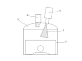
- FIG. 2 is an explanatory diagram schematically showing the configuration of one cylinder.
- FIG. 1 is an explanatory diagram showing a schematic configuration of an internal combustion engine 1 according to an embodiment to which the present invention is applied.
- An internal combustion engine 1 according to one embodiment is a 4-stroke cycle direct injection spark ignition internal combustion engine (so-called gasoline engine) with three cylinders in line, and a combustion chamber 5 of each cylinder has a pair of intake valves 2 and a pair of An exhaust valve 3 is provided, and a spark plug 4 is disposed in the center of the combustion chamber 5.
- a fuel injection valve 6 that injects high-pressure fuel into the cylinder is arranged at the top of the combustion chamber 5.
- the fuel injection valve 6 is configured to perform fuel injection by opening the valve body via a solenoid or piezoelectric element, etc., and the fuel injection amount basically depends on the fuel injection time (injection pulse width). It will be proportional.
- An electronically controlled throttle valve 10 whose opening degree is controlled by a control signal from an engine controller 9 is installed on the upstream side of the collector portion 8a of the intake passage 8 connected to the intake port 7 of each cylinder.
- the exhaust ports 12 of each cylinder are connected to branch portions of an exhaust manifold 13, and are gathered together as one exhaust passage by the exhaust manifold 13.
- a three-way catalyst 15 for purifying exhaust gas is provided at the outlet of the exhaust manifold 13.
- the three-way catalyst 15 is, for example, a so-called monolithic ceramic catalyst in which a catalyst layer containing a catalyst metal is coated on the surface of a monolithic ceramic body in which fine passages are formed.
- the three-way catalyst may include, in addition to the three-way catalyst 15 described above located at the outlet of the exhaust manifold 13, another three-way catalyst (for example, an underfloor catalyst) arranged in series on the downstream side. It's okay.
- An air-fuel ratio sensor 16 for detecting the exhaust air-fuel ratio is arranged on the inlet side of the three-way catalyst 15 in the exhaust passage 14, that is, at a position upstream of the three-way catalyst 15.
- This air-fuel ratio sensor 16 is a so-called wide-range air-fuel ratio sensor that can obtain an output according to the exhaust air-fuel ratio.
- a downstream air-fuel ratio sensor such as an O2 sensor may be additionally provided.
- the detection signal of the air-fuel ratio sensor 16 is input to the engine controller 9. Further, the engine controller 9 includes an air flow meter 20 on the upstream side of the throttle valve 10 to detect the amount of intake air, a crank angle sensor 21 to detect the engine rotation speed and crank angle position, and a water temperature sensor 22 to detect the cooling water temperature. , an accelerator opening sensor 23 that detects the amount of depression of the accelerator pedal operated by the driver, and other sensors. Based on these input signals, the engine controller 9 optimally controls the fuel injection amount and injection timing by the fuel injection valve 6, the ignition timing by the spark plug 4, the opening degree of the throttle valve 10, etc.
- the illustrated example internal combustion engine 1 is one to which a stratification technology called the so-called spray guide method is applied, and as schematically shown in FIG.
- a fuel injection valve 6 is arranged adjacent to the spark plug 4 at the center of the ceiling surface of the combustion chamber 5 .
- the fuel injection valve 6 injects fuel toward the crown surface of the piston 11 so that the spray F crosses the side of the electrode portion of the spark plug 4, as shown as a spray F in FIG.
- at least one early injection at a relatively early stage is performed to generate a homogeneous mixture in the cylinder, and a desired stratified mixture is generated near the spark plug. Therefore, multistage injection including one late injection performed near the ignition timing is performed.
- the early injections include two injections each occurring between the intake stroke and the beginning of the compression stroke, for a total of three injections.
- the early injection forms a generally uniform homogeneous mixture in the cylinder, and the spray of the late injection near the ignition timing passes through this homogeneous mixture.
- This late injection forms the air-fuel ratio distribution (gradation of air-fuel ratio density) in the vicinity of the spark plug 4 appropriately, and the initial flame generated by ignition propagates through the portion with a relatively high air-fuel ratio and grows. This achieves stable stratified combustion.
- the engine controller 9 performs air-fuel ratio control to optimize the exhaust purification performance of the three-way catalyst 15.
- the air-fuel ratio control estimates the oxygen storage amount of the three-way catalyst 15 based on the exhaust air-fuel ratio detected by the air-fuel ratio sensor 16, and sets this oxygen storage amount to a target oxygen storage amount (usually an intermediate value of the oxygen storage capacity (e.g.
- the fuel injection amount (injection pulse width) of the fuel injection valve 5 is feedback-controlled so that the fuel injection amount (injection pulse width) is set to 50%, etc.).
- the exhaust air-fuel ratio is maintained near the stoichiometric air-fuel ratio.
- the engine controller 9 performs rich combustion with a large equivalence ratio during warm-up of the three-way catalyst 15, specifically, at a stage where the three-way catalyst 15 has warmed up to some extent but has not yet reached a sufficient activation temperature. Control is performed in which lean combustion with a small equivalence ratio is periodically repeated (hereinafter, for convenience, this is referred to as perturbation control).
- the exhaust air-fuel ratio of the exhaust gas flowing into the three-way catalyst 15 changes relatively greatly between rich and lean, so that the reaction between HC, etc. during rich combustion and oxygen during lean combustion becomes active. occurs, and the temperature rise of the catalyst is accelerated. Furthermore, we compared the air-fuel ratio of the gas in contact with the catalyst as perturbation control to prevent temporary deterioration of the catalyst (a phenomenon in which oxygen, HC, etc. adhere to the catalyst metal surface, reducing the catalyst metal surface area and reducing catalyst performance). By significantly changing the period of time, the poisonous substances covering the surface of the catalyst metal are peeled off and the reaction area of the catalyst is expanded, which also speeds up the warm-up of the catalyst. .
- the latter injection amount during rich combustion and the lean Control is performed so that the early injection is responsible for the increase or decrease in the injection amount corresponding to the change in the target equivalence ratio while making the latter injection amount equal to the later injection amount during combustion.
- FIG. 3 is a time chart showing the operation of each part during perturbation control in one embodiment.
- Column (a) shows flags corresponding to the operation/stop of the internal combustion engine 1, and in this time chart, as shown in the figure, the internal combustion engine 1 is started from a stopped state and is, for example, idled.
- Column (b) shows the temperature of the three-way catalyst 15 (so-called bed temperature), and as shown in the figure, the temperature gradually increases after the internal combustion engine 1 is started.
- Column (c) is a perturbation flag that instructs execution of perturbation control, and is turned ON between time t1 and time t2.
- a predetermined perturbation start temperature a temperature lower than the activation temperature but at which a certain degree of reaction can be obtained
- the perturbation control is turned off and the perturbation control ends.
- Column (f) shows the early injection split ratio, which is the proportion of the early injection amount in the total injection amount, and it repeats increases and decreases in response to perturbation control of the target equivalence ratio as described above.
- Column (g) shows the latter injection split ratio, which is the ratio of the latter injection amount to the total injection amount, and it repeats increases and decreases in response to perturbation control of the target equivalence ratio.
- the early injection split ratio in column (f) is large during the rich combustion period when the target equivalence ratio is greater than 1, and becomes small during the lean combustion period when the target equivalence ratio is smaller than 1.
- the late injection split ratio in column (g) is, conversely, small during the rich combustion period when the target equivalence ratio is greater than 1, and becomes large during the lean combustion period when the target equivalence ratio is smaller than 1. .
- each division ratio is set so that only the early injection is responsible for the increase or decrease in the target equivalence ratio, and the late injection amount does not change even if the total injection amount increases or decreases.
- At least one of the standard early injection split ratio and standard late injection split ratio when the target equivalence ratio is 1, that is, stoichiometric combustion, is the "standard split ratio" and is based on the operating conditions (load and rotation speed) of the internal combustion engine 1. It is set by, for example, a map search, etc., depending on the location.
- Column (h) shows the early injection amount obtained by multiplying the total injection amount by the early injection split ratio, and during perturbation control, increases and decreases in a manner corresponding to increases and decreases in the target equivalence ratio. Note that when the early injection includes multiple injections (for example, two injections) as described above, the early injection amount shown in column (h) is further divided.
- Column (i) shows the late injection amount obtained by multiplying the total injection amount by the late injection split ratio, and as shown in the figure, the ON/OFF of perturbation control and the target equivalence ratio during perturbation control. It remains constant regardless of increases or decreases. That is, although the total injection amount increases or decreases in accordance with the increase or decrease in the target equivalence ratio, the latter injection split ratio is set in such a way as to offset this, so as a result, the latter injection amount remains constant.
- the injection amount is increased or decreased in response to increases or decreases in the target equivalence ratio at an early stage. Since the injection is borne by the injection and the late injection amount is not increased or decreased, changes in the air-fuel ratio distribution near the spark plug 4 near the ignition timing are small, and both rich combustion and lean combustion have the same stability as stoichiometric combustion. You can get flame growth.
- the total injection amount is determined from the target equivalence ratio, and then the reference division ratio is corrected according to the target equivalence ratio to determine the early injection amount and the late injection amount during perturbation control.
- the reference division ratio is corrected according to the target equivalence ratio to determine the early injection amount and the late injection amount during perturbation control.
- other calculation procedures may be used. For example, by determining the late injection amount when the target equivalence ratio is 1 from the operating conditions, and maintaining this late injection amount even during perturbation control, and subtracting the latter injection amount from the required total injection amount, the It is also possible to obtain the injection amount, etc.
- One rich combustion period and one lean combustion period during perturbation control shown as changes in the target equivalence ratio in column (e) of FIG. 3 actually include rich combustion and lean combustion multiple times, that is, in multiple cylinders.
- M times of rich combustion that are performed continuously in a plurality of cylinders and M times of lean combustion that are performed continuously in the same manner are alternately performed in accordance with the combustion order.
- the number of times M is greater than or equal to the number N of cylinders included in the internal combustion engine 1 (three in one embodiment). That is, after rich combustion is performed once in all the cylinders of the plurality of cylinders, lean combustion is similarly performed once in all the cylinders of the plurality of cylinders.
- stoichiometric combustion may be performed with an equivalence ratio of 1 between rich combustion and lean combustion.
- the time chart in FIG. 4 shows, as an example, six repetition patterns in a three-cylinder engine.
- the combustion order is #1 cylinder ⁇ #3 cylinder ⁇ #2 cylinder.
- “R” indicates rich combustion
- “L” indicates lean combustion
- “S” indicates stoichiometric combustion.
- Patterns 1 and 2 are examples in which rich combustion and lean combustion are performed continuously the same number of times (that is, for multiple cylinders) without intervening stoichiometric combustion.
- rich combustion and lean combustion are each performed 10 times in succession, and both are repeated alternately.
- the reversal cycle of rich combustion/lean combustion is relatively long.
- Patterns 3 to 6 in FIG. 4 are examples in which stoichiometric combustion is performed at least once each during the transition from the rich combustion period to the lean combustion period and between the transition from the lean combustion period to the rich combustion period. Due to the presence of stoichiometric combustion in this manner, variations in combustion pressure and rotational fluctuations based on the difference between the combustion pressure during rich combustion and the combustion pressure during lean combustion are reduced. In addition, the example of the time chart of FIG. 3 mentioned above does not include stoichiometric combustion at the time of such a transition.
- pattern 3 rich combustion and lean combustion are each performed seven times in succession, and stoichiometric combustion is performed once each during the transition from rich combustion to lean combustion and between the transition from lean combustion to rich combustion.
- pattern 4 rich combustion and lean combustion are each performed seven times in succession, and stoichiometric combustion is performed twice each during the transition from rich combustion to lean combustion and between the transition from lean combustion to rich combustion.
- pattern 5 rich combustion and lean combustion are performed three times each in succession, and stoichiometric combustion is performed three times in succession during the transition from rich combustion to lean combustion and between the transition from lean combustion to rich combustion. It will be done. In other words, rich/stoichiometric/lean is performed in order for all cylinders once.
- pattern 6 rich combustion and lean combustion are each performed three times in succession, and stoichiometric combustion is performed once each during transition from rich combustion to lean combustion and between transition from lean combustion to rich combustion.
- the number of rich combustions and the number of lean combustions are equal. Furthermore, the range of change in the equivalence ratio to the rich side and the range of change in the equivalence ratio to the lean side are set to be equal to each other based on the stoichiometry in rich combustion and lean combustion of each cylinder. Therefore, in all of Patterns 1 to 6, the average exhaust air-fuel ratio is basically close to the stoichiometric air-fuel ratio. Therefore, the emission of NOx as well as HC is suppressed.
- the fuel injection amount (strictly speaking, injection pulse width) is fed back by air-fuel ratio feedback control that maintains the air-fuel ratio near the target air-fuel ratio (for example, the stoichiometric air-fuel ratio). Corrected.
- the feedback correction in this case is provided to both the early injection amount and the late injection amount.
- a feedback correction coefficient ⁇ is calculated by the feedback control system, and the final early injection quantity and late injection quantity are determined by multiplying both the early injection quantity and the latter injection quantity by this feedback correction coefficient ⁇ .
- the repeating pattern of rich combustion and lean combustion is not limited to the example shown in FIG. 2.
- An appropriate number M of rich combustion and lean combustion can be combined, and an appropriate number M of stoichiometric combustion can be included.
- These repeating patterns may be determined in advance in consideration of various requirements or conditions and used fixedly, or may have multiple repeating patterns and be used as a catalyst.
- An optimal repetition pattern may be selectively executed depending on the operating conditions of the internal combustion engine 1 during warm-up. For example, by selecting a repetition pattern, the reversal period of rich combustion/lean combustion can be made appropriate.
- rich combustion and lean combustion may be periodically repeated by making a specific cylinder a rich combustion cylinder and making other cylinders lean combustion cylinders.
- the present invention is not limited to an in-line three-cylinder internal combustion engine, but can be similarly applied to other types of multi-cylinder internal combustion engines.
Landscapes
- Engineering & Computer Science (AREA)
- Chemical & Material Sciences (AREA)
- Combustion & Propulsion (AREA)
- Mechanical Engineering (AREA)
- General Engineering & Computer Science (AREA)
- Electrical Control Of Air Or Fuel Supplied To Internal-Combustion Engine (AREA)
Abstract
内燃機関の排気マニホルドの出口部に三元触媒(15)が設けられている。早期噴射と後期噴射を含む燃料噴射弁(6)の多段噴射により成層燃焼を行う。触媒暖機のために当量比を大としたリッチ燃焼期間と当量比を小としたリーン燃焼期間とを周期的に繰り返すパータベーション制御を行う際に、目標当量比の増減変化に対応した噴射量変化は、均質混合気を形成する早期噴射が負担する。後期噴射量は、目標当量比変化に拘わらずに一定に保持される。後期噴射による点火時期付近における点火プラグ(4)近傍の空燃比分布が変化しないので、安定した火炎成長が得られる。
Description
この発明は、筒内へ向かう燃料噴射弁の多段噴射によって成層混合気を生成し、点火プラグによる点火を行う筒内直接噴射式火花点火内燃機関に関し、特に、目標当量比が1より大きいリッチ燃焼と1より小さいリーン燃焼とを周期的に繰り返す制御時の噴射量制御に関する。
特許文献1は、排気通路にNOx吸収触媒を備えたリーン燃焼機関を前提とするものであるが、NOx吸収触媒のリフレッシュのために、基準空燃比をA/F=15~16の範囲として燃焼室の空燃比をリッチ側とリーン側とに周期的に変化させることが開示されている。特許文献1の内燃機関は、吸気行程噴射(早期噴射)と圧縮行程噴射(後期噴射)とに分割噴射することで成層燃焼を行うものであり、燃焼室の空燃比をリッチ側とリーン側とに周期的に変化させるに際しては、吸気行程噴射と圧縮行程噴射の双方を増減変化させる構成となっている。
多段噴射によって成層化した混合気に点火プラグによる点火を行う内燃機関にあっては、点火時期付近における点火プラグ近傍の空燃比分布(空燃比の濃淡のグラデーション)が重要である。特許文献1のように燃焼室の空燃比をリッチ側とリーン側とに周期的に変化させるに際して、吸気行程噴射と圧縮行程噴射の双方を増減変化させる構成では、点火プラグ近傍の空燃比分布が比較的大きく変化してしまい、火炎成長にばらつきが生じる。
この発明は、筒内へ向かう燃料噴射弁の多段噴射によって成層混合気を生成し、点火プラグによる点火を行う筒内直接噴射式火花点火内燃機関の噴射量制御方法において、
上記多段噴射は、筒内に均質混合気を生成するための相対的に早い時期における少なくとも1回の早期噴射と、点火プラグ近傍に所望の成層混合気を生成するために点火時期近傍に行う1回の後期噴射と、を含み、
目標当量比が1より大きいリッチ燃焼と1より小さいリーン燃焼とを周期的に繰り返す制御時に、リッチ燃焼時の後期噴射量とリーン燃焼時の後期噴射量とを等しくしつつ目標当量比変化に対応した噴射量の増減を早期噴射が負担するようにした。
上記多段噴射は、筒内に均質混合気を生成するための相対的に早い時期における少なくとも1回の早期噴射と、点火プラグ近傍に所望の成層混合気を生成するために点火時期近傍に行う1回の後期噴射と、を含み、
目標当量比が1より大きいリッチ燃焼と1より小さいリーン燃焼とを周期的に繰り返す制御時に、リッチ燃焼時の後期噴射量とリーン燃焼時の後期噴射量とを等しくしつつ目標当量比変化に対応した噴射量の増減を早期噴射が負担するようにした。
このようにリッチ燃焼とリーン燃焼とを周期的に繰り返す制御時に後期噴射は噴射量の増減がないので、点火時期付近における点火プラグ近傍の空燃比分布の変化が小さくなり、安定した火炎成長を維持することができる。
以下、この発明の一実施例を図面に基づいて詳細に説明する。図1は、この発明が適用される一実施例の内燃機関1の概略的な構成を示した説明図である。一実施例の内燃機関1は、直列3気筒の4ストロークサイクルの筒内直接噴射式火花点火内燃機関(いわゆるガソリン機関)であって、各気筒の燃焼室5に、一対の吸気弁2と一対の排気弁3とが設けられているとともに、燃焼室5の中心部に点火プラグ4が配置されている。また、筒内に向けて高圧の燃料を噴射する燃料噴射弁6が、燃焼室5頂部に配置されている。燃料噴射弁6は、ソレノイドもしくは圧電素子等を介して弁体が開作動することで燃料噴射を行う構成のものであり、燃料噴射量は、基本的に、燃料噴射時間(噴射パルス幅)に比例したものとなる。
各気筒の吸気ポート7に接続された吸気通路8のコレクタ部8a上流側には、エンジンコントローラ9からの制御信号によって開度が制御される電子制御型スロットルバルブ10が介装されている。
各気筒の排気ポート12は、排気マニホルド13のブランチ部にそれぞれ接続されており、この排気マニホルド13によって1つの排気通路として集合している。そして、排気マニホルド13の出口部には、排気浄化のための三元触媒15が設けられている。三元触媒15は、例えば、微細な通路が形成されたモノリスセラミックス体の表面に触媒金属を含む触媒層をコーティングした、いわゆるモノリスセラミックス触媒である。なお、三元触媒として、排気マニホルド13の出口部に位置する上記の三元触媒15に加えて、下流側に直列に配置された他の三元触媒(例えば、床下触媒)を含む構成であってもよい。
排気通路14の三元触媒15の入口側つまり三元触媒15よりも上流側の位置には、排気空燃比を検出するための空燃比センサ16が配置されている。この空燃比センサ16は、排気空燃比に応じた出力が得られるいわゆる広域空燃比センサである。なお、三元触媒15の下流側に、空燃比センサ16を含む空燃比フィードバック制御系の較正や三元触媒15の劣化診断等のために、三元触媒15を通過した排気の組成に応答するO2センサ等からなる下流側の空燃比センサを付加的に備えていてもよい。
空燃比センサ16の検出信号は、エンジンコントローラ9に入力される。さらに、エンジンコントローラ9には、スロットルバルブ10の上流側において吸入空気量を検出するエアフロメータ20、機関回転速度ならびにクランク角位置を検出するためのクランク角センサ21、冷却水温を検出する水温センサ22、運転者に操作されるアクセルペダルの踏込量を検出するアクセル開度センサ23、等の多数のセンサ類の検出信号が入力されている。エンジンコントローラ9は、これらの入力信号に基づき、燃料噴射弁6による燃料噴射量および噴射時期、点火プラグ4による点火時期、スロットルバルブ10の開度、等を最適に制御している。
図示例の内燃機関1は、いわゆるスプレーガイド方式と呼ばれる成層化技術を適用したものであり、図2に概略を示すように、燃焼室5の天井面中央部分に点火プラグ4が配置されているとともに、この点火プラグ4に隣接して燃焼室5の天井面中央部分に燃料噴射弁6が配置されている。燃料噴射弁6は、図2に噴霧Fとして示すように、点火プラグ4の電極部側方を噴霧Fが横切るようにピストン11冠面へ向かって燃料を噴射する。運転条件に応じて成層燃焼を行う際には、筒内に均質混合気を生成するための相対的に早い時期における少なくとも1回の早期噴射と、点火プラグ近傍に所望の成層混合気を生成するために点火時期近傍に行う1回の後期噴射と、を含む多段噴射が行われる。一実施例では、早期噴射はそれぞれ吸気行程から圧縮行程初期の間に行われる2回の噴射を含み、計3回の噴射となる。早期噴射によって筒内に概ね一様の均質混合気が形成され、この均質混合気を点火時期近傍における後期噴射の噴霧が通過する。この後期噴射によって点火プラグ4近傍の空燃比分布(空燃比の濃淡のグラデーション)が適切に形成され、点火によって生じた初期火炎が比較的濃い空燃比の部分を伝わって成長していく。これにより、安定した成層燃焼が実現される。
エンジンコントローラ9は、内燃機関1の種々の制御の中の1つとして、三元触媒15による排気浄化性能を最適化するための空燃比制御を行う。空燃比制御は、空燃比センサ16が検出した排気空燃比に基づいて三元触媒15の酸素ストレージ量を推定し、この酸素ストレージ量が目標酸素ストレージ量(通常、酸素ストレージ容量の中間値(例えば50%等)に設定される)となるように燃料噴射弁5の燃料噴射量(噴射パルス幅)をフィードバック制御するものである。これにより、排気空燃比は理論空燃比近傍に保たれる。
このような空燃比フィードバック制御のためには、三元触媒15が活性温度に達していることが必要であり、例えば内燃機関1の始動後に三元触媒15が早期に活性温度に暖機されることが望ましい。そのため、エンジンコントローラ9は、三元触媒15の暖機中、詳しくは、三元触媒15がある程度は暖まっているものの十分な活性温度に達していない段階において、当量比を大としたリッチ燃焼と当量比を小としたリーン燃焼とを周期的に繰り返す制御(以下では、これを便宜上、パータベーション制御と呼ぶ)を行う。パータベーション制御では、三元触媒15に流入する排気の排気空燃比がリッチ/リーンに比較的大きく変動することで、リッチ燃焼の際のHC等とリーン燃焼の際の酸素との反応が積極的に生じ、触媒の温度上昇が促進される。さらに、触媒の一時劣化(触媒金属表面に酸素やHC等が付着して触媒金属表面積が減少し、触媒性能が低下する現象)に対して、パータベーション制御として触媒に接するガスの空燃比を比較的大幅に周期変動させることで、触媒金属表面を覆っていた被毒物質が剥がれ落ち、触媒の反応面積が拡大するので、これによっても触媒暖機が速やかなものとなる。。
ここで、本発明においては、パータベーション制御が成層燃焼の下でつまり燃料噴射を早期噴射と後期噴射とを含む多段噴射とした条件下で行われる場合に、リッチ燃焼時の後期噴射量とリーン燃焼時の後期噴射量とを等しくしつつ目標当量比変化に対応した噴射量の増減を早期噴射が負担するように制御する。
図3は、一実施例のパータベーション制御時の各部の動作を示すタイムチャートである。(a)欄は内燃機関1の運転・停止に対応したフラグを示しており、このタイムチャートでは、図示するように、内燃機関1の停止状態から始動して例えばアイドル運転がなされる。(b)欄は、三元触媒15の温度(いわゆるベッド温度)を示しており、図示するように、内燃機関1の始動後、徐々に温度上昇する。
(c)欄は、パータベーション制御の実行を指示するパータベーションフラグであり、時間t1~時間t2の間でONとなる。つまり、内燃機関1の始動後、三元触媒15の温度が所定のパータベーション開始温度(活性温度よりは低いがある程度の反応が得られる温度)に達したときにONとなってパータベーション制御が開始し、所定の活性温度に達したときにOFFとなってパータベーション制御が終了する。
(d)欄は、空燃比センサ16の検出空燃比を示しており、時間t1~時間t2の間、パータベーション制御に伴って空燃比が周期的に変動する様子が示されている。
(e)欄は、目標当量比を示しており、パータベーション制御の期間(t1~t2)中は、目標当量比が1より大きいリッチ燃焼期間と1より小さいリーン燃焼期間とが周期的に繰り返される。なお、目標当量比の増減変化の傾向が総噴射量の増減変化の傾向に基本的に対応する。一実施例においては、ストイキ(当量比=1)を基準としたリッチ側への当量比変化幅とリーン側への当量比変化幅とが等しく設定されている。
(f)欄は総噴射量の中で早期噴射量が占める割合である早期噴射分割比を示しており、上記のような目標当量比のパータベーション制御に対応して増減変化を繰り返す形となる。(g)欄は総噴射量の中で後期噴射量が占める割合である後期噴射分割比を示しており、やはり目標当量比のパータベーション制御に対応して増減変化を繰り返す形となる。ここで、(f)欄の早期噴射分割比は、目標当量比が1よりも大となるリッチ燃焼期間では大となり、目標当量比が1よりも小となるリーン燃焼期間では小となる。他方、(g)欄の後期噴射分割比は、逆に、目標当量比が1よりも大となるリッチ燃焼期間では小となり、目標当量比が1よりも小となるリーン燃焼期間では大となる。つまり、目標当量比の増減は早期噴射のみが負担し、総噴射量が増減しても後期噴射量が変化しないように、各々の分割比が設定される。
より具体的には、(f)欄の早期噴射分割比は、目標当量比が増減変化するパータベーション制御中は、目標当量比が1であるときの基準早期噴射分割比と目標当量比とを用いて、「早期噴射分割比=(基準早期噴射分割比+目標当量比-1)/目標当量比」として算出される。例えば、基準早期噴射分割比を「0.8」、目標当量比を「1.1」とすると、早期噴射分割比は「(0.8+1.1-1)/1.1=0.8182」となる。
他方、(g)欄の後期噴射分割比は、目標当量比が増減変化するパータベーション制御中は、目標当量比が1であるときの基準後期噴射分割比と目標当量比とを用いて、「後期噴射分割比=基準後期噴射分割比/目標当量比」として算出される。例えば、基準後期噴射分割比を「1-0.8」つまり「0.2」、目標当量比を「1.1」とすると、後期噴射分割比は「0.2/1.1=0.1818」となる。
なお、目標当量比が1つまりストイキ燃焼であるときの基準早期噴射分割比および基準後期噴射分割比は、その少なくとも一方が「基準分割比」として、内燃機関1の運転条件(負荷および回転速度)に応じて、例えばマップ検索等により設定される。
(h)欄は、総噴射量に早期噴射分割比を乗じることで得られる早期噴射量を示しており、パータベーション制御中は、目標当量比の増減変化に対応した形で増減変化する。なお、上述したように早期噴射が複数回(例えば2回)の噴射を含む場合には、(h)欄に示す早期噴射量がさらに分割されることとなる。
(i)欄は、総噴射量に後期噴射分割比を乗じることで得られる後期噴射量を示しており、図示するように、パータベーション制御のON・OFFおよびパータベーション制御中の目標当量比の増減変化に拘わらずに、一定となる。つまり、目標当量比の増減変化に応じて総噴射量が増減変化するが、これを相殺するような形に後期噴射分割比が設定されるので、結果として、後期噴射量は一定となる。
このように、上記実施例では、目標当量比が1より大きいリッチ燃焼と1より小さいリーン燃焼とを周期的に繰り返すパータベーション制御に際して、目標当量比の増減変化に対応した噴射量の増減を早期噴射が負担し、後期噴射量は増減しないようにしたので、点火時期付近における点火プラグ4近傍の空燃比分布の変化が小さくなり、リッチ燃焼およびリーン燃焼のいずれでもストイキ燃焼時と同様の安定した火炎成長を得ることができる。
なお、上記実施例では目標当量比から総噴射量を求めた上で、目標当量比に応じて基準分割比を補正することで、パータベーション制御中の早期噴射量および後期噴射量を求めるようにしているが、本発明においては、他の演算手順であってもよい。例えば、目標当量比が1であるときの後期噴射量を運転条件から求め、パータベーション制御中もこの後期噴射量を維持するようにして、必要な総噴射量から後期噴射量を減じることで早期噴射量を求める、等も可能である。
図3の(e)欄に目標当量比の変化として示したパータベーション制御中の1つのリッチ燃焼期間およびリーン燃焼期間は、実際には複数回つまり複数気筒でのリッチ燃焼およびリーン燃焼を含んでいる。すなわち、一実施例のパータベーション制御では、燃焼順序に従って複数気筒で連続的になされるM回のリッチ燃焼と同じく連続的になされるM回のリーン燃焼とを交互に行う。そして、回数Mは、内燃機関1に含まれる気筒数N(一実施例では3)以上となっている。すなわち、複数気筒の全ての気筒において1回はリッチ燃焼を行った後に、同様に複数気筒の全ての気筒において1回はリーン燃焼が行われる。なお、後述の例で示すように、リッチ燃焼とリーン燃焼との間に当量比を1としたストイキ燃焼を行うようにしてもよい。
図4のタイムチャートは、一例として、3気筒機関における6通りの繰り返しパターンを示している。3気筒機関においては、図示するように、燃焼順序は、♯1気筒→♯3気筒→♯2気筒、の順となる。図中の「R」はリッチ燃焼を、「L」はリーン燃焼を、「S」はストイキ燃焼を、それぞれ示している。
パターン1およびパターン2は、ストイキ燃焼を介在させずにリッチ燃焼とリーン燃焼とをそれぞれ同じ複数回(つまり複数気筒)連続的に行う例である。パターン1では、リッチ燃焼およびリーン燃焼がそれぞれ10回ずつ連続して行われ、両者が交互に繰り返し行われる。このパターン1は、リッチ燃焼/リーン燃焼の反転周期が比較的長いものとなる。
パターン2では、リッチ燃焼およびリーン燃焼がそれぞれ気筒数と等しい3回ずつ連続して行われ、両者が交互に繰り返し行われる。すなわち、全ての気筒でリッチ燃焼がなされた後に全ての気筒でリーン燃焼がなされる。
一般に円形ないし楕円形をなす三元触媒15の断面において、1つの気筒の排気ガスは、断面の一部の領域を通って流れる。つまり、1つの気筒の排気ガスが三元触媒15の断面全体に行き渡ることはない。これに対し、例えばパターン2では、全ての気筒においてリッチ燃焼を行うことでリッチな排気ガスが三元触媒15の断面全体に行き渡る。そして全ての気筒においてリーン燃焼を行うことでリーンな排気ガスが同様に三元触媒15の断面全体に行き渡る。そのため、パータベーション制御による作用(HC等の酸化作用および一次劣化の回復作用)が三元触媒15の全域で確実に得られる。
図4のパターン3~6は、リッチ燃焼期間からリーン燃焼期間へ移行する間およびリーン燃焼期間からリッチ燃焼期間へ移行する間にそれぞれ少なくとも1回のストイキ燃焼を行うようにした例である。このようにストイキ燃焼が介在することで、リッチ燃焼の際の燃焼圧とリーン燃焼の際の燃焼圧との差に基づく燃焼圧ばらつきや回転変動が小さくなる。なお、前述した図3のタイムチャートの例では、このような移行時のストイキ燃焼は含まれていない。
パターン3では、リッチ燃焼およびリーン燃焼がそれぞれ7回ずつ連続して行われ、リッチ燃焼からリーン燃焼へ移行する間およびリーン燃焼からリッチ燃焼へ移行する間にそれぞれ1回のストイキ燃焼が行われる。パターン4では、リッチ燃焼およびリーン燃焼がそれぞれ7回ずつ連続して行われ、リッチ燃焼からリーン燃焼へ移行する間およびリーン燃焼からリッチ燃焼へ移行する間にそれぞれ2回のストイキ燃焼が行われる。
パターン5では、リッチ燃焼およびリーン燃焼がそれぞれ3回ずつ連続して行われ、リッチ燃焼からリーン燃焼へ移行する間およびリーン燃焼からリッチ燃焼へ移行する間に同じく3回ずつ連続してストイキ燃焼が行われる。つまり、全気筒で1回ずつ、リッチ/ストイキ/リーンを順に行う形となる。パターン6では、リッチ燃焼およびリーン燃焼がそれぞれ3回ずつ連続して行われ、リッチ燃焼からリーン燃焼へ移行する間およびリーン燃焼からリッチ燃焼へ移行する間にそれぞれ1回のストイキ燃焼が行われる。
図4のパターン1~6のいずれも、リッチ燃焼の回数とリーン燃焼の回数とが等しい。また、各気筒のリッチ燃焼およびリーン燃焼におけるストイキを基準としたリッチ側への当量比変化幅とリーン側への当量比変化幅とは互いに等しく設定されている。従って、パターン1~6のいずれも、基本的に平均的な排気空燃比は理論空燃比近傍にある。そのため、HCとともにNOxの排出が抑制される。
図3のタイムチャートでは詳細な図示を省略しているが、空燃比を目標空燃比(例えば理論空燃比)近傍に維持する空燃比フィードバック制御によって燃料噴射量(厳密には噴射パルス幅)がフィードバック補正される。好ましい一実施例では、この場合のフィードバック補正分は、早期噴射量および後期噴射量の双方に与えられる。例えば、フィードバック制御系によってフィードバック補正係数αが算出され、このフィードバック補正係数αを早期噴射量および後期噴射量の双方に乗じることで、最終的な早期噴射量および後期噴射量が決定される。これは、例えば燃料噴射弁6の製品ばらつき等によって噴射パルス幅に対し実燃料噴射量が過不足を生じているような場合に、その過不足がフィードバック補正によって補償されることを考慮したものである。つまり、噴射パルス幅に対し実燃料噴射量に過不足がある場合には、後期噴射による所期の空燃比分布が得られないので、後期噴射量についてもフィードバック補正を加えた方が望ましい。
リッチ燃焼およびリーン燃焼の繰り返しパターンは、図2の例に限られない。適当な数Mのリッチ燃焼とリーン燃焼とを組み合わせ、さらに適当な数のストイキ燃焼を含めることができる。これらの繰り返しパターンは、予め種々の要求ないし条件を考慮していずれかの繰り返しパターンに決定し、これを固定的に用いるようにしてもよく、あるいは、複数の繰り返しパターンを有していて、触媒暖機中の内燃機関1の運転条件に応じて最適な繰り返しパターンを選択的に実行するようにしてもよい。例えば、繰り返しパターンの選択により、リッチ燃焼/リーン燃焼の反転周期を適切なものとすることができる。また、特定気筒をリッチ燃焼気筒とし、その他の気筒をリーン燃焼気筒とすることで、リッチ燃焼とリーン燃焼とを周期的に繰り返すようにしてもよい。
以上、この発明を直列3気筒内燃機関に適用した一実施例を説明したが、この発明は直列3気筒内燃機関に限らず、他の形式の多気筒内燃機関に同様に適用することができる。
Claims (7)
- 筒内へ向かう燃料噴射弁の多段噴射によって成層混合気を生成し、点火プラグによる点火を行う筒内直接噴射式火花点火内燃機関の噴射量制御方法において、
上記多段噴射は、筒内に均質混合気を生成するための相対的に早い時期における少なくとも1回の早期噴射と、点火プラグ近傍に所望の成層混合気を生成するために点火時期近傍に行う1回の後期噴射と、を含み、
目標当量比が1より大きいリッチ燃焼と1より小さいリーン燃焼とを周期的に繰り返す制御時に、リッチ燃焼時の後期噴射量とリーン燃焼時の後期噴射量とを等しくしつつ目標当量比変化に対応した噴射量の増減を早期噴射が負担するようにした、
筒内直接噴射式火花点火内燃機関の噴射量制御方法。 - 目標当量比が1であるときの早期噴射と後期噴射の各噴射量を所定の基準分割比に従って設定するとともに、
目標当量比が1より大きいリッチ燃焼時および1より小さいリーン燃焼時の後期噴射量が目標当量比が1であるときの後期噴射量と等しくなるように分割比を変更する、
請求項1に記載の筒内直接噴射式火花点火内燃機関の噴射量制御方法。 - 上記早期噴射はそれぞれ吸気行程から圧縮行程初期の間に行われる2回の噴射を含む、
請求項1に記載の筒内直接噴射式火花点火内燃機関の噴射量制御方法。 - 排気通路に三元触媒を備え、この三元触媒の暖機中に、当量比を大としたリッチ燃焼と当量比を小としたリーン燃焼とを周期的に繰り返す上記の制御を行う、
請求項1に記載の筒内直接噴射式火花点火内燃機関の噴射量制御方法。 - 上記燃料噴射弁は、上記点火プラグに隣接して燃焼室天井面中央部分に配置され、均質混合気を通過する後期噴射の噴霧により生じた成層混合気に点火を行う、
請求項1に記載の筒内直接噴射式火花点火内燃機関の噴射量制御方法。 - 平均空燃比を理論空燃比近傍に保つように空燃比フィードバック制御を行い、
このフィードバック制御における補正を早期噴射および後期噴射双方に加える、
請求項1に記載の筒内直接噴射式火花点火内燃機関の噴射量制御方法。 - 筒内へ向かって燃料を噴射するように設けられた燃料噴射弁と、点火プラグと、成層混合気を生成するように上記燃料噴射弁の多段噴射を行いかつ上記点火プラグにより点火を行うコントローラと、を備えた筒内直接噴射式火花点火内燃機関の噴射量制御装置において、
上記コントローラは、
上記多段噴射として、筒内に均質混合気を生成するための相対的に早い時期における少なくとも1回の早期噴射と、点火プラグ近傍に所望の成層混合気を生成するために点火時期近傍に行う1回の後期噴射と、を行い、
目標当量比が1より大きいリッチ燃焼と1より小さいリーン燃焼とを周期的に繰り返す制御時に、リッチ燃焼時の後期噴射量とリーン燃焼時の後期噴射量とを等しくしつつ目標当量比変化に対応した噴射量の増減を早期噴射が負担するように噴射量制御する、
筒内直接噴射式火花点火内燃機関の噴射量制御装置。
Priority Applications (1)
| Application Number | Priority Date | Filing Date | Title |
|---|---|---|---|
| PCT/JP2022/026144 WO2024004117A1 (ja) | 2022-06-30 | 2022-06-30 | 筒内直接噴射式火花点火内燃機関の噴射量制御方法および装置 |
Applications Claiming Priority (1)
| Application Number | Priority Date | Filing Date | Title |
|---|---|---|---|
| PCT/JP2022/026144 WO2024004117A1 (ja) | 2022-06-30 | 2022-06-30 | 筒内直接噴射式火花点火内燃機関の噴射量制御方法および装置 |
Publications (1)
| Publication Number | Publication Date |
|---|---|
| WO2024004117A1 true WO2024004117A1 (ja) | 2024-01-04 |
Family
ID=89382473
Family Applications (1)
| Application Number | Title | Priority Date | Filing Date |
|---|---|---|---|
| PCT/JP2022/026144 Ceased WO2024004117A1 (ja) | 2022-06-30 | 2022-06-30 | 筒内直接噴射式火花点火内燃機関の噴射量制御方法および装置 |
Country Status (1)
| Country | Link |
|---|---|
| WO (1) | WO2024004117A1 (ja) |
Citations (3)
| Publication number | Priority date | Publication date | Assignee | Title |
|---|---|---|---|---|
| JP2000282935A (ja) * | 1999-03-30 | 2000-10-10 | Mazda Motor Corp | 火花点火式直噴エンジンの制御装置 |
| JP2007192235A (ja) * | 2007-04-27 | 2007-08-02 | Hitachi Ltd | 火花点火内燃機関の制御装置及び方法 |
| JP2019090376A (ja) * | 2017-11-15 | 2019-06-13 | トヨタ自動車株式会社 | 内燃機関の制御装置 |
-
2022
- 2022-06-30 WO PCT/JP2022/026144 patent/WO2024004117A1/ja not_active Ceased
Patent Citations (3)
| Publication number | Priority date | Publication date | Assignee | Title |
|---|---|---|---|---|
| JP2000282935A (ja) * | 1999-03-30 | 2000-10-10 | Mazda Motor Corp | 火花点火式直噴エンジンの制御装置 |
| JP2007192235A (ja) * | 2007-04-27 | 2007-08-02 | Hitachi Ltd | 火花点火内燃機関の制御装置及び方法 |
| JP2019090376A (ja) * | 2017-11-15 | 2019-06-13 | トヨタ自動車株式会社 | 内燃機関の制御装置 |
Similar Documents
| Publication | Publication Date | Title |
|---|---|---|
| US6708668B2 (en) | Control system and method for direct-injection spark-ignition engine | |
| US6971343B2 (en) | Spark-ignition engine controller | |
| JP3683681B2 (ja) | 直噴火花点火式内燃機関の制御装置 | |
| JP2004124887A (ja) | 火花点火式エンジンの制御装置 | |
| JP2012172527A (ja) | 気筒間空燃比ばらつき異常検出装置 | |
| JP3744328B2 (ja) | 筒内燃料噴射式火花点火機関の燃料噴射制御装置 | |
| JP2009185741A (ja) | 内燃機関の燃料噴射制御装置 | |
| JP3324039B2 (ja) | 希薄な燃料−空気混合気で運転されるガソリン機関の有害な排気ガス放出物の減少方法 | |
| US20090259390A1 (en) | Degradation determination apparatus and degradation determination system for oxygen concentration sensor | |
| JP2014190243A (ja) | 燃料噴射制御装置 | |
| JP4943873B2 (ja) | 筒内噴射式火花点火内燃機関の制御装置 | |
| WO2024004117A1 (ja) | 筒内直接噴射式火花点火内燃機関の噴射量制御方法および装置 | |
| JP2004300999A (ja) | エンジンの燃焼室環境検出装置、燃焼室環境検出方法、及びエンジンの制御装置 | |
| US6408816B1 (en) | Control apparatus and method for direct-injection spark-ignition internal combustion engine | |
| EP0919709A2 (en) | Control system for an engine equipped with exhaust gas recirculation system | |
| JP7848615B2 (ja) | 三元触媒の暖機制御方法および装置 | |
| JP4631725B2 (ja) | 筒内直接噴射式火花点火内燃機関の制御装置 | |
| JP7718589B2 (ja) | 三元触媒の酸素ストレージ量制御方法および装置 | |
| JP3834951B2 (ja) | 内燃機関の空燃比制御装置 | |
| JP2024005173A (ja) | 三元触媒の暖機制御方法および装置 | |
| JP2001182599A (ja) | 筒内噴射エンジンの制御装置 | |
| US20250075669A1 (en) | Engine control device | |
| JP4329446B2 (ja) | 火花点火式エンジンの制御装置 | |
| JP4631724B2 (ja) | 筒内直接噴射式火花点火内燃機関の制御装置 | |
| JP2005016358A (ja) | 火花点火式エンジンの制御装置 |
Legal Events
| Date | Code | Title | Description |
|---|---|---|---|
| 121 | Ep: the epo has been informed by wipo that ep was designated in this application |
Ref document number: 22948192 Country of ref document: EP Kind code of ref document: A1 |
|
| NENP | Non-entry into the national phase |
Ref country code: DE |
|
| 122 | Ep: pct application non-entry in european phase |
Ref document number: 22948192 Country of ref document: EP Kind code of ref document: A1 |
|
| NENP | Non-entry into the national phase |
Ref country code: JP |