WO2023005796A1 - Appareil microfluidique numérique et son procédé de commande - Google Patents
Appareil microfluidique numérique et son procédé de commande Download PDFInfo
- Publication number
- WO2023005796A1 WO2023005796A1 PCT/CN2022/107069 CN2022107069W WO2023005796A1 WO 2023005796 A1 WO2023005796 A1 WO 2023005796A1 CN 2022107069 W CN2022107069 W CN 2022107069W WO 2023005796 A1 WO2023005796 A1 WO 2023005796A1
- Authority
- WO
- WIPO (PCT)
- Prior art keywords
- digital microfluidic
- temperature
- frame
- microfluidic chip
- thermal
- Prior art date
- Legal status (The legal status is an assumption and is not a legal conclusion. Google has not performed a legal analysis and makes no representation as to the accuracy of the status listed.)
- Ceased
Links
Images




Classifications
-
- C—CHEMISTRY; METALLURGY
- C12—BIOCHEMISTRY; BEER; SPIRITS; WINE; VINEGAR; MICROBIOLOGY; ENZYMOLOGY; MUTATION OR GENETIC ENGINEERING
- C12Q—MEASURING OR TESTING PROCESSES INVOLVING ENZYMES, NUCLEIC ACIDS OR MICROORGANISMS; COMPOSITIONS OR TEST PAPERS THEREFOR; PROCESSES OF PREPARING SUCH COMPOSITIONS; CONDITION-RESPONSIVE CONTROL IN MICROBIOLOGICAL OR ENZYMOLOGICAL PROCESSES
- C12Q1/00—Measuring or testing processes involving enzymes, nucleic acids or microorganisms; Compositions therefor; Processes of preparing such compositions
- C12Q1/68—Measuring or testing processes involving enzymes, nucleic acids or microorganisms; Compositions therefor; Processes of preparing such compositions involving nucleic acids
- C12Q1/6844—Nucleic acid amplification reactions
-
- B—PERFORMING OPERATIONS; TRANSPORTING
- B01—PHYSICAL OR CHEMICAL PROCESSES OR APPARATUS IN GENERAL
- B01L—CHEMICAL OR PHYSICAL LABORATORY APPARATUS FOR GENERAL USE
- B01L3/00—Containers or dishes for laboratory use, e.g. laboratory glassware; Droppers
- B01L3/50—Containers for the purpose of retaining a material to be analysed, e.g. test tubes
- B01L3/502—Containers for the purpose of retaining a material to be analysed, e.g. test tubes with fluid transport, e.g. in multi-compartment structures
- B01L3/5027—Containers for the purpose of retaining a material to be analysed, e.g. test tubes with fluid transport, e.g. in multi-compartment structures by integrated microfluidic structures, i.e. dimensions of channels and chambers are such that surface tension forces are important, e.g. lab-on-a-chip
- B01L3/50273—Containers for the purpose of retaining a material to be analysed, e.g. test tubes with fluid transport, e.g. in multi-compartment structures by integrated microfluidic structures, i.e. dimensions of channels and chambers are such that surface tension forces are important, e.g. lab-on-a-chip characterised by the means or forces applied to move the fluids
-
- B—PERFORMING OPERATIONS; TRANSPORTING
- B01—PHYSICAL OR CHEMICAL PROCESSES OR APPARATUS IN GENERAL
- B01L—CHEMICAL OR PHYSICAL LABORATORY APPARATUS FOR GENERAL USE
- B01L3/00—Containers or dishes for laboratory use, e.g. laboratory glassware; Droppers
- B01L3/50—Containers for the purpose of retaining a material to be analysed, e.g. test tubes
- B01L3/502—Containers for the purpose of retaining a material to be analysed, e.g. test tubes with fluid transport, e.g. in multi-compartment structures
- B01L3/5027—Containers for the purpose of retaining a material to be analysed, e.g. test tubes with fluid transport, e.g. in multi-compartment structures by integrated microfluidic structures, i.e. dimensions of channels and chambers are such that surface tension forces are important, e.g. lab-on-a-chip
- B01L3/502769—Containers for the purpose of retaining a material to be analysed, e.g. test tubes with fluid transport, e.g. in multi-compartment structures by integrated microfluidic structures, i.e. dimensions of channels and chambers are such that surface tension forces are important, e.g. lab-on-a-chip characterised by multiphase flow arrangements
- B01L3/502784—Containers for the purpose of retaining a material to be analysed, e.g. test tubes with fluid transport, e.g. in multi-compartment structures by integrated microfluidic structures, i.e. dimensions of channels and chambers are such that surface tension forces are important, e.g. lab-on-a-chip characterised by multiphase flow arrangements specially adapted for droplet or plug flow, e.g. digital microfluidics
- B01L3/502792—Containers for the purpose of retaining a material to be analysed, e.g. test tubes with fluid transport, e.g. in multi-compartment structures by integrated microfluidic structures, i.e. dimensions of channels and chambers are such that surface tension forces are important, e.g. lab-on-a-chip characterised by multiphase flow arrangements specially adapted for droplet or plug flow, e.g. digital microfluidics for moving individual droplets on a plate, e.g. by locally altering surface tension
-
- B—PERFORMING OPERATIONS; TRANSPORTING
- B01—PHYSICAL OR CHEMICAL PROCESSES OR APPARATUS IN GENERAL
- B01L—CHEMICAL OR PHYSICAL LABORATORY APPARATUS FOR GENERAL USE
- B01L7/00—Heating or cooling apparatus; Heat insulating devices
- B01L7/52—Heating or cooling apparatus; Heat insulating devices with provision for submitting samples to a predetermined sequence of different temperatures, e.g. for treating nucleic acid samples
-
- B—PERFORMING OPERATIONS; TRANSPORTING
- B01—PHYSICAL OR CHEMICAL PROCESSES OR APPARATUS IN GENERAL
- B01L—CHEMICAL OR PHYSICAL LABORATORY APPARATUS FOR GENERAL USE
- B01L7/00—Heating or cooling apparatus; Heat insulating devices
- B01L7/52—Heating or cooling apparatus; Heat insulating devices with provision for submitting samples to a predetermined sequence of different temperatures, e.g. for treating nucleic acid samples
- B01L7/525—Heating or cooling apparatus; Heat insulating devices with provision for submitting samples to a predetermined sequence of different temperatures, e.g. for treating nucleic acid samples with physical movement of samples between temperature zones
-
- C—CHEMISTRY; METALLURGY
- C12—BIOCHEMISTRY; BEER; SPIRITS; WINE; VINEGAR; MICROBIOLOGY; ENZYMOLOGY; MUTATION OR GENETIC ENGINEERING
- C12M—APPARATUS FOR ENZYMOLOGY OR MICROBIOLOGY; APPARATUS FOR CULTURING MICROORGANISMS FOR PRODUCING BIOMASS, FOR GROWING CELLS OR FOR OBTAINING FERMENTATION OR METABOLIC PRODUCTS, i.e. BIOREACTORS OR FERMENTERS
- C12M1/00—Apparatus for enzymology or microbiology
- C12M1/36—Apparatus for enzymology or microbiology including condition or time responsive control, e.g. automatically controlled fermentors
- C12M1/38—Temperature-responsive control
-
- B—PERFORMING OPERATIONS; TRANSPORTING
- B01—PHYSICAL OR CHEMICAL PROCESSES OR APPARATUS IN GENERAL
- B01L—CHEMICAL OR PHYSICAL LABORATORY APPARATUS FOR GENERAL USE
- B01L2200/00—Solutions for specific problems relating to chemical or physical laboratory apparatus
- B01L2200/02—Adapting objects or devices to another
- B01L2200/025—Align devices or objects to ensure defined positions relative to each other
-
- B—PERFORMING OPERATIONS; TRANSPORTING
- B01—PHYSICAL OR CHEMICAL PROCESSES OR APPARATUS IN GENERAL
- B01L—CHEMICAL OR PHYSICAL LABORATORY APPARATUS FOR GENERAL USE
- B01L2200/00—Solutions for specific problems relating to chemical or physical laboratory apparatus
- B01L2200/06—Fluid handling related problems
- B01L2200/0642—Filling fluids into wells by specific techniques
-
- B—PERFORMING OPERATIONS; TRANSPORTING
- B01—PHYSICAL OR CHEMICAL PROCESSES OR APPARATUS IN GENERAL
- B01L—CHEMICAL OR PHYSICAL LABORATORY APPARATUS FOR GENERAL USE
- B01L2200/00—Solutions for specific problems relating to chemical or physical laboratory apparatus
- B01L2200/14—Process control and prevention of errors
- B01L2200/143—Quality control, feedback systems
- B01L2200/147—Employing temperature sensors
-
- B—PERFORMING OPERATIONS; TRANSPORTING
- B01—PHYSICAL OR CHEMICAL PROCESSES OR APPARATUS IN GENERAL
- B01L—CHEMICAL OR PHYSICAL LABORATORY APPARATUS FOR GENERAL USE
- B01L2200/00—Solutions for specific problems relating to chemical or physical laboratory apparatus
- B01L2200/16—Reagents, handling or storing thereof
-
- B—PERFORMING OPERATIONS; TRANSPORTING
- B01—PHYSICAL OR CHEMICAL PROCESSES OR APPARATUS IN GENERAL
- B01L—CHEMICAL OR PHYSICAL LABORATORY APPARATUS FOR GENERAL USE
- B01L2300/00—Additional constructional details
- B01L2300/02—Identification, exchange or storage of information
- B01L2300/025—Displaying results or values with integrated means
- B01L2300/027—Digital display, e.g. LCD, LED
-
- B—PERFORMING OPERATIONS; TRANSPORTING
- B01—PHYSICAL OR CHEMICAL PROCESSES OR APPARATUS IN GENERAL
- B01L—CHEMICAL OR PHYSICAL LABORATORY APPARATUS FOR GENERAL USE
- B01L2300/00—Additional constructional details
- B01L2300/06—Auxiliary integrated devices, integrated components
- B01L2300/0627—Sensor or part of a sensor is integrated
- B01L2300/0645—Electrodes
-
- B—PERFORMING OPERATIONS; TRANSPORTING
- B01—PHYSICAL OR CHEMICAL PROCESSES OR APPARATUS IN GENERAL
- B01L—CHEMICAL OR PHYSICAL LABORATORY APPARATUS FOR GENERAL USE
- B01L2300/00—Additional constructional details
- B01L2300/18—Means for temperature control
-
- B—PERFORMING OPERATIONS; TRANSPORTING
- B01—PHYSICAL OR CHEMICAL PROCESSES OR APPARATUS IN GENERAL
- B01L—CHEMICAL OR PHYSICAL LABORATORY APPARATUS FOR GENERAL USE
- B01L2300/00—Additional constructional details
- B01L2300/18—Means for temperature control
- B01L2300/1805—Conductive heating, heat from thermostatted solids is conducted to receptacles, e.g. heating plates, blocks
- B01L2300/1827—Conductive heating, heat from thermostatted solids is conducted to receptacles, e.g. heating plates, blocks using resistive heater
-
- B—PERFORMING OPERATIONS; TRANSPORTING
- B01—PHYSICAL OR CHEMICAL PROCESSES OR APPARATUS IN GENERAL
- B01L—CHEMICAL OR PHYSICAL LABORATORY APPARATUS FOR GENERAL USE
- B01L2400/00—Moving or stopping fluids
- B01L2400/04—Moving fluids with specific forces or mechanical means
- B01L2400/0403—Moving fluids with specific forces or mechanical means specific forces
- B01L2400/0415—Moving fluids with specific forces or mechanical means specific forces electrical forces, e.g. electrokinetic
Definitions
- the present disclosure relates to but not limited to the technical field of chemiluminescence detection, and specifically relates to a digital microfluidic device and a driving method thereof.
- MicroFluidics MicroFluidics
- Digital microfluidics technology is an emerging interdisciplinary subject involving chemistry, fluid physics, microelectronics, new materials, biology and biomedical engineering, which can achieve precise control and manipulation of tiny droplets. Due to its characteristics of miniaturization and integration, devices using microfluidic technology are often called digital microfluidic chips, which are an important part of the Laboratory on a Chip (LOC) system. Samples such as various cells can be cultivated, moved, detected and analyzed in digital microfluidic chips, and samples such as various cells can be cultured, moved, detected and analyzed in microfluidic chips, which has great development potential and broad application prospects.
- LOC Laboratory on a Chip
- an exemplary embodiment of the present disclosure provides a digital microfluidic device, which includes a digital microfluidic chip, a thermal control device, and an elastic support device;
- the digital microfluidic chip is provided with a droplet channel, so The droplet channel is configured for liquid droplets to move therebetween;
- the thermal control device is arranged on one side of the digital microfluidic chip, and is configured to generate at least two independent and mutually independent interfere with the thermal zone, and control the temperature of the thermal zone;
- the elastic support device is arranged on the side of the thermal control device away from the digital microfluidic chip, and the elastic support device is configured to drive the thermal
- the control device is pasted on the surface of the digital microfluidic chip.
- the thermal control device includes a support body and at least two thermal control bodies; the support body is provided with at least two grooves on one side facing the digital microfluidic chip, and the at least two Each thermal control body is respectively arranged in the at least two grooves, and the minimum distance between adjacent thermal control bodies is 0.1 mm to 4 mm.
- the shape of the thermal control body in a plane parallel to the digital microfluidic chip, is any one or more of the following: square, rectangular, circular and elliptical; the thermal control body The characteristic length is greater than 3 times the droplet diameter.
- the thermal control body includes a stacked heat source body and a heat transfer body, the heat source body is disposed in the groove and configured to provide a heat source, and the heat transfer body is disposed in the groove
- the side of the heat source body close to the digital microfluidic chip is configured to conduct the heat of the heat source body; the sum of the thicknesses of the heat source body and the heat transfer body is greater than the depth of the groove.
- the difference between the sum of the thicknesses of the heat source body and the heat transfer body and the depth of the groove is 0.5 mm to 2 mm.
- the digital microfluidic device further includes a temperature sensor; one side of the support is provided with at least one first through hole, and the first through hole penetrates the side wall of the groove; One side of the heat transfer body is provided with at least one sensor hole, the sensor hole communicates with the first through hole, and the temperature sensor is inserted in the sensor hole.
- the heat source body further includes a connector; one side of the support body is provided with at least one second through hole, and the second through hole penetrates the side wall of the groove; the heat source One side of the body is provided with at least one connecting hole, the connecting hole communicates with the second through hole, and the connecting piece is inserted in the connecting hole.
- the elastic support device includes an elastic element and a support frame;
- the support frame includes a bottom frame, a side frame and a top frame;
- the bottom frame is a plate structure, and the top frame is provided with a
- the side frame is a cylindrical structure, the first end of the side frame is connected to the outer edge of the bottom frame, and the second end of the side frame is connected to the outer side of the top frame
- the edges are connected so that the bottom frame, the side frame and the top frame enclose a first accommodating cavity for accommodating the elastic element and the thermal control device, and the first opening communicates with the first accommodating cavity;
- the end of the elastic element away from the digital microfluidic chip is connected to the bottom frame, the end of the elastic element close to the digital microfluidic chip is connected to the thermal control device, and the elastic element is configured to the
- the thermal control device exerts elastic force, so that the thermal control device extends into the first opening and is attached to the surface of the digital microfluidic chip.
- the digital microfluidics further includes a cover frame, and the cover frame is arranged on a side of the digital microfluidic chip away from the thermal control device;
- the cover frame includes a front frame and a frame, so
- the front frame is a plate structure with a second opening in the middle, the frame is a cylindrical structure, the first end of the frame is connected to the support frame, the second end of the frame is connected to the front frame
- the outer edges are connected so that the front frame, frame and support frame form a second accommodating cavity for accommodating the digital microfluidic chip, and the digital microfluidic chip is fixed in the second accommodating cavity Inside.
- the elastic element includes 3 to 6 springs, and the compression distance of the springs is 1 mm to 3 mm.
- the elastic support device includes an elastic element, a support column, and a support base; the support base is a plate-shaped structure with a first opening in the middle, and the elastic element is far away from the digital microfluidic
- One end of the control chip is connected to the support column, and one end of the elastic element close to the digital microfluidic chip is connected to the thermal control device, and the elastic element is configured to apply elastic force to the thermal control device, so that the The thermal control device extends into the first opening and is attached on the surface of the digital microfluidic chip.
- the digital microfluidics further includes a cover frame, the cover frame is arranged on the side of the digital microfluidic chip away from the thermal control device, the cover frame includes a front frame and a frame, the The front frame is a plate structure with a second opening in the middle, the frame is a cylindrical structure, the first end of the frame is connected to the support base, the second end of the frame is connected to the front frame connected to the outer edges of the front frame, the frame and the supporting base to form a second accommodating chamber for accommodating the digital microfluidic chip, and the digital microfluidic chip is fixed in the second accommodating cavity Put it in the cavity.
- the digital microfluidic device further includes a calibration sensor and a temperature controller, and the temperature controller is connected to the temperature sensor and the calibration sensor respectively;
- the calibration sensor is configured to be set at On the digital microfluidic chip, the temperature of the hot zone is collected;
- the temperature controller is configured to: acquire the temperature of the hot zone collected by the correction sensor in the calibration stage, and obtain a correction value according to the temperature of the hot zone, The temperature of the heat transfer body collected by the temperature sensor is acquired during the test phase, and the heating amount of the heat source body is controlled according to the temperature of the heat transfer body and the correction value.
- an exemplary embodiment of the present disclosure also provides a digital microfluidic driving method using the above-mentioned digital microfluidic device, including:
- the first thermal zone has a first temperature for performing a denaturation step, so The second thermal zone has a second temperature for performing the elongation step, and the third thermal zone has a third temperature for performing an annealing step; or, independent and non-interfering first a thermal zone having a first temperature at which the denaturing step is performed and a second thermal zone having a second temperature at which the annealing step and the extending step are performed;
- Performing a polymerase chain reaction cycle including: moving the droplet to the first thermal zone to denature nucleic acid; moving the droplet to the third thermal zone to combine primers with nucleic acid templates , forming a partial double strand; moving the droplet to the second thermal zone to synthesize a nucleic acid strand complementary to the template; or moving the droplet to the first thermal zone to denature the nucleic acid; The droplet moves to the second hot zone, so that the primer is combined with the nucleic acid template to form a partial double strand, and a nucleic acid strand complementary to the template is synthesized;
- step S1 it also includes:
- the correction process includes:
- the temperature controller respectively obtains the temperature of the heat transfer body collected by the temperature sensor and the temperature of the hot zone collected by the correction sensor; calculates the difference between the temperature of the heat transfer body and the temperature of the hot zone, and uses the difference as a correction value and store;
- the calibration sensor is removed from the digital microfluidic chip.
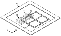
- FIG. 1 is a schematic structural diagram of a digital microfluidic device according to an exemplary embodiment of the present disclosure
- FIGS. 2a to 2c are structural schematic diagrams of a digital microfluidic chip according to an embodiment of the present disclosure
- FIG. 3 is a schematic structural diagram of another digital microfluidic chip according to an embodiment of the present disclosure.
- FIG. 4 is a schematic structural diagram of another digital microfluidic chip according to an embodiment of the present disclosure.
- FIG. 5 is a schematic structural diagram of another digital microfluidic chip according to an embodiment of the present disclosure.
- FIG. 6a to 6b are structural schematic diagrams of a thermal control device according to an embodiment of the present disclosure.
- FIG. 7 is a schematic structural diagram of an elastic support device according to an embodiment of the present disclosure.
- FIG. 8 is a schematic structural view of a cover plate according to an embodiment of the present disclosure.
- FIG. 9 is a schematic structural diagram of another digital microfluidic device according to an embodiment of the present disclosure.
- 10a to 10c are schematic diagrams of the temperature distribution in the hot zone of the embodiment of the present disclosure.
- FIG. 11 is a diagram of the repeatability test results of the hot zone according to the embodiment of the present disclosure.
- FIG. 12a to 12b are schematic structural views of another elastic support device according to an embodiment of the present disclosure.
- FIG. 13 is a schematic diagram of a three-dimensional structure of another digital microfluidic device according to an embodiment of the present disclosure.
- FIG. 14 is a schematic diagram of the appearance of a digital microfluidic device according to an embodiment of the present disclosure.
- 70 temperature controller
- 80 input and output device
- 90 droplet
- 111 the first electrode layer
- 112 the first protective layer
- 113 the first lyophobic layer
- connection should be interpreted in a broad sense.
- it may be a fixed connection, or a detachable connection, or an integral connection; it may be a mechanical connection, or an electrical connection; it may be a direct connection, or an indirect connection through an intermediate piece, or an internal communication between two components.
- parallel refers to a state where the angle formed by two straight lines is -10° to 10°, and therefore includes a state where the angle is -5° to 5°.
- perpendicular means a state in which the angle formed by two straight lines is 80° to 100°, and therefore also includes an angle of 85° to 95°.
- triangle, rectangle, trapezoid, pentagon, or hexagon in this specification are not strictly defined, and may be approximate triangles, rectangles, trapezoids, pentagons, or hexagons, etc., and there may be some small deformations caused by tolerances. There can be chamfers, arc edges, deformations, etc.
- the digital microfluidic chip uses the principle of electrowetting (Electrowetting on Dielectric, referred to as EWOD) to place droplets on the surface with a hydrophobic layer. With the help of electrowetting effect, the droplet is changed by applying a voltage to the droplet. The wettability with the hydrophobic layer causes a pressure difference and asymmetric deformation inside the droplet, thereby realizing the directional movement of the droplet.
- Digital microfluidics is divided into active digital microfluidics and passive digital microfluidics. The main difference between the two is that active digital microfluidics drives droplets in an array, which can precisely control the liquid at a certain position. Droplets move individually, whereas in passive digital microfluidics the droplets move or stop together in all positions.
- PCR reactions involve a variety of reaction temperatures.
- the PCR reaction can include the following three basic reaction steps: (1) DNA denaturation (90°C to 96°C), the double-stranded DNA template is under the action of heat, and the hydrogen bond is broken to form single-stranded DNA; (2) annealing (60°C) °C to 65°C), the temperature of the system decreases, and the primers combine with the DNA template to form a partial double strand; (3) extension (70°C to 75°C), under the action of Taq enzyme (at about 72°C, the activity is the best) , using dNTP as a raw material, starting from the 3' end of the primer and extending in the direction from 5' ⁇ 3' end to synthesize a DNA strand complementary to the template. After one cycle of denaturation, annealing and extension, the DNA content doubles, and most PCR reactions can include 25 to 35 cycles. Studies have shown that the temperature change rate of cycling between multiple reaction temperatures is critical to the overall PCR reaction efficiency
- the inventors of the present application found that the existing digital microfluidic devices used in PCR reactions have problems such as slow temperature change rate, large temperature change overshoot, complex structure and large volume. Since the existing digital microfluidic device realizes the cyclic switching of the reaction temperature by circulating the heating and cooling in a micro-reaction tank, it is limited by the heating rate and cooling rate of the temperature-changing system, so the temperature-changing rate is relatively slow, and the maximum temperature-changing rate can only reach 8°C/s. In addition, due to frequent heating and cooling, temperature control needs to introduce a temperature overshoot (about 3°C). Not only does it take a long time for the overshoot to return to stability, but there is also a risk of affecting the enzyme activity. Further, since the temperature-variable system adopts structures such as semiconductor cooling fins, heat sinks, and fans, the device has complex structure, large volume, and high cost.
- FIG. 1 is a schematic structural diagram of a digital microfluidic device according to an exemplary embodiment of the present disclosure.
- the digital microfluidic device may include a digital microfluidic chip 10 , a thermal control device 20 and an elastic support device 30 .
- the digital microfluidic chip 10 may be provided with a droplet channel configured for the liquid droplets 90 to move therebetween.
- the thermal control device 20 is arranged on one side of the digital microfluidic chip 10 and is configured to generate at least two independent and non-interfering thermal zones in the droplet channel, and control the temperature of each thermal zone.
- the elastic supporting device 30 is arranged on the side of the thermal control device 20 away from the digital microfluidic chip 10 , and is configured to drive the thermal control device 20 to be pasted on the surface of the digital microfluidic chip 10 .
- the digital microfluidic chip 10 may include a first substrate 11 and a second substrate 12 oppositely arranged, and the first substrate 11 and the second substrate 12 may be connected by a sealant 13, so that the first substrate 11.
- the second substrate 12 and the sealant 13 form a cavity with a suitable gap, and the droplets 90 of polar materials (aqueous and/or ionic) are confined between the first substrate 11 and the second substrate 12 in plane.
- a plurality of spacers may be disposed between the first substrate 11 and the second substrate 12 , and the plurality of spacers may form a droplet channel.
- a driving electrode may be disposed on the first substrate 11 and a reference electrode may be disposed on the second substrate 12 , the driving electrodes and the reference electrodes are configured to drive the liquid droplet 90 to move in the liquid droplet channel.
- the digital microfluidic chip 10 may include a liquid inlet 14 configured to input fluid into a droplet channel.
- the thermal control device 20 may be disposed on a side of the first substrate 11 away from the second substrate 12 , and driven by the elastic support device 30 to be pressed onto the surface of the side.
- the thermal control device 20 may at least include a first thermal control element, a second thermal control element, and a third thermal control element, and the first thermal control element is configured as a droplet on the digital microfluidic chip 10 A first thermal area is generated in the channel, and the first thermal area is controlled to have a first temperature, and the second thermal control element is configured to generate a second thermal area in the droplet channel of the digital microfluidic chip 10, and control the second thermal area.
- the zone has a second temperature
- the third thermal control element is configured to generate a third thermal zone in the droplet channel of the digital microfluidic chip 10, and controls the third thermal zone to have a third temperature, in the digital microfluidic chip 10
- Three independent and non-interfering thermal zones are formed on the digital microfluidic chip, that is, the three thermal zones on the digital microfluidic chip are created and controlled by the thermal control device.
- the elastic support device 30 may include a support frame and an elastic element, the support frame may be arranged on the side of the thermal control device 20 away from the digital microfluidic chip 10, and the elastic element may be arranged on the support frame and the thermal control device. Between 20 , the elastic element is configured to exert an elastic force on the thermal control device 20 , so that the thermal control device 20 is pressed onto the surface of the digital microfluidic chip 10 .
- the digital microfluidic chip 10 can drive the droplet 90 to move from the first thermal zone to the second thermal zone, so that the temperature of the droplet 90 rapidly changes from the first temperature T1 to the second temperature T2, or the digital The microfluidic chip 10 can drive the droplet 90 to move from the second thermal zone to the third thermal zone, so that the temperature of the droplet 90 changes rapidly from the second temperature T2 to the third temperature T3, and the temperature change rate can be greater than or equal to 12°C/s .
- the exemplary embodiment of the present disclosure sets multiple thermal zones, and the liquid droplets can move rapidly between multiple thermal zones, so that the digital microfluidic device of the exemplary embodiment of the present disclosure can be applied to implement any need to change the temperature of the liquid droplets to Multiple temperatures in a lab-on-a-chip as part of a droplet manipulation scheme.
- FIG. 2a to 2c are schematic structural diagrams of a digital microfluidic chip according to an exemplary embodiment of the present disclosure
- FIG. 2a is a schematic diagram of a three-dimensional structure of a digital microfluidic chip
- FIG. 2b is a schematic diagram of a planar structure of a digital microfluidic chip
- 2c is a schematic diagram of the cross-sectional structure of the digital microfluidic chip.
- a droplet channel 91 is provided on the digital microfluidic chip 10 , and the droplet channel 91 is configured for the liquid droplet 90 to move therebetween.
- the droplet channel 91 may include at least one first channel 91-1 extending along the first direction X and at least one second channel 91-2 extending along the second direction Y, the first channel 91-1 and the second channel 91-2 communicate with each other to form a grid, and the first direction X and the second direction Y intersect.
- the thermal control device located on the lower side of the digital microfluidic chip 10 forms three independent and non-interfering thermal zones on the droplet channel 91, the three thermal zones are respectively the first thermal zone 51, A second thermal zone 52 and a third thermal zone 53 .
- the shape of the three thermal zones may be a rectangle.
- the digital microfluidic chip 10 may include a first substrate 11 and a second substrate 12 oppositely arranged.
- the first substrate 11 may include a first base 110, a first electrode layer 111 disposed on the side of the first base 110 close to the second substrate 12, and a first protective layer disposed on the side of the first electrode layer 111 close to the second substrate 12.
- 112 and the first lyophobic layer 113 disposed on the side of the first protective layer 112 close to the second substrate 12 .
- the second substrate 12 may include a second base 120, a second electrode layer 121 disposed on the side of the second base 120 close to the first substrate 11, and a second protective layer disposed on the side of the second electrode layer 121 close to the first substrate 11. 122 and the second lyophobic layer 123 disposed on the side of the second protective layer 122 close to the first substrate 11 .
- the first electrode layer 111 may include a plurality of first electrodes arranged at intervals corresponding to the droplet channel and configured to drive the droplet to move in the droplet channel.
- the material of the first electrode layer 111 can be a metal material, such as silver (Ag), copper (Cu), aluminum (Al) or molybdenum (Mo), or an alloy material composed of metal, such as aluminum neodymium alloy (AlNd ) or molybdenum-niobium alloy (MoNb), etc.
- the alloy material can be a single-layer structure, or it can be a multi-layer composite structure, such as a composite structure composed of Mo layer, Cu layer and Mo layer.
- the first protective layer 112 covers the first electrode layer 111 and has good insulation.
- the material of the first protective layer 112 can be an insulating material, such as resin, polyimide (PI), silicon oxide (SiOx), silicon nitride Compound (SiNx) or silicon oxynitride (SiON), etc., can be a single-layer structure, or can be a multi-layer composite structure.
- the first lyophobic layer 113 has good lyophobicity, and when in direct contact with the droplet 90 , the droplet 90 has a relatively high surface tension. The contact angle between the droplet 90 and the first lyophobic layer 113 is the initial contact angle.
- the first lyophobic layer 113 at the corresponding position of the first electrode accumulates charges, thereby changing the first lyophobic layer 113.
- the wetting property between the layer 113 and the droplet 90 attached to the surface of the first lyophobic layer 113 changes the contact angle between the droplet 90 and the first lyophobic layer 113, thereby causing the droplet 90 to deform, A pressure difference is generated inside the droplet 90, thereby realizing the manipulation of the droplet 90.
- the material of the first lyophobic layer 113 can be Teflon, perfluororesin (CYTOP) and other fluoropolymers.
- the droplet 90 can be set to be in direct contact with the first protective layer 112, and the first substrate 11 can include a first base 110, a first electrode layer 111 and the first protective layer 112. If the first lyophobic layer 113 has good insulation, the first lyophobic layer 113 can be set to directly cover the first electrode layer 111, and the first substrate 11 can include the first base 110, the first electrode layer 111 and the first lyophobic layer 111.
- the liquid layer 113 is not limited in this disclosure.
- the second electrode layer 121 may include a reference electrode configured to apply a reference potential to provide a reference voltage to a plurality of first electrodes, so that there is a large gap between the first electrodes and the reference electrodes. The voltage difference can form a larger driving voltage to control the movement of the droplet 90 .
- the reference electrode may be a surface electrode, and an orthographic projection of the surface electrode on the first substrate includes a plurality of orthographic projections of the first electrodes on the first substrate.
- the reference electrode may be a plurality of strip electrodes.
- the strip-shaped reference electrodes may be in the shape of strips extending along the first direction X, and the orthographic projection of each strip-shaped reference electrode on the first substrate includes a plurality of sequentially arranged in the first direction X An orthographic projection of the first electrode on the first substrate.
- the material of the second electrode layer 121 can be a metal material, such as silver (Ag), copper (Cu), aluminum (Al) or molybdenum (Mo), or an alloy material composed of metal, such as aluminum neodymium alloy (AlNd).
- the alloy material can be a single-layer structure, or it can be a multi-layer composite structure, such as a composite structure composed of Mo layer, Cu layer and Mo layer.
- the second protective layer 122 covering the second electrode layer 121 has good insulation
- the material of the second protective layer 122 can be an insulating material, such as resin, polyimide (PI), silicon oxide (SiOx), silicon nitride (SiNx), or silicon oxynitride (SiON), etc., may be a single-layer structure, or may be a multi-layer composite structure.
- the second lyophobic layer 123 has good lyophobicity, and when in direct contact with the liquid droplet 90 , the liquid droplet 90 has a relatively high surface tension.
- the material of the second lyophobic layer 123 can be Teflon, perfluororesin (CYTOP) and other fluoropolymers.
- the droplet 90 can be set to be in direct contact with the second protective layer 122, and the first substrate 11 can include a second base 120, a second electrode layer 121 and the second protective layer 122. If the second lyophobic layer 123 has good insulation, the second lyophobic layer 123 can be set to directly cover the second electrode layer 121.
- the second substrate 12 can include a second base 120, a second electrode layer 121 and a second lyophobic layer 121.
- the layer 123 is not limited in this disclosure.
- the shape of the first electrode can be any one or more of the following: square, rectangle, rhombus, trapezoid, polygon, circle, and ellipse.
- the arrangement of an electrode can be any one or more of the following: a straight line arranged along the first direction X or the second direction Y, a cross shape or a T shape arranged along the first direction X and the second direction Y Or X shape, etc., can be determined according to the function of manipulating the liquid droplet, which is not limited in this disclosure.
- the area other than the droplet channel 91 on the digital microfluidic chip 10 may include a plurality of virtual units, and the corresponding first electrodes and reference electrodes may be set at the positions of the virtual units, but there is no mechanism for manipulating the droplets. Function.
- the digital microfluidic chip 10 may be a single substrate, for example, only include the first substrate, or only include the second substrate, which is not limited in this disclosure.
- the digital microfluidic chip provided by the exemplary embodiment of the present disclosure is based on the voltage generated by the electrodes, combined with the lyophobicity between the lyophobic layer and the droplet, and based on the dielectric wetting effect to manipulate the droplet, thereby realizing the Move in the droplet channel.
- the first thermal zone 51, the second thermal zone 52 and the third thermal zone 53 can be arranged in sequence along the first direction X, and the first electrode corresponding to the center point of the first thermal zone 51
- M electrodes can be arranged between the first electrodes corresponding to the central point of the second thermal zone 52, the first electrode corresponding to the central point of the second thermal zone 52 and the first electrode corresponding to the central point of the third thermal zone 53.
- N electrodes can be arranged between one electrode.
- M, N may be about 5 to 15 in number.
- M and N may be about 8.
- the droplet 90 when the droplet 90 moves from the center point of the first thermal zone 51 to the center point of the second thermal zone 52, the droplet 90 will pass through the nine first electrodes. In an exemplary embodiment, it takes about 0.2s for the droplet 90 to pass through one first electrode, and about 1.8s to pass through nine first electrodes.
- the temperature change rate of the droplet 90 is about 12.8°C/s, which is far greater than the maximum temperature change rate of the existing structure.
- the first thermal zone, the second thermal zone, and the third thermal zone may be arranged sequentially in a manner of increasing temperature or decreasing temperature, so as to reduce temperature crosstalk between temperature ranges.
- the first temperature T1 of the first thermal zone may be about 95°C ⁇ 1°C
- the second temperature T2 of the second thermal zone may be about 72°C ⁇ 1°C
- the third temperature of the third thermal zone may be about 95°C ⁇ 1°C.
- the temperature T3 may be about 60°C ⁇ 1°C.
- the shape of the thermal zones is similar to that of the thermal control elements.
- the thermal zone formed on the digital microfluidic chip 10 is basically square or rectangular.
- the thermal zone formed on the digital microfluidic chip 10 is basically circular or elliptical.
- Fig. 4 is a schematic structural diagram of another digital microfluidic chip according to an exemplary embodiment of the present disclosure.
- the structure of the digital microfluidic chip of this exemplary embodiment is basically the same as that of the foregoing embodiments, except that two hot zones are formed on the digital microfluidic chip 10, as shown in FIG. 4 Show.
- the annealing treatment and the extension treatment can be performed in one hot zone, and the annealing and extension are combined into one step (such as 60° C.), that is, two-step PCR.
- the two-step PCR method eliminates the need to switch between annealing and extension, thereby reducing the time required for PCR.
- two hot zones can be formed on the digital microfluidic chip 10 to drive the liquid droplets to circulate in the two temperature zones to realize the reaction.
- Fig. 5 is a schematic structural diagram of another digital microfluidic chip according to an exemplary embodiment of the present disclosure.
- the structure of the digital microfluidic chip of this exemplary embodiment is basically the same as that of the preceding embodiments, the difference is that three droplet channels 91 for performing biochemical reactions are arranged on the digital microfluidic chip, The thermal zones of the same temperature in the three droplet channels 91 are generated by one thermal control element, so that each thermal zone can cover three droplet channels.
- the droplets 90 in each droplet channel can circulate in three thermal zones according to the corresponding driving sequence, and can simultaneously complete multi-channel biochemical reactions, as shown in FIG. 5 .
- FIG. 6a to 6b are schematic structural diagrams of a thermal control device according to an exemplary embodiment of the present disclosure
- FIG. 6a is a schematic three-dimensional structural diagram of the thermal control device
- FIG. 6b is an exploded schematic diagram of the thermal control device.
- the thermal control device 20 may include a support body 21 and a plurality of thermal control bodies 22, the support body 21 is configured to carry a plurality of thermal control bodies 22, and the plurality of thermal control bodies 22
- the bodies 22 are respectively arranged in the support bodies 21 and are configured to respectively form a plurality of hot zones on the digital microfluidic chip.
- the support body 21 may be in the shape of a cuboid, and a plurality of grooves 210 are opened on one side of the support body 21 in the third direction Z (the side facing the digital microfluidic chip), and the plurality of grooves 210 are configured
- the third direction Z may be perpendicular to the plane of the digital microfluidic chip.
- the plurality of grooves 210 may be sequentially disposed along the first direction X, and the minimum distance between adjacent grooves 210 may be about 0.1 mm to 4 mm.
- the shape of the groove 210 may be any one or more of the following: square, rectangle, circle and ellipse.
- the side length of the groove 210 may be used as the characteristic length of the groove, which may be greater than 3 times the droplet diameter.
- the side length of the groove 210 may be about 10mm.
- the groove 210 in the shape of a rectangle the long side of the rectangle extends along the first direction X, and the long side of the groove 210 can be used as the characteristic length of the groove, which can be greater than 3 times the droplet diameter.
- the diameter of the groove 210 can be used as the characteristic length of the groove, which can be greater than 3 times the diameter of the droplet.
- the long axis of the ellipse extends along the first direction X, and the long axis of the groove 210 can be used as the characteristic length of the groove, which can be greater than 3 times the droplet diameter.
- the support body 21 can be made of a material with good heat insulation performance and heat resistance performance, such as bakelite, acrylic and the like.
- the shape of the thermal control body 22 in a plane parallel to the digital microfluidic chip, can be basically the same as the shape of the groove 210, which can be any one or more of the following: square, rectangular, Round and oval.
- the size of the thermal control body 22 may be slightly smaller than the size of the groove 210 where it is located.
- the side length of the square can be used as the characteristic length of the thermal control body, which can be greater than 3 times the diameter of the droplet.
- the side length of the thermal control body 22 may be about 10 mm.
- the thermal control body 22 in the shape of a rectangle the long side of the rectangle extends along the first direction X, and the long side can be used as the characteristic length of the thermal control body, which can be greater than 3 times the diameter of the droplet.
- each thermal control body 22 may include a stacked heat source body 23 and a heat transfer body 24, the heat source body 23 is disposed in the groove 210, and is configured to provide a heat source, and the heat transfer body 24 is disposed on the heat source
- One side of the body 23 in the third direction Z is configured to conduct heat from the heat source body 23 to form multiple heat zones on the digital microfluidic chip.
- the sum of the thicknesses of the heat source body 23 and the heat transfer body 24 may be greater than the depth of the groove 210, so that part of the heat transfer body 24 protrudes from the groove 210, that is, the third direction X of the heat transfer body 24
- the surface on one side is higher than the surface on one side in the third direction X of the support body 21 .
- the depth of the groove, the thickness of the heat source body and the thickness of the heat transfer body are all dimensions in the third direction Z.
- the difference between the sum of the thicknesses of the heat source body and the heat transfer body and the depth of the groove may be about 0.5 mm to 2 mm.
- the heat transfer body 24 can be made of a material with good thermal conductivity, such as aluminum or copper, and the heat transfer body 24 is directly connected to the surface of the first substrate in the digital microfluidic chip away from the second substrate. contact, the heat generated by the heat source body 23 is evenly transferred to the digital microfluidic chip, and a hot zone is formed on the digital microfluidic chip.
- At least one first through hole 220 may be provided on one side of the support body 21 in the second direction Y or in the opposite direction of the second direction Y, and at least one first through hole 220 may be provided in at least An area where a groove 210 is located and runs through the sidewall of the groove 210 .
- At least one sensor hole 241 may be provided on one side of the second direction Y of at least one heat transfer body 24 or on the side opposite to the second direction Y, and the sensor hole 241 is configured to install a fixed temperature sensor 50 .
- the sensor hole 241 may be a blind hole.
- the positions of the first through hole 220 and the sensor hole 241 correspond, and the first through hole 220 and the sensor hole 241 communicate, so that the temperature sensor 50 can pass through the first through hole 220 is inserted into the sensor hole 241.
- the temperature sensor 50 is configured to sense the temperature of the heat transfer body 24 .
- the temperature sensor 50 can include a sensing head and a sensing rod, and the sensing head can be disc-shaped, and a temperature sensing element is arranged therein, such as an NTC thermistor, a PTC thermistor, a platinum resistor, a thermocouple, etc.
- the head can be arranged at the end of the sensing rod, so that the sensing head can protrude into the inside of the heat transfer block, such as the central area of the heat transfer block, to sense the temperature inside the heat transfer body 24 .
- the sensor hole 241 may be filled with silica gel or silicone grease with good thermal conductivity to fix the temperature sensor 50 .
- At least one second through hole 230 may be provided on one side of the support body 21 in the second direction Y or in the opposite direction of the second direction Y, and at least one second through hole 230 may be provided in at least An area where a groove 210 is located and runs through the sidewall of the groove 210 .
- At least one connection hole 231 may be provided on one side of at least one heat source body 23 in the second direction Y or on the side opposite to the second direction Y, and the connection hole 231 is configured to install a fixing connector 232 .
- the connection hole 231 may be a blind hole.
- the positions of the second through hole 230 and the connecting hole 231 are corresponding, and the second through hole 230 and the connecting hole 231 are communicated, so that the connecting piece 232 can pass through the second through hole 230 inserted into the connection hole 231.
- the heat source body 23 can be a ceramic heating plate, which has the advantages of good thermal conductivity, uniform heating, good thermal insulation performance, corrosion resistance, and long service life.
- the connecting piece 232 can be rod-shaped, one end is connected to the power source, and the other end is electrically connected to the heat source body 23 by being inserted in the connecting hole 231 .
- Fig. 7 is a schematic structural diagram of an elastic support device according to an exemplary embodiment of the present disclosure.
- the elastic support device 30 may include a support frame 31 and an elastic element 32, the end of the elastic element 32 away from the digital microfluidic chip 10 is connected to the support frame 31, and the elastic element 32 is close to the digital microfluidic chip 10.
- One end of the microfluidic chip 10 is connected to the thermal control device 20 , and the elastic element 32 is configured to apply elastic force to the thermal control device 20 so that the thermal control device 20 is attached on the surface of the digital microfluidic chip 10 .
- the support frame 31 may include a bottom frame 311 , a side frame 312 and a top frame 313 .
- the bottom frame 311 can be a plate-shaped structure
- the top frame 313 can be a plate-shaped structure with a first opening 33 in the middle
- the side frame 312 can be a cylindrical structure
- the first end of the side frame 312 is connected to the outer edge of the bottom frame 311
- the second end of the side frame 312 is connected to the outer edge of the top frame 313, so that the bottom frame 311, the side frame 312 and the top frame 313 enclose a first accommodating cavity 34 where the elastic element 32 and the thermal control device 20 can be arranged
- the first opening 33 communicates with the first accommodating cavity 34 .
- one end of the elastic element 32 is connected to the bottom frame 311, and the other end of the elastic element 32 is connected to the surface of the thermal control device 20 near the bottom frame 311, and the thermal control device 20 elastically supported by the elastic element 32 Among them, the side close to the elastic element 32 is arranged in the first accommodating cavity 34, and the side away from the elastic element 32 protrudes from the first opening 33, that is, the surface of the thermal control device 20 on the side away from the bottom frame 311 and the bottom frame The distance between 311 is greater than the distance between the surface of the top frame 313 away from the bottom frame 311 and the bottom frame 311 .
- the elastic element 32 may be 3 to 6 springs, and the 3 to 6 springs are respectively connected to the bottom frame 311 and the thermal control device 20 .
- the length of the springs is L1.
- Fig. 8 is a schematic structural diagram of a cover plate according to an exemplary embodiment of the present disclosure.
- the digital microfluidic device may further include a cover frame 40
- the cover frame 40 may include a front frame 41 and a frame 42 .
- the front frame 41 can be a plate structure with a second opening 43 in the middle
- the frame 42 can be a cylindrical structure
- the first end of the frame 42 is connected to the top frame 313 of the support frame 31
- the second end of the frame 42 is connected to the front frame.
- the front frame 41 and frame 42 in the cover frame 40 and the top frame 313 in the support frame 31 enclose a second accommodating chamber 44 in which the digital microfluidic chip 10 can be set, and the first opening 33 and the second opening 43 communicate with the second accommodating cavity 44 respectively.
- the assembly process of the digital microfluidic device of the exemplary embodiment of the present disclosure may include: after connecting the lower side of the thermal control device 20 with the elastic element 32 in the elastic support device 30, and then connecting the digital microfluidic
- the control chip 10 is arranged on the upper side of the thermal control device 20, and then the front frame 41 of the cover frame 40 is pressed onto the digital microfluidic chip 10, and the frame 42 of the cover frame 40 is connected to the top frame 313 of the support frame 31 by applying pressure. contact, the cover frame 40 and the support frame 31 are fixed through the connecting piece, and the digital microfluidic chip 10 is fixed in the second accommodating cavity 44 defined between the cover frame 40 and the support frame 31 .
- the elastic element 32 is compressed, and the elastic force of the elastic element 32 acts on the thermal control device 20, so that the plurality of heat transfer bodies 24 of the thermal control device 20 are in close contact with the lower surface of the digital microfluidic chip 10 , can realize uniform transfer of heat, and form multiple hot zones on the digital microfluidic chip 10 .
- a spring is used for the elastic element 32 , and after the cover frame 40 is fixed to the support frame 31 (that is, after the digital microfluidic chip is loaded), the length of the spring is L2.
- the compression distance L1-L2 of the spring can be set to be about 1 mm to 3 mm, which can not only ensure that the thermal control device 20 is in close contact with the digital microfluidic chip 10, but also ensure that the spring has a certain elastic force to achieve thermal stability of multiple crimping and thermal repeatability.
- FIG. 9 is a schematic structural diagram of another digital microfluidic device according to an exemplary embodiment of the present disclosure.
- a digital microfluidic device may include a digital microfluidic chip 10, a thermal control device 20, an elastic support device 30, a cover frame 40, a temperature sensor 50, a calibration sensor 60, a temperature
- the structures of the controller 70 and the input and output device 80 , the digital microfluidic chip 10 , the thermal control device 20 , the elastic support device 30 and the cover frame 40 are basically the same as those of the previous embodiments, and will not be repeated here.
- the temperature controller 70 is respectively connected to the connection piece 232 inserted in the heat source body 23, the temperature sensor 50 inserted in the heat transfer body 24, and the calibration sensor arranged inside the digital microfluidic chip 10. 60 connection, the temperature controller 70 is configured to obtain the correction value in the calibration stage, obtain the temperature of the heat transfer body collected by the temperature controller 70 in the test stage, and control the heating of the heat source body 23 through the connection part 232 according to the temperature of the heat transfer body and the correction value quantity.
- a plurality of calibration sensors 60 may be arranged inside the digital microfluidic chip 10 and configured to collect the temperature in the digital microfluidic chip 10. After the calibration is completed, the calibration sensors 60 Removed from the digital microfluidic chip 10.
- a plurality of calibration sensors 60 can be respectively arranged in the center of a plurality of preset thermal zones in the digital microfluidic chip 10, and the temperature of each thermal zone can be collected at multiple temperature points. .
- the temperature controller 70 acquires the temperature of the heat transfer body collected by the temperature sensor 50 and the temperature of the hot zone collected by the correction sensor 60 , the difference between the temperature of the heat transfer body and the temperature of the hot zone can be obtained, and the difference can be used as a correction value.
- the temperature of the heat transfer body collected by the temperature controller 70 minus the correction value can be used as the temperature value of the thermal zone in the digital microfluidic chip 10 .
- the calibration sensor 60 can be NTC thermistor, PTC thermistor, platinum resistance thermometer, thermocouple, etc., and the size of the calibration sensor 60 should be smaller than the box thickness of the digital microfluidic chip 10 .
- the temperature controller 70 obtains the temperature of the heat transfer body collected by the temperature sensor 50 and the temperature of the hot zone collected by the correction sensor 60 respectively, and obtains the temperature of the heat transfer body and the temperature of the hot zone at each temperature point The difference is used as the correction value and stored.
- the temperature controller 70 controls the working voltage of the heating body and the heating amount of the heat source body according to the collected temperature of the heat transfer body and the pre-stored correction value, so as to realize the temperature control function.
- the input and output device 80 is communicatively connected with the temperature controller 70, and the input and output 80 is configured to enable the tester to input the set temperature values of multiple thermal zones in the PCR reaction, and send the set temperature values to the temperature controller.
- the controller 70 receives parameters such as temperature and voltage from the temperature controller 70 and displays them in real time.
- the digital microfluidic device may further include a driving circuit connected to the digital microfluidic chip, and the driving circuit is configured to control the operation of the digital microfluidic chip through a driving signal.
- the driving circuit may be provided separately, or may be provided in a temperature controller, or may be provided in an input and output device, which is not limited in this disclosure.
- 10a to 10c are schematic diagrams of the temperature distribution in the hot zone of an exemplary embodiment of the present disclosure, taking a droplet with a diameter of about 3 mm as an example.
- simulation analysis shows that when the side length of the heat transfer block is about 10 mm and the distance between adjacent thermal control bodies (that is, the distance between adjacent heat transfer bodies) is about 3.5 mm, the first The standard deviation of droplet temperature ⁇ in the hot zone is 0.26°C, the standard deviation of droplet temperature in the second hot zone is 0.14°C, the standard deviation of droplet temperature in the third hot zone is 0.10°C, and the standard deviation of droplet temperature in the third hot zone is 0.10°C.
- the maximum value of the temperature standard deviation ⁇ is 0.26 °C, as shown in Fig. 10a. According to the principle of three times standard deviation, 3 ⁇ 1°C. Therefore, when the side length of the heat transfer block is about 10 mm and the distance between them is about 3.5 mm, the temperature of the liquid droplets in the three thermal zones meets the accuracy requirement of ⁇ 1°C. Among them, the droplet temperature standard deviation ⁇ is the finite element simulation result of the internal temperature of the droplet, which is used to characterize the degree of difference in the temperature distribution inside the droplet.
- simulation analysis shows that when the side length of the heat transfer block is about 5 mm and the distance between adjacent thermal control bodies (that is, the distance between adjacent heat transfer bodies) is about 3.5 mm, the first The standard deviation of droplet temperature ⁇ in the hot zone is 0.84°C, the standard deviation of droplet temperature in the second hot zone is 0.45°C, and the standard deviation of droplet temperature in the third hot zone is 0.34°C.
- the maximum value of the temperature standard deviation ⁇ is 0.84 °C, as shown in Fig. 10b. According to the principle of three times standard deviation, 3 ⁇ >1°C. Therefore, when the side length of the heat transfer block is about 5 mm and the distance between them is about 3.5 mm, the temperature of the liquid droplets in the three thermal zones does not meet the accuracy requirement of ⁇ 1°C.
- simulation analysis shows that when the side length of the heat transfer block is about 10 mm and the distance between adjacent thermal control bodies (that is, the distance between adjacent heat transfer bodies) is about 0.1 mm, the first The standard deviation of the droplet temperature ⁇ in the hot zone is 0.28°C, the standard deviation of the droplet temperature in the second hot zone is 0.22°C, the standard deviation of the droplet temperature in the third hot zone is 0.13°C, and the droplet temperature in the three hot zones The maximum value of the temperature standard deviation ⁇ is 0.28 °C, as shown in Fig. 10c. According to the principle of three times standard deviation, 3 ⁇ 1°C. Therefore, when the side length of the heat transfer block is about 10 mm and the distance between them is about 0.1 mm, the temperature of the liquid droplets in the three thermal zones meets the accuracy requirement of ⁇ 1°C.
- the simulation analysis shows that the smaller the side length of the heat transfer block, the larger the standard deviation ⁇ of the droplet temperature, that is, the more uneven the droplet temperature distribution.
- the ratio of the side length of the heat transfer block to the diameter of the droplet is greater than 3 times, the The temperature of the droplet meets the accuracy requirement of ⁇ 1°C.
- the simulation analysis shows that the distance between adjacent heat transfer bodies has no significant effect on the droplet temperature distribution. Therefore, on the premise that the processing is allowed, the distance between the heat transfer blocks can be appropriately reduced to reduce the distance of the liquid droplets moving in the hot zone, and reduce the time-consuming of the liquid droplets moving in the hot zone.
- Fig. 11 is a graph showing the repeatability test results of the hot zone according to the exemplary embodiment of the present disclosure.
- Three digital microfluidic chips were tested in the same thermal control device and elastic support device. The test results show that in the whole workflow of the three digital microfluidic chips, the standard deviation of droplet temperature is less than or equal to 0.06°C, and the maximum error of droplet temperature is 0.48°C (target 72°C, actual measurement 71.52°C), indicating that the system control The temperature stability and repeatability are good, as shown in Figure 11.
- the elastic support device 30 may include an elastic element 32 , a support column 35 and a support base 36 .
- the support base frame 36 can be a plate-shaped structure with a first opening 33 in the middle, the digital microfluidic chip 10 can be arranged on one side of the support base frame 36 in the third direction Z, and the cover frame 40 can be arranged on the digital microfluidic chip.
- the cover frame 40 is connected to the support base frame 36 by a plurality of screws, and the digital microfluidic chip 10 is fixed between the cover frame 40 and the support base frame 36 .
- the elastic element 32 and the support column 35 can be arranged on the side of the support base frame 36 away from the digital microfluidic chip 10, the end of the elastic element 32 away from the digital microfluidic chip 10 is connected to the support column 35, and the elastic element 32 is close to the digital microfluidic chip 10.
- One end of the control chip 10 is connected to the thermal control device 20, and the elastic element 32 is configured to exert elastic force on the thermal control device 20, so that the thermal control device 20 extends into the first opening 33 on the support base 36, and tightly It is pasted on the surface of the digital microfluidic chip 10 .
- the elastic element 32 can be a spring mechanism
- the spring mechanism can include a bottom plate, a top plate, and 3 to 6 springs, and 3 to 6 springs are arranged between the bottom plate and the top plate, and are connected to the bottom plate and the top plate respectively.
- the bottom plate is configured to be connected to the end of the support column 35 on the side close to the digital microfluidic chip 10
- the top plate is configured to be connected to the surface of the thermal control device 20 on the side away from the digital microfluidic chip 10 .
- the supporting column 35 may be a columnar structure, and is connected to the bottom plate of the elastic element 32 through a socket or the like.
- Fig. 13 is a schematic perspective view of another digital microfluidic device according to an exemplary embodiment of the present disclosure.
- the digital microfluidic device may include a digital microfluidic chip 10, a thermal control device, an elastic support device 30, a cover frame 40, a temperature controller, an input and output device 80, and a base frame 100.
- the structures of the chip 10 , the thermal control device, the elastic support device 30 and the cover frame 40 are basically the same as those shown in FIGS. 12 a to 12 b , and will not be repeated here.
- the base frame 100 may include a base frame and a fixed column, the base frame may be a plate structure, the fixed column may be a column structure, one end of the fixed column is connected to the base frame, and the other end of the fixed column is connected to the elastic support
- the support base frame 36 of the device 30 makes the elastic support device 30 fixed on the base frame through the fixing column, and the end of the support column 35 of the elastic support device 30 away from the digital microfluidic chip 10 can be set on the base frame.
- the input and output device 80 may include a touch screen, through which the tester can input the PCR reaction and check the result of the PCR reaction through the touch screen.
- Fig. 14 is a schematic diagram of the appearance of a digital microfluidic device according to an exemplary embodiment of the present disclosure.
- the digital microfluidic device can include a housing, and structures such as a thermal control device, an elastic support device, a cover frame and a base frame are arranged in the housing, and the digital microfluidic chip and the input and output devices are arranged on the housing. , has the advantages of simple appearance, small size and convenient operation.
- the present disclosure forms a plurality of independent and non-interfering thermal zones on the digital microfluidic chip, and the liquid droplets can move back and forth in multiple thermal zones to realize liquid crystallization.
- the rapid temperature change of the droplet, and the temperature change rate is relatively fast. For example, when a droplet moves from the second hot zone with a constant temperature of 72°C to the first hot zone with a constant temperature of 95°C, it takes 1.8s for the droplet to pass through nine first electrodes, and the temperature change rate is 12.8°C/ s, which is far greater than the maximum temperature change rate of the existing structure.
- the digital microfluidic device provided by the present disclosure does not need to frequently control the temperature rise and fall of the heating element, can greatly increase the temperature change rate, and can greatly shorten the temperature change time.
- the digital microfluidic device provided by the present disclosure does not need to use temperature overshoot, which not only further shortens the temperature stabilization time, but also avoids the influence of temperature overshoot on enzyme activity. Since each hot zone of the present disclosure does not require frequent heating and cooling, a natural cooling scheme can be adopted, thus avoiding the use of forced cooling elements such as semiconductor cooling fins, heat sinks, fans, etc., minimizing structural complexity and simplifying It has the advantages of simple structure, small volume and low cost.
- Exemplary embodiments of the present disclosure also provide a driving method of a digital microfluidic device using the aforementioned digital microfluidic device.
- a driving method of a digital microfluidic device may include:
- the first thermal zone has a first temperature for performing a denaturation step, so the second thermal zone has a second temperature at which the extending step is performed, and the third thermal zone has a third temperature at which the annealing step is performed;
- Performing a polymerase chain reaction cycle including: moving the droplet to the first thermal zone to denature nucleic acid; moving the droplet to the third thermal zone to combine primers with nucleic acid templates , forming a partial double strand; moving the droplet to the second hot zone, synthesizing a nucleic acid strand complementary to the template;
- the first temperature T1 of the first thermal zone may be about 95°C ⁇ 1°C
- the second temperature T2 of the second thermal zone may be about 72°C ⁇ 1°C
- the third temperature of the third thermal zone may be about 95°C ⁇ 1°C.
- the temperature T3 may be about 60°C ⁇ 1°C.
- the first thermal zone, the second thermal zone, and the third thermal zone may be arranged sequentially in a manner of increasing temperature or decreasing temperature, so as to reduce temperature crosstalk between temperature ranges.
- judgment processing may also be included before step S1.
- the determination process may include:
- step S1 It is judged whether it is a correction stage, if yes, carry out correction processing, otherwise execute step S1.
- correction processing may include:
- the temperature controller respectively obtains the temperature of the heat transfer body collected by the temperature sensor and the temperature of the hot zone collected by the correction sensor; calculates the difference between the temperature of the heat transfer body and the temperature of the hot zone, and uses the difference as a correction value and store;
- the calibration sensor is removed from the digital microfluidic chip.
- the first calibration sensor can be set at the center of the first thermal area preset in the digital microfluidic chip, and the second calibration sensor can be set at the second thermal zone preset in the digital microfluidic chip.
- the third calibration sensor can be set at the center of the preset third thermal zone in the digital microfluidic chip, so as to collect the temperature of each thermal zone as accurately as possible.
- the thermal control device is respectively provided with a first thermal control body, a second thermal A control body and a third thermal control body, the first thermal control body is configured to form a first thermal zone, the second thermal control body is configured to form a second thermal zone, and the third thermal control body is configured to form a third thermal zone .
- the heat transfer body in the first thermal control body is provided with a first temperature sensor for collecting the temperature of the heat transfer body
- the heat transfer body in the second thermal control body is provided with a second temperature sensor for collecting the temperature of the heat transfer body
- the third The heat transfer body in the thermal control body is provided with a third temperature sensor for collecting the temperature of the heat transfer body.
- the temperature controller is respectively connected with the first calibration sensor, the second calibration sensor, the third calibration sensor, the first temperature sensor, the second temperature sensor and the third temperature sensor, and obtains the data collected by the three temperature sensors respectively.
- the temperature of the three heat transfer bodies and the temperature of the three thermal zones collected by the three calibration sensors, the temperature controller obtains the calibration value of the first thermal zone according to the temperature collected by the first calibration sensor and the first temperature sensor, and the calibration value of the first thermal zone according to the second calibration sensor and the temperature collected by the second temperature sensor to obtain the correction value of the second thermal zone, and obtain the correction value of the third thermal zone according to the temperature collected by the third calibration sensor and the third temperature sensor.
- step S1 may include:
- TW1 T1+TX
- TW1 T1+TX
- the temperature controller controls the heating of the heat source body in the first thermal control body, and obtains the second heat transfer body in real time
- the temperature value of the heat transfer body collected by a temperature sensor is used to control the working voltage according to the collected temperature value of the heat transfer body and the target temperature value TW1, and the heating is stopped when the collected temperature value of the heat transfer body is equal to the target temperature value TW1.
- step S2 may include a pretreatment stage and a treatment stage, and the pretreatment stage may include: the digital microfluidic chip drives the droplet to move to the first thermal zone, and maintains the first thermal zone at 95° C. for 3 minutes, The DNA pre-denaturation is completed, and then the digital microfluidic chip drives the droplets to leave the first thermal zone.
- the processing stage may include: the digital microfluidic chip drives the droplet to move to the first thermal zone, and maintains in the first thermal zone at 95° C. for 0.5 min to complete DNA denaturation. Subsequently, the digital microfluidic chip drives the droplet to move to the third thermal zone, and maintains in the third thermal zone at 60°C for 0.5min to complete the annealing. Subsequently, the digital microfluidic chip drives the droplet to move to the second hot zone, and maintains in the second hot zone at 72°C for 0.5min to complete the extension.
- the repeated execution of the polymerase chain reaction cycle in step S3 is the repeated execution of the processing stage, and the number of cycles may be about 25 to 35 times.
- the temperature, duration, and number of cycles of the hot zone can be changed according to the type of reagent, the length of the DNA fragment, etc., which are not limited in the present disclosure.
- Exemplary embodiments of the present disclosure also provide another method for driving a digital microfluidic device using the aforementioned digital microfluidic device.
- a driving method of a digital microfluidic device may include:
- first thermal zone and second thermal zone are respectively generated on the digital microfluidic chip, the first thermal zone has a first temperature for performing a denaturation step, and the second thermal zone has a the second temperature of the annealing step and the extension step;
- performing a polymerase chain reaction cycle comprising: moving the droplet to the first thermal zone to denature nucleic acid; moving the droplet to the second thermal zone to allow primers to bind to nucleic acid templates to form Partially double-stranded, and synthesize a nucleic acid strand complementary to the template;
- the present disclosure can not only realize the rapid temperature change of the liquid droplets by adopting the method of circulating and reciprocating the liquid droplets in multiple thermal zones, but also the temperature change rate is relatively fast, and the temperature change rate is much larger.
- the maximum temperature change rate of the existing structure The digital microfluidic device provided by the present disclosure does not need to frequently control the temperature rise and fall of the heating element, can greatly increase the temperature change rate, and can greatly shorten the temperature change time.
- the digital microfluidic device provided by the present disclosure does not need to use temperature overshoot, which not only further shortens the temperature stabilization time, but also avoids the influence of temperature overshoot on enzyme activity.
- each hot zone of the present disclosure does not require frequent heating and cooling, a natural cooling scheme can be adopted, thus avoiding the use of forced cooling elements such as semiconductor cooling fins, heat sinks, fans, etc., minimizing structural complexity and maximizing It greatly simplifies the structure, and has the advantages of simple structure, small volume and low cost.
Landscapes
- Chemical & Material Sciences (AREA)
- Health & Medical Sciences (AREA)
- Life Sciences & Earth Sciences (AREA)
- Organic Chemistry (AREA)
- General Health & Medical Sciences (AREA)
- Engineering & Computer Science (AREA)
- Chemical Kinetics & Catalysis (AREA)
- Zoology (AREA)
- Wood Science & Technology (AREA)
- Biochemistry (AREA)
- Bioinformatics & Cheminformatics (AREA)
- Proteomics, Peptides & Aminoacids (AREA)
- Clinical Laboratory Science (AREA)
- Molecular Biology (AREA)
- Analytical Chemistry (AREA)
- Biotechnology (AREA)
- General Engineering & Computer Science (AREA)
- Microbiology (AREA)
- Genetics & Genomics (AREA)
- Dispersion Chemistry (AREA)
- Biophysics (AREA)
- Immunology (AREA)
- Physics & Mathematics (AREA)
- Hematology (AREA)
- Sustainable Development (AREA)
- Medicinal Chemistry (AREA)
- Biomedical Technology (AREA)
- Physical Or Chemical Processes And Apparatus (AREA)
Abstract
Priority Applications (1)
| Application Number | Priority Date | Filing Date | Title |
|---|---|---|---|
| US18/273,558 US20240084369A1 (en) | 2021-07-28 | 2022-07-21 | Digital microfluidic apparatus and driving method therefor |
Applications Claiming Priority (2)
| Application Number | Priority Date | Filing Date | Title |
|---|---|---|---|
| CN202110855985.6 | 2021-07-28 | ||
| CN202110855985.6A CN115672417B (zh) | 2021-07-28 | 2021-07-28 | 数字微流控装置及其驱动方法 |
Publications (1)
| Publication Number | Publication Date |
|---|---|
| WO2023005796A1 true WO2023005796A1 (fr) | 2023-02-02 |
Family
ID=85057694
Family Applications (1)
| Application Number | Title | Priority Date | Filing Date |
|---|---|---|---|
| PCT/CN2022/107069 Ceased WO2023005796A1 (fr) | 2021-07-28 | 2022-07-21 | Appareil microfluidique numérique et son procédé de commande |
Country Status (3)
| Country | Link |
|---|---|
| US (1) | US20240084369A1 (fr) |
| CN (1) | CN115672417B (fr) |
| WO (1) | WO2023005796A1 (fr) |
Families Citing this family (3)
| Publication number | Priority date | Publication date | Assignee | Title |
|---|---|---|---|---|
| CN117339645B (zh) * | 2023-11-22 | 2025-09-23 | 东北林业大学 | 一种便携式颗粒和液滴操控微流控装置及其运行方法和应用 |
| CN117487883B (zh) * | 2023-12-29 | 2024-03-29 | 嘉兴朝云帆生物科技有限公司 | 一种用于核酸分析的微流控检测方法和系统 |
| CN118995371A (zh) * | 2024-08-15 | 2024-11-22 | 逐因生物科技(重庆)有限公司 | 液滴生成系统 |
Citations (6)
| Publication number | Priority date | Publication date | Assignee | Title |
|---|---|---|---|---|
| CN102559488A (zh) * | 2012-01-16 | 2012-07-11 | 福建医科大学 | 集成电化学检测技术的定量pcr微流控芯片一体化装置 |
| CN202415561U (zh) * | 2012-01-16 | 2012-09-05 | 福建医科大学 | 定量pcr微流控芯片装置 |
| CN106861779A (zh) * | 2017-02-20 | 2017-06-20 | 广东工业大学 | 一种分段式微流控芯片控温装置 |
| CN107619781A (zh) * | 2016-07-15 | 2018-01-23 | 中国检验检疫科学研究院 | 一种单反应控温高通量微流控芯片核酸扩增装置 |
| CN111235007A (zh) * | 2020-02-24 | 2020-06-05 | 哈尔滨工业大学 | 一种采用石墨烯加热的液滴数字pcr系统 |
| CN111748466A (zh) * | 2020-05-28 | 2020-10-09 | 湖南工业大学 | 一种基于数字微流控的检测装置及其应用和检测方法 |
Family Cites Families (7)
| Publication number | Priority date | Publication date | Assignee | Title |
|---|---|---|---|---|
| CN102220228A (zh) * | 2011-05-23 | 2011-10-19 | 北京工业大学 | 聚合酶链式反应器及实时光学阵列检测装置 |
| CN102604824A (zh) * | 2012-02-29 | 2012-07-25 | 北京工业大学 | 面向空间的微型微流控实时荧光pcr工作系统 |
| WO2015073689A1 (fr) * | 2013-11-13 | 2015-05-21 | Canon U.S. Life Sciences, Inc. | Systèmes de commande thermique et procédés utilisant des capteurs multiplexés thermiquement protégés |
| JP2015114265A (ja) * | 2013-12-13 | 2015-06-22 | キヤノン株式会社 | マイクロ流体デバイス及びその測定温度の補正方法 |
| EP3160649B1 (fr) * | 2014-06-30 | 2019-12-11 | Bio-Rad Laboratories, Inc. | Pcr activé par contact thermique flottant |
| CN121103450A (zh) * | 2017-05-23 | 2025-12-12 | 上海宜晟生物科技有限公司 | 用于测定的样品温度的快速变化 |
| US10695761B2 (en) * | 2017-05-30 | 2020-06-30 | Sharp Life Science (Eu) Limited | Microfluidic device with multiple temperature zones and enhanced temperature control |
-
2021
- 2021-07-28 CN CN202110855985.6A patent/CN115672417B/zh active Active
-
2022
- 2022-07-21 WO PCT/CN2022/107069 patent/WO2023005796A1/fr not_active Ceased
- 2022-07-21 US US18/273,558 patent/US20240084369A1/en active Pending
Patent Citations (6)
| Publication number | Priority date | Publication date | Assignee | Title |
|---|---|---|---|---|
| CN102559488A (zh) * | 2012-01-16 | 2012-07-11 | 福建医科大学 | 集成电化学检测技术的定量pcr微流控芯片一体化装置 |
| CN202415561U (zh) * | 2012-01-16 | 2012-09-05 | 福建医科大学 | 定量pcr微流控芯片装置 |
| CN107619781A (zh) * | 2016-07-15 | 2018-01-23 | 中国检验检疫科学研究院 | 一种单反应控温高通量微流控芯片核酸扩增装置 |
| CN106861779A (zh) * | 2017-02-20 | 2017-06-20 | 广东工业大学 | 一种分段式微流控芯片控温装置 |
| CN111235007A (zh) * | 2020-02-24 | 2020-06-05 | 哈尔滨工业大学 | 一种采用石墨烯加热的液滴数字pcr系统 |
| CN111748466A (zh) * | 2020-05-28 | 2020-10-09 | 湖南工业大学 | 一种基于数字微流控的检测装置及其应用和检测方法 |
Also Published As
| Publication number | Publication date |
|---|---|
| CN115672417A (zh) | 2023-02-03 |
| US20240084369A1 (en) | 2024-03-14 |
| CN115672417B (zh) | 2026-04-07 |
Similar Documents
| Publication | Publication Date | Title |
|---|---|---|
| WO2023005796A1 (fr) | Appareil microfluidique numérique et son procédé de commande | |
| US10695761B2 (en) | Microfluidic device with multiple temperature zones and enhanced temperature control | |
| US20030008286A1 (en) | Miniaturized multi-chamber thermal cycler for independent thermal multiplexing | |
| CN110205242A (zh) | 一种快速实现数字pcr反应的微流控芯片组件及其应用 | |
| EP1984731B1 (fr) | Dispositif de régulation de la température d'un échantillon biologique et/ou chimique et son procédé d'utilisation | |
| US10471431B2 (en) | Apparatuses, systems and methods for providing scalable thermal cyclers and isolating thermoelectric devices | |
| CN203474810U (zh) | 聚合酶连锁反应装置 | |
| US7223949B2 (en) | Analysis apparatus having improved temperature control unit | |
| US20210060556A1 (en) | Chip for polymerase chain reaction, method of operation chip, and reaction device | |
| EA036930B1 (ru) | Устройство термоуправления и способы применения | |
| JP7595648B2 (ja) | デジタルマイクロ流体デバイスの温度制御 | |
| CN111548927A (zh) | 微流控芯片及微流控pcr仪 | |
| CN106660048B (zh) | 分子分析系统及其应用 | |
| EP1943018A1 (fr) | Thermocycleur a geometrie de porte-echantillons optimisee | |
| CN204143278U (zh) | 实时温控微型样品室 | |
| CN103374510A (zh) | 一种基于低熔点金属液滴的pcr反应装置及其实施方法 | |
| CN216192355U (zh) | Pcr微流控温控装置 | |
| CN119746967B (zh) | 一种基于温度测控的数字微流控malbac装置 | |
| CN1971280B (zh) | 一种透明的温度可程序控制的生物芯片 | |
| WO2010041214A1 (fr) | Dispositif microfluidique intégré | |
| CN120818426A (zh) | 微流控芯片及快速pcr检测系统 | |
| CN118988429A (zh) | 一种能够精准快速控温的微流控芯片 | |
| El-Ali et al. | SU-8 based PCR chip with integrated heaters and thermometer | |
| CN121889216A (zh) | 用于温度循环的热控制装置、用于使用热控制装置来控制温度循环的方法以及用于使用热控制装置来控制样品的温度的系统 | |
| CN103589630B (zh) | 一种聚合酶链反应板 |
Legal Events
| Date | Code | Title | Description |
|---|---|---|---|
| 121 | Ep: the epo has been informed by wipo that ep was designated in this application |
Ref document number: 22848401 Country of ref document: EP Kind code of ref document: A1 |
|
| WWE | Wipo information: entry into national phase |
Ref document number: 18273558 Country of ref document: US |
|
| NENP | Non-entry into the national phase |
Ref country code: DE |
|
| 32PN | Ep: public notification in the ep bulletin as address of the adressee cannot be established |
Free format text: NOTING OF LOSS OF RIGHTS PURSUANT TO RULE 112(1) EPC (EPO FORM 1205A DATED 27/05/2024) |
|
| 122 | Ep: pct application non-entry in european phase |
Ref document number: 22848401 Country of ref document: EP Kind code of ref document: A1 |