WO2022135026A1 - Signal sending method, target sensing method, device and storage medium - Google Patents
Signal sending method, target sensing method, device and storage medium Download PDFInfo
- Publication number
- WO2022135026A1 WO2022135026A1 PCT/CN2021/133503 CN2021133503W WO2022135026A1 WO 2022135026 A1 WO2022135026 A1 WO 2022135026A1 CN 2021133503 W CN2021133503 W CN 2021133503W WO 2022135026 A1 WO2022135026 A1 WO 2022135026A1
- Authority
- WO
- WIPO (PCT)
- Prior art keywords
- main lobe
- sensing signal
- received
- target
- transmit beam
- Prior art date
- Legal status (The legal status is an assumption and is not a legal conclusion. Google has not performed a legal analysis and makes no representation as to the accuracy of the status listed.)
- Ceased
Links
Images




Classifications
-
- H—ELECTRICITY
- H04—ELECTRIC COMMUNICATION TECHNIQUE
- H04B—TRANSMISSION
- H04B7/00—Radio transmission systems, i.e. using radiation field
- H04B7/02—Diversity systems; Multi-antenna system, i.e. transmission or reception using multiple antennas
- H04B7/04—Diversity systems; Multi-antenna system, i.e. transmission or reception using multiple antennas using two or more spaced independent antennas
- H04B7/06—Diversity systems; Multi-antenna system, i.e. transmission or reception using multiple antennas using two or more spaced independent antennas at the transmitting station
- H04B7/0686—Hybrid systems, i.e. switching and simultaneous transmission
- H04B7/0695—Hybrid systems, i.e. switching and simultaneous transmission using beam selection
- H04B7/06952—Selecting one or more beams from a plurality of beams, e.g. beam training, management or sweeping
-
- H—ELECTRICITY
- H04—ELECTRIC COMMUNICATION TECHNIQUE
- H04W—WIRELESS COMMUNICATION NETWORKS
- H04W16/00—Network planning, e.g. coverage or traffic planning tools; Network deployment, e.g. resource partitioning or cells structures
- H04W16/24—Cell structures
- H04W16/28—Cell structures using beam steering
-
- G—PHYSICS
- G01—MEASURING; TESTING
- G01S—RADIO DIRECTION-FINDING; RADIO NAVIGATION; DETERMINING DISTANCE OR VELOCITY BY USE OF RADIO WAVES; LOCATING OR PRESENCE-DETECTING BY USE OF THE REFLECTION OR RERADIATION OF RADIO WAVES; ANALOGOUS ARRANGEMENTS USING OTHER WAVES
- G01S13/00—Systems using the reflection or reradiation of radio waves, e.g. radar systems; Analogous systems using reflection or reradiation of waves whose nature or wavelength is irrelevant or unspecified
- G01S13/02—Systems using reflection of radio waves, e.g. primary radar systems; Analogous systems
- G01S13/06—Systems determining position data of a target
- G01S13/46—Indirect determination of position data
-
- G—PHYSICS
- G01—MEASURING; TESTING
- G01S—RADIO DIRECTION-FINDING; RADIO NAVIGATION; DETERMINING DISTANCE OR VELOCITY BY USE OF RADIO WAVES; LOCATING OR PRESENCE-DETECTING BY USE OF THE REFLECTION OR RERADIATION OF RADIO WAVES; ANALOGOUS ARRANGEMENTS USING OTHER WAVES
- G01S13/00—Systems using the reflection or reradiation of radio waves, e.g. radar systems; Analogous systems using reflection or reradiation of waves whose nature or wavelength is irrelevant or unspecified
- G01S13/86—Combinations of radar systems with non-radar systems, e.g. sonar, direction finder
-
- G—PHYSICS
- G01—MEASURING; TESTING
- G01S—RADIO DIRECTION-FINDING; RADIO NAVIGATION; DETERMINING DISTANCE OR VELOCITY BY USE OF RADIO WAVES; LOCATING OR PRESENCE-DETECTING BY USE OF THE REFLECTION OR RERADIATION OF RADIO WAVES; ANALOGOUS ARRANGEMENTS USING OTHER WAVES
- G01S7/00—Details of systems according to groups G01S13/00, G01S15/00, G01S17/00
- G01S7/003—Transmission of data between radar, sonar or lidar systems and remote stations
- G01S7/006—Transmission of data between radar, sonar or lidar systems and remote stations using shared front-end circuitry, e.g. antennas
-
- H—ELECTRICITY
- H04—ELECTRIC COMMUNICATION TECHNIQUE
- H04B—TRANSMISSION
- H04B7/00—Radio transmission systems, i.e. using radiation field
- H04B7/02—Diversity systems; Multi-antenna system, i.e. transmission or reception using multiple antennas
- H04B7/04—Diversity systems; Multi-antenna system, i.e. transmission or reception using multiple antennas using two or more spaced independent antennas
- H04B7/04013—Intelligent reflective surfaces
-
- G—PHYSICS
- G01—MEASURING; TESTING
- G01S—RADIO DIRECTION-FINDING; RADIO NAVIGATION; DETERMINING DISTANCE OR VELOCITY BY USE OF RADIO WAVES; LOCATING OR PRESENCE-DETECTING BY USE OF THE REFLECTION OR RERADIATION OF RADIO WAVES; ANALOGOUS ARRANGEMENTS USING OTHER WAVES
- G01S13/00—Systems using the reflection or reradiation of radio waves, e.g. radar systems; Analogous systems using reflection or reradiation of waves whose nature or wavelength is irrelevant or unspecified
- G01S13/02—Systems using reflection of radio waves, e.g. primary radar systems; Analogous systems
- G01S13/06—Systems determining position data of a target
- G01S13/46—Indirect determination of position data
- G01S2013/462—Indirect determination of position data using multipath signals
- G01S2013/464—Indirect determination of position data using multipath signals using only the non-line-of-sight signal(s), e.g. to enable survey of scene 'behind' the target only the indirect signal is evaluated
Definitions
- the present disclosure relates to the field of communication technologies and radar, and in particular, to a signal transmission method, a target perception method, a device and a storage medium.
- the sensing signal is transmitted mainly by improving the isolation degree of the transceiver antenna of the sensing signal transmission device, and increasing the isolation degree of the transceiver antenna often leads to an increase in the size of the device.
- Embodiments of the present disclosure provide a signal sending method, a target sensing method, a device, and a storage medium, so as to solve the problem that the size of the device increases.
- An embodiment of the present disclosure provides a signal sending method, including:
- the first device switches the main lobe direction of the transmission beam from the first direction to the second direction, and sends a sensing signal; wherein the second direction is the direction in which the main lobe direction of the transmission beam of the first device is aligned with the second device , the first direction is different from the second direction;
- the first device After sending the sensing signal, the first device switches the main lobe direction of the transmit beam from the second direction to the first direction or the third direction, the third direction is the same as the second direction The directions are different.
- the received signal strength of the second device is higher than the received signal strength of the second device in at least one first state, in In the first state, the main lobe direction of the transmit beam of the second device is a direction other than the second direction, and the received signal strength of the second device is that the second device is directed against the first device. the received signal strength.
- the received signal strength of the second device is lower than that of the second device in at least one second state.
- the main lobe direction of the transmit beam of the second device is a direction other than the first direction or the third direction.
- the receiving signal of the second device The signal strength is the received signal strength of the second device for the first device.
- the second device includes:
- the reflection device has the capability of reflecting signals and the capability of receiving signals.
- the method further includes:
- the first device sends configuration information to the second device, where the configuration information includes at least one of the following:
- the sending resource location of the sensing signal, the waveform information of the sensing signal, the configuration information of the second device, and the configuration information of the second device feeding back the sensing information.
- Embodiments of the present disclosure also provide a target perception method, including:
- the second device receives the sensing signal sent by the first device
- the sensing signal is a sensing signal sent by the first device when the direction of the main lobe of the transmit beam is switched from a first direction to a second direction, where the second direction is the main lobe of the transmit beam of the first device
- the orientation is aligned with the orientation of the second device, the first orientation being different from the second orientation.
- the method further includes:
- the second device reflects the sensing signal
- the second device receives the echo signal generated by the target
- the second device detects the target according to the sensing signal received by the second device and the echo signal received by the second device.
- the second device detects the target according to the sensing signal received by the second device and the echo signal received by the second device, including:
- the second device detects the target according to the sensing signal received by the second device, the echo signal received by the second device, and the reflection coefficient of the second device.
- the second device performs the detection on the target according to the sensing signal received by the second device, the echo signal received by the second device, and the reflection coefficient of the second device. testing, including:
- the second device calculates the sending and receiving response of the second device according to the first receiving variable, the second receiving variable and the reflection coefficient of the second device, and calculates the perception information of the target based on the sending and receiving response, according to The perception information of the target, to detect the target;
- the first receiving variable is a receiving variable of the sensing signal received by the second device
- the second receiving variable is a receiving variable of the echo signal received by the second device.
- the method further includes:
- the second device receives the configuration information sent by the first device, where the configuration information includes at least one of the following:
- the time-frequency resource location of the sensing signal, the waveform information of the sensing signal, the configuration information of the second device, and the configuration information of the second device feeding back the sensing information.
- An embodiment of the present disclosure further provides a device, where the device is a first device, including: a memory, a transceiver, and a processor, wherein:
- a memory for storing a computer program
- a transceiver for sending and receiving data under the control of the processor
- a processor for reading the computer program in the memory and performing the following operations:
- the first device After sending the sensing signal, the first device switches the main lobe direction of the transmit beam from the second direction to the first direction or the third direction, the third direction is the same as the second direction The directions are different.
- the received signal strength of the second device is higher than the received signal strength of the second device in at least one first state, in the In the first state, the main lobe direction of the transmit beam of the second device is a direction other than the second direction, and the received signal strength of the second device is that the second device is directed against the first device. the received signal strength.
- the received signal strength of the second device is lower than that of the second device in at least one second state.
- the main lobe direction of the transmit beam of the second device is a direction other than the first direction or the third direction.
- the receiving signal of the second device The signal strength is the received signal strength of the second device for the first device.
- An embodiment of the present disclosure further provides a device, the device is a second device, including: a memory, a transceiver, and a processor, wherein:
- a memory for storing a computer program
- a transceiver for sending and receiving data under the control of the processor
- a processor for reading the computer program in the memory and performing the following operations:
- the sensing signal is a sensing signal sent by the first device when the direction of the main lobe of the transmit beam is switched from a first direction to a second direction, where the second direction is the main lobe of the transmit beam of the first device
- the orientation is aligned with the orientation of the second device, the first orientation being different from the second orientation.
- the processor further includes:
- the target is detected according to the sensing signal received by the second device and the echo signal received by the second device.
- the detecting the target according to the sensing signal received by the second device and the echo signal received by the second device includes:
- the target is detected according to the sensing signal received by the second device, the echo signal received by the second device, and a reflection coefficient of the second device.
- An embodiment of the present disclosure further provides a device, where the device is a first device, including:
- the first sending unit is configured to switch the main lobe direction of the transmission beam from the first direction to the second direction, and send a sensing signal, wherein the second direction is that the main lobe direction of the transmission beam of the first device is aligned with the first direction. Two directions of the device, the first direction is different from the second direction;
- a switching unit configured to switch the main lobe direction of the transmit beam from the second direction to the first direction or the third direction after sending the sensing signal, the third direction is the same as the second direction
- the directions are different.
- the received signal strength of the second device is higher than the received signal strength of the second device in at least one first state, in the In the first state, the main lobe direction of the transmit beam of the second device is a direction other than the second direction, and the received signal strength of the second device is that the second device is directed against the first device. the received signal strength.
- the received signal strength of the second device is lower than that of the second device in at least one second state.
- the main lobe direction of the transmit beam of the second device is a direction other than the first direction or the third direction.
- the receiving signal of the second device The signal strength is the received signal strength of the second device for the first device.
- An embodiment of the present disclosure further provides a device, where the device is a second device, including:
- a first receiving unit configured to receive a sensing signal sent by the first device
- the sensing signal is a sensing signal sent by the first device when the direction of the main lobe of the transmit beam is switched from a first direction to a second direction, where the second direction is the main lobe of the transmit beam of the first device
- the orientation is aligned with the orientation of the second device, the first orientation being different from the second orientation.
- the device further includes:
- a reflection unit for reflecting the sensing signal
- a second receiving unit configured to receive the echo signal generated by the target
- a detection unit configured to detect the target according to the sensing signal received by the second device and the echo signal received by the second device.
- the detection unit is configured to detect the target according to the sensing signal received by the second device, the echo signal received by the second device, and the reflection coefficient of the second device. test.
- An embodiment of the present disclosure further provides a processor-readable storage medium, where the processor-readable storage medium stores a computer program, and the computer program is used to cause the processor to execute the signal sending method of the embodiment of the present disclosure, or , the computer program is used to cause the processor to execute the target perception method of the embodiment of the present disclosure.
- the first device switches the direction of the main lobe of the transmit beam from the first direction to the second direction, and sends a sensing signal; wherein the second direction is the direction of the main lobe of the transmit beam of the first device. the direction of the second device, the first direction is different from the second direction; after sending the sensing signal, the first device switches the main lobe direction of the transmit beam from the second direction to The first direction or the third direction, the third direction is different from the second direction. Since the sensing signal is sent by switching the direction of the main lobe, it is not necessary to increase the isolation of the transceiver antenna to avoid increasing the size of the device.
- FIG. 1 is a schematic structural diagram of a network architecture to which the present disclosure is applicable;
- FIG. 2 is a schematic diagram of a scenario to which the present disclosure is applicable
- FIG. 3 is a flowchart of a signal sending method provided by an embodiment of the present disclosure.
- FIG. 4 is a schematic diagram of a signal transmission applicable to the implementation of the present disclosure.
- FIG. 5 is a flowchart of a target sensing method provided by an embodiment of the present disclosure.
- FIG. 6 is a schematic diagram of switching time of a beam transmission direction to which the present disclosure is applicable.
- FIG. 7 is a structural diagram of a device provided by an embodiment of the present disclosure.
- FIG. 8 is a structural diagram of another device provided by an embodiment of the present disclosure.
- FIG. 9 is a structural diagram of another device provided by an embodiment of the present disclosure.
- FIG. 10 is a structural diagram of another device provided by an embodiment of the present disclosure.
- FIG. 11 is a structural diagram of another device provided by an embodiment of the present disclosure.
- the term "and/or" describes the association relationship of associated objects, and indicates that there can be three kinds of relationships. For example, A and/or B can indicate that A exists alone, A and B exist at the same time, and B exists alone these three situations.
- the character “/” generally indicates that the associated objects are an "or" relationship.
- the term “plurality” refers to two or more than two, and other quantifiers are similar.
- Embodiments of the present disclosure provide a signal sending method, a target sensing method, a device, and a storage medium, so as to solve the problem that the size of the device increases.
- the method and the device are conceived based on the same application. Since the principles of the method and the device for solving the problem are similar, the implementation of the device and the method can be referred to each other, and the repetition will not be repeated.
- applicable systems may be global system of mobile communication (GSM) system, code division multiple access (CDMA) system, wideband code division multiple access (Wideband Code Division Multiple Access, WCDMA) general packet Wireless service (general packet radio service, GPRS) system, long term evolution (long term evolution, LTE) system, LTE frequency division duplex (frequency division duplex, FDD) system, LTE time division duplex (time division duplex, TDD) system, Long term evolution advanced (LTE-A) system, universal mobile telecommunication system (UMTS), worldwide interoperability for microwave access (WiMAX) system, 5G New Radio (New Radio, NR) system, 6G system, etc.
- GSM global system of mobile communication
- CDMA code division multiple access
- WCDMA Wideband Code Division Multiple Access
- general packet Wireless service general packet Radio service
- GPRS general packet Wireless service
- LTE long term evolution
- LTE long term evolution
- LTE frequency division duplex frequency division duplex
- FDD frequency division duplex
- TDD time division duplex
- FIG. 1 is a schematic structural diagram of a network architecture applicable to the implementation of the present disclosure. As shown in FIG. 1, it includes a first device 11 and a second device 12. The first device 11 may be a network device, and the second device 11 may be a network device. Device 12 may be a target or a reflective device. Further, the above-mentioned network framework further includes a terminal 13, or, when the above-mentioned second device 12 is a reflection device, the above-mentioned network framework, as shown in FIG. 2, also includes a target, and the target may be called a target object or a target object.
- the terminal involved in the embodiments of the present disclosure may be a device that provides voice and/or data connectivity to a user, a handheld device with a wireless connection function, or other processing device connected to a wireless modem.
- the name of the terminal device may be different.
- the terminal device may be called user equipment (User Equipment, UE).
- Wireless terminal equipment can communicate with one or more core networks (Core Network, CN) via a radio access network (Radio Access Network, RAN).
- RAN Radio Access Network
- "telephone) and computers with mobile terminal equipment eg portable, pocket-sized, hand-held, computer-built or vehicle-mounted mobile devices, which exchange language and/or data with the radio access network.
- Wireless terminal equipment may also be referred to as system, subscriber unit, subscriber station, mobile station, mobile station, remote station, access point , a remote terminal device (remote terminal), an access terminal device (access terminal), a user terminal device (user terminal), a user agent (user agent), and a user device (user device), which are not limited in the embodiments of the present disclosure.
- the network device involved in the embodiments of the present disclosure may be a base station, and the base station may include a plurality of cells providing services for the terminal.
- the base station may also be called an access point, or may be a device in the access network that communicates with wireless terminal equipment through one or more sectors on the air interface, or other names.
- the network device can be used to exchange received air frames with Internet Protocol (IP) packets, and act as a router between the wireless terminal device and the rest of the access network, which can include the Internet. Protocol (IP) communication network.
- IP Internet Protocol
- the network devices may also coordinate attribute management for the air interface.
- the network device involved in the embodiments of the present disclosure may be a network device (Base Transceiver Station, BTS) in the Global System for Mobile Communications (GSM) or Code Division Multiple Access (Code Division Multiple Access, CDMA). ), it can also be a network device (NodeB) in Wide-band Code Division Multiple Access (WCDMA), or it can be an evolved network device in a long term evolution (LTE) system (evolutional Node B, eNB or e-NodeB), 5G base station (gNB) in 5G network architecture (next generation system), base station in 6G, or Home evolved Node B (HeNB), relay A node (relay node), a home base station (femto), a pico base station (pico), etc., are not limited in the embodiments of the present disclosure.
- a network device may include a centralized unit (CU) node and a distributed unit (DU) node, and the centralized unit and the distributed unit may also be geographically separated.
- One or more antennas can be used between the network device and the terminal for multiple input multiple output (Multi Input Multi Output, MIMO) transmission, and the MIMO transmission can be single user MIMO (Single User MIMO, SU-MIMO) or multi-user MIMO ( Multiple User MIMO, MU-MIMO).
- MIMO transmission can be 2D-MIMO, 3D-MIMO, FD-MIMO, or massive-MIMO, or diversity transmission, precoding transmission, or beamforming transmission.
- the target may be an object that needs to be perceived, such as a person, a vehicle, etc., and as shown in FIG. 2 , in some scenarios, the distance between the target and the first device 11 may be blocked by an occluder or may not exist cover.
- the reflecting device may be an electronic device having the capability of reflecting signals and the capability of receiving signals, for example, electronic devices such as a large-scale antenna array or a smart metasurface.
- FIG. 3 is a flowchart of a signal sending method provided by an embodiment of the present disclosure. As shown in FIG. 3, the method includes the following steps:
- Step 301 The first device switches the direction of the main lobe of the transmission beam from the first direction to the second direction, and sends a sensing signal; wherein, the second direction is that the main lobe direction of the transmission beam of the first device is aligned with the second direction. the orientation of the device, the first orientation is different from the second orientation;
- Step 302 After sending the sensing signal, the first device switches the main lobe direction of the transmit beam from the second direction to the first direction or the third direction, and the third direction is the same as the other direction.
- the second direction is different.
- the above-mentioned first device switches the direction of the main lobe of the transmitting beam from the first direction to the second direction may be, when the sensing signal needs to be sent, the direction of the main lobe of the transmitting beam is switched from the first direction to the second direction.
- the direction is aimed at the above-mentioned second device to send a sensing signal.
- the first direction is different from the second direction, so that the main lobe direction of the transmit beam is not aligned with the second device before switching to the second direction.
- the communication signal is sent to the terminal. , that is, avoiding the second device to send the communication signal.
- the first device After sending the above sensing signal, the first device switches the main lobe direction of the transmit beam from the second direction to the first direction or the third direction. Also, because the third direction is different from the second direction, this can After the sensing signal is sent, if the direction of the main lobe of the transmitting beam is not aligned with the second device, the second device is avoided.
- the main lobe direction of the transmission beam is not aligned with the second device, so that the first device can send other signals during this period, and it is not necessary to increase the isolation of the transceiver antenna. In order to avoid increasing the size of the device, for example, as shown in FIG.
- the first device sends a communication signal to the terminal during this period.
- it can also be implemented to prevent the signal sent by the transmission beam from affecting the second device during the period when the sensing signal is not sent, so as to improve the accuracy of the second device sensing the target.
- the above-mentioned second direction may be the beam direction 402 shown in FIG. 4
- the above-mentioned first direction or the third direction may be the beam direction shown in FIG. 4 . 401.
- the above-mentioned first device may use the transmit beam as a digital beam.
- the embodiment of the present disclosure is not limited to a digital beam, and may also be other beams capable of beam direction switching.
- the switching of the direction of the main lobe of the transmit beam can be realized by beamforming.
- the received signal strength of the second device is higher than that of the second device in at least one first state
- the received signal strength, in the first state, the main lobe direction of the transmit beam of the second device is a direction other than the second direction, and the received signal strength of the second device is the The received signal strength of the first device.
- the above-mentioned at least one first state can be any state except that the main lobe direction of the transmission beam is the second direction, so that when the main lobe direction of the transmission beam is the second direction, the second device receives the first device's
- the signal strength is the highest, that is, the signal strength of the first device received by the second device when the main lobe direction of the transmit beam is in any other direction is greater, so as to improve the perception effect of the second device on the target.
- the above-mentioned first state may be a partial state except that the main lobe direction of the transmitting beam is the second direction, so that when the main lobe direction of the transmitting beam is the second direction, the signal of the first device received by the second device can be realized.
- the intensity is second or stronger.
- the received signal strength of the second device when the main lobe direction of the transmit beam is the second direction is higher than the received signal strength of the second device when the at least one first state is in the first state, so The perception effect of the second device on the target can be improved.
- the received signal strength of the second device is lower than at least one second state the received signal strength of the second device, in the second state, the main lobe direction of the transmit beam of the second device is a direction other than the first direction or the third direction, the The received signal strength of the second device is the received signal strength of the second device for the first device.
- the at least one first state can be any state except that the main lobe direction of the transmitting beam is the first direction or the third direction, so that when the main lobe direction of the transmitting beam is the first direction or the third direction, the first The signal strength of the first device received by the second device is the smallest, that is, the signal strength of the first device received by the second device is smaller than the signal strength of the first device received by the second device when the main lobe direction of the transmit beam is in any other direction.
- the above-mentioned first state may be a partial state except that the main lobe direction of the transmitting beam is the first direction or the third direction, so that when the main lobe direction of the transmitting beam is the first direction or the third direction, the second device receives the The signal strength of the first device is the second smallest or weaker.
- the received signal strength of the second device is lower than that of the second device when the strength of the received signal is lower than at least one second state. the received signal strength, so as to avoid affecting the perception of the target by the second device.
- the direction of the main lobe of the transmitted beam is the second direction
- the direction of the main lobe of the beam transmitted by the first device is aimed at the second device.
- the main lobe direction of the transmitted beam is the first direction or the third direction
- the main lobe direction of the beam transmitted by the first device is not aligned with the second device, and the side lobe direction is also not aligned with the second device.
- the direction of the beam transmitted by one device minimizes the signal strength of the first device received by the second device to avoid affecting the perception of the target by the second device.
- the second device includes:
- the reflection device has the capability of reflecting signals and the capability of receiving signals.
- the above-mentioned target may be an object or object that needs to be perceived, such as a person, a vehicle and other objects.
- the above-mentioned reflecting device may be an electronic device capable of reflecting signals and receiving signals, such as electronic devices such as large-scale antenna arrays or smart metasurfaces.
- the method further includes:
- the first device sends configuration information to the second device, where the configuration information includes at least one of the following:
- the sending resource location of the sensing signal, the waveform information of the sensing signal, the configuration information of the second device, and the configuration information of the second device feeding back the sensing information.
- the above-mentioned sending resource locations may include time-frequency resource locations
- the waveform information of the sensing signal may include the angle of departure (AoD) of the sensing signal
- the configuration information of the second device may include the behavior configuration information of the second device for target detection
- the second device feeds back the configuration information of the perception information.
- the second device feeds back the configuration information of the perception information.
- the sensing signal may be specially designed so that the second device can relatively easily detect the sensing signal, such as a pseudo-random sequence. It should be noted that, in the embodiment of the present disclosure, the sensing signal is not limited.
- the power of the sensing signal sent by the first device may be pre-power or power defined in the protocol. Further, the power of the sensing signal sent by the first device can make the final received signal-to-noise ratio greater than the preset threshold SNR0 when the sensing signal is reflected by the second device and the target reflects to the second device, which can improve the sensing effect of the second device. .
- the beam main lobe direction and the minimum power direction of the first device are respectively aligned with the second direction.
- the second device detects that the received signal-to-noise ratio of the sensing signal is greater than the preset threshold SNR1 twice, the sensing effect of the second device can be further improved.
- the above-mentioned method provided by the embodiments of the present disclosure may be applied to a macro cell or a micro cell, and there may be no obstruction between the first device and the target.
- the first device switches the direction of the main lobe of the transmit beam from the first direction to the second direction, and sends a sensing signal; wherein the second direction is the direction of the main lobe of the transmit beam of the first device. the direction of the second device, the first direction is different from the second direction; after sending the sensing signal, the first device switches the main lobe direction of the transmit beam from the second direction to The first direction or the third direction, the third direction is different from the second direction. Since the sensing signal is sent by switching the direction of the main lobe, it is not necessary to increase the isolation of the transceiver antenna to avoid increasing the size of the device.
- FIG. 5 is a flowchart of a target sensing method provided by an embodiment of the present disclosure. As shown in FIG. 5, the following steps are included:
- Step 501 the second device receives the sensing signal sent by the first device
- the sensing signal is a sensing signal sent by the first device when the main lobe direction of the transmit beam is switched from the first direction to the second direction; wherein the second direction is the main lobe of the transmit beam of the first device
- the orientation is aligned with the orientation of the second device, the first orientation being different from the second orientation.
- the method further includes:
- the second device reflects the sensing signal
- the second device receives the echo signal generated by the target
- the second device detects the target according to the sensing signal received by the second device and the echo signal received by the second device.
- step 503 receives the above-mentioned sensing signal. echo signal.
- the detection of the target by the second device according to the sensing signal received by the second device and the echo signal received by the second device may be: according to the sensing signal received and the echo signal received by the second device.
- the echo signal detects the position, size, image and other contents of the target.
- the above-mentioned detection of the target may also be referred to as target perception.
- the above steps can realize the perception of the target feature, because the second device does not need to have the ability to actively send signals to realize the target perception, thereby reducing the complexity of the second device.
- the second device detects the target according to the sensing signal received by the second device and the echo signal received by the second device, including:
- the second device detects the target according to the sensing signal received by the second device, the echo signal received by the second device, and a reflection coefficient of the second device.
- the reflection system of the second device may be configured by the first device or preconfigured by the second device.
- the second device performs the evaluation on the second device according to the sensing signal received by the second device, the echo signal received by the second device, and a reflection coefficient of the second device.
- target detection including:
- the second device calculates the sending and receiving response of the second device according to the first receiving variable, the second receiving variable and the reflection coefficient of the second device, and calculates the perception information of the target based on the sending and receiving response, according to The perception information of the target, to detect the target;
- the first received variable is the received variable of the sensing signal received by the second device
- the second received variable is the received variable of the echo signal received by the second device
- the first receiving variable may be the electric field or power of the sensing signal received by the second device
- the second receiving variable may be the electric field or power of the echo signal received by the second device.
- the aforementioned electric field may be an electric field detected using a radio frequency baseband (RF-BB) link of the second device.
- RF-BB radio frequency baseband
- the above-mentioned perception information may be image information or shape information or size information of the target feature, such as a 3D image of the target.
- R(x,y,f) represents the above-mentioned receiving response
- the above-mentioned Ei(x,y) represents the electric field of the sensing signal received by the second device
- Er(x,y) represents that the second device receives the said sensing signal
- the electric field of the echo signal, (x, y) represents the sensing unit (antenna unit or intelligent metasurface unit) that receives the above sensing signal and echo signal
- ⁇ (x, y) is the sensing unit whose coordinates are (x, y)
- the reflection coefficient of the unit (antenna unit or smart metasurface unit), where f is the carrier frequency of the sensed signal.
- the second device may use a spatial Fourier transform method to calculate the perception information of the target based on the above-mentioned transceiving responses.
- the perceptual information of the above target is calculated by the following formula:
- R(x, y, f) represents the sending and receiving response of the second device, and the frequency of the sensed signal at the coordinate (x, y) point of a plane of the second device is f;
- S(k x , k y ,f) represents the spatial Fourier transform of the sending and receiving response, k is the wave number, k x is the wave number in the X direction, ky is the wave number in the Y direction, k z is the wave number in the Z direction;
- Z 1 is the Z axis of the second device Coordinates, the second device is a plane with a fixed position perpendicular to the Z axis;
- f(x, y, z) represents the perception information of the target, for example: 3D image information.
- the embodiments of the present disclosure are not limited to calculating the sensing information in the above manner.
- the sensing information may also be determined according to the power of the echo signal received by the second device and the delay of receiving the echo signal.
- the second device can calculate the perception information of the target based on millimeter-wave time-delay spectroscopy TDS technology, for example: millimeter-wave time-delay spectroscopy TDS technology
- TDS technology uses femtosecond laser technology to obtain broadband millimeter-wave pulses, which are split by beams.
- the detector is divided into pump wave and probe wave.
- the pump wave is used to excite the millimeter wave source, and the probe wave is used to drive the millimeter wave detector.
- the millimeter wave pulse generated by the millimeter wave source is irradiated to the target, and the millimeter wave detector receives the pulse reflected by the target.
- the embodiment of the present disclosure does not limit the calculation method for calculating the perception information of the target based on the transceiving response.
- the method already defined in the protocol or newly defined subsequently may also be used. Calculation.
- the method further includes:
- the second device receives the configuration information sent by the first device, where the configuration information includes at least one of the following:
- the time-frequency resource location of the sensing signal, the waveform information of the sensing signal, the configuration information of the second device, and the configuration information of the second device feeding back the sensing information.
- this embodiment is an implementation of the network device corresponding to the embodiment shown in FIG. 3 , and reference may be made to the relevant description of the embodiment shown in FIG. 3 for the specific implementation. The embodiments will not be repeated, and the same beneficial effects can also be achieved.
- Step 1 The first device sends configuration information of the sensing signal to the second device, including at least one of information such as time-frequency resource location, angle of departure (AoD), and waveform.
- information such as time-frequency resource location, angle of departure (AoD), and waveform.
- Step 2 Before the first device sends the sensing signal, the beamforming technology is used to align the minimum power direction of the transmitted signal to the second device, such as the smallest direction in the directional diagram, to the second device.
- the first device can switch the beam direction over time, and the time granularity of the baseband digital beamforming of the first device is nanoseconds or lower.
- Step 3 The first device uses the beamforming technology, the main lobe direction of the signal is aligned with the second device, and sends a sensing signal to the second device at the configured time-frequency resource position.
- the first device switches to the beam direction shown in 402, and the beam direction is aligned with the center of the second device, so that the second device serves perception imaging and transmits the perception signal, for example, the duration is 1us ⁇ 1000.67ns for a total of 0.67ns.
- Step 4 The second device receives the sensing signal sent by the first device, and measures the electric field Ei(x, y) of the signal of the antenna unit (or smart metasurface unit) whose coordinates are (x, y) on the second device.
- Step 5 After the first device sends the sensing signal, it uses beamforming technology to align the minimum power direction of the transmitted signal to the second device, such as the smallest direction in the direction diagram, to the second device.
- the first device switches to the beam direction service terminal shown in 401 again, and transmits a communication signal with the terminal, for example, the duration is 1000.67ns to 2000.67ns.
- the time for the first device to switch the beam mode may be as shown in Figure 6.
- use beam direction A to send communication signals
- use beam direction B to send sensing signals
- another use beam direction B in 1000ns.
- Beam direction C transmits communication signals.
- Step 6 The second device receives the sensing signal (ie, the echo signal) reflected by the target, and measures the electric field Er(x, y) of the antenna unit signal whose coordinates are (x, y) on the second device.
- the sensing signal ie, the echo signal
- the second device in addition to controlling the reflected signal, can also receive signals, that is, receive two sensing signals at different times.
- the second device will measure the target sensing signal after 1us, which is the sensing signal sent by the first device to the second device.
- the sensing signal sent by the first device can reach the target after being reflected by the second device, and the target will generate an echo signal. Therefore, the second is a few to tens of nanoseconds after the second device measures the sensing signal sent by the first device.
- the echo signal of the sensed signal is measured within the time frame.
- Step 8 The second device obtains the 3D image f(x, y, z) of the target through R(x, y, f), and the method may adopt the above-mentioned spatial domain Fourier transform method.
- the second device may also obtain a 3D image of the target by using the two received sensing signals, configuration information, map information, and the like.
- Step 9 The second device sends the obtained 3D image of the target to the first device or the network, where the network may be a network server or other network devices.
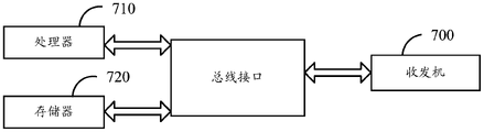
- FIG. 7 is a structural diagram of a device provided by an embodiment of the present disclosure.
- the device is a first device, as shown in FIG. 7, including a memory 720, a transceiver 700, and a processor 710:
- the memory 720 is used to store computer programs; the transceiver 700 is used to send and receive data under the control of the processor 710; the processor 710 is used to read the computer programs in the memory 720 and perform the following operations:
- the second direction is the direction in which the main lobe direction of the transmitting beam of the first device is aligned with the second device, and the first direction is different from the second direction;
- the main lobe direction of the transmit beam is switched from the second direction to the first direction or the third direction, where the third direction is different from the second direction.
- the bus architecture may include any number of interconnected buses and bridges, specifically one or more processors represented by processor 710 and various circuits of memory represented by memory 720 are linked together.
- the bus architecture may also link together various other circuits, such as peripherals, voltage regulators, and power management circuits, which are well known in the art and, therefore, will not be described further herein.
- the bus interface provides the interface.
- Transceiver 700 may be a number of elements, including a transmitter and a receiver, providing means for communicating with various other devices over transmission media including wireless channels, wired channels, fiber optic cables, and the like Transmission medium.
- the user interface 730 may also be an interface capable of externally connecting a required device, and the connected devices include but are not limited to a keypad, a display, a speaker, a microphone, a joystick, and the like.
- the processor 710 is responsible for managing the bus architecture and general processing, and the memory 720 may store data used by the processor 700 in performing operations.
- the processor 710 may be a CPU (central processor), an ASIC (Application Specific Integrated Circuit, an application specific integrated circuit), an FPGA (Field-Programmable Gate Array, a field programmable gate array) or a CPLD (Complex Programmable Logic Device) , complex programmable logic devices), the processor can also use a multi-core architecture.
- CPU central processor
- ASIC Application Specific Integrated Circuit
- FPGA Field-Programmable Gate Array
- CPLD Complex Programmable Logic Device
- complex programmable logic devices complex programmable logic devices
- the processor is configured to execute any one of the methods provided by the embodiments of the present disclosure according to the obtained executable instructions by invoking the computer program stored in the memory.
- the processor and memory may also be physically separated.
- the received signal strength of the second device is higher than the received signal strength of the second device in at least one first state, in the In the first state, the main lobe direction of the transmit beam of the second device is a direction other than the second direction, and the received signal strength of the second device is that the second device is directed against the first device. the received signal strength.
- the received signal strength of the second device is lower than that of the second device in at least one second state.
- the main lobe direction of the transmit beam of the second device is a direction other than the first direction or the third direction.
- the receiving signal of the second device The signal strength is the received signal strength of the second device for the first device.
- the second device includes:
- the reflection device has the capability of reflecting signals and the capability of receiving signals.
- processor 710 is further configured to:
- the first device sends configuration information to the second device, where the configuration information includes at least one of the following:
- the sending resource location of the sensing signal, the waveform information of the sensing signal, the configuration information of the second device, and the configuration information of the second device feeding back the sensing information.
- FIG. 8 is a structural diagram of a device provided by an embodiment of the present disclosure.
- the device is a second device, as shown in FIG. 8, including a memory 820, a transceiver 800, and a processor 810:
- the memory 820 is used to store computer programs; the transceiver 800 is used to send and receive data under the control of the processor 810; the processor 810 is used to read the computer program in the memory 820 and perform the following operations:
- the sensing signal is a sensing signal sent by the first device when the direction of the main lobe of the transmit beam is switched from a first direction to a second direction, where the second direction is the main lobe of the transmit beam of the first device
- the orientation is aligned with the orientation of the second device, the first orientation being different from the second orientation.
- the bus architecture may include any number of interconnected buses and bridges, specifically one or more processors represented by processor 810 and various circuits of memory represented by memory 820 are linked together.
- the bus architecture may also link together various other circuits, such as peripherals, voltage regulators, and power management circuits, which are well known in the art and, therefore, will not be described further herein.
- the bus interface provides the interface.
- Transceiver 800 may be a number of elements, including a transmitter and a receiver, providing means for communicating with various other devices over transmission media including wireless channels, wired channels, fiber optic cables, and the like Transmission medium.
- the user interface 830 may also be an interface capable of externally connecting the required equipment, and the connected equipment includes but is not limited to a keypad, a display, a speaker, a microphone, a joystick, and the like.
- the processor 810 is responsible for managing the bus architecture and general processing, and the memory 820 may store data used by the processor 800 in performing operations.
- the processor 810 may be a CPU (central processor), an ASIC (Application Specific Integrated Circuit, an application-specific integrated circuit), an FPGA (Field-Programmable Gate Array, a field programmable gate array) or a CPLD (Complex Programmable Logic Device) , complex programmable logic devices), the processor can also use a multi-core architecture.
- CPU central processor
- ASIC Application Specific Integrated Circuit
- FPGA Field-Programmable Gate Array
- CPLD Complex Programmable Logic Device
- complex programmable logic devices complex programmable logic devices
- the processor is configured to execute any one of the methods provided by the embodiments of the present disclosure according to the obtained executable instructions by invoking the computer program stored in the memory.
- the processor and memory may also be physically separated.
- processor 810 is further configured to:
- the target is detected according to the sensing signal received by the second device and the echo signal received by the second device.
- the detecting the target according to the sensing signal received by the second device and the echo signal received by the second device includes:
- the target is detected according to the sensing signal received by the second device, the echo signal received by the second device, and a reflection coefficient of the second device.
- the detecting the target according to the sensing signal received by the second device, the echo signal received by the second device, and the reflection coefficient of the second device including :
- the second receiving variable and the reflection coefficient of the second device calculate the transceiving response of the second device, and calculate the perception information of the target based on the transceiving response, and calculate the perception information of the target according to the perception of the target. information to detect the target;
- the first receiving variable is a receiving variable of the sensing signal received by the second device
- the second receiving variable is a receiving variable of the echo signal received by the second device.
- processor 810 is further configured to:
- the time-frequency resource location of the sensing signal, the waveform information of the sensing signal, the configuration information of the second device, and the configuration information of the second device feeding back the sensing information.
- FIG. 9 is a structural diagram of another device provided by an embodiment of the present disclosure.
- the device is a first device.
- a device 900 includes:
- the first sending unit 901 is configured to switch the main lobe direction of the transmit beam from a first direction to a second direction, and send a sensing signal, wherein the second direction is alignment of the main lobe direction of the transmit beam of the first device the direction of the second device, the first direction is different from the second direction;
- the switching unit 902 is configured to switch the main lobe direction of the transmit beam from the second direction to the first direction or the third direction after the sensing signal is sent, and the third direction is the same as the third direction.
- the two directions are different.
- the received signal strength of the second device is higher than the received signal strength of the second device in at least one first state, in the In the first state, the main lobe direction of the transmit beam of the second device is a direction other than the second direction, and the received signal strength of the second device is that the second device is directed against the first device. the received signal strength.
- the received signal strength of the second device is lower than that of the second device in at least one second state.
- the main lobe direction of the transmit beam of the second device is a direction other than the first direction or the third direction.
- the receiving signal of the second device The signal strength is the received signal strength of the second device for the first device.
- the optional second device includes:
- the reflection device has the capability of reflecting signals and the capability of receiving signals.
- the device further includes:
- a second sending unit configured to send configuration information to the second device, where the configuration information includes at least one of the following:
- the sending resource location of the sensing signal, the waveform information of the sensing signal, the configuration information of the second device, and the configuration information of the second device feeding back the sensing information.
- FIG. 10 is a structural diagram of another device provided by an embodiment of the present disclosure.
- the device is a second device.
- a device 1000 includes:
- a first receiving unit 1001 configured to receive a sensing signal sent by a first device
- the sensing signal is a sensing signal sent by the first device when the direction of the main lobe of the transmit beam is switched from a first direction to a second direction, where the second direction is the main lobe of the transmit beam of the first device
- the orientation is aligned with the orientation of the second device, the first orientation being different from the second orientation.
- the device further includes:
- a reflection unit 1002 configured to reflect the sensing signal
- the second receiving unit 1003 is configured to receive the echo signal generated by the target
- the detection unit 1004 is configured to detect the target according to the sensing signal received by the second device and the echo signal received by the second device.
- the detection unit 1004 is configured for the second device to perform the detection according to the sensing signal received by the second device, the echo signal received by the second device, and the reflection coefficient of the second device, The target is detected.
- the detection unit 1004 is configured to calculate the transceiving response of the second device according to the first receiving variable, the second receiving variable and the reflection coefficient of the second device, and calculate the target's transceiving response based on the transceiving response.
- Perceptual information detecting the target according to the perceptual information of the target;
- the first receiving variable is a receiving variable of the sensing signal received by the second device
- the second receiving variable is a receiving variable of the echo signal received by the second device.
- the device further includes:
- a third receiving unit configured to receive configuration information sent by the first device, where the configuration information includes at least one of the following:
- the time-frequency resource location of the sensing signal, the waveform information of the sensing signal, the configuration information of the second device, and the configuration information of the second device feeding back the sensing information.
- each functional unit in each embodiment of the present application may be integrated into one processing unit, or each unit may exist physically alone, or two or more units may be integrated into one unit.
- the above-mentioned integrated units may be implemented in the form of hardware, or may be implemented in the form of software functional units.
- the integrated unit is implemented in the form of a software functional unit and sold or used as an independent product, it may be stored in a processor-readable storage medium.
- the technical solution of the present application can be embodied in the form of a software product in essence, or the part that contributes to the related technology, or all or part of the technical solution, and the computer software product is stored in a storage medium.
- a computer device which may be a personal computer, a server, or a network device, etc.
- a processor processor
- the aforementioned storage medium includes: U disk, mobile hard disk, read-only memory (Read-Only Memory, ROM), random access memory (Random Access Memory, RAM), magnetic disk or optical disk and other media that can store program codes .
- An embodiment of the present disclosure further provides a processor-readable storage medium, where a computer program is stored in the processor-readable storage medium, and the computer program is used to cause the processor to execute the signal sending method provided by the embodiment of the present disclosure, Alternatively, the computer program is used to cause the processor to execute the target perception method provided by the embodiments of the present disclosure.
- the processor-readable storage medium can be any available medium or data storage device that can be accessed by a processor, including, but not limited to, magnetic storage (eg, floppy disk, hard disk, magnetic tape, magneto-optical disk (MO), etc.), optical storage (eg, CD, DVD, BD, HVD, etc.), and semiconductor memory (eg, ROM, EPROM, EEPROM, non-volatile memory (NAND FLASH), solid-state disk (SSD)), etc.
- magnetic storage eg, floppy disk, hard disk, magnetic tape, magneto-optical disk (MO), etc.
- optical storage eg, CD, DVD, BD, HVD, etc.
- semiconductor memory eg, ROM, EPROM, EEPROM, non-volatile memory (NAND FLASH), solid-state disk (SSD)
- the embodiments of the present application may be provided as a method, a system, or a computer program product. Accordingly, the present application may take the form of an entirely hardware embodiment, an entirely software embodiment, or an embodiment combining software and hardware aspects. Furthermore, the present application may take the form of a computer program product embodied on one or more computer-usable storage media having computer-usable program code embodied therein, including but not limited to disk storage, optical storage, and the like.
- processor-executable instructions may also be stored in a processor-readable memory capable of directing a computer or other programmable data processing apparatus to operate in a particular manner, such that the instructions stored in the processor-readable memory result in the manufacture of means including the instructions product, the instruction means implements the functions specified in the flow or flow of the flowchart and/or the block or blocks of the block diagram.
- processor-executable instructions can also be loaded onto a computer or other programmable data processing device to cause a series of operational steps to be performed on the computer or other programmable device to produce a computer-implemented process that Execution of the instructions provides steps for implementing the functions specified in the flowchart or blocks and/or the block or blocks of the block diagrams.
Landscapes
- Engineering & Computer Science (AREA)
- Radar, Positioning & Navigation (AREA)
- Remote Sensing (AREA)
- Computer Networks & Wireless Communication (AREA)
- Physics & Mathematics (AREA)
- General Physics & Mathematics (AREA)
- Signal Processing (AREA)
- Radar Systems Or Details Thereof (AREA)
- Mobile Radio Communication Systems (AREA)
Abstract
Description
相关申请的交叉引用CROSS-REFERENCE TO RELATED APPLICATIONS
本申请主张在2020年12月25日在中国提交的中国专利申请号No.202011558992.1的优先权,其全部内容通过引用包含于此。This application claims priority to Chinese Patent Application No. 202011558992.1 filed in China on Dec. 25, 2020, the entire contents of which are incorporated herein by reference.
本公开涉及通信技术领域和雷达领域,尤其涉及一种信号发送方法、目标感知方法、设备和存储介质。The present disclosure relates to the field of communication technologies and radar, and in particular, to a signal transmission method, a target perception method, a device and a storage medium.
随着通信和雷达技术发展目前通过设备发送的信号对目标进行感知的应用也越来越多,例如:毫米波合成孔径雷达(SAR,Synthetic Aperture Radar,SAR)成像技术。然而,目前发送感知信号主要是通过提高感知信号发送设备的收发天线的隔离度来实现的,而增加收发天线的隔离度往往会导致设备尺寸变大。With the development of communication and radar technology, there are more and more applications of target perception through signals sent by devices, such as millimeter-wave synthetic aperture radar (SAR, Synthetic Aperture Radar, SAR) imaging technology. However, currently, the sensing signal is transmitted mainly by improving the isolation degree of the transceiver antenna of the sensing signal transmission device, and increasing the isolation degree of the transceiver antenna often leads to an increase in the size of the device.
发明内容SUMMARY OF THE INVENTION
本公开实施例提供一种信号发送方法、目标感知方法、设备和存储介质,以解决设备尺寸变大的问题。Embodiments of the present disclosure provide a signal sending method, a target sensing method, a device, and a storage medium, so as to solve the problem that the size of the device increases.
本公开实施例提供一种信号发送方法,包括:An embodiment of the present disclosure provides a signal sending method, including:
第一设备将发射波束主瓣方向由第一方向切换为第二方向,并发送感知信号;其中,所述第二方向为所述第一设备的发射波束主瓣方向对准第二设备的方向,所述第一方向与所述第二方向不同;The first device switches the main lobe direction of the transmission beam from the first direction to the second direction, and sends a sensing signal; wherein the second direction is the direction in which the main lobe direction of the transmission beam of the first device is aligned with the second device , the first direction is different from the second direction;
在发送完所述感知信号后,所述第一设备将所述发射波束主瓣方向由所述第二方向切换为所述第一方向或者第三方向,所述第三方向与所述第二方向不同。After sending the sensing signal, the first device switches the main lobe direction of the transmit beam from the second direction to the first direction or the third direction, the third direction is the same as the second direction The directions are different.
可选的,在所述发射波束主瓣方向为所述第二方向的情况下,所述第二设备的接收信号强度高于至少一个第一状态下所述第二设备的接收信号强度, 在所述第一状态下所述第二设备的发射波束主瓣方向为除所述第二方向之外的方向,所述第二设备的接收信号强度为所述第二设备针对所述第一设备的接收信号强度。Optionally, in the case where the main lobe direction of the transmit beam is the second direction, the received signal strength of the second device is higher than the received signal strength of the second device in at least one first state, in In the first state, the main lobe direction of the transmit beam of the second device is a direction other than the second direction, and the received signal strength of the second device is that the second device is directed against the first device. the received signal strength.
可选的,在所述发射波束主瓣方向为所述第一方向或者为所述第三方向的情况下,所述第二设备的接收信号强度低于至少一个第二状态下所述第二设备的接收信号强度,在所述第二状态下所述第二设备的的发射波束主瓣方向为除所述第一方向或者所述第三方向之外的方向,所述第二设备的接收信号强度为所述第二设备针对所述第一设备的接收信号强度。Optionally, when the main lobe direction of the transmit beam is the first direction or the third direction, the received signal strength of the second device is lower than that of the second device in at least one second state. The received signal strength of the device. In the second state, the main lobe direction of the transmit beam of the second device is a direction other than the first direction or the third direction. The receiving signal of the second device The signal strength is the received signal strength of the second device for the first device.
可选的,所述第二设备包括:Optionally, the second device includes:
目标或者反射设备;target or reflective equipment;
其中,所述反射设备具备反射信号的能力和接收信号的能力。Wherein, the reflection device has the capability of reflecting signals and the capability of receiving signals.
可选的,所述方法还包括:Optionally, the method further includes:
所述第一设备向所述第二设备发送配置信息,其中,所述配置信息包括如下至少一项:The first device sends configuration information to the second device, where the configuration information includes at least one of the following:
所述感知信号的发送资源位置、所述感知信号的波形信息、所述第二设备的配置信息、所述第二设备反馈感知信息的配置信息。The sending resource location of the sensing signal, the waveform information of the sensing signal, the configuration information of the second device, and the configuration information of the second device feeding back the sensing information.
本公开实施例还提供一种目标感知方法,包括:Embodiments of the present disclosure also provide a target perception method, including:
第二设备接收第一设备发送的感知信号;The second device receives the sensing signal sent by the first device;
其中,所述感知信号为所述第一设备将发射波束主瓣方向由第一方向切换为第二方向发送的感知信号,其中,所述第二方向为所述第一设备的发射波束主瓣方向对准第二设备的方向,所述第一方向与所述第二方向不同。The sensing signal is a sensing signal sent by the first device when the direction of the main lobe of the transmit beam is switched from a first direction to a second direction, where the second direction is the main lobe of the transmit beam of the first device The orientation is aligned with the orientation of the second device, the first orientation being different from the second orientation.
可选的,所述方法还包括:Optionally, the method further includes:
所述第二设备反射所述感知信号;the second device reflects the sensing signal;
所述第二设备接收目标产生的回波信号;The second device receives the echo signal generated by the target;
所述第二设备依据所述第二设备接收到的所述感知信号和所述第二设备接收到的所述回波信号,对所述目标进行检测。The second device detects the target according to the sensing signal received by the second device and the echo signal received by the second device.
可选的,所述第二设备依据所述第二设备接收到的所述感知信号和所述第二设备接收的所述回波信号,对所述目标进行检测,包括:Optionally, the second device detects the target according to the sensing signal received by the second device and the echo signal received by the second device, including:
所述第二设备依据所述第二设备接收到的所述感知信号、所述第二设备 接收的所述回波信号和所述第二设备的反射系数,对所述目标进行检测。The second device detects the target according to the sensing signal received by the second device, the echo signal received by the second device, and the reflection coefficient of the second device.
可选的,所述第二设备依据所述第二设备接收到的所述感知信号、所述第二设备接收的所述回波信号和所述第二设备的反射系数,对所述目标进行检测,包括:Optionally, the second device performs the detection on the target according to the sensing signal received by the second device, the echo signal received by the second device, and the reflection coefficient of the second device. testing, including:
所述第二设备依据第一接收变量、第二接收变量和所述第二设备的反射系数,计算所述第二设备的收发响应,并基于所述收发响应计算所述目标的感知信息,根据所述目标的感知信息,对所述目标进行检测;The second device calculates the sending and receiving response of the second device according to the first receiving variable, the second receiving variable and the reflection coefficient of the second device, and calculates the perception information of the target based on the sending and receiving response, according to The perception information of the target, to detect the target;
其中,所述第一接收变量为所述第二设备接收到所述感知信号的接收变量,所述第二接收变量为所述第二设备接收到所述回波信号的接收变量。The first receiving variable is a receiving variable of the sensing signal received by the second device, and the second receiving variable is a receiving variable of the echo signal received by the second device.
可选的,所述方法还包括:Optionally, the method further includes:
所述第二设备接收所述第一设备发送的配置信息,其中,所述配置信息包括如下至少一项:The second device receives the configuration information sent by the first device, where the configuration information includes at least one of the following:
所述感知信号的时频资源位置、所述感知信号的波形信息、所述第二设备的配置信息、所述第二设备反馈感知信息的配置信息。The time-frequency resource location of the sensing signal, the waveform information of the sensing signal, the configuration information of the second device, and the configuration information of the second device feeding back the sensing information.
本公开实施例还提供一种设备,所述设备为第一设备,包括:存储器、收发机和处理器,其中:An embodiment of the present disclosure further provides a device, where the device is a first device, including: a memory, a transceiver, and a processor, wherein:
存储器,用于存储计算机程序;收发机,用于在所述处理器的控制下收发数据;处理器,用于读取所述存储器中的计算机程序并执行以下操作:a memory for storing a computer program; a transceiver for sending and receiving data under the control of the processor; a processor for reading the computer program in the memory and performing the following operations:
将发射波束主瓣方向由第一方向切换为第二方向,并发送感知信号,其中,所述第二方向为所述第一设备的发射波束主瓣方向对准第二设备的方向,所述第一方向与所述第二方向不同;Switch the main lobe direction of the transmission beam from the first direction to the second direction, and send a sensing signal, wherein the second direction is the direction in which the main lobe direction of the transmission beam of the first device is aligned with the second device, and the the first direction is different from the second direction;
在发送完所述感知信号后,所述第一设备将所述发射波束主瓣方向由所述第二方向切换为所述第一方向或者第三方向,所述第三方向与所述第二方向不同。After sending the sensing signal, the first device switches the main lobe direction of the transmit beam from the second direction to the first direction or the third direction, the third direction is the same as the second direction The directions are different.
可选的,在所述发射波束主瓣方向为所述第二方向的情况下,所述第二设备的接收信号强度高于至少一个第一状态下所述第二设备的接收信号强度,在所述第一状态下所述第二设备的发射波束主瓣方向为除所述第二方向之外的方向,所述第二设备的接收信号强度为所述第二设备针对所述第一设备的接收信号强度。Optionally, in the case where the main lobe direction of the transmit beam is the second direction, the received signal strength of the second device is higher than the received signal strength of the second device in at least one first state, in the In the first state, the main lobe direction of the transmit beam of the second device is a direction other than the second direction, and the received signal strength of the second device is that the second device is directed against the first device. the received signal strength.
可选的,在所述发射波束主瓣方向为所述第一方向或者为所述第三方向的情况下,所述第二设备的接收信号强度低于至少一个第二状态下所述第二设备的接收信号强度,在所述第二状态下所述第二设备的的发射波束主瓣方向为除所述第一方向或者所述第三方向之外的方向,所述第二设备的接收信号强度为所述第二设备针对所述第一设备的接收信号强度。Optionally, when the main lobe direction of the transmit beam is the first direction or the third direction, the received signal strength of the second device is lower than that of the second device in at least one second state. The received signal strength of the device. In the second state, the main lobe direction of the transmit beam of the second device is a direction other than the first direction or the third direction. The receiving signal of the second device The signal strength is the received signal strength of the second device for the first device.
本公开实施例还提供一种设备,所述设备为第二设备,包括:存储器、收发机和处理器,其中:An embodiment of the present disclosure further provides a device, the device is a second device, including: a memory, a transceiver, and a processor, wherein:
存储器,用于存储计算机程序;收发机,用于在所述处理器的控制下收发数据;处理器,用于读取所述存储器中的计算机程序并执行以下操作:a memory for storing a computer program; a transceiver for sending and receiving data under the control of the processor; a processor for reading the computer program in the memory and performing the following operations:
接收第一设备发送的感知信号;receiving a sensing signal sent by the first device;
其中,所述感知信号为所述第一设备将发射波束主瓣方向由第一方向切换为第二方向发送的感知信号,其中,所述第二方向为所述第一设备的发射波束主瓣方向对准第二设备的方向,所述第一方向与所述第二方向不同。The sensing signal is a sensing signal sent by the first device when the direction of the main lobe of the transmit beam is switched from a first direction to a second direction, where the second direction is the main lobe of the transmit beam of the first device The orientation is aligned with the orientation of the second device, the first orientation being different from the second orientation.
可选的,所述处理器还包括:Optionally, the processor further includes:
反射所述感知信号;reflect the perception signal;
接收目标产生的回波信号;Receive the echo signal generated by the target;
依据所述第二设备接收到的所述感知信号和所述第二设备接收到的所述回波信号,对所述目标进行检测。The target is detected according to the sensing signal received by the second device and the echo signal received by the second device.
可选的,所述依据所述第二设备接收到的所述感知信号和所述第二设备接收的所述回波信号,对所述目标进行检测,包括:Optionally, the detecting the target according to the sensing signal received by the second device and the echo signal received by the second device includes:
依据所述第二设备接收到的所述感知信号、所述第二设备接收的所述回波信号和所述第二设备的反射系数,对所述目标进行检测。The target is detected according to the sensing signal received by the second device, the echo signal received by the second device, and a reflection coefficient of the second device.
本公开实施例还提供一种设备,所述设备为第一设备,包括:An embodiment of the present disclosure further provides a device, where the device is a first device, including:
第一发送单元,用于将发射波束主瓣方向由第一方向切换为第二方向,并发送感知信号,其中,所述第二方向为所述第一设备的发射波束主瓣方向对准第二设备的方向,所述第一方向与所述第二方向不同;The first sending unit is configured to switch the main lobe direction of the transmission beam from the first direction to the second direction, and send a sensing signal, wherein the second direction is that the main lobe direction of the transmission beam of the first device is aligned with the first direction. Two directions of the device, the first direction is different from the second direction;
切换单元,用于在发送完所述感知信号后,将所述发射波束主瓣方向由所述第二方向切换为所述第一方向或者第三方向,所述第三方向与所述第二方向不同。a switching unit, configured to switch the main lobe direction of the transmit beam from the second direction to the first direction or the third direction after sending the sensing signal, the third direction is the same as the second direction The directions are different.
可选的,在所述发射波束主瓣方向为所述第二方向的情况下,所述第二设备的接收信号强度高于至少一个第一状态下所述第二设备的接收信号强度,在所述第一状态下所述第二设备的发射波束主瓣方向为除所述第二方向之外的方向,所述第二设备的接收信号强度为所述第二设备针对所述第一设备的接收信号强度。Optionally, in the case where the main lobe direction of the transmit beam is the second direction, the received signal strength of the second device is higher than the received signal strength of the second device in at least one first state, in the In the first state, the main lobe direction of the transmit beam of the second device is a direction other than the second direction, and the received signal strength of the second device is that the second device is directed against the first device. the received signal strength.
可选的,在所述发射波束主瓣方向为所述第一方向或者为所述第三方向的情况下,所述第二设备的接收信号强度低于至少一个第二状态下所述第二设备的接收信号强度,在所述第二状态下所述第二设备的的发射波束主瓣方向为除所述第一方向或者所述第三方向之外的方向,所述第二设备的接收信号强度为所述第二设备针对所述第一设备的接收信号强度。Optionally, when the main lobe direction of the transmit beam is the first direction or the third direction, the received signal strength of the second device is lower than that of the second device in at least one second state. The received signal strength of the device. In the second state, the main lobe direction of the transmit beam of the second device is a direction other than the first direction or the third direction. The receiving signal of the second device The signal strength is the received signal strength of the second device for the first device.
本公开实施例还提供一种设备,所述设备为第二设备,包括:An embodiment of the present disclosure further provides a device, where the device is a second device, including:
第一接收单元,用于接收第一设备发送的感知信号;a first receiving unit, configured to receive a sensing signal sent by the first device;
其中,所述感知信号为所述第一设备将发射波束主瓣方向由第一方向切换为第二方向发送的感知信号,其中,所述第二方向为所述第一设备的发射波束主瓣方向对准第二设备的方向,所述第一方向与所述第二方向不同。The sensing signal is a sensing signal sent by the first device when the direction of the main lobe of the transmit beam is switched from a first direction to a second direction, where the second direction is the main lobe of the transmit beam of the first device The orientation is aligned with the orientation of the second device, the first orientation being different from the second orientation.
可选的,所述设备还包括:Optionally, the device further includes:
反射单元,用于反射所述感知信号;a reflection unit for reflecting the sensing signal;
第二接收单元,用于接收目标产生的回波信号;a second receiving unit, configured to receive the echo signal generated by the target;
检测单元,用于依据所述第二设备接收到的所述感知信号和所述第二设备接收到的所述回波信号,对所述目标进行检测。A detection unit, configured to detect the target according to the sensing signal received by the second device and the echo signal received by the second device.
可选的,所述检测单元用于依据所述第二设备接收到的所述感知信号、所述第二设备接收的所述回波信号和所述第二设备的反射系数,对所述目标进行检测。Optionally, the detection unit is configured to detect the target according to the sensing signal received by the second device, the echo signal received by the second device, and the reflection coefficient of the second device. test.
本公开实施例还提供一种处理器可读存储介质,所述处理器可读存储介质存储有计算机程序,所述计算机程序用于使所述处理器执行本公开实施例的信号发送方法,或者,所述计算机程序用于使所述处理器执行本公开实施例的目标感知方法。An embodiment of the present disclosure further provides a processor-readable storage medium, where the processor-readable storage medium stores a computer program, and the computer program is used to cause the processor to execute the signal sending method of the embodiment of the present disclosure, or , the computer program is used to cause the processor to execute the target perception method of the embodiment of the present disclosure.
本公开实施例中,第一设备将发射波束主瓣方向由第一方向切换为第二方向,并发送感知信号;其中,所述第二方向为所述第一设备的发射波束主 瓣方向对准第二设备的方向,所述第一方向与所述第二方向不同;在发送完所述感知信号后,所述第一设备将所述发射波束主瓣方向由所述第二方向切换为所述第一方向或者第三方向,所述第三方向与所述第二方向不同。由于通过切换主瓣方向实现感知信号的发送,从而不需要增加收发天线的隔离度,以避免增大设备尺寸。In this embodiment of the present disclosure, the first device switches the direction of the main lobe of the transmit beam from the first direction to the second direction, and sends a sensing signal; wherein the second direction is the direction of the main lobe of the transmit beam of the first device. the direction of the second device, the first direction is different from the second direction; after sending the sensing signal, the first device switches the main lobe direction of the transmit beam from the second direction to The first direction or the third direction, the third direction is different from the second direction. Since the sensing signal is sent by switching the direction of the main lobe, it is not necessary to increase the isolation of the transceiver antenna to avoid increasing the size of the device.
图1是本公开实施可应用的一种网络构架的结构示意图;1 is a schematic structural diagram of a network architecture to which the present disclosure is applicable;
图2是本公开实施可应用的一种场景示意图;FIG. 2 is a schematic diagram of a scenario to which the present disclosure is applicable;
图3是本公开实施例提供的一种信号发送方法的流程图;3 is a flowchart of a signal sending method provided by an embodiment of the present disclosure;
图4是本公开实施可应用的一种信号发送的示意图;FIG. 4 is a schematic diagram of a signal transmission applicable to the implementation of the present disclosure;
图5是本公开实施例提供的一种目标感知方法的流程图;5 is a flowchart of a target sensing method provided by an embodiment of the present disclosure;
图6是本公开实施可应用的一种波束发送方向的切换时间示意图;FIG. 6 is a schematic diagram of switching time of a beam transmission direction to which the present disclosure is applicable;
图7是本公开实施例提供的一种设备的结构图;7 is a structural diagram of a device provided by an embodiment of the present disclosure;
图8是本公开实施例提供的另一种设备的结构图;8 is a structural diagram of another device provided by an embodiment of the present disclosure;
图9是本公开实施例提供的另一种设备的结构图;9 is a structural diagram of another device provided by an embodiment of the present disclosure;
图10是本公开实施例提供的另一种设备的结构图;10 is a structural diagram of another device provided by an embodiment of the present disclosure;
图11是本公开实施例提供的另一种设备的结构图。FIG. 11 is a structural diagram of another device provided by an embodiment of the present disclosure.
为使本公开要解决的技术问题、技术方案和优点更加清楚,下面将结合附图及具体实施例进行详细描述。In order to make the technical problems, technical solutions and advantages to be solved by the present disclosure more clear, detailed description will be given below with reference to the accompanying drawings and specific embodiments.
本公开实施例中术语“和/或”,描述关联对象的关联关系,表示可以存在三种关系,例如,A和/或B,可以表示:单独存在A,同时存在A和B,单独存在B这三种情况。字符“/”一般表示前后关联对象是一种“或”的关系。In the embodiments of the present disclosure, the term "and/or" describes the association relationship of associated objects, and indicates that there can be three kinds of relationships. For example, A and/or B can indicate that A exists alone, A and B exist at the same time, and B exists alone these three situations. The character "/" generally indicates that the associated objects are an "or" relationship.
本公开实施例中术语“多个”是指两个或两个以上,其它量词与之类似。In the embodiments of the present disclosure, the term "plurality" refers to two or more than two, and other quantifiers are similar.
下面将结合本公开实施例中的附图,对本公开实施例中的技术方案进行清楚、完整地描述,显然,所描述的实施例仅仅是本申请一部分实施例,并不是全部的实施例。基于本申请中的实施例,本领域普通技术人员在没有做 出创造性劳动前提下所获得的所有其他实施例,都属于本申请保护的范围。The technical solutions in the embodiments of the present disclosure will be clearly and completely described below with reference to the accompanying drawings in the embodiments of the present disclosure. Obviously, the described embodiments are only a part of the embodiments of the present application, not all of the embodiments. Based on the embodiments in this application, all other embodiments obtained by those of ordinary skill in the art without creative work, all belong to the scope of protection of this application.
本公开实施例提供一种信号发送方法、目标感知方法、设备和存储介质,以解决设备尺寸变大的问题。Embodiments of the present disclosure provide a signal sending method, a target sensing method, a device, and a storage medium, so as to solve the problem that the size of the device increases.
其中,方法和设备是基于同一申请构思的,由于方法和设备解决问题的原理相似,因此装置和方法的实施可以相互参见,重复之处不再赘述。The method and the device are conceived based on the same application. Since the principles of the method and the device for solving the problem are similar, the implementation of the device and the method can be referred to each other, and the repetition will not be repeated.
本公开实施例提供的技术方案可以适用于多种系统,尤其是6G系统。例如适用的系统可以是全球移动通讯(global system of mobile communication,GSM)系统、码分多址(code division multiple access,CDMA)系统、宽带码分多址(Wideband Code Division Multiple Access,WCDMA)通用分组无线业务(general packet radio service,GPRS)系统、长期演进(long term evolution,LTE)系统、LTE频分双工(frequency division duplex,FDD)系统、LTE时分双工(time division duplex,TDD)系统、高级长期演进(long term evolution advanced,LTE-A)系统、通用移动系统(universal mobile telecommunication system,UMTS)、全球互联微波接入(worldwide interoperability for microwave access,WiMAX)系统、5G新空口(New Radio,NR)系统、6G系统等。这多种系统中均包括终端设备和网络设备。系统中还可以包括核心网部分,例如演进的分组系统(Evloved Packet System,EPS)、5G系统(5GS)等。The technical solutions provided by the embodiments of the present disclosure may be applicable to various systems, especially 6G systems. For example, applicable systems may be global system of mobile communication (GSM) system, code division multiple access (CDMA) system, wideband code division multiple access (Wideband Code Division Multiple Access, WCDMA) general packet Wireless service (general packet radio service, GPRS) system, long term evolution (long term evolution, LTE) system, LTE frequency division duplex (frequency division duplex, FDD) system, LTE time division duplex (time division duplex, TDD) system, Long term evolution advanced (LTE-A) system, universal mobile telecommunication system (UMTS), worldwide interoperability for microwave access (WiMAX) system, 5G New Radio (New Radio, NR) system, 6G system, etc. These various systems include terminal equipment and network equipment. The system may also include a core network part, such as an evolved packet system (Evloved Packet System, EPS), a 5G system (5GS), and the like.
请参见图1,图1是本公开实施可应用的网络构架的结构示意图,如图1所示,包括第一设备11和第二设备12,其中,第一设备11可以是网络设备,第二设备12可以是目标或者反射设备。进一步的,上述网络构架还包括终端13,或者,在上述第二设备12为反射设备的情况下,上述网络框架如图2所示,还包括目标,目标可以称作目标物体或者目标对象。Please refer to FIG. 1. FIG. 1 is a schematic structural diagram of a network architecture applicable to the implementation of the present disclosure. As shown in FIG. 1, it includes a
其中,本公开实施例涉及的终端,可以是指向用户提供语音和/或数据连通性的设备,具有无线连接功能的手持式设备、或连接到无线调制解调器的其他处理设备等。在不同的系统中,终端设备的名称可能也不相同,例如在5G系统中,终端设备可以称为用户设备(User Equipment,UE)。无线终端设备可以经无线接入网(Radio Access Network,RAN)与一个或多个核心网(Core Network,CN)进行通信,无线终端设备可以是移动终端设备,如移动电话(或称为“蜂窝”电话)和具有移动终端设备的计算机,例如,可以是便 携式、袖珍式、手持式、计算机内置的或者车载的移动装置,它们与无线接入网交换语言和/或数据。例如,个人通信业务(Personal Communication Service,PCS)电话、无绳电话、会话发起协议(Session Initiated Protocol,SIP)话机、无线本地环路(Wireless Local Loop,WLL)站、个人数字助理(Personal Digital Assistant,PDA)、Redcap终端等设备。无线终端设备也可以称为系统、订户单元(subscriber unit)、订户站(subscriber station),移动站(mobile station)、移动台(mobile)、远程站(remote station)、接入点(access point)、远程终端设备(remote terminal)、接入终端设备(access terminal)、用户终端设备(user terminal)、用户代理(user agent)、用户装置(user device),本公开实施例中并不限定。The terminal involved in the embodiments of the present disclosure may be a device that provides voice and/or data connectivity to a user, a handheld device with a wireless connection function, or other processing device connected to a wireless modem. In different systems, the name of the terminal device may be different. For example, in the 5G system, the terminal device may be called user equipment (User Equipment, UE). Wireless terminal equipment can communicate with one or more core networks (Core Network, CN) via a radio access network (Radio Access Network, RAN). "telephone) and computers with mobile terminal equipment, eg portable, pocket-sized, hand-held, computer-built or vehicle-mounted mobile devices, which exchange language and/or data with the radio access network. For example, Personal Communication Service (PCS) phones, cordless phones, Session Initiated Protocol (SIP) phones, Wireless Local Loop (WLL) stations, Personal Digital Assistants (Personal Digital Assistants), PDA), Redcap terminal and other equipment. Wireless terminal equipment may also be referred to as system, subscriber unit, subscriber station, mobile station, mobile station, remote station, access point , a remote terminal device (remote terminal), an access terminal device (access terminal), a user terminal device (user terminal), a user agent (user agent), and a user device (user device), which are not limited in the embodiments of the present disclosure.
本公开实施例涉及的网络设备,可以是基站,该基站可以包括多个为终端提供服务的小区。根据具体应用场合不同,基站又可以称为接入点,或者可以是接入网中在空中接口上通过一个或多个扇区与无线终端设备通信的设备,或者其它名称。网络设备可用于将收到的空中帧与网际协议(Internet Protocol,IP)分组进行相互更换,作为无线终端设备与接入网的其余部分之间的路由器,其中接入网的其余部分可包括网际协议(IP)通信网络。网络设备还可协调对空中接口的属性管理。例如,本公开实施例涉及的网络设备可以是全球移动通信系统(Global System for Mobile communications,GSM)或码分多址接入(Code Division Multiple Access,CDMA)中的网络设备(Base Transceiver Station,BTS),也可以是带宽码分多址接入(Wide-band Code Division Multiple Access,WCDMA)中的网络设备(NodeB),还可以是长期演进(long term evolution,LTE)系统中的演进型网络设备(evolutional Node B,eNB或e-NodeB)、5G网络架构(next generation system)中的5G基站(gNB)、6G中的基站,也可以是家庭演进基站(Home evolved Node B,HeNB)、中继节点(relay node)、家庭基站(femto)、微微基站(pico)等,本公开实施例中并不限定。在一些网络结构中,网络设备可以包括集中单元(centralized unit,CU)节点和分布单元(distributed unit,DU)节点,集中单元和分布单元也可以地理上分开布置。The network device involved in the embodiments of the present disclosure may be a base station, and the base station may include a plurality of cells providing services for the terminal. Depending on the specific application, the base station may also be called an access point, or may be a device in the access network that communicates with wireless terminal equipment through one or more sectors on the air interface, or other names. The network device can be used to exchange received air frames with Internet Protocol (IP) packets, and act as a router between the wireless terminal device and the rest of the access network, which can include the Internet. Protocol (IP) communication network. The network devices may also coordinate attribute management for the air interface. For example, the network device involved in the embodiments of the present disclosure may be a network device (Base Transceiver Station, BTS) in the Global System for Mobile Communications (GSM) or Code Division Multiple Access (Code Division Multiple Access, CDMA). ), it can also be a network device (NodeB) in Wide-band Code Division Multiple Access (WCDMA), or it can be an evolved network device in a long term evolution (LTE) system (evolutional Node B, eNB or e-NodeB), 5G base station (gNB) in 5G network architecture (next generation system), base station in 6G, or Home evolved Node B (HeNB), relay A node (relay node), a home base station (femto), a pico base station (pico), etc., are not limited in the embodiments of the present disclosure. In some network structures, a network device may include a centralized unit (CU) node and a distributed unit (DU) node, and the centralized unit and the distributed unit may also be geographically separated.
网络设备与终端之间可以各自使用一或多根天线进行多输入多输出 (Multi Input Multi Output,MIMO)传输,MIMO传输可以是单用户MIMO(Single User MIMO,SU-MIMO)或多用户MIMO(Multiple User MIMO,MU-MIMO)。根据根天线组合的形态和数量,MIMO传输可以是2D-MIMO、3D-MIMO、FD-MIMO或massive-MIMO,也可以是分集传输或预编码传输或波束赋形传输等。One or more antennas can be used between the network device and the terminal for multiple input multiple output (Multi Input Multi Output, MIMO) transmission, and the MIMO transmission can be single user MIMO (Single User MIMO, SU-MIMO) or multi-user MIMO ( Multiple User MIMO, MU-MIMO). According to the form and number of root antenna combinations, MIMO transmission can be 2D-MIMO, 3D-MIMO, FD-MIMO, or massive-MIMO, or diversity transmission, precoding transmission, or beamforming transmission.
本公开实施例中,目标可以是需要被感知的物体,例如:人物、车辆等物体,且如图2所示,在一些场景中目标与第一设备11之间可以被遮挡物遮挡或者不存在遮挡物。In this embodiment of the present disclosure, the target may be an object that needs to be perceived, such as a person, a vehicle, etc., and as shown in FIG. 2 , in some scenarios, the distance between the target and the
本公开实施例中,反射设备可以是具备反射信号的能力和接收信号的能力的电子设备,例如:大规模天线阵列或者智能超表面等电子设备。In the embodiment of the present disclosure, the reflecting device may be an electronic device having the capability of reflecting signals and the capability of receiving signals, for example, electronic devices such as a large-scale antenna array or a smart metasurface.
请参见图3,图3是本公开实施例提供的一种信号发送方法的流程图,如图3所示,包括以下步骤:Please refer to FIG. 3. FIG. 3 is a flowchart of a signal sending method provided by an embodiment of the present disclosure. As shown in FIG. 3, the method includes the following steps:
步骤301、第一设备将发射波束主瓣方向由第一方向切换为第二方向,并发送感知信号;其中,所述第二方向为所述第一设备的发射波束主瓣方向对准第二设备的方向,所述第一方向与所述第二方向不同;Step 301: The first device switches the direction of the main lobe of the transmission beam from the first direction to the second direction, and sends a sensing signal; wherein, the second direction is that the main lobe direction of the transmission beam of the first device is aligned with the second direction. the orientation of the device, the first orientation is different from the second orientation;
步骤302、在发送完所述感知信号后,所述第一设备将所述发射波束主瓣方向由所述第二方向切换为所述第一方向或者第三方向,所述第三方向与所述第二方向不同。Step 302: After sending the sensing signal, the first device switches the main lobe direction of the transmit beam from the second direction to the first direction or the third direction, and the third direction is the same as the other direction. The second direction is different.
上述第一设备将发射波束主瓣方向由第一方向切换为第二方向可以是,在需要发送感知信号时,将发射波束主瓣方向由第一方向切换为第二方向,即将发射波束主瓣方向对准上述第二设备发送感知信号。而第一方向与第二方向不同,这样可以实现在切换为上述第二方向前上述发射波束主瓣方向不是对准上述第二设备的,例如:如图2所示,对准终端发送通信信号,即避开上述第二设备发送通信信号。The above-mentioned first device switches the direction of the main lobe of the transmitting beam from the first direction to the second direction may be, when the sensing signal needs to be sent, the direction of the main lobe of the transmitting beam is switched from the first direction to the second direction. The direction is aimed at the above-mentioned second device to send a sensing signal. The first direction is different from the second direction, so that the main lobe direction of the transmit beam is not aligned with the second device before switching to the second direction. For example, as shown in Figure 2, the communication signal is sent to the terminal. , that is, avoiding the second device to send the communication signal.
在发送完上述感知信号后,第一设备将所述发射波束主瓣方向由所述第二方向切换为所述第一方向或者第三方向,同样由于第三方向与第二方向不同,这样可以实现在发送完上述感知信号后,上述发射波束主瓣方向不对准上述第二设备的,即避开上述第二设备。通过上述步骤可以实现在发送感知信号前和后,上述发射波束主瓣方向不是对准上述第二设备的,这样可以第 一设备在此期间可以发送其他信号,不需要增加收发天线的隔离度,以避免增大设备尺寸,例如:如图2所示,第一设备在此期间向终端发送通信信号。另外,还可以实现在不发送感知信号的期间避免上述发射波束发送的信号影响第二设备,以提高第二设备感知目标的准确性。After sending the above sensing signal, the first device switches the main lobe direction of the transmit beam from the second direction to the first direction or the third direction. Also, because the third direction is different from the second direction, this can After the sensing signal is sent, if the direction of the main lobe of the transmitting beam is not aligned with the second device, the second device is avoided. Through the above steps, it can be achieved that before and after the sensing signal is sent, the main lobe direction of the transmission beam is not aligned with the second device, so that the first device can send other signals during this period, and it is not necessary to increase the isolation of the transceiver antenna. In order to avoid increasing the size of the device, for example, as shown in FIG. 2 , the first device sends a communication signal to the terminal during this period. In addition, it can also be implemented to prevent the signal sent by the transmission beam from affecting the second device during the period when the sensing signal is not sent, so as to improve the accuracy of the second device sensing the target.
以上述第二设备为智能超表面为例,如图4所示,上述第二方向可以如图4所示的波束方向402,上述第一方向或者第三方向可以如图4所示的波束方向401。Taking the above-mentioned second device as an intelligent metasurface as an example, as shown in FIG. 4 , the above-mentioned second direction may be the
本公开实施例中,上述第一设备可以所述发射波束为数字波束,本公开实施例并不限定为数字波束,也可以是其他能够进行波束方向切换的波束。另外,可以通过波束赋形(beamforming)来实现发射波束主瓣方向的切换。In the embodiment of the present disclosure, the above-mentioned first device may use the transmit beam as a digital beam. The embodiment of the present disclosure is not limited to a digital beam, and may also be other beams capable of beam direction switching. In addition, the switching of the direction of the main lobe of the transmit beam can be realized by beamforming.
作为一种可选的实施方式,在所述发射波束主瓣方向为所述第二方向的情况下,所述第二设备的接收信号强度高于至少一个第一状态下所述第二设备的接收信号强度,在所述第一状态下所述第二设备的发射波束主瓣方向为除所述第二方向之外的方向,所述第二设备的接收信号强度为所述第二设备针对所述第一设备的接收信号强度。As an optional implementation manner, when the main lobe direction of the transmit beam is the second direction, the received signal strength of the second device is higher than that of the second device in at least one first state The received signal strength, in the first state, the main lobe direction of the transmit beam of the second device is a direction other than the second direction, and the received signal strength of the second device is the The received signal strength of the first device.
上述至少一个第一状态可以是除发射波束主瓣方向为第二方向之外的任一状态,这样可以实现当发射波束主瓣方向为第二方向时,第二设备接收到的第一设备的信号强度最大,即比发射波束主瓣方向为任何其他方向时第二设备接收到的第一设备的信号强度都要大,以提高第二设备对目标的感知效果。或者上述第一个状态可以是除发射波束主瓣方向为第二方向之外的部分状态,这样可以实现当发射波束主瓣方向为第二方向时,第二设备接收到的第一设备的信号强度次强或者较强的。The above-mentioned at least one first state can be any state except that the main lobe direction of the transmission beam is the second direction, so that when the main lobe direction of the transmission beam is the second direction, the second device receives the first device's The signal strength is the highest, that is, the signal strength of the first device received by the second device when the main lobe direction of the transmit beam is in any other direction is greater, so as to improve the perception effect of the second device on the target. Or the above-mentioned first state may be a partial state except that the main lobe direction of the transmitting beam is the second direction, so that when the main lobe direction of the transmitting beam is the second direction, the signal of the first device received by the second device can be realized. The intensity is second or stronger.
该实施方式中,由于在所述发射波束主瓣方向为所述第二方向时的所述第二设备的接收信号强度高于至少一个第一状态时所述第二设备的接收信号强度,这样可以提高第二设备对目标的感知效果。In this embodiment, since the received signal strength of the second device when the main lobe direction of the transmit beam is the second direction is higher than the received signal strength of the second device when the at least one first state is in the first state, so The perception effect of the second device on the target can be improved.
作为一种可选的实施方式,在所述发射波束主瓣方向为所述第一方向或者为所述第三方向的情况下,所述第二设备的接收信号强度低于至少一个第二状态下所述第二设备的接收信号强度,在所述第二状态下所述第二设备的的发射波束主瓣方向为除所述第一方向或者所述第三方向之外的方向,所述 第二设备的接收信号强度为所述第二设备针对所述第一设备的接收信号强度。As an optional implementation manner, when the direction of the main lobe of the transmit beam is the first direction or the third direction, the received signal strength of the second device is lower than at least one second state the received signal strength of the second device, in the second state, the main lobe direction of the transmit beam of the second device is a direction other than the first direction or the third direction, the The received signal strength of the second device is the received signal strength of the second device for the first device.
在上述至少一个第一状态可以是除发射波束主瓣方向为第一方向或者第三方向之外的任一状态,这样可以实现当发射波束主瓣方向为第一方向或第三方向时,第二设备接收到的第一设备的信号强度最小,即比发射波束主瓣方向为任何其他方向时第二设备接收到的第一设备的信号强度都要小。上述第一个状态可以是除发射波束主瓣方向为第一方向或者第三方向之外的部分状态,可以实现当发射波束主瓣方向为第一方向或第三方向时,第二设备接收到的第一设备的信号强度次小或者较弱的。The at least one first state can be any state except that the main lobe direction of the transmitting beam is the first direction or the third direction, so that when the main lobe direction of the transmitting beam is the first direction or the third direction, the first The signal strength of the first device received by the second device is the smallest, that is, the signal strength of the first device received by the second device is smaller than the signal strength of the first device received by the second device when the main lobe direction of the transmit beam is in any other direction. The above-mentioned first state may be a partial state except that the main lobe direction of the transmitting beam is the first direction or the third direction, so that when the main lobe direction of the transmitting beam is the first direction or the third direction, the second device receives the The signal strength of the first device is the second smallest or weaker.
该实施方式中,由于在所述发射波束主瓣方向为所述第一方向或者所述第三方向时的所述第二设备的接收信号强度低于至少一个第二状态时所述第二设备的接收信号强度,这样可以避免影响第二设备对目标的感知。In this implementation manner, when the main lobe direction of the transmit beam is the first direction or the third direction, the received signal strength of the second device is lower than that of the second device when the strength of the received signal is lower than at least one second state. the received signal strength, so as to avoid affecting the perception of the target by the second device.
一些实施方式,当发射波束主瓣方向为第二方向时,第一设备发射的波束,其主瓣方向是对准第二设备的。当发射波束主瓣方向为第一方向或第三方向时,第一设备发射的波束,其主瓣方向是不对准第二设备的,并且旁瓣方向也是不对准第二设备的,通过选择第一设备发射波束的方向,使得第二设备接收到的第一设备的信号强度最小化,以避免影响第二设备对目标的感知。In some embodiments, when the direction of the main lobe of the transmitted beam is the second direction, the direction of the main lobe of the beam transmitted by the first device is aimed at the second device. When the main lobe direction of the transmitted beam is the first direction or the third direction, the main lobe direction of the beam transmitted by the first device is not aligned with the second device, and the side lobe direction is also not aligned with the second device. The direction of the beam transmitted by one device minimizes the signal strength of the first device received by the second device to avoid affecting the perception of the target by the second device.
作为一种可选的实施方式,所述第二设备包括:As an optional implementation manner, the second device includes:
目标或者反射设备;target or reflective equipment;
其中,所述反射设备具备反射信号的能力和接收信号的能力。Wherein, the reflection device has the capability of reflecting signals and the capability of receiving signals.
上述目标可以是需要被感知的物体或者对象,例如:人物、车辆等物体。The above-mentioned target may be an object or object that needs to be perceived, such as a person, a vehicle and other objects.
上述反射设备可以是具备反射信号的能力和接收信号的能力的电子设备,例如:大规模天线阵列或者智能超表面等电子设备。The above-mentioned reflecting device may be an electronic device capable of reflecting signals and receiving signals, such as electronic devices such as large-scale antenna arrays or smart metasurfaces.
作为一种可选的实施方式,所述方法还包括:As an optional embodiment, the method further includes:
所述第一设备向所述第二设备发送配置信息,其中,所述配置信息包括如下至少一项:The first device sends configuration information to the second device, where the configuration information includes at least one of the following:
所述感知信号的发送资源位置、所述感知信号的波形信息、所述第二设备的配置信息、所述第二设备反馈感知信息的配置信息。The sending resource location of the sensing signal, the waveform information of the sensing signal, the configuration information of the second device, and the configuration information of the second device feeding back the sensing information.
其中,上述发送资源位置可以包括时频资源位置,上述感知信号的波形 信息可以包括感知信号的离开角(AoD),上述第二设备的配置信息可以包括第二设备对目标检测的行为配置信息,上述第二设备反馈感知信息的配置信息所述第二设备反馈感知信息的配置信息。Wherein, the above-mentioned sending resource locations may include time-frequency resource locations, the waveform information of the sensing signal may include the angle of departure (AoD) of the sensing signal, and the configuration information of the second device may include the behavior configuration information of the second device for target detection, The second device feeds back the configuration information of the perception information. The second device feeds back the configuration information of the perception information.
在一些实施方式中,感知信号可以是特殊设计使得第二设备能够比较容易检测出感知信号,例如:伪随机序列。需要说明的是,本公开实施例中,对感知信号不作限定。In some embodiments, the sensing signal may be specially designed so that the second device can relatively easily detect the sensing signal, such as a pseudo-random sequence. It should be noted that, in the embodiment of the present disclosure, the sensing signal is not limited.
在一些实施方式中,第一设备发送的感知信号功率可以是预功率或者协议中定义的功率。进一步的,第一设备发送感知信号的功率可以使得感知信号经过第二设备反射、目标反射到达第二设备时最终的接收信噪比大于给预设阈值SNR0,这样可以提高第二设备的感知效果。In some embodiments, the power of the sensing signal sent by the first device may be pre-power or power defined in the protocol. Further, the power of the sensing signal sent by the first device can make the final received signal-to-noise ratio greater than the preset threshold SNR0 when the sensing signal is reflected by the second device and the target reflects to the second device, which can improve the sensing effect of the second device. .
在一些实施方式中,在上述发射波束主瓣方向为上述第二方向,或者为上述第一方向或者第三方向时,例如:第一设备的波束主瓣方向和最小功率方向分别对准第二设备时,第二设备两次检测到感知信号的接收信噪比均大于预设阈值SNR1,这样可以进一步提高第二设备的感知效果。In some embodiments, when the main lobe direction of the transmit beam is the second direction, or the first direction or the third direction, for example, the beam main lobe direction and the minimum power direction of the first device are respectively aligned with the second direction. When the second device detects that the received signal-to-noise ratio of the sensing signal is greater than the preset threshold SNR1 twice, the sensing effect of the second device can be further improved.
在一些实施方式中,本公开实施例提供的上述方法可以应用于宏小区或微小区,且第一设备与目标之间可以不存在遮挡物。In some implementation manners, the above-mentioned method provided by the embodiments of the present disclosure may be applied to a macro cell or a micro cell, and there may be no obstruction between the first device and the target.
本公开实施例中,第一设备将发射波束主瓣方向由第一方向切换为第二方向,并发送感知信号;其中,所述第二方向为所述第一设备的发射波束主瓣方向对准第二设备的方向,所述第一方向与所述第二方向不同;在发送完所述感知信号后,所述第一设备将所述发射波束主瓣方向由所述第二方向切换为所述第一方向或者第三方向,所述第三方向与所述第二方向不同。由于通过切换主瓣方向实现感知信号的发送,从而不需要增加收发天线的隔离度,以避免增大设备尺寸。In this embodiment of the present disclosure, the first device switches the direction of the main lobe of the transmit beam from the first direction to the second direction, and sends a sensing signal; wherein the second direction is the direction of the main lobe of the transmit beam of the first device. the direction of the second device, the first direction is different from the second direction; after sending the sensing signal, the first device switches the main lobe direction of the transmit beam from the second direction to The first direction or the third direction, the third direction is different from the second direction. Since the sensing signal is sent by switching the direction of the main lobe, it is not necessary to increase the isolation of the transceiver antenna to avoid increasing the size of the device.
请参见图5,图5是本公开实施例提供的一种目标感知方法的流程图,如图5所示,包括以下步骤:Please refer to FIG. 5. FIG. 5 is a flowchart of a target sensing method provided by an embodiment of the present disclosure. As shown in FIG. 5, the following steps are included:
步骤501、第二设备接收第一设备发送的感知信号;
其中,所述感知信号为所述第一设备将发射波束主瓣方向由第一方向切换为第二方向发送的感知信号;其中,所述第二方向为所述第一设备的发射波束主瓣方向对准第二设备的方向,所述第一方向与所述第二方向不同。The sensing signal is a sensing signal sent by the first device when the main lobe direction of the transmit beam is switched from the first direction to the second direction; wherein the second direction is the main lobe of the transmit beam of the first device The orientation is aligned with the orientation of the second device, the first orientation being different from the second orientation.
作为一种可选的实施方式,所述方法还包括:As an optional embodiment, the method further includes:
所述第二设备反射所述感知信号;the second device reflects the sensing signal;
所述第二设备接收目标产生的回波信号;The second device receives the echo signal generated by the target;
所述第二设备依据所述第二设备接收到的所述感知信号和所述第二设备接收到的所述回波信号,对所述目标进行检测。The second device detects the target according to the sensing signal received by the second device and the echo signal received by the second device.
如图4所示,第二设备接收到上述第一设备发送的感知信号后,对该感知信号进行反射,而目标接收到反射的感知信号会产生对应的回波信号,从而步骤503接收到上述回波信号。As shown in FIG. 4 , after receiving the sensing signal sent by the first device, the second device reflects the sensing signal, and the target receives the reflected sensing signal to generate a corresponding echo signal, so step 503 receives the above-mentioned sensing signal. echo signal.
所述第二设备依据所述第二设备接收到的所述感知信号和所述第二设备接收到的所述回波信号,对所述目标进行检测可以是:依据上述接收到的感知信号和回波信号检测目标的位置、大小、图像等内容。另外,上述对所述目标进行检测也可以称作对目标进行感知。The detection of the target by the second device according to the sensing signal received by the second device and the echo signal received by the second device may be: according to the sensing signal received and the echo signal received by the second device. The echo signal detects the position, size, image and other contents of the target. In addition, the above-mentioned detection of the target may also be referred to as target perception.
本实施例中,通过上述步骤可以实现对目标特征进行感知,由于第二设备不需要具备主动发送信号的能力就可以实现对目标的感知,从而降低第二设备的复杂度。In this embodiment, the above steps can realize the perception of the target feature, because the second device does not need to have the ability to actively send signals to realize the target perception, thereby reducing the complexity of the second device.
作为一种可选的实施方式,所述第二设备依据所述第二设备接收到的所述感知信号和所述第二设备接收的所述回波信号,对所述目标进行检测,包括:As an optional implementation manner, the second device detects the target according to the sensing signal received by the second device and the echo signal received by the second device, including:
所述第二设备依据所述第二设备接收到的所述感知信号、所述第二设备接收的所述回波信号和所述第二设备的反射系数,对所述目标进行检测。The second device detects the target according to the sensing signal received by the second device, the echo signal received by the second device, and a reflection coefficient of the second device.
其中,上述第二设备的反射系统可以是第一设备配置的,或者第二设备预配置的。The reflection system of the second device may be configured by the first device or preconfigured by the second device.
在一种实施方式,所述第二设备依据所述第二设备接收到的所述感知信号、所述第二设备接收的所述回波信号和所述第二设备的反射系数,对所述目标进行检测,包括:In an implementation manner, the second device performs the evaluation on the second device according to the sensing signal received by the second device, the echo signal received by the second device, and a reflection coefficient of the second device. target detection, including:
所述第二设备依据第一接收变量、第二接收变量和所述第二设备的反射系数,计算所述第二设备的收发响应,并基于所述收发响应计算所述目标的感知信息,根据所述目标的感知信息,对所述目标进行检测;The second device calculates the sending and receiving response of the second device according to the first receiving variable, the second receiving variable and the reflection coefficient of the second device, and calculates the perception information of the target based on the sending and receiving response, according to The perception information of the target, to detect the target;
其中,所述第一接收变量为所述第二设备接收到所述感知信号的接收变 量,所述第二接收变量为所述第二设备接收到所述回波信号的接收变量。Wherein, the first received variable is the received variable of the sensing signal received by the second device, and the second received variable is the received variable of the echo signal received by the second device.
上述第一接收变量可以为第二设备接收到所述感知信号的电场或者功率等,上述第二接收变量可以为第二设备接收到所述回波信号的电场或者功率等。上述电场可以是使用第二设备的射频基带(RF-BB)链路检测的电场。另外,通过从第一设备上接收的感知信号的电场乘上天线单元的反射系数,可以得到第二设备在该天线单元的感知信号发射电场。The first receiving variable may be the electric field or power of the sensing signal received by the second device, and the second receiving variable may be the electric field or power of the echo signal received by the second device. The aforementioned electric field may be an electric field detected using a radio frequency baseband (RF-BB) link of the second device. In addition, by multiplying the electric field of the sensing signal received from the first device by the reflection coefficient of the antenna unit, the transmitting electric field of the sensing signal of the second device at the antenna unit can be obtained.
上述感知信息可以是目标特征的图像信息或者形状信息或者尺寸信息等,如目标的3D图像。The above-mentioned perception information may be image information or shape information or size information of the target feature, such as a 3D image of the target.
上述收发响应可以通过如下公式计算:The above-mentioned sending and receiving responses can be calculated by the following formula:
R(x,y,f)=Er(x,y)/Ei(x,y)/Г(x,y)R(x,y,f)=Er(x,y)/Ei(x,y)/Г(x,y)
其中,R(x,y,f)=表示上述接收响应,上述Ei(x,y)表示第二设备接收到所述感知信号的电场,Er(x,y)表示第二设备接收到所述回波信号的电场,(x,y)表示接收到上述感知信号和回波信号的感知单元(天线单元或智能超表面单元),Г(x,y)为坐标为(x,y)的感知单元(天线单元或智能超表面单元)的反射系数,其中f为感知信号的载频。Wherein, R(x,y,f)=represents the above-mentioned receiving response, the above-mentioned Ei(x,y) represents the electric field of the sensing signal received by the second device, and Er(x,y) represents that the second device receives the said sensing signal The electric field of the echo signal, (x, y) represents the sensing unit (antenna unit or intelligent metasurface unit) that receives the above sensing signal and echo signal, Г(x, y) is the sensing unit whose coordinates are (x, y) The reflection coefficient of the unit (antenna unit or smart metasurface unit), where f is the carrier frequency of the sensed signal.
一种方式中,第二设备可以采用空域傅立叶(Fourier)变换方法基于上述收发响应计算所述目标的感知信息。In one manner, the second device may use a spatial Fourier transform method to calculate the perception information of the target based on the above-mentioned transceiving responses.
例如:通过如下公式计算上述目标的感知信息:For example, the perceptual information of the above target is calculated by the following formula:


其中,R(x,y,f)表示上述第二设备的收发响应,在第二设备的一个平面的坐标(x,y)点上感知信号的频率为f;上述S(k x,k y,f)表示收发响应的空间傅里叶变换,k为波数,k x为X方向的波数,k y为Y方向的波数,k z为Z方向的波数;Z 1是第二设备的Z轴坐标,第二设备是垂直于Z轴的固定位置的一个平面;f(x,y,z)表示目标的感知信息,例如:3D图像信息。 Among them, R(x, y, f) represents the sending and receiving response of the second device, and the frequency of the sensed signal at the coordinate (x, y) point of a plane of the second device is f; the above S(k x , k y ,f) represents the spatial Fourier transform of the sending and receiving response, k is the wave number, k x is the wave number in the X direction, ky is the wave number in the Y direction, k z is the wave number in the Z direction; Z 1 is the Z axis of the second device Coordinates, the second device is a plane with a fixed position perpendicular to the Z axis; f(x, y, z) represents the perception information of the target, for example: 3D image information.
需要说明的是,本公开实施例中并不限定通过上述方式计算感知信息,例如:还可以根据第二设备接收到回波信号的功率和接收到回波信号的时延, 确定上述感知信息。It should be noted that the embodiments of the present disclosure are not limited to calculating the sensing information in the above manner. For example, the sensing information may also be determined according to the power of the echo signal received by the second device and the delay of receiving the echo signal.
一种方式,第二设备可以基于毫米波时延光谱TDS技术计算所述目标的感知信息,例如:毫米波时延光谱TDS技术,TDS技术使用飞秒激光技术获得宽频毫米波脉冲,由分束器分为抽运波和探测波,抽运波用于激发毫米波源,探测波用于驱动毫米波探测器,毫米波源产生的毫米波脉冲照射到目标,毫米波探测器接收由目标反射的脉冲信号,探测在探测波脉冲到达时刻的毫米波电场强度,通过改变探测波到达毫米波探测器的时间,得到毫米波电场强度随时间的变化,再通过时域傅里叶变换,就得到反射频谱,包含了幅度和相位信息,从而得到目标的感知信息。In one way, the second device can calculate the perception information of the target based on millimeter-wave time-delay spectroscopy TDS technology, for example: millimeter-wave time-delay spectroscopy TDS technology, TDS technology uses femtosecond laser technology to obtain broadband millimeter-wave pulses, which are split by beams. The detector is divided into pump wave and probe wave. The pump wave is used to excite the millimeter wave source, and the probe wave is used to drive the millimeter wave detector. The millimeter wave pulse generated by the millimeter wave source is irradiated to the target, and the millimeter wave detector receives the pulse reflected by the target. Signal, detect the millimeter-wave electric field intensity at the time when the detection wave pulse arrives, change the time when the detection wave arrives at the millimeter-wave detector, obtain the change of the millimeter-wave electric field intensity with time, and then pass the time domain Fourier transform to get the reflection spectrum , including the amplitude and phase information, so as to obtain the perception information of the target.
需要说明的是,本公开实施例中并不限定基于所述收发响应计算所述目标的感知信息的计算方式,例如:除了上述计算方式之外,还可以采用协议中已定义或者后续新定义的计算方式。It should be noted that the embodiment of the present disclosure does not limit the calculation method for calculating the perception information of the target based on the transceiving response. For example, in addition to the above calculation method, the method already defined in the protocol or newly defined subsequently may also be used. Calculation.
作为一种可选的实施方式,所述方法还包括:As an optional embodiment, the method further includes:
所述第二设备接收所述第一设备发送的配置信息,其中,所述配置信息包括如下至少一项:The second device receives the configuration information sent by the first device, where the configuration information includes at least one of the following:
所述感知信号的时频资源位置、所述感知信号的波形信息、所述第二设备的配置信息、所述第二设备反馈感知信息的配置信息。The time-frequency resource location of the sensing signal, the waveform information of the sensing signal, the configuration information of the second device, and the configuration information of the second device feeding back the sensing information.
需要说明的是,本实施例作为与图3所示的实施例中对应的网络设备的实施方式,其具体的实施方式可以参见图3所示的实施例的相关说明,为了避免重复说明,本实施例不再赘述,且还可以达到相同有益效果。It should be noted that this embodiment is an implementation of the network device corresponding to the embodiment shown in FIG. 3 , and reference may be made to the relevant description of the embodiment shown in FIG. 3 for the specific implementation. The embodiments will not be repeated, and the same beneficial effects can also be achieved.
下面通过一个实施例对本公开实施例提供的方法进行举例说明:The method provided by the embodiment of the present disclosure is exemplified below through an embodiment:
实施例:Example:
该实施例中可以包括如下步骤:This embodiment may include the following steps:
步骤1、第一设备向第二设备发送感知信号的配置信息,包括时频资源位置、离开角(AoD)、波形等信息中的至少一个。Step 1. The first device sends configuration information of the sensing signal to the second device, including at least one of information such as time-frequency resource location, angle of departure (AoD), and waveform.
步骤2、第一设备发送感知信号前,使用波束赋形(beamforming)技术,把发送信号的最小功率方向对准第二设备,如方向图中最小的方向对准第二设备。Step 2: Before the first device sends the sensing signal, the beamforming technology is used to align the minimum power direction of the transmitted signal to the second device, such as the smallest direction in the directional diagram, to the second device.
例如:第一设备可以随着时间切换波束方向,第一设备的基带数字波束 赋形的时间粒度是纳秒级或者更低,比如,在1.5GHz带宽是系统中,可以使用0.67ns粒度切换数字波束赋形的方向。如图4所示,第一设备开始时刻正在使用401所示波束方向服务终端,与终端进行通信信号的传输,比如,持续时间为0~1us(=1000ns)。For example, the first device can switch the beam direction over time, and the time granularity of the baseband digital beamforming of the first device is nanoseconds or lower. The direction of the beamforming. As shown in FIG. 4 , the first device is using the beam direction indicated by 401 to serve the terminal at the beginning, and transmits a communication signal with the terminal, for example, the duration is 0-1us (=1000ns).
步骤3、第一设备使用beamforming技术,信号主瓣方向对准第二设备,在配置的时频资源位置上,向第二设备发送感知信号。Step 3: The first device uses the beamforming technology, the main lobe direction of the signal is aligned with the second device, and sends a sensing signal to the second device at the configured time-frequency resource position.
例如:如图4所示,第一设备切换到402所示的波束方向,波束方向对准第二设备的中心,使得第二设备服务感知成像,进行感知信号的传输,比如,持续时间为1us~1000.67ns共0.67ns。For example: as shown in Figure 4, the first device switches to the beam direction shown in 402, and the beam direction is aligned with the center of the second device, so that the second device serves perception imaging and transmits the perception signal, for example, the duration is 1us ~1000.67ns for a total of 0.67ns.
步骤4、第二设备接收第一设备发送的感知信号,测量得到第二设备上坐标为(x,y)的天线单元(或智能超表面单元)信号的电场Ei(x,y)。Step 4: The second device receives the sensing signal sent by the first device, and measures the electric field Ei(x, y) of the signal of the antenna unit (or smart metasurface unit) whose coordinates are (x, y) on the second device.
步骤5、第一设备发送完毕感知信号后,使用beamforming技术,把发送信号的最小功率方向对准第二设备,如方向图中最小的方向对准第二设备。Step 5. After the first device sends the sensing signal, it uses beamforming technology to align the minimum power direction of the transmitted signal to the second device, such as the smallest direction in the direction diagram, to the second device.
例如:如图4所示,第一设备再次切换到401所示的波束方向服务终端,与终端进行通信信号的传输,比如,持续时间为1000.67ns~2000.67ns。For example, as shown in FIG. 4 , the first device switches to the beam direction service terminal shown in 401 again, and transmits a communication signal with the terminal, for example, the duration is 1000.67ns to 2000.67ns.
具体的,第一设备切换波束方式的时间可以如图6所示,例如:在1000ns中使用波束方向A发送通信信号,在0.67ns中使用波束方向B发送感知信号,在另一个在1000ns中使用波束方向C发送通信信号。Specifically, the time for the first device to switch the beam mode may be as shown in Figure 6. For example, in 1000ns, use beam direction A to send communication signals, in 0.67ns use beam direction B to send sensing signals, and in another use beam direction B in 1000ns. Beam direction C transmits communication signals.
步骤6、第二设备接收目标反射的感知信号(即回波信号),测量得到第二设备上坐标为(x,y)的天线单元信号的电场Er(x,y)。Step 6: The second device receives the sensing signal (ie, the echo signal) reflected by the target, and measures the electric field Er(x, y) of the antenna unit signal whose coordinates are (x, y) on the second device.
本实施例中,第二设备除了可以控制反射信号,还可以接收信号,即接收两个不同时间上的感知信号。一是第二设备在1us时刻后会测量到目标感知信号,这是第一设备发送到第二设备的感知信号。第一设备发送的感知信号再经过第二设备的反射可以到达目标,目标会产生回波信号,所以,二是第二设备在测量到第一设备发送的感知信号后的几到几十纳秒时间范围内会测量到感知信号的回波信号。In this embodiment, in addition to controlling the reflected signal, the second device can also receive signals, that is, receive two sensing signals at different times. One is that the second device will measure the target sensing signal after 1us, which is the sensing signal sent by the first device to the second device. The sensing signal sent by the first device can reach the target after being reflected by the second device, and the target will generate an echo signal. Therefore, the second is a few to tens of nanoseconds after the second device measures the sensing signal sent by the first device. The echo signal of the sensed signal is measured within the time frame.
步骤7、第二设备计算收发响应R(x,y,f),即接收电场与反射出去的电场的比值,其中f为感知信号的载频。例如:假设第二设备上坐标为(x,y)的天线单元(或智能超表面单元)的反射系数为Г(x,y),可以得到R(x,y,f)=Er(x,y)/ Ei(x,y)/Г(x,y),其中。第一设备可以先配置好第二设备的天线单元的反射系数。Step 7: The second device calculates the transceiving response R(x, y, f), that is, the ratio of the received electric field to the reflected electric field, where f is the carrier frequency of the sensing signal. For example: Assuming that the reflection coefficient of the antenna unit (or smart metasurface unit) whose coordinates are (x, y) on the second device is Г(x, y), we can get R(x, y, f)=Er(x, y)/Ei(x,y)/Г(x,y), where. The first device may first configure the reflection coefficient of the antenna unit of the second device.
步骤8、第二设备通过R(x,y,f)得到目标的3D图像f(x,y,z),方法可以采用上述空域Fourier变换方法。Step 8. The second device obtains the 3D image f(x, y, z) of the target through R(x, y, f), and the method may adopt the above-mentioned spatial domain Fourier transform method.
一些实施方式中,第二设备还可以利用这两个接收到的感知信号、配置信息和地图信息等,获得目标的3D图像。In some embodiments, the second device may also obtain a 3D image of the target by using the two received sensing signals, configuration information, map information, and the like.
步骤9、第二设备把获得的目标的3D图像发送给第一设备或网络,这里的网络可以是网络服务器或者其他网络设备。Step 9: The second device sends the obtained 3D image of the target to the first device or the network, where the network may be a network server or other network devices.
请参见图7,图7是本公开实施例提供的一种设备的结构图,该设备为第一设备,如图7所示,包括存储器720、收发机700和处理器710:Please refer to FIG. 7. FIG. 7 is a structural diagram of a device provided by an embodiment of the present disclosure. The device is a first device, as shown in FIG. 7, including a
存储器720,用于存储计算机程序;收发机700,用于在所述处理器710的控制下收发数据;处理器710,用于读取所述存储器720中的计算机程序并执行以下操作:The
将发射波束主瓣方向由第一方向切换为第二方向,并发送感知信号;其中,所述第二方向为所述第一设备的发射波束主瓣方向对准第二设备的方向,所述第一方向与所述第二方向不同;Switch the main lobe direction of the transmitting beam from the first direction to the second direction, and send a sensing signal; wherein, the second direction is the direction in which the main lobe direction of the transmitting beam of the first device is aligned with the second device, and the the first direction is different from the second direction;
在发送完所述感知信号后,将所述发射波束主瓣方向由所述第二方向切换为所述第一方向或者第三方向,所述第三方向与所述第二方向不同。After the sensing signal is sent, the main lobe direction of the transmit beam is switched from the second direction to the first direction or the third direction, where the third direction is different from the second direction.
其中,在图7中,总线架构可以包括任意数量的互联的总线和桥,具体由处理器710代表的一个或多个处理器和存储器720代表的存储器的各种电路链接在一起。总线架构还可以将诸如外围设备、稳压器和功率管理电路等之类的各种其他电路链接在一起,这些都是本领域所公知的,因此,本文不再对其进行进一步描述。总线接口提供接口。收发机700可以是多个元件,即包括发送机和接收机,提供用于在传输介质上与各种其他装置通信的单元,这些传输介质包括,这些传输介质包括无线信道、有线信道、光缆等传输介质。针对不同的用户设备,用户接口730还可以是能够外接内接需要设备的接口,连接的设备包括但不限于小键盘、显示器、扬声器、麦克风、操纵杆等。7, the bus architecture may include any number of interconnected buses and bridges, specifically one or more processors represented by
处理器710负责管理总线架构和通常的处理,存储器720可以存储处理器700在执行操作时所使用的数据。The
可选的,处理器710可以是CPU(中央处埋器)、ASIC(Application Specific Integrated Circuit,专用集成电路)、FPGA(Field-Programmable Gate Array,现场可编程门阵列)或CPLD(Complex Programmable Logic Device,复杂可编程逻辑器件),处理器也可以采用多核架构。Optionally, the
处理器通过调用存储器存储的计算机程序,用于按照获得的可执行指令执行本公开实施例提供的任一所述方法。处理器与存储器也可以物理上分开布置。The processor is configured to execute any one of the methods provided by the embodiments of the present disclosure according to the obtained executable instructions by invoking the computer program stored in the memory. The processor and memory may also be physically separated.
可选的,在所述发射波束主瓣方向为所述第二方向的情况下,所述第二设备的接收信号强度高于至少一个第一状态下所述第二设备的接收信号强度,在所述第一状态下所述第二设备的发射波束主瓣方向为除所述第二方向之外的方向,所述第二设备的接收信号强度为所述第二设备针对所述第一设备的接收信号强度。Optionally, in the case where the main lobe direction of the transmit beam is the second direction, the received signal strength of the second device is higher than the received signal strength of the second device in at least one first state, in the In the first state, the main lobe direction of the transmit beam of the second device is a direction other than the second direction, and the received signal strength of the second device is that the second device is directed against the first device. the received signal strength.
可选的,在所述发射波束主瓣方向为所述第一方向或者为所述第三方向的情况下,所述第二设备的接收信号强度低于至少一个第二状态下所述第二设备的接收信号强度,在所述第二状态下所述第二设备的的发射波束主瓣方向为除所述第一方向或者所述第三方向之外的方向,所述第二设备的接收信号强度为所述第二设备针对所述第一设备的接收信号强度。Optionally, when the main lobe direction of the transmit beam is the first direction or the third direction, the received signal strength of the second device is lower than that of the second device in at least one second state. The received signal strength of the device. In the second state, the main lobe direction of the transmit beam of the second device is a direction other than the first direction or the third direction. The receiving signal of the second device The signal strength is the received signal strength of the second device for the first device.
可选的,所述第二设备包括:Optionally, the second device includes:
目标或者反射设备;target or reflective equipment;
其中,所述反射设备具备反射信号的能力和接收信号的能力。Wherein, the reflection device has the capability of reflecting signals and the capability of receiving signals.
可选的,处理器710还用于:Optionally, the
所述第一设备向所述第二设备发送配置信息,其中,所述配置信息包括如下至少一项:The first device sends configuration information to the second device, where the configuration information includes at least one of the following:
所述感知信号的发送资源位置、所述感知信号的波形信息、所述第二设备的配置信息、所述第二设备反馈感知信息的配置信息。The sending resource location of the sensing signal, the waveform information of the sensing signal, the configuration information of the second device, and the configuration information of the second device feeding back the sensing information.
在此需要说明的是,本公开实施例提供的上述设备,能够实现上述方法实施例所实现的所有方法步骤,且能够达到相同的技术效果,在此不再对本实施例中与方法实施例相同的部分及有益效果进行具体赘述。It should be noted here that the above-mentioned device provided by the embodiment of the present disclosure can realize all the method steps realized by the above-mentioned method embodiment, and can achieve the same technical effect, and the same as the method embodiment in this embodiment is not repeated here. The parts and beneficial effects will be described in detail.
请参见图8,图8是本公开实施例提供的一种设备的结构图,该设备为 第二设备,如图8所示,包括存储器820、收发机800和处理器810:Please refer to FIG. 8. FIG. 8 is a structural diagram of a device provided by an embodiment of the present disclosure. The device is a second device, as shown in FIG. 8, including a
存储器820,用于存储计算机程序;收发机800,用于在所述处理器810的控制下收发数据;处理器810,用于读取所述存储器820中的计算机程序并执行以下操作:The
接收第一设备发送的感知信号;receiving a sensing signal sent by the first device;
其中,所述感知信号为所述第一设备将发射波束主瓣方向由第一方向切换为第二方向发送的感知信号,其中,所述第二方向为所述第一设备的发射波束主瓣方向对准第二设备的方向,所述第一方向与所述第二方向不同。The sensing signal is a sensing signal sent by the first device when the direction of the main lobe of the transmit beam is switched from a first direction to a second direction, where the second direction is the main lobe of the transmit beam of the first device The orientation is aligned with the orientation of the second device, the first orientation being different from the second orientation.
其中,在图8中,总线架构可以包括任意数量的互联的总线和桥,具体由处理器810代表的一个或多个处理器和存储器820代表的存储器的各种电路链接在一起。总线架构还可以将诸如外围设备、稳压器和功率管理电路等之类的各种其他电路链接在一起,这些都是本领域所公知的,因此,本文不再对其进行进一步描述。总线接口提供接口。收发机800可以是多个元件,即包括发送机和接收机,提供用于在传输介质上与各种其他装置通信的单元,这些传输介质包括,这些传输介质包括无线信道、有线信道、光缆等传输介质。针对不同的用户设备,用户接口830还可以是能够外接内接需要设备的接口,连接的设备包括但不限于小键盘、显示器、扬声器、麦克风、操纵杆等。8, the bus architecture may include any number of interconnected buses and bridges, specifically one or more processors represented by
处理器810负责管理总线架构和通常的处理,存储器820可以存储处理器800在执行操作时所使用的数据。The
可选的,处理器810可以是CPU(中央处埋器)、ASIC(Application Specific Integrated Circuit,专用集成电路)、FPGA(Field-Programmable Gate Array,现场可编程门阵列)或CPLD(Complex Programmable Logic Device,复杂可编程逻辑器件),处理器也可以采用多核架构。Optionally, the
处理器通过调用存储器存储的计算机程序,用于按照获得的可执行指令执行本公开实施例提供的任一所述方法。处理器与存储器也可以物理上分开布置。The processor is configured to execute any one of the methods provided by the embodiments of the present disclosure according to the obtained executable instructions by invoking the computer program stored in the memory. The processor and memory may also be physically separated.
可选的,处理器810还用于:Optionally, the
反射所述感知信号;reflect the perception signal;
接收目标产生的回波信号;Receive the echo signal generated by the target;
依据所述第二设备接收到的所述感知信号和所述第二设备接收到的所述回波信号,对所述目标进行检测。The target is detected according to the sensing signal received by the second device and the echo signal received by the second device.
可选的,所述依据所述第二设备接收到的所述感知信号和所述第二设备接收的所述回波信号,对所述目标进行检测,包括:Optionally, the detecting the target according to the sensing signal received by the second device and the echo signal received by the second device includes:
依据所述第二设备接收到的所述感知信号、所述第二设备接收的所述回波信号和所述第二设备的反射系数,对所述目标进行检测。The target is detected according to the sensing signal received by the second device, the echo signal received by the second device, and a reflection coefficient of the second device.
可选的,所述依据所述第二设备接收到的所述感知信号、所述第二设备接收的所述回波信号和所述第二设备的反射系数,对所述目标进行检测,包括:Optionally, the detecting the target according to the sensing signal received by the second device, the echo signal received by the second device, and the reflection coefficient of the second device, including :
依据第一接收变量、第二接收变量和所述第二设备的反射系数,计算所述第二设备的收发响应,并基于所述收发响应计算所述目标的感知信息,根据所述目标的感知信息,对所述目标进行检测;According to the first receiving variable, the second receiving variable and the reflection coefficient of the second device, calculate the transceiving response of the second device, and calculate the perception information of the target based on the transceiving response, and calculate the perception information of the target according to the perception of the target. information to detect the target;
其中,所述第一接收变量为所述第二设备接收到所述感知信号的接收变量,所述第二接收变量为所述第二设备接收到所述回波信号的接收变量。The first receiving variable is a receiving variable of the sensing signal received by the second device, and the second receiving variable is a receiving variable of the echo signal received by the second device.
可选的,处理器810还用于:Optionally, the
接收所述第一设备发送的配置信息,其中,所述配置信息包括如下至少一项:Receive configuration information sent by the first device, where the configuration information includes at least one of the following:
所述感知信号的时频资源位置、所述感知信号的波形信息、所述第二设备的配置信息、所述第二设备反馈感知信息的配置信息。The time-frequency resource location of the sensing signal, the waveform information of the sensing signal, the configuration information of the second device, and the configuration information of the second device feeding back the sensing information.
在此需要说明的是,本公开实施例提供的上述设备,能够实现上述方法实施例所实现的所有方法步骤,且能够达到相同的技术效果,在此不再对本实施例中与方法实施例相同的部分及有益效果进行具体赘述。It should be noted here that the above-mentioned device provided by the embodiment of the present disclosure can realize all the method steps realized by the above-mentioned method embodiment, and can achieve the same technical effect, and the same as the method embodiment in this embodiment is not repeated here. The parts and beneficial effects will be described in detail.
请参见图9,图9是本公开实施例提供的另一种设备的结构图,该设备为第一设备,如图9所示,设备900,包括:Please refer to FIG. 9. FIG. 9 is a structural diagram of another device provided by an embodiment of the present disclosure. The device is a first device. As shown in FIG. 9, a
第一发送单元901,用于将发射波束主瓣方向由第一方向切换为第二方向,并发送感知信号,其中,所述第二方向为所述第一设备的发射波束主瓣方向对准第二设备的方向,所述第一方向与所述第二方向不同;The
切换单元902,用于在发送完所述感知信号后,将所述发射波束主瓣方 向由所述第二方向切换为所述第一方向或者第三方向,所述第三方向与所述第二方向不同。The
可选的,在所述发射波束主瓣方向为所述第二方向的情况下,所述第二设备的接收信号强度高于至少一个第一状态下所述第二设备的接收信号强度,在所述第一状态下所述第二设备的发射波束主瓣方向为除所述第二方向之外的方向,所述第二设备的接收信号强度为所述第二设备针对所述第一设备的接收信号强度。Optionally, in the case where the main lobe direction of the transmit beam is the second direction, the received signal strength of the second device is higher than the received signal strength of the second device in at least one first state, in the In the first state, the main lobe direction of the transmit beam of the second device is a direction other than the second direction, and the received signal strength of the second device is that the second device is directed against the first device. the received signal strength.
可选的,在所述发射波束主瓣方向为所述第一方向或者为所述第三方向的情况下,所述第二设备的接收信号强度低于至少一个第二状态下所述第二设备的接收信号强度,在所述第二状态下所述第二设备的的发射波束主瓣方向为除所述第一方向或者所述第三方向之外的方向,所述第二设备的接收信号强度为所述第二设备针对所述第一设备的接收信号强度。Optionally, when the main lobe direction of the transmit beam is the first direction or the third direction, the received signal strength of the second device is lower than that of the second device in at least one second state. The received signal strength of the device. In the second state, the main lobe direction of the transmit beam of the second device is a direction other than the first direction or the third direction. The receiving signal of the second device The signal strength is the received signal strength of the second device for the first device.
可选的所述第二设备包括:The optional second device includes:
目标或者反射设备;target or reflective equipment;
其中,所述反射设备具备反射信号的能力和接收信号的能力。Wherein, the reflection device has the capability of reflecting signals and the capability of receiving signals.
可选的,所述设备还包括:Optionally, the device further includes:
第二发送单元,用于向所述第二设备发送配置信息,其中,所述配置信息包括如下至少一项:A second sending unit, configured to send configuration information to the second device, where the configuration information includes at least one of the following:
所述感知信号的发送资源位置、所述感知信号的波形信息、所述第二设备的配置信息、所述第二设备反馈感知信息的配置信息。The sending resource location of the sensing signal, the waveform information of the sensing signal, the configuration information of the second device, and the configuration information of the second device feeding back the sensing information.
在此需要说明的是,本公开实施例提供的上述设备,能够实现上述第一设备方法实施例所实现的所有方法步骤,且能够达到相同的技术效果,在此不再对本实施例中与方法实施例相同的部分及有益效果进行具体赘述。It should be noted here that the above-mentioned device provided by the embodiment of the present disclosure can implement all the method steps implemented by the above-mentioned first device method embodiment, and can achieve the same technical effect, and the method and method in this embodiment will not be discussed here. The same parts and beneficial effects of the embodiments are described in detail.
请参见图10,图10是本公开实施例提供的另一种设备的结构图,该设备为第二设备,如图10所示,设备1000,包括:Please refer to FIG. 10. FIG. 10 is a structural diagram of another device provided by an embodiment of the present disclosure. The device is a second device. As shown in FIG. 10, a
第一接收单元1001,用于接收第一设备发送的感知信号;a
其中,所述感知信号为所述第一设备将发射波束主瓣方向由第一方向切换为第二方向发送的感知信号,其中,所述第二方向为所述第一设备的发射波束主瓣方向对准第二设备的方向,所述第一方向与所述第二方向不同。The sensing signal is a sensing signal sent by the first device when the direction of the main lobe of the transmit beam is switched from a first direction to a second direction, where the second direction is the main lobe of the transmit beam of the first device The orientation is aligned with the orientation of the second device, the first orientation being different from the second orientation.
可选的,如图11所示,所述设备还包括:Optionally, as shown in Figure 11, the device further includes:
反射单元1002,用于反射所述感知信号;a
第二接收单元1003,用于接收目标产生的回波信号;The
检测单元1004,用于依据所述第二设备接收到的所述感知信号和所述第二设备接收到的所述回波信号,对所述目标进行检测。The
可选的,检测单元1004用于所述第二设备依据所述第二设备接收到的所述感知信号、所述第二设备接收的所述回波信号和所述第二设备的反射系数,对所述目标进行检测。Optionally, the
可选的,检测单元1004用于依据第一接收变量、第二接收变量和所述第二设备的反射系数,计算所述第二设备的收发响应,并基于所述收发响应计算所述目标的感知信息,根据所述目标的感知信息,对所述目标进行检测;Optionally, the
其中,所述第一接收变量为所述第二设备接收到所述感知信号的接收变量,所述第二接收变量为所述第二设备接收到所述回波信号的接收变量。The first receiving variable is a receiving variable of the sensing signal received by the second device, and the second receiving variable is a receiving variable of the echo signal received by the second device.
可选的,所述设备还包括:Optionally, the device further includes:
第三接收单元,用于接收所述第一设备发送的配置信息,其中,所述配置信息包括如下至少一项:A third receiving unit, configured to receive configuration information sent by the first device, where the configuration information includes at least one of the following:
所述感知信号的时频资源位置、所述感知信号的波形信息、所述第二设备的配置信息、所述第二设备反馈感知信息的配置信息。The time-frequency resource location of the sensing signal, the waveform information of the sensing signal, the configuration information of the second device, and the configuration information of the second device feeding back the sensing information.
在此需要说明的是,本公开实施例提供的上述设备,能够实现上述第二设备方法实施例所实现的所有方法步骤,且能够达到相同的技术效果,在此不再对本实施例中与方法实施例相同的部分及有益效果进行具体赘述。It should be noted here that the above-mentioned device provided by the embodiment of the present disclosure can implement all the method steps implemented by the above-mentioned second device method embodiment, and can achieve the same technical effect, and the method in this embodiment and the method will not be discussed here. The same parts and beneficial effects of the embodiments are described in detail.
需要说明的是,本公开实施例中对单元的划分是示意性的,仅仅为一种逻辑功能划分,实际实现时可以有另外的划分方式。另外,在本申请各个实施例中的各功能单元可以集成在一个处理单元中,也可以是各个单元单独物理存在,也可以两个或两个以上单元集成在一个单元中。上述集成的单元既可以采用硬件的形式实现,也可以采用软件功能单元的形式实现。It should be noted that the division of units in the embodiments of the present disclosure is schematic, and is only a logical function division, and other division methods may be used in actual implementation. In addition, each functional unit in each embodiment of the present application may be integrated into one processing unit, or each unit may exist physically alone, or two or more units may be integrated into one unit. The above-mentioned integrated units may be implemented in the form of hardware, or may be implemented in the form of software functional units.
所述集成的单元如果以软件功能单元的形式实现并作为独立的产品销售或使用时,可以存储在一个处理器可读取存储介质中。基于这样的理解,本申请的技术方案本质上或者说对相关技术做出贡献的部分或者该技术方案的 全部或部分可以以软件产品的形式体现出来,该计算机软件产品存储在一个存储介质中,包括若干指令用以使得一台计算机设备(可以是个人计算机,服务器,或者网络设备等)或处理器(processor)执行本申请各个实施例所述方法的全部或部分步骤。而前述的存储介质包括:U盘、移动硬盘、只读存储器(Read-Only Memory,ROM)、随机存取存储器(Random Access Memory,RAM)、磁碟或者光盘等各种可以存储程序代码的介质。If the integrated unit is implemented in the form of a software functional unit and sold or used as an independent product, it may be stored in a processor-readable storage medium. Based on this understanding, the technical solution of the present application can be embodied in the form of a software product in essence, or the part that contributes to the related technology, or all or part of the technical solution, and the computer software product is stored in a storage medium, Several instructions are included to cause a computer device (which may be a personal computer, a server, or a network device, etc.) or a processor (processor) to execute all or part of the steps of the methods described in the various embodiments of the present application. The aforementioned storage medium includes: U disk, mobile hard disk, read-only memory (Read-Only Memory, ROM), random access memory (Random Access Memory, RAM), magnetic disk or optical disk and other media that can store program codes .
本公开实施例还提供一种处理器可读存储介质,所述处理器可读存储介质存储有计算机程序,所述计算机程序用于使所述处理器执行本公开实施例提供的信号发送方法,或者,所述计算机程序用于使所述处理器执行本公开实施例提供的目标感知方法。An embodiment of the present disclosure further provides a processor-readable storage medium, where a computer program is stored in the processor-readable storage medium, and the computer program is used to cause the processor to execute the signal sending method provided by the embodiment of the present disclosure, Alternatively, the computer program is used to cause the processor to execute the target perception method provided by the embodiments of the present disclosure.
所述处理器可读存储介质可以是处理器能够存取的任何可用介质或数据存储设备,包括但不限于磁性存储器(例如软盘、硬盘、磁带、磁光盘(MO)等)、光学存储器(例如CD、DVD、BD、HVD等)、以及半导体存储器(例如ROM、EPROM、EEPROM、非易失性存储器(NAND FLASH)、固态硬盘(SSD))等。The processor-readable storage medium can be any available medium or data storage device that can be accessed by a processor, including, but not limited to, magnetic storage (eg, floppy disk, hard disk, magnetic tape, magneto-optical disk (MO), etc.), optical storage (eg, CD, DVD, BD, HVD, etc.), and semiconductor memory (eg, ROM, EPROM, EEPROM, non-volatile memory (NAND FLASH), solid-state disk (SSD)), etc.
本领域内的技术人员应明白,本申请的实施例可提供为方法、系统、或计算机程序产品。因此,本申请可采用完全硬件实施例、完全软件实施例、或结合软件和硬件方面的实施例的形式。而且,本申请可采用在一个或多个其中包含有计算机可用程序代码的计算机可用存储介质(包括但不限于磁盘存储器和光学存储器等)上实施的计算机程序产品的形式。As will be appreciated by those skilled in the art, the embodiments of the present application may be provided as a method, a system, or a computer program product. Accordingly, the present application may take the form of an entirely hardware embodiment, an entirely software embodiment, or an embodiment combining software and hardware aspects. Furthermore, the present application may take the form of a computer program product embodied on one or more computer-usable storage media having computer-usable program code embodied therein, including but not limited to disk storage, optical storage, and the like.
本申请是参照根据本公开实施例的方法、设备(系统)、和计算机程序产品的流程图和/或方框图来描述的。应理解可由计算机可执行指令实现流程图和/或方框图中的每一流程和/或方框、以及流程图和/或方框图中的流程和/或方框的结合。可提供这些计算机可执行指令到通用计算机、专用计算机、嵌入式处理机或其他可编程数据处理设备的处理器以产生一个机器,使得通过计算机或其他可编程数据处理设备的处理器执行的指令产生用于实现在流程图一个流程或多个流程和/或方框图一个方框或多个方框中指定的功能的装置。The present application is described with reference to flowchart illustrations and/or block diagrams of methods, apparatus (systems), and computer program products according to embodiments of the present disclosure. It will be understood that each flow and/or block in the flowcharts and/or block diagrams, and combinations of flows and/or blocks in the flowcharts and/or block diagrams, can be implemented by computer-executable instructions. These computer-executable instructions may be provided to the processor of a general purpose computer, special purpose computer, embedded processor or other programmable data processing device to produce a machine such that the instructions executed by the processor of the computer or other programmable data processing device produce Means for implementing the functions specified in a flow or flow of a flowchart and/or a block or blocks of a block diagram.
这些处理器可执行指令也可存储在能引导计算机或其他可编程数据处理 设备以特定方式工作的处理器可读存储器中,使得存储在该处理器可读存储器中的指令产生包括指令装置的制造品,该指令装置实现在流程图一个流程或多个流程和/或方框图一个方框或多个方框中指定的功能。These processor-executable instructions may also be stored in a processor-readable memory capable of directing a computer or other programmable data processing apparatus to operate in a particular manner, such that the instructions stored in the processor-readable memory result in the manufacture of means including the instructions product, the instruction means implements the functions specified in the flow or flow of the flowchart and/or the block or blocks of the block diagram.
这些处理器可执行指令也可装载到计算机或其他可编程数据处理设备上,使得在计算机或其他可编程设备上执行一系列操作步骤以产生计算机实现的处理,从而在计算机或其他可编程设备上执行的指令提供用于实现在流程图一个流程或多个流程和/或方框图一个方框或多个方框中指定的功能的步骤。These processor-executable instructions can also be loaded onto a computer or other programmable data processing device to cause a series of operational steps to be performed on the computer or other programmable device to produce a computer-implemented process that Execution of the instructions provides steps for implementing the functions specified in the flowchart or blocks and/or the block or blocks of the block diagrams.
显然,本领域的技术人员可以对本申请进行各种改动和变型而不脱离本申请的精神和范围。这样,倘若本申请的这些修改和变型属于本申请权利要求及其等同技术的范围之内,则本申请也意图包含这些改动和变型在内。Obviously, those skilled in the art can make various changes and modifications to the present application without departing from the spirit and scope of the present application. Thus, if these modifications and variations of the present application fall within the scope of the claims of the present application and their equivalents, the present application is also intended to include these modifications and variations.
Claims (21)
Priority Applications (2)
| Application Number | Priority Date | Filing Date | Title |
|---|---|---|---|
| US18/255,350 US20240022922A1 (en) | 2020-12-25 | 2021-11-26 | Signal sending method, target sensing method, device and storage medium |
| EP21909025.5A EP4271023A4 (en) | 2020-12-25 | 2021-11-26 | SIGNAL TRANSMISSION METHOD, TARGET DETECTION METHOD, DEVICE AND STORAGE MEDIUM |
Applications Claiming Priority (2)
| Application Number | Priority Date | Filing Date | Title |
|---|---|---|---|
| CN202011558992.1 | 2020-12-25 | ||
| CN202011558992.1A CN114697980B (en) | 2020-12-25 | 2020-12-25 | Signal transmission method, target perception method, device and storage medium |
Publications (1)
| Publication Number | Publication Date |
|---|---|
| WO2022135026A1 true WO2022135026A1 (en) | 2022-06-30 |
Family
ID=82130546
Family Applications (1)
| Application Number | Title | Priority Date | Filing Date |
|---|---|---|---|
| PCT/CN2021/133503 Ceased WO2022135026A1 (en) | 2020-12-25 | 2021-11-26 | Signal sending method, target sensing method, device and storage medium |
Country Status (4)
| Country | Link |
|---|---|
| US (1) | US20240022922A1 (en) |
| EP (1) | EP4271023A4 (en) |
| CN (1) | CN114697980B (en) |
| WO (1) | WO2022135026A1 (en) |
Cited By (2)
| Publication number | Priority date | Publication date | Assignee | Title |
|---|---|---|---|---|
| US20240426964A1 (en) * | 2023-06-23 | 2024-12-26 | Qualcomm Incorporated | Perception sharing between devices |
| WO2025139243A1 (en) * | 2023-12-26 | 2025-07-03 | 华为技术有限公司 | Sensing method and sensing apparatus |
Families Citing this family (2)
| Publication number | Priority date | Publication date | Assignee | Title |
|---|---|---|---|---|
| CN119653511B (en) * | 2023-09-18 | 2026-02-10 | 中信科移动通信技术股份有限公司 | Perception method, communication device, and storage medium |
| CN118921744B (en) * | 2024-06-19 | 2025-11-04 | 中国联合网络通信集团有限公司 | Beam control method, apparatus and readable storage medium |
Citations (4)
| Publication number | Priority date | Publication date | Assignee | Title |
|---|---|---|---|---|
| WO2016106620A1 (en) * | 2014-12-31 | 2016-07-07 | 华为技术有限公司 | Antenna alignment method and system |
| CN109507757A (en) * | 2018-10-09 | 2019-03-22 | 北京航空航天大学 | It is a kind of that detection method and system are tracked based on the novel typhoon for facing sky dirigible |
| WO2020186097A1 (en) * | 2019-03-12 | 2020-09-17 | Google Llc | User-equipment coordination set beam sweeping |
| CN111742572A (en) * | 2018-02-23 | 2020-10-02 | 华为技术有限公司 | Method and apparatus for adjusting a receive beam |
Family Cites Families (9)
| Publication number | Priority date | Publication date | Assignee | Title |
|---|---|---|---|---|
| US20030017853A1 (en) * | 2001-07-12 | 2003-01-23 | Sarnoff Corporation | Method and apparatus for enhancing the data transmission capacity of a wireless communication system |
| CN101185009B (en) * | 2005-06-15 | 2011-12-07 | 株式会社村田制作所 | Radar apparatus |
| JP5032589B2 (en) * | 2007-02-16 | 2012-09-26 | テレフオンアクチーボラゲット エル エム エリクソン(パブル) | Repeat transmission method |
| TWI593941B (en) * | 2016-07-26 | 2017-08-01 | 明泰科技股份有限公司 | Mobile Navigation Method and System |
| US10700802B2 (en) * | 2017-02-21 | 2020-06-30 | Qualcomm Incorporated | Variable length reference signaling for fast acquisition in shared spectrum |
| CN110537377B (en) * | 2017-03-21 | 2022-12-30 | Lg电子株式会社 | Method and apparatus for measuring and reporting channel state information in wireless communication system |
| CN111381239B (en) * | 2018-12-29 | 2022-08-19 | 华为技术有限公司 | A laser measurement module and lidar |
| TWI715247B (en) * | 2019-10-16 | 2021-01-01 | 國立清華大學 | Beam alignment method for antenna array, multi-beam transmission system, and multi-beam transmission apparatus |
| CN111866726B (en) * | 2020-06-30 | 2025-07-08 | 中兴通讯股份有限公司 | Positioning method and device of receiving device, system, storage medium and electronic device |
-
2020
- 2020-12-25 CN CN202011558992.1A patent/CN114697980B/en active Active
-
2021
- 2021-11-26 WO PCT/CN2021/133503 patent/WO2022135026A1/en not_active Ceased
- 2021-11-26 US US18/255,350 patent/US20240022922A1/en active Pending
- 2021-11-26 EP EP21909025.5A patent/EP4271023A4/en active Pending
Patent Citations (4)
| Publication number | Priority date | Publication date | Assignee | Title |
|---|---|---|---|---|
| WO2016106620A1 (en) * | 2014-12-31 | 2016-07-07 | 华为技术有限公司 | Antenna alignment method and system |
| CN111742572A (en) * | 2018-02-23 | 2020-10-02 | 华为技术有限公司 | Method and apparatus for adjusting a receive beam |
| CN109507757A (en) * | 2018-10-09 | 2019-03-22 | 北京航空航天大学 | It is a kind of that detection method and system are tracked based on the novel typhoon for facing sky dirigible |
| WO2020186097A1 (en) * | 2019-03-12 | 2020-09-17 | Google Llc | User-equipment coordination set beam sweeping |
Non-Patent Citations (1)
| Title |
|---|
| See also references of EP4271023A4 |
Cited By (2)
| Publication number | Priority date | Publication date | Assignee | Title |
|---|---|---|---|---|
| US20240426964A1 (en) * | 2023-06-23 | 2024-12-26 | Qualcomm Incorporated | Perception sharing between devices |
| WO2025139243A1 (en) * | 2023-12-26 | 2025-07-03 | 华为技术有限公司 | Sensing method and sensing apparatus |
Also Published As
| Publication number | Publication date |
|---|---|
| CN114697980B (en) | 2024-04-16 |
| CN114697980A (en) | 2022-07-01 |
| EP4271023A1 (en) | 2023-11-01 |
| US20240022922A1 (en) | 2024-01-18 |
| EP4271023A4 (en) | 2024-09-04 |
Similar Documents
| Publication | Publication Date | Title |
|---|---|---|
| US12259456B2 (en) | System and method for determining line of sight (LOS) | |
| US12549240B2 (en) | Apparatus and methods for determining line of sight (LOS) from intensity measurements | |
| US11064492B2 (en) | Resource configuration method and apparatus | |
| US12255693B2 (en) | Signal measurement method and communication apparatus | |
| WO2022135026A1 (en) | Signal sending method, target sensing method, device and storage medium | |
| US20220386265A1 (en) | Positioning method and apparatus | |
| CN115209383A (en) | Method, electronic device and readable storage medium for collaborative awareness | |
| WO2018082641A1 (en) | Information transmission method and device | |
| JP7507962B2 (en) | Positioning measurement method, device and storage medium | |
| WO2018223972A1 (en) | Method and device for reporting channel quality information | |
| KR20170132136A (en) | Mutuality detection and utilization technology for beamforming training | |
| WO2019024871A1 (en) | Information transmission method under unlicensed band, network device, and terminal | |
| JP2023532803A (en) | Beam pointing method, network device, terminal, apparatus and storage medium | |
| US12490225B2 (en) | Positioning method and apparatus, and readable storage medium | |
| WO2023143160A1 (en) | Communication method and communication apparatus | |
| US20240259985A1 (en) | Method and apparatus for positioning terminal device, and storage medium | |
| CN108282807B (en) | Method and device for measuring, selecting and reporting channel quality information | |
| KR102787593B1 (en) | Method and device for determining positioning measurements | |
| CN115190416A (en) | Positioning method and device | |
| WO2022206249A1 (en) | Information processing method and apparatus, and terminal and network-side device | |
| CN118631366A (en) | Parameter determination method, device and readable storage medium | |
| WO2025167319A1 (en) | Beam direction determination method and apparatus, device, and medium | |
| WO2024027642A1 (en) | Information transmission method and apparatus, and device | |
| WO2024140706A1 (en) | Communication method and apparatus | |
| WO2026067589A1 (en) | Communication method and related apparatus |
Legal Events
| Date | Code | Title | Description |
|---|---|---|---|
| 121 | Ep: the epo has been informed by wipo that ep was designated in this application |
Ref document number: 21909025 Country of ref document: EP Kind code of ref document: A1 |
|
| WWE | Wipo information: entry into national phase |
Ref document number: 18255350 Country of ref document: US |
|
| NENP | Non-entry into the national phase |
Ref country code: DE |
|
| ENP | Entry into the national phase |
Ref document number: 2021909025 Country of ref document: EP Effective date: 20230725 |