WO2022068107A1 - Method and apparatus for automatically improving printing effect, device, and storage medium - Google Patents
Method and apparatus for automatically improving printing effect, device, and storage medium Download PDFInfo
- Publication number
- WO2022068107A1 WO2022068107A1 PCT/CN2020/140125 CN2020140125W WO2022068107A1 WO 2022068107 A1 WO2022068107 A1 WO 2022068107A1 CN 2020140125 W CN2020140125 W CN 2020140125W WO 2022068107 A1 WO2022068107 A1 WO 2022068107A1
- Authority
- WO
- WIPO (PCT)
- Prior art keywords
- model
- bounding box
- platform
- rotation
- quaternion
- Prior art date
- Legal status (The legal status is an assumption and is not a legal conclusion. Google has not performed a legal analysis and makes no representation as to the accuracy of the status listed.)
- Ceased
Links
Images



Classifications
-
- B—PERFORMING OPERATIONS; TRANSPORTING
- B29—WORKING OF PLASTICS; WORKING OF SUBSTANCES IN A PLASTIC STATE IN GENERAL
- B29C—SHAPING OR JOINING OF PLASTICS; SHAPING OF MATERIAL IN A PLASTIC STATE, NOT OTHERWISE PROVIDED FOR; AFTER-TREATMENT OF THE SHAPED PRODUCTS, e.g. REPAIRING
- B29C64/00—Additive manufacturing, i.e. manufacturing of three-dimensional [3D] objects by additive deposition, additive agglomeration or additive layering, e.g. by 3D printing, stereolithography or selective laser sintering
- B29C64/30—Auxiliary operations or equipment
- B29C64/386—Data acquisition or data processing for additive manufacturing
- B29C64/393—Data acquisition or data processing for additive manufacturing for controlling or regulating additive manufacturing processes
-
- B—PERFORMING OPERATIONS; TRANSPORTING
- B29—WORKING OF PLASTICS; WORKING OF SUBSTANCES IN A PLASTIC STATE IN GENERAL
- B29C—SHAPING OR JOINING OF PLASTICS; SHAPING OF MATERIAL IN A PLASTIC STATE, NOT OTHERWISE PROVIDED FOR; AFTER-TREATMENT OF THE SHAPED PRODUCTS, e.g. REPAIRING
- B29C64/00—Additive manufacturing, i.e. manufacturing of three-dimensional [3D] objects by additive deposition, additive agglomeration or additive layering, e.g. by 3D printing, stereolithography or selective laser sintering
- B29C64/20—Apparatus for additive manufacturing; Details thereof or accessories therefor
- B29C64/245—Platforms or substrates
-
- B—PERFORMING OPERATIONS; TRANSPORTING
- B33—ADDITIVE MANUFACTURING TECHNOLOGY
- B33Y—ADDITIVE MANUFACTURING, i.e. MANUFACTURING OF THREE-DIMENSIONAL [3D] OBJECTS BY ADDITIVE DEPOSITION, ADDITIVE AGGLOMERATION OR ADDITIVE LAYERING, e.g. BY 3D PRINTING, STEREOLITHOGRAPHY OR SELECTIVE LASER SINTERING
- B33Y50/00—Data acquisition or data processing for additive manufacturing
-
- B—PERFORMING OPERATIONS; TRANSPORTING
- B22—CASTING; POWDER METALLURGY
- B22F—WORKING METALLIC POWDER; MANUFACTURE OF ARTICLES FROM METALLIC POWDER; MAKING METALLIC POWDER; APPARATUS OR DEVICES SPECIALLY ADAPTED FOR METALLIC POWDER
- B22F10/00—Additive manufacturing of workpieces or articles from metallic powder
- B22F10/80—Data acquisition or data processing
-
- B—PERFORMING OPERATIONS; TRANSPORTING
- B22—CASTING; POWDER METALLURGY
- B22F—WORKING METALLIC POWDER; MANUFACTURE OF ARTICLES FROM METALLIC POWDER; MAKING METALLIC POWDER; APPARATUS OR DEVICES SPECIALLY ADAPTED FOR METALLIC POWDER
- B22F12/00—Apparatus or devices specially adapted for additive manufacturing; Auxiliary means for additive manufacturing; Combinations of additive manufacturing apparatus or devices with other processing apparatus or devices
- B22F12/30—Platforms or substrates
- B22F12/37—Rotatable
-
- B—PERFORMING OPERATIONS; TRANSPORTING
- B29—WORKING OF PLASTICS; WORKING OF SUBSTANCES IN A PLASTIC STATE IN GENERAL
- B29C—SHAPING OR JOINING OF PLASTICS; SHAPING OF MATERIAL IN A PLASTIC STATE, NOT OTHERWISE PROVIDED FOR; AFTER-TREATMENT OF THE SHAPED PRODUCTS, e.g. REPAIRING
- B29C64/00—Additive manufacturing, i.e. manufacturing of three-dimensional [3D] objects by additive deposition, additive agglomeration or additive layering, e.g. by 3D printing, stereolithography or selective laser sintering
- B29C64/20—Apparatus for additive manufacturing; Details thereof or accessories therefor
-
- B—PERFORMING OPERATIONS; TRANSPORTING
- B29—WORKING OF PLASTICS; WORKING OF SUBSTANCES IN A PLASTIC STATE IN GENERAL
- B29C—SHAPING OR JOINING OF PLASTICS; SHAPING OF MATERIAL IN A PLASTIC STATE, NOT OTHERWISE PROVIDED FOR; AFTER-TREATMENT OF THE SHAPED PRODUCTS, e.g. REPAIRING
- B29C64/00—Additive manufacturing, i.e. manufacturing of three-dimensional [3D] objects by additive deposition, additive agglomeration or additive layering, e.g. by 3D printing, stereolithography or selective laser sintering
- B29C64/30—Auxiliary operations or equipment
- B29C64/386—Data acquisition or data processing for additive manufacturing
-
- B—PERFORMING OPERATIONS; TRANSPORTING
- B33—ADDITIVE MANUFACTURING TECHNOLOGY
- B33Y—ADDITIVE MANUFACTURING, i.e. MANUFACTURING OF THREE-DIMENSIONAL [3D] OBJECTS BY ADDITIVE DEPOSITION, ADDITIVE AGGLOMERATION OR ADDITIVE LAYERING, e.g. BY 3D PRINTING, STEREOLITHOGRAPHY OR SELECTIVE LASER SINTERING
- B33Y10/00—Processes of additive manufacturing
-
- B—PERFORMING OPERATIONS; TRANSPORTING
- B33—ADDITIVE MANUFACTURING TECHNOLOGY
- B33Y—ADDITIVE MANUFACTURING, i.e. MANUFACTURING OF THREE-DIMENSIONAL [3D] OBJECTS BY ADDITIVE DEPOSITION, ADDITIVE AGGLOMERATION OR ADDITIVE LAYERING, e.g. BY 3D PRINTING, STEREOLITHOGRAPHY OR SELECTIVE LASER SINTERING
- B33Y30/00—Apparatus for additive manufacturing; Details thereof or accessories therefor
-
- B—PERFORMING OPERATIONS; TRANSPORTING
- B33—ADDITIVE MANUFACTURING TECHNOLOGY
- B33Y—ADDITIVE MANUFACTURING, i.e. MANUFACTURING OF THREE-DIMENSIONAL [3D] OBJECTS BY ADDITIVE DEPOSITION, ADDITIVE AGGLOMERATION OR ADDITIVE LAYERING, e.g. BY 3D PRINTING, STEREOLITHOGRAPHY OR SELECTIVE LASER SINTERING
- B33Y50/00—Data acquisition or data processing for additive manufacturing
- B33Y50/02—Data acquisition or data processing for additive manufacturing for controlling or regulating additive manufacturing processes
-
- G—PHYSICS
- G06—COMPUTING OR CALCULATING; COUNTING
- G06F—ELECTRIC DIGITAL DATA PROCESSING
- G06F30/00—Computer-aided design [CAD]
- G06F30/10—Geometric CAD
- G06F30/17—Mechanical parametric or variational design
-
- B—PERFORMING OPERATIONS; TRANSPORTING
- B22—CASTING; POWDER METALLURGY
- B22F—WORKING METALLIC POWDER; MANUFACTURE OF ARTICLES FROM METALLIC POWDER; MAKING METALLIC POWDER; APPARATUS OR DEVICES SPECIALLY ADAPTED FOR METALLIC POWDER
- B22F2999/00—Aspects linked to processes or compositions used in powder metallurgy
-
- G—PHYSICS
- G06—COMPUTING OR CALCULATING; COUNTING
- G06F—ELECTRIC DIGITAL DATA PROCESSING
- G06F2113/00—Details relating to the application field
- G06F2113/10—Additive manufacturing, e.g. three-dimensional [3D] printing
-
- G—PHYSICS
- G06—COMPUTING OR CALCULATING; COUNTING
- G06F—ELECTRIC DIGITAL DATA PROCESSING
- G06F2119/00—Details relating to the type or aim of the analysis or the optimisation
- G06F2119/18—Manufacturability analysis or optimisation for manufacturability
Definitions
- the present invention relates to the technical field of 3D printing, and in particular, to a method, device, device and storage medium for automatically improving printing effect.
- the embodiments of the present invention provide a method, device, device and storage medium for automatically improving the printing effect, aiming to automatically adjust the inclination angle of the model according to the inclination angle of the printer platform, so that the model can still achieve the effect of vertical printing by a conventional printer, and realize The purpose of improving the printing effect.
- an embodiment of the present invention provides a method for automatically improving a printing effect, which is applied to a 3D printer and includes the following steps:
- the rotation matrix is obtained according to the quaternion, and the space matrix of the bounding box of the three-dimensional model is multiplied by the rotation matrix to obtain the space matrix of the bounding box after rotation, and the slicing operation is performed by using the 3D printing software, so that the printing path is perpendicular to the surrounding box. box.
- the step before the step of receiving a request for importing a 3D model, the step further includes establishing a space coordinate system related to the 3D printer.
- the step of obtaining the bounding box of the three-dimensional model and the center point of the three-dimensional model by using the maximum angle vertex minus the minimum angle vertex further includes calculating a space matrix of the bounding box based on the space coordinate system.
- the step of using the axis and the tilt angle of the platform to calculate the quaternion about the rotation of the three-dimensional model includes: making the quaternion sequentially use the cosine value of the tilt angle of the platform, the axis X coordinate and the The product of the sine value of the tilt angle of the platform, the product of the sine value of the axis Y coordinate and the tilt angle of the platform, and the product of the sine value of the axis Z coordinate and the tilt angle of the platform are taken as real numbers.
- the step of deriving the rotation matrix according to the quaternion includes obtaining the rotation matrix by deriving the quaternion.
- the present invention also provides a device for automatically improving the printing effect, comprising the following units:
- the coordinate establishment unit is used to establish the spatial coordinate system of the 3D printer
- the model parsing unit is used to receive a 3D model import request and parse the triangular facets contained in the 3D model;
- the parameter obtaining unit is used to obtain all the corner vertices of the three-dimensional model according to the triangular patch, use the maximum angular vertices to subtract the minimum angular vertices to obtain the bounding box of the 3-D model and the center point of the three-dimensional model, and create a vertical axis according to the center point. on the axis of the bounding box;
- An angle conversion unit configured to receive a platform inclination angle definition request from the 3D printer, and use the axis and the platform inclination angle to calculate a quaternion about the rotation of the three-dimensional model;
- the rotation realization unit is used to obtain the rotation matrix according to the quaternion, multiply the space matrix of the bounding box of the three-dimensional model with the rotation matrix, obtain the space matrix of the bounding box after rotation, and use the 3D printing software to perform the slicing operation, Make the print path normal to the bounding box.
- the parameter obtaining unit further includes a space matrix obtaining unit, and the space matrix obtaining unit is configured to calculate the space matrix of the bounding box based on the space coordinate system.
- the angle conversion unit further includes a quaternion parameter definition unit, the quaternion parameter definition unit is configured to make the quaternion successively use the cosine value of the tilt angle of the platform, the axis X coordinate
- the product of the sine value of the tilt angle of the platform, the product of the sine value of the axis Y coordinate and the tilt angle of the platform, and the product of the sine value of the axis Z coordinate and the tilt angle of the platform are taken as real numbers.
- the rotation realization unit further includes a rotation matrix derivation unit, the rotation matrix derivation unit is configured to obtain the rotation matrix by quaternion derivation.
- the present invention provides a computer device, the computer device includes a memory and a processor, the memory stores a computer program, and when the processor executes the computer program, any one of the above-mentioned methods is implemented. The method described above to automatically improve the printing effect.
- the present invention provides a storage medium, where the storage medium stores a computer program, the computer program includes program instructions, and the program instructions, when executed by a processor, can implement any of the above The method of automatically improving the printing effect.
- the beneficial effect of the present invention is: by receiving a request for importing a three-dimensional model, analyzing the triangular patches contained in the three-dimensional model, obtaining all the corner vertices of the three-dimensional model according to the triangular patches, and subtracting the maximum corner vertex by subtracting
- the minimum angle vertex obtains the bounding box of the three-dimensional model and the center point of the three-dimensional model, and creates an axis perpendicular to the bounding box according to the center point; receives the platform inclination angle definition request of the 3D printer, and uses the axis and the platform inclination angle to calculate about The quaternion of the rotation of the three-dimensional model; the rotation matrix is obtained according to the quaternion, and the space matrix of the bounding box of the three-dimensional model is multiplied by the rotation matrix to obtain the space matrix of the bounding box after rotation, and the 3D printing software is used for slicing.
- FIG. 1 is a schematic diagram of an application scenario of a method for automatically improving a printing effect provided by an embodiment of the present invention
- FIG. 2 is a schematic diagram of another application scenario of the method for automatically improving a printing effect provided by an embodiment of the present invention
- FIG. 3 is a schematic diagram of another application scenario of the method for automatically improving a printing effect provided by an embodiment of the present invention.
- FIG. 4 is a schematic flowchart of a method for automatically improving a printing effect provided by an embodiment of the present invention
- FIG. 5 is a schematic block diagram of an apparatus for automatically improving a printing effect provided by an embodiment of the present invention.
- FIG. 6 is a schematic block diagram of a computer device according to an embodiment of the present invention.
- FIGS. 1-3 are schematic diagrams of application scenarios of the method for automatically improving the printing effect provided by the embodiment of the present invention
- FIG. 4 is the automatically improving printing effect provided by the embodiment of the present invention.
- Schematic flow diagram of the method As shown in the figure, the method for automatically improving the printing effect of the present invention is applied to a 3D printer. The method is executed by a computer program installed in the 3D printer. The 3D printer interacts with the user terminal, and the user terminal may have the function of receiving information. 3D printers can obtain 3D model data from the user side for printing.
- a method for automatically improving a printing effect provided by an embodiment of the present invention includes the following steps:
- Step S101 establishing a spatial coordinate system about the 3D printer
- Step S102 receiving a three-dimensional model import request, and analyzing the triangular facets contained in the three-dimensional model;
- Step S101 establishes a spatial coordinate system about the 3D printer.
- the spatial coordinate system Can be an X-Y-Z coordinate system.
- the three-dimensional model includes but is not limited to a model file in STL format.
- Step S103 Obtain all the corner vertices of the three-dimensional model according to the triangular patch, use the maximum angular vertices minus the minimum angular vertices to obtain the bounding box of the three-dimensional model and the center point of the three-dimensional model, and create a bounding box perpendicular to the center point according to the center point. axis;
- the step of obtaining the bounding box of the 3D model and the center point of the 3D model by subtracting the minimum angular vertex from the maximum angular vertex further includes: calculating the spatial matrix of the bounding box based on the spatial coordinate system, because the to-be-printed The 3D model needs to be read and printed out on the 3D printer in the form of data. Therefore, in this example, the model is processed in the form of a space matrix.
- the number of the space matrices can be several, and the three-dimensional model is formed together in an associated combination manner, so that the printer can process the data.
- Step S104 receiving the platform tilt angle definition request of the 3D printer, and using the axis and the platform tilt angle to calculate the quaternion about the rotation of the three-dimensional model;
- the quaternion is sequentially calculated by the cosine value of the tilt angle of the platform, the product of the sine value of the axis X coordinate and the tilt angle of the platform, the product of the sine value of the axis Y coordinate and the tilt angle of the platform, the axis Z coordinate and
- the product of the sine values of the tilt angle of the platform is used as a real number to facilitate the calculation of the rotation angle accurately.
- Step S105 obtaining a rotation matrix according to the quaternion, multiplying the space matrix of the bounding box of the three-dimensional model by the rotation matrix to obtain the space matrix of the bounding box after rotation, and using 3D printing software to perform a slicing operation to make the printing path. perpendicular to the bounding box.
- the space matrix of the rotated bounding box needs to be applied to the 3D printer to read the source data as the model to be printed.
- the rotation matrix can be obtained by quaternion derivation, and the derivation process can be implemented with reference to the prior art (such as the related "mutual derivation process of quaternion and rotation matrix" in the CSDN forum), which will not be repeated here. .
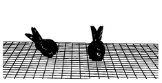
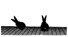
- the printing model on the left is the object that uses the above steps to achieve vertical printing
- the printing model on the right is the object printed by the conventional method. It is not difficult to find that the printing effect printed by this method is the best. Therefore, this method beneficial effect has been confirmed.
- FIG. 5 is a schematic block diagram of an apparatus for automatically improving a printing effect provided by an embodiment of the present invention.
- the present invention also provides a device for automatically improving the printing effect.
- the apparatus for automatically improving the printing effect includes a unit for executing the above-mentioned method for automatically improving the printing effect, and the apparatus can be configured in a terminal such as a printer, a desktop computer, a tablet computer, a laptop computer, and the like.
- the present invention also provides a device 200 for automatically improving printing effect, including the following units:
- a coordinate establishing unit 201 used for establishing a spatial coordinate system about the 3D printer
- a model parsing unit 202 configured to receive a 3D model import request, and parse triangular patches contained in the 3D model;
- the parameter obtaining unit 203 is used to obtain all the corner vertices of the three-dimensional model according to the triangular facets, use the maximum angular vertices to subtract the minimum angular vertices to obtain the bounding box of the three-dimensional model and the center point of the three-dimensional model, and create the center point according to the center point. perpendicular to the axis of the bounding box;
- the angle conversion unit 204 is configured to receive a platform inclination angle definition request of the 3D printer, and use the axis and the platform inclination angle to calculate the quaternion about the rotation of the three-dimensional model;
- the rotation implementation unit 205 is used for obtaining a rotation matrix according to the quaternion, multiplying the space matrix of the bounding box of the three-dimensional model and the rotation matrix to obtain the space matrix of the bounding box after rotation, and using 3D printing software to perform a slicing operation , so that the print path is perpendicular to the bounding box.
- the parameter obtaining unit 203 further includes a space matrix obtaining unit 2031, and the space matrix obtaining unit 2031 is configured to calculate the space matrix of the bounding box based on the space coordinate system.
- the angle conversion unit 204 further includes a quaternion parameter definition unit 2041, and the quaternion parameter definition unit 2041 is used to make the quaternion in turn by the cosine value of the tilt angle of the platform, the axis X coordinate and the tilt angle of the platform.
- the product of the sine value, the product of the sine value of the axis Y coordinate and the tilt angle of the platform, and the product of the sine value of the axis Z coordinate and the tilt angle of the platform are taken as real numbers.
- the rotation realization unit 205 further includes a rotation matrix derivation unit 2051, and the rotation matrix derivation unit 2051 is configured to obtain a rotation matrix by quaternion derivation.
- the above-mentioned apparatus for automatically enhancing the printing effect can be implemented in the form of a computer program, and the computer program can be executed on the computer device as shown in FIG. 6 .
- FIG. 6 is a schematic block diagram of a computer device provided by an embodiment of the present application.
- the computer device 300 may be a server, wherein the server may be an independent server or a server cluster composed of multiple servers.
- the computer device 300 includes a processor 302 , a memory and a network interface 305 connected through a system bus 301 , wherein the memory may include a non-volatile storage medium 303 and an internal memory 304 .
- the nonvolatile storage medium 303 can store an operating system 3031 and a computer program 3032 .
- the computer program 3032 includes program instructions, which, when executed, can cause the processor 302 to execute a method for automatically improving the printing effect.
- the processor 302 is used to provide computing and control capabilities to support the operation of the entire computer device 300 .
- the internal memory 304 provides an environment for running the computer program 3032 in the non-volatile storage medium 303.
- the processor 302 can execute a method for automatically improving the printing effect.
- the network interface 305 is used for network communication with other devices.
- the structure shown in FIG. 5 is only a block diagram of a partial structure related to the solution of the present application, and does not constitute a limitation on the computer device 300 to which the solution of the present application is applied.
- the specific computer device 300 may include more or fewer components than shown, or combine certain components, or have a different arrangement of components.
- processor 302 is used to run the computer program 3032 stored in the memory to realize the following steps:
- the processor 302 realizes the establishment of a spatial coordinate system related to the 3D printer; receives a request for importing a 3D model, and parses the triangular facets contained in the 3D model; obtains all corner tops of the 3D model according to the The corner vertex is subtracted from the minimum angle vertex to obtain the bounding box of the 3D model and the center point of the 3D model, and an axis perpendicular to the bounding box is created according to the center point; the platform inclination angle definition request from the 3D printer is received, and the axis and the platform are used.
- the printing software performs the slicing operation so that the printing path is perpendicular to the bounding box.
- the processor 302 may be a central processing unit (Central Processing Unit, CPU), and the processor 302 may also be other general-purpose processors, digital signal processors (Digital Signal Processor, DSP), Application Specific Integrated Circuit (ASIC), Field-Programmable Gate Array (FPGA) or other programmable logic devices, discrete gate or transistor logic devices, discrete hardware components, etc.
- the general-purpose processor can be a microprocessor or the processor can also be any conventional processor or the like.
- the computer program includes program instructions, and the computer program can be stored in a storage medium, and the storage medium is a computer-readable storage medium.
- the program instructions are executed by at least one processor in the computer system to implement the flow steps of the above-described method embodiments. Therefore, the present invention also provides a storage medium.
- the storage medium may be a computer-readable storage medium.
- the storage medium stores a computer program, wherein the computer program includes program instructions. The program instructions, when executed by the processor, cause the processor to perform the following steps:
- the processor executes the program instructions to realize the establishment of a spatial coordinate system related to the 3D printer; receives a request for importing a 3D model, parses the triangular facets contained in the 3D model; obtains the 3D model according to the triangular facets All corner tops of the 3D model are obtained by subtracting the minimum corner top from the maximum corner top to obtain the bounding box of the 3D model and the center point of the three-dimensional model, and create an axis perpendicular to the bounding box according to the center point; receive the platform inclination angle definition request from the 3D printer , use the axis and the tilt angle of the platform to calculate the quaternion about the rotation of the three-dimensional model; obtain the rotation matrix according to the quaternion, and multiply the space matrix of the bounding box of the three-dimensional model with the rotation matrix to obtain the rotation matrix after the rotation.
- the space matrix of the box is sliced by 3D printing software, so that the printing path is perpendicular to the bounding box.
- the storage medium may be various computer-readable storage media that can store program codes, such as a U disk, a removable hard disk, a read-only memory (Read-Only Memory, ROM), a magnetic disk, or an optical disk.
- program codes such as a U disk, a removable hard disk, a read-only memory (Read-Only Memory, ROM), a magnetic disk, or an optical disk.
- the disclosed apparatus and method may be implemented in other manners.
- the apparatus embodiments described above are merely illustrative.
- the division of each unit is only a logical function division, and other division methods may be used in actual implementation.
- multiple units or components may be combined or may be integrated into another system, or some features may be omitted, or not implemented.
- each functional unit in each embodiment of the present invention may be integrated into one processing unit, or each unit may exist physically alone, or two or more units may be integrated into one unit.
- the integrated unit if implemented in the form of a software functional unit and sold or used as an independent product, may be stored in a storage medium.
- the technical solution of the present invention is essentially or a part that contributes to the prior art, or all or part of the technical solution can be embodied in the form of a software product, and the computer software product is stored in a storage medium , including several instructions to cause a computer device (which may be a personal computer, a terminal, or a network device, etc.) to execute all or part of the steps of the methods described in the various embodiments of the present invention.
Landscapes
- Engineering & Computer Science (AREA)
- Materials Engineering (AREA)
- Chemical & Material Sciences (AREA)
- Manufacturing & Machinery (AREA)
- Physics & Mathematics (AREA)
- Optics & Photonics (AREA)
- Mechanical Engineering (AREA)
- Geometry (AREA)
- Theoretical Computer Science (AREA)
- General Physics & Mathematics (AREA)
- Mathematical Analysis (AREA)
- Computer Hardware Design (AREA)
- Evolutionary Computation (AREA)
- General Engineering & Computer Science (AREA)
- Pure & Applied Mathematics (AREA)
- Mathematical Optimization (AREA)
- Computational Mathematics (AREA)
Abstract
Description
本发明涉及3D打印技术领域,尤其涉及一种自动提升打印效果的方法、装置、设备及存储介质。The present invention relates to the technical field of 3D printing, and in particular, to a method, device, device and storage medium for automatically improving printing effect.
随着3D打印技术的发展,越来越多企业和个人都开始使用3D打印技术来生产设计自己的产品。常规的3D打印机的打印空间有限,打印模型大小也受限,现市面上流行有3D打印机,其可以打印无限长的模型。但是因为3D打印机将Z轴倒置,因此打印的模型存在一定的倾斜角度,会导致打印效果不如常规打印机,该问题是当前急需解决的问题。With the development of 3D printing technology, more and more companies and individuals have begun to use 3D printing technology to produce and design their own products. The printing space of conventional 3D printers is limited, and the size of the printed model is also limited. There are now popular 3D printers on the market, which can print infinitely long models. However, because the 3D printer inverts the Z axis, the printed model has a certain inclination angle, which will cause the printing effect to be inferior to that of conventional printers. This problem is an urgent problem to be solved at present.
公开于该背景技术部分的信息仅仅旨在加深对本发明的总体背景技术的理解,而不应当被视为承认或以任何形式暗示该信息构成已为本领域技术人员所公知的现有技术。The information disclosed in this Background section is only for enhancement of understanding of the general background of the invention and should not be taken as an acknowledgement or any form of suggestion that this information forms the prior art already known to a person skilled in the art.
发明内容SUMMARY OF THE INVENTION
本发明实施例提供了一种自动提升打印效果的方法、装置、设备及存储介质,旨在根据打印机平台倾斜角度,自动调整模型的倾斜角度,使模型仍然可以达到常规打印机垂直打印的效果,实现打印效果提升的目的。The embodiments of the present invention provide a method, device, device and storage medium for automatically improving the printing effect, aiming to automatically adjust the inclination angle of the model according to the inclination angle of the printer platform, so that the model can still achieve the effect of vertical printing by a conventional printer, and realize The purpose of improving the printing effect.
第一方面,本发明实施例提供了一种自动提升打印效果的方法,应用于3D打印机,包括以下步骤:In the first aspect, an embodiment of the present invention provides a method for automatically improving a printing effect, which is applied to a 3D printer and includes the following steps:
建立关于3D打印机的空间坐标系;Establish a spatial coordinate system about the 3D printer;
接收三维模型导入请求,解析三维模型含有的三角面片;Receive a 3D model import request, and parse the triangular patches contained in the 3D model;
根据所述三角面片获取三维模型的所有角顶,利用最大角顶减去最小角顶求出三维模型的包围盒以及三维模型的中心点,根据所述中心点创建垂直于包围盒的轴线;Obtain all the corner vertices of the 3D model according to the triangular patch, use the maximum angular vertices minus the minimum angular vertices to obtain the bounding box of the 3D model and the center point of the 3D model, and create an axis perpendicular to the bounding box according to the center point;
接收3D打印机的平台倾斜角度定义请求,利用所述轴线以及平台倾斜角度计算关于三维模型旋转的四元数;Receive the platform tilt angle definition request from the 3D printer, and use the axis and the platform tilt angle to calculate the quaternion about the rotation of the 3D model;
根据所述四元数得出旋转矩阵,将三维模型的包围盒的空间矩阵与旋转矩阵相乘,得到旋转之后的包围盒的空间矩阵,利用3D打印软件进行切片操作, 使打印路径垂直于包围盒。The rotation matrix is obtained according to the quaternion, and the space matrix of the bounding box of the three-dimensional model is multiplied by the rotation matrix to obtain the space matrix of the bounding box after rotation, and the slicing operation is performed by using the 3D printing software, so that the printing path is perpendicular to the surrounding box. box.
在一个可能的实施方式中,所述接收三维模型导入请求的步骤之前还包括,建立关于3D打印机的空间坐标系。In a possible implementation manner, before the step of receiving a request for importing a 3D model, the step further includes establishing a space coordinate system related to the 3D printer.
在一个可能的实施方式中,所述利用最大角顶减去最小角顶求出三维模型的包围盒以及三维模型的中心点的步骤还包括,计算基于空间坐标系的包围盒的空间矩阵。In a possible implementation manner, the step of obtaining the bounding box of the three-dimensional model and the center point of the three-dimensional model by using the maximum angle vertex minus the minimum angle vertex further includes calculating a space matrix of the bounding box based on the space coordinate system.
在一个可能的实施方式中,所述利用所述轴线以及平台倾斜角度计算关于三维模型旋转的四元数的步骤包括,使所述四元数依次以平台倾斜角度的余弦值、轴线X坐标与平台倾斜角度的正弦值乘积、轴线Y坐标与平台倾斜角度的正弦值乘积、轴线Z坐标与平台倾斜角度的正弦值乘积作为实数。In a possible implementation manner, the step of using the axis and the tilt angle of the platform to calculate the quaternion about the rotation of the three-dimensional model includes: making the quaternion sequentially use the cosine value of the tilt angle of the platform, the axis X coordinate and the The product of the sine value of the tilt angle of the platform, the product of the sine value of the axis Y coordinate and the tilt angle of the platform, and the product of the sine value of the axis Z coordinate and the tilt angle of the platform are taken as real numbers.
在一个可能的实施方式中,所述根据所述四元数得出旋转矩阵的步骤包括,由四元数推导获得旋转矩阵。In a possible implementation manner, the step of deriving the rotation matrix according to the quaternion includes obtaining the rotation matrix by deriving the quaternion.
在另一个方面,本发明还提供了一种自动提升打印效果的装置,包括以下单元:In another aspect, the present invention also provides a device for automatically improving the printing effect, comprising the following units:
坐标建立单元,用于建立关于3D打印机的空间坐标系;The coordinate establishment unit is used to establish the spatial coordinate system of the 3D printer;
模型解析单元,用于接收三维模型导入请求,解析三维模型含有的三角面片;The model parsing unit is used to receive a 3D model import request and parse the triangular facets contained in the 3D model;
参数获取单元,用于根据所述三角面片获取三维模型的所有角顶,利用最大角顶减去最小角顶求出三维模型的包围盒以及三维模型的中心点,根据所述中心点创建垂直于包围盒的轴线;The parameter obtaining unit is used to obtain all the corner vertices of the three-dimensional model according to the triangular patch, use the maximum angular vertices to subtract the minimum angular vertices to obtain the bounding box of the 3-D model and the center point of the three-dimensional model, and create a vertical axis according to the center point. on the axis of the bounding box;
角度转换单元,用于接收3D打印机的平台倾斜角度定义请求,利用所述轴线以及平台倾斜角度计算关于三维模型旋转的四元数;An angle conversion unit, configured to receive a platform inclination angle definition request from the 3D printer, and use the axis and the platform inclination angle to calculate a quaternion about the rotation of the three-dimensional model;
旋转实现单元,用于根据所述四元数得出旋转矩阵,将三维模型的包围盒的空间矩阵与旋转矩阵相乘,得到旋转之后的包围盒的空间矩阵,利用3D打印软件进行切片操作,使打印路径垂直于包围盒。The rotation realization unit is used to obtain the rotation matrix according to the quaternion, multiply the space matrix of the bounding box of the three-dimensional model with the rotation matrix, obtain the space matrix of the bounding box after rotation, and use the 3D printing software to perform the slicing operation, Make the print path normal to the bounding box.
在一个可能的实施方式中,所述参数获取单元还包括空间矩阵获取单元,所述空间矩阵获取单元用于计算基于空间坐标系的包围盒的空间矩阵。In a possible implementation manner, the parameter obtaining unit further includes a space matrix obtaining unit, and the space matrix obtaining unit is configured to calculate the space matrix of the bounding box based on the space coordinate system.
在一个可能的实施方式中,所述角度转换单元还包括四元数参数定义单元,所述四元数参数定义单元用于使所述四元数依次以平台倾斜角度的余弦值、轴线X坐标与平台倾斜角度的正弦值乘积、轴线Y坐标与平台倾斜角度的正弦值 乘积、轴线Z坐标与平台倾斜角度的正弦值乘积作为实数。In a possible implementation manner, the angle conversion unit further includes a quaternion parameter definition unit, the quaternion parameter definition unit is configured to make the quaternion successively use the cosine value of the tilt angle of the platform, the axis X coordinate The product of the sine value of the tilt angle of the platform, the product of the sine value of the axis Y coordinate and the tilt angle of the platform, and the product of the sine value of the axis Z coordinate and the tilt angle of the platform are taken as real numbers.
在一个可能的实施方式中,所述旋转实现单元还包括旋转矩阵推导单元,所述旋转矩阵推导单元用于由四元数推导获得旋转矩阵。在第三方面,本发明提供了一种计算机设备,所述计算机设备包括存储器及处理器,所述存储器上存储有计算机程序,所述处理器执行所述计算机程序时实现如上述任一项所述的自动提升打印效果的方法。In a possible implementation, the rotation realization unit further includes a rotation matrix derivation unit, the rotation matrix derivation unit is configured to obtain the rotation matrix by quaternion derivation. In a third aspect, the present invention provides a computer device, the computer device includes a memory and a processor, the memory stores a computer program, and when the processor executes the computer program, any one of the above-mentioned methods is implemented. The method described above to automatically improve the printing effect.
在第四方面,本发明提供了一种存储介质,所述存储介质存储有计算机程序,所述计算机程序包括程序指令,所述程序指令当被处理器执行时可实现如上述任一项所述的自动提升打印效果的方法。In a fourth aspect, the present invention provides a storage medium, where the storage medium stores a computer program, the computer program includes program instructions, and the program instructions, when executed by a processor, can implement any of the above The method of automatically improving the printing effect.
相比于现有技术,本发明的有益效果在于:通过接收三维模型导入请求,解析三维模型含有的三角面片,根据所述三角面片获取三维模型的所有角顶,利用最大角顶减去最小角顶求出三维模型的包围盒以及三维模型的中心点,根据所述中心点创建垂直于包围盒的轴线;接收3D打印机的平台倾斜角度定义请求,利用所述轴线以及平台倾斜角度计算关于三维模型旋转的四元数;根据所述四元数得出旋转矩阵,将三维模型的包围盒的空间矩阵与旋转矩阵相乘,得到旋转之后的包围盒的空间矩阵,利用3D打印软件进行切片操作,使打印路径垂直于包围盒。实现了导入模型即自动与平台保持一致的倾斜角度,对于当前市场风靡的Z轴无限打印机的打印效果提升,具有较佳的经济价值。Compared with the prior art, the beneficial effect of the present invention is: by receiving a request for importing a three-dimensional model, analyzing the triangular patches contained in the three-dimensional model, obtaining all the corner vertices of the three-dimensional model according to the triangular patches, and subtracting the maximum corner vertex by subtracting The minimum angle vertex obtains the bounding box of the three-dimensional model and the center point of the three-dimensional model, and creates an axis perpendicular to the bounding box according to the center point; receives the platform inclination angle definition request of the 3D printer, and uses the axis and the platform inclination angle to calculate about The quaternion of the rotation of the three-dimensional model; the rotation matrix is obtained according to the quaternion, and the space matrix of the bounding box of the three-dimensional model is multiplied by the rotation matrix to obtain the space matrix of the bounding box after rotation, and the 3D printing software is used for slicing. Operate so that the print path is perpendicular to the bounding box. It realizes the inclination angle that is automatically consistent with the platform after importing the model, and has better economic value for the improvement of the printing effect of the Z-axis infinite printer that is currently popular in the market.
下面结合附图和具体实施例对本发明作进一步描述。The present invention will be further described below with reference to the accompanying drawings and specific embodiments.
为了更清楚地说明本发明实施例技术方案,下面将对实施例描述中所需要使用的附图作简单地介绍,显而易见地,下面描述中的附图是本发明的一些实施例,对于本领域普通技术人员来讲,在不付出创造性劳动的前提下,还可以根据这些附图获得其他的附图。In order to explain the technical solutions of the embodiments of the present invention more clearly, the following briefly introduces the accompanying drawings used in the description of the embodiments. Obviously, the drawings in the following description are some embodiments of the present invention, which are of great significance to the art For those of ordinary skill, other drawings can also be obtained from these drawings without any creative effort.
图1为本发明实施例提供的自动提升打印效果的方法的应用场景示意图;1 is a schematic diagram of an application scenario of a method for automatically improving a printing effect provided by an embodiment of the present invention;
图2为本发明实施例提供的自动提升打印效果的方法的另一应用场景示意图;2 is a schematic diagram of another application scenario of the method for automatically improving a printing effect provided by an embodiment of the present invention;
图3为本发明实施例提供的自动提升打印效果的方法的另一应用场景示意图;3 is a schematic diagram of another application scenario of the method for automatically improving a printing effect provided by an embodiment of the present invention;
图4为本发明实施例提供的自动提升打印效果的方法的流程示意图;4 is a schematic flowchart of a method for automatically improving a printing effect provided by an embodiment of the present invention;
图5为本发明实施例提供的自动提升打印效果的装置的示意性框图;5 is a schematic block diagram of an apparatus for automatically improving a printing effect provided by an embodiment of the present invention;
图6为本发明实施例提供的计算机设备的示意性框图。FIG. 6 is a schematic block diagram of a computer device according to an embodiment of the present invention.
下面将结合本发明实施例中的附图,对本发明实施例中的技术方案进行清楚、完整地描述,显然,所描述的实施例是本发明一部分实施例,而不是全部的实施例。基于本发明中的实施例,本领域普通技术人员在没有做出创造性劳动前提下所获得的所有其他实施例,都属于本发明保护的范围。The technical solutions in the embodiments of the present invention will be clearly and completely described below with reference to the accompanying drawings in the embodiments of the present invention. Obviously, the described embodiments are part of the embodiments of the present invention, but not all of the embodiments. Based on the embodiments of the present invention, all other embodiments obtained by those of ordinary skill in the art without creative efforts shall fall within the protection scope of the present invention.
应当理解,当在本说明书和所附权利要求书中使用时,术语“包括”和“包含”指示所描述特征、整体、步骤、操作、元素和/或组件的存在,但并不排除一个或多个其它特征、整体、步骤、操作、元素、组件和/或其集合的存在或添加。It is to be understood that, when used in this specification and the appended claims, the terms "comprising" and "comprising" indicate the presence of the described features, integers, steps, operations, elements and/or components, but do not exclude one or The presence or addition of a number of other features, integers, steps, operations, elements, components, and/or sets thereof.
还应当理解,在此本发明说明书中所使用的术语仅仅是出于描述特定实施例的目的而并不意在限制本发明。如在本发明说明书和所附权利要求书中所使用的那样,除非上下文清楚地指明其它情况,否则单数形式的“一”、“一个”及“该”意在包括复数形式。It is also to be understood that the terminology used in this specification of the present invention is for the purpose of describing particular embodiments only and is not intended to limit the present invention. As used in this specification and the appended claims, the singular forms "a," "an," and "the" are intended to include the plural unless the context clearly dictates otherwise.
还应当进一步理解,在本发明说明书和所附权利要求书中使用的术语“和/或”是指相关联列出的项中的一个或多个的任何组合以及所有可能组合,并且包括这些组合。It should further be understood that, as used in this specification and the appended claims, the term "and/or" refers to and including any and all possible combinations of one or more of the associated listed items .
请参阅图1、图2、图3以及图4,图1-3均为本发明实施例提供的自动提升打印效果的方法的应用场景示意图;图4为本发明实施例提供的自动提升打印效果的方法的流程示意图。如图所示,本发明的自动提升打印效果的方法应用于3D打印机,该方法通过安装于3D打印机中的计算机程序进行执行,3D打印机与用户端进行数据交互,用户端可以是具有信息接收功能及信息发送功能的用户端设备,例如台式电脑、笔记本电脑、平板电脑或智能手机等,3D打印机可以从用户端获取三维模型数据以实现打印。如图4所示,本发明实施例提供的一种自动提升打印效果的方法,包括以下步骤:Please refer to FIG. 1 , FIG. 2 , FIG. 3 , and FIG. 4 . FIGS. 1-3 are schematic diagrams of application scenarios of the method for automatically improving the printing effect provided by the embodiment of the present invention; FIG. 4 is the automatically improving printing effect provided by the embodiment of the present invention. Schematic flow diagram of the method. As shown in the figure, the method for automatically improving the printing effect of the present invention is applied to a 3D printer. The method is executed by a computer program installed in the 3D printer. The 3D printer interacts with the user terminal, and the user terminal may have the function of receiving information. 3D printers can obtain 3D model data from the user side for printing. As shown in FIG. 4 , a method for automatically improving a printing effect provided by an embodiment of the present invention includes the following steps:
步骤S101、建立关于3D打印机的空间坐标系;Step S101, establishing a spatial coordinate system about the 3D printer;
步骤S102、接收三维模型导入请求,解析三维模型含有的三角面片;Step S102, receiving a three-dimensional model import request, and analyzing the triangular facets contained in the three-dimensional model;
在本实施例中,由于需要实现导入模型即自动与平台保持一致的倾斜角度,因此,需要建立坐标系为倾斜角度创建对照物,步骤S101建立关于3D打印机的空间坐标系,所述空间坐标系可为X-Y-Z坐标系。其中,三维模型包括但不限于STL格式的模型文件。In this embodiment, since it is necessary to realize the inclination angle of importing the model, that is, to automatically maintain the same inclination angle with the platform, it is necessary to establish a coordinate system to create a reference object for the inclination angle. Step S101 establishes a spatial coordinate system about the 3D printer. The spatial coordinate system Can be an X-Y-Z coordinate system. Wherein, the three-dimensional model includes but is not limited to a model file in STL format.
步骤S103、根据所述三角面片获取三维模型的所有角顶,利用最大角顶减去最小角顶求出三维模型的包围盒以及三维模型的中心点,根据所述中心点创建垂直于包围盒的轴线;Step S103: Obtain all the corner vertices of the three-dimensional model according to the triangular patch, use the maximum angular vertices minus the minimum angular vertices to obtain the bounding box of the three-dimensional model and the center point of the three-dimensional model, and create a bounding box perpendicular to the center point according to the center point. axis;
在本实施例中,所述利用最大角顶减去最小角顶求出三维模型的包围盒以及三维模型的中心点的步骤还包括,计算基于空间坐标系的包围盒的空间矩阵,由于待打印的三维模型需要以数据化的形式在3D打印机以实现读取以及打印输出,因此,在本例中,采用空间矩阵的形式对模型进行处理。In this embodiment, the step of obtaining the bounding box of the 3D model and the center point of the 3D model by subtracting the minimum angular vertex from the maximum angular vertex further includes: calculating the spatial matrix of the bounding box based on the spatial coordinate system, because the to-be-printed The 3D model needs to be read and printed out on the 3D printer in the form of data. Therefore, in this example, the model is processed in the form of a space matrix.
在某些实施例中,所述空间矩阵的数量可为若干,以相关联的组合方式共同构成三维模型,以便于打印机进行处理数据。In some embodiments, the number of the space matrices can be several, and the three-dimensional model is formed together in an associated combination manner, so that the printer can process the data.
步骤S104、接收3D打印机的平台倾斜角度定义请求,利用所述轴线以及平台倾斜角度计算关于三维模型旋转的四元数;Step S104, receiving the platform tilt angle definition request of the 3D printer, and using the axis and the platform tilt angle to calculate the quaternion about the rotation of the three-dimensional model;
在本实施例中,所述四元数为描述三维空间中位姿的方式,四元数是由实数加上虚数单位i组成,其中i^2=-1。相似地,四元数都是由实数加上三个虚数单位i、j、k组成,而且它们有如下的关系:i^2=j^2=k^2=-1,i^0=j^0=k^0=1,每个四元数都是1、i、j和k的线性组合,即是四元数一般可表示为a+bi+cj+dk,其中a、b、c、d是实数。因此,在本实施例中,所述四元数依次以平台倾斜角度的余弦值、轴线X坐标与平台倾斜角度的正弦值乘积、轴线Y坐标与平台倾斜角度的正弦值乘积、轴线Z坐标与平台倾斜角度的正弦值乘积作为实数,以便于精确地实现旋转角度的计算。In this embodiment, the quaternion is a way of describing the pose in the three-dimensional space, and the quaternion is composed of a real number plus an imaginary unit i, where i^2=-1. Similarly, quaternions are composed of real numbers plus three imaginary units i, j, and k, and they have the following relationship: i^2=j^2=k^2=-1, i^0=j ^0=k^0=1, each quaternion is a linear combination of 1, i, j and k, that is, the quaternion can generally be expressed as a+bi+cj+dk, where a, b, c , d is a real number. Therefore, in this embodiment, the quaternion is sequentially calculated by the cosine value of the tilt angle of the platform, the product of the sine value of the axis X coordinate and the tilt angle of the platform, the product of the sine value of the axis Y coordinate and the tilt angle of the platform, the axis Z coordinate and The product of the sine values of the tilt angle of the platform is used as a real number to facilitate the calculation of the rotation angle accurately.
步骤S105、根据所述四元数得出旋转矩阵,将三维模型的包围盒的空间矩阵与旋转矩阵相乘,得到旋转之后的包围盒的空间矩阵,利用3D打印软件进行切片操作,使打印路径垂直于包围盒。Step S105, obtaining a rotation matrix according to the quaternion, multiplying the space matrix of the bounding box of the three-dimensional model by the rotation matrix to obtain the space matrix of the bounding box after rotation, and using 3D printing software to perform a slicing operation to make the printing path. perpendicular to the bounding box.
其中,得到旋转之后的包围盒的空间矩阵需要运用于3D打印机进行源数据读取,作为待打印模型。Among them, the space matrix of the rotated bounding box needs to be applied to the 3D printer to read the source data as the model to be printed.
在某些实施例中,可由四元数推导获得旋转矩阵,其中推导过程可参考现有技术(如CSDN论坛中相关“四元数和旋转矩阵的相互推导过程”)实现,本处不做赘述。In some embodiments, the rotation matrix can be obtained by quaternion derivation, and the derivation process can be implemented with reference to the prior art (such as the related "mutual derivation process of quaternion and rotation matrix" in the CSDN forum), which will not be repeated here. .
结合图1-图3,左边的打印模型即利用上述步骤实现垂直打印的物体,右边的打印模型为常规方法打印的物体,不难发现,采用本方法打印的打印效果最佳,因此,本方法的有益效果得到证实。1-3, the printing model on the left is the object that uses the above steps to achieve vertical printing, and the printing model on the right is the object printed by the conventional method. It is not difficult to find that the printing effect printed by this method is the best. Therefore, this method beneficial effect has been confirmed.
图5是本发明实施例提供的一种自动提升打印效果的装置的示意性框图。 如图5所示,对应于以上自动提升打印效果的方法,本发明还提供一种自动提升打印效果的装置。该自动提升打印效果的装置包括用于执行上述自动提升打印效果的方法的单元,该装置可以被配置于打印机、台式电脑、平板电脑、手提电脑等终端中。具体地,请参阅图5,本发明还提供了一种自动提升打印效果的装置200,包括以下单元:FIG. 5 is a schematic block diagram of an apparatus for automatically improving a printing effect provided by an embodiment of the present invention. As shown in FIG. 5 , corresponding to the above method for automatically improving the printing effect, the present invention also provides a device for automatically improving the printing effect. The apparatus for automatically improving the printing effect includes a unit for executing the above-mentioned method for automatically improving the printing effect, and the apparatus can be configured in a terminal such as a printer, a desktop computer, a tablet computer, a laptop computer, and the like. Specifically, referring to FIG. 5 , the present invention also provides a
坐标建立单元201,用于建立关于3D打印机的空间坐标系;a coordinate establishing
模型解析单元202,用于接收三维模型导入请求,解析三维模型含有的三角面片;A
参数获取单元203,用于根据所述三角面片获取三维模型的所有角顶,利用最大角顶减去最小角顶求出三维模型的包围盒以及三维模型的中心点,根据所述中心点创建垂直于包围盒的轴线;The
角度转换单元204,用于接收3D打印机的平台倾斜角度定义请求,利用所述轴线以及平台倾斜角度计算关于三维模型旋转的四元数;The
旋转实现单元205,用于根据所述四元数得出旋转矩阵,将三维模型的包围盒的空间矩阵与旋转矩阵相乘,得到旋转之后的包围盒的空间矩阵,利用3D打印软件进行切片操作,使打印路径垂直于包围盒。The
其中,所述参数获取单元203还包括空间矩阵获取单元2031,所述空间矩阵获取单元2031用于计算基于空间坐标系的包围盒的空间矩阵。所述角度转换单元204还包括四元数参数定义单元2041,所述四元数参数定义单元2041用于使所述四元数依次以平台倾斜角度的余弦值、轴线X坐标与平台倾斜角度的正弦值乘积、轴线Y坐标与平台倾斜角度的正弦值乘积、轴线Z坐标与平台倾斜角度的正弦值乘积作为实数。所述旋转实现单元205还包括旋转矩阵推导单元2051,所述旋转矩阵推导单元2051用于由四元数推导获得旋转矩阵。The
需要说明的是,所属领域的技术人员可以清楚地了解到,上述自动提升打印效果的装置200和各单元的具体实现过程,可以参考前述方法实施例中的相应描述,为了描述的方便和简洁,在此不再赘述。It should be noted that those skilled in the art can clearly understand that, for the specific implementation process of the above-mentioned
上述自动提升打印效果的装置可以实现为一种计算机程序的形式,该计算机程序可以在如图6所示的计算机设备上运行。The above-mentioned apparatus for automatically enhancing the printing effect can be implemented in the form of a computer program, and the computer program can be executed on the computer device as shown in FIG. 6 .
请参阅图6,图6是本申请实施例提供的一种计算机设备的示意性框图。该计算机设备300可以是服务器,其中,服务器可以是独立的服务器,也可以是 多个服务器组成的服务器集群。Please refer to FIG. 6, which is a schematic block diagram of a computer device provided by an embodiment of the present application. The
参阅图6,该计算机设备300包括通过系统总线301连接的处理器302、存储器和网络接口305,其中,存储器可以包括非易失性存储介质303和内存储器304。Referring to FIG. 6 , the
该非易失性存储介质303可存储操作系统3031和计算机程序3032。该计算机程序3032包括程序指令,该程序指令被执行时,可使得处理器302执行一种自动提升打印效果的方法。The
该处理器302用于提供计算和控制能力,以支撑整个计算机设备300的运行。The
该内存储器304为非易失性存储介质303中的计算机程序3032的运行提供环境,该计算机程序3032被处理器302执行时,可使得处理器302执行一种自动提升打印效果的方法。The
该网络接口305用于与其它设备进行网络通信。本领域技术人员可以理解,图5中示出的结构,仅仅是与本申请方案相关的部分结构的框图,并不构成对本申请方案所应用于其上的计算机设备300的限定,具体的计算机设备300可以包括比图中所示更多或更少的部件,或者组合某些部件,或者具有不同的部件布置。The
其中,所述处理器302用于运行存储在存储器中的计算机程序3032,以实现如下步骤:Wherein, the
在一实施例中,处理器302实现建立关于3D打印机的空间坐标系;接收三维模型导入请求,解析三维模型含有的三角面片;根据所述三角面片获取三维模型的所有角顶,利用最大角顶减去最小角顶求出三维模型的包围盒以及三维模型的中心点,根据所述中心点创建垂直于包围盒的轴线;接收3D打印机的平台倾斜角度定义请求,利用所述轴线以及平台倾斜角度计算关于三维模型旋转的四元数;根据所述四元数得出旋转矩阵,将三维模型的包围盒的空间矩阵与旋转矩阵相乘,得到旋转之后的包围盒的空间矩阵,利用3D打印软件进行切片操作,使打印路径垂直于包围盒。In one embodiment, the
应当理解,在本申请实施例中,处理器302可以是中央处理单元(Central Processing Unit,CPU),该处理器302还可以是其他通用处理器、数字信号处理器(Digital Signal Processor,DSP)、专用集成电路(Application Specific Integrated Circuit,ASIC)、现成可编程门阵列(Field-Programmable Gate Array,FPGA)或 者其他可编程逻辑器件、分立门或者晶体管逻辑器件、分立硬件组件等。其中,通用处理器可以是微处理器或者该处理器也可以是任何常规的处理器等。It should be understood that, in this embodiment of the present application, the
本领域普通技术人员可以理解的是实现上述实施例的方法中的全部或部分流程,是可以通过计算机程序来指令相关的硬件来完成。该计算机程序包括程序指令,计算机程序可存储于一存储介质中,该存储介质为计算机可读存储介质。该程序指令被该计算机系统中的至少一个处理器执行,以实现上述方法的实施例的流程步骤。因此,本发明还提供一种存储介质。该存储介质可以为计算机可读存储介质。该存储介质存储有计算机程序,其中计算机程序包括程序指令。该程序指令被处理器执行时使处理器执行如下步骤:It can be understood by those skilled in the art that all or part of the processes in the methods for implementing the above embodiments can be completed by instructing relevant hardware through a computer program. The computer program includes program instructions, and the computer program can be stored in a storage medium, and the storage medium is a computer-readable storage medium. The program instructions are executed by at least one processor in the computer system to implement the flow steps of the above-described method embodiments. Therefore, the present invention also provides a storage medium. The storage medium may be a computer-readable storage medium. The storage medium stores a computer program, wherein the computer program includes program instructions. The program instructions, when executed by the processor, cause the processor to perform the following steps:
在一实施例中,所述处理器执行所述程序指令而实现建立关于3D打印机的空间坐标系;接收三维模型导入请求,解析三维模型含有的三角面片;根据所述三角面片获取三维模型的所有角顶,利用最大角顶减去最小角顶求出三维模型的包围盒以及三维模型的中心点,根据所述中心点创建垂直于包围盒的轴线;接收3D打印机的平台倾斜角度定义请求,利用所述轴线以及平台倾斜角度计算关于三维模型旋转的四元数;根据所述四元数得出旋转矩阵,将三维模型的包围盒的空间矩阵与旋转矩阵相乘,得到旋转之后的包围盒的空间矩阵,利用3D打印软件进行切片操作,使打印路径垂直于包围盒。In one embodiment, the processor executes the program instructions to realize the establishment of a spatial coordinate system related to the 3D printer; receives a request for importing a 3D model, parses the triangular facets contained in the 3D model; obtains the 3D model according to the triangular facets All corner tops of the 3D model are obtained by subtracting the minimum corner top from the maximum corner top to obtain the bounding box of the 3D model and the center point of the three-dimensional model, and create an axis perpendicular to the bounding box according to the center point; receive the platform inclination angle definition request from the 3D printer , use the axis and the tilt angle of the platform to calculate the quaternion about the rotation of the three-dimensional model; obtain the rotation matrix according to the quaternion, and multiply the space matrix of the bounding box of the three-dimensional model with the rotation matrix to obtain the rotation matrix after the rotation. The space matrix of the box is sliced by 3D printing software, so that the printing path is perpendicular to the bounding box.
所述存储介质可以是U盘、移动硬盘、只读存储器(Read-Only Memory,ROM)、磁碟或者光盘等各种可以存储程序代码的计算机可读存储介质。The storage medium may be various computer-readable storage media that can store program codes, such as a U disk, a removable hard disk, a read-only memory (Read-Only Memory, ROM), a magnetic disk, or an optical disk.
本领域普通技术人员可以意识到,结合本文中所公开的实施例描述的各示例的单元及算法步骤,能够以电子硬件、计算机软件或者二者的结合来实现,为了清楚地说明硬件和软件的可互换性,在上述说明中已经按照功能一般性地描述了各示例的组成及步骤。这些功能究竟以硬件还是软件方式来执行,取决于技术方案的特定应用和设计约束条件。专业技术人员可以对每个特定的应用来使用不同方法来实现所描述的功能,但是这种实现不应认为超出本发明的范围。Those of ordinary skill in the art can realize that the units and algorithm steps of each example described in conjunction with the embodiments disclosed herein can be implemented in electronic hardware, computer software, or a combination of the two, in order to clearly illustrate the differences between hardware and software Interchangeability, the above description has generally described the components and steps of each example in terms of function. Whether these functions are performed in hardware or software depends on the specific application and design constraints of the technical solution. Skilled artisans may implement the described functionality using different methods for each particular application, but such implementations should not be considered beyond the scope of the present invention.
在本发明所提供的几个实施例中,应该理解到,所揭露的装置和方法,可以通过其它的方式实现。例如,以上所描述的装置实施例仅仅是示意性的。例如,各个单元的划分,仅仅为一种逻辑功能划分,实际实现时可以有另外的划分方式。例如多个单元或组件可以结合或者可以集成到另一个系统,或一些特征可以忽略,或不执行。In the several embodiments provided by the present invention, it should be understood that the disclosed apparatus and method may be implemented in other manners. For example, the apparatus embodiments described above are merely illustrative. For example, the division of each unit is only a logical function division, and other division methods may be used in actual implementation. For example, multiple units or components may be combined or may be integrated into another system, or some features may be omitted, or not implemented.
本发明实施例方法中的步骤可以根据实际需要进行顺序调整、合并和删减。本发明实施例装置中的单元可以根据实际需要进行合并、划分和删减。另外,在本发明各个实施例中的各功能单元可以集成在一个处理单元中,也可以是各个单元单独物理存在,也可以是两个或两个以上单元集成在一个单元中。The steps in the method of the embodiment of the present invention may be adjusted, combined and deleted in sequence according to actual needs. Units in the apparatus of the embodiment of the present invention may be combined, divided, and deleted according to actual needs. In addition, each functional unit in each embodiment of the present invention may be integrated into one processing unit, or each unit may exist physically alone, or two or more units may be integrated into one unit.
该集成的单元如果以软件功能单元的形式实现并作为独立的产品销售或使用时,可以存储在一个存储介质中。基于这样的理解,本发明的技术方案本质上或者说对现有技术做出贡献的部分,或者该技术方案的全部或部分可以以软件产品的形式体现出来,该计算机软件产品存储在一个存储介质中,包括若干指令用以使得一台计算机设备(可以是个人计算机,终端,或者网络设备等)执行本发明各个实施例所述方法的全部或部分步骤。The integrated unit, if implemented in the form of a software functional unit and sold or used as an independent product, may be stored in a storage medium. Based on such understanding, the technical solution of the present invention is essentially or a part that contributes to the prior art, or all or part of the technical solution can be embodied in the form of a software product, and the computer software product is stored in a storage medium , including several instructions to cause a computer device (which may be a personal computer, a terminal, or a network device, etc.) to execute all or part of the steps of the methods described in the various embodiments of the present invention.
以上所述,仅为本发明的具体实施方式,但本发明的保护范围并不局限于此,任何熟悉本技术领域的技术人员在本发明揭露的技术范围内,可轻易想到各种等效的修改或替换,这些修改或替换都应涵盖在本发明的保护范围之内。因此,本发明的保护范围应以权利要求的保护范围为准。The above are only specific embodiments of the present invention, but the protection scope of the present invention is not limited to this. Any person skilled in the art can easily think of various equivalents within the technical scope disclosed by the present invention. Modifications or substitutions should be included within the protection scope of the present invention. Therefore, the protection scope of the present invention should be subject to the protection scope of the claims.
Claims (10)
Priority Applications (2)
| Application Number | Priority Date | Filing Date | Title |
|---|---|---|---|
| EP20956123.2A EP4223486A4 (en) | 2020-09-30 | 2020-12-28 | METHOD AND APPARATUS FOR AUTOMATICALLY IMPROVING PRINTING EFFECT, DEVICE AND RECORDING MEDIUM |
| US18/029,650 US12515411B2 (en) | 2020-09-30 | 2020-12-28 | Method and apparatus for automatically improving printing effect, device, and storage medium |
Applications Claiming Priority (2)
| Application Number | Priority Date | Filing Date | Title |
|---|---|---|---|
| CN202011058611.3A CN112172149B (en) | 2020-09-30 | 2020-09-30 | Method, device and equipment for automatically improving printing effect and storage medium |
| CN202011058611.3 | 2020-09-30 |
Publications (1)
| Publication Number | Publication Date |
|---|---|
| WO2022068107A1 true WO2022068107A1 (en) | 2022-04-07 |
Family
ID=73946219
Family Applications (1)
| Application Number | Title | Priority Date | Filing Date |
|---|---|---|---|
| PCT/CN2020/140125 Ceased WO2022068107A1 (en) | 2020-09-30 | 2020-12-28 | Method and apparatus for automatically improving printing effect, device, and storage medium |
Country Status (4)
| Country | Link |
|---|---|
| US (1) | US12515411B2 (en) |
| EP (1) | EP4223486A4 (en) |
| CN (1) | CN112172149B (en) |
| WO (1) | WO2022068107A1 (en) |
Families Citing this family (4)
| Publication number | Priority date | Publication date | Assignee | Title |
|---|---|---|---|---|
| CN113034382B (en) * | 2021-02-23 | 2024-04-30 | 深圳市创想三维科技股份有限公司 | Brightness uniformity adjustment method, brightness uniformity adjustment device, computer device, and readable storage medium |
| CN113836606A (en) * | 2021-09-07 | 2021-12-24 | 深圳市创想三帝科技有限公司 | Method, device and equipment for determining model supporting points and storage medium |
| CN114834043B (en) * | 2022-05-09 | 2023-09-05 | 华中科技大学鄂州工业技术研究院 | Laser three-dimensional processing model slice data processing method |
| CN119152159B (en) * | 2024-10-10 | 2025-03-11 | 南京衍构科技有限公司 | 3D printing rotating curved surface slicing method, system, equipment and storage medium |
Citations (13)
| Publication number | Priority date | Publication date | Assignee | Title |
|---|---|---|---|---|
| CN106780350A (en) * | 2016-11-30 | 2017-05-31 | 王征 | A kind of 3D model anglec of rotation Self Matching system and methods based on anglec of rotation model library |
| CN107089008A (en) * | 2017-06-29 | 2017-08-25 | 温州启龙电子科技有限公司 | A kind of 3D printer |
| CN107379530A (en) * | 2017-08-21 | 2017-11-24 | 华南理工大学 | Wrong path compensation device and method during FDM formula 3D printer platform inclinations |
| CN107798734A (en) * | 2017-12-07 | 2018-03-13 | 梦工场珠宝企业管理有限公司 | The adaptive deformation method of threedimensional model |
| CN108481741A (en) * | 2018-03-13 | 2018-09-04 | 珠海天威飞马打印耗材有限公司 | A kind of three-dimensional printer and 3 D-printing platform method of adjustment |
| WO2018194446A1 (en) * | 2017-04-18 | 2018-10-25 | Stephan Schürmann Holding B.V. | A gantry-type three dimensional printing apparatus for printing a three dimensional work piece in a layer wise manner |
| CN108846801A (en) * | 2018-06-12 | 2018-11-20 | 佛山欧神诺云商科技有限公司 | A kind of method and device thereof that model is adjusted by self-defining data |
| CN108973113A (en) * | 2018-10-09 | 2018-12-11 | 昆明学院 | 3D printing device and its Method of printing without support |
| CN109394410A (en) * | 2018-11-13 | 2019-03-01 | 武汉必盈生物科技有限公司 | Based on the personalized outer fixed 3D printing model design method of patient and slice systems |
| CN110154391A (en) * | 2019-06-27 | 2019-08-23 | 深圳市创想三维科技有限公司 | A kind of luminous advertisement word shell 3D printer and its Method of printing |
| CN209813079U (en) * | 2019-04-25 | 2019-12-20 | 郭登机 | Automatic 3D printer capable of printing infinite-length objects and reducing supporting structures |
| CN111347676A (en) * | 2020-04-16 | 2020-06-30 | 杭州喜马拉雅信息科技有限公司 | 3D print platform with adjustable angle |
| KR20200084931A (en) * | 2018-12-20 | 2020-07-14 | 이수빈 | 3d printer capable of continuous 3d printing |
Family Cites Families (9)
| Publication number | Priority date | Publication date | Assignee | Title |
|---|---|---|---|---|
| EP2011631B1 (en) * | 2007-07-04 | 2012-04-18 | Envisiontec GmbH | Process and device for producing a three-dimensional object |
| US8749556B2 (en) * | 2008-10-14 | 2014-06-10 | Mixamo, Inc. | Data compression for real-time streaming of deformable 3D models for 3D animation |
| DE102012022859A1 (en) * | 2012-11-25 | 2014-05-28 | Voxeljet Ag | Construction of a 3D printing device for the production of components |
| CN104085112B (en) * | 2014-07-11 | 2016-08-31 | 东莞中国科学院云计算产业技术创新与育成中心 | A kind of 3D printer head and speed and precision thereof regulate and control method |
| US10518473B2 (en) | 2015-07-31 | 2019-12-31 | Hewlett-Packard Development Company, L.P. | Parts arrangement determination for a 3D printer build envelope |
| JP6298035B2 (en) * | 2015-12-17 | 2018-03-20 | ファナック株式会社 | Model generation device, position and orientation calculation device, and handling robot device |
| WO2017106965A1 (en) * | 2015-12-21 | 2017-06-29 | Ord Solutions Inc. | Method and apparatus for large format three-dimensional printing |
| CN105904729B (en) * | 2016-04-22 | 2018-04-06 | 浙江大学 | It is a kind of based on incline cut and fill stoping without support 3 D-printing method |
| CN109496325A (en) * | 2016-07-29 | 2019-03-19 | 索尼公司 | Image processing apparatus and image processing method |
-
2020
- 2020-09-30 CN CN202011058611.3A patent/CN112172149B/en active Active
- 2020-12-28 US US18/029,650 patent/US12515411B2/en active Active
- 2020-12-28 WO PCT/CN2020/140125 patent/WO2022068107A1/en not_active Ceased
- 2020-12-28 EP EP20956123.2A patent/EP4223486A4/en active Pending
Patent Citations (13)
| Publication number | Priority date | Publication date | Assignee | Title |
|---|---|---|---|---|
| CN106780350A (en) * | 2016-11-30 | 2017-05-31 | 王征 | A kind of 3D model anglec of rotation Self Matching system and methods based on anglec of rotation model library |
| WO2018194446A1 (en) * | 2017-04-18 | 2018-10-25 | Stephan Schürmann Holding B.V. | A gantry-type three dimensional printing apparatus for printing a three dimensional work piece in a layer wise manner |
| CN107089008A (en) * | 2017-06-29 | 2017-08-25 | 温州启龙电子科技有限公司 | A kind of 3D printer |
| CN107379530A (en) * | 2017-08-21 | 2017-11-24 | 华南理工大学 | Wrong path compensation device and method during FDM formula 3D printer platform inclinations |
| CN107798734A (en) * | 2017-12-07 | 2018-03-13 | 梦工场珠宝企业管理有限公司 | The adaptive deformation method of threedimensional model |
| CN108481741A (en) * | 2018-03-13 | 2018-09-04 | 珠海天威飞马打印耗材有限公司 | A kind of three-dimensional printer and 3 D-printing platform method of adjustment |
| CN108846801A (en) * | 2018-06-12 | 2018-11-20 | 佛山欧神诺云商科技有限公司 | A kind of method and device thereof that model is adjusted by self-defining data |
| CN108973113A (en) * | 2018-10-09 | 2018-12-11 | 昆明学院 | 3D printing device and its Method of printing without support |
| CN109394410A (en) * | 2018-11-13 | 2019-03-01 | 武汉必盈生物科技有限公司 | Based on the personalized outer fixed 3D printing model design method of patient and slice systems |
| KR20200084931A (en) * | 2018-12-20 | 2020-07-14 | 이수빈 | 3d printer capable of continuous 3d printing |
| CN209813079U (en) * | 2019-04-25 | 2019-12-20 | 郭登机 | Automatic 3D printer capable of printing infinite-length objects and reducing supporting structures |
| CN110154391A (en) * | 2019-06-27 | 2019-08-23 | 深圳市创想三维科技有限公司 | A kind of luminous advertisement word shell 3D printer and its Method of printing |
| CN111347676A (en) * | 2020-04-16 | 2020-06-30 | 杭州喜马拉雅信息科技有限公司 | 3D print platform with adjustable angle |
Non-Patent Citations (1)
| Title |
|---|
| See also references of EP4223486A4 * |
Also Published As
| Publication number | Publication date |
|---|---|
| US20230382052A1 (en) | 2023-11-30 |
| CN112172149B (en) | 2021-09-03 |
| US12515411B2 (en) | 2026-01-06 |
| CN112172149A (en) | 2021-01-05 |
| EP4223486A1 (en) | 2023-08-09 |
| EP4223486A4 (en) | 2024-10-16 |
Similar Documents
| Publication | Publication Date | Title |
|---|---|---|
| WO2022068107A1 (en) | Method and apparatus for automatically improving printing effect, device, and storage medium | |
| US11941737B2 (en) | Artificial intelligence-based animation character control and drive method and apparatus | |
| US9824494B2 (en) | Hybrid surfaces for mesh repair | |
| JP6538338B2 (en) | CAD-based initial surface shape correction | |
| CN113329069A (en) | Instant messaging method, system and computing equipment | |
| CN116843811A (en) | Three-dimensional model rendering method, device, equipment and storage medium | |
| CN109979013A (en) | Three-dimensional face chart pasting method and terminal device | |
| CN111768353B (en) | Hole filling method and device for three-dimensional model | |
| US10740968B2 (en) | Patch-based surface relaxation | |
| CN114241114B (en) | Material rendering method and device, storage medium, and electronic device | |
| CN114255171B (en) | Method and device for calculating similar legend conversion relation | |
| CN111915714B (en) | Rendering method for virtual scene, client, server and computing device | |
| CN114663568A (en) | Material conversion method, device, computer equipment and medium | |
| CN111462015B (en) | Method, device, electronic device and storage medium for processing map track | |
| US20240386668A1 (en) | 3d model generation method and related apparatus | |
| CN114489552B (en) | Remote display control system, remote control interface display method and computing device | |
| CN114299253B (en) | Model interior rendering methods, devices, electronic equipment and media | |
| CN110796136B (en) | Mark and image processing method and related device | |
| CN120188197A (en) | Vertex chain optimization in mesh structure | |
| CN115168306A (en) | Method and device for multi-party file cooperative processing | |
| US20260105659A1 (en) | Blending digital assets with planar surfaces using image segmentation and corner detection | |
| US20250356590A1 (en) | Simplifying triangle meshes | |
| CN119850819B (en) | Model rendering method, device, electronic device and computer-readable medium | |
| EP4657864A1 (en) | Render estimating engine(s) for remote content generation | |
| CN118470205B (en) | 3D reconstruction methods, color information acquisition methods, devices and equipment |
Legal Events
| Date | Code | Title | Description |
|---|---|---|---|
| 121 | Ep: the epo has been informed by wipo that ep was designated in this application |
Ref document number: 20956123 Country of ref document: EP Kind code of ref document: A1 |
|
| WWE | Wipo information: entry into national phase |
Ref document number: 18029650 Country of ref document: US |
|
| NENP | Non-entry into the national phase |
Ref country code: DE |
|
| ENP | Entry into the national phase |
Ref document number: 2020956123 Country of ref document: EP Effective date: 20230502 |
|
| WWG | Wipo information: grant in national office |
Ref document number: 18029650 Country of ref document: US |