WO2022041081A1 - 通信方法及装置 - Google Patents
通信方法及装置 Download PDFInfo
- Publication number
- WO2022041081A1 WO2022041081A1 PCT/CN2020/111923 CN2020111923W WO2022041081A1 WO 2022041081 A1 WO2022041081 A1 WO 2022041081A1 CN 2020111923 W CN2020111923 W CN 2020111923W WO 2022041081 A1 WO2022041081 A1 WO 2022041081A1
- Authority
- WO
- WIPO (PCT)
- Prior art keywords
- dmrs
- time
- frequency resource
- occ
- subcarriers
- Prior art date
- Legal status (The legal status is an assumption and is not a legal conclusion. Google has not performed a legal analysis and makes no representation as to the accuracy of the status listed.)
- Ceased
Links
Images


Classifications
-
- H—ELECTRICITY
- H04—ELECTRIC COMMUNICATION TECHNIQUE
- H04L—TRANSMISSION OF DIGITAL INFORMATION, e.g. TELEGRAPHIC COMMUNICATION
- H04L5/00—Arrangements affording multiple use of the transmission path
- H04L5/003—Arrangements for allocating sub-channels of the transmission path
- H04L5/0048—Allocation of pilot signals, i.e. of signals known to the receiver
- H04L5/0051—Allocation of pilot signals, i.e. of signals known to the receiver of dedicated pilots, i.e. pilots destined for a single user or terminal
-
- H—ELECTRICITY
- H04—ELECTRIC COMMUNICATION TECHNIQUE
- H04L—TRANSMISSION OF DIGITAL INFORMATION, e.g. TELEGRAPHIC COMMUNICATION
- H04L27/00—Modulated-carrier systems
- H04L27/26—Systems using multi-frequency codes
- H04L27/2601—Multicarrier modulation systems
- H04L27/2602—Signal structure
- H04L27/2605—Symbol extensions, e.g. Zero Tail, Unique Word [UW]
-
- H—ELECTRICITY
- H04—ELECTRIC COMMUNICATION TECHNIQUE
- H04L—TRANSMISSION OF DIGITAL INFORMATION, e.g. TELEGRAPHIC COMMUNICATION
- H04L27/00—Modulated-carrier systems
- H04L27/26—Systems using multi-frequency codes
- H04L27/2601—Multicarrier modulation systems
- H04L27/2602—Signal structure
- H04L27/261—Details of reference signals
- H04L27/2613—Structure of the reference signals
-
- H—ELECTRICITY
- H04—ELECTRIC COMMUNICATION TECHNIQUE
- H04L—TRANSMISSION OF DIGITAL INFORMATION, e.g. TELEGRAPHIC COMMUNICATION
- H04L5/00—Arrangements affording multiple use of the transmission path
- H04L5/0001—Arrangements for dividing the transmission path
- H04L5/0003—Two-dimensional division
- H04L5/0005—Time-frequency
- H04L5/0007—Time-frequency the frequencies being orthogonal, e.g. OFDM(A) or DMT
- H04L5/001—Time-frequency the frequencies being orthogonal, e.g. OFDM(A) or DMT the frequencies being arranged in component carriers
Definitions
- the embodiments of the present application relate to the field of communication technologies, and in particular, to a communication method and apparatus.
- CP-OFDM orthogonal demodulation reference signal
- configuration type 1 configuration type 1
- configuration type 2 configuration type 2
- configuration type 1 configuration type 1
- configuration type 2 configuration type 2
- the uplink also supports orthogonal frequency division multiplexing (discrete fourier transform-spread-orthogonal frequency division multiplexing, DFT-S-OFDM) waveforms using discrete Fourier transform expansion.
- orthogonal frequency division multiplexing discrete fourier transform-spread-orthogonal frequency division multiplexing, DFT-S-OFDM
- DFT-S-OFDM discrete Fourier transform-spread-orthogonal frequency division multiplexing
- Embodiments of the present application provide a communication method and apparatus for reducing interlayer interference between DMRS ports caused by too many transmission layers between a terminal device and a network device.
- the embodiments of the present application provide the following technical solutions:
- a communication method comprising: a receiving device receives a first DMRS from a first demodulation reference signal DMRS port through a first time-frequency resource, and receives a second DMRS from a second DMRS port through a second time-frequency resource ; wherein, the first time-frequency resource is a part of the time-frequency resource in the second time-frequency resource, the orthogonal mask OCC of the first DMRS and the first time-frequency resource in the OCC of the second DMRS The OCCs corresponding to the frequency resources are orthogonal.
- the first time-frequency resource occupied by the first DMRS transmitted from the first DMRS port is part of the time-frequency resource in the second time-frequency resource, it does not need to be the first DMRS port alone. Allocate additional time-frequency resource overhead.
- the OCC of the first DMRS and the OCC of the second DMRS corresponding to the first time-frequency resource in the OCC are orthogonal, interference between the first DMRS port and the second DMRS port can be avoided.
- the second DMRS port is one of the 8 orthogonal DMRS ports supported by the system under configuration type 1 in the prior art or one of the 12 orthogonal DMRS ports supported by the system under configuration type 2
- the OCC of the first DMRS transmitted through the first DMRS port can be orthogonal to the OCC corresponding to the second DMRS, it will not cause interference to the information transmission of the second DMRS port, so that it can be achieved in the prior art.
- the effect of adding new orthogonal DMRS ports is based on the maximum 8 orthogonal DMRS ports supported by the system under configuration type 1 or the maximum 12 orthogonal DMRS ports supported by the system under configuration type 2.
- the effect of interlayer interference between DMRS ports caused by too many transmission layers between the terminal device and the network device is avoided.
- the orthogonal mask OCC of the first DMRS is the same as the result of performing cyclic shift on the OCC corresponding to the first time-frequency resource in the OCC of the second DMRS.
- the OCC of the first DMRS and the OCC corresponding to the first time-frequency resource in the OCC of the second DMRS can be made orthogonal.
- the number of subcarriers included in the second time-frequency resource is P times the number of subcarriers included in the first time-frequency resource; P is an integer greater than 1;
- the first time-frequency resource includes: a set of subcarriers included in the second time-frequency resource that are distributed at equal intervals; wherein, adjacent subcarriers in the set of subcarriers P-1 subcarriers included in the second time-frequency resource are spaced between the two subcarriers.
- the first time-frequency resource includes a set of subcarriers included in the second time-frequency resource and the subcarriers are distributed at equal intervals, it is convenient to determine the qualified OCC of the first DMRS of the OCC orthogonal).
- s 1 (m) represents the mth item in the OCC of the first DMRS
- s 2 (m) represents the mth item in the OCC corresponding to the first time-frequency resource in the OCC of the second DMRS
- M represents the number of RBs corresponding to the second DMRS for determining the OCC of the first DMRS by cyclic shift in the resource block RB that carries the second time-frequency resource, and M is a multiple of 2
- ⁇ 1 represents the phase shift factor of the first DMRS.
- the above formula 1 can be used to determine the OCC of the first DMRS, thereby realizing convenient and quick determination of the OCC of the first DMRS.
- the method further includes: receiving, by the receiving device, a third DMRS from a third DMRS port through the first time-frequency resource.
- the OCC of the third DMRS and the OCC corresponding to the first time-frequency resource in the OCC of the second DMRS satisfy the following formula 2:
- s 3 (m) represents the m-th item in the OCC of the third DMRS
- s 2 (m) represents the m-th item in the OCC corresponding to the first time-frequency resource in the OCC of the second DMRS
- M represents the number of RBs corresponding to the second DMRS for determining the OCC of the first DMRS by cyclic shift in the RB carrying the second time-frequency resource, and M is a multiple of 2
- ⁇ 2 represents the The phase shift factor of the third DMRS, ⁇ 2 is different from ⁇ 1 .
- the OCC of the DMRS ie the second DMRS
- the OCC of another DMRS port ie the first DMRS port
- a variety of different OCCs can be obtained by using different phase shift factors ⁇ .
- the OCCs of the DMRSs corresponding to these various OCCs can be kept orthogonal to the OCCs of the DMRSs of the original specific DMRS ports.
- a third DMRS that does not cause interference to the first DMRS port and the second DMRS port can be transmitted on the first time-frequency resource multiplexed by the first DMRS port and the second DMRS port.
- the number of orthogonal DMRS ports supported by the system is further increased without increasing the time-frequency resource overhead allocated to the DMRS.
- the method further includes: the receiving device receives a fourth DMRS from a fourth DMRS port through a third time-frequency resource; the third time-frequency resource is included in the second time-frequency resource, and the third time-frequency resource is included in the second time-frequency resource.
- the third time-frequency resource does not overlap with the first time-frequency resource; the orthogonal mask OCC of the fourth DMRS is orthogonal to the OCC corresponding to the third time-frequency resource in the OCC of the second DMRS.
- part of the second time-frequency resources (ie, the third time-frequency resources) of the second time-frequency resources of the second DMRS port can be multiplexed by the fourth DMRS port, thereby further increasing the system Number of orthogonal DMRS ports supported.
- the number of subcarriers included in the second time-frequency resource is P times the number of subcarriers included in the third time-frequency resource; P is an integer greater than 1;
- the third time-frequency resource includes: a set of subcarriers that are evenly spaced among subcarriers included in the second time-frequency resource; wherein, the interval between two adjacent subcarriers in the subcarrier set is P-1 subcarriers included in the second time-frequency resource.
- the third time-frequency resource includes a set of subcarriers included in the second time-frequency resource that are distributed at equal intervals, it is convenient to determine the qualified OCC of the fourth DMRS of the OCC orthogonal).
- the method further includes: the receiving device sends first indication information; the first indication information is used to indicate to the transmitting device the phase shift factor of the first DMRS or the first time at least one of the position of the frequency resource in the second time-frequency resource; the phase shift factor of the first DMRS is used to characterize the first DMRS in the OCC and the second DMRS in the OCC.
- a phase difference between OCCs corresponding to a time-frequency resource; the sending device is a device that sends the first DMRS from the first DMRS port through the first time-frequency resource;
- the sending device can determine the phase shift factor of the first DMRS or the position of the first time-frequency resource in the second time-frequency resource according to the first indication information, so that the A DMRS port transmits the first DMRS.
- the first DMRS port may be configured for the sending device by the receiving device sending the first indication information.
- the method further includes: the receiving device receives second indication information from the transmitting device; the second indication information is used to indicate the phase shift factor of the first DMRS or the first indication At least one of the positions of a time-frequency resource in the second time-frequency resource; the phase shift factor of the first DMRS is used to characterize the difference between the OCC of the first DMRS and the OCC of the second DMRS the phase difference between the OCCs corresponding to the first time-frequency resource; the sending device is a device that sends the first DMRS from the first DMRS port through the first time-frequency resource.
- the receiving device can determine the phase shift factor of the first DMRS or the position of the first time-frequency resource in the second time-frequency resource according to the first indication information, so that the A DMRS port receives the first DMRS. That is, the receiving device can be informed that the sending device is ready to send the first DMRS from the first DMRS port through the first time-frequency resource by the receiving device receiving the first indication information.
- a communication method includes: a sending device sends a first DMRS from a first demodulation reference signal DMRS port through a first time-frequency resource; wherein the first time-frequency resource is included in the second time-frequency resource frequency resource, the second time-frequency resource is the time-frequency resource used to map the second DMRS of the second DMRS port, the orthogonal mask OCC of the first DMRS and the OCC of the second DMRS The OCCs corresponding to a time-frequency resource are orthogonal.
- the orthogonal mask OCC of the first DMRS and the OCC corresponding to the first time-frequency resource in the OCC of the second DMRS have the same result after cyclic shifting.
- the number of subcarriers included in the second time-frequency resource is P times the number of subcarriers included in the first time-frequency resource; P is an integer greater than 1;
- the first time-frequency resource includes: a set of subcarriers included in the second time-frequency resource that are distributed at equal intervals; wherein, adjacent subcarriers in the set of subcarriers P-1 subcarriers included in the second time-frequency resource are spaced between the two subcarriers.
- s 1 (m) represents the mth item in the OCC of the first DMRS
- s 2 (m) represents the mth item in the OCC corresponding to the first time-frequency resource in the OCC of the second DMRS
- M represents the number of RBs corresponding to the second DMRS for determining the OCC of the first DMRS by cyclic shift in the resource block RB that carries the second time-frequency resource, and M is a multiple of 2
- ⁇ 1 represents the phase shift factor of the first DMRS.
- the method further includes: the sending device sends a third DMRS from a third DMRS port through the first time-frequency resource; wherein the OCC of the third DMRS and the OCC of the second DMRS are The OCC corresponding to the first time-frequency resource described in the OCC satisfies the following formula 2:
- s 3 (m) represents the m-th item in the OCC of the third DMRS
- s 2 (m) represents the m-th item in the OCC corresponding to the first time-frequency resource in the OCC of the second DMRS
- M represents the number of RBs corresponding to the second DMRS for determining the OCC of the first DMRS by cyclic shift in the resource block RB that carries the second time-frequency resource, and M is a multiple of 2
- ⁇ 2 represents the phase shift factor of the third DMRS, ⁇ 1 and ⁇ 2 are different.
- the method further includes: the sending device sends a third DMRS from a third DMRS port through a third time-frequency resource; wherein the third time-frequency resource is included in the second time-frequency resource
- the third time-frequency resource does not overlap with the first time-frequency resource
- the orthogonal mask OCC of the third DMRS is orthogonal to the OCC corresponding to the third time-frequency resource in the OCC of the second DMRS.
- the number of subcarriers included in the second time-frequency resource is P times the number of subcarriers included in the third time-frequency resource; P is an integer greater than 1;
- the third time-frequency resource includes: a set of subcarriers that are evenly spaced among subcarriers included in the second time-frequency resource; wherein, the interval between two adjacent subcarriers in the subcarrier set is P-1 subcarriers included in the second time-frequency resource.
- the method further includes: the sending device receives first indication information; the first indication information is used to indicate that the phase shift factor of the first DMRS or the first time-frequency resource is in At least one of the positions in the second time-frequency resource; the phase shift factor of the first DMRS is used to characterize the first time-frequency in the OCC of the first DMRS and the OCC of the second DMRS The phase difference between the OCCs corresponding to the resources;
- the method further includes: the sending device sends second indication information; the second indication information is used to indicate to the receiving device the phase shift factor of the first DMRS or the first time at least one of the position of the frequency resource in the second time-frequency resource; the phase shift factor of the first DMRS is used to characterize the first DMRS in the OCC and the second DMRS in the OCC.
- a phase difference between OCCs corresponding to a time-frequency resource; the receiving device is a device that receives the first DMRS from the first DMRS port through the first time-frequency resource.
- a communication device in a third aspect, includes: a receiving unit configured to receive a first DMRS from a first demodulation reference signal DMRS port through a first time-frequency resource, and receive a first DMRS from a second DMRS through a second time-frequency resource The port receives the second DMRS; wherein, the first time-frequency resource is a part of the time-frequency resource in the second time-frequency resource, and the orthogonal mask OCC of the first DMRS and the OCC of the second DMRS are in the The OCCs corresponding to the first time-frequency resources are orthogonal.
- the orthogonal mask OCC of the first DMRS is the same as the result of performing cyclic shift on the OCC corresponding to the first time-frequency resource in the OCC of the second DMRS.
- the number of subcarriers included in the second time-frequency resource is P times the number of subcarriers included in the first time-frequency resource; P is an integer greater than 1;
- the first time-frequency resource includes: a set of subcarriers included in the second time-frequency resource that are distributed at equal intervals; wherein, adjacent subcarriers in the set of subcarriers P-1 subcarriers included in the second time-frequency resource are spaced between the two subcarriers.
- s 1 (m) represents the mth item in the OCC of the first DMRS
- s 2 (m) represents the mth item in the OCC corresponding to the first time-frequency resource in the OCC of the second DMRS
- M represents the number of RBs corresponding to the second DMRS for determining the OCC of the first DMRS by cyclic shift in the resource block RB that carries the second time-frequency resource, and M is a multiple of 2
- ⁇ 1 represents the phase shift factor of the first DMRS.
- the receiving unit is further configured to receive a third DMRS from a third DMRS port through the first time-frequency resource; the third DMRS in the OCC of the third DMRS and the OCC of the second DMRS
- the OCC corresponding to a time-frequency resource satisfies the following formula 2:
- s 3 (m) represents the m-th item in the OCC of the third DMRS
- s 2 (m) represents the m-th item in the OCC corresponding to the first time-frequency resource in the OCC of the second DMRS
- M represents the number of RBs corresponding to the second DMRS for determining the OCC of the first DMRS by cyclic shift in the RB carrying the second time-frequency resource, and M is a multiple of 2
- ⁇ 2 represents the The phase shift factor of the third DMRS, ⁇ 2 is different from ⁇ 1 .
- the receiving unit is further configured to receive a fourth DMRS from a fourth DMRS port through a third time-frequency resource; the third time-frequency resource is included in the second time-frequency resource, and the third time-frequency resource is included in the third time-frequency resource.
- the time-frequency resource does not overlap with the first time-frequency resource; the orthogonal mask OCC of the fourth DMRS is orthogonal to the OCC corresponding to the third time-frequency resource in the OCC of the second DMRS.
- the number of subcarriers included in the second time-frequency resource is P times the number of subcarriers included in the third time-frequency resource; P is an integer greater than 1;
- the third time-frequency resource includes: a set of subcarriers that are evenly spaced among subcarriers included in the second time-frequency resource; wherein, the interval between two adjacent subcarriers in the subcarrier set is P-1 subcarriers included in the second time-frequency resource.
- the communication apparatus further includes a sending unit; the sending unit is configured to send first indication information; the first indication information is used to indicate the phase shift of the first DMRS to a sending device factor or at least one of the position of the first time-frequency resource in the second time-frequency resource; the phase shift factor of the first DMRS is used to characterize the difference between the OCC of the first DMRS and the second time-frequency resource.
- the phase difference between the OCCs corresponding to the first time-frequency resource in the OCC of the DMRS; the sending device is a device that sends the first DMRS from the first DMRS port through the first time-frequency resource;
- the receiving unit is further configured to receive second indication information from a sending device; the second indication information is used to indicate the phase shift factor of the first DMRS or the first time at least one of the position of the frequency resource in the second time-frequency resource; the phase shift factor of the first DMRS is used to characterize the first DMRS in the OCC and the second DMRS in the OCC.
- a phase difference between OCCs corresponding to a time-frequency resource; the sending device is a device that sends the first DMRS from the first DMRS port through the first time-frequency resource.
- a communication device comprising: a sending unit configured to send a first DMRS from a first demodulation reference signal DMRS port through a first time-frequency resource; wherein the first time-frequency resource includes In the second time-frequency resource, the second time-frequency resource is a time-frequency resource for mapping the second DMRS of the second DMRS port, the orthogonal mask OCC of the first DMRS and the OCC of the second DMRS The OCCs corresponding to the first time-frequency resources described in are orthogonal.
- the orthogonal mask OCC of the first DMRS and the OCC corresponding to the first time-frequency resource in the OCC of the second DMRS have the same result after cyclic shifting.
- the number of subcarriers included in the second time-frequency resource is P times the number of subcarriers included in the first time-frequency resource; P is an integer greater than 1;
- the first time-frequency resource includes: a set of subcarriers included in the second time-frequency resource that are distributed at equal intervals; wherein, adjacent subcarriers in the set of subcarriers P-1 subcarriers included in the second time-frequency resource are spaced between the two subcarriers.
- s 1 (m) represents the mth item in the OCC of the first DMRS
- s 2 (m) represents the mth item in the OCC corresponding to the first time-frequency resource in the OCC of the second DMRS
- M represents the number of RBs corresponding to the second DMRS for determining the OCC of the first DMRS by cyclic shift in the resource block RB that carries the second time-frequency resource, and M is a multiple of 2
- ⁇ 1 represents the phase shift factor of the first DMRS.
- the sending unit is further configured to send a third DMRS from a third DMRS port through the first time-frequency resource; wherein the OCC of the third DMRS and the OCC of the second DMRS are The OCC corresponding to the first time-frequency resource described in satisfies the following formula 2:
- s 3 (m) represents the m-th item in the OCC of the third DMRS
- s 2 (m) represents the m-th item in the OCC corresponding to the first time-frequency resource in the OCC of the second DMRS
- M represents the number of RBs corresponding to the second DMRS for determining the OCC of the first DMRS by cyclic shift in the resource block RB that carries the second time-frequency resource, and M is a multiple of 2
- ⁇ 2 represents the phase shift factor of the third DMRS, ⁇ 1 and ⁇ 2 are different.
- the sending unit is further configured to send a third DMRS from a third DMRS port through a third time-frequency resource; wherein the third time-frequency resource is included in the second time-frequency resource and The third time-frequency resource does not overlap with the first time-frequency resource, and the orthogonal mask OCC of the third DMRS is orthogonal to the OCC corresponding to the third time-frequency resource in the OCC of the second DMRS.
- the number of subcarriers included in the second time-frequency resource is P times the number of subcarriers included in the third time-frequency resource; P is an integer greater than 1;
- the third time-frequency resource includes: a set of subcarriers that are evenly spaced among subcarriers included in the second time-frequency resource; wherein, the interval between two adjacent subcarriers in the subcarrier set is P-1 subcarriers included in the second time-frequency resource.
- the communication apparatus further includes a receiving unit; the receiving unit is configured to receive first indication information; the first indication information is used to indicate the phase shift factor of the first DMRS or the At least one of the positions of the first time-frequency resource in the second time-frequency resource; the phase shift factor of the first DMRS is used to characterize the OCC of the first DMRS and the OCC of the second DMRS the phase difference between the OCCs corresponding to the first time-frequency resource;
- the sending unit is further configured to send second indication information; the second indication information is used to indicate to the receiving device the phase shift factor of the first DMRS or the first time-frequency at least one of the positions of resources in the second time-frequency resource; the phase shift factor of the first DMRS is used to characterize the first DMRS in the OCC of the first DMRS and the OCC of the second DMRS Phase difference between OCCs corresponding to time-frequency resources; the receiving device is a device that receives the first DMRS from the first DMRS port through the first time-frequency resource.
- a communication device in a fifth aspect, includes at least one processor and an interface circuit, the at least one processor is configured to communicate with other devices through the interface circuit, so as to perform the communication provided in the above-mentioned first aspect method.
- a communication device in a sixth aspect, includes at least one processor and an interface circuit, the at least one processor is configured to communicate with other devices through the interface circuit, so as to perform the communication provided in the above-mentioned second aspect method.
- a chip in a seventh aspect, includes a processing circuit and an interface; the processing circuit is configured to call and run a computer program stored in the storage medium from a storage medium to execute the above-mentioned first aspect.
- the communication method or, executes the communication method provided by the above-mentioned second aspect.
- a computer-readable storage medium is provided, and instructions are stored in the computer-readable storage medium; when the instructions are executed, the communication method as provided in the first aspect above is executed, or the communication method as provided in the above-mentioned first aspect is executed.
- the communication method provided by the second aspect is provided, and instructions are stored in the computer-readable storage medium; when the instructions are executed, the communication method as provided in the first aspect above is executed, or the communication method as provided in the above-mentioned first aspect is executed.
- a computer program product comprising instructions; when the instructions are executed on a computer, the computer is made to execute the communication method as provided in the above-mentioned first aspect, or to execute the communication as provided in the above-mentioned second aspect method.
- a communication system comprising: a receiving device and a sending device; wherein: the receiving device is configured to execute the communication method provided in the first aspect above; the sending device is configured to execute the above-mentioned communication method.
- FIG. 3 is a third schematic diagram of a pilot pattern provided by the prior art.
- FIG. 4 is one of schematic diagrams of a network architecture provided by an embodiment of the present application.
- FIG. 5 is the second schematic diagram of a network architecture provided by an embodiment of the present application.
- FIG. 6 is one of the schematic flowcharts of a communication method provided by an embodiment of the present application.
- FIG. 7 is a schematic diagram of a pilot pattern provided by an embodiment of the present application.
- FIG. 8 is the second schematic flowchart of a communication method provided by an embodiment of the present application.
- FIG. 9 is a third schematic flowchart of a communication method provided by an embodiment of the present application.
- FIG. 10 is a fourth schematic flowchart of a communication method provided by an embodiment of the present application.
- FIG. 11 is a fifth schematic flowchart of a communication method provided by an embodiment of the present application.
- FIG. 12 is one of schematic structural diagrams of a communication device provided by an embodiment of the present application.
- FIG. 13 is the second schematic structural diagram of a communication device provided by an embodiment of the present application.
- FIG. 14 is a third schematic structural diagram of a communication device according to an embodiment of the present application.
- the network architecture and service scenarios described in the embodiments of the present application are for the purpose of illustrating the technical solutions of the embodiments of the present application more clearly, and do not constitute a limitation on the technical solutions provided by the embodiments of the present application.
- the evolution of the architecture and the emergence of new business scenarios, the technical solutions provided in the embodiments of the present application are also applicable to similar technical problems.
- Resource block (resource BLOCK, RB)
- the smallest resource granularity in the time domain may be an Orthogonal Frequency Division Multiplexing (OFDM) symbol (symbol), which may be referred to as a symbol for short; in the frequency domain, the smallest The resource granularity may be one subcarrier.
- OFDM Orthogonal Frequency Division Multiplexing
- One OFDM symbol and one subcarrier constitute one resource element (RE).
- the RE is the basic unit.
- all OFDM symbols in a time slot (slot) and 12 subcarriers in the frequency domain form an RB, as shown in FIG. 1 .
- the number of OFDM symbols in one time slot may be 6 or 7.
- one RB includes one OFDM symbol and 12 subcarriers.
- DMRS Demodulation reference signal
- a transmitting device eg, a terminal device
- a receiving device eg, a base station
- the antenna port can correspond to one physical transmit antenna or multiple physical transmit antennas. In both cases, the receiver of the receiving device will not decompose from the same antenna port. signal of. Because from the perspective of the receiving device, regardless of whether the channel is formed by a single physical transmit antenna or by combining multiple physical transmit antennas, the reference signal corresponding to this antenna port defines this antenna port.
- the antenna port corresponding to the DMRS may be called a DMRS port, and the receiving device may obtain the channel information of the antenna port according to the DMRS estimation.
- the base station can perform physical uplink shared channel (physical uplink shared channel, PUSCH) data demodulation according to the channel estimation result.
- the receiving device is a terminal device
- the terminal device can perform physical downlink shared channel (physical downlink shared channel, PDSCH) data demodulation according to the channel estimation result.
- the maximum number of DMRS orthogonal DMRS ports supported by the system is related to the currently used waveform and DMRS configuration type.
- uplink communication can support two waveforms: cyclic prefixed orthogonal frequency division multiplexing (CP-OFDM), Or a discrete Fourier transform-spread-orthogonal frequency division multiplexing (DFT-S-OFDM) waveform based on discrete Fourier transform spreading.
- CP-OFDM cyclic prefixed orthogonal frequency division multiplexing
- DFT-S-OFDM discrete Fourier transform-spread-orthogonal frequency division multiplexing
- the different waveforms used in the uplink communication will lead to different ways of generating the DMRS sequence.
- the DFT-S-OFDM waveform uses the ZC sequence corresponding to the DMRS
- the CP-OFDM waveform uses the gold sequence corresponding to the DMRS.
- two DMRS configurations can be supported, namely configuration type 1 (configuration type 1) and configuration type 2 (configuration type 2).
- configuration type 1 the system supports 8-port DMRS orthogonality, that is, up to 8 layers of orthogonal DMRS port multiplexing
- configuration type 2 the system supports 12-port DMRS orthogonality, That is, the system supports up to 12 layers of orthogonal DMRS port multiplexing.
- the DMRS can be divided into a front-loaded DMRS (front-loaded DMRS) and an additional DMRS (additional DMRS).
- front-loaded DMRS front-loaded DMRS
- additional DMRS additional DMRS
- CDM code division multiplexing
- OCC orthogonal cover code
- FIG. 2 is a schematic diagram of a pilot pattern of a DMRS using configuration type 1.
- the REs of the two patterns in (a) in Figure 2 represent the REs occupied by CDM group 0 and CDM group 1, respectively, and p0, p1, p2, and p3 represent the DMRS port indices, respectively.
- frequency domain OCC is adopted in the frequency domain to ensure that the DMRS sequences of the two DMRS ports in the same CDM group are orthogonal. It can be seen that when configuration type 1 is used and one symbol is configured for DMRS, the system supports up to 4 layers of orthogonal DMRS port multiplexing.
- the REs of the two patterns in (b) in Figure 2 represent the REs occupied by CDM group 0 and CDM group 1, respectively, and p0, p1,...,p6,p7 represent the DMRS ports, respectively index.
- frequency domain OCC code length 2
- time domain OCC code length 2
- FIG. 3 is a schematic diagram of a pilot pattern of a DMRS using configuration type 2.
- the REs of the three patterns in (a) in Figure 3 represent the REs occupied by CDM group 0, CDM group 1 and CDM group 2, respectively, p0, p1,...p4,p5 respectively represent the DMRS port index.
- frequency domain OCC is adopted in the frequency domain to ensure that the DMRS sequences of the two DMRS ports in the same CDM group are orthogonal. It can be seen that when configuration type 2 is used and one symbol is configured for DMRS, the system supports up to 6 layers of orthogonal DMRS port multiplexing.
- the RE distributions of the three patterns in (b) in Fig. 3 represent the distribution of REs occupied by CDM group 0, CDM group 1 and CDM group 2, p0, p1,...p10,p11 Indicates the DMRS port index.
- frequency domain or frequency domain OCC is used to ensure that the DMRS sequences of the four DMRS ports in the same CDM group are orthogonal. It can be seen that when the configuration type 2 is used and the DMRS is configured with two symbols, the system supports up to 12 layers of orthogonal DMRS port multiplexing.
- the technical solutions provided by the embodiments of the present application will be introduced below with reference to examples.
- the technical solutions provided in the embodiments of the present application can be applied to various communication systems, for example, a communication system using an NR technology, a long term evolution (long term evolution, LTE) technology or other wireless access technologies.
- FIG. 4 is a schematic diagram of a network architecture to which the technical solutions provided by the embodiments of the present application are applied.
- the network may include: terminal equipment, a radio access network (RAN) or an access network (AN) (RAN and AN are collectively referred to as (R)AN), and a core network ( core network, CN).
- RAN radio access network
- AN access network
- R core network
- the terminal device may be a device with a wireless transceiver function.
- the terminal equipment may have different names, such as user equipment (UE), access equipment, terminal unit, terminal station, mobile station, mobile station, remote station, remote terminal, mobile device, wireless communication device, terminal agent or terminal device, etc.
- Terminal equipment can be deployed on land, including indoor or outdoor, handheld or vehicle; can also be deployed on water (such as ships, etc.); can also be deployed in the air (such as aircraft, balloons and satellites, etc.).
- Terminal devices include handheld devices, vehicle-mounted devices, wearable devices or computing devices with wireless communication functions.
- the terminal device may be a mobile phone, a tablet computer, or a computer with a wireless transceiver function.
- the terminal device can also be a virtual reality (VR) device, an augmented reality (AR) device, an industrial control terminal, a wireless terminal, a wireless terminal in unmanned driving, a wireless terminal in telemedicine, and a smart grid. wireless terminals, wireless terminals in smart cities, wireless terminals in smart homes, etc.
- the apparatus for implementing the function of the terminal device may be the terminal device, or may be an apparatus capable of supporting the terminal device to implement the function, such as a chip system.
- the chip system may be composed of chips, and may also include chips and other discrete devices.
- the (R)AN mainly includes access network equipment.
- An access network device may also be referred to as a base station.
- the base station may include various forms of base station. For example: macro base station, micro base station (also called small station), relay station, access point, etc. Specifically, it can be: an access point (AP) in a wireless local area network (Wireless Local Area Network, WLAN), a global system for mobile communications (Global System for Mobile Communications, GSM) or a code division multiple access (Code Division Multiple Access)
- the base station (Base Transceiver Station, BTS) in Multiple Access (CDMA), the base station (NodeB, NB) in the Wideband Code Division Multiple Access (Wideband Code Division Multiple Access, WCDMA), or the evolved type in LTE Base station (Evolved Node B, eNB or eNodeB), or relay station or access point, or in-vehicle equipment, wearable device and the next generation node B (The Next Generation Node B, gNB) in 5G network or
- a base station generally includes a baseband unit (BBU), a remote radio unit (RRU), an antenna, and a feeder for connecting the RRU and the antenna.
- BBU baseband unit
- RRU remote radio unit
- the BBU is used for signal modulation.
- the RRU is responsible for radio frequency processing.
- the antenna is responsible for the conversion between the guided traveling waves on the cable and the space waves in the air.
- the distributed base station greatly shortens the length of the feeder between the RRU and the antenna, which can reduce the signal loss and the cost of the feeder.
- the RRU plus antenna is relatively small and can be installed anywhere, making network planning more flexible.
- all BBUs can be centralized and placed in the central office (CO).
- a base station may include a centralized unit (CU) and a distributed unit (DU).
- the base station may also include an active antenna unit (AAU).
- the CU implements some functions of the base station, and the DU implements some functions of the base station.
- the CU is responsible for processing non-real-time protocols and services, and implementing functions of radio resource control (RRC) and packet data convergence protocol (PDCP) layers.
- RRC radio resource control
- PDCP packet data convergence protocol
- the DU is responsible for processing physical layer protocols and real-time services, and implementing functions of the radio link control (RLC), media access control (MAC), and physical (PHY) layers.
- RLC radio link control
- MAC media access control
- PHY physical
- AAU implements some physical layer processing functions, radio frequency processing and related functions of active antennas.
- the access network device may be a device including one or more of a CU node, a DU node, and an AAU node.
- the CU can be divided into network devices in the RAN, and the CU can also be divided into network devices in the core network (core network, CN), which is not limited here.
- the core network includes multiple core network network elements (or called network function network elements).
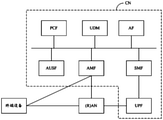
- the core network includes: access and mobility management ( access and mobility management services, AMF) network element, session management function (session management function, SMF) network element, PCF network element, user plane function (user plane function, UPF) network element, application layer function (application function, AF) network element, AUSF network element, and UDM network element.
- the core network may also include some network elements not shown in FIG. 4, such as: security anchor function (security anchor function, SEAF) network element, authentication credential repository and processing function (authentication credential repository and processing function, ARPF), The embodiments of the present application will not be repeated here.
- security anchor function security anchor function, SEAF
- SEAF security anchor function
- ARPF authentication credential repository and processing function
- communication can be classified into different types according to the types of transmitting nodes and receiving nodes.
- the information sent by the network device to the terminal device is called downlink (downlink, DL) communication; the information sent by the terminal device to the network device is called uplink (uplink, UL) communication.
- the network device may specifically refer to a network element in a base station or a core network that can exchange information with the terminal device.
- the communication system may include a network device 101 and one or more terminal devices 102 connected to the network device 101 .
- the network device 101 may specifically be an access network device, for example, the network device 101 may be a device in (R)AN in FIG. 4 .
- One or more terminal devices 102 may be the above-mentioned terminal devices in FIG. 4 .
- the present application provides a communication method, as shown in FIG. 6 , the method includes:
- the sending device sends the first DMRS from the first DMRS port through the first time-frequency resource.
- the sending device when the communication method is applied to uplink communication, the sending device may be the terminal device 102 in FIG. 5 .
- the sending device When the communication method is applied to downlink communication, the sending device may be the network device 101 in FIG. 5 .
- the first time-frequency resource is a part of the time-frequency resource in the second time-frequency resource.
- the second time-frequency resource is the time-frequency resource for mapping the second DMRS of the second DMRS port.
- the first time-frequency resource is part of the second time-frequency resource, which can be understood as the first time-frequency resource is included in the second time-frequency resource and the first time-frequency resource is not completely the same as the second time-frequency resource. Overlapping, that is, at least part of the time-frequency resources in the second time-frequency resources are not included in the first time-frequency resources.
- the system supports that the first DMRS port multiplexes part of the time-frequency resources of the second DMRS port, wherein the sending device can send the first DMRS from the first DMRS port through the first time-frequency resource, and the other sending device or the sending device can send the first DMRS.
- Other devices can send the second DMRS from the second DMRS port through the second time-frequency resource, which is equivalent to multiplexing the first time-frequency resource with the second DMRS port to send the respective DMRS, and then the receiving device
- the second DMRS is obtained by parsing the second time-frequency resource
- the first DMRS is obtained by parsing the first time-frequency resource in the second time-frequency resource.
- the second time-frequency resource occupied by the second DMRS port for sending the second DMRS can be represented as (a) in Figure 2 The REs occupied by CDM group 0 or CDM group 1.
- the second time-frequency resource includes REs whose indices are 0, 2, 4, 6, 8, and 10 in (a) of FIG. 2 .
- the first time-frequency resource may include indexes 0, 2, 4, 6, and 8 , Part of RE in RE of 10.
- the sending device when the sending device or other devices send the second DMRS from the second DMRS port through REs with indexes 0, 2, 4, 6, 8, and 10 in (a) of FIG. 2 , the sending device can use the above-mentioned partial REs
- the first DMRS is sent from the first DMRS port, that is, the above-mentioned part of the REs are multiplexed by the first DMRS port and the second DMRS port at this time.
- the number of subcarriers included in the second time-frequency resource is P times the number of subcarriers included in the first time-frequency resource, where P is an integer greater than 1.
- the first time-frequency resource includes: a set of subcarriers included in the second time-frequency resource that are equally spaced and distributed.
- P-1 subcarriers included in the second time-frequency resource are spaced between two adjacent subcarriers.
- the first time-frequency resource may include REs with indexes 2, 6, and 10. RE.
- REs with indexes 2, 6, and 10 are multiplexed by the first DMRS port and the second DMRS port.
- the second time-frequency resource may include REs with indices of 0, 2, 4, 6, 8, and 10 in the two RBs, that is, the second time-frequency resource
- the frequency resource includes a total of 12 REs.
- the first time-frequency resource may include REs whose indices are 2, 6, and 10 in the two RBs, that is, the first time-frequency resource includes 6 REs in total.
- the orthogonal mask (orthogonal cover code, OCC) of the first DMRS is orthogonal to the OCC corresponding to the first time-frequency resource in the OCC of the second DMRS. That is, the vector inner product of the OCC of the first DMRS and the OCC corresponding to the first time-frequency resource in the OCC of the second DMRS is 0.
- the second time-frequency resource may include indexes 0, 2, 4, 6, 8, 10 REs, that is, the second time-frequency resource includes 12 REs in total.
- the first time-frequency resource may include REs with indexes 2, 6, and 10 of the two REs, that is, the first time-frequency resource includes 6 REs in total, and the OCC of the second DMRS is 6 REs with indexes 2, 6, and 10.
- the vector inner product of the OCC on the RE and the OCC of the first DMRS on the 6 REs with indices 2, 6, and 10 is 0.
- the OCC of the first DMRS and the OCC of the second DMRS in the OCC corresponding to the first time-frequency resource have the same result after cyclic shift.
- the above-mentioned implementation manner can make the OCC of the first DMRS orthogonal to the OCC corresponding to the first time-frequency resource in the OCC of the second DMRS .
- the OCC of the second DMRS is occupied by the index of The OCCs on the REs of 2, 6, and 10 are cyclically shifted to obtain the OCC of the first DMRS.
- the obtained OCC of the first DMRS and the OCC of the second DMRS on the REs with indexes 2, 6, and 10 are orthogonal.
- the receiving device receives the first DMRS from the first DMRS port through the first time-frequency resource, and receives the second DMRS from the second DMRS port through the second time-frequency resource.
- the receiving device when the communication method is applied to uplink communication, the receiving device may be the network device 101 in FIG. 5 .
- the receiving device may be the terminal device 102 in FIG. 5 .
- the second DMRS may be sent by the above-mentioned sending device on the second time-frequency resource through the second DMRS port, and the second DMRS may also be sent by other devices except the sending device through the second DMRS port at the second time-frequency resource. sent on the frequency resource. There is no restriction on this application.
- the first time-frequency resource occupied by the first DMRS transmitted from the first DMRS port is part of the time-frequency resource in the second time-frequency resource, it does not need to be the first DMRS port alone. Allocate additional time-frequency resource overhead.
- the OCC of the first DMRS and the OCC of the second DMRS corresponding to the first time-frequency resource in the OCC are orthogonal, interference between the first DMRS port and the second DMRS port can be avoided.
- the second DMRS port is one of the 8 orthogonal DMRS ports supported by the system under configuration type 1 in the prior art or one of the 12 orthogonal DMRS ports supported by the system under configuration type 2
- the OCC of the first DMRS transmitted through the first DMRS port can be orthogonal to the OCC corresponding to the second DMRS, it will not cause interference to the information transmission of the second DMRS port, so that it can be achieved in the prior art.
- the effect of adding new orthogonal DMRS ports is based on the maximum 8 orthogonal DMRS ports supported by the system under configuration type 1 or the maximum 12 orthogonal DMRS ports supported by the system under configuration type 2.
- the effect of interlayer interference between DMRS ports caused by too many transmission layers between the terminal device and the network device is avoided.
- the sending device sends the first DMRS from the first DMRS port through the first time-frequency resource and the sending device also sends the second DMRS from the second DMRS port through the second time-frequency resource.
- the sending device can be a terminal device (referred to as terminal device 1 ). ), the terminal device 1 sends the first DMRS from the first DMRS port through the first time-frequency resource, and there is another terminal device 2 sends the second DMRS from the second DMRS port through the second time-frequency resource.
- the sending device when the sending device sends the first DMRS from the first DMRS port through the first time-frequency resource, whether there is a device that sends the second DMRS from the second DMRS port through the second time-frequency resource , and whether the device that sends the second DMRS from the second DMRS port through the second time-frequency resource is the above-mentioned sending device or other devices, which may not be limited in this application.
- the sending device sends the second DMRS from the second DMRS port through the second time-frequency resource.
- the uplink communication adopts the CP-OFDM waveform, and the DMRS sequence is generated using the gold sequence. Then the DMRS sequence r(n) satisfies the following formula (1):
- c(i) is a pseudo-random sequence, such as a gold sequence.
- the generation formula of c(i) is:
- N C 1600
- c init satisfies:
- l is the OFDM symbol index, is the number of time slots in a frame, is the number of symbols in a slot.
- ⁇ is the CDM group index.
- n SCID ⁇ ⁇ 0,1 ⁇ is the initialization parameter of the DMRS sequence, is the mask, The value of is determined by different high-level parameter configurations.
- w f (k') corresponds to the frequency domain OCC code of the DMRS
- wt (l') corresponds to the time domain OCC code of the DMRS
- w f (k') wt (l') represents the OCC corresponding to the DMRS on the RE code.
- the values of w f (k'), wt (l') and ⁇ can be determined by predefined configuration information.
- the OCC codes used by the 4 DMRS ports ⁇ 0,1,4,5 ⁇ included in CDM group 0 under configuration type 1 are corresponding to the rows 0, 1, 4, and 5 in the table, respectively.
- w f (k') corresponds to the OCC code in the frequency domain, and the code length is 2;
- wt (l') corresponds to the OCC code in the time domain, and the code length is 2.
- each CDM group occupies two OFDM symbols, which can be understood as frequency domain spreading with OCC code length 2 and time domain spreading with OCC code length 2 in one CDM group
- the combined frequency is equivalent to performing time-frequency domain spreading with OCC of 4.
- the sending device can map the second DMRS to the corresponding RE, so as to send the second DMRS from the second DMRS port through the second time-frequency resource.
- the sending device sends the first DMRS from the first DMRS port through the first time-frequency resource.
- the 4 ports included in the CDM group 0 in the above Table 1 are taken as an example, as shown in FIG. 7 , the CDM group 0 corresponds to 12 REs (frequency domain subcarrier index positions 0, 2, 4, 6, 8, 10, the time domain OFDM symbol indices are 2 and 3).
- the vertical axis in FIG. 7 is the frequency domain position index
- the horizontal axis is the time domain OFDM symbol index.
- the 12 REs can be divided into 3 groups, and each group includes 4 REs (including 2 REs that are adjacent in the frequency domain and 2 REs that are adjacent in the time domain).
- the subcarrier indices of the first group of REs are 0 and 2
- the subcarrier indices of the second group of REs are 4 and 6
- the subcarrier indices of the third group of REs are 8 and 10.
- the OCCs corresponding to the four DMRS ports in each group of REs include ⁇ 1,1,1,1 ⁇ , ⁇ 1,-1,1,-1 ⁇ , ⁇ 1,1,-1,-1 ⁇ , ⁇ 1, -1,-1,1 ⁇ four kinds.
- the OCCs of DMRS port 0 in RE a, RE b, RE c, and RE d are ⁇ 1, 1, 1, 1 ⁇ respectively;
- the OCCs of RE c and RE d are ⁇ 1,-1,1,-1 ⁇ respectively;
- the OCCs of DMRS port 4 at RE a, RE b, RE c, and RE d are ⁇ 1,1,-1,-1 respectively ⁇ ;
- the OCCs of DMRS port 3 at RE a, RE b, RE c, and RE d are ⁇ 1,-1,-1,1 ⁇ respectively, and the same is true for the second group of REs and the third group of REs.
- the REs corresponding to CDM group 0 (taking 1 RB as an example, the RE indices are 0, 2, 4, 6, 8, and 10).
- the OCC of DMRS port 0 and DMRS port 4 is ⁇ 1, 1, 1, 1, 1, 1 ⁇
- the OCC of DMRS port 1 and DMRS port 5 is ⁇ 1, 1, 1, 1, 1, 1 ⁇ .
- the OCC is ⁇ 1,-1,1,-1,1,-1 ⁇ .
- the DMRS adopts configuration type 1, and the second DMRS port is the DMRS port 0 in the above Table 1. Then, in one RB, the second DMRS occupies REs with indexes 0, 2, 4, 6, 8, and 10. Taking FIG. 7 as an example, on the REs whose OFDM symbol index is 2 and RE indexes are 0, 2, 4, 6, 8, and 10 in FIG. 7 , the OCC of the second DMRS is ⁇ 1, 1, 1, 1, 1 ,1 ⁇ . When there are two RBs (ie, 24 consecutive subcarriers), the OCC corresponding to the second DMRS is shown in Table 2 below as ⁇ 1,1,1,1,1,1,1,1,1, 1 ⁇ .
- the REs occupied by the first DMRS are REs whose indexes are 0, 2, 4, 6, 8, and 10 among the REs occupied by the second DMRS whose indexes are 2, 6, and 10. It can be seen from the above that the OCC of the first DMRS at REs with indexes 2, 6, and 10 needs to be orthogonal to the OCC of the second DMRS at REs with indexes 2, 6, and 10.
- the second DMRS in Table 2 is on the 6 REs overlapping with the first DMRS, and the corresponding OCC is:
- the DMRS port 1 in the above Table 1 is on the 6 REs overlapping with the first DMRS, and the corresponding OCC is:
- the OCC of the first DMRS can be expressed by the following formula:
- m represents the relative index of the RE corresponding to the DMRS, which can also be understood as the mth item in the OCC on the RE where the first DMRS and the second DMRS overlap.
- the sending device may send the first DMRS from the first DMRS port through the first time-frequency resource.
- Step 3 The receiving device receives the first DMRS from the first DMRS port through the first time-frequency resource, and receives the second DMRS from the second DMRS port through the second time-frequency resource.
- the receiving device may first demodulate the first DMRS on the first time-frequency resource, so as to perform channel estimation on the first DMRS port according to the first DMRS. Then, after subtracting the interference of the first DMRS, the second DMRS on the second time-frequency resource is demodulated to perform channel estimation on the second DMRS port.
- the demodulation of the first DMRS and the demodulation of the second DMRS by the receiving device can be performed in reverse according to the same principles as the first and second steps above, and the first DMRS can be obtained from the first time-frequency resource.
- DMRS and obtain the second DMRS from the second time-frequency resource There is no restriction on this application.
- the OCC of the first DMRS is equal to the number of subcarriers included in the first time-frequency resource.
- the OCC corresponding to the first time-frequency resource in the OCC of the two DMRSs satisfies the following formula (5):
- s 1 (m) represents the mth item in the OCC of the first DMRS
- s 2 (m) represents the mth item in the OCC corresponding to the first time-frequency resource in the OCC of the second DMRS
- M represents the second The number of RBs corresponding to the second DMRS of the OCC of the first DMRS in the resource block RB of the time-frequency resource is determined by cyclic shift, where M is a multiple of 2
- ⁇ 1 represents the phase shift factor of the first DMRS.
- ⁇ 1 may be any one of 1, 2, 3, 4, and 5.
- Mode 1 When the DMRS is configured as configuration type 1 and the second DMRS port is the DMRS port in Table 1 above, the following formula (6) can be used to map the DMRS sequence r(n) of the first DMRS port to each RE:
- ⁇ represents the phase shift factor of the first DMRS, and 0 ⁇ 3M. That is, it represents the OCC code corresponding to the first DMRS on the RE.
- m 0, the RB in which it is located is the smallest RB (ie, the first RB) among all the M RBs allocated to the transmitting device.
- w f (k'), w t (l'), ⁇ and ⁇ may be determined by predefined configuration information. Exemplarily, Table 1 above can be updated to Table 3 below. The values of w f (k'), w t (l'), ⁇ and ⁇ corresponding to the first DMRS port under configuration type 1 can be determined according to Table 3 below:
- the assigned DMRS ports are DMRS ports 0-7 in the table
- the w f (k'), w t (l') and ⁇ of the DMRS port can be obtained by looking up the table, and then use the above Equation (4) maps the DMRS sequence to each RE.
- the OCC of DMRS ports 0-7 has nothing to do with the phase shift factor ⁇ , that is, ⁇ is not applicable to DMRS ports 0-7. Therefore, ⁇ corresponding to DMRS ports 0-7 in Table 3 is N/A.
- the w f (k'), w t (l'), ⁇ and ⁇ of the DMRS port can be obtained by looking up the table, and then using the above formula (6 ) maps DMRS sequences into REs.
- the value of ⁇ is only 2 or 4 as an example for description. In some scenarios, ⁇ can also take other values, and its value range can be 0 ⁇ 3M positive integer of .
- the OCC of the first DMRS and the OCC of the second DMRS are shown in Table 2 above, and then it can be seen that the OCC of the first DMRS is cyclically shifted with the OCC corresponding to the first time-frequency resource in the OCC of the second DMRS results are the same.
- the OCCs of DMRS port 8 and DMRS port 9 are two orthogonal DMRS ports obtained by cyclically shifting the OCC of DMRS port 0 (the phase shift factor ⁇ is 2 or 4, respectively).
- the OCCs of the DMRS port 12 and the DMRS port 13 are respectively two orthogonal DMRS ports obtained by cyclically shifting the OCC of the DMRS port 0 (the phase shift factor ⁇ is 2 or 4 respectively).
- the OCCs of the DMRS port 10 and the DMRS port 11 are respectively two orthogonal DMRS ports obtained by cyclically shifting the OCC of the DMRS port 2 (the phase shift factor ⁇ is 2 or 4, respectively).
- the above manner 1 can be understood as determining the OCC of the first DMRS by using the phase shift factor ⁇ value corresponding to the first DMRS port in the predefined configuration information (eg, Table 3).
- Mode 2 When the DMRS is configured as configuration type 1 and the second DMRS port is the DMRS port in Table 1 above, the following formula (7) can be used to map the DMRS sequence r(n) of the first DMRS port to each RE:
- m Indicates the first DMRS port Intermediate variable on REs with subcarrier index k and OFDM symbol index 1.
- m ⁇ 6M-1 Indicates the number of subcarriers included in one RB. That is, it represents the OCC code corresponding to the first DMRS on the RE.
- the RB in which it is located is the smallest RB (ie, the first RB) among all the M RBs allocated to the transmitting device.
- the offset position c is used to represent the position of the first time-frequency resource on the second time-frequency resource.
- ⁇ is a constant and 0 ⁇ 3M, for example, ⁇ can take any one of 1, 2, 3, 4, and 5.
- the values of w f (k'), wt (l'), ⁇ and ⁇ may be determined by predefined configuration information. Exemplarily, Table 1 above can be updated to Table 4 below. The values of w f (k'), wt (l'), ⁇ and ⁇ under configuration type 1 can be determined according to the following table 4:
- the OCC of DMRS ports 0-7 has nothing to do with the offset position c and the phase shift factor ⁇ , that is, c and ⁇ are not applicable to DMRS ports 0-7. Therefore, c and ⁇ corresponding to DMRS ports 0-7 in Table 3 are N /A.
- the above manner 2 can be understood as determining the OCC of the first DMRS by using the offset position c corresponding to the first DMRS port in the predefined configuration information (eg, Table 4).
- Mode 3 Similar to Mode 2, when the DMRS is configured as configuration type 1 and the second DMRS port is the DMRS port in Table 1 above, the above formula (7) can be used to convert the DMRS sequence r(n) of the first DMRS port Mapped to each RE. Different from the second mode, the value of ⁇ in the third mode needs to be determined by predefined configuration information. Exemplarily, Table 1 above can be updated to Table 5 below. The values of w f (k'), w t (l'), ⁇ , ⁇ and c under configuration type 1 can be determined according to the following table 5:
- c corresponding to DMRS ports 0-7 in Table 3 is N/A.
- the value of ⁇ is only 2 or 4 as an example for description. In some scenarios, ⁇ can also take other values, and its value range can be 0 ⁇ 3M positive integer of .
- the above method 2 can be understood as determining the first DMRS by the offset position c corresponding to the first DMRS port and the phase shift factor ⁇ value corresponding to the first DMRS port in the predefined configuration information (such as Table 5). the OCC.
- the method provided by the present application further includes:
- the receiving device sends the first indication information, so that the sending device receives the first indication information.
- the first indication information is used to instruct the sending device to send the first DMRS from the first DMRS port through the first time-frequency resource.
- the first indication information is specifically used to indicate at least one of a phase shift factor of the first DMRS or a position of the first time-frequency resource in the second time-frequency resource.
- the first indication information may also be used to indicate the CDM group index of the first DMRS, the frequency domain OCC of the first DMRS (that is, w f (k')), and the time domain OCC of the first DMRS (that is, wt (l') )) and other parameters.
- the sending device is a terminal device and the receiving device is a network device
- the first indication information is sent to the terminal device through the network device, so that the terminal device determines the first DMRS port and uses the first time-frequency resource from the first DMRS port.
- the port sends the first DMRS.
- the first indication information is used to indicate the phase shift factor of the first DMRS.
- the phase shift factor of the first DMRS is used to represent the phase difference between the OCC of the first DMRS and the OCC corresponding to the first time-frequency resource in the OCC of the second DMRS.
- the first indication information may be used to indicate the phase shift factor ⁇ corresponding to the first DMRS. value.
- the transmitting device can use the above formula (6) Map the DMRS sequence r(n) of the first DMRS port to each RE.
- the first indication information is used to indicate the position of the first time-frequency resource in the second time-frequency resource.
- the first indication information may be used to indicate the offset position c corresponding to the first DMRS.
- the transmitting device can use the above formula (7) to map the DMRS sequence r(n) of the first DMRS port to each RE.
- the first indication information is used to indicate the phase shift factor of the first DMRS and the position of the first time-frequency resource in the second time-frequency resource.
- the first indication information can be used to indicate the phase shift factor of the first DMRS and the first The position of the time-frequency resource in the second time-frequency resource.
- the sending device can use the above formula (7) to map the DMRS sequence r(n) of the first DMRS port to each RE.
- the foregoing first indication information includes first information for indicating a port index of the first DMRS port. Furthermore, the method further includes: the sending device determines at least one of a phase shift factor of the first DMRS or a position of the first time-frequency resource in the second time-frequency resource according to the first information in the first indication information.
- the first indication information including the first information is sent to the sending device through the receiving device. Therefore, the sending device can determine the port index of the first DMRS port according to the first information, and then determine the phase shift factor of the first DMRS or the position of the first time-frequency resource in the second time-frequency resource according to the port index of the first DMRS port.
- At least one item, for example, the above-mentioned Table 3 or Table 4 or Table 5 is stored in the transmitting device, and then the transmitting device can determine the phase shift factor or the first DMRS phase shift factor or the first DMRS by looking up the table after determining the first DMRS port index. The position of the time-frequency resource in the second time-frequency resource.
- the sending device can map the DMRS sequence r(n) of the first DMRS port to each RE according to at least one of the phase shift factor of the first DMRS or the position of the first time-frequency resource in the second time-frequency resource , that is, the first DMRS is sent from the first DMRS port through the first time-frequency resource.
- the first indication information is specifically used to indicate at least one of the phase shift factor of the first DMRS or the position of the first time-frequency resource in the second time-frequency resource is achieved.
- the first indication information may be a downlink control indicator (downlink control indicator, DCI). That is, the first DMRS port index may be indicated in the DCI sent by the receiving device to the sending device.
- DCI downlink control indicator
- Example 1 when the rank (rank) of the DMRS port of the sending device is 1, the following table 6 can be used to determine the value of the field representing the first indication information in the DCI:
- the first column represents the value of the field representing the first indication information in the DCI
- the second column represents the number of currently configured CDM groups (number of DMRS CDM group(s) ) without data)
- the third column represents the port index of the DMRS port allocated to the transmitting device
- the fourth column represents the number of pre-DMRS symbols configured by the current system.
- the value 14-21 may be used to indicate the DMRS ports 8-15 in Table 3 or Table 4 or Table 5 above, that is, may be used to indicate the first DMRS port.
- DMRS ports 8-15 When a single table is used to indicate the DMRS ports 8-15 in the above Table 3 or Table 4 or Table 5 (hereinafter referred to as "DMRS ports 8-15"), as shown in Table 7:
- Example 2 when the rank of the DMRS port of the sending device is 2, the following table 8 can be used to determine the value of the field representing the first indication information in the DCI:
- the value 10-15 may be used to indicate that the DMRS port configured for the sending device includes DMRS ports 8-15, that is, the value 10-15 may be used to indicate the first DMRS port.
- Example 3 when the rank of the DMRS port of the sending device is 3, the following table 10 can be used to determine the value of the field representing the first indication information in the DCI:
- value3 and value3 may be used to indicate that the DMRS end configured for the sending device includes DMRS ports 8-15.
- a separate table can be used to transmit indications including DMRS ports 8-15 in the DCI, as shown in Table 12:
- Example 4 when the rank of the DMRS port of the sending device is 4, the following table 13 can be used to determine the value of the field representing the first indication information in the DCI:
- a separate table can be used to transmit indications including DMRS ports 8-15 in the DCI, as shown in Table 14:
- the method provided by the present application further includes:
- the sending device sends the second indication information to the receiving device.
- the second indication information is used to instruct the receiving device to receive the first DMRS from the first DMRS port through the first time-frequency resource.
- the second indication information is specifically used to indicate at least one of a phase shift factor of the first DMRS or a position of the first time-frequency resource in the second time-frequency resource.
- the sending device is a network device and the receiving device is a terminal device
- the second indication information is sent to the terminal device through the network device, so that the terminal device determines the first DMRS port and uses the first time-frequency resource from the first DMRS port.
- the port receives the first DMRS.
- the method further includes:
- the sending device sends the third DMRS from the third DMRS port through the first time-frequency resource.
- the receiving device may receive the third DMRS from the third DMRS port through the first time-frequency resource.
- the orthogonal mask OCC of the third DMRS is orthogonal to the OCC corresponding to the first time-frequency resource in the OCC of the second DMRS.
- s 3 (m) represents the m-th item in the OCC of the third DMRS
- s 2 (m) represents the m-th item in the OCC corresponding to the first time-frequency resource in the OCC of the second DMRS
- the number of RBs corresponding to the second DMRS of the OCC of the first DMRS is determined by cyclic shift, and M is a multiple of 2
- ⁇ 2 represents the phase shift factor of the third DMRS, and ⁇ 1 and ⁇ 2 is different.
- the OCC of the DMRS that is, the second DMRS
- the OCC of another DMRS port that is, the first DMRS port
- a variety of different OCCs can be obtained by using different phase shift factors ⁇ .
- the OCCs of the DMRSs corresponding to these various OCCs can be kept orthogonal to the OCCs of the DMRSs of the original specific DMRS ports.
- a third DMRS that does not cause interference to the first DMRS port and the second DMRS port can be transmitted on the first time-frequency resource multiplexed by the first DMRS port and the second DMRS port.
- the number of orthogonal DMRS ports supported by the system is further increased without increasing the time-frequency resource overhead allocated to the DMRS.
- the method may further include:
- the sending device sends the fourth DMRS from the fourth DMRS port through the third time-frequency resource.
- the third time-frequency resource is included in the second time-frequency resource, and the third time-frequency resource does not overlap with the first time-frequency resource.
- the OCC of the fourth DMRS is orthogonal to the OCC corresponding to the third time-frequency resource in the OCC of the second DMRS.
- the fourth DMRS port may also reuse part of the second time-frequency resources of the second DMRS port other than the first time-frequency resources (that is, the third time-frequency resources) resources), thereby further increasing the number of orthogonal DMRS ports supported by the system.
- the OCC of the fourth DMRS is orthogonal to the OCC corresponding to the third time-frequency resource in the OCC of the second DMRS
- the corresponding description of the OCC orthogonality corresponding to a time-frequency resource will not be repeated here.
- the number of subcarriers included in the second time-frequency resource is P times the number of subcarriers included in the third time-frequency resource, where P is an integer greater than 1.
- the third time-frequency resource includes: a set of subcarriers included in the second time-frequency resource that are equally spaced and distributed. Wherein, P subcarriers included in the second time-frequency resource are spaced between two adjacent subcarriers in the subcarrier set.
- the second DMRS port may be DMRS port 0 in Table 4 above
- the first DMRS may be DMRS port 8 in Table 4 above
- the fourth DMRS may be DMRS port 9 in Table 4 above.
- the OCC of the second DMRS, the OCC of the first DMRS, and the OCC of the fourth DMRS on the two RBs are shown in Table 15 below:
- the fourth DMRS of the fourth DMRS port that does not interfere with the first DMRS port and the second DMRS port is transmitted on the third time-frequency resource other than the first time-frequency resource in the second time-frequency resource.
- the number of orthogonal DMRS ports supported by the system is further increased without increasing the time-frequency resource overhead allocated to the DMRS.
- the receiving device and/or the transmitting device may perform some or all of the steps in the embodiments of the present application. These steps or operations are only examples. In the embodiments of the present application, other operations may also be performed or Variations of various operations. In addition, various steps may be performed in different orders presented in the embodiments of the present application, and may not be required to perform all the operations in the embodiments of the present application.
- the embodiments provided in this application may be related to each other, and may be referred to or referenced to each other.
- the above embodiments mainly introduce the solutions provided by the embodiments of the present application from the perspective of interaction between devices.
- the above-mentioned receiving device or transmitting device includes corresponding hardware structures and/or software modules for executing each function.
- the unit of each example described in conjunction with the embodiments disclosed herein can be implemented in hardware or in the form of a combination of hardware and computer software. Whether a function is performed by hardware or computer software driving hardware depends on the specific application and design constraints of the technical solution. Skilled artisans may implement the described functionality using different methods for each particular application, but such implementations should not be considered beyond the scope of this application.
- a device may be divided into functional modules according to the above method examples.
- each functional module may be divided corresponding to each function, or two or more functions may be integrated into one processing unit. in the module.
- the above-mentioned integrated modules can be implemented in the form of hardware, and can also be implemented in the form of software function modules.
- the division of modules in the embodiment of the present application is schematic, and is only a logical function division, and another division manner may be used in actual implementation.
- FIG. 12 it is a schematic diagram of the composition of a communication apparatus 30 according to an embodiment of the present application.
- the communication apparatus 30 may be a chip or a system-on-chip in the receiving device.
- the communication apparatus 30 can be used to perform the functions of the receiving device designed in the above embodiments.
- the communication device 30 includes:
- the receiving unit 301 is configured to receive the first DMRS from the first demodulation reference signal DMRS port through the first time-frequency resource, and receive the second DMRS from the second DMRS port through the second time-frequency resource.
- the first time-frequency resource is a part of the time-frequency resource in the second time-frequency resource, the orthogonal mask OCC of the first DMRS and the first time-frequency resource in the OCC of the second DMRS
- the OCCs corresponding to the resources are orthogonal.
- the orthogonal mask OCC of the first DMRS is the same as the result of performing cyclic shift on the OCC corresponding to the first time-frequency resource in the OCC of the second DMRS.
- the number of subcarriers included in the second time-frequency resource is P times the number of subcarriers included in the first time-frequency resource; P is an integer greater than 1;
- the first time-frequency resource includes: a set of subcarriers included in the second time-frequency resource that are equally spaced and distributed; wherein, adjacent subcarriers in the set of subcarriers P-1 subcarriers included in the second time-frequency resource are spaced between the two subcarriers.
- s 1 (m) represents the mth item in the OCC of the first DMRS
- s 2 (m) represents the mth item in the OCC corresponding to the first time-frequency resource in the OCC of the second DMRS
- M represents the number of RBs corresponding to the second DMRS for determining the OCC of the first DMRS by cyclic shift in the resource block RB that carries the second time-frequency resource, and M is a multiple of 2
- ⁇ 1 represents the phase shift factor of the first DMRS.
- the receiving unit 301 is further configured to receive a third DMRS from a third DMRS port through the first time-frequency resource; the OCC of the third DMRS and the OCC of the second DMRS are described in The OCC corresponding to the first time-frequency resource satisfies the following formula 2:
- s 3 (m) represents the m-th item in the OCC of the third DMRS
- s 2 (m) represents the m-th item in the OCC corresponding to the first time-frequency resource in the OCC of the second DMRS
- M represents the number of RBs corresponding to the second DMRS for determining the OCC of the first DMRS by cyclic shift in the RB carrying the second time-frequency resource, and M is a multiple of 2
- ⁇ 2 represents the The phase shift factor of the third DMRS, ⁇ 2 is different from ⁇ 1 .
- the receiving unit 301 is further configured to receive a fourth DMRS from a fourth DMRS port through a third time-frequency resource; the third time-frequency resource is included in the second time-frequency resource, and the third time-frequency resource is included in the second time-frequency resource.
- the three time-frequency resources do not overlap with the first time-frequency resource; the orthogonal mask OCC of the fourth DMRS is orthogonal to the OCC corresponding to the third time-frequency resource in the OCC of the second DMRS.
- the number of subcarriers included in the second time-frequency resource is P times the number of subcarriers included in the third time-frequency resource; P is an integer greater than 1;
- the third time-frequency resource includes: a set of subcarriers that are evenly spaced among subcarriers included in the second time-frequency resource; wherein, the interval between two adjacent subcarriers in the subcarrier set is P-1 subcarriers included in the second time-frequency resource.
- the communication apparatus 30 further includes a sending unit 302; the sending unit 302 is configured to send first indication information; the first indication information is used to indicate the first DMRS to a sending device at least one of the phase shift factor of the the phase difference between the OCCs corresponding to the first time-frequency resource in the OCC of the second DMRS; the sending device transmits the first DMRS from the first DMRS port through the first time-frequency resource. equipment;
- the receiving unit 301 is further configured to receive second indication information from a sending device; the second indication information is used to indicate the phase shift factor of the first DMRS or the first indication At least one of the positions of the time-frequency resource in the second time-frequency resource; the phase shift factor of the first DMRS is used to characterize the OCC of the first DMRS and the OCC of the second DMRS.
- the phase difference between the OCCs corresponding to the first time-frequency resource; the sending device is a device that sends the first DMRS from the first DMRS port through the first time-frequency resource.
- FIG. 13 it is a schematic diagram of the composition of another communication apparatus 40 according to an embodiment of the present application.
- the communication device 40 may be a chip or a system-on-chip in the transmitting device.
- the communication apparatus 40 may be used to perform the functions of the sending device involved in the above embodiments.
- the communication device 40 includes:
- a sending unit 401 configured to send a first DMRS from a first demodulation reference signal DMRS port through a first time-frequency resource; wherein the first time-frequency resource is included in a second time-frequency resource, and the second time-frequency resource
- the orthogonal mask OCC of the first DMRS is orthogonal to the OCC corresponding to the first time-frequency resource in the OCC of the second DMRS.
- the orthogonal mask OCC of the first DMRS and the OCC corresponding to the first time-frequency resource in the OCC of the second DMRS have the same result after cyclic shifting.
- the number of subcarriers included in the second time-frequency resource is P times the number of subcarriers included in the first time-frequency resource; P is an integer greater than 1;
- the first time-frequency resource includes: a set of subcarriers included in the second time-frequency resource that are distributed at equal intervals; wherein, adjacent subcarriers in the set of subcarriers P-1 subcarriers included in the second time-frequency resource are spaced between the two subcarriers.
- s 1 (m) represents the mth item in the OCC of the first DMRS
- s 2 (m) represents the mth item in the OCC corresponding to the first time-frequency resource in the OCC of the second DMRS
- M represents the number of RBs corresponding to the second DMRS for determining the OCC of the first DMRS by cyclic shift in the resource block RB that carries the second time-frequency resource, and M is a multiple of 2
- ⁇ 1 represents the phase shift factor of the first DMRS.
- the sending unit 401 is further configured to send a third DMRS from a third DMRS port through the first time-frequency resource; wherein the OCC of the third DMRS and the OCC of the second DMRS are The OCC corresponding to the first time-frequency resource described in the OCC satisfies the following formula 2:
- s 3 (m) represents the m-th item in the OCC of the third DMRS
- s 2 (m) represents the m-th item in the OCC corresponding to the first time-frequency resource in the OCC of the second DMRS
- M represents the number of RBs corresponding to the second DMRS for determining the OCC of the first DMRS by cyclic shift in the resource block RB that carries the second time-frequency resource, and M is a multiple of 2
- ⁇ 2 represents the phase shift factor of the third DMRS, ⁇ 1 and ⁇ 2 are different.
- the sending unit 401 is further configured to send a third DMRS from a third DMRS port through a third time-frequency resource; wherein the third time-frequency resource is included in the second time-frequency resource
- the third time-frequency resource does not overlap with the first time-frequency resource
- the orthogonal mask OCC of the third DMRS is orthogonal to the OCC corresponding to the third time-frequency resource in the OCC of the second DMRS.
- the number of subcarriers included in the second time-frequency resource is P times the number of subcarriers included in the third time-frequency resource; P is an integer greater than 1;
- the third time-frequency resource includes: a set of subcarriers that are evenly spaced among subcarriers included in the second time-frequency resource; wherein, the interval between two adjacent subcarriers in the subcarrier set is P-1 subcarriers included in the second time-frequency resource.
- the communication apparatus further includes a receiving unit 402; the receiving unit 402 is configured to receive first indication information; the first indication information is used to indicate the phase shift factor of the first DMRS or At least one of the positions of the first time-frequency resource in the second time-frequency resource; the phase shift factor of the first DMRS is used to characterize the difference between the OCC of the first DMRS and the second DMRS The phase difference between the OCCs corresponding to the first time-frequency resource in the OCC;
- the sending unit 401 is further configured to send second indication information; the second indication information is used to indicate to the receiving device the phase shift factor of the first DMRS or the first time at least one of the position of the frequency resource in the second time-frequency resource; the phase shift factor of the first DMRS is used to characterize the first DMRS in the OCC and the second DMRS in the OCC.
- a phase difference between OCCs corresponding to a time-frequency resource; the receiving device is a device that receives the first DMRS from the first DMRS port through the first time-frequency resource.
- FIG. 14 shows a schematic diagram of the composition of a communication device 50 .
- the communication device 50 includes: at least one processor 501 and at least one interface circuit 504 .
- the communication device 50 may further include a communication line 502 and a memory 503.
- the processor 501 may be a general-purpose central processing unit (central processing unit, CPU), a microprocessor, an application-specific integrated circuit (ASIC), or one or more processors for controlling the execution of the programs of the present application. integrated circuit.
- CPU central processing unit
- ASIC application-specific integrated circuit
- Communication line 502 may include a path to communicate information between the components described above.
- Interface circuit 504 using any transceiver-like device, for communicating with other devices or communication networks, such as Ethernet, radio access network (RAN), wireless local area networks (WLAN), etc. .
- RAN radio access network
- WLAN wireless local area networks
- Memory 503 may be read-only memory (ROM) or other types of static storage devices that can store static information and instructions, random access memory (RAM), or other types of information and instructions It can also be an electrically erasable programmable read-only memory (EEPROM), a compact disc read-only memory (CD-ROM) or other optical disk storage, CD-ROM storage (including compact discs, laser discs, optical discs, digital versatile discs, Blu-ray discs, etc.), magnetic disk storage media or other magnetic storage devices, or capable of carrying or storing program code in the form of instructions or data structures and capable of being accessed by a computer any other medium, but not limited to.
- the memory may exist independently and be connected to the processor through communication line 502 .
- the memory can also be integrated with the processor.
- the memory 503 is used for storing computer-executed instructions for executing the solution of the present application, and the execution is controlled by the processor 501 .
- the processor 501 is configured to execute the computer-executed instructions stored in the memory 503, thereby implementing the communication method provided by the embodiment of the present application.
- the communication apparatus 50 when the processor 501 executes the instructions stored in the memory 503, the communication apparatus 50 is caused to perform the operations that the receiving device needs to perform as shown in FIG. 6 or FIG. 8-FIG. 10 .
- the communication apparatus 50 when the processor 501 executes the instructions stored in the memory 503, the communication apparatus 50 is caused to perform the operations that the sending device needs to perform as shown in FIG. 6 or FIG. 8-FIG. 10 .
- the computer-executed instructions in the embodiment of the present application may also be referred to as application code, which is not specifically limited in the embodiment of the present application.
- the processor 501 may include one or more CPUs, such as CPU0 and CPU1 in FIG. 14 .
- the apparatus 50 may include multiple processors, such as the processor 501 and the processor 507 in FIG. 14 .
- processors can be a single-core (single-CPU) processor or a multi-core (multi-CPU) processor.
- a processor herein may refer to one or more devices, circuits, and/or processing cores for processing, eg, computer data (computer program instructions).
- the apparatus 50 may further include an output device 505 and an input device 506 .
- the output device 505 is in communication with the processor 501 and can display information in a variety of ways.
- the output device 505 may be a liquid crystal display (LCD), a light emitting diode (LED) display device, a cathode ray tube (CRT) display device, or a projector (projector) Wait.
- Input device 506 is in communication with processor 501 and can receive user input in a variety of ways.
- the input device 506 may be a mouse, a keyboard, a touch screen device or a sensing device, or the like.
- the embodiment of the present application further provides a computer-readable storage medium, where an instruction is stored in the computer-readable storage medium, and when the instruction is executed, the method provided by the embodiment of the present application is executed.
- an instruction is stored in the computer-readable storage medium
- the instruction is executed, the operations that need to be performed by the receiving device as shown in FIG. 6 or FIG. 8 to FIG. 10 are performed.
- the instruction is executed, other operations that need to be performed by the sending device as shown in FIG. 6 or FIG. 8-FIG. 10 are performed.
- Embodiments of the present application also provide a computer program product including instructions.
- the computer can execute the methods provided by the embodiments of the present application.
- the computer program product containing the instructions runs on a computer
- the computer can receive the operations that the device needs to perform as shown in FIG. 6 or FIG. 8-FIG. 10 .
- the computer program product containing the instructions is executed on a computer
- the computer can send other operations that the device needs to perform as shown in FIG. 6 or FIG. 8-FIG. 10 .
- the embodiment of the present application also provides a chip.
- the chip includes a processing circuit and an interface; the processing circuit is used to call and run the computer program stored in the storage medium from the storage medium, so that the chip can execute the method provided by the embodiments of the present application.
- An embodiment of the present application further provides a communication system, including a receiving device and a sending device; wherein: the receiving device is configured to perform the operations performed by the receiving device in the foregoing embodiments, for example, as shown in FIG. 6 or FIG. 8 to FIG. 10 .
- the shown operations need to be performed by the receiving device; the sending device is used to perform the operations performed by the sending device in the above embodiments, for example, the operations that the sending device needs to perform as shown in FIG. 6 or FIG. 8-FIG. 10 .
- the functions or actions or operations or steps in the above embodiments may be implemented in whole or in part by software, hardware, firmware or any combination thereof.
- a software program When implemented using a software program, it may be implemented in whole or in part in the form of a computer program product.
- the computer program product includes one or more computer instructions. When the computer program instructions are loaded and executed on the computer, all or part of the processes or functions described in the embodiments of the present application are generated.
- the computer may be a general purpose computer, special purpose computer, computer network, or other programmable device.
- the computer instructions may be stored in or transmitted from one computer-readable storage medium to another computer-readable storage medium, for example, the computer instructions may be downloaded from a website site, computer, server, or data center Transmission to another website site, computer, server, or data center by wire (eg, coaxial cable, optical fiber, digital subscriber line, DSL) or wireless (eg, infrared, wireless, microwave, etc.).
- the computer-readable storage medium can be any available medium that can be accessed by a computer or data storage devices including one or more servers, data centers, etc. that can be integrated with the medium.
- the usable media may be magnetic media (eg, floppy disks, hard disks, magnetic tapes), optical media (eg, DVDs), or semiconductor media (eg, solid state disks (SSDs)), and the like.
Landscapes
- Engineering & Computer Science (AREA)
- Signal Processing (AREA)
- Computer Networks & Wireless Communication (AREA)
- Mobile Radio Communication Systems (AREA)
Abstract
本申请提供一种通信方法及装置,涉及通信技术领域。本申请用于减小因终端设备与网络设备之间的传输层数过多而导致DMRS端口之间的层间干扰。该方法包括:接收设备通过第一时频资源从第一解调参考信号DMRS端口接收第一DMRS,通过第二时频资源从第二DMRS端口接收第二DMRS;其中,所述第一时频资源是所述第二时频资源中的部分时频资源,所述第一DMRS的正交掩码OCC与所述第二DMRS的OCC中所述第一时频资源对应的OCC正交。
Description
本申请实施例涉及通信技术领域,尤其涉及一种通信方法及装置。
在现有移动通信系统中,系统支持的正交解调参考信号(demodulation reference signal,DMRS)端口的最大复用层数是受到限制的。以新空口(New RAT,NR)无线接入技术为例,当上行或下行通信采用基于循环前缀的正交频分复用(cyclic prefixed orthogonal frequency division multiplexing,CP-OFDM)波形时,CP-OFDM波形可以支持两种DMRS配置,即配置类型1(configuration type 1)和配置类型2(configuration type 2)。在配置类型1(configuration type 1)下,系统最大支持8层正交DMRS端口复用;在配置类型2(configuration type 2)下,系统最大支持12层正交DMRS端口复用。另外,上行还支持采用离散傅利叶变换扩展的正交频分复用(discrete fourier transform-spread-orthogonal frequency division multiplexing,DFT-S-OFDM)波形,默认采用DMRS配置类型1,系统最大支持8层正交DMRS端口复用。
另一方面,随着移动通信的发展以及新兴业务的出现,对高速率的需求越来越大。增加多用户配对的传输层数有利于提升系统吞吐量。但随着传输层数的增加,正交的DMRS端口可能会出现不够用的情况。当网络设备在对终端设备进行多用户配对时,如果实际配对的总层数超出系统支持的正交DMRS端口时,DMRS端口之间就会引入层间干扰。
因此,如何避免因终端设备与网络设备之间的传输层数过多而导致DMRS端口之间的层间干扰,这是目前需要解决的问题。
发明内容
本申请实施例提供一种通信方法及装置,用于减少因终端设备与网络设备之间的传输层数过多而导致DMRS端口之间的层间干扰。为了达到以上目的,本申请实施例提供以下技术方案:
第一方面,提供一种通信方法,该方法包括接收设备通过第一时频资源从第一解调参考信号DMRS端口接收第一DMRS,通过第二时频资源从第二DMRS端口接收第二DMRS;其中,所述第一时频资源是所述第二时频资源中的部分时频资源,所述第一DMRS的正交掩码OCC与所述第二DMRS的OCC中所述第一时频资源对应的OCC正交。
在本申请上述方法中,首先由于从第一DMRS端口进行传输的第一DMRS所占用的第一时频资源是第二时频资源中的部分时频资源,因此不需要单独为第一DMRS端口分配额外的时频资源开销。另外,由于第一DMRS的OCC与第二DMRS的OCC中第一时频资源对应的OCC是正交的,因此可以避免第一DMRS端口与第二DMRS端口之间的干扰。进一步的,当第二DMRS端口为现有技术中configuration type 1下 系统最大支持的8个正交DMRS端口中的一个或者configuration type 2下系统最大支持的12个正交DMRS端口中的一个的情况下,由于本申请中通过第一DMRS端口传输的第一DMRS的OCC能够与第二DMRS对应的OCC正交,因此不会对第二DMRS端口的信息传输产生干扰,从而可以达到在现有技术中configuration type 1下系统最大支持的8个正交DMRS端口或configuration type 2下系统最大支持的12个正交DMRS端口的基础上,增加新的正交DMRS端口的效果。从而避免因终端设备与网络设备之间的传输层数过多而导致DMRS端口之间的层间干扰的效果。
在一种实现方式中,所述第一DMRS的正交掩码OCC,与所述第二DMRS的OCC中所述第一时频资源对应的OCC进行循环移位后的结果相同。
通过上述实现方式可以实现使第一DMRS的OCC与第二DMRS的OCC中第一时频资源对应的OCC正交。
在一种实现方式中,所述第二时频资源所包含子载波个数是所述第一时频资源所包含子载波的个数的P倍;P为大于1的整数;在时域的一个正交频分复用OFDM符号上,所述第一时频资源包括:所述第二时频资源所包含的子载波中等间隔分布的子载波集合;其中,所述子载波集合中相邻两个子载波之间间隔P-1个所述第二时频资源所包含的子载波。
通过上述实现方式,由于第一时频资源包括第二时频资源所包含的子载波中等间隔分布的子载波集合,因此便于确定出符合条件(即与第二DMRS在第一时频资源对应的OCC正交)的第一DMRS的OCC。
在一种实现方式中,P=2;所述第一DMRS的OCC与所述第二DMRS的OCC中所述第一时频资源对应的OCC,满足以下公式一:
其中,s
1(m)表示所述第一DMRS的OCC中的第m项,s
2(m)表示所述第二DMRS的OCC中所述第一时频资源对应的OCC中的第m项;M表示承载所述第二时频资源的资源块RB中用于通过循环移位确定所述第一DMRS的OCC的第二DMRS所对应的RB的个数,M为2的倍数;ω
1表示所述第一DMRS的相移因子。
通过上述实现方式,可以利用上述公式一确定第一DMRS的OCC,从而实现方便快捷的确定出第一DMRS的OCC。
在一种实现方式中,该方法还包括:所述接收设备通过所述第一时频资源从第三DMRS端口接收第三DMRS。所述第三DMRS的OCC与所述第二DMRS的OCC中所述第一时频资源对应的OCC,满足以下公式二:
其中,s
3(m)表示所述第三DMRS的OCC中的第m项,s
2(m)表示所述第二DMRS的OCC中所述第一时频资源对应的OCC中的第m项;M表示承载所述第二时频资源的RB中用于通过循环移位确定所述第一DMRS的OCC的第二DMRS所对应的RB的个数,M为2的倍数;ω
2表示所述第三DMRS的相移因子,ω
2与ω
1不同。
通过上述实现方式,考虑到当采用通过对特定DMRS端口(即第二DMRS端口)的DMRS(即第二DMRS)的OCC进行循环移位,来得到另一DMRS端口(即第一 DMRS端口)的DMRS(即第一DMRS)的OCC的情况下,可以通过采用不同相移因子ω,得到多种不同的OCC。这些多种不同的OCC所对应的DMRS的OCC,都可以与原特定DMRS端口的DMRS的OCC保持正交。因此,通过上述实现方式可以在第一DMRS端口以及第二DMRS端口复用的第一时频资源上,传输不对第一DMRS端口和第二DMRS端口产生干扰的第三DMRS。从而达到不增加分配给DMRS的时频资源开销的情况下,进一步增加系统所支持的正交DMRS端口的数量。
在一种实现方式中,该方法还包括:所述接收设备通过第三时频资源从第四DMRS端口接收第四DMRS;所述第三时频资源包含于所述第二时频资源,所述第三时频资源与所述第一时频资源不重叠;所述第四DMRS的正交掩码OCC与第二DMRS的OCC中所述第三时频资源对应的OCC正交。
通过上述实现方式,可以由第四DMRS端口复用第二DMRS端口的第二时频资源中除第一时频资源之外的部分时频资源(即第三时频资源),从而进一步增加系统支持的正交DMRS端口的个数。
在一种实现方式中,所述第二时频资源所包含子载波个数是所述第三时频资源所包含子载波的个数的P倍;P为大于1的整数;在时域的一个OFDM符号上,所述第三时频资源包括:所述第二时频资源所包含的子载波中等间隔分布的子载波集合;其中,所述子载波集合中相邻两个子载波之间间隔P-1个所述第二时频资源所包含的子载波。
通过上述实现方式,由于第三时频资源包括第二时频资源所包含的子载波中等间隔分布的子载波集合,因此便于确定出符合条件(即与第二DMRS在第三时频资源对应的OCC正交)的第四DMRS的OCC。
在一种实现方式中,该方法还包括:所述接收设备发送第一指示信息;所述第一指示信息,用于向发送设备指示所述第一DMRS的相移因子或所述第一时频资源在所述第二时频资源中的位置中至少一项;所述第一DMRS的相移因子,用于表征所述第一DMRS的OCC与所述第二DMRS的OCC中所述第一时频资源对应的OCC之间的相位差;所述发送设备为通过所述第一时频资源从所述第一DMRS端口发送所述第一DMRS的设备;
通过上述实现方式,发送设备可以根据第一指示信息确定第一DMRS的相移因子或所述第一时频资源在所述第二时频资源中的位置,以便通过第一时频资源从第一DMRS端口发送第一DMRS。也可以理解为,上述实现方式可以通过接收设备发送第一指示信息的方式,为发送设备配置第一DMRS端口。
在一种实现方式中,所述方法还包括:所述接收设备接收来自发送设备的第二指示信息;所述第二指示信息,用于指示所述第一DMRS的相移因子或所述第一时频资源在所述第二时频资源中的位置中至少一项;所述第一DMRS的相移因子,用于表征所述第一DMRS的OCC与所述第二DMRS的OCC中所述第一时频资源对应的OCC之间的相位差;所述发送设备为通过所述第一时频资源从所述第一DMRS端口发送所述第一DMRS的设备。
通过上述实现方式,接收设备可以根据第一指示信息确定第一DMRS的相移因子或所述第一时频资源在所述第二时频资源中的位置,以便通过第一时频资源从第一 DMRS端口接收第一DMRS。也就是说,可以通过接收设备接收第一指示信息的方式,使接收设备获知发送设备准备通过第一时频资源从第一DMRS端口发送第一DMRS。
第二方面,提供一种通信方法,该方法包括:发送设备通过第一时频资源从第一解调参考信号DMRS端口发送第一DMRS;其中,所述第一时频资源包含于第二时频资源,所述第二时频资源为用于映射所述第二DMRS端口的第二DMRS的时频资源,所述第一DMRS的正交掩码OCC与第二DMRS的OCC中所述第一时频资源对应的OCC正交。
在一种实现方式中,所述第一DMRS的正交掩码OCC与第二DMRS的OCC中所述第一时频资源对应的OCC进行循环移位后的结果相同。
在一种实现方式中,所述第二时频资源所包含子载波个数是所述第一时频资源所包含子载波的个数的P倍;P为大于1的整数;在时域的一个正交频分复用OFDM符号上,所述第一时频资源包括:所述第二时频资源所包含的子载波中等间隔分布的子载波集合;其中,所述子载波集合中相邻两个子载波之间间隔P-1个所述第二时频资源所包含的子载波。
在一种实现方式中,P=2;所述第一DMRS的OCC与所述第二DMRS的OCC中所述第一时频资源对应的OCC,满足以下公式一:
其中,s
1(m)表示所述第一DMRS的OCC中的第m项,s
2(m)表示所述第二DMRS的OCC中所述第一时频资源对应的OCC中的第m项;M表示承载所述第二时频资源的资源块RB中用于通过循环移位确定所述第一DMRS的OCC的第二DMRS所对应的RB的个数,M为2的倍数;ω
1表示所述第一DMRS的相移因子。
在一种实现方式中,该方法还包括:所述发送设备通过所述第一时频资源从第三DMRS端口发送第三DMRS;其中,所述第三DMRS的OCC与所述第二DMRS的OCC中所述第一时频资源对应的OCC,满足以下公式二:
其中,s
3(m)表示所述第三DMRS的OCC中的第m项,s
2(m)表示所述第二DMRS的OCC中所述第一时频资源对应的OCC中的第m项;M表示承载所述第二时频资源的资源块RB中用于通过循环移位确定所述第一DMRS的OCC的第二DMRS所对应的RB的个数,M为2的倍数;ω
2表示所述第三DMRS的相移因子,ω
1与ω
2不同。
在一种实现方式中,该方法还包括:所述发送设备通过第三时频资源从第三DMRS端口发送第三DMRS;其中,所述第三时频资源包含于所述第二时频资源并且所述第三时频资源与所述第一时频资源不重叠,所述第三DMRS的正交掩码OCC与第二DMRS的OCC中所述第三时频资源对应的OCC正交。
在一种实现方式中,所述第二时频资源所包含子载波个数是所述第三时频资源所包含子载波的个数的P倍;P为大于1的整数;在时域的一个OFDM符号上,所述第三时频资源包括:所述第二时频资源所包含的子载波中等间隔分布的子载波集合;其中,所述子载波集合中相邻两个子载波之间间隔P-1个所述第二时频资源所包含的子载波。
在一种实现方式中,该方法还包括:所述发送设备接收第一指示信息;所述第一指示信息,用于指示所述第一DMRS的相移因子或所述第一时频资源在所述第二时频资源中的位置中至少一项;所述第一DMRS的相移因子,用于表征所述第一DMRS的OCC与所述第二DMRS的OCC中所述第一时频资源对应的OCC之间的相位差;
在一种实现方式中,该方法还包括:所述发送设备发送第二指示信息;所述第二指示信息,用于向接收设备指示所述第一DMRS的相移因子或所述第一时频资源在所述第二时频资源中的位置中至少一项;所述第一DMRS的相移因子,用于表征所述第一DMRS的OCC与所述第二DMRS的OCC中所述第一时频资源对应的OCC之间的相位差;所述接收设备为通过所述第一时频资源从所述第一DMRS端口接收所述第一DMRS的设备。
第三方面,提供一种通信装置,该通信装置包括:接收单元,用于通过第一时频资源从第一解调参考信号DMRS端口接收第一DMRS,通过第二时频资源从第二DMRS端口接收第二DMRS;其中,所述第一时频资源是所述第二时频资源中的部分时频资源,所述第一DMRS的正交掩码OCC与所述第二DMRS的OCC中所述第一时频资源对应的OCC正交。
在一种实现方式中,所述第一DMRS的正交掩码OCC,与所述第二DMRS的OCC中所述第一时频资源对应的OCC进行循环移位后的结果相同。
在一种实现方式中,所述第二时频资源所包含子载波个数是所述第一时频资源所包含子载波的个数的P倍;P为大于1的整数;在时域的一个正交频分复用OFDM符号上,所述第一时频资源包括:所述第二时频资源所包含的子载波中等间隔分布的子载波集合;其中,所述子载波集合中相邻两个子载波之间间隔P-1个所述第二时频资源所包含的子载波。
在一种实现方式中,P=2;所述第一DMRS的OCC与所述第二DMRS的OCC中所述第一时频资源对应的OCC,满足以下公式一:
其中,s
1(m)表示所述第一DMRS的OCC中的第m项,s
2(m)表示所述第二DMRS的OCC中所述第一时频资源对应的OCC中的第m项;M表示承载所述第二时频资源的资源块RB中用于通过循环移位确定所述第一DMRS的OCC的第二DMRS所对应的RB的个数,M为2的倍数;ω
1表示所述第一DMRS的相移因子。
在一种实现方式中,接收单元,还用于通过所述第一时频资源从第三DMRS端口接收第三DMRS;所述第三DMRS的OCC与所述第二DMRS的OCC中所述第一时频资源对应的OCC,满足以下公式二:
其中,s
3(m)表示所述第三DMRS的OCC中的第m项,s
2(m)表示所述第二DMRS的OCC中所述第一时频资源对应的OCC中的第m项;M表示承载所述第二时频资源的RB中用于通过循环移位确定所述第一DMRS的OCC的第二DMRS所对应的RB的个数,M为2的倍数;ω
2表示所述第三DMRS的相移因子,ω
2与ω
1不同。
在一种实现方式中,接收单元,还用于通过第三时频资源从第四DMRS端口接收 第四DMRS;所述第三时频资源包含于所述第二时频资源,所述第三时频资源与所述第一时频资源不重叠;所述第四DMRS的正交掩码OCC与第二DMRS的OCC中所述第三时频资源对应的OCC正交。
在一种实现方式中,所述第二时频资源所包含子载波个数是所述第三时频资源所包含子载波的个数的P倍;P为大于1的整数;在时域的一个OFDM符号上,所述第三时频资源包括:所述第二时频资源所包含的子载波中等间隔分布的子载波集合;其中,所述子载波集合中相邻两个子载波之间间隔P-1个所述第二时频资源所包含的子载波。
在一种实现方式中,所述通信装置还包括发送单元;所述发送单元,用于发送第一指示信息;所述第一指示信息,用于向发送设备指示所述第一DMRS的相移因子或所述第一时频资源在所述第二时频资源中的位置中至少一项;所述第一DMRS的相移因子,用于表征所述第一DMRS的OCC与所述第二DMRS的OCC中所述第一时频资源对应的OCC之间的相位差;所述发送设备为通过所述第一时频资源从所述第一DMRS端口发送所述第一DMRS的设备;
在一种实现方式中,所述接收单元,还用于接收来自发送设备的第二指示信息;所述第二指示信息,用于指示所述第一DMRS的相移因子或所述第一时频资源在所述第二时频资源中的位置中至少一项;所述第一DMRS的相移因子,用于表征所述第一DMRS的OCC与所述第二DMRS的OCC中所述第一时频资源对应的OCC之间的相位差;所述发送设备为通过所述第一时频资源从所述第一DMRS端口发送所述第一DMRS的设备。
第四方面,提供一种通信装置,该通信装置包括:发送单元,用于通过第一时频资源从第一解调参考信号DMRS端口发送第一DMRS;其中,所述第一时频资源包含于第二时频资源,所述第二时频资源为用于映射所述第二DMRS端口的第二DMRS的时频资源,所述第一DMRS的正交掩码OCC与第二DMRS的OCC中所述第一时频资源对应的OCC正交。
在一种实现方式中,所述第一DMRS的正交掩码OCC与第二DMRS的OCC中所述第一时频资源对应的OCC进行循环移位后的结果相同。
在一种实现方式中,所述第二时频资源所包含子载波个数是所述第一时频资源所包含子载波的个数的P倍;P为大于1的整数;在时域的一个正交频分复用OFDM符号上,所述第一时频资源包括:所述第二时频资源所包含的子载波中等间隔分布的子载波集合;其中,所述子载波集合中相邻两个子载波之间间隔P-1个所述第二时频资源所包含的子载波。
在一种实现方式中,P=2;所述第一DMRS的OCC与所述第二DMRS的OCC中所述第一时频资源对应的OCC,满足以下公式一:
其中,s
1(m)表示所述第一DMRS的OCC中的第m项,s
2(m)表示所述第二DMRS的OCC中所述第一时频资源对应的OCC中的第m项;M表示承载所述第二时频资源的资源块RB中用于通过循环移位确定所述第一DMRS的OCC的第二DMRS所对应的RB的个数,M为2的倍数;ω
1表示所述第一DMRS的相移因子。
在一种实现方式中,所述发送单元,还用于通过所述第一时频资源从第三DMRS端口发送第三DMRS;其中,所述第三DMRS的OCC与所述第二DMRS的OCC中所述第一时频资源对应的OCC,满足以下公式二:
其中,s
3(m)表示所述第三DMRS的OCC中的第m项,s
2(m)表示所述第二DMRS的OCC中所述第一时频资源对应的OCC中的第m项;M表示承载所述第二时频资源的资源块RB中用于通过循环移位确定所述第一DMRS的OCC的第二DMRS所对应的RB的个数,M为2的倍数;ω
2表示所述第三DMRS的相移因子,ω
1与ω
2不同。
在一种实现方式中,所述发送单元,还用于通过第三时频资源从第三DMRS端口发送第三DMRS;其中,所述第三时频资源包含于所述第二时频资源并且所述第三时频资源与所述第一时频资源不重叠,所述第三DMRS的正交掩码OCC与第二DMRS的OCC中所述第三时频资源对应的OCC正交。
在一种实现方式中,所述第二时频资源所包含子载波个数是所述第三时频资源所包含子载波的个数的P倍;P为大于1的整数;在时域的一个OFDM符号上,所述第三时频资源包括:所述第二时频资源所包含的子载波中等间隔分布的子载波集合;其中,所述子载波集合中相邻两个子载波之间间隔P-1个所述第二时频资源所包含的子载波。
在一种实现方式中,该通信装置还包括接收单元;所述接收单元,用于接收第一指示信息;所述第一指示信息,用于指示所述第一DMRS的相移因子或所述第一时频资源在所述第二时频资源中的位置中至少一项;所述第一DMRS的相移因子,用于表征所述第一DMRS的OCC与所述第二DMRS的OCC中所述第一时频资源对应的OCC之间的相位差;
在一种实现方式中,所述发送单元,还用于发送第二指示信息;所述第二指示信息,用于向接收设备指示所述第一DMRS的相移因子或所述第一时频资源在所述第二时频资源中的位置中至少一项;所述第一DMRS的相移因子,用于表征所述第一DMRS的OCC与所述第二DMRS的OCC中所述第一时频资源对应的OCC之间的相位差;所述接收设备为通过所述第一时频资源从所述第一DMRS端口接收所述第一DMRS的设备。
第五方面,提供一种通信装置,该通信装置包括至少一个处理器和接口电路,所述至少一个处理器用于通过所述接口电路与其它装置通信,以执行如上述第一方面所提供的通信方法。
第六方面,提供一种通信装置,该通信装置包括至少一个处理器和接口电路,所述至少一个处理器用于通过所述接口电路与其它装置通信,以执行如上述第二方面所提供的通信方法。
第七方面,提供一种芯片,该芯片包括处理电路和接口;所述处理电路用于从存储介质中调用并运行所述存储介质中存储的计算机程序,以执行如上述第一方面所提供的通信方法,或者,执行如上述第二方面所提供的通信方法。
第八方面,提供一种计算机可读存储介质,该计算机可读存储介质中存储有指令;当所述指令运行时,以执行如上述第一方面所提供的通信方法,或者,执行如上述第 二方面所提供的通信方法。
第九方面,提供一种计算机程序产品,包括指令;当所述指令在计算机上运行时,使得计算机执行如上述第一方面所提供的通信方法,或者,执行如上述第二方面所提供的通信方法。
第十方面,提供一种通信系统,包括:包括接收设备和发送设备;其中:所述接收设备,用于执行如上述第一方面所提供的通信方法;所述发送设备,用于执行如上述第二方面所提供的通信方法。
上述第二方面至第十方面中任一种技术方案所带来的技术效果可以参见上述第一方面所提供技术方案所带来的技术效果,此处不再赘述。
图1为现有技术提供的一种导频图的示意图之一;
图2为现有技术提供的一种导频图的示意图之二;
图3为现有技术提供的一种导频图的示意图之三;
图4为本申请实施例提供的一种网络架构示意图之一;
图5为本申请实施例提供的一种网络架构示意图之二;
图6为本申请实施例提供的一种通信方法的流程示意图之一;
图7为本申请实施例提供的一种导频图的示意图;
图8为本申请实施例提供的一种通信方法的流程示意图之二;
图9为本申请实施例提供的一种通信方法的流程示意图之三;
图10为本申请实施例提供的一种通信方法的流程示意图之四;
图11为本申请实施例提供的一种通信方法的流程示意图之五;
图12为本申请实施例提供的一种通信装置的结构示意图之一;
图13为本申请实施例提供的一种通信装置的结构示意图之二;
图14为本申请实施例提供的一种通信装置的结构示意图之三。
下面将结合本申请实施例中的附图,对本申请实施例中的技术方案进行描述。其中,为了便于清楚描述本申请实施例的技术方案,在本申请的实施例中,采用了“第一”、“第二”等字样对功能和作用基本相同的相同项或相似项进行区分。本领域技术人员可以理解“第一”、“第二”等字样并不对数量和执行次序进行限定,并且“第一”、“第二”等字样也并不限定一定不同。同时,在本申请实施例中,“示例性的”或者“例如”等词用于表示作例子、例证或说明。本申请实施例中被描述为“示例性的”或者“例如”的任何实施例或设计方案不应被解释为比其它实施例或设计方案更优选或更具优势。确切而言,使用“示例性的”或者“例如”等词旨在以具体方式呈现相关概念,便于理解。
本申请实施例描述的网络架构以及业务场景是为了更加清楚的说明本申请实施例的技术方案,并不构成对于本申请实施例提供的技术方案的限定,本领域普通技术人员可知,随着网络架构的演变和新业务场景的出现,本申请实施例提供的技术方案对于类似的技术问题,同样适用。
以下对本申请实施例所涉及的相关技术进行介绍:
1、资源块(resource BLOCK,RB)
在无线资源中,在时域上最小的资源粒度可以是一个正交频分复用(Orthogonal Frequency Division Multiplexing,OFDM)符号(symbol),可简称为符号(symbol);在频域上,最小的资源粒度可以是一个子载波。一个OFDM符号和一个子载波组成一个资源元素(resource element,RE)。物理层在进行资源映射的时候,是以RE为基本单位的。在一些通信协议中,例如在长期演进(long term evolution,LTE)标准协议中,一个时隙(slot)内所有的OFDM符号与频域上12个子载波组成一个RB,如图1所示。其中,一个时隙的OFDM符号个数可以为6个,也可以为7个。在另一些通信协议中,例如在新空口(New RAT,NR)标准协议中,1个RB包括一个OFDM符号以及12个子载波。
2、解调参考信号(demodulation reference signal,DMRS)端口
在移动通信网络中,发送设备(例如终端设备)可以通过一个或多个天线端口向接收设备(例如基站)发送无线信号。其中,天线端口作为一个逻辑上的概念,可以对应一个物理发射天线,也可以对应多个物理发射天线,这两种情况下接收设备的接收机(receiver)都不会去分解来自同一个天线端口的信号。因为从接收设备的角度来看,不管信道是由单个物理发射天线形成的,还是由多个物理发射天线合并而成的,这个天线端口对应的参考信号(reference signal)定义了这个天线端口。其中,对应DMRS的天线端口可以被称为DMRS端口,接收设备可以根据DMRS估计得到这个天线端口的信道信息。当接收设备为基站时,基站便可以根据信道估计结果进行物理上行共享信道(physical uplink shared channel,PUSCH)数据解调。当接收设备为终端设备时,终端设备便可以根据信道估计结果进行物理下行共享信道(physical downlink shared channel,PDSCH)数据解调。
目前在移动通信网络中,可以通过使多层DMRS端口的DMRS正交,来实现通过多层DMRS端口同时向接收设备发送信息。具体的,在进行上行DMRS信道估计中,系统最大支持的DMRS正交的DMRS端口的个数,与当前采用的波形、DMRS配置类型相关。
例如,在新无线接入技术(new radio access technology,NR)系统中,上行通信可以支持两种波形:基于循环前缀的正交频分复用(cyclic prefixed orthogonal frequency division multiplexing,CP-OFDM),或者基于离散傅利叶变换扩展的正交频分复用(discrete fourier transform-spread-orthogonal frequency division multiplexing,DFT-S-OFDM)波形。其中,通过高层信令配置,可以确定上行通信具体采用哪种波形。
其中,上行通信所采用波形不同,会导致DMRS序列的生成方式不同。例如,在NR系统中,DFT-S-OFDM波形对应DMRS采用ZC序列,而CP-OFDM波形对应DMRS采用gold序列。对于CP-OFDM波形而言,可以支持两种DMRS配置,即配置类型1(configuration type 1)和配置类型2(configuration type 2)。在配置类型1(configuration type 1)下,系统支持8端口DMRS正交,即最大支持8层正交DMRS端口复用;在配置类型2(configuration type 2)下,系统支持12端口DMRS正交,即系统最大支 持12层正交DMRS端口复用。
另外,根据DMRS时域位置的不同,可将DMRS分为前置的DMRS(front-loaded DMRS)和额外的DMRS(additional DMRS)。其中,front-loaded DMRS放在一个时隙内的前几个符号,并且最多可配置两个符号。
在多层正交DMRS端口复用的情况下,在频域上,不同的DMRS端口被划分成不同的码分复用(code division multiplexing,CDM)组(group)。其中,同一个CDM group内的DMRS端口利用正交掩码(orthogonal cover code,OCC)来进行时频域上的扩展,并能够保证不同DMRS端口上的正交性,从而提高信道估计的准确性。
例如,图2所示为一种采用configuration type 1的DMRS的导频图案的示意图。其中,当为DMRS配置一个符号时,图2中的(a)中两种图案的RE分别表示CDM group 0和CDM group 1所占RE,p0,p1,p2,p3分别表示DMRS端口索引。其中,在同一个CDM group内,频域采用频域OCC来保证同一CDM group内的两个DMRS端口的DMRS序列正交。可以看出,当采用configuration type 1并且DMRS配置一个符号时,系统最大支持4层正交DMRS端口复用。
当为DMRS配置两个符号时,图2中的(b)中两种图案的RE分别表示CDM group 0和CDM group 1所占RE,p0,p1,...,p6,p7分别表示DMRS端口索引。其中,在同一个CDM group内,通过频域OCC(码长为2)以及时域OCC(码长为2)来保证同一CDM group内的4个DMRS端口的DMRS序列正交。可以看出,当采用configuration type 1并且DMRS配置二个符号时,系统最大支持8层正交DMRS端口复用。
再例如,图3所示为一种采用configuration type 2的DMRS的导频图案的示意图。其中,当为DNRS配置一个符号时,图3中的(a)中三种图案的RE分别表示CDM group 0、CDM group 1以及CDM group 2所占RE,p0,p1,...p4,p5分别表示DMRS端口索引。其中,在同一个CDM group内,频域采用频域OCC来保证同一CDM group内的两个DMRS端口的DMRS序列正交。可以看出,当采用configuration type 2并且DMRS配置一个符号时,系统最大支持6层正交DMRS端口复用。
当为DMRS配置两个符号时,图3中的(b)中三种图案的RE分布表示CDM group 0、CDM group 1以及CDM group 2所占RE,p0,p1,...p10,p11分布表示DMRS端口索引。其中,在同一个CDM group内,频域采用或频域OCC来保证同一CDM group内的四个DMRS端口的DMRS序列正交。可以看出,当采用configuration type 2并且DMRS配置二个符号时,系统最大支持12层正交DMRS端口复用。
以下结合示例,对本申请实施例所提供的技术方案进行介绍。本申请实施例所提供技术方案可应用于各类通信系统,例如采用NR技术、长期演进(long term evolution,LTE)技术或其他无线接入技术的通信系统。
示例性的,图4为应用本申请实施例所提供技术方案的一种网络架构的示意图。其中,该网络中可以包括:终端设备、无线接入通信网络(radio access network,RAN)或者接入通信网络(access network,AN)(RAN和AN统称为(R)AN),以及核心网(core network,CN)。
其中,终端设备可以是一种具有无线收发功能的设备。该终端设备可以有不同的名称,例如用户设备(user equipment,UE)、接入设备、终端单元、终端站、移动 站、移动台、远方站、远程终端、移动设备、无线通信设备、终端代理或终端装置等。终端设备可以被部署在陆地上,包括室内或室外、手持或车载;也可以被部署在水面上(如轮船等);还可以被部署在空中(例如飞机、气球和卫星上等)。终端设备包括具有无线通信功能的手持式设备、车载设备、可穿戴设备或者计算设备。例如,终端设备可以是手机(mobile phone)、平板电脑或带无线收发功能的电脑。终端设备还可以是虚拟现实(virtual reality,VR)设备、增强现实(augmented reality,AR)设备、工业控制终端额无线终端、无人驾驶中的无线终端、远程医疗中的无线终端、智能电网中的无线终端、智慧城市(smart city)中的无线终端、智慧家庭(smart home)中的无线终端等。本申请实施例中,用于实现终端设备的功能的装置可以是终端设备,也可以是能够支持终端设备实现该功能的装置,例如芯片系统等。本申请中,芯片系统可以有芯片构成,也可以包括芯片和其他分立器件。
(R)AN中,主要包括接入网设备。接入网设备也可以称为基站。基站可以包括各种形式的基站。例如:宏基站,微基站(也称为小站),中继站,接入点等。具体可以为:是无线局域网(Wireless Local Area Network,WLAN)中的接入点(access point,AP),全球移动通信系统(Global System for Mobile Communications,GSM)或码分多址接入(Code Division Multiple Access,CDMA)中的基站(Base Transceiver Station,BTS),也可以是宽带码分多址(Wideband Code Division Multiple Access,WCDMA)中的基站(NodeB,NB),还可以是LTE中的演进型基站(Evolved Node B,eNB或eNodeB),或者中继站或接入点,或者车载设备、可穿戴设备以及5G网络中的下一代节点B(The Next Generation Node B,gNB)或者未来演进的公用陆地移动网(Public Land Mobile Network,PLMN)网络中的基站等。
基站,通常包括基带单元(baseband unit,BBU)、射频拉远单元(remote radio unit,RRU)、天线、以及用于连接RRU和天线的馈线。其中,BBU用于负责信号调制。RRU用于负责射频处理。天线用于负责线缆上导行波和空气中空间波之间的转换。一方面,分布式基站大大缩短了RRU和天线之间馈线的长度,可以减少信号损耗,也可以降低馈线的成本。另一方面,RRU加天线比较小,可以随地安装,让网络规划更加灵活。除了RRU拉远之外,还可以把BBU全部都集中起来放置在中心机房(central office,CO),通过这种集中化的方式,可以极大减少基站机房数量,减少配套设备,特别是空调的能耗,可以减少大量的碳排放。此外,分散的BBU集中起来变成BBU基带池之后,可以统一管理和调度,资源调配更加灵活。这种模式下,所有的实体基站演变成了虚拟基站。所有的虚拟基站在BBU基带池中共享用户的数据收发、信道质量等信息,相互协作,使得联合调度得以实现。在一些部署中,基站可以包括集中式单元(centralized unit,CU)和分布式单元(distributed unit,DU)。基站还可以包括有源天线单元(active antenna unit,AAU)。CU实现基站的部分功能,DU实现基站的部分功能。比如,CU负责处理非实时协议和服务,实现无线资源控制(radio resource control,RRC),分组数据汇聚层协议(packet data convergence protocol,PDCP)层的功能。DU负责处理物理层协议和实时服务,实现无线链路控制(radio link control,简称RLC)、媒体接入控制(media access control,MAC)和物理(physical,PHY)层的功能。AAU实现部分物理层处理功能、射频处理及有源天线的相关功能。由于 RRC层的信息最终会变成PHY层的信息,或者,由PHY层的信息转变而来,因而,在这种架构下,高层信令,如RRC层信令或PDCP层信令,也可以认为是由DU发送的,或者,由DU+AAU发送的。可以理解的是,在本申请实施例中,接入网设备可以为包括CU节点、DU节点、AAU节点中一项或多项的设备。此外,CU可以划分为RAN中的网络设备,也可以将CU划分为核心网(core network,CN)中的网络设备,在此可以不做限制。
核心网包括多个核心网网元(或者称为网络功能网元),例如图4中,在第五代移动通信技术(5th-Generation,5G)系统中核心网包括:接入和移动管理(access and mobility management services,AMF)网元、会话管理功能(session management function,SMF)网元、PCF网元、用户面功能(user plane function,UPF)网元、应用层功能(application function,AF)网元、AUSF网元、以及UDM网元。
此外,核心网还可以包括一些图4中未示出的网元,例如:安全锚功能(security anchor function,SEAF)网元、认证凭证库以及处理功能(authentication credential repository and processing function,ARPF),本申请实施例在此不予赘述。
另外,在无线通信网络中,按照发送节点和接收节点种类的不同,可以将通信分为不同类型。例如,将网络设备向终端设备发送的信息称为下行(downlink,DL)通信;将终端设备向网络设备发送的信息称为上行(uplink,UL)通信。其中,网络设备具体可以指基站或核心网中能够与终端设备进行信息交互的网元。
如图5所示,为本申请实施例提供的一种通信系统的示意图。其中该通信系统中可以包括网络设备101以及与网络设备101连接的一个或多个终端设备102。其中,网络设备101具体可以为接入网设备,例如网络设备101可以是图4中(R)AN中的设备。一个或多个终端设备102可以为上述图4中的终端设备。
在图5所示通信系统中,在一个或多个终端设备102向网络设备101发送上行信息,或者网络设备101向一个或多个终端设备102发送下行信息的情况下,当网络配对的传输层数超出系统最大支持正交DMRS端口复用层数时,例如上行通信中,在configuration type 1下网络配对的传输层数超出8层或者在configuration type 2下网络配对的传输层数超出12层时,则无法保证所有DMRS端口的正交,导致DMRS端口之间引入层间干扰,进而使得DMRS信道估计性能下降。
为了解决上述技术问题,本申请提供一种通信方法,如图6所示,该方法包括:
S201、发送设备通过第一时频资源从第一DMRS端口发送第一DMRS。
其中,当该通信方法应用于上行通信时,发送设备可以为图5中的终端设备102。当该通信方法应用于下行通信时,发送设备可以为图5中的网络设备101。
其中,第一时频资源是第二时频资源中的部分时频资源。第二时频资源为用于映射第二DMRS端口的第二DMRS的时频资源。其中,第一时频资源是第二时频资源中的部分时频资源,可以理解为第一时频资源包含在第二时频资源中并且第一时频资源没有与第二时频资源完全重叠,即第二时频资源中至少存在部分时频资源没有包含在第一时频资源中。
换句话讲,系统支持第一DMRS端口复用第二DMRS端口的部分时频资源,其中发送设备通过第一时频资源可以从第一DMRS端口发送第一DMRS,另外发送设备或 者除发送设备之外的其他设备可以通过第二时频资源从第二DMRS端口发送第二DMRS,相当于第一DMRS端口与第二DMRS端口复用了第一时频资源以便发送各自的DMRS,进而接收设备通过解析第二时频资源得到第二DMRS以及通过解析第二时频资源中的第一时频资源得到第一DMRS。
例如,若第二DMRS端口为采用configuration type 1配置的端口,并且为DMRS配置一个符号,则第二DMRS端口发送第二DMRS所占用的第二时频资源可以表现为如图2中(a)中CDM group 0或CDM group 1所占RE。以第二DMRS端口为p0端口为例,第二时频资源包括图2中(a)中索引为0、2、4、6、8、10的RE。当第二时频资源包括图2中(a)中索引为0、2、4、6、8、10的RE时,则第一时频资源可以包括索引为0、2、4、6、8、10的RE中的部分RE。也就是说,发送设备或其他设备通过图2中(a)中索引为0、2、4、6、8、10的RE从第二DMRS端口发送第二DMRS时,发送设备可以通过上述部分RE从第一DMRS端口发送第一DMRS,即此时上述部分RE被第一DMRS端口和第二DMRS端口复用。
在一种实现方式中,上述方法中,第二时频资源所包含子载波个数是第一时频资源所包含子载波的个数的P倍,其中P为大于1的整数。在时域的一个OFDM符号上,第一时频资源包括:第二时频资源所包含的子载波中等间隔分布的子载波集合。其中,上述子载波集合中,相邻两个子载波之间间隔P-1个第二时频资源所包含的子载波。
继续上述示例,当第二时频资源包括图2中(a)中索引为0、2、4、6、8、10的RE时,则第一时频资源可以包括索引为2、6、10的RE。此时索引为2、6、10的RE被第一DMRS端口和第二DMRS端口复用。
另外,以两个RB(即频域上连续24个子载波)为例,第二时频资源可以包括两个RB中索引为0、2、4、6、8、10的RE,即第二时频资源共包括12个RE。第一时频资源可以包括两个RB中索引为2、6、10的RE,即第一时频资源共包括6个RE。
另外,上述方法中,第一DMRS的正交掩码(orthogonal cover code,OCC)与第二DMRS的OCC中第一时频资源对应的OCC正交。也就是说,第一DMRS的OCC与第二DMRS的OCC中第一时频资源对应的OCC的向量内积为0。
例如,当为DMRS配置一个符号,若第二DMRS占用索引为0、2、4、6、8、10的RE,第一DMRS占用索引为2、6、10的RE,则第二DMRS的OCC在索引为2、6、10的RE上的OCC与第一DMRS在索引为2、6、10的RE上的OCC的向量内积为0。
再例如,以两个RE(即频域上连续24个子载波)为例,当为DMRS配置一个符号,第二时频资源可以包括两个RE中索引为0、2、4、6、8、10的RE,即第二时频资源共包括12个RE。第一时频资源可以包括两个RE中索引为2、6、10的RE,即第一时频资源共包括6个RE,则第二DMRS的OCC在索引为2、6、10的6个RE上的OCC与第一DMRS在索引为2、6、10的6个RE上的OCC的向量内积为0。
通过使得第一DMRS的OCC与第二DMRS的OCC中第一时频资源对应的OCC正交,可以避免第一DMRS端口与第二DMRS端口之间产生层间干扰。
在一种实现方式中,上述方法中,第一DMRS的OCC与第二DMRS的OCC中第一时频资源对应的OCC进行循环移位后的结果相同。
由于对一个序列而言,该序列的循环移位结果与该序列正交,因此通过上述实现方式可以实现使第一DMRS的OCC与第二DMRS的OCC中第一时频资源对应的OCC正交。
继续上述示例,若第二DMRS占用索引为0、2、4、6、8、10的RE,第一DMRS占用索引为2、6、10的RE,则通过将第二DMRS的OCC在索引为2、6、10的RE上的OCC进行循环移位,便可以得到第一DMRS的OCC。这样,得到的第一DMRS的OCC与第二DMRS的OCC在索引为2、6、10的RE上的OCC正交。
需要说明的是,在另一些实现方式中,也可以采用除循环移位之外的其他方式,使得第一DMRS的OCC与第二DMRS的OCC中第一时频资源对应的OCC正交,对此本申请可以不做限制。
S202、接收设备通过第一时频资源从第一DMRS端口接收第一DMRS,通过第二时频资源从第二DMRS端口接收第二DMRS。
示例性的,当该通信方法应用于上行通信时,接收设备可以为图5中的网络设备101。当该通信方法应用于下行通信时,接收设备可以为图5中的终端设备102。
其中,第二DMRS可以是上述发送设备通过第二DMRS端口在第二时频资源上发出的,另外第二DMRS也可以是由除发送设备之外的其他设备通过第二DMRS端口在第二时频资源上发出的。对此本申请可以不做限制。
在本申请上述方法中,首先由于从第一DMRS端口进行传输的第一DMRS所占用的第一时频资源是第二时频资源中的部分时频资源,因此不需要单独为第一DMRS端口分配额外的时频资源开销。另外,由于第一DMRS的OCC与第二DMRS的OCC中第一时频资源对应的OCC是正交的,因此可以避免第一DMRS端口与第二DMRS端口之间的干扰。进一步的,当第二DMRS端口为现有技术中configuration type 1下系统最大支持的8个正交DMRS端口中的一个或者configuration type 2下系统最大支持的12个正交DMRS端口中的一个的情况下,由于本申请中通过第一DMRS端口传输的第一DMRS的OCC能够与第二DMRS对应的OCC正交,因此不会对第二DMRS端口的信息传输产生干扰,从而可以达到在现有技术中configuration type 1下系统最大支持的8个正交DMRS端口或configuration type 2下系统最大支持的12个正交DMRS端口的基础上,增加新的正交DMRS端口的效果。从而避免因终端设备与网络设备之间的传输层数过多而导致DMRS端口之间的层间干扰的效果。
以下结合实例对本申请上述方法的具体实现过程进行说明。
为了便于理解,以下实例中,以发送设备通过第一时频资源从第一DMRS端口发送第一DMRS并且发送设备还通过第二时频资源从第二DMRS端口发送第二DMRS为例,进行说明。可以理解的是,在具体实现中,也可以由除发送设备之外的其他设备通过第二时频资源从第二DMRS端口发送第二DMRS,例如发送设备可以为终端设备(称为终端设备1),终端设备1通过第一时频资源从第一DMRS端口发送第一DMRS,另外还存在终端设备2通过第二时频资源从第二DMRS端口发送第二DMRS。也就是说,在具体实现中,在发送设备通过第一时频资源从第一DMRS端口发送第一DMRS的情况下,是否存在通过第二时频资源从第二DMRS端口发送第二DMRS的设备,以及通过第二时频资源从第二DMRS端口发送第二DMRS的设备是上述发送设 备还是其他设备,对此本申请可以不做限制。
第一步、发送设备通过第二时频资源从第二DMRS端口发送第二DMRS。
具体的,假设上行通信采用CP-OFDM波形,DMRS序列采用gold序列生成。则DMRS序列r(n)满足以下公式(1):
其中c(i)为伪随机序列,例如gold序列。c(i)的生成公式为:

其中,N
C=1600,x
1(n)可以初始化为x
1(0)=1,x
1(n)=0,n=1,2,...,30,x
2(n)满足
 对应于PUSCH的DMRS序列生成,c
init满足:
对应于PUSCH的DMRS序列生成,c
init满足:
其中,l为OFDM符号索引,
 为一个帧内的时隙数,
 为一个时隙内的符号数。λ为CDM group索引。根据所采用协议的不同,
 和
和
 满足:
满足:
或者,
 和
和
 满足:
满足:
n
SCID∈{0,1}为DMRS序列初始化参数,
 为掩码,
为掩码,
 的取值由不同高层参数配置决定。
基于上述序列r(n),在将第二DMRS映射到RE上时,可利用以下公式(4)将上述序列r(n)映射到各RE上:

其中,
 表示DMRS端口
 在子载波索引为k并且OFDM符号索引为l的RE上的中间变量。公式(4)中当采用configuration type 1时k=4n+2k′+Δ,当采用configuration type 1时k=6n+k′+Δ。w
f(k′)对应DMRS的频域OCC码,w
t(l′)对应DMRS的时域OCC码,进而w
f(k′)·w
t(l′)即表示对应RE上DMRS的OCC码。w
f(k′),w
t(l′)以及Δ的取值可由预定义的配置信息确定。例如,可以参照3GPP TS 38.211第6.4.1.1.3节中对w
f(k′),w
t(l′)以及Δ取值的描述。示例性的,可以根据下表1确定configuration type 1下,w
f(k′),w
t(l′)以及Δ的取值:
在子载波索引为k并且OFDM符号索引为l的RE上的中间变量。公式(4)中当采用configuration type 1时k=4n+2k′+Δ,当采用configuration type 1时k=6n+k′+Δ。w
f(k′)对应DMRS的频域OCC码,w
t(l′)对应DMRS的时域OCC码,进而w
f(k′)·w
t(l′)即表示对应RE上DMRS的OCC码。w
f(k′),w
t(l′)以及Δ的取值可由预定义的配置信息确定。例如,可以参照3GPP TS 38.211第6.4.1.1.3节中对w
f(k′),w
t(l′)以及Δ取值的描述。示例性的,可以根据下表1确定configuration type 1下,w
f(k′),w
t(l′)以及Δ的取值:
表1

其中,
 表示DMRS端口的索引。由上表1可以看出,在configuration type 1下CDM group 0所包含的4个DMRS端口{0,1,4,5}所用的OCC码分别为表中的0,1,4,5行对应的w
f(k′),w
t(l′)的值。w
f(k′)对应频域的OCC码,码长为2;w
t(l′)对应时域的OCC码,码长为2。当DMRS只配置一个OFDM符号时,可以理解为在一个CDM group内进行了OCC为2的频域扩频。当DMRS配置为两个OFDM符号时,每个CDM group占用两个OFDM符号,可以理解为在一个CDM group内进行了OCC码长为2的频域扩频以及OCC码长为2的时域扩频,联合起来看就相当于进行了OCC为4的时频域扩频。
表示DMRS端口的索引。由上表1可以看出,在configuration type 1下CDM group 0所包含的4个DMRS端口{0,1,4,5}所用的OCC码分别为表中的0,1,4,5行对应的w
f(k′),w
t(l′)的值。w
f(k′)对应频域的OCC码,码长为2;w
t(l′)对应时域的OCC码,码长为2。当DMRS只配置一个OFDM符号时,可以理解为在一个CDM group内进行了OCC为2的频域扩频。当DMRS配置为两个OFDM符号时,每个CDM group占用两个OFDM符号,可以理解为在一个CDM group内进行了OCC码长为2的频域扩频以及OCC码长为2的时域扩频,联合起来看就相当于进行了OCC为4的时频域扩频。
基于上述方式,发送设备便可以将第二DMRS映射到对应的RE上,以便通过第二时频资源从第二DMRS端口发送第二DMRS。
第二步、发送设备通过第一时频资源从第一DMRS端口发送第一DMRS。
示例性的,以上表1中CDM group 0所包含的4个端口为例,如图7所示,CDM group 0对应12个RE(频域子载波索引位置0,2,4,6,8,10,时域OFDM符号索引为2和3)。其中,图7中纵轴为频域位置索引,横轴为时域OFDM符号索引。可以将这12个RE分为3组,每组包括4个RE(包括频域上临近的2个RE和时域上临近的2个RE)。如图所示,当DMRS配置为两个OFDM符号时,第一组RE的子载波索引为0和2,第二组RE的子载波索引为4和6,第三组RE的子载波索引为8和10。每一组RE中四个DMRS端口对应的OCC包括{1,1,1,1}、{1,-1,1,-1}、{1,1,-1,-1}、{1,-1,-1,1}四种。例如,图7中第一组RE中,DMRS端口0在RE a、RE b、RE c、RE d的OCC分别为{1,1,1,1};DMRS端口1在RE a、RE b、RE c、RE d的OCC分别为{1,-1,1,-1};DMRS端口4在RE a、RE b、RE c、RE d的OCC分别为{1,1,-1,-1};DMRS端口3在RE a、RE b、RE c、RE d的OCC分别为{1,-1,-1,1},第二组RE和第三组RE同理。
此外,若只看时域OFDM符号索引为2上的子载波,CDM group 0所对应的RE(以1个RB为例,RE索引为0、2、4、6、8、10)。在索引为0、2、4、6、8、10的RE上,DMRS端口0和DMRS端口4的OCC为{1,1,1,1,1,1},DMRS端口1和DMRS端口5的OCC为{1,-1,1,-1,1,-1}。
基于上述公式(4)以及表1的描述,假设DMRS采用configuration type 1,并且第二DMRS端口为上述表1中的DMRS端口0。则在一个RB中第二DMRS占用索引为0、2、4、6、8、10的RE。以图7为例,在图7中OFDM符号索引为2和RE索引为0、2、4、6、8、10的RE上,第二DMRS的OCC为{1,1,1,1,1,1}。当有两个RB(即连续24个子载波)时,则对应第二DMRS的OCC如下表2所示为{1,1,1,1,1,1,1,1,1,1,1,1}。
表2

另外,如表2所示,若第一DMRS所占用RE为第二DMRS所占用索引为0、2、4、6、8、10的RE中索引为2、6、10的RE。则由上文可知,第一DMRS在索引为2、6、10的RE的OCC需要满足与第二DMRS在索引为2、6、10的RE的OCC正交。
例如,表2中第二DMRS在与第一DMRS重叠的6个RE上,所对应的OCC为:
s
2(m)={1,1,1,1,1,1};
另外,上述表1中的DMRS端口1在与第一DMRS重叠的6个RE上,所对应的OCC为:
s’={-1,-1,-1,-1,-1,-1};
此外,第一DMRS的OCC可以用以下公式表示:
其中,m表示DMRS对应的RE的相对索引,也可以理解为第一DMRS与第二DMRS重叠的RE上的OCC中的第m项。可以看出上述s
1(m)可以看成s
2(m)的循环移位的结果。当
 中ω=0时,即为s
2(m);当ω=1,2,3,4,5时,可以保证s
1(m)分别与s
2(m)、s’都是正交的。即第一DMRS端口不会与上述DMRS端口0、DMRS端口1存在干扰。
中ω=0时,即为s
2(m);当ω=1,2,3,4,5时,可以保证s
1(m)分别与s
2(m)、s’都是正交的。即第一DMRS端口不会与上述DMRS端口0、DMRS端口1存在干扰。
在确定第一DMRS的OCC后,发送设备便可以通过第一时频资源从第一DMRS端口发送第一DMRS。
第三步、接收设备通过第一时频资源从第一DMRS端口接收第一DMRS,通过第二时频资源从第二DMRS端口接收第二DMRS。
其中,接收设备可以先解调出第一时频资源上的第一DMRS,以便根据第一DMRS对第一DMRS端口进行信道估计。然后再减去第一DMRS的干扰后,再解调出第二时频资源上的第二DMRS,以对第二DMRS端口进行信道估计。
具体的,接收设备解调第一DMRS和解调第二DMRS事,可按照与上述第一步、第二步相同的原理,进行反向处理,便可以从第一时频资源中获取第一DMRS并从第二时频资源中获取第二DMRS。对此本申请可以不做限制。
在一种实现方式中,当第二时频资源所包含子载波个数是第一时频资源所包括子载波的个数的P倍,并且P为2时,则第一DMRS的OCC与第二DMRS的OCC中第一时频资源对应的OCC,满足以下公式(5):
其中,s
1(m)表示第一DMRS的OCC中的第m项,s
2(m)表示第二DMRS的OCC中第一时频资源对应的OCC中的第m项;M表示承载第二时频资源的资源块RB中用于通过循环移位确定第一DMRS的OCC的第二DMRS所对应的RB的个数,M为2的倍数;ω
1表示第一DMRS的相移因子。示例性的,当M为2时,ω
1可以为1,2,3,4,5中任一项。
以下介绍三种将第一DMRS端口的DMRS序列r(n)映射到各RE上的方式:
方式一:当DMRS配置为configuration type 1,第二DMRS端口为上述表1中的DMRS端口时,可以利用以下公式(6)将第一DMRS端口的DMRS序列r(n)映射到各RE上:

其中,
 表示第一DMRS端口
 在子载波索引为k并且OFDM符号索引为l的RE上的中间变量。
 m≤6M-1,
 表示一个RB中包括的子载波数量。ω表示第一DMRS的相移因子,且0<ω<3M。
 即表示对应RE上第一DMRS的OCC码。其中,m=0时,所在的RB为分配给发送设备的M个RB中所有最小的RB(即第一个RB)。
其中,w
f(k′),w
t(l′)、Δ以及ω的取值可由预定义的配置信息确定。示例性的,可以将上文表1更新为下表3。根据下表3可以确定configuration type 1下,第一DMRS端口对应的w
f(k′),w
t(l′)、Δ以及ω的取值:
表3


在表3中,当被分配的DMRS端口为表中DMRS端口0-7时,通过查表可以得到该DMRS端口的w
f(k′),w
t(l′)以及Δ,进而利用上文公式(4)将DMRS序列映射到各RE中。此时,DMRS端口0-7的OCC与相移因子ω无关,即DMRS端口0-7不适用ω,因此,表3中DMRS端口0-7对应的ω为N/A。当被分配的DMRS端口为表中DMRS端口8-15时,通过查表可以得到该DMRS端口的w
f(k′),w
t(l′)、Δ以及ω,进而利用上文公式(6)将DMRS序列映射到各RE中。另外,需要说明的是,表3中仅示例性的以ω的取值为2或4为例进行说明,在一些场景中ω还可以取其它值,其取值范围可为0<ω<3M的正整数。
示例性的,若第二DMRS端口为DMRS端口0(即
 ),第一DMRS端口为DMRS端口8(即
 ),则第一DMRS的OCC与第二DMRS的OCC如上表2所示,进而可以看出第一DMRS的OCC,与第二DMRS的OCC中第一时频资源对应的OCC进行循环移位后的结果相同。
由表3可以看出,DMRS端口8和DMRS端口9的OCC分别为对DMRS端口0的OCC进行循环移位(相移因子ω分别为2或4)得到的两个正交的DMRS端口。DMRS端口12和DMRS端口13的OCC分别为对DMRS端口0的OCC进行循环移位(相移因子ω分别为2或4)得到的两个正交的DMRS端口。DMRS端口10和DMRS端口11的OCC分别为对DMRS端口2的OCC进行循环移位(相移因子ω分别为2或4)得到的两个正交的DMRS端口。DMRS端口14和DMRS端口15的OCC分别为对DMRS端口6的OCC进行循环移位(相移因子ω分别为2或4)得到的两个正交的DMRS端口。也就是说,此时总共可支持16个DMRS端口正交,相比表1中的8个DMRS端口,新增了8个DMRS端口。如果对一个DMRS端口的OCC进行循环移位时,分别取四种相移因子(例如ω=1,2,4,5),则总共可支持24个DMRS端口正交。
也就是说,上述方式一可以理解为是通过预定义的配置信息(如表3)中第一DMRS端口对应的相移因子ω值来确定第一DMRS的OCC。
方式二:当DMRS配置为configuration type 1,第二DMRS端口为上述表1中的DMRS端口时,可以利用以下公式(7)将第一DMRS端口的DMRS序列r(n)映射到各RE上:

其中,
 表示第一DMRS端口
 在子载波索引为k并且OFDM符号索引为l的RE上的中间变量。
 m≤6M-1,
 表示一个RB中包括的子载波数量。
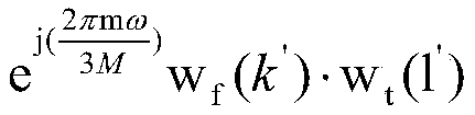 即表示对应RE上第一DMRS的OCC码。其中,m=0时,所在的RB为分配给发送设备的M个RB中所有最小的RB(即第一个RB)。偏移位置c用于表征第一时频资源在第二时频资源上的位置。
其中,ω为常数且0<ω<3M,例如ω可以取1,2,3,4,5中任一项。另外,w
f(k′),w
t(l′)、Δ以及ω的取值可由预定义的配置信息确定。示例性的,可以将上文表1更新为下表4。根据下表4可以确定configuration type 1下,w
f(k′),w
t(l′)、Δ以及ω的取值:
表4

其中,DMRS端口0-7的OCC与偏移位置c以及相移因子ω无关,即DMRS端口0-7不适用c以及ω,因此,表3中DMRS端口0-7对应的c以及ω为N/A。
也就是说,上述方式二可以理解为是通过预定义的配置信息(如表4)中第一DMRS端口对应的偏移位置c来确定第一DMRS的OCC。
方式三:与方式二类似,当DMRS配置为configuration type 1,第二DMRS端口为上述表1中的DMRS端口时,可以利用上文公式(7)将第一DMRS端口的DMRS序列r(n)映射到各RE上。与方式二不同的是,方式三中ω的取值需要预定义的配置信息来确定。示例性的,可以将上文表1更新为下表5。根据下表5可以确定configuration type 1下,w
f(k′),w
t(l′)、Δ、ω以及c的取值:
表5

其中,DMRS端口0-7的OCC与偏移位置c无关,即DMRS端口0-7不适用c,因此,表3中DMRS端口0-7对应的c为N/A。另外,需要说明的是,表5中仅示例性的以ω的取值为2或4为例进行说明,在一些场景中ω还可以取其它值,其取值范围可为0<ω<3M的正整数。
也就是说,上述方式二可以理解为是通过预定义的配置信息(如表5)中第一DMRS端口对应的偏移位置c以及第一DMRS端口对应的相移因子ω值来确定第一DMRS的OCC。
在一种实现方式中,如图8所示,本申请所提供方法还包括:
S203、接收设备发送第一指示信息,以使发送设备接收第一指示信息。
其中,第一指示信息用于向发送设备指示发送设备通过第一时频资源从第一DMRS端口发送第一DMRS。
具体的,第一指示信息具体用于指示第一DMRS的相移因子或第一时频资源在第二时频资源中的位置中至少一项。另外,第一指示信息还可以用于指示第一DMRS的CDM group索引、第一DMRS的频域OCC(即w
f(k′))、第一DMRS的时域OCC(即w
t(l′))等参数。
例如,当发送设备为终端设备,接收设备为网络设备的情况下,通过网络设备向终端设备发送第一指示信息,以使得终端设备确定第一DMRS端口并通过第一时频资源从第一DMRS端口发送第一DMRS。
以下对第一指示信息所指示内容,分为三种情况进行说明:
在第一种情况中,第一指示信息用于指示第一DMRS的相移因子。其中,第一DMRS的相移因子,用于表征第一DMRS的OCC与第二DMRS的OCC中第一时频资源对应的OCC之间的相位差。
示例性的,以上文中采用方式一对将第一DMRS端口的DMRS序列r(n)映射到各 RE上的方式为例,第一指示信息可以用于指示第一DMRS对应的相移因子ω的值。这样一来,在已知第一DMRS对应的ω值、第一DMRS的w
f(k′)、第一DMRS的w
t(l′)以及CDM group索引后,发送设备便可以利用上文公式(6)将第一DMRS端口的DMRS序列r(n)映射到各RE上。
在第二种情况中,第一指示信息用于指示第一时频资源在第二时频资源中的位置。
示例性的,以上文中采用方式二对将第一DMRS端口的DMRS序列r(n)映射到各RE上的方式为例,第一指示信息可以用于指示第一DMRS对应的偏移位置c。这样一来,在已知第一DMRS对应的偏移位置c、第一DMRS的w
f(k′)、第一DMRS的w
t(l′)以及CDM group索引后,由于ω可以为常数,因此发送设备便可以利用上文公式(7)将第一DMRS端口的DMRS序列r(n)映射到各RE上。
在第三种情况中,第一指示信息用于指示第一DMRS的相移因子和第一时频资源在第二时频资源中的位置。
示例性的,以上文中采用方式三对将第一DMRS端口的DMRS序列r(n)映射到各RE上的方式为例,第一指示信息可以用于指示第一DMRS的相移因子和第一时频资源在第二时频资源中的位置。这样一来,在已知第一DMRS对应的ω值、第一DMRS对应的偏移位置c、第一DMRS的w
f(k′)、第一DMRS的w
t(l′)以及CDM group索引后,发送设备便可以利用上文公式(7)将第一DMRS端口的DMRS序列r(n)映射到各RE上。
在一种可能的设计中,上述第一指示信息中包括用于指示第一DMRS端口的端口索引的第一信息。进而,该方法还包括:发送设备根据第一指示信息中的第一信息,确定第一DMRS的相移因子或第一时频资源在第二时频资源中的位置中至少一项。
也就是说,在上述设计中,通过接收设备向发送设备发送包括第一信息的第一指示信息。从而发送设备可以根据第一信息确定确定第一DMRS端口的端口索引,进而根据第一DMRS端口的端口索引确定第一DMRS的相移因子或第一时频资源在第二时频资源中的位置中至少一项,例如,在发送设备中存储有上述表3或表4或表5,进而发送设备在确定第一DMRS端口索引后便可以通过查表确定第一DMRS的相移因子或第一时频资源在第二时频资源中的位置。然后发送设备便可以根据第一DMRS的相移因子或第一时频资源在第二时频资源中的位置中至少一项,将第一DMRS端口的DMRS序列r(n)映射到各RE上,即通过第一时频资源从第一DMRS端口发送第一DMRS。从而达到第一指示信息具体用于指示第一DMRS的相移因子或第一时频资源在第二时频资源中的位置中至少一项的效果。
示例性的,第一指示信息可以为下行控制指示(downlink control indicator,DCI)。即可以在接收设备向发送设备发送的DCI中指示第一DMRS端口索引。
示例一,当发送设备的DMRS端口的秩(rank)为1时,可以利用下表6确定DCI中表征第一指示信息的字段的值(value):
表6

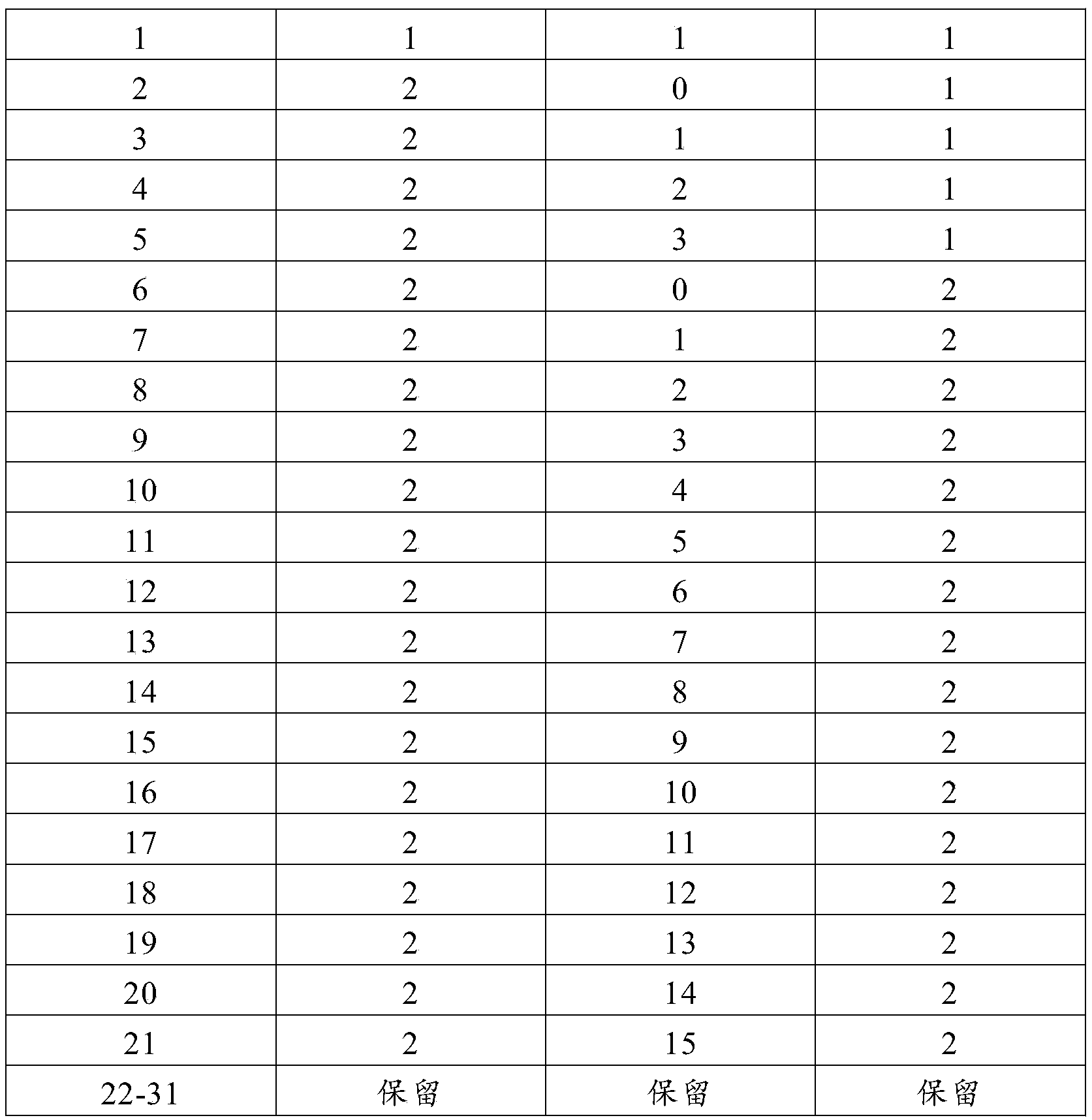
其中,表6中,第一列(value)表示DCI中表征第一指示信息的字段的值;第二列(CDM group个数)表示当前配置的CDM group个数(number of DMRS CDM group(s)without data);第三列(DMRS端口索引)表示为发送设备分配的DMRS端口的端口索引;第四列(前置的DMRS符号个数)表示当前系统配置的前置的DMRS符号个数。
其中,value14-21可以用于指示上文表3或表4或表5中的DMRS端口8-15,即可以用于指示第一DMRS端口。
另外,若按照表6所示方式在DCI中传输上述第一指示信息,则需要占用DCI中5bit。当单独利用一张表指示上文表3或表4或表5中的DMRS端口8-15(下文中简称“DMRS端口8-15”)时,如表7所示:
表7


可以看出,若按照表7所示方式在DCI中传输上述第一指示信息,则需要占用DCI中3bit。
示例二,当发送设备的DMRS端口的秩(rank)为2时,可以利用下表8确定DCI中表征第一指示信息的字段的值(value):
表8

其中,value10-15可以用于指示给发送设备配置的DMRS端中包括DMRS端口8-15,即value10-15可以用于指示第一DMRS端口。
另外,若按照表8所示方式在DCI中传输上述第一指示信息,则需要占用DCI中4bit。当单独利用一张表,用于指示包括DMRS端口8-15的指示时,如表9所示:
表9


可以看出,若按照表9所示方式在DCI中传输上述第一指示信息,则需要占用DCI中3bit。另外,也可以只指示其中部分value,例如只指示表9中value0-3,此时只需要2bit来指示。
示例三,当发送设备的DMRS端口的秩(rank)为3时,可以利用下表10确定DCI中表征第一指示信息的字段的值(value):
表10

其中,value3和value3可以用于指示给发送设备配置的DMRS端中包括DMRS端口8-15。
另外,也可以考虑其他的端口组合,例如表11所示:
表11

另外,还可以单独利用一张表,用于在DCI中传输包括DMRS端口8-15的指示,如表12所示:
表12

示例四,当发送设备的DMRS端口的秩(rank)为4时,可以利用下表13确定DCI中表征第一指示信息的字段的值(value):
表13

另外,还可以单独利用一张表,用于在DCI中传输包括DMRS端口8-15的指示,如表14所示:
表14

可以看出,若按照表13所示方式在DCI中传输上述第一指示信息,则需要占用DCI中2bit。
在另一种实现方式中,如图9所示,本申请所提供方法还包括:
S204、发送设备向接收设备发送第二指示信息。
其中,第二指示信息用于指示接收设备通过第一时频资源从第一DMRS端口接收第一DMRS。
具体的,第二指示信息具体用于指示第一DMRS的相移因子或第一时频资源在第二时频资源中的位置中至少一项。
例如,当发送设备为网络设备,接收设备为终端设备的情况下,通过网络设备向终端设备发送第二指示信息,以使得终端设备确定第一DMRS端口并通过第一时频资源从第一DMRS端口接收第一DMRS。
其中,第二指示信息的所指示内容的具体实现方式,可参照上文S203中对第一指示信息所指示内容的说明,在此不再赘述。
以下对发送设备通过多个DMRS端口分别向接收设备发送DMRS时,本申请所提供方法的实现过程进行介绍。需要说明的是,以下介绍中主要以发送设备通过三个DMRS端口分别向接收设备发送DMRS的实现过程进行介绍,可以理解的是相关描述也可应用于发送设备通过四个或四个以上DMRS端口分别向接收设备发送DMRS的实现过程:
在一种实现方式中,如图10所示,该方法还包括:
S205、发送设备通过第一时频资源从第三DMRS端口发送第三DMRS。
进而,接收设备可以通过第一时频资源从第三DMRS端口接收第三DMRS。
其中,第三DMRS的正交掩码OCC与第二DMRS的OCC中第一时频资源对应的OCC正交。
在一种可能的设计中,当第一DMRS的OCC与第二DMRS的OCC中第一时频资源对应的OCC,满足
 (即上文公式(5))的情况下,第三DMRS的OCC与第二DMRS的OCC中第一时频资源对应的OCC,满足以下公式(7):
其中,s
3(m)表示第三DMRS的OCC中的第m项,s
2(m)表示第二DMRS的OCC中第一时频资源对应的OCC中的第m项;M表示承载第二时频资源的RB中用于通过循环移位确定第一DMRS的OCC的第二DMRS所对应的RB的个数,M为2的倍数;ω
2表示第三DMRS的相移因子,ω
1与ω
2不同。
上述实现方式中,考虑到当采用通过对特定DMRS端口(即第二DMRS端口)的DMRS(即第二DMRS)的OCC进行循环移位,来得到另一DMRS端口(即第一DMRS端口)的DMRS(即第一DMRS)的OCC的情况下,可以通过采用不同相移因子ω,得到多种不同的OCC。这些多种不同的OCC所对应的DMRS的OCC,都可以与原特定DMRS端口的DMRS的OCC保持正交。因此,通过上述实现方式可以在第一DMRS端口以及第二DMRS端口复用的第一时频资源上,传输不对第一DMRS端口和第二DMRS端口产生干扰的第三DMRS。从而达到不增加分配给DMRS的时频资源开销的情况下,进一步增加系统所支持的正交DMRS端口的数量。
在另一种实现方式中,如图11所示,该方法还可以包括:
S206、发送设备通过第三时频资源从第四DMRS端口发送第四DMRS。
其中,第三时频资源包含于第二时频资源,第三时频资源与第一时频资源不重叠。第四DMRS的OCC与第二DMRS的OCC中第三时频资源对应的OCC正交。
也就是说,本申请所提供方法中,还可以由第四DMRS端口复用第二DMRS端口的第二时频资源中除第一时频资源之外的部分时频资源(即第三时频资源),从而进一步增加系统支持的正交DMRS端口的个数。
具体的,其中第四DMRS的的OCC与第二DMRS的OCC中第三时频资源对应的OCC正交的具体实现方式,可以参照上文中第一DMRS的的OCC与第二DMRS的OCC中第一时频资源对应的OCC正交的相应描述,在此不再赘述。
在一种可能的设计中,第二时频资源所包含子载波个数是第三时频资源所包含子载波个数的P倍,P为大于1的整数。在时域的一个OFDM符号上,第三时频资源包括:第二时频资源包含的子载波中等间隔分布的子载波集合。其中,子载波集合中相邻两个子载波之间间隔P个第二时频资源所包含的子载波。
示例性的,第二DMRS端口可以为上述表4中的DMRS端口0,第一DMRS可以为上述表4中的DMRS端口8,第四DMRS可以为上述表4中的DMRS端口9。以两个RB(即连续24个子载波)为例,则第二DMRS的OCC、第一DMRS的OCC、第四DMRS的OCC在两个RB上各RE的值如下表15所示:
表15

上述实现方式中,通过在第二时频资源中除第一时频资源之外的第三时频资源上传输不对第一DMRS端口和第二DMRS端口产生干扰的第四DMRS端口的第四DMRS。从而达到不增加分配给DMRS的时频资源开销的情况下,进一步增加系统所支持的正交DMRS端口的数量。
可以理解的,本申请实施例中,接收设备和/或发送设备可以执行本申请实施例中的部分或全部步骤,这些步骤或操作仅是示例,本申请实施例中,还可以执行其它操作或者各种操作的变形。此外,各个步骤可以按照本申请实施例呈现的不同的顺序来执行,并且有可能并非要执行本申请实施例中的全部操作。本申请提供的实施例之间是可以关联的,并且可以相互参考或引用。
以上实施例主要从设备之间交互的角度对本申请实施例提供的方案进行了介绍。应理解,上述接收设备或发送设备为了实现对应的功能,其包括了执行各功能相应的硬件结构和/或软件模块。本领域技术人员应该很容易意识到,结合本文中所公开的实施例描述的各示例的单元,本申请能够以硬件或硬件和计算机软件的结合形式来实现。 某个功能究竟以硬件还是计算机软件驱动硬件的方式来执行,取决于技术方案的特定应用和设计约束条件。专业技术人员可以对每个特定的应用来使用不同方法来实现所描述的功能,但是这种实现不应认为超出本申请的范围。
本申请实施例可以根据上述方法示例对设备(接收设备或发送设备)进行功能模块的划分,例如,可以对应各个功能划分各个功能模块,也可以将两个或两个以上的功能集成在一个处理模块中。上述集成的模块既可以采用硬件的形式实现,也可以采用软件功能模块的形式实现。可选的,本申请实施例中对模块的划分是示意性的,仅仅为一种逻辑功能划分,实际实现时可以有另外的划分方式。
如图12所示,为本申请实施例提供的一种通信装置30的组成示意图。通信装置30可以是接收设备中的芯片或片上系统。该通信装置30可以用于执行上述实施例中设计的接收设备的功能。作为一种可实现方式,该通信装置30包括:
接收单元301,用于通过第一时频资源从第一解调参考信号DMRS端口接收第一DMRS,通过第二时频资源从第二DMRS端口接收第二DMRS。
其中,所述第一时频资源是所述第二时频资源中的部分时频资源,所述第一DMRS的正交掩码OCC与所述第二DMRS的OCC中所述第一时频资源对应的OCC正交。
在一种实现方式中,所述第一DMRS的正交掩码OCC,与所述第二DMRS的OCC中所述第一时频资源对应的OCC进行循环移位后的结果相同。
在一种实现方式中,所述第二时频资源所包含子载波个数是所述第一时频资源所包含子载波的个数的P倍;P为大于1的整数;在时域的一个正交频分复用OFDM符号上,所述第一时频资源包括:所述第二时频资源所包含的子载波中等间隔分布的子载波集合;其中,所述子载波集合中相邻两个子载波之间间隔P-1个所述第二时频资源所包含的子载波。
在一种实现方式中,P=2;所述第一DMRS的OCC与所述第二DMRS的OCC中所述第一时频资源对应的OCC,满足以下公式一:
其中,s
1(m)表示所述第一DMRS的OCC中的第m项,s
2(m)表示所述第二DMRS的OCC中所述第一时频资源对应的OCC中的第m项;M表示承载所述第二时频资源的资源块RB中用于通过循环移位确定所述第一DMRS的OCC的第二DMRS所对应的RB的个数,M为2的倍数;ω
1表示所述第一DMRS的相移因子。
在一种实现方式中,接收单元301,还用于通过所述第一时频资源从第三DMRS端口接收第三DMRS;所述第三DMRS的OCC与所述第二DMRS的OCC中所述第一时频资源对应的OCC,满足以下公式二:
其中,s
3(m)表示所述第三DMRS的OCC中的第m项,s
2(m)表示所述第二DMRS的OCC中所述第一时频资源对应的OCC中的第m项;M表示承载所述第二时频资源的RB中用于通过循环移位确定所述第一DMRS的OCC的第二DMRS所对应的RB的个数,M为2的倍数;ω
2表示所述第三DMRS的相移因子,ω
2与ω
1不同。
在一种实现方式中,接收单元301,还用于通过第三时频资源从第四DMRS端口 接收第四DMRS;所述第三时频资源包含于所述第二时频资源,所述第三时频资源与所述第一时频资源不重叠;所述第四DMRS的正交掩码OCC与第二DMRS的OCC中所述第三时频资源对应的OCC正交。
在一种实现方式中,所述第二时频资源所包含子载波个数是所述第三时频资源所包含子载波的个数的P倍;P为大于1的整数;在时域的一个OFDM符号上,所述第三时频资源包括:所述第二时频资源所包含的子载波中等间隔分布的子载波集合;其中,所述子载波集合中相邻两个子载波之间间隔P-1个所述第二时频资源所包含的子载波。
在一种实现方式中,所述通信装置30还包括发送单元302;所述发送单元302,用于发送第一指示信息;所述第一指示信息,用于向发送设备指示所述第一DMRS的相移因子或所述第一时频资源在所述第二时频资源中的位置中至少一项;所述第一DMRS的相移因子,用于表征所述第一DMRS的OCC与所述第二DMRS的OCC中所述第一时频资源对应的OCC之间的相位差;所述发送设备为通过所述第一时频资源从所述第一DMRS端口发送所述第一DMRS的设备;
在一种实现方式中,所述接收单元301,还用于接收来自发送设备的第二指示信息;所述第二指示信息,用于指示所述第一DMRS的相移因子或所述第一时频资源在所述第二时频资源中的位置中至少一项;所述第一DMRS的相移因子,用于表征所述第一DMRS的OCC与所述第二DMRS的OCC中所述第一时频资源对应的OCC之间的相位差;所述发送设备为通过所述第一时频资源从所述第一DMRS端口发送所述第一DMRS的设备。
可以理解,关于上述通信装置30中的各个单元的功能的具体描述可以参照方法实施例,例如图6或图8-图10所示实施例中对应的接收设备执行的相关步骤的描述,在此不做赘述。
如图13所示,为本申请实施例提供的另一种通信装置40的组成示意图。该通信装置40可以是发送设备中的芯片或片上系统。该通信装置40可以用于执行上述实施例中涉及的发送设备的功能。作为一种可实现方式,该通信装置40包括:
发送单元401,用于通过第一时频资源从第一解调参考信号DMRS端口发送第一DMRS;其中,所述第一时频资源包含于第二时频资源,所述第二时频资源为用于映射所述第二DMRS端口的第二DMRS的时频资源,所述第一DMRS的正交掩码OCC与第二DMRS的OCC中所述第一时频资源对应的OCC正交。
在一种实现方式中,所述第一DMRS的正交掩码OCC与第二DMRS的OCC中所述第一时频资源对应的OCC进行循环移位后的结果相同。
在一种实现方式中,所述第二时频资源所包含子载波个数是所述第一时频资源所包含子载波的个数的P倍;P为大于1的整数;在时域的一个正交频分复用OFDM符号上,所述第一时频资源包括:所述第二时频资源所包含的子载波中等间隔分布的子载波集合;其中,所述子载波集合中相邻两个子载波之间间隔P-1个所述第二时频资源所包含的子载波。
在一种实现方式中,P=2;所述第一DMRS的OCC与所述第二DMRS的OCC中所述第一时频资源对应的OCC,满足以下公式一:
其中,s
1(m)表示所述第一DMRS的OCC中的第m项,s
2(m)表示所述第二DMRS的OCC中所述第一时频资源对应的OCC中的第m项;M表示承载所述第二时频资源的资源块RB中用于通过循环移位确定所述第一DMRS的OCC的第二DMRS所对应的RB的个数,M为2的倍数;ω
1表示所述第一DMRS的相移因子。
在一种实现方式中,所述发送单元401,还用于通过所述第一时频资源从第三DMRS端口发送第三DMRS;其中,所述第三DMRS的OCC与所述第二DMRS的OCC中所述第一时频资源对应的OCC,满足以下公式二:
其中,s
3(m)表示所述第三DMRS的OCC中的第m项,s
2(m)表示所述第二DMRS的OCC中所述第一时频资源对应的OCC中的第m项;M表示承载所述第二时频资源的资源块RB中用于通过循环移位确定所述第一DMRS的OCC的第二DMRS所对应的RB的个数,M为2的倍数;ω
2表示所述第三DMRS的相移因子,ω
1与ω
2不同。
在一种实现方式中,所述发送单元401,还用于通过第三时频资源从第三DMRS端口发送第三DMRS;其中,所述第三时频资源包含于所述第二时频资源并且所述第三时频资源与所述第一时频资源不重叠,所述第三DMRS的正交掩码OCC与第二DMRS的OCC中所述第三时频资源对应的OCC正交。
在一种实现方式中,所述第二时频资源所包含子载波个数是所述第三时频资源所包含子载波的个数的P倍;P为大于1的整数;在时域的一个OFDM符号上,所述第三时频资源包括:所述第二时频资源所包含的子载波中等间隔分布的子载波集合;其中,所述子载波集合中相邻两个子载波之间间隔P-1个所述第二时频资源所包含的子载波。
在一种实现方式中,该通信装置还包括接收单元402;所述接收单元402,用于接收第一指示信息;所述第一指示信息,用于指示所述第一DMRS的相移因子或所述第一时频资源在所述第二时频资源中的位置中至少一项;所述第一DMRS的相移因子,用于表征所述第一DMRS的OCC与所述第二DMRS的OCC中所述第一时频资源对应的OCC之间的相位差;
在一种实现方式中,所述发送单元401,还用于发送第二指示信息;所述第二指示信息,用于向接收设备指示所述第一DMRS的相移因子或所述第一时频资源在所述第二时频资源中的位置中至少一项;所述第一DMRS的相移因子,用于表征所述第一DMRS的OCC与所述第二DMRS的OCC中所述第一时频资源对应的OCC之间的相位差;所述接收设备为通过所述第一时频资源从所述第一DMRS端口接收所述第一DMRS的设备。
可以理解,关于上述通信装置40中的各个单元的功能的具体描述可以参照方法实施例,例如图6或图8-图10所示实施例中对应的发送设备执行的相关步骤的描述,在此不做赘述。
如图14示出了一种通信装置50的组成示意图。其中,通信装置50包括:至少一个处理器501,以及至少一个接口电路504。另外,该通信装置50还可以包括通信线 路502,存储器503。
处理器501可以是一个通用中央处理器(central processing unit,CPU),微处理器,特定应用集成电路(application-specific integrated circuit,ASIC),或一个或多个用于控制本申请方案程序执行的集成电路。
通信线路502可包括一通路,在上述组件之间传送信息。
接口电路504,使用任何收发器一类的装置,用于与其他设备或通信网络通信,如以太网,无线接入网(radio access network,RAN),无线局域网(wireless local area networks,WLAN)等。
存储器503可以是只读存储器(read-only memory,ROM)或可存储静态信息和指令的其他类型的静态存储设备,随机存取存储器(random access memory,RAM)或者可存储信息和指令的其他类型的动态存储设备,也可以是电可擦可编程只读存储器(electrically erasable programmable read-only memory,EEPROM)、只读光盘(compact disc read-only memory,CD-ROM)或其他光盘存储、光碟存储(包括压缩光碟、激光碟、光碟、数字通用光碟、蓝光光碟等)、磁盘存储介质或者其他磁存储设备、或者能够用于携带或存储具有指令或数据结构形式的程序代码并能够由计算机存取的任何其他介质,但不限于此。存储器可以是独立存在,通过通信线路502与处理器相连接。存储器也可以和处理器集成在一起。
其中,存储器503用于存储执行本申请方案的计算机执行指令,并由处理器501来控制执行。处理器501用于执行存储器503中存储的计算机执行指令,从而实现本申请实施例提供的通信方法。
示例性地,在一些实施例中,当处理器501执行存储器503存储的指令时,使得该通信装置50执行如图6或图8-图10所示中接收设备需要执行的操作。
在另一些实施例中,当处理器501执行存储器503存储的指令时,使得该通信装置50执行如图6或图8-图10所示中发送设备需要执行的操作。
可选的,本申请实施例中的计算机执行指令也可以称之为应用程序代码,本申请实施例对此不作具体限定。
在具体实现中,作为一种实施例,处理器501可以包括一个或多个CPU,例如图14中的CPU0和CPU1。
在具体实现中,作为一种实施例,装置50可以包括多个处理器,例如图14中的处理器501和处理器507。这些处理器中的每一个可以是一个单核(single-CPU)处理器,也可以是一个多核(multi-CPU)处理器。这里的处理器可以指一个或多个设备、电路、和/或用于处理例如计数据(算机程序指令)的处理核。
在具体实现中,作为一种实施例,装置50还可以包括输出设备505和输入设备506。输出设备505和处理器501通信,可以以多种方式来显示信息。例如,输出设备505可以是液晶显示器(liquid crystal display,LCD),发光二级管(light emitting diode,LED)显示设备,阴极射线管(cathode ray tube,CRT)显示设备,或投影仪(projector)等。输入设备506和处理器501通信,可以以多种方式接收用户的输入。例如,输入设备506可以是鼠标、键盘、触摸屏设备或传感设备等。
本申请实施例还提供一种计算机可读存储介质,该计算机可读存储介质中存储有 指令,当该指令运行时,执行本申请实施例所提供的方法。示例性地,当该指令运行时,执行如图6或图8-图10所示中接收设备需要执行的操作。或者,当该指令运行时,执行如图6或图8-图10所示中发送设备需要执行的其他操作。
本申请实施例还提供一种包含指令的计算机程序产品。当其在计算机上运行时,使得计算机可以执行本申请实施例所提供的方法。示例性地,当该包含指令的计算机程序产品在计算机上运行时,计算机可以如图6或图8-图10所示中接收设备需要执行的操作。或者,当该包含指令的计算机程序产品在计算机上运行时,计算机可以如图6或图8-图10所示中发送设备需要执行的其他操作。
本申请实施例还提供一种芯片。该芯片包括处理电路和接口;处理电路用于从存储介质中调用并运行存储介质中存储的计算机程序,使得芯片可以执行本申请实施例提供的方法。
本申请实施例还提供一种通信系统,包括接收设备和发送设备;其中:所述接收设备,用于执行上述实施例中接收设备所执行的操作,例如执行如图6或图8-图10所示中接收设备需要执行的操作;所述发送设备,用于执行上述实施例中发送设备所执行的操作,例如执行如图6或图8-图10所示中发送设备需要执行的操作。
在上述实施例中的功能或动作或操作或步骤等,可以全部或部分地通过软件、硬件、固件或者其任意组合来实现。当使用软件程序实现时,可以全部或部分地以计算机程序产品的形式来实现。该计算机程序产品包括一个或多个计算机指令。在计算机上加载和执行计算机程序指令时,全部或部分地产生按照本申请实施例所述的流程或功能。所述计算机可以是通用计算机、专用计算机、计算机网络、或者其他可编程装置。所述计算机指令可以存储在计算机可读存储介质中,或者从一个计算机可读存储介质向另一个计算机可读存储介质传输,例如,所述计算机指令可以从一个网站站点、计算机、服务器或者数据中心通过有线(例如同轴电缆、光纤、数字用户线(digital subscriber line,DSL))或无线(例如红外、无线、微波等)方式向另一个网站站点、计算机、服务器或数据中心进行传输。所述计算机可读存储介质可以是计算机能够存取的任何可用介质或者是包括一个或多个可以用介质集成的服务器、数据中心等数据存储设备。所述可用介质可以是磁性介质(例如,软盘、硬盘、磁带),光介质(例如,DVD)、或者半导体介质(例如固态硬盘(solid state disk,SSD))等。
尽管结合具体特征及其实施例对本申请进行了描述,显而易见的,在不脱离本申请的精神和范围的情况下,可对其进行各种修改和组合。相应地,本说明书和附图仅仅是所附权利要求所界定的本申请的示例性说明,且视为已覆盖本申请范围内的任意和所有修改、变化、组合或等同物。显然,本领域的技术人员可以对本申请进行各种改动和变型而不脱离本申请的范围。这样,倘若本申请的这些修改和变型属于本申请权利要求及其等同技术的范围之内,则本申请也意图包括这些改动和变型在内。
Claims (38)
- 一种通信方法,其特征在于,所述方法包括:接收设备通过第一时频资源从第一解调参考信号DMRS端口接收第一DMRS,通过第二时频资源从第二DMRS端口接收第二DMRS;其中,所述第一时频资源是所述第二时频资源中的部分时频资源,所述第一DMRS的正交掩码OCC与所述第二DMRS的OCC中所述第一时频资源对应的OCC正交。
- 根据权利要求1所述的方法,其特征在于,所述第一DMRS的正交掩码OCC,与所述第二DMRS的OCC中所述第一时频资源对应的OCC进行循环移位后的结果相同。
- 根据权利要求1或2所述的方法,其特征在于,所述第二时频资源所包含子载波个数是所述第一时频资源所包含子载波的个数的P倍;P为大于1的整数;在时域的一个正交频分复用OFDM符号上,所述第一时频资源包括:所述第二时频资源所包含的子载波中等间隔分布的子载波集合;其中,所述子载波集合中相邻两个子载波之间间隔P-1个所述第二时频资源所包含的子载波。
- 根据权利要求3所述的方法,其特征在于,P=2;所述第一DMRS的OCC与所述第二DMRS的OCC中所述第一时频资源对应的OCC,满足以下公式一:
 其中,s 1(m)表示所述第一DMRS的OCC中的第m项,s 2(m)表示所述第二DMRS的OCC中所述第一时频资源对应的OCC中的第m项;M表示承载所述第二时频资源的资源块RB中用于通过循环移位确定所述第一DMRS的OCC的第二DMRS所对应的RB的个数,M为2的倍数;ω 1表示所述第一DMRS的相移因子。
 - 根据权利要求4所述的方法,其特征在于,所述方法还包括:所述接收设备通过所述第一时频资源从第三DMRS端口接收第三DMRS;所述第三DMRS的OCC与所述第二DMRS的OCC中所述第一时频资源对应的OCC,满足以下公式二:
 其中,s 3(m)表示所述第三DMRS的OCC中的第m项,s 2(m)表示所述第二DMRS的OCC中所述第一时频资源对应的OCC中的第m项;M表示承载所述第二时频资源的RB中用于通过循环移位确定所述第一DMRS的OCC的第二DMRS所对应的RB的个数,M为2的倍数;ω 2表示所述第三DMRS的相移因子,ω 2与ω 1不同。
 - 根据权利要求1-5任一项所述的方法,其特征在于,所述方法还包括:所述接收设备通过第三时频资源从第四DMRS端口接收第四DMRS;所述第三时频资源包含于所述第二时频资源,所述第三时频资源与所述第一时频资源不重叠;所述第四DMRS的正交掩码OCC与第二DMRS的OCC中所述第三时频资源对应的OCC正交。
- 根据权利要求6所述的方法,其特征在于,所述第二时频资源所包含子载波个数是所述第三时频资源所包含子载波的个数的P倍;P为大于1的整数;在时域的一个OFDM符号上,所述第三时频资源包括:所述第二时频资源所包含 的子载波中等间隔分布的子载波集合;其中,所述子载波集合中相邻两个子载波之间间隔P-1个所述第二时频资源所包含的子载波。
- 根据权利要求1-7任一项所述的方法,其特征在于,所述方法还包括:所述接收设备发送第一指示信息;所述第一指示信息,用于向发送设备指示所述第一DMRS的相移因子或所述第一时频资源在所述第二时频资源中的位置中至少一项;所述第一DMRS的相移因子,用于表征所述第一DMRS的OCC与所述第二DMRS的OCC中所述第一时频资源对应的OCC之间的相位差;所述发送设备为通过所述第一时频资源从所述第一DMRS端口发送所述第一DMRS的设备;或者,所述方法还包括:所述接收设备接收来自发送设备的第二指示信息;所述第二指示信息,用于指示所述第一DMRS的相移因子或所述第一时频资源在所述第二时频资源中的位置中至少一项;所述第一DMRS的相移因子,用于表征所述第一DMRS的OCC与所述第二DMRS的OCC中所述第一时频资源对应的OCC之间的相位差;所述发送设备为通过所述第一时频资源从所述第一DMRS端口发送所述第一DMRS的设备。
- 一种通信方法,其特征在于,所述方法包括:发送设备通过第一时频资源从第一解调参考信号DMRS端口发送第一DMRS;其中,所述第一时频资源包含于第二时频资源,所述第二时频资源为用于映射第二DMRS端口的第二DMRS的时频资源,所述第一DMRS的正交掩码OCC与第二DMRS的OCC中所述第一时频资源对应的OCC正交。
- 根据权利要求9所述的方法,其特征在于,所述第一DMRS的正交掩码OCC与第二DMRS的OCC中所述第一时频资源对应的OCC进行循环移位后的结果相同。
- 根据权利要求9或10所述的方法,其特征在于,所述第二时频资源所包含子载波个数是所述第一时频资源所包含子载波的个数的P倍;P为大于1的整数;在时域的一个正交频分复用OFDM符号上,所述第一时频资源包括:所述第二时频资源所包含的子载波中等间隔分布的子载波集合;其中,所述子载波集合中相邻两个子载波之间间隔P-1个所述第二时频资源所包含的子载波。
- 根据权利要求11所述的方法,其特征在于,P=2;所述第一DMRS的OCC与所述第二DMRS的OCC中所述第一时频资源对应的OCC,满足以下公式一:
 其中,s 1(m)表示所述第一DMRS的OCC中的第m项,s 2(m)表示所述第二DMRS的OCC中所述第一时频资源对应的OCC中的第m项;M表示承载所述第二时频资源的资源块RB中用于通过循环移位确定所述第一DMRS的OCC的第二DMRS所对应的RB的个数,M为2的倍数;ω 1表示所述第一DMRS的相移因子。
 - 根据权利要求12所述的方法,其特征在于,所述方法还包括:所述发送设备通过所述第一时频资源从第三DMRS端口发送第三DMRS;其中,所述第三DMRS的OCC与所述第二DMRS的OCC中所述第一时频资源对应的OCC,满足以下公式二:
 其中,s 3(m)表示所述第三DMRS的OCC中的第m项,s 2(m)表示所述第二DMRS的OCC中所述第一时频资源对应的OCC中的第m项;M表示承载所述第二时频资源的资源块RB中用于通过循环移位确定所述第一DMRS的OCC的第二DMRS所对应的RB的个数,M为2的倍数;ω 2表示所述第三DMRS的相移因子,ω 1与ω 2不同。
 - 根据权利要求9-13任一项所述的方法,其特征在于,所述方法还包括:所述发送设备通过第三时频资源从第三DMRS端口发送第三DMRS;其中,所述第三时频资源包含于所述第二时频资源并且所述第三时频资源与所述第一时频资源不重叠,所述第三DMRS的正交掩码OCC与第二DMRS的OCC中所述第三时频资源对应的OCC正交。
- 根据权利要求14所述的方法,其特征在于,所述第二时频资源所包含子载波个数是所述第三时频资源所包含子载波的个数的P倍;P为大于1的整数;在时域的一个OFDM符号上,所述第三时频资源包括:所述第二时频资源所包含的子载波中等间隔分布的子载波集合;其中,所述子载波集合中相邻两个子载波之间间隔P-1个所述第二时频资源所包含的子载波。
- 根据权利要求9-15任一项所述的方法,其特征在于,所述方法还包括:所述发送设备接收第一指示信息;所述第一指示信息,用于指示所述第一DMRS的相移因子或所述第一时频资源在所述第二时频资源中的位置中至少一项;所述第一DMRS的相移因子,用于表征所述第一DMRS的OCC与所述第二DMRS的OCC中所述第一时频资源对应的OCC之间的相位差;或者,所述方法还包括:所述发送设备发送第二指示信息;所述第二指示信息,用于向接收设备指示所述第一DMRS的相移因子或所述第一时频资源在所述第二时频资源中的位置中至少一项;所述第一DMRS的相移因子,用于表征所述第一DMRS的OCC与所述第二DMRS的OCC中所述第一时频资源对应的OCC之间的相位差;所述接收设备为通过所述第一时频资源从所述第一DMRS端口接收所述第一DMRS的设备。
- 一种通信装置,其特征在于,所述通信装置包括:接收单元,用于通过第一时频资源从第一解调参考信号DMRS端口接收第一DMRS,通过第二时频资源从第二DMRS端口接收第二DMRS;其中,所述第一时频资源是所述第二时频资源中的部分时频资源,所述第一DMRS的正交掩码OCC与所述第二DMRS的OCC中所述第一时频资源对应的OCC正交。
- 根据权利要求17所述的通信装置,其特征在于,所述第一DMRS的正交掩码OCC,与所述第二DMRS的OCC中所述第一时频资源对应的OCC进行循环移位后的结果相同。
- 根据权利要求17或18所述的通信装置,其特征在于,所述第二时频资源所包含子载波个数是所述第一时频资源所包含子载波的个数的P倍;P为大于1的整数;在时域的一个正交频分复用OFDM符号上,所述第一时频资源包括:所述第二时频资源所包含的子载波中等间隔分布的子载波集合;其中,所述子载波集合中相邻两个子载波之间间隔P-1个所述第二时频资源所包含的子载波。
- 根据权利要求19所述的通信装置,其特征在于,P=2;所述第一DMRS的 OCC与所述第二DMRS的OCC中所述第一时频资源对应的OCC,满足以下公式一:
 其中,s 1(m)表示所述第一DMRS的OCC中的第m项,s 2(m)表示所述第二DMRS的OCC中所述第一时频资源对应的OCC中的第m项;M表示承载所述第二时频资源的资源块RB中用于通过循环移位确定所述第一DMRS的OCC的第二DMRS所对应的RB的个数,M为2的倍数;ω 1表示所述第一DMRS的相移因子。
 - 根据权利要求20所述的通信装置,其特征在于,所述接收单元,还用于通过所述第一时频资源从第三DMRS端口接收第三DMRS;所述第三DMRS的OCC与所述第二DMRS的OCC中所述第一时频资源对应的OCC,满足以下公式二:
 其中,s 3(m)表示所述第三DMRS的OCC中的第m项,s 2(m)表示所述第二DMRS的OCC中所述第一时频资源对应的OCC中的第m项;M表示承载所述第二时频资源的RB中用于通过循环移位确定所述第一DMRS的OCC的第二DMRS所对应的RB的个数,M为2的倍数;ω 2表示所述第三DMRS的相移因子,ω 2与ω 1不同。
 - 根据权利要求17-21任一项所述的通信装置,其特征在于,所述接收单元,还用于通过第三时频资源从第四DMRS端口接收第四DMRS;所述第三时频资源包含于所述第二时频资源,所述第三时频资源与所述第一时频资源不重叠;所述第四DMRS的正交掩码OCC与第二DMRS的OCC中所述第三时频资源对应的OCC正交。
- 根据权利要求22所述的通信装置,其特征在于,所述第二时频资源所包含子载波个数是所述第三时频资源所包含子载波的个数的P倍;P为大于1的整数;在时域的一个OFDM符号上,所述第三时频资源包括:所述第二时频资源所包含的子载波中等间隔分布的子载波集合;其中,所述子载波集合中相邻两个子载波之间间隔P-1个所述第二时频资源所包含的子载波。
- 根据权利要求17-23任一项所述的通信装置,其特征在于,所述通信装置还包括发送单元;所述发送单元,用于发送第一指示信息;所述第一指示信息,用于向发送设备指示所述第一DMRS的相移因子或所述第一时频资源在所述第二时频资源中的位置中至少一项;所述第一DMRS的相移因子,用于表征所述第一DMRS的OCC与所述第二DMRS的OCC中所述第一时频资源对应的OCC之间的相位差;所述发送设备为通过所述第一时频资源从所述第一DMRS端口发送所述第一DMRS的设备;或者,所述接收单元,还用于接收来自发送设备的第二指示信息;所述第二指示信息,用于指示所述第一DMRS的相移因子或所述第一时频资源在所述第二时频资源中的位置中至少一项;所述第一DMRS的相移因子,用于表征所述第一DMRS的OCC与所述第二DMRS的OCC中所述第一时频资源对应的OCC之间的相位差;所述发送设备为通过所述第一时频资源从所述第一DMRS端口发送所述第一DMRS的设备。
- 一种通信装置,其特征在于,所述通信装置包括:发送单元,用于通过第一时频资源从第一解调参考信号DMRS端口发送第一 DMRS;其中,所述第一时频资源包含于第二时频资源,所述第二时频资源为用于映射第二DMRS端口的第二DMRS的时频资源,所述第一DMRS的正交掩码OCC与第二DMRS的OCC中所述第一时频资源对应的OCC正交。
- 根据权利要求25所述的通信装置,其特征在于,所述第一DMRS的正交掩码OCC与第二DMRS的OCC中所述第一时频资源对应的OCC进行循环移位后的结果相同。
- 根据权利要求24或25所述的通信装置,其特征在于,所述第二时频资源所包含子载波个数是所述第一时频资源所包含子载波的个数的P倍;P为大于1的整数;在时域的一个正交频分复用OFDM符号上,所述第一时频资源包括:所述第二时频资源所包含的子载波中等间隔分布的子载波集合;其中,所述子载波集合中相邻两个子载波之间间隔P-1个所述第二时频资源所包含的子载波。
- 根据权利要求27所述的通信装置,其特征在于,P=2;所述第一DMRS的OCC与所述第二DMRS的OCC中所述第一时频资源对应的OCC,满足以下公式一:
 其中,s 1(m)表示所述第一DMRS的OCC中的第m项,s 2(m)表示所述第二DMRS的OCC中所述第一时频资源对应的OCC中的第m项;M表示承载所述第二时频资源的资源块RB中用于通过循环移位确定所述第一DMRS的OCC的第二DMRS所对应的RB的个数,M为2的倍数;ω 1表示所述第一DMRS的相移因子。
 - 根据权利要求28所述的通信装置,其特征在于,所述发送单元,还用于通过所述第一时频资源从第三DMRS端口发送第三DMRS;其中,所述第三DMRS的OCC与所述第二DMRS的OCC中所述第一时频资源对应的OCC,满足以下公式二:
 其中,s 3(m)表示所述第三DMRS的OCC中的第m项,s 2(m)表示所述第二DMRS的OCC中所述第一时频资源对应的OCC中的第m项;M表示承载所述第二时频资源的资源块RB中用于通过循环移位确定所述第一DMRS的OCC的第二DMRS所对应的RB的个数,M为2的倍数;ω 2表示所述第三DMRS的相移因子,ω 1与ω 2不同。
 - 根据权利要求25-29任一项所述的通信装置,其特征在于,所述发送单元,还用于通过第三时频资源从第三DMRS端口发送第三DMRS;其中,所述第三时频资源包含于所述第二时频资源并且所述第三时频资源与所述第一时频资源不重叠,所述第三DMRS的正交掩码OCC与第二DMRS的OCC中所述第三时频资源对应的OCC正交。
- 根据权利要求30所述的通信装置,其特征在于,所述第二时频资源所包含子载波个数是所述第三时频资源所包含子载波的个数的P倍;P为大于1的整数;在时域的一个OFDM符号上,所述第三时频资源包括:所述第二时频资源所包含的子载波中等间隔分布的子载波集合;其中,所述子载波集合中相邻两个子载波之间间隔P-1个所述第二时频资源所包含的子载波。
- 根据权利要求25-31任一项所述的通信装置,其特征在于,所述通信装置还包括接收单元;所述接收单元,用于接收第一指示信息;所述第一指示信息,用于指示所述第一DMRS的相移因子或所述第一时频资源在所述第二时频资源中的位置中至少一项;所述第一DMRS的相移因子,用于表征所述第一DMRS的OCC与所述第二DMRS的OCC中所述第一时频资源对应的OCC之间的相位差;或者,所述发送单元,还用于发送第二指示信息;所述第二指示信息,用于向接收设备指示所述第一DMRS的相移因子或所述第一时频资源在所述第二时频资源中的位置中至少一项;所述第一DMRS的相移因子,用于表征所述第一DMRS的OCC与所述第二DMRS的OCC中所述第一时频资源对应的OCC之间的相位差;所述接收设备为通过所述第一时频资源从所述第一DMRS端口接收所述第一DMRS的设备。
- 一种通信装置,其特征在于,所述通信装置包括至少一个处理器和接口电路,所述至少一个处理器用于通过所述接口电路与其它装置通信,以执行如权利要求1-8中任一项所述的通信方法。
- 一种通信装置,其特征在于,所述通信装置包括至少一个处理器和接口电路,所述至少一个处理器用于通过所述接口电路与其它装置通信,以执行如权利要求9-16中任一项所述的通信方法。
- 一种芯片,其特征在于,所述芯片包括处理电路和接口;所述处理电路用于从存储介质中调用并运行所述存储介质中存储的计算机程序,以执行如权利要求1-8中任一项所述的通信方法,或者,执行如权利要求9-16中任一项所述的通信方法。
- 一种计算机可读存储介质,其特征在于,所述计算机可读存储介质中存储有指令;当所述指令运行时,执行上述权利要求1-8任一项所提供的通信方法,或者执行上述权利要求9-16任一项所提供的通信方法。
- 一种计算机程序产品,其特征在于,包括指令;当所述指令在计算机上运行时,使得计算机执行如权利要求1-8中任一项所述的通信方法,或者,使得计算机执行如权利要求9-16中任一项所述的通信方法。
- 一种通信系统,其特征在于,包括:接收设备和发送设备;其中:所述接收设备,用于执行权利要求1-8任一项所述的方法;所述发送设备,用于执行权利要求9-16任一项所述的方法。
Priority Applications (4)
| Application Number | Priority Date | Filing Date | Title |
|---|---|---|---|
| EP20950752.4A EP4199405B1 (en) | 2020-08-27 | 2020-08-27 | Communication method and apparatus |
| CN202080103320.3A CN116076045B (zh) | 2020-08-27 | 2020-08-27 | 通信方法及装置 |
| PCT/CN2020/111923 WO2022041081A1 (zh) | 2020-08-27 | 2020-08-27 | 通信方法及装置 |
| US18/173,513 US20230208594A1 (en) | 2020-08-27 | 2023-02-23 | Communication method and apparatus |
Applications Claiming Priority (1)
| Application Number | Priority Date | Filing Date | Title |
|---|---|---|---|
| PCT/CN2020/111923 WO2022041081A1 (zh) | 2020-08-27 | 2020-08-27 | 通信方法及装置 |
Related Child Applications (1)
| Application Number | Title | Priority Date | Filing Date |
|---|---|---|---|
| US18/173,513 Continuation US20230208594A1 (en) | 2020-08-27 | 2023-02-23 | Communication method and apparatus |
Publications (1)
| Publication Number | Publication Date |
|---|---|
| WO2022041081A1 true WO2022041081A1 (zh) | 2022-03-03 |
Family
ID=80442746
Family Applications (1)
| Application Number | Title | Priority Date | Filing Date |
|---|---|---|---|
| PCT/CN2020/111923 Ceased WO2022041081A1 (zh) | 2020-08-27 | 2020-08-27 | 通信方法及装置 |
Country Status (4)
| Country | Link |
|---|---|
| US (1) | US20230208594A1 (zh) |
| EP (1) | EP4199405B1 (zh) |
| CN (1) | CN116076045B (zh) |
| WO (1) | WO2022041081A1 (zh) |
Families Citing this family (3)
| Publication number | Priority date | Publication date | Assignee | Title |
|---|---|---|---|---|
| US20230413282A1 (en) * | 2020-09-30 | 2023-12-21 | Beijing Xiaomi Mobile Software Co., Ltd. | Method for transmitting information, apparatus, terminal, device and medium |
| KR20240065102A (ko) * | 2021-09-30 | 2024-05-14 | 지티이 코포레이션 | 채널 추정 및 데이터 송신을 위한 복조 기준 신호에서 자원 요소의 구성 |
| CN119496596A (zh) * | 2023-08-18 | 2025-02-21 | 华为技术有限公司 | 导频映射方法和装置 |
Citations (4)
| Publication number | Priority date | Publication date | Assignee | Title |
|---|---|---|---|---|
| WO2017035807A1 (en) * | 2015-09-02 | 2017-03-09 | Nec Corporation | Methods and apparatuses for transmitting and receiving dmrs |
| CN107431682A (zh) * | 2015-02-10 | 2017-12-01 | 高通股份有限公司 | 用于较高阶mu‑mimo的dmrs增强 |
| CN110890948A (zh) * | 2018-09-07 | 2020-03-17 | 中国移动通信有限公司研究院 | 解调参考信号的传输方法、网络侧设备及用户设备 |
| CN111052662A (zh) * | 2017-08-24 | 2020-04-21 | 三星电子株式会社 | 用于无线蜂窝通信系统的dmrs端口分组方法和装置 |
Family Cites Families (5)
| Publication number | Priority date | Publication date | Assignee | Title |
|---|---|---|---|---|
| CN102271109B (zh) * | 2010-06-07 | 2015-08-12 | 中兴通讯股份有限公司 | 一种解调参考符号的映射方法及系统 |
| CN107483166B (zh) * | 2016-06-08 | 2019-10-01 | 上海朗帛通信技术有限公司 | 一种无线通信中的方法和装置 |
| CN109478962A (zh) * | 2016-08-11 | 2019-03-15 | 华为技术有限公司 | 解调参考信号传输方法及相关设备 |
| CN110401518B (zh) * | 2017-01-09 | 2020-10-27 | 华为技术有限公司 | 一种传输参考信号的方法以及设备 |
| CN110166194B (zh) * | 2018-02-12 | 2020-09-08 | 华为技术有限公司 | 一种导频信号生成方法及装置 |
-
2020
- 2020-08-27 WO PCT/CN2020/111923 patent/WO2022041081A1/zh not_active Ceased
- 2020-08-27 EP EP20950752.4A patent/EP4199405B1/en active Active
- 2020-08-27 CN CN202080103320.3A patent/CN116076045B/zh active Active
-
2023
- 2023-02-23 US US18/173,513 patent/US20230208594A1/en active Pending
Patent Citations (4)
| Publication number | Priority date | Publication date | Assignee | Title |
|---|---|---|---|---|
| CN107431682A (zh) * | 2015-02-10 | 2017-12-01 | 高通股份有限公司 | 用于较高阶mu‑mimo的dmrs增强 |
| WO2017035807A1 (en) * | 2015-09-02 | 2017-03-09 | Nec Corporation | Methods and apparatuses for transmitting and receiving dmrs |
| CN111052662A (zh) * | 2017-08-24 | 2020-04-21 | 三星电子株式会社 | 用于无线蜂窝通信系统的dmrs端口分组方法和装置 |
| CN110890948A (zh) * | 2018-09-07 | 2020-03-17 | 中国移动通信有限公司研究院 | 解调参考信号的传输方法、网络侧设备及用户设备 |
Non-Patent Citations (3)
| Title |
|---|
| 3GPP TS 38.211 |
| INTEL CORPORATION: "On the remaining details of UL DM-RS", 3GPP DRAFT; R1-1712560 ON THE REMAINING DETAILS OF UL DM-RS, 3RD GENERATION PARTNERSHIP PROJECT (3GPP), MOBILE COMPETENCE CENTRE ; 650, ROUTE DES LUCIOLES ; F-06921 SOPHIA-ANTIPOLIS CEDEX ; FRANCE, vol. RAN WG1, no. Prague, P.R. Czech; 20170821 - 20170825, 20 August 2017 (2017-08-20), Mobile Competence Centre ; 650, route des Lucioles ; F-06921 Sophia-Antipolis Cedex ; France , XP051315376 * |
| See also references of EP4199405A4 |
Also Published As
| Publication number | Publication date |
|---|---|
| EP4199405A1 (en) | 2023-06-21 |
| CN116076045A (zh) | 2023-05-05 |
| CN116076045B (zh) | 2025-01-10 |
| EP4199405A4 (en) | 2023-10-11 |
| EP4199405B1 (en) | 2025-01-22 |
| US20230208594A1 (en) | 2023-06-29 |
Similar Documents
| Publication | Publication Date | Title |
|---|---|---|
| JP7227297B2 (ja) | データ通信方法、端末、および基地局 | |
| CN108989010B (zh) | 参考信号的传输方法和传输装置 | |
| CN111769918B (zh) | Dmrs端口的指示方法及装置 | |
| CN108631998B (zh) | 一种参考信号映射方法及网络设备、终端设备 | |
| CN114142980B (zh) | 参考信号的传输方法及装置 | |
| CN114584271B (zh) | 资源确定方法及装置 | |
| CN110176981A (zh) | 参考信号的传输方法和传输装置 | |
| CN108365935B (zh) | 一种参考信号配置方法、基站和终端 | |
| US11165606B2 (en) | Method and apparatus for sending demodulation reference signal, and demodulation method and apparatus | |
| CN108632193A (zh) | 一种资源指示方法及网络设备、终端设备 | |
| US20230208594A1 (en) | Communication method and apparatus | |
| WO2021189216A1 (zh) | 参考信号设置方法及装置 | |
| US12563566B2 (en) | Communication method and apparatus | |
| WO2024114418A1 (zh) | 参考信号的传输方法及装置 | |
| WO2019047902A1 (zh) | 一种通信方法及设备 | |
| CN116250200B (zh) | 通信方法及装置 | |
| CN113162881B (zh) | 一种序列的生成及处理方法和装置 | |
| WO2022012396A1 (zh) | 一种通信方法及装置 | |
| CN108418664B (zh) | 信息指示方法、设备及系统 | |
| CN110912625B (zh) | 传输信号的方法和通信装置 | |
| WO2024146471A1 (zh) | 一种通信方法及装置 | |
| WO2026026395A1 (zh) | 通信方法和通信装置 | |
| WO2023051173A1 (zh) | 数据传输方法及相关装置 | |
| CN112771803A (zh) | 通信方法及装置 | |
| WO2022151380A1 (zh) | 传输pucch的方法及装置 |
Legal Events
| Date | Code | Title | Description |
|---|---|---|---|
| 121 | Ep: the epo has been informed by wipo that ep was designated in this application |
Ref document number: 20950752 Country of ref document: EP Kind code of ref document: A1 |
|
| ENP | Entry into the national phase |
Ref document number: 2020950752 Country of ref document: EP Effective date: 20230313 |
|
| NENP | Non-entry into the national phase |
Ref country code: DE |
|
| WWG | Wipo information: grant in national office |
Ref document number: 202080103320.3 Country of ref document: CN |