WO2022019115A1 - Information processing device, information processing method, and information processing system - Google Patents
Information processing device, information processing method, and information processing system Download PDFInfo
- Publication number
- WO2022019115A1 WO2022019115A1 PCT/JP2021/025618 JP2021025618W WO2022019115A1 WO 2022019115 A1 WO2022019115 A1 WO 2022019115A1 JP 2021025618 W JP2021025618 W JP 2021025618W WO 2022019115 A1 WO2022019115 A1 WO 2022019115A1
- Authority
- WO
- WIPO (PCT)
- Prior art keywords
- terminal
- terminals
- sensor
- information processing
- sensor data
- Prior art date
- Legal status (The legal status is an assumption and is not a legal conclusion. Google has not performed a legal analysis and makes no representation as to the accuracy of the status listed.)
- Ceased
Links
Images


Classifications
-
- H—ELECTRICITY
- H04—ELECTRIC COMMUNICATION TECHNIQUE
- H04L—TRANSMISSION OF DIGITAL INFORMATION, e.g. TELEGRAPHIC COMMUNICATION
- H04L41/00—Arrangements for maintenance, administration or management of data switching networks, e.g. of packet switching networks
- H04L41/06—Management of faults, events, alarms or notifications
-
- H—ELECTRICITY
- H04—ELECTRIC COMMUNICATION TECHNIQUE
- H04B—TRANSMISSION
- H04B17/00—Monitoring; Testing
- H04B17/30—Monitoring; Testing of propagation channels
- H04B17/309—Measuring or estimating channel quality parameters
- H04B17/318—Received signal strength
-
- G—PHYSICS
- G08—SIGNALLING
- G08B—SIGNALLING SYSTEMS, e.g. PERSONAL CALLING SYSTEMS; ORDER TELEGRAPHS; ALARM SYSTEMS
- G08B25/00—Alarm systems in which the location of the alarm condition is signalled to a central station, e.g. fire or police telegraphic systems
- G08B25/01—Alarm systems in which the location of the alarm condition is signalled to a central station, e.g. fire or police telegraphic systems characterised by the transmission medium
- G08B25/10—Alarm systems in which the location of the alarm condition is signalled to a central station, e.g. fire or police telegraphic systems characterised by the transmission medium using wireless transmission systems
-
- H—ELECTRICITY
- H04—ELECTRIC COMMUNICATION TECHNIQUE
- H04B—TRANSMISSION
- H04B17/00—Monitoring; Testing
- H04B17/10—Monitoring; Testing of transmitters
- H04B17/15—Performance testing
- H04B17/18—Monitoring during normal operation
-
- H—ELECTRICITY
- H04—ELECTRIC COMMUNICATION TECHNIQUE
- H04L—TRANSMISSION OF DIGITAL INFORMATION, e.g. TELEGRAPHIC COMMUNICATION
- H04L41/00—Arrangements for maintenance, administration or management of data switching networks, e.g. of packet switching networks
- H04L41/06—Management of faults, events, alarms or notifications
- H04L41/0677—Localisation of faults
-
- H—ELECTRICITY
- H04—ELECTRIC COMMUNICATION TECHNIQUE
- H04L—TRANSMISSION OF DIGITAL INFORMATION, e.g. TELEGRAPHIC COMMUNICATION
- H04L41/00—Arrangements for maintenance, administration or management of data switching networks, e.g. of packet switching networks
- H04L41/14—Network analysis or design
- H04L41/142—Network analysis or design using statistical or mathematical methods
-
- H—ELECTRICITY
- H04—ELECTRIC COMMUNICATION TECHNIQUE
- H04W—WIRELESS COMMUNICATION NETWORKS
- H04W24/00—Supervisory, monitoring or testing arrangements
- H04W24/08—Testing, supervising or monitoring using real traffic
-
- H—ELECTRICITY
- H04—ELECTRIC COMMUNICATION TECHNIQUE
- H04W—WIRELESS COMMUNICATION NETWORKS
- H04W4/00—Services specially adapted for wireless communication networks; Facilities therefor
- H04W4/30—Services specially adapted for particular environments, situations or purposes
- H04W4/38—Services specially adapted for particular environments, situations or purposes for collecting sensor information
-
- H—ELECTRICITY
- H04—ELECTRIC COMMUNICATION TECHNIQUE
- H04W—WIRELESS COMMUNICATION NETWORKS
- H04W4/00—Services specially adapted for wireless communication networks; Facilities therefor
- H04W4/80—Services using short range communication, e.g. near-field communication [NFC], radio-frequency identification [RFID] or low energy communication
-
- H—ELECTRICITY
- H04—ELECTRIC COMMUNICATION TECHNIQUE
- H04W—WIRELESS COMMUNICATION NETWORKS
- H04W88/00—Devices specially adapted for wireless communication networks, e.g. terminals, base stations or access point devices
- H04W88/02—Terminal devices
-
- H—ELECTRICITY
- H04—ELECTRIC COMMUNICATION TECHNIQUE
- H04L—TRANSMISSION OF DIGITAL INFORMATION, e.g. TELEGRAPHIC COMMUNICATION
- H04L41/00—Arrangements for maintenance, administration or management of data switching networks, e.g. of packet switching networks
- H04L41/12—Discovery or management of network topologies
-
- H—ELECTRICITY
- H04—ELECTRIC COMMUNICATION TECHNIQUE
- H04L—TRANSMISSION OF DIGITAL INFORMATION, e.g. TELEGRAPHIC COMMUNICATION
- H04L43/00—Arrangements for monitoring or testing data switching networks
- H04L43/08—Monitoring or testing based on specific metrics, e.g. QoS, energy consumption or environmental parameters
Definitions
- IoT Internet of Things
- Patent Document 1 describes a mechanism for detecting a failure based on a statistical change in information related to communication in a failure detection device that periodically acquires information related to communication from each sensor device. There is.
- Patent Document 1 it is not desirable from the viewpoint of power consumption of the sensor terminal to periodically transmit information to the server as a failure detection device. Further, it is not desirable from the viewpoint of the processing load and communication load of the server that the information is periodically transmitted from the sensor terminal.
- MQTT Message Queueing Telemetry Transport
- the sensor terminal In MQTT (Message Queueing Telemetry Transport) protocol communication, which is generally used in IoT systems, the sensor terminal periodically sends Keep Alive packets to the server. By receiving the KeepAlive packet on the server, it is confirmed that the sensor terminal has not failed, and the TCP session is maintained. Even when MQTT protocol communication is used, the power consumption of the sensor terminal increases, and the processing load and communication load of the server also increase.
- This technology was made in view of such a situation, and makes it possible to efficiently detect the failure of the sensor terminal.
- the information processing device of one aspect of the present technology is a relationship between the terminals obtained based on sensor data acquired by sensors mounted on each of a plurality of terminals that communicate with each other with other terminals.
- a detection unit that detects a failure of the terminal based on a comparison result between a first value representing the sex and a second value representing the relationship between the terminals obtained based on the communication status between the terminals. To prepare for.
- the information processing system of the other aspect of the present technology determines the communication status between the sensor, the first communication unit that communicates with the other terminal, the sensor data acquired by the sensor, and the other terminal.
- a first value representing a relationship between a plurality of terminals including a second communication unit for transmitting information to be represented and the terminal obtained based on the sensor data transmitted from each terminal.
- an information processing device including a detection unit that detects a failure of the terminal based on a comparison result with a second value representing the relationship between the terminals obtained based on the communication status between the terminals. It is configured to include.
- the first aspect representing the relationship between the terminals obtained based on the sensor data acquired by the sensors mounted on each of the plurality of terminals that communicate with each other with other terminals.
- a failure of the terminal is detected based on a comparison result between the value and a second value representing the relationship between the terminals obtained based on the communication status between the terminals.
- FIG. 1 is a diagram showing a configuration example of an information processing system according to an embodiment of the present technology.
- the information processing system of FIG. 1 grasps time-series changes in the distribution of temperature, humidity, etc. at each installation location based on information acquired by a plurality of sensor terminals arranged over a wide area, and AI (Artificial). It is a system that performs big data analysis using Intelligence). The information obtained by big data analysis will be used for various forecasts in fields such as agriculture.
- AI Artificial
- the information processing system is configured by connecting sensor terminals 1A to 1C to a server 2 via a network 3 such as the Internet.
- a network 3 such as the Internet.
- the sensor terminals 1A to 1C are connected to the server 2 by using mobile communication such as 5GmMTC (5G massive Machine Type Communication) communication.
- 5GmMTC 5G massive Machine Type Communication
- Sensor terminals 1A to 1C are so-called IoT devices including one or more sensors.
- the sensor terminals 1A to 1C include at least one sensor among sensors that sense the surrounding environment, such as a camera, a microphone, a temperature sensor, a humidity sensor, a vibration sensor, an optical sensor, and a pressure sensor.
- the sensor terminals 1A to 1C measure the measurement target, and if there is a measurement result to be transmitted, the sensor terminals 1A to 1C transmit the sensor data representing the measurement result to the server 2.
- the sensor terminals 1A to 1C transmit the sensor data representing the measurement result to the server 2.
- the sensor terminals 1A to 1C transmit and receive beacons at intervals of, for example, 10 minutes. Beacons are transmitted and received by short-range wireless communication using weak radio waves.
- the sensor terminals 1A to 1C grasp the existence of the adjacent sensor terminals by receiving the beacon, and transmit information indicating the communication status with the adjacent sensor terminals to the server 2.
- a sensor terminal capable of transmitting and receiving a beacon in other words, a sensor terminal within the reach of weak radio waves used for transmitting and receiving a beacon is an adjacent sensor terminal.
- sensor terminal 1 Although three sensor terminals are shown in FIG. 1, more sensor terminals are actually provided. Hereinafter, when it is not necessary to distinguish the sensor terminals 1A to 1C as appropriate, they are collectively referred to as the sensor terminal 1.
- the server 2 is an information processing device composed of a computer.
- the server 2 receives the sensor data transmitted from the sensor terminal 1 and performs analysis.
- the server 2 Since the sensor data is transmitted only when there is sensor data to be transmitted, the server 2 does not transmit the sensor data from the sensor terminal 1, is it a situation where there is no sensor data to be transmitted? Alternatively, it is necessary to determine whether the sensor terminal 1 is in a state of failure. Therefore, the server 2 detects the failure of the sensor terminal 1 based on the beacon reception status and the sensor data as follows.
- FIG. 2 is a diagram showing an example of information transmitted by the sensor terminal 1.
- the sensor terminals 1A to 1C periodically transmit and receive beacons using weak radio waves.
- the beacon contains information that can identify the sensor terminals 1A to 1C, such as an ID assigned to each of the sensor terminals 1A to 1C.
- the sensor terminal 1 receives a beacon transmitted from another sensor terminal 1 and holds a list of adjacent terminals.
- the adjacent terminal list is information in which an ID included in the beacon received by the sensor terminal 1 (ID of the sensor terminal 1 that is the transmission source of the beacon) and information indicating the reception strength of the beacon are associated with each other.
- ID of the sensor terminal 1 that is the transmission source of the beacon
- CCCC IDs are assigned to the sensor terminals 1A to 1C, respectively.
- the sensor terminal 1A receives the beacon transmitted from the sensor terminal 1B and the sensor terminal 1C, and holds the adjacent terminal list L1.
- the adjacent terminal list L1 it is recorded that the reception strength of the beacon transmitted from the sensor terminal 1B is -40 as information indicating the communication status with the sensor terminal 1B.
- the reception intensity of the beacon transmitted from the sensor terminal 1C is -60 as information indicating the communication status with the sensor terminal 1C.
- the sensor terminal 1B receives the beacon transmitted from the sensor terminal 1A and the sensor terminal 1C, and holds the adjacent terminal list L2.
- Information indicating the communication status with the sensor terminal 1A and information indicating the communication status with the sensor terminal 1C are recorded in the adjacent terminal list L2, respectively.
- the sensor terminal 1C receives the beacon transmitted from the sensor terminal 1A and the sensor terminal 1B, and holds the adjacent terminal list L3. Information indicating the communication status with the sensor terminal 1A and information indicating the communication status with the sensor terminal 1B are recorded in the adjacent terminal list L3, respectively.
- the sensor terminals 1A to 1C transmit the adjacent terminal lists L1 to L3 held by each to the server 2.
- the server 2 receives the adjacent terminal lists L1 to L3 transmitted from the sensor terminals 1A to 1C, and obtains the beacon coupling degree based on the adjacent terminal lists L1 to L3. Further, the server 2 obtains the sensor data coupling degree based on the sensor data transmitted from the sensor terminals 1A to 1C.
- the beacon coupling degree is a value representing the relationship between the sensor terminals 1 obtained based on the list of adjacent terminals, that is, based on the transmission / reception status of the beacon.
- the sensor data coupling degree is a value representing the relationship between the sensor terminals 1 obtained based on the sensor data.
- FIG. 3 is a diagram showing two types of coupling.
- the beacon coupling degree is obtained as a value proportional to the reception intensity of the beacon between the sensor terminals 1.
- Vb A-B Beacon coupling degree Vb A-B shown in FIG. 3, Vb A-C, Vb B-C , respectively, the beacon degree of coupling between the sensor terminal 1A and the sensor terminal 1B, the beacon between the sensor terminal 1A and the sensor terminal 1C Coupling degree, the degree of beacon coupling between the sensor terminal 1B and the sensor terminal 1C.
- three sensor data coupling degrees are obtained based on the sensor data D1 to D3 transmitted from the sensor terminals 1A to 1C.
- the sensor data D1 to D3 are sensor data acquired by the sensor terminals 1A to 1C, respectively.
- the server 2 calculates the degree of correlation between the sensor data transmitted from each sensor terminal 1, and obtains the degree of sensor data coupling as a value proportional to the degree of correlation.
- the server 2 compares the beacon coupling degree and the sensor data coupling degree obtained for each combination of the sensor terminals 1.
- FIG. 4 is a diagram showing an example of comparison between the beacon coupling degree and the sensor data coupling degree.
- the beacon coupling degree represents the relationship between the sensor terminal 1A and the sensor terminal 1B Vb A-B and the sensor data coupling degree Vs A-B are compared, the relationship between the sensor terminal 1A and the sensor terminal 1C beacon coupling degree representing Vb A-C sensor data coupling degree Vs A-C are compared. Also, the beacon binding of Vb A-C sensor data coupling degree Vs B-C representing the relationship between the sensor terminal 1B and the sensor terminal 1C are compared.
- the server 2 identifies the failed sensor terminal 1 based on the magnitude of the difference between the beacon coupling degree and the sensor data coupling degree.
- FIG. 5 is a diagram showing a specific example of the sensor terminal 1 that is out of order.
- the server 2 determines that one of the sensor terminals 1 included in the combination of the two types having a large difference in the degree of coupling is out of order.
- the sensor terminal 1A beacon coupling factor representing the relationship between the sensor terminal 1C Vb A-C and difference is large sensor data coupling degree Vs A-C
- the server 2 identifies the sensor terminal 1C included in any combination as a failed sensor terminal 1.
- the server 2 identifies the failed sensor terminal 1 as the sensor terminal 1C, and then determines the failed sensor terminal 1C based on the comparison result between the beacon coupling degree and the sensor data coupling degree. To further identify.
- FIG. 6 is a diagram showing a specific example of a failure location.
- sensor data coupling degree Vs A-C combination including a sensor terminal 1C identified as being faulty is smaller than the beacon binding of Vb A-C, The server 2 determines that the sensor mounted on the sensor terminal 1C is out of order.
- a beacon coupling degree Vb A-C is smaller than the sensor data coupling degree Vs A-C, the server 2, transmission and reception of installed beacon sensor terminal 1C Judge that the part is out of order.
- the server 2 identifies the failure location of the sensor terminal 1 based not only on the comparison result between the beacon coupling degree and the sensor data coupling degree but also on whether or not the adjacent terminal list has been transmitted.
- FIG. 7 is a diagram showing a specific example of a failure location based on whether or not an adjacent terminal list has been transmitted.
- the adjacent terminal list is transmitted from each of the sensor terminals 1A to 1C according to the change in the beacon reception status.
- the server 2 transmits the adjacent terminal list. It is determined that the communication unit that communicates with the server 2 mounted on the sensor terminal 1C that does not come is out of order.
- the server 2 has the beacon coupling degree obtained based on the list of adjacent terminals transmitted from the sensor terminal 1 when the reception status of the beacon changes, and the sensor data to be transmitted. In this case, a process of detecting a faulty part of the sensor terminal 1 is performed based on a comparison result with the sensor data coupling degree obtained based on the sensor data transmitted from the sensor terminal 1.
- the communication performed periodically in the sensor terminal 1 is only the transmission / reception of a beacon using a weak radio wave, it is possible to reduce the power consumption of the sensor terminal 1.
- the server 2 is necessary for the process of detecting the faulty part. It is possible to reduce the processing load and communication load. That is, the server 2 can efficiently detect the failure of the sensor terminal 1.
- FIG. 8 is a block diagram showing a configuration example of the sensor terminal 1.
- the sensor terminal 1 is composed of a sensor 21, a sensor monitoring unit 22, a beacon transmission / reception unit 23, a list update unit 24, and a communication unit 25.
- the sensor 21 is composed of the above-mentioned sensor.
- the sensor 21 measures an object at a predetermined cycle, and outputs sensor data representing the measurement result to the sensor monitoring unit 22.
- the sensor monitoring unit 22 monitors the sensor data supplied from the sensor 21. When the sensor monitoring unit 22 has sensor data to be transmitted, the sensor monitoring unit 22 outputs the sensor data to the communication unit 25 and causes the server 2 to transmit the sensor data.
- the beacon transmission / reception unit 23 transmits / receives a beacon to / from another sensor terminal 1 by using a weak radio wave weaker than the radio wave used for communication with the server 2. For example, the beacon transmission / reception unit 23 periodically transmits a beacon using short-range wireless communication such as Bluetooth (registered trademark).
- the beacon transmission / reception unit 23 receives the beacon transmitted from the other sensor terminal 1 and outputs the ID included in the beacon and the information indicating the reception strength of the beacon to the list update unit 24.
- the list update unit 24 updates the adjacent terminal list based on the information supplied from the beacon transmission / reception unit 23.
- the list update unit 24 outputs a list of adjacent terminals to the communication unit 25 when there is a change in the beacon reception status, such as when the beacon cannot be received from the sensor terminal 1 which was originally able to receive the beacon. , Sent to server 2.
- the communication unit 25 communicates with the server 2 by mobile wireless communication such as 5GmMTC communication.
- the communication unit 25 transmits the sensor data supplied from the sensor monitoring unit 22 and the adjacent terminal list supplied from the list update unit 24 to the server 2.
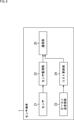
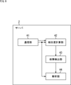
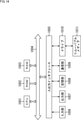
- FIG. 9 is a block diagram showing a configuration example of the server 2.
- the server 2 is composed of a communication unit 41, a coupling degree calculation unit 42, a failure detection unit 43, and an analysis unit 44.
- the communication unit 41 receives the sensor data transmitted from the sensor terminal 1 and outputs the sensor data to the coupling degree calculation unit 42 and the analysis unit 44. Further, the communication unit 41 receives the list of adjacent terminals transmitted from the sensor terminal 1 and outputs the list to the coupling degree calculation unit 42.
- the coupling degree calculation unit 42 obtains the sensor data coupling degree based on the correlation degree of the sensor data supplied from the communication unit 41. Further, the coupling degree calculation unit 42 obtains the beacon coupling degree based on the list of adjacent terminals supplied from the communication unit 41. The sensor data coupling degree and the beacon coupling degree obtained by the coupling degree calculation unit 42 are output to the failure detection unit 43.
- the failure detection unit 43 compares the sensor data coupling degree supplied from the coupling degree calculation unit 42 with the beacon coupling degree, and detects the failure of the sensor terminal 1 as described above based on the comparison result.
- the failure detection result by the failure detection unit 43 is output to the analysis unit 44.
- the analysis unit 44 analyzes the sensor data acquired by the sensor terminal 1 other than the failed sensor terminal 1 based on the failure detection result by the failure detection unit 43. That is, if there is sensor data measured by the sensor terminal 1 determined to be out of order, the analysis is performed so as to exclude it.
- step S1 the sensor 21 makes a measurement and acquires sensor data.
- step S2 the sensor monitoring unit 22 determines whether or not there is sensor data to be transmitted. For example, if there is a change in the sensor data acquired by the sensor 21, it is determined that there is sensor data to be transmitted.
- step S2 If it is determined in step S2 that there is sensor data to be transmitted, the communication unit 25 transmits the sensor data in step S3. After transmitting the sensor data, the process returns to step S1 and the subsequent processing is repeated.
- step S2 when it is determined in step S2 that there is no sensor data to be transmitted, the process returns to step S1 and the subsequent processing is repeated.
- the beacon transmission / reception processing of the sensor terminal 1 will be described with reference to the flowchart of FIG.
- the beacon transmission / reception process of FIG. 11 is performed in parallel with the sensor data transmission process described with reference to FIG. 10, for example.
- step S11 the beacon transmission / reception unit 23 determines whether or not the beacon transmission time has come, and waits until it is determined that the beacon transmission time has come.
- step S11 When it is determined in step S11 that the beacon transmission time has come, the beacon transmission / reception unit 23 transmits the beacon in step S12.
- step S13 the beacon transmission / reception unit 23 receives the beacon transmitted from the other sensor terminal 1.
- step S14 the list update unit 24 updates the adjacent terminal list based on the ID included in the beacon received by the beacon transmission / reception unit 23 and the information indicating the reception strength of the beacon.
- step S15 the list update unit 24 determines whether or not there has been a change in the beacon reception status.
- step S15 If it is determined in step S15 that the beacon reception status has changed, the communication unit 25 transmits the adjacent terminal list to the server 2 in step S16. After transmitting the adjacent terminal list, the process returns to step S1 and the subsequent processing is repeated.
- step S15 when it is determined in step S15 that there is no change in the beacon reception status, the process returns to step S1 and the subsequent processing is repeated.
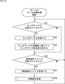
- step S31 the communication unit 41 determines whether or not the sensor data has been transmitted from the sensor terminal 1.
- step S32 the communication unit 41 receives the sensor data transmitted from the sensor terminal 1.
- step S33 the coupling degree calculation unit 42 obtains the sensor data coupling degree based on the correlation degree of the sensor data. After the sensor data coupling degree is obtained, the process proceeds to step S34. On the other hand, if it is determined in step S31 that the sensor data has not been transmitted, steps S32 and S33 are skipped.
- step S34 the communication unit 41 determines whether or not the adjacent terminal list has been transmitted from the sensor terminal 1.
- step S34 If it is determined in step S34 that the adjacent terminal list has been transmitted, the communication unit 41 receives the adjacent terminal list in step S35.
- step S36 the failure detection unit 43 performs a failure detection process.
- the failure detection process detects the failure of the sensor terminal 1. Details of the failure detection process will be described later with reference to FIG. After the failure detection process is performed, the process returns to step S31, and subsequent processes are performed.
- step S36 when it is determined in step S36 that the adjacent terminal list has not been transmitted, the process returns to step S31 and the subsequent processing is repeated.
- the analysis unit 44 of the server 2 analyzes the sensor data collected by the above data collection process.
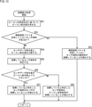
- step S36 of FIG. 12 The failure detection process performed in step S36 of FIG. 12 will be described with reference to the flowchart of FIG.
- step S51 the coupling degree calculation unit 42 obtains the beacon coupling degree based on the list of adjacent terminals representing the reception status of the beacon.
- step S52 the failure detection unit 43 determines whether or not there is a sensor terminal 1 in the adjacent sensor terminals 1 that does not transmit the adjacent terminal list.
- step S53 the failure detection unit 43 fails in the communication unit 25 of the sensor terminal 1 that does not transmit the adjacent terminal list. Detects that.
- the failure detection unit 43 compares the sensor data coupling degree and the beacon coupling degree in step S54.
- step S55 the failure detection unit 43 identifies the sensor terminal 1 included in any of the combinations having a large difference between the sensor data coupling degree and the beacon coupling degree as the failed sensor terminal 1.
- step S56 the failure detection unit 43 determines whether or not the sensor data coupling degree for the combination including the sensor terminal 1 that has identified the failure is smaller than the beacon coupling degree.
- the failure detection unit 43 detects in step S57 that the sensor 21 of the sensor terminal 1 identified as having a failure has failed. do.
- step S58 the failure detection unit 43 fails in the beacon transmission / reception unit 23 of the sensor terminal 1 identified as having a failure. Detects that.
- step S57 After it is detected in step S57 that the sensor 21 is out of order, or after it is detected in step S58 that the beacon transmission / reception unit 23 is out of order, the process returns to step S36 in FIG. Is done.
- the server 2 suppresses the processing load and power consumption, and based on the beacon coupling degree obtained based on the adjacent terminal list and the sensor data coupling degree obtained based on the sensor data. It is possible to efficiently detect the failed sensor terminal 1 and the failed portion of the sensor terminal 1.
- the failure detection process is performed at the timing when the adjacent terminal list is transmitted, but the failure detection process may be performed at the timing when the sensor data is transmitted.
- the failed sensor terminal 1 is identified by using the beacon coupling degree obtained in advance and the sensor data coupling degree obtained based on the newly transmitted sensor data. And so on.
- the above-mentioned series of processes can be executed by hardware or software.
- the programs constituting the software are installed from a program recording medium on a computer embedded in dedicated hardware, a general-purpose personal computer, or the like.
- FIG. 14 is a block diagram showing a configuration example of computer hardware that executes the above-mentioned series of processes programmatically.
- the CPU Central Processing Unit
- ROM Read Only Memory
- RAM Random Access Memory
- An input / output interface 1005 is further connected to the bus 1004.
- An input unit 1006 including a keyboard, a mouse, and the like, and an output unit 1007 including a display, a speaker, and the like are connected to the input / output interface 1005.
- the input / output interface 1005 is connected to a storage unit 1008 including a hard disk and a non-volatile memory, a communication unit 1009 including a network interface, and a drive 1010 for driving the removable media 1011.
- the CPU 1001 loads the program stored in the storage unit 1008 into the RAM 1003 via the input / output interface 1005 and the bus 1004 and executes the above-mentioned series of processes. Is done.
- the program executed by the CPU 1001 is recorded on the removable media 1011 or provided via a wired or wireless transmission medium such as a local area network, the Internet, or digital broadcasting, and is installed in the storage unit 1008.
- a wired or wireless transmission medium such as a local area network, the Internet, or digital broadcasting
- the program executed by the computer may be a program in which processing is performed in chronological order according to the order described in the present specification, in parallel, or at a necessary timing such as when a call is made. It may be a program in which processing is performed.
- the system means a set of a plurality of components (devices, modules (parts), etc.), and it does not matter whether all the components are in the same housing. Therefore, a plurality of devices housed in separate housings and connected via a network, and a device in which a plurality of modules are housed in one housing are both systems. ..
- this technology can take a cloud computing configuration in which one function is shared by multiple devices via a network and processed jointly.
- each step described in the above flowchart can be executed by one device or shared by a plurality of devices.
- An information processing apparatus including a detection unit that detects a failure of the terminal based on a comparison result with a second value representing a relationship between the terminals obtained based on the communication status between the terminals.
- the detection unit mounts the other terminal mounted on the failed terminal.
- the information processing apparatus according to (2) or (3) above, which detects that the communication unit used for communication with is out of order.
- Information processing equipment (6)
- the detection unit detects that the communication unit used for communication with the information processing apparatus mounted on the terminal that does not transmit information indicating the communication status between the terminals is out of order (5). ).
- the information processing device is provided to detects that the communication unit used for communication with the information processing apparatus mounted on the terminal that does not transmit information indicating the communication status between the terminals is out of order (5). ).
- the information processing device according to (5) or (6), wherein the receiving unit further receives the sensor data transmitted from the terminal in response to a change in the sensor data.
- the information indicating the communication status between the terminals represents the status of communication with other terminals using a radio wave weaker than the radio wave used for transmitting the sensor data in the terminal (5).
- the information processing apparatus according to any one of (7).
- the information processing device according to (8) above, wherein the communication performed between the terminal and another terminal is performed by transmitting and receiving a beacon containing information that can identify the terminal.
- the information representing the communication status between the terminals includes information included in the beacon transmitted from another terminal and information representing the reception strength of the beacon.
- the information processing apparatus (11) The information processing apparatus according to (10), wherein the second value is obtained as a value proportional to the reception intensity of the beacon. (12)
- the first value is a value proportional to the degree of correlation between the sensor data acquired by the sensor mounted on the terminal and the sensor data acquired by the sensor mounted on another terminal.
- the information processing apparatus according to any one of (1) to (11).
- the information processing apparatus according to any one of (2) to (12), further comprising an analysis unit that analyzes the sensor data acquired by the terminal other than the failed terminal.
- Information processing equipment The first value representing the relationship between the terminals obtained based on the sensor data acquired by the sensors mounted on each of the plurality of terminals that communicate with each other with other terminals, and the terminal.
- An information processing method for detecting a failure of the terminal based on a comparison result with a second value representing a relationship between the terminals obtained based on the communication status between the terminals With the sensor The first communication unit that communicates with other terminals, A plurality of terminals including a second communication unit that transmits sensor data acquired by the sensor and information indicating a communication status with the other terminal. The first value representing the relationship between the terminals obtained based on the sensor data transmitted from each of the terminals and the relationship between the terminals obtained based on the communication status between the terminals.
- An information processing system configured to include an information processing apparatus including a detection unit for detecting a failure of the terminal based on a comparison result with a second value representing.
Landscapes
- Engineering & Computer Science (AREA)
- Computer Networks & Wireless Communication (AREA)
- Signal Processing (AREA)
- Physics & Mathematics (AREA)
- Electromagnetism (AREA)
- Quality & Reliability (AREA)
- General Physics & Mathematics (AREA)
- Emergency Management (AREA)
- Business, Economics & Management (AREA)
- Algebra (AREA)
- Mathematical Analysis (AREA)
- Mathematical Optimization (AREA)
- Mathematical Physics (AREA)
- Probability & Statistics with Applications (AREA)
- Pure & Applied Mathematics (AREA)
- Arrangements For Transmission Of Measured Signals (AREA)
- Mobile Radio Communication Systems (AREA)
Abstract
Description
本技術は、情報処理装置、情報処理方法、および情報処理システムに関し、特に、センサ端末の故障を効率的に検出することができるようにした情報処理装置、情報処理方法、および情報処理システムに関する。 The present technology relates to an information processing device, an information processing method, and an information processing system, and more particularly to an information processing device, an information processing method, and an information processing system capable of efficiently detecting a failure of a sensor terminal.
インターネットに接続した多数のセンサ端末から情報を収集し、環境の変化を把握するIoT(Internet of Things)のシステムがある。このようなシステムでは、多数のセンサ端末が広範囲に存在するため、センサ端末の故障を人が介在することなく検出する仕組みが要求される。 There is an IoT (Internet of Things) system that collects information from a large number of sensor terminals connected to the Internet and grasps changes in the environment. In such a system, since a large number of sensor terminals exist in a wide range, a mechanism for detecting a failure of the sensor terminals without human intervention is required.
また、故障を検出する仕組みを、センサ端末の消費電力を上げることなく、かつ、サーバ側の処理負荷と通信負荷を上げることなく、実現することが要求される。 In addition, it is required to realize a mechanism for detecting a failure without increasing the power consumption of the sensor terminal and without increasing the processing load and communication load on the server side.
例えば、特許文献1には、通信に関連する情報を各センサ機器から周期的に取得する故障検出装置において、通信に関連する情報の統計的な変化に基づいて故障を検出する仕組みが記載されている。 For example, Patent Document 1 describes a mechanism for detecting a failure based on a statistical change in information related to communication in a failure detection device that periodically acquires information related to communication from each sensor device. There is.
特許文献1に記載の技術において、故障検出装置としてのサーバに対して情報を周期的に送信することは、センサ端末の消費電力の点からは望ましくない。また、センサ端末から情報が周期的に送信されてくることは、サーバの処理負荷や通信負荷の点からも望ましくない。 In the technique described in Patent Document 1, it is not desirable from the viewpoint of power consumption of the sensor terminal to periodically transmit information to the server as a failure detection device. Further, it is not desirable from the viewpoint of the processing load and communication load of the server that the information is periodically transmitted from the sensor terminal.
IoTのシステムにおいて一般的に用いられるMQTT(Message Queueing Telemetry Transport)プロトコル通信では、センサ端末がサーバに対してKeep Aliveパケットを周期的に送信するようになっている。サーバにおいては、Keep Aliveパケットを受信することにより、センサ端末が故障していないことが確認され、TCPセッションが保持される。MQTTプロトコル通信を用いる場合でも、センサ端末の消費電力が大きくなるとともに、サーバの処理負荷や通信負荷が高くなる。 In MQTT (Message Queueing Telemetry Transport) protocol communication, which is generally used in IoT systems, the sensor terminal periodically sends Keep Alive packets to the server. By receiving the KeepAlive packet on the server, it is confirmed that the sensor terminal has not failed, and the TCP session is maintained. Even when MQTT protocol communication is used, the power consumption of the sensor terminal increases, and the processing load and communication load of the server also increase.
本技術はこのような状況に鑑みてなされたものであり、センサ端末の故障を効率的に検出することができるようにするものである。 This technology was made in view of such a situation, and makes it possible to efficiently detect the failure of the sensor terminal.
本技術の一側面の情報処理装置は、他の端末との間で相互に通信を行う複数の端末のそれぞれに搭載されたセンサにより取得されたセンサデータに基づいて求められた前記端末間の関係性を表す第1の値と、前記端末間の通信状況に基づいて求められた前記端末間の関係性を表す第2の値との比較結果に基づいて、前記端末の故障を検出する検出部を備える。 The information processing device of one aspect of the present technology is a relationship between the terminals obtained based on sensor data acquired by sensors mounted on each of a plurality of terminals that communicate with each other with other terminals. A detection unit that detects a failure of the terminal based on a comparison result between a first value representing the sex and a second value representing the relationship between the terminals obtained based on the communication status between the terminals. To prepare for.
本技術の他の側面の情報処理システムは、センサと、他の端末と相互に通信を行う第1の通信部と、前記センサにより取得されたセンサデータと、前記他の端末との通信状況を表す情報とを送信する第2の通信部とを備える複数の端末と、それぞれの前記端末から送信されてきた、前記センサデータに基づいて求められた前記端末間の関係性を表す第1の値と、前記端末間の通信状況に基づいて求められた前記端末間の関係性を表す第2の値との比較結果に基づいて、前記端末の故障を検出する検出部を備える情報処理装置とを含むように構成される。 The information processing system of the other aspect of the present technology determines the communication status between the sensor, the first communication unit that communicates with the other terminal, the sensor data acquired by the sensor, and the other terminal. A first value representing a relationship between a plurality of terminals including a second communication unit for transmitting information to be represented and the terminal obtained based on the sensor data transmitted from each terminal. And an information processing device including a detection unit that detects a failure of the terminal based on a comparison result with a second value representing the relationship between the terminals obtained based on the communication status between the terminals. It is configured to include.
本技術においては、他の端末との間で相互に通信を行う複数の端末のそれぞれに搭載されたセンサにより取得されたセンサデータに基づいて求められた前記端末間の関係性を表す第1の値と、前記端末間の通信状況に基づいて求められた前記端末間の関係性を表す第2の値との比較結果に基づいて、前記端末の故障が検出される。 In the present technology, the first aspect representing the relationship between the terminals obtained based on the sensor data acquired by the sensors mounted on each of the plurality of terminals that communicate with each other with other terminals. A failure of the terminal is detected based on a comparison result between the value and a second value representing the relationship between the terminals obtained based on the communication status between the terminals.
以下、本技術を実施するための形態について説明する。説明は以下の順序で行う。
1.情報処理システムの概要
2.各機器の構成
3.各機器の動作
4.その他
Hereinafter, a mode for implementing the present technology will be described. The explanation will be given in the following order.
1. 1. Overview of
<1.情報処理システムの概要>
図1は、本技術の一実施形態に係る情報処理システムの構成例を示す図である。
<1. Information processing system overview>
FIG. 1 is a diagram showing a configuration example of an information processing system according to an embodiment of the present technology.
図1の情報処理システムは、例えば、広範囲に配置された複数のセンサ端末により取得された情報に基づいて、それぞれの設置場所の温度や湿度などの分布の時系列変化を把握し、AI(Artificial Intelligence)を用いてビッグデータ解析を行うシステムである。ビッグデータ解析により得られた情報は、農業などの分野の様々な予測に活用される。 For example, the information processing system of FIG. 1 grasps time-series changes in the distribution of temperature, humidity, etc. at each installation location based on information acquired by a plurality of sensor terminals arranged over a wide area, and AI (Artificial). It is a system that performs big data analysis using Intelligence). The information obtained by big data analysis will be used for various forecasts in fields such as agriculture.
情報処理システムは、センサ端末1A乃至1Cが、インターネットなどのネットワーク3を介してサーバ2に接続されることにより構成される。例えば、センサ端末1A乃至1Cは、5GmMTC(5G massive Machine Type Communication)通信などの移動体通信を用いてサーバ2と接続される。
The information processing system is configured by connecting
センサ端末1A乃至1Cは、1つまたは複数のセンサを備えるいわゆるIoTデバイスである。センサ端末1A乃至1Cは、カメラ、マイクロフォン、温度センサ、湿度センサ、振動センサ、光センサ、気圧センサなどの周囲の環境をセンシングするセンサのうち、少なくとも1つのセンサを備える。
センサ端末1A乃至1Cは、測定対象の測定を行い、送信すべき測定結果がある場合、測定結果を表すセンサデータをサーバ2に送信する。送信すべき測定結果がある場合にだけ、センサデータの送信が不定期で行われるようにすることにより、センサデータの送信頻度を抑え、センサ端末1A乃至1Cの消費電力を低下させることが可能となる。
The
また、図1の破線矢印で示すように、センサ端末1A乃至1Cは、例えば10分間隔でビーコンの送受信を行う。ビーコンの送受信は、微弱電波を用いた近距離の無線通信により行われる。
Further, as shown by the broken line arrow in FIG. 1, the
センサ端末1A乃至1Cは、隣接しているセンサ端末の存在を、ビーコンを受信することによって把握し、隣接しているセンサ端末との通信状況を表す情報をサーバ2に送信する。ビーコンの送受信を行うことができるセンサ端末、言い換えると、ビーコンの送受信に用いられる微弱電波の到達範囲内にあるセンサ端末が、隣接しているセンサ端末となる。
The
なお、図1には3台のセンサ端末が示されているが、実際には、さらに多くのセンサ端末が設けられる。以下、適宜、センサ端末1A乃至1Cをそれぞれ区別する必要がない場合、まとめてセンサ端末1と称する。
Although three sensor terminals are shown in FIG. 1, more sensor terminals are actually provided. Hereinafter, when it is not necessary to distinguish the
サーバ2は、コンピュータにより構成される情報処理装置である。サーバ2は、センサ端末1から送信されてきたセンサデータを受信し、解析を行う。
The
送信すべきセンサデータがある場合にだけ、センサデータが送信されてくるため、サーバ2は、センサ端末1からセンサデータが送信されてこない状況が、送信すべきセンサデータがない状況であるのか、または、センサ端末1が故障している状況であるのかを判別する必要がある。そのため、サーバ2は、以下のようにして、ビーコンの受信状況とセンサデータに基づいて、センサ端末1の故障を検出する。
Since the sensor data is transmitted only when there is sensor data to be transmitted, the
図2は、センサ端末1が送信する情報の例を示す図である。 FIG. 2 is a diagram showing an example of information transmitted by the sensor terminal 1.
上述したように、センサ端末1A乃至1Cは、微弱電波を用いてビーコンの送受信を定期的に行う。ビーコンには、センサ端末1A乃至1Cのそれぞれに割り振られたIDなどの、センサ端末1A乃至1Cを特定可能な情報が含まれる。
As described above, the
センサ端末1は、他のセンサ端末1から送信されてきたビーコンを受信し、隣接端末リストを保持する。隣接端末リストは、センサ端末1により受信されたビーコンに含まれるID(ビーコンの送信元のセンサ端末1のID)と、当該ビーコンの受信強度を表す情報とを対応付けた情報である。図2の例においては、センサ端末1A乃至1CのそれぞれにAAAA,BBBB,CCCCのIDが割り当てられている。
The sensor terminal 1 receives a beacon transmitted from another sensor terminal 1 and holds a list of adjacent terminals. The adjacent terminal list is information in which an ID included in the beacon received by the sensor terminal 1 (ID of the sensor terminal 1 that is the transmission source of the beacon) and information indicating the reception strength of the beacon are associated with each other. In the example of FIG. 2, AAAA, BBBB, and CCCC IDs are assigned to the
例えば、センサ端末1Aは、センサ端末1Bとセンサ端末1Cから送信されてきたビーコンを受信し、隣接端末リストL1を保持する。隣接端末リストL1には、センサ端末1Bとの通信状況を表す情報として、センサ端末1Bから送信されてきたビーコンの受信強度が-40であることが記録される。また、隣接端末リストL1には、センサ端末1Cとの通信状況を表す情報として、センサ端末1Cから送信されてきたビーコンの受信強度が-60であることが記録される。
For example, the
同様に、センサ端末1Bは、センサ端末1Aとセンサ端末1Cから送信されてきたビーコンを受信し、隣接端末リストL2を保持する。隣接端末リストL2には、センサ端末1Aとの通信状況を表す情報と、センサ端末1Cとの通信状況を表す情報がそれぞれ記録される。
Similarly, the
センサ端末1Cは、センサ端末1Aとセンサ端末1Bから送信されてきたビーコンを受信し、隣接端末リストL3を保持する。隣接端末リストL3には、センサ端末1Aとの通信状況を表す情報と、センサ端末1Bとの通信状況を表す情報がそれぞれ記録される。
The
センサ端末1A乃至1Cは、他のセンサ端末1との通信状況が変化した場合、それぞれが保持する隣接端末リストL1乃至L3をサーバ2に送信する。
When the communication status with the other sensor terminals 1 changes, the
サーバ2は、センサ端末1A乃至1Cから送信されてきた隣接端末リストL1乃至L3を受信し、隣接端末リストL1乃至L3に基づいてビーコン結合度を求める。また、サーバ2は、センサ端末1A乃至1Cから送信されてきたセンサデータに基づいてセンサデータ結合度を求める。
The
ビーコン結合度は、隣接端末リストに基づいて、すなわち、ビーコンの送受信の状況に基づいて求められた、センサ端末1間の関係性を表す値である。センサデータ結合度は、センサデータに基づいて求められた、センサ端末1間の関係性を表す値である。 The beacon coupling degree is a value representing the relationship between the sensor terminals 1 obtained based on the list of adjacent terminals, that is, based on the transmission / reception status of the beacon. The sensor data coupling degree is a value representing the relationship between the sensor terminals 1 obtained based on the sensor data.
図3は、2種類の結合度について示す図である。 FIG. 3 is a diagram showing two types of coupling.
図3の上段に示すように、センサ端末1A乃至1Cから送信されてきた隣接端末リストL1乃至L3に基づいて、3つのビーコン結合度が求められる。例えば、ビーコン結合度は、センサ端末1間のビーコンの受信強度に比例する値として求められる。
As shown in the upper part of FIG. 3, three beacon coupling degrees are obtained based on the adjacent terminal lists L1 to L3 transmitted from the
図3に示すビーコン結合度VbA-B、VbA-C、VbB-Cは、それぞれ、センサ端末1Aとセンサ端末1Bの間のビーコン結合度、センサ端末1Aとセンサ端末1Cの間のビーコン結合度、センサ端末1Bとセンサ端末1Cの間のビーコン結合度である。
Beacon coupling degree Vb A-B shown in FIG. 3, Vb A-C, Vb B-C , respectively, the beacon degree of coupling between the
また、図3の下段に示すように、センサ端末1A乃至1Cから送信されてきたセンサデータD1乃至D3に基づいて、3つのセンサデータ結合度が求められる。センサデータD1乃至D3は、それぞれセンサ端末1A乃至1Cにより取得されたセンサデータである。
Further, as shown in the lower part of FIG. 3, three sensor data coupling degrees are obtained based on the sensor data D1 to D3 transmitted from the
隣接しているセンサ端末1は近くの環境を測定しているため、隣接しているセンサ端末1により取得されたセンサデータは相関が大きくなると考えられる。サーバ2は、それぞれのセンサ端末1から送信されてきたセンサデータ間の相関度を計算し、相関度に比例する値としてセンサデータ結合度を求める。
Since the adjacent sensor terminal 1 measures the nearby environment, it is considered that the sensor data acquired by the adjacent sensor terminal 1 has a large correlation. The
図3に示すセンサデータ結合度VsA-B、VsA-C、VsB-Cは、センサ端末1Aとセンサ端末1Bの間のセンサデータ結合度、センサ端末1Aとセンサ端末1Cの間のセンサデータ結合度、センサ端末1Bとセンサ端末1Cの間のセンサデータ結合度である。
Sensor data coupling degree Vs A-B shown in FIG. 3, Vs A-C, Vs B-C , the sensor data the degree of coupling between the
サーバ2は、センサ端末1の組み合わせのそれぞれに対して求めたビーコン結合度とセンサデータ結合度を比較する。
The
図4は、ビーコン結合度とセンサデータ結合度の比較の例を示す図である。 FIG. 4 is a diagram showing an example of comparison between the beacon coupling degree and the sensor data coupling degree.
図4に示すように、センサ端末1Aとセンサ端末1Bの関係性を表すビーコン結合度VbA-Bとセンサデータ結合度VsA-Bが比較され、センサ端末1Aとセンサ端末1Cの関係性を表すビーコン結合度VbA-Cとセンサデータ結合度VsA-Cが比較される。また、センサ端末1Bとセンサ端末1Cの関係性を表すビーコン結合度VbA-Cとセンサデータ結合度VsB-Cが比較される。
As shown in FIG. 4, the beacon coupling degree represents the relationship between the
サーバ2は、ビーコン結合度とセンサデータ結合度の相違の大きさに基づいて、故障しているセンサ端末1を特定する。
The
図5は、故障しているセンサ端末1の特定の例を示す図である。 FIG. 5 is a diagram showing a specific example of the sensor terminal 1 that is out of order.
図5の例では、ビーコン結合度VbA-Bとセンサデータ結合度VsA-Bの相違が小さく、ビーコン結合度VbA-Cとセンサデータ結合度VsA-Cの相違が大きい。ビーコン結合度VbB-Cとセンサデータ結合度VsB-Cの相違も大きい。相違の大小は、例えば、あらかじめ設定された閾値を基準として判断される。 In the example of FIG. 5, the beacon binding of Vb A-B and the sensor data coupling degree Vs difference A-B is small, a large difference in the beacon coupling degree Vb A-C sensor data coupling degree Vs A-C. Differences beacon binding of Vb B-C and the sensor data coupling degree Vs B-C is also large. The magnitude of the difference is determined based on, for example, a preset threshold value.
サーバ2は、2種類の結合度の相違が大きい組み合わせに含まれるセンサ端末1のうち、いずれかのセンサ端末1が故障していると判断する。図5の例では、センサ端末1Aとセンサ端末1Cの関係性を表すビーコン結合度VbA-Cとセンサデータ結合度VsA-Cの相違が大きく、センサ端末1Bとセンサ端末1Cの関係性を表すビーコン結合度VbB-Cとセンサデータ結合度VsB-Cの相違が大きい。サーバ2は、いずれの組み合わせにも含まれるセンサ端末1Cが、故障しているセンサ端末1であるとして特定する。
The
サーバ2は、故障しているセンサ端末1がセンサ端末1Cであるとして特定した後、ビーコン結合度とセンサデータ結合度の比較結果に基づいて、故障していると特定したセンサ端末1Cの故障箇所をさらに特定する。
The
図6は、故障箇所の特定の例を示す図である。 FIG. 6 is a diagram showing a specific example of a failure location.
センサが正常に動作している場合、ビーコン結合度と同程度のセンサデータ結合度が、センサデータの相関性に基づいて求められると考えられる。このため、図6の上段に示すように、例えば、故障していると特定したセンサ端末1Cを含む組み合わせのセンサデータ結合度VsA-Cが、ビーコン結合度VbA-Cよりも小さい場合、サーバ2は、センサ端末1Cに搭載されたセンサが故障していると判断する。
When the sensor is operating normally, it is considered that the sensor data coupling degree to the same extent as the beacon coupling degree is obtained based on the correlation of the sensor data. Thus, if as shown in the upper part of FIG. 6, for example, sensor data coupling degree Vs A-C combination including a
また、ビーコンの送受信が正常に行われている場合、センサデータ結合度と同程度のビーコン結合度が、ビーコンの受信状況に基づいて求められると考えられる。このため、図6の下段に示すように、例えば、ビーコン結合度VbA-Cが、センサデータ結合度VsA-Cよりも小さい場合、サーバ2は、センサ端末1Cに搭載されたビーコンの送受信部が故障していると判断する。
Further, when the transmission / reception of the beacon is normally performed, it is considered that the degree of beacon coupling to the same degree as the sensor data coupling degree is obtained based on the reception status of the beacon. Therefore, as shown in the lower part of FIG. 6, for example, a beacon coupling degree Vb A-C is smaller than the sensor data coupling degree Vs A-C, the
サーバ2は、ビーコン結合度とセンサデータ結合度との比較結果だけではなく、隣接端末リストが送信されてきたか否かに基づいて、センサ端末1の故障箇所を特定する。
The
図7は、隣接端末リストが送信されてきたか否かに基づく故障箇所の特定の例を示す図である。 FIG. 7 is a diagram showing a specific example of a failure location based on whether or not an adjacent terminal list has been transmitted.
センサ端末1A乃至1Cが上述したように隣接している場合、ビーコンの受信状況が変化したことに応じて、センサ端末1A乃至1Cのそれぞれから隣接端末リストが送信されることになる。
When the
それにも関わらず、図7に示すように、センサ端末1Aとセンサ端末1Bからだけ隣接端末リストが送信され、センサ端末1Cからは隣接端末リストが送信されない場合、サーバ2は、隣接端末リストを送信してこないセンサ端末1Cに搭載された、サーバ2との通信を行う通信部が故障していると判断する。
Nevertheless, as shown in FIG. 7, when the adjacent terminal list is transmitted only from the
以上のように、サーバ2においては、ビーコンの受信状況に変化があった場合にセンサ端末1から送信されてきた隣接端末リストに基づいて求められたビーコン結合度と、送信すべきセンサデータがある場合にセンサ端末1から送信されてきたセンサデータに基づいて求められたセンサデータ結合度との比較結果に基づいて、センサ端末1の故障箇所を検出する処理が行われる。
As described above, the
センサ端末1において定期的に行われる通信は、微弱電波を用いたビーコンの送受信だけであるため、センサ端末1の消費電力を低減させることが可能となる。 Since the communication performed periodically in the sensor terminal 1 is only the transmission / reception of a beacon using a weak radio wave, it is possible to reduce the power consumption of the sensor terminal 1.
また、ビーコンの受信状況に変化があった場合にだけ、隣接端末リストがサーバ2に対して送信され、故障箇所を検出する処理が行われるため、サーバ2は、故障箇所を検出する処理に必要となる処理負荷や通信負荷を低減させることが可能となる。すなわち、サーバ2は、センサ端末1の故障を効率的に検出することが可能となる。
Further, only when the reception status of the beacon changes, the adjacent terminal list is transmitted to the
<2.各機器の構成>
・センサ端末の構成
図8は、センサ端末1の構成例を示すブロック図である。
<2. Configuration of each device>
Configuration of the sensor terminal FIG. 8 is a block diagram showing a configuration example of the sensor terminal 1.
図8に示すように、センサ端末1は、センサ21、センサ監視部22、ビーコン送受信部23、リスト更新部24、および通信部25により構成される。
As shown in FIG. 8, the sensor terminal 1 is composed of a
センサ21は、上述したセンサにより構成される。センサ21は、例えば所定の周期で対象を測定し、測定結果を表すセンサデータをセンサ監視部22に出力する。
The
センサ監視部22は、センサ21から供給されたセンサデータを監視する。センサ監視部22は、送信すべきセンサデータがある場合、センサデータを通信部25に出力し、サーバ2に対して送信させる。
The
ビーコン送受信部23は、サーバ2との通信に用いられる電波よりも弱い微弱電波を用いて、他のセンサ端末1との間でビーコンの送受信を行う。例えば、ビーコン送受信部23は、Bluetooth(登録商標)などの近距離無線通信を用いてビーコンを定期的に送信する。
The beacon transmission /
また、ビーコン送受信部23は、他のセンサ端末1から送信されてきたビーコンを受信し、ビーコンに含まれるIDと、ビーコンの受信強度を表す情報とをリスト更新部24に出力する。
Further, the beacon transmission /
リスト更新部24は、ビーコン送受信部23から供給された情報に基づいて、隣接端末リストを更新する。リスト更新部24は、ビーコンを元々受信できていたセンサ端末1からビーコンを受信できなかった場合などのように、ビーコンの受信状況に変化があった場合、隣接端末リストを通信部25に出力し、サーバ2に対して送信させる。
The
通信部25は、5GmMTC通信などの移動体無線通信によりサーバ2と通信を行う。通信部25は、センサ監視部22から供給されたセンサデータと、リスト更新部24から供給された隣接端末リストをサーバ2に対して送信する。
The
・サーバの構成
図9は、サーバ2の構成例を示すブロック図である。
-Server configuration FIG. 9 is a block diagram showing a configuration example of the
図9に示すように、サーバ2は、通信部41、結合度計算部42、故障検出部43、および解析部44により構成される。
As shown in FIG. 9, the
通信部41は、センサ端末1から送信されてきたセンサデータを受信し、結合度計算部42と解析部44に出力する。また、通信部41は、センサ端末1から送信されてきた隣接端末リストを受信し、結合度計算部42に出力する。
The
結合度計算部42は、通信部41から供給されたセンサデータの相関度に基づいてセンサデータ結合度を求める。また、結合度計算部42は、通信部41から供給された隣接端末リストに基づいてビーコン結合度を求める。結合度計算部42により求められたセンサデータ結合度とビーコン結合度は、故障検出部43に出力される。
The coupling
故障検出部43は、結合度計算部42から供給されたセンサデータ結合度とビーコン結合度とを比較し、その比較結果に基づいて、上述したようにしてセンサ端末1の故障を検出する。故障検出部43による故障の検出結果は解析部44に出力される。
The
解析部44は、故障検出部43による故障の検出結果に基づいて、故障しているセンサ端末1以外のセンサ端末1により取得されたセンサデータの解析を行う。すなわち、故障していると判断されたセンサ端末1により計測されたセンサデータがある場合、それを除くようにして解析が行われる。
The
<3.各機器の動作>
ここで、以上のような構成を有する各機器の動作について説明する。
<3. Operation of each device>
Here, the operation of each device having the above configuration will be described.
・センサ端末の動作
図10のフローチャートを参照して、センサ端末1のセンサデータ送信処理について説明する。
-Operation of the sensor terminal The sensor data transmission process of the sensor terminal 1 will be described with reference to the flowchart of FIG.
ステップS1において、センサ21は測定を行い、センサデータを取得する。
In step S1, the
ステップS2において、センサ監視部22は、送信すべきセンサデータがあるか否かを判定する。例えば、センサ21により取得されたセンサデータに変化があった場合、送信すべきセンサデータがあると判定される。
In step S2, the
送信すべきセンサデータがあるとステップS2において判定された場合、ステップS3において、通信部25は、センサデータを送信する。センサデータの送信後、ステップS1に戻り、それ以降の処理が繰り返し行われる。
If it is determined in step S2 that there is sensor data to be transmitted, the
送信すべきセンサデータがないとステップS2において判定された場合も同様に、ステップS1に戻り、それ以降の処理が繰り返し行われる。 Similarly, when it is determined in step S2 that there is no sensor data to be transmitted, the process returns to step S1 and the subsequent processing is repeated.
次に、図11のフローチャートを参照して、センサ端末1のビーコン送受信処理について説明する。図11のビーコン送受信処理は、例えば、図10を参照して説明したセンサデータ送信処理と並行して行われる。 Next, the beacon transmission / reception processing of the sensor terminal 1 will be described with reference to the flowchart of FIG. The beacon transmission / reception process of FIG. 11 is performed in parallel with the sensor data transmission process described with reference to FIG. 10, for example.
ステップS11において、ビーコン送受信部23は、ビーコンの送信時刻になったか否かを判定し、ビーコンの送信時刻になったと判定するまで待機する。
In step S11, the beacon transmission /
ビーコンの送信時刻になったとステップS11において判定した場合、ステップS12において、ビーコン送受信部23は、ビーコンを送信する。
When it is determined in step S11 that the beacon transmission time has come, the beacon transmission /
ステップS13において、ビーコン送受信部23は、他のセンサ端末1から送信されてきたビーコンを受信する。
In step S13, the beacon transmission /
ステップS14において、リスト更新部24は、ビーコン送受信部23により受信されたビーコンに含まれるIDと、ビーコンの受信強度を表す情報とに基づいて、隣接端末リストを更新する。
In step S14, the
ステップS15において、リスト更新部24は、ビーコンの受信状況に変化があったか否かを判定する。
In step S15, the
ビーコンの受信状況に変化があったとステップS15において判定された場合、ステップS16において、通信部25は、隣接端末リストをサーバ2に送信する。隣接端末リストの送信後、ステップS1に戻り、それ以降の処理が繰り返し行われる。
If it is determined in step S15 that the beacon reception status has changed, the
ビーコンの受信状況に変化がないとステップS15において判定された場合も同様に、ステップS1に戻り、それ以降の処理が繰り返し行われる。 Similarly, when it is determined in step S15 that there is no change in the beacon reception status, the process returns to step S1 and the subsequent processing is repeated.
・サーバの動作
図12のフローチャートを参照して、サーバ2のデータ収集処理について説明する。サーバ2においては、図12の処理の開始前に送信されてきた隣接端末リストなどに基づいて、どのセンサ端末1が互いに隣接しているのかが特定されているものとする。
-Server operation The data collection process of the
ステップS31において、通信部41は、センサデータがセンサ端末1から送信されてきたか否かを判定する。
In step S31, the
センサデータが送信されてきたとステップS31において判定した場合、ステップS32において、通信部41は、センサ端末1から送信されてきたセンサデータを受信する。
When it is determined in step S31 that the sensor data has been transmitted, in step S32, the
ステップS33において、結合度計算部42は、センサデータの相関度に基づいてセンサデータ結合度を求める。センサデータ結合度が求められた後、処理はステップS34に進む。一方、センサデータが送信されてきていないとステップS31において判定された場合、ステップS32,S33がスキップされる。
In step S33, the coupling
ステップS34において、通信部41は、隣接端末リストがセンサ端末1から送信されてきたか否かを判定する。
In step S34, the
隣接端末リストが送信されてきたとステップS34において判定した場合、ステップS35において、通信部41は、隣接端末リストを受信する。
If it is determined in step S34 that the adjacent terminal list has been transmitted, the
ステップS36において、故障検出部43は故障検出処理を行う。故障検出処理により、センサ端末1の故障が検出される。故障検出処理の詳細については、図13を参照して後述する。故障検出処理が行われた後、ステップS31に戻り、それ以降の処理が行われる。
In step S36, the
一方、隣接端末リストが送信されてきていないとステップS36において判定された場合も同様に、ステップS31に戻り、それ以降の処理が繰り返し行われる。 On the other hand, when it is determined in step S36 that the adjacent terminal list has not been transmitted, the process returns to step S31 and the subsequent processing is repeated.
サーバ2の解析部44においては、以上のようなデータ収集処理により収集されたセンサデータが解析される。
The
図13のフローチャートを参照して、図12のステップS36において行われる故障検出処理について説明する。 The failure detection process performed in step S36 of FIG. 12 will be described with reference to the flowchart of FIG.
ステップS51において、結合度計算部42は、ビーコンの受信状況を表す隣接端末リストに基づいてビーコン結合度を求める。
In step S51, the coupling
ステップS52において、故障検出部43は、隣接するセンサ端末1の中に、隣接端末リストを送信してこないセンサ端末1があるか否かを判定する。
In step S52, the
隣接端末リストを送信してこないセンサ端末1があるとステップS52において判定した場合、ステップS53において、故障検出部43は、隣接端末リストを送信してこないセンサ端末1の通信部25が故障していることを検出する。
When it is determined in step S52 that there is a sensor terminal 1 that does not transmit the adjacent terminal list, in step S53, the
隣接端末リストを送信してこないセンサ端末1の通信部25が故障していることが検出された後、図12のステップS36に戻り、それ以降の処理が行われる。
After it is detected that the
一方、隣接端末リストを送信してこないセンサ端末1がないとステップS52において判定した場合、ステップS54において、故障検出部43は、センサデータ結合度とビーコン結合度を比較する。
On the other hand, when it is determined in step S52 that there is no sensor terminal 1 that does not transmit the adjacent terminal list, the
ステップS55において、故障検出部43は、センサデータ結合度とビーコン結合度の相違が大きい組み合わせのいずれにも含まれるセンサ端末1を、故障しているセンサ端末1として特定する。
In step S55, the
ステップS56において、故障検出部43は、故障していることを特定したセンサ端末1を含む組み合わせに関するセンサデータ結合度が、ビーコン結合度よりも小さいか否かを判定する。
In step S56, the
センサデータ結合度がビーコン結合度よりも小さいとステップS56において判定した場合、ステップS57において、故障検出部43は、故障していると特定したセンサ端末1のセンサ21が故障していることを検出する。
When it is determined in step S56 that the sensor data coupling degree is smaller than the beacon coupling degree, the
一方、センサデータ結合度がビーコン結合度よりも大きいとステップS56において判定した場合、ステップS58において、故障検出部43は、故障していると特定したセンサ端末1のビーコン送受信部23が故障していることを検出する。
On the other hand, when it is determined in step S56 that the sensor data coupling degree is larger than the beacon coupling degree, in step S58, the
ステップS57でセンサ21が故障していることが検出された後、または、ステップS58でビーコン送受信部23が故障していることが検出された後、図12のステップS36に戻り、それ以降の処理が行われる。
After it is detected in step S57 that the
以上のように、サーバ2は、処理の負荷や消費電力を抑えつつ、隣接端末リストに基づいて求められたビーコン結合度と、センサデータに基づいて求められたセンサデータ結合度とに基づいて、故障しているセンサ端末1と、そのセンサ端末1の故障箇所とを効率的に検出することができる。
As described above, the
<4.その他>
以上においては、隣接端末リストが送信されてきたタイミングで故障検出処理が行われるものとしたが、センサデータが送信されてきたタイミングでも故障検出処理が行われるようにしてもよい。この場合、サーバ2においては、あらかじめ求められているビーコン結合度と、新たに送信されてきたセンサデータに基づいて求められたセンサデータ結合度とを用いて、故障しているセンサ端末1の特定などが行われる。
<4. Others>
In the above, it is assumed that the failure detection process is performed at the timing when the adjacent terminal list is transmitted, but the failure detection process may be performed at the timing when the sensor data is transmitted. In this case, in the
・コンピュータについて
上述した一連の処理は、ハードウェアにより実行することもできるし、ソフトウェアにより実行することもできる。一連の処理をソフトウェアにより実行する場合には、そのソフトウェアを構成するプログラムが、専用のハードウェアに組み込まれているコンピュータ、または汎用のパーソナルコンピュータなどに、プログラム記録媒体からインストールされる。
-Computer The above-mentioned series of processes can be executed by hardware or software. When a series of processes are executed by software, the programs constituting the software are installed from a program recording medium on a computer embedded in dedicated hardware, a general-purpose personal computer, or the like.
図14は、上述した一連の処理をプログラムにより実行するコンピュータのハードウェアの構成例を示すブロック図である。 FIG. 14 is a block diagram showing a configuration example of computer hardware that executes the above-mentioned series of processes programmatically.
CPU(Central Processing Unit)1001、ROM(Read Only Memory)1002、RAM(Random Access Memory)1003は、バス1004により相互に接続されている。
The CPU (Central Processing Unit) 1001, the ROM (Read Only Memory) 1002, and the RAM (Random Access Memory) 1003 are connected to each other by the
バス1004には、さらに、入出力インタフェース1005が接続されている。入出力インタフェース1005には、キーボード、マウスなどよりなる入力部1006、ディスプレイ、スピーカなどよりなる出力部1007が接続される。また、入出力インタフェース1005には、ハードディスクや不揮発性のメモリなどよりなる記憶部1008、ネットワークインタフェースなどよりなる通信部1009、リムーバブルメディア1011を駆動するドライブ1010が接続される。
An input /
以上のように構成されるコンピュータでは、CPU1001が、例えば、記憶部1008に記憶されているプログラムを入出力インタフェース1005及びバス1004を介してRAM1003にロードして実行することにより、上述した一連の処理が行われる。
In the computer configured as described above, the
CPU1001が実行するプログラムは、例えばリムーバブルメディア1011に記録して、あるいは、ローカルエリアネットワーク、インターネット、デジタル放送といった、有線または無線の伝送媒体を介して提供され、記憶部1008にインストールされる。
The program executed by the
なお、コンピュータが実行するプログラムは、本明細書で説明する順序に沿って時系列に処理が行われるプログラムであっても良いし、並列に、あるいは呼び出しが行われたとき等の必要なタイミングで処理が行われるプログラムであっても良い。 The program executed by the computer may be a program in which processing is performed in chronological order according to the order described in the present specification, in parallel, or at a necessary timing such as when a call is made. It may be a program in which processing is performed.
本明細書において、システムとは、複数の構成要素(装置、モジュール(部品)等)の集合を意味し、すべての構成要素が同一筐体中にあるか否かは問わない。したがって、別個の筐体に収納され、ネットワークを介して接続されている複数の装置、及び、1つの筐体の中に複数のモジュールが収納されている1つの装置は、いずれも、システムである。 In the present specification, the system means a set of a plurality of components (devices, modules (parts), etc.), and it does not matter whether all the components are in the same housing. Therefore, a plurality of devices housed in separate housings and connected via a network, and a device in which a plurality of modules are housed in one housing are both systems. ..
なお、本明細書に記載された効果はあくまで例示であって限定されるものでは無く、また他の効果があってもよい。 It should be noted that the effects described in the present specification are merely examples and are not limited, and other effects may be obtained.
本技術の実施の形態は、上述した実施の形態に限定されるものではなく、本技術の要旨を逸脱しない範囲において種々の変更が可能である。 The embodiment of the present technology is not limited to the above-described embodiment, and various changes can be made without departing from the gist of the present technology.
例えば、本技術は、1つの機能をネットワークを介して複数の装置で分担、共同して処理するクラウドコンピューティングの構成をとることができる。 For example, this technology can take a cloud computing configuration in which one function is shared by multiple devices via a network and processed jointly.
また、上述のフローチャートで説明した各ステップは、1つの装置で実行する他、複数の装置で分担して実行することができる。 In addition, each step described in the above flowchart can be executed by one device or shared by a plurality of devices.
さらに、1つのステップに複数の処理が含まれる場合には、その1つのステップに含まれる複数の処理は、1つの装置で実行する他、複数の装置で分担して実行することができる。 Further, when a plurality of processes are included in one step, the plurality of processes included in the one step can be executed by one device or shared by a plurality of devices.
・構成の組み合わせ例
本技術は、以下のような構成をとることもできる。
-Example of combination of configurations This technology can also have the following configurations.
(1)
他の端末との間で相互に通信を行う複数の端末のそれぞれに搭載されたセンサにより取得されたセンサデータに基づいて求められた前記端末間の関係性を表す第1の値と、前記端末間の通信状況に基づいて求められた前記端末間の関係性を表す第2の値との比較結果に基づいて、前記端末の故障を検出する検出部を備える
情報処理装置。
(2)
前記検出部は、前記第1の値と前記第2の値の相違が閾値より大きい端末を、故障している端末として特定する
前記(1)に記載の情報処理装置。
(3)
前記検出部は、前記故障している端末と他の前記端末との間の前記第1の値が前記第2の値より小さい場合、前記故障している端末に搭載された前記センサが故障していることを検出する
前記(2)に記載の情報処理装置。
(4)
前記検出部は、前記故障している端末と他の前記端末との間の前記第2の値が前記第1の値より小さい場合、前記故障している端末に搭載された、他の前記端末との通信に用いられる通信部が故障していることを検出する
前記(2)または(3)に記載の情報処理装置。
(5)
前記端末間の通信状況が変化したことに応じて前記端末から送信されてきた前記端末間の通信状況を表す情報を受信する受信部をさらに備える
前記(1)乃至(4)のいずれかに記載の情報処理装置。
(6)
前記検出部は、前記端末間の通信状況を表す情報を送信してこない前記端末に搭載された、前記情報処理装置との通信に用いられる通信部が故障していることを検出する
前記(5)に記載の情報処理装置。
(7)
前記受信部は、前記センサデータに変化があったことに応じて前記端末から送信されてきた前記センサデータをさらに受信する
前記(5)または(6)に記載の情報処理装置。
(8)
前記端末間の通信状況を表す情報は、前記端末において前記センサデータの送信に用いられる電波よりも弱い電波を用いて他の前記端末との間で行われた通信の状況を表す
前記(5)乃至(7)のいずれかに記載の情報処理装置。
(9)
前記端末において他の前記端末との間で行われる通信は、前記端末を特定可能な情報を含むビーコンの送受信により行われる
前記(8)に記載の情報処理装置。
(10)
前記端末間の通信状況を表す情報は、他の前記端末から送信されてきた前記ビーコンに含まれる情報と、前記ビーコンの受信強度を表す情報とを含む
前記(9)に記載の情報処理装置。
(11)
前記第2の値は、前記ビーコンの受信強度に比例する値として求められる
前記(10)に記載の情報処理装置。
(12)
前記第1の値は、前記端末に搭載された前記センサにより取得された前記センサデータと、他の前記端末に搭載された前記センサにより取得された前記センサデータとの相関度に比例する値として求められる
前記(1)乃至(11)のいずれかに記載の情報処理装置。
(13)
前記故障している端末以外の前記端末により取得された前記センサデータの解析を行う解析部をさらに備える
前記(2)乃至(12)のいずれかに記載の情報処理装置。
(14)
情報処理装置が、
他の端末との間で相互に通信を行う複数の端末のそれぞれに搭載されたセンサにより取得されたセンサデータに基づいて求められた前記端末間の関係性を表す第1の値と、前記端末間の通信状況に基づいて求められた前記端末間の関係性を表す第2の値との比較結果に基づいて、前記端末の故障を検出する
情報処理方法。
(15)
センサと、
他の端末と相互に通信を行う第1の通信部と、
前記センサにより取得されたセンサデータと、前記他の端末との通信状況を表す情報とを送信する第2の通信部と
を備える複数の端末と、
それぞれの前記端末から送信されてきた前記センサデータに基づいて求められた前記端末間の関係性を表す第1の値と、前記端末間の通信状況に基づいて求められた前記端末間の関係性を表す第2の値との比較結果に基づいて、前記端末の故障を検出する検出部を備える
情報処理装置と
を含むように構成された情報処理システム。
(1)
The first value representing the relationship between the terminals obtained based on the sensor data acquired by the sensors mounted on each of the plurality of terminals that communicate with each other with other terminals, and the terminal. An information processing apparatus including a detection unit that detects a failure of the terminal based on a comparison result with a second value representing a relationship between the terminals obtained based on the communication status between the terminals.
(2)
The information processing device according to (1) above, wherein the detection unit identifies a terminal in which the difference between the first value and the second value is larger than the threshold value as a failed terminal.
(3)
When the first value between the failed terminal and the other terminal is smaller than the second value, the detection unit fails the sensor mounted on the failed terminal. The information processing apparatus according to (2) above.
(4)
When the second value between the failed terminal and the other terminal is smaller than the first value, the detection unit mounts the other terminal mounted on the failed terminal. The information processing apparatus according to (2) or (3) above, which detects that the communication unit used for communication with is out of order.
(5)
The description according to any one of (1) to (4) above, further comprising a receiving unit for receiving information representing the communication status between the terminals transmitted from the terminal in response to a change in the communication status between the terminals. Information processing equipment.
(6)
The detection unit detects that the communication unit used for communication with the information processing apparatus mounted on the terminal that does not transmit information indicating the communication status between the terminals is out of order (5). ). The information processing device.
(7)
The information processing device according to (5) or (6), wherein the receiving unit further receives the sensor data transmitted from the terminal in response to a change in the sensor data.
(8)
The information indicating the communication status between the terminals represents the status of communication with other terminals using a radio wave weaker than the radio wave used for transmitting the sensor data in the terminal (5). The information processing apparatus according to any one of (7).
(9)
The information processing device according to (8) above, wherein the communication performed between the terminal and another terminal is performed by transmitting and receiving a beacon containing information that can identify the terminal.
(10)
The information processing apparatus according to (9) above, wherein the information representing the communication status between the terminals includes information included in the beacon transmitted from another terminal and information representing the reception strength of the beacon.
(11)
The information processing apparatus according to (10), wherein the second value is obtained as a value proportional to the reception intensity of the beacon.
(12)
The first value is a value proportional to the degree of correlation between the sensor data acquired by the sensor mounted on the terminal and the sensor data acquired by the sensor mounted on another terminal. The information processing apparatus according to any one of (1) to (11).
(13)
The information processing apparatus according to any one of (2) to (12), further comprising an analysis unit that analyzes the sensor data acquired by the terminal other than the failed terminal.
(14)
Information processing equipment
The first value representing the relationship between the terminals obtained based on the sensor data acquired by the sensors mounted on each of the plurality of terminals that communicate with each other with other terminals, and the terminal. An information processing method for detecting a failure of the terminal based on a comparison result with a second value representing a relationship between the terminals obtained based on the communication status between the terminals.
(15)
With the sensor
The first communication unit that communicates with other terminals,
A plurality of terminals including a second communication unit that transmits sensor data acquired by the sensor and information indicating a communication status with the other terminal.
The first value representing the relationship between the terminals obtained based on the sensor data transmitted from each of the terminals and the relationship between the terminals obtained based on the communication status between the terminals. An information processing system configured to include an information processing apparatus including a detection unit for detecting a failure of the terminal based on a comparison result with a second value representing.
1 センサ端末, 2 サーバ, 21 センサ, 22 センサ監視部, 23 ビーコン送受信部, 24 リスト更新部, 25 通信部, 41 通信部, 42 結合度計算部, 43 故障検出部, 44 解析部 1 sensor terminal, 2 server, 21 sensor, 22 sensor monitoring unit, 23 beacon transmission / reception unit, 24 list update unit, 25 communication unit, 41 communication unit, 42 coupling degree calculation unit, 43 failure detection unit, 44 analysis unit.
Claims (15)
情報処理装置。 The first value representing the relationship between the terminals obtained based on the sensor data acquired by the sensors mounted on each of the plurality of terminals that communicate with each other with other terminals, and the terminal. An information processing apparatus including a detection unit that detects a failure of the terminal based on a comparison result with a second value representing a relationship between the terminals obtained based on the communication status between the terminals.
請求項1に記載の情報処理装置。 The information processing device according to claim 1, wherein the detection unit identifies a terminal in which the difference between the first value and the second value is larger than a threshold value as a failed terminal.
請求項2に記載の情報処理装置。 When the first value between the failed terminal and the other terminal is smaller than the second value, the detection unit fails the sensor mounted on the failed terminal. The information processing apparatus according to claim 2, wherein the information processing device is detected.
請求項2に記載の情報処理装置。 When the second value between the failed terminal and the other terminal is smaller than the first value, the detection unit mounts the other terminal mounted on the failed terminal. The information processing device according to claim 2, which detects that the communication unit used for communication with the user is out of order.
請求項1に記載の情報処理装置。 The information processing apparatus according to claim 1, further comprising a receiving unit that receives information indicating a communication status between the terminals transmitted from the terminal in response to a change in the communication status between the terminals.
請求項5に記載の情報処理装置。 5. The detection unit detects that the communication unit used for communication with the information processing apparatus mounted on the terminal, which does not transmit information indicating the communication status between the terminals, is out of order. The information processing device described in.
請求項5に記載の情報処理装置。 The information processing device according to claim 5, wherein the receiving unit further receives the sensor data transmitted from the terminal in response to a change in the sensor data.
請求項5に記載の情報処理装置。 The information indicating the communication status between the terminals is described in claim 5 which represents the status of communication with other terminals using a radio wave weaker than the radio wave used for transmitting the sensor data in the terminal. The information processing device described.
請求項8に記載の情報処理装置。 The information processing device according to claim 8, wherein the communication performed between the terminal and another terminal is performed by transmitting and receiving a beacon containing information that can identify the terminal.
請求項9に記載の情報処理装置。 The information processing device according to claim 9, wherein the information representing the communication status between the terminals includes information included in the beacon transmitted from another terminal and information representing the reception strength of the beacon.
請求項10に記載の情報処理装置。 The information processing apparatus according to claim 10, wherein the second value is obtained as a value proportional to the reception intensity of the beacon.
請求項1に記載の情報処理装置。 The first value is a value proportional to the degree of correlation between the sensor data acquired by the sensor mounted on the terminal and the sensor data acquired by the sensor mounted on another terminal. The information processing apparatus according to claim 1.
請求項2に記載の情報処理装置。 The information processing apparatus according to claim 2, further comprising an analysis unit that analyzes the sensor data acquired by the terminal other than the failed terminal.
他の端末との間で相互に通信を行う複数の端末のそれぞれに搭載されたセンサにより取得されたセンサデータに基づいて求められた前記端末間の関係性を表す第1の値と、前記端末間の通信状況に基づいて求められた前記端末間の関係性を表す第2の値との比較結果に基づいて、前記端末の故障を検出する
情報処理方法。 Information processing equipment
The first value representing the relationship between the terminals obtained based on the sensor data acquired by the sensors mounted on each of the plurality of terminals that communicate with each other with other terminals, and the terminal. An information processing method for detecting a failure of the terminal based on a comparison result with a second value representing a relationship between the terminals obtained based on the communication status between the terminals.
他の端末と相互に通信を行う第1の通信部と、
前記センサにより取得されたセンサデータと、前記他の端末との通信状況を表す情報とを送信する第2の通信部と
を備える複数の端末と、
それぞれの前記端末から送信されてきた前記センサデータに基づいて求められた前記端末間の関係性を表す第1の値と、前記端末間の通信状況に基づいて求められた前記端末間の関係性を表す第2の値との比較結果に基づいて、前記端末の故障を検出する検出部を備える
情報処理装置と
を含むように構成された情報処理システム。 With the sensor
The first communication unit that communicates with other terminals,
A plurality of terminals including a second communication unit that transmits sensor data acquired by the sensor and information indicating a communication status with the other terminal.
The first value representing the relationship between the terminals obtained based on the sensor data transmitted from each of the terminals and the relationship between the terminals obtained based on the communication status between the terminals. An information processing system configured to include an information processing apparatus including a detection unit for detecting a failure of the terminal based on a comparison result with a second value representing.
Priority Applications (1)
| Application Number | Priority Date | Filing Date | Title |
|---|---|---|---|
| US18/005,109 US20230269127A1 (en) | 2020-07-21 | 2021-07-07 | Information processing device, information processing method, and information processing system |
Applications Claiming Priority (2)
| Application Number | Priority Date | Filing Date | Title |
|---|---|---|---|
| JP2020-124571 | 2020-07-21 | ||
| JP2020124571 | 2020-07-21 |
Publications (1)
| Publication Number | Publication Date |
|---|---|
| WO2022019115A1 true WO2022019115A1 (en) | 2022-01-27 |
Family
ID=79729803
Family Applications (1)
| Application Number | Title | Priority Date | Filing Date |
|---|---|---|---|
| PCT/JP2021/025618 Ceased WO2022019115A1 (en) | 2020-07-21 | 2021-07-07 | Information processing device, information processing method, and information processing system |
Country Status (2)
| Country | Link |
|---|---|
| US (1) | US20230269127A1 (en) |
| WO (1) | WO2022019115A1 (en) |
Citations (3)
| Publication number | Priority date | Publication date | Assignee | Title |
|---|---|---|---|---|
| JP2017073614A (en) * | 2015-10-05 | 2017-04-13 | 株式会社Where | Radio beacon system control method, radio beacon system, control device, and beacon |
| US20170118235A1 (en) * | 2015-10-27 | 2017-04-27 | Sk Planet Co., Ltd. | Method and apparatus for detecting abnormal state of beacon device in wireless mesh network and recording medium storing computer program for executing the method |
| WO2017162400A1 (en) * | 2016-03-22 | 2017-09-28 | British Telecommunications Public Limited Company | Transmitter outage detection |
Family Cites Families (2)
| Publication number | Priority date | Publication date | Assignee | Title |
|---|---|---|---|---|
| US11815364B2 (en) * | 2020-01-04 | 2023-11-14 | Ronald P. Clarridge | Environmental condition sensor with component diagnostics and optically communicated status |
| EP3989608A1 (en) * | 2020-10-23 | 2022-04-27 | Robert Bosch GmbH | Methods, apparatus, and system |
-
2021
- 2021-07-07 WO PCT/JP2021/025618 patent/WO2022019115A1/en not_active Ceased
- 2021-07-07 US US18/005,109 patent/US20230269127A1/en not_active Abandoned
Patent Citations (3)
| Publication number | Priority date | Publication date | Assignee | Title |
|---|---|---|---|---|
| JP2017073614A (en) * | 2015-10-05 | 2017-04-13 | 株式会社Where | Radio beacon system control method, radio beacon system, control device, and beacon |
| US20170118235A1 (en) * | 2015-10-27 | 2017-04-27 | Sk Planet Co., Ltd. | Method and apparatus for detecting abnormal state of beacon device in wireless mesh network and recording medium storing computer program for executing the method |
| WO2017162400A1 (en) * | 2016-03-22 | 2017-09-28 | British Telecommunications Public Limited Company | Transmitter outage detection |
Also Published As
| Publication number | Publication date |
|---|---|
| US20230269127A1 (en) | 2023-08-24 |
Similar Documents
| Publication | Publication Date | Title |
|---|---|---|
| JP7135969B2 (en) | Information processing method and information processing apparatus | |
| US11228973B2 (en) | Wireless sensing network communication method | |
| US7430688B2 (en) | Network monitoring method and apparatus | |
| US20160255423A1 (en) | System, communications node, and determining method | |
| CN113595784B (en) | Network traffic detection method, device, equipment, storage medium and program product | |
| US20180324063A1 (en) | Cloud-based system for device monitoring and control | |
| CN113885408A (en) | Remote operation and maintenance system | |
| US20080034089A1 (en) | System and Method for Detecting a Delay in a Computer Network | |
| CN102006185A (en) | Internet of things terminal charging query method and internet of things terminal charging query system | |
| WO2019031258A1 (en) | Sending terminal, sending method, information processing terminal, and information processing method | |
| KR20110030163A (en) | How to handle routing routing in wireless network systems and wireless network systems | |
| WO2022019115A1 (en) | Information processing device, information processing method, and information processing system | |
| KR20090062192A (en) | Apparatus and method for output control of home base station | |
| CN111679050A (en) | Water quality monitoring and early warning system based on Internet of things | |
| JP6832025B1 (en) | Communication system for IoT device management | |
| KR102027431B1 (en) | Gateway Platform | |
| US20260100781A1 (en) | Low-power data transfer | |
| EP4662571B1 (en) | Filtering enduring anomalies from results of anomaly detection | |
| CN120434107B (en) | Data processing method, device, medium and program product | |
| Shi et al. | Adaptive Anomaly Detection and Congestion Avoidance for Large Scale 5G-IIoT: U-Plane Unsupervised Online Learning in RIC | |
| US9743037B2 (en) | Method for transmitting device indicator data in network-based AV system | |
| CN105530461B (en) | Method, device and system for realizing bypass switching access | |
| US20240195517A1 (en) | Communication device, communication system, communication method, communication program | |
| US10485014B2 (en) | Communication control device, communication control system, and communication control method | |
| CN108702227B (en) | Method for determining the signal quality of a radio connection |
Legal Events
| Date | Code | Title | Description |
|---|---|---|---|
| 121 | Ep: the epo has been informed by wipo that ep was designated in this application |
Ref document number: 21845344 Country of ref document: EP Kind code of ref document: A1 |
|
| NENP | Non-entry into the national phase |
Ref country code: DE |
|
| 122 | Ep: pct application non-entry in european phase |
Ref document number: 21845344 Country of ref document: EP Kind code of ref document: A1 |
|
| NENP | Non-entry into the national phase |
Ref country code: JP |