WO2021208998A1 - Folding device, and electronic apparatus - Google Patents
Folding device, and electronic apparatus Download PDFInfo
- Publication number
- WO2021208998A1 WO2021208998A1 PCT/CN2021/087451 CN2021087451W WO2021208998A1 WO 2021208998 A1 WO2021208998 A1 WO 2021208998A1 CN 2021087451 W CN2021087451 W CN 2021087451W WO 2021208998 A1 WO2021208998 A1 WO 2021208998A1
- Authority
- WO
- WIPO (PCT)
- Prior art keywords
- fixing frame
- rotating
- housing
- arm
- main shaft
- Prior art date
- Legal status (The legal status is an assumption and is not a legal conclusion. Google has not performed a legal analysis and makes no representation as to the accuracy of the status listed.)
- Ceased
Links
Images


Classifications
-
- H—ELECTRICITY
- H04—ELECTRIC COMMUNICATION TECHNIQUE
- H04M—TELEPHONIC COMMUNICATION
- H04M1/00—Substation equipment, e.g. for use by subscribers
- H04M1/02—Constructional features of telephone sets
- H04M1/0202—Portable telephone sets, e.g. cordless phones, mobile phones or bar type handsets
- H04M1/026—Details of the structure or mounting of specific components
- H04M1/0266—Details of the structure or mounting of specific components for a display module assembly
- H04M1/0268—Details of the structure or mounting of specific components for a display module assembly including a flexible display panel
-
- G—PHYSICS
- G06—COMPUTING OR CALCULATING; COUNTING
- G06F—ELECTRIC DIGITAL DATA PROCESSING
- G06F1/00—Details not covered by groups G06F3/00 - G06F13/00 and G06F21/00
- G06F1/16—Constructional details or arrangements
- G06F1/1613—Constructional details or arrangements for portable computers
- G06F1/1633—Constructional details or arrangements of portable computers not specific to the type of enclosures covered by groups G06F1/1615 - G06F1/1626
- G06F1/1637—Details related to the display arrangement, including those related to the mounting of the display in the housing
- G06F1/1641—Details related to the display arrangement, including those related to the mounting of the display in the housing the display being formed by a plurality of foldable display components
-
- G—PHYSICS
- G06—COMPUTING OR CALCULATING; COUNTING
- G06F—ELECTRIC DIGITAL DATA PROCESSING
- G06F1/00—Details not covered by groups G06F3/00 - G06F13/00 and G06F21/00
- G06F1/16—Constructional details or arrangements
- G06F1/1613—Constructional details or arrangements for portable computers
- G06F1/1633—Constructional details or arrangements of portable computers not specific to the type of enclosures covered by groups G06F1/1615 - G06F1/1626
- G06F1/1637—Details related to the display arrangement, including those related to the mounting of the display in the housing
- G06F1/1652—Details related to the display arrangement, including those related to the mounting of the display in the housing the display being flexible, e.g. mimicking a sheet of paper, or rollable
-
- G—PHYSICS
- G06—COMPUTING OR CALCULATING; COUNTING
- G06F—ELECTRIC DIGITAL DATA PROCESSING
- G06F1/00—Details not covered by groups G06F3/00 - G06F13/00 and G06F21/00
- G06F1/16—Constructional details or arrangements
- G06F1/1613—Constructional details or arrangements for portable computers
- G06F1/1633—Constructional details or arrangements of portable computers not specific to the type of enclosures covered by groups G06F1/1615 - G06F1/1626
- G06F1/1675—Miscellaneous details related to the relative movement between the different enclosures or enclosure parts
- G06F1/1681—Details related solely to hinges
-
- H—ELECTRICITY
- H04—ELECTRIC COMMUNICATION TECHNIQUE
- H04M—TELEPHONIC COMMUNICATION
- H04M1/00—Substation equipment, e.g. for use by subscribers
- H04M1/02—Constructional features of telephone sets
- H04M1/0202—Portable telephone sets, e.g. cordless phones, mobile phones or bar type handsets
- H04M1/0206—Portable telephones comprising a plurality of mechanically joined movable body parts, e.g. hinged housings
- H04M1/0208—Portable telephones comprising a plurality of mechanically joined movable body parts, e.g. hinged housings characterized by the relative motions of the body parts
- H04M1/0214—Foldable telephones, i.e. with body parts pivoting to an open position around an axis parallel to the plane they define in closed position
- H04M1/0216—Foldable in one direction, i.e. using a one degree of freedom hinge
- H04M1/022—The hinge comprising two parallel pivoting axes
Definitions
- This application relates to the technical field of foldable electronic products, and in particular to a folding device and electronic equipment.
- the foldable electronic equipment also includes a folding device for carrying the flexible display screen.
- the folding device generally includes two shells and a rotating mechanism connected between the two shells. The two shells are relatively folded or folded by the deformation of the rotating mechanism. Relatively unfold, and drive the flexible display screen to fold or unfold.
- the flexible display screen is prone to be pulled during the folding process and squeezed during the unfolding process. Pressure, the flexible display screen is easily damaged and the service life is shortened.
- the purpose of this application is to provide a folding device and electronic equipment.
- the folding device is used to carry the flexible display screen. During the folding or unfolding process of the folding device, the risk of the flexible display screen being pulled or squeezed is small, which makes the flexible display screen more reliable and has a longer service life.
- this application provides a folding device.
- the folding device can be applied to a foldable electronic device to carry a flexible display screen.
- the folding device includes a first housing, a rotating mechanism, and a second housing connected in sequence, and the rotating mechanism can be deformed so that the first housing and the second housing are relatively folded or relatively unfolded.
- the rotation mechanism includes a main shaft, a first fixing frame, a first transmission arm, a first rotation arm, a second fixing frame, a second transmission arm, and a second rotation arm.
- the first fixing frame is fixed to the first housing.
- the first transmission arm includes a sliding end and a rotating end. The sliding end of the first transmission arm is slidably connected to the first fixing frame, and the rotation end of the first transmission arm is rotatably connected to the main shaft. One end of the arm is rotatably connected to the first fixing frame, and the other end is rotatably connected to the main shaft.
- the second fixing frame is fixed to the second housing, the second transmission arm includes a sliding end and a rotating end, the sliding end of the second transmission arm is slidably connected to the second fixing frame, the rotation end of the second transmission arm is rotatably connected to the main shaft, and the second rotation One end of the arm is rotatably connected to the second fixing frame, and the other end is rotatably connected to the main shaft.
- the rotation mechanism controls the movement trajectory of the first fixing frame and the first housing through the first transmission arm and the first rotation arm, and controls the second fixing frame and the first housing through the second transmission arm and the second rotation arm.
- the movement trajectory of the second shell so that during the relative folding process of the first shell and the second shell, the first fixing frame drives the first shell to move toward the main shaft, and the second fixing frame drives the second shell.
- the body moves in the direction close to the main shaft.
- the first fixing frame drives the first housing to move away from the main shaft
- the second fixing frame drives the second housing. Move away from the main axis.
- the rotating mechanism can realize the internal pulling movement of the housing when the folding device changes from the flat state to the closed state, and the external pushing movement of the housing when the folding device changes from the closed state to the flat state, so that the folding device is In the process of unfolding or folding, it can realize the deformation movement with the flexible display as the neutral surface, thereby reducing the risk of pulling or squeezing the flexible display, so as to protect the flexible display, improve the reliability of the flexible display, and make the flexible display
- the screen and electronic equipment have a long service life.
- first shell and the second shell are relatively folded to the closed state by the rotating mechanism, they can be completely closed, there is no gap or small gap between the two, so that the appearance of the folding device is relatively complete, and the appearance is self-shielding.
- This folding The appearance of the electronic equipment of the device is relatively complete, which is beneficial to improve the reliability of the product and the user experience.
- first transmission arm is rotatably connected with the main shaft and slidably connected with the first fixing frame to form a connecting rod slider structure
- first rotating arm is rotatably connected with the main shaft and rotatably connected with the first fixing frame to form a connecting rod structure
- second transmission arm is rotatably connected with the main shaft and slidably connected with the second fixing frame to form a link slider structure
- the second rotating arm is rotatably connected with the main shaft and rotatably connected with the second fixing frame to form a link structure.
- the rotating mechanism realizes the connection between the housing and the main shaft through the connecting rod slider structure and the connecting rod structure.
- the rotating mechanism has better mechanical tensile strength and mechanism. Anti-extrusion ability.
- the main shaft includes a main inner shaft and a main outer shaft fixed to the main inner shaft.
- the main inner shaft is located between the main outer shaft and the first housing. Between the fixing frame and the second fixing frame.
- the rotation center of the relative rotation of the first transmission arm and the main shaft is close to the main inner shaft and far away from the main outer shaft, and the rotation center of the first rotation arm and the main shaft is close to the main outer shaft and far away from the main inner shaft.
- the rotation center of the relative rotation of the second transmission arm and the main shaft is close to the main inner shaft and far away from the main outer shaft, and the rotation center of the second transmission arm and the main shaft is close to the main outer shaft and far away from the main inner shaft.
- both the main inner shaft and the main outer shaft are provided with multiple three-dimensional space structures.
- multiple moving spaces can be formed together.
- the structural parts of the rotating mechanism are movably installed in multiple movable spaces of the main shaft, so as to realize the connection with the main shaft.
- the separate design of the main inner shaft and the main outer shaft is beneficial to reduce the manufacturing difficulty of the main shaft, and improve the production accuracy and product yield of the main shaft.
- the main inner shaft and the main outer shaft jointly enclose a plurality of arc-shaped grooves.
- the rotating end of the first transmission arm is arc-shaped and is installed in one of the arc-shaped grooves, and the end of the first rotating arm that is connected to the main shaft for rotation is arc-shaped and is installed in the other arc-shaped groove.
- the rotating end of the second transmission arm is arc-shaped and is installed in another arc-shaped slot, and the end of the second rotating arm that is connected to the main shaft by rotation is arc-shaped and is installed in the other arc-shaped slot.
- the rotation connection structure It is simple and occupies a small space, which is conducive to reducing the thickness of the rotating mechanism, making the folding device and the electronic equipment easier to achieve lightness and thinness.
- the first fixing frame has a first arc-shaped slot, and one end of the first rotating arm rotatably connected to the first fixing frame is arc-shaped and is installed in the first arc-shaped slot.
- the second fixing frame has a second arc-shaped slot, and one end of the second rotating arm rotatably connected to the second fixing frame is arc-shaped and is installed in the second arc-shaped slot.
- the first rotating arm and the first fixing frame are connected by a virtual shaft
- the second rotating arm and the second fixing frame are connected by a virtual shaft.
- the rotating connection structure is simple, and the space occupied is small, which is beneficial to reduce
- the thickness of the small rotating mechanism makes the folding device and electronic equipment easier to achieve lightness and thinness.
- the first fixing frame includes a first fixing base and a first fastening member, and the first fastening member is fixed to the first fixed base and encloses the first An arc-shaped slot.
- the first fastening member can be fixed to the first fixing base by a fastener.
- the first fastener has an arc surface for enclosing the first arc groove, and a limiting groove is formed in the middle of the arc surface, so as to be mounted on the first arc in the axial direction of the main shaft.
- the first rotating arm of an arc-shaped slot is positioned to improve the reliability of the connection structure.
- the limiting groove may also be formed on the arc surface of the first fixed base for enclosing the first arc groove.
- the first fastening member may also have a stop block for preventing the first rotating arm installed in the first arc-shaped slot from accidentally escaping from the first arc-shaped slot.
- the second fixing frame includes a second fixing base and a second fastening member, and the second fastening member is fixed to the second fixing base and encloses the second fixing base together with the second fixing base. Two arc grooves.
- one end of the first rotating arm connected to the first fixing frame includes a limiting protrusion and a limiting protrusion.
- the limiting protrusion is used for matching with the limiting groove of the first arc-shaped groove.
- the limiting protrusion is used to cooperate with the stopping block of the first fixing frame.
- One end of the first rotating arm connected to the main shaft includes a limiting protrusion and a limiting protrusion.
- the limit protrusion is used to cooperate with the limit sink groove of the spindle.
- the limit protrusion is used to cooperate with the protrusion of the spindle.
- the first rotating arm is roughly "W"-shaped.
- the first rotating arm and the first fixing frame are connected by a virtual shaft, and the first rotating arm and the main shaft are also connected by a virtual shaft, so that the rotating connection structure is simple, the space is small, and the thickness of the rotating mechanism is reduced. Folding devices and electronic equipment are easier to achieve lightness and thinness.
- the first fixing frame has a first sliding groove and a first installation groove, and the first installation groove is connected to the first sliding groove.
- the rotating mechanism further includes a first limiting member, and the first limiting member is installed in the first mounting groove.
- the sliding end of the first transmission arm is installed in the first sliding groove, the sliding end of the first transmission arm has a first recessed area and a second recessed area, and the second recessed area is located between the first recessed area and the rotating end of the first transmission arm between.
- the first limiting member When the first shell and the second shell are relatively unfolded to the flat state, the first limiting member is partially locked into the first recessed area, and when the first shell and the second shell are relatively folded to the closed state, the first limiting member Partially snaps into the second recessed area.
- the first limiting member is clamped to the sliding end of the first transmission arm, thereby limiting the first transmission arm, so that the first transmission arm and the first fixing frame can be free from a large external force.
- the preset relative position relationship is maintained, the rotating mechanism can stay at the preset angle, and the rotating device can be maintained in a flat or closed state, so as to improve the user experience of the folding device and the electronic device.
- the side wall of the first chute has a recessed guide space
- the sliding end of the first transmission arm includes a first flange on the peripheral side
- the first flange is mounted on the guide of the first chute.
- the first recessed area and the second recessed area are formed on the first flange.
- the first limiting member includes a first bracket and a first elastic member.
- the first bracket is a rigid structure, which is not easily deformed under the action of external force.
- the first elastic member is an elastic structure and is easily deformed under the action of external force.
- the first bracket includes a control portion and a resisting portion. One end of the first elastic member is mounted on the control portion of the first bracket, and the other end abuts against the wall of the first mounting groove, and the resisting portion of the first bracket is engaged with the first transmission The sliding end of the arm.
- the first elastic member of the first limiting member can be deformed under the action of an external force, so that the first limiting member can be relative to the sliding end of the first transmission arm in the first recessed area and the second recessed area. Smooth movement between the zones improves the reliability of the limit between the first limit member and the sliding end of the first transmission arm.
- the first limiting member may further include a first buffer member, and the first buffer member is installed on the resisting portion of the first bracket.
- the first buffer member may be made of a material with less rigidity (for example, rubber, etc.), so that when an external force is received, the impact force can be absorbed through deformation to achieve buffering. Since the first buffer member is sleeved on the resisting portion of the first bracket, the first limiting member resists the sliding end of the first transmission arm through the first buffer member with a buffering effect, which is beneficial to lower the first bracket and the second bracket. The risk of wear of a transmission arm during long-term relative movement improves the limit reliability of the first limit member, and makes the reliability of the rotating assembly higher.
- the first bracket of the first limiting member may further include a positioning portion.
- the positioning part is fixed below the abutting part and extends in a direction away from the control part relative to the abutting part.
- Two adjacent surfaces of the first flange of the first transmission arm respectively abut against the holding portion of the first bracket and the positioning portion of the first bracket, and the first flange can slide relative to the positioning portion of the first bracket.
- the rotating mechanism further includes a first synchronous swing arm and a second synchronous swing arm.
- the first synchronous swing arm includes a rotating end and a movable end.
- the rotating end of the first synchronous swing arm is rotatably connected to the main shaft, and the movable end of the first synchronous swing arm is movably connected to the first fixing frame.
- the first housing is opposite to the second housing. During the folding or unfolding process, the movable end of the first synchronous swing arm slides and rotates relative to the first fixing frame.
- the second synchronous swing arm includes a rotating end and a movable end.
- the rotating end of the second synchronous swing arm is rotatably connected to the main shaft, the rotating end of the second synchronous swing arm engages with the rotating end of the first synchronous swing arm, and the movable end of the second synchronous swing arm
- the second fixed frame is movably connected. During the relative folding or unfolding of the first housing and the second housing, the movable end of the second synchronous swing arm slides and rotates relative to the second fixed frame.
- the rotating end of the first synchronous swing arm and the rotating end of the second synchronous swing arm are meshed with each other, the rotating end of the first synchronous swing arm and the rotating end of the second synchronous swing arm are both rotatably connected to the main shaft.
- the movable end of a synchronous swing arm is movably connected to the first fixing frame, and the movable end of the second synchronous swing arm is movably connected to the second fixing frame. Therefore, when the first housing and the second housing are relatively unfolded or relatively folded, the first housing and the second housing are relatively unfolded or relatively folded.
- a synchronous swing arm and a second synchronous swing arm can control the rotation angles of the first fixing frame and the second fixing frame relative to the main shaft to be consistent, so that the rotation actions of the first housing and the second housing have synchronization and consistency, and the folding device
- the folding action and the unfolding action are more symmetrical, which is conducive to improving the user experience.
- the first synchronous swing arm is rotatably connected to the main shaft, slidably connected and rotatably connected to the first fixing frame, that is, a connecting rod slider structure is formed.
- the second synchronous swing arm is rotatably connected to the main shaft, slidably connected and rotatably connected to the second fixing frame, that is, a connecting rod slider structure is formed.
- the two intermeshing linkage slider structures can well control the synchronization and consistency of the rotation actions of the first housing and the second housing.
- the rotating end of the first synchronous swing arm includes a first rotating body, a first rotating shaft, and a first gear.
- the first rotating shaft is fixed on the front and/or back of the first rotating body, and the first gear is fixed.
- the first rotating shaft is rotatably connected with the main shaft.
- the rotating end of the second synchronous swing arm includes a second rotating body, a second rotating shaft, and a second gear.
- the second rotating shaft is fixed on the front and/or back of the second rotating body, and the second gear is fixed on the peripheral side of the second rotating body.
- the second rotating shaft is rotatably connected to the main shaft, and the second gear meshes with the first gear.
- the rotating end of the first synchronous swing arm and the rotating end of the second synchronous swing arm directly mesh with the second gear through the first gear, the first synchronous swing arm and the second synchronous swing arm are jointly formed
- the structure of the synchronization component is simple, the movement process is easy to control, and the accuracy is high.
- the first fixing frame has a third sliding groove
- the groove wall of the third sliding groove has a recessed guide space
- the movable end of the first synchronous swing arm has a third rotating shaft
- the first synchronous swing arm is installed In the third sliding groove
- the third rotating shaft is installed in the guiding space of the third sliding groove.
- the second fixing frame has a fourth sliding groove
- the groove wall of the fourth sliding groove has a recessed guide space
- the movable end of the second synchronous swing arm has a fourth rotating shaft
- the second synchronous swing arm is installed in the fourth sliding groove
- the The four rotating shafts are installed in the guiding space of the fourth chute.
- the movable end of the first synchronous swing arm can be guided in the sliding direction of the third sliding groove, so that the first synchronous
- the relative movement between the swing arm and the first fixing frame is easier to realize and the control accuracy is higher.
- the movable end of the second synchronous swing arm can be guided in the sliding direction of the fourth sliding groove, so that the second synchronous swing arm and the second fixed
- the relative movement between the racks is easier to achieve and the control accuracy is higher.
- the first synchronous swing arm and the first fixing frame can also be connected by an adapter
- the second synchronous swing arm and the second fixing frame can also be connected by an adapter
- the rotating mechanism further includes a first adaptor and a second adaptor.
- the first adaptor is slidably installed in the guide space of the third chute, the first shaft is rotatably connected to the first adaptor, and the second adaptor
- the connecting piece is slidably installed in the guiding space of the fourth sliding groove, and the second rotating shaft is rotatably connected to the second adapter piece.
- the rotation mechanism further includes a first support plate and a second support plate, the first support plate is fixedly connected to the sliding end of the first transmission arm, and the second support plate is fixedly connected to the sliding end of the second transmission arm.
- first support plate and the second support plate are flush, the first support plate is set between the first fixing frame and the main shaft, and the second support plate is set on Between the second fixing frame and the main shaft.
- first housing and the second housing are relatively folded to a closed state, the first supporting plate is stacked on the side of the first fixing frame away from the second fixing frame, and the second supporting plate is stacked on the second fixing frame away from the first fixing frame On the side.
- the first support plate, the main shaft, and the second support plate can jointly form a complete plane support for the bent portion of the flexible display screen.
- the first support plate and the second support plate can be slidably folded relative to the first housing and the second housing, respectively, so that the main shaft is exposed to form a pair of flexible display screens.
- Complete support for the bending section when the folding device is in a flat state or a closed state, the rotating mechanism can fully support the bent portion of the flexible display screen, thereby helping to protect the flexible display screen and improving the user experience.
- the main shaft has a supporting surface, and when the first housing and the second housing are relatively folded to a closed state, the supporting surface of the main shaft is exposed to the first supporting plate and the second supporting plate, and the supporting surface of the main shaft is arc.
- the main shaft can provide a complete semicircular or nearly semicircular support for the bending part of the flexible display screen when the first housing and the second housing are relatively folded to a closed state, and the bending part of the flexible display screen
- the ideal closed form is consistent, which can provide more optimized support for the closed form of the flexible display screen.
- the rotating mechanism further includes a first shielding plate and a second shielding plate, the first shielding plate is fixedly connected to the sliding end of the first transmission arm, and the second shielding plate is fixedly connected to the sliding end of the second transmission arm.
- the first shielding plate is located on the side of the first transmission arm away from the first support plate, and the second shielding plate is located on the side of the second transmission arm away from the second support plate.
- the first shielding plate and the second shielding plate are flush, the first shielding plate is set between the first fixing frame and the main shaft, and the second shielding plate is set on the Between the second fixing frame and the main shaft.
- the first shielding plate is located between the first fixing frame and the first housing, and the second shielding plate is located between the second fixing frame and the second housing.
- the first shielding plate when the first housing and the second housing are relatively expanded to a flat state, the first shielding plate is flush with the second shielding plate, and the first shielding plate is set up between the first fixing frame and the main shaft , Can shield the gap between the first fixing frame and the main shaft, the second shielding plate is set up between the second fixing frame and the main shaft, and can cover the gap between the second fixing frame and the main shaft, so the folding device can realize self-shielding, It is beneficial to improve the integrity of the appearance, and can also reduce the risk of external dust and debris entering the rotating mechanism to ensure the reliability of the folding device.
- the first shielding plate When the first housing and the second housing are relatively folded to a closed state, the first shielding plate can be folded between the first fixing frame and the first housing, and the second shielding plate can be folded between the second fixing frame and the second housing Between the bodies, avoidance is realized, so that the folding device can be smoothly folded to a closed form, and the reliability of the mechanism is high.
- the first support plate and the first shielding plate are fixed to the sliding end of the first transmission arm, the first support plate and the first shielding plate follow the sliding end of the first transmission arm to move, and the second support plate and The second shielding plate is fixed to the sliding end of the second transmission arm, and the second support plate and the second shielding plate follow the sliding end of the second transmission arm to move, so when the folding device is converted from the closed state to the flat state, and In the process of transforming from the flat state to the closed state, the first support plate and the second support plate are gradually approaching or away from the main shaft, so that the folding device can completely support the flexible display screen in various forms, which improves the flexibility Reliability and service life of display screens and electronic equipment.
- the first shielding plate and the second shielding plate are gradually approaching or farther away from the main shaft.
- the folding device can self-shield in accordance with the shape of the rotating mechanism in various forms, and the reliability of the mechanism is high.
- the first transmission arm And the second transmission arm realizes the control of the rotation movement of the first housing and the second housing, and also realizes the telescopic movement of the first support plate, the first shielding plate, the second support plate, and the second shielding plate. Control, therefore, the integration of the rotating mechanism is high, the overall connection relationship is simple, and the mechanism reliability is high.
- the main shaft has a shielding surface.
- the shielding surface of the main shaft is exposed to the first shielding plate and the second shielding plate, and the rotating mechanism can pass through the first shielding plate, the main shaft and the The second shielding plate jointly shields the gap between the first housing and the second housing, thereby realizing self-shielding, which is beneficial to improve the integrity of the appearance.
- the main shaft further includes a shielding plate, and the shielding plate is fixed on the side of the main inner shaft that faces away from the main outer shaft.
- the shielding surface of the main shaft is formed on the shielding plate, and the shielding surface is arranged away from the main inner shaft.
- the shielding plate can be integrally formed with the main inner shaft, or can be fixed to the main inner shaft by assembly.
- the rotating mechanism further includes a third transmission arm, a third fixing frame, a fourth transmission arm, and a fourth fixing frame.
- the third fixing frame is fixed to the first housing, and one end of the third transmission arm rotates.
- the main shaft is connected, and the other end is slidably connected to the third fixing frame.
- the fourth fixing frame is fixed to the second housing.
- One end of the fourth transmission arm is rotatably connected to the main shaft, and the other end is slidably connected to the fourth fixing frame.
- the rotation mechanism is provided with a third transmission arm, a third fixing frame, a fourth transmission arm, and a fourth fixing frame to increase the interaction force between the rotation mechanism and the first housing and the second housing. Make the folding device easier to fold and unfold.
- the third fixing frame has a fifth sliding groove, and the middle of the groove wall of the fifth sliding groove is recessed to form a guiding space of the fifth sliding groove.
- the third transmission arm includes a sliding end and a rotating end.
- the sliding end of the third transmission arm has a third flange.
- the sliding end of the third transmission arm is installed in the fifth sliding groove, and the third flange is installed in the guiding space of the fifth sliding groove.
- the rotating end of the third transmission arm is arc-shaped and is installed in one of the arc-shaped grooves of the main shaft. At this time, the rotation connection between the third transmission arm and the main shaft is realized through a virtual shaft.
- the rotation center of the third transmission arm relative to the main shaft and the rotation center of the first transmission arm relative to the main shaft are collinear.
- the rotation center of the relative rotation of the fourth transmission arm and the main shaft is collinear with the rotation center of the relative rotation of the second transmission arm and the main shaft.
- the third transmission arm is slidably connected to the third fixing frame, and the fourth transmission arm and the second transmission arm rotate relative to the main shaft.
- the center is collinear, and the fourth transmission arm is slidably connected to the fourth fixing frame. Therefore, the movement of the third transmission arm can be synchronized with the movement of the first transmission arm, and the movement of the fourth transmission arm can be synchronized with the movement of the second transmission arm.
- the structural design and connection relationship of the rotating mechanism are simplified, and the reliability of the rotating structure is improved.
- the structure of the third transmission arm can be the same as the structure of the first transmission arm
- the structure of the fourth transmission arm can be the same as the structure of the second transmission arm, so as to reduce the design difficulty of the rotating mechanism.
- the first housing has a first fixing groove on a side close to the rotating mechanism, the first housing includes a first positioning plate located in the first fixing groove, and the first positioning plate is connected to the first fixing groove.
- the groove bottom wall is arranged at intervals, and the first fixing frame is located between the first positioning plate and the groove bottom wall of the first fixing groove, and is fixedly connected to the first positioning plate.
- the rotating mechanism can control the movement of the first housing by controlling the movement trajectory of the first fixing frame. Movement trajectory.
- the first housing has a first supporting surface, and the first positioning plate is sunk relative to the first supporting surface to form a first receiving groove.
- the first accommodating groove can provide accommodation and movement space for the first supporting plate, and the position of the first accommodating groove is set so that the supporting surface of the first supporting plate installed in the first accommodating groove can be flush with the first supporting surface of the first housing Flat, so that the first support plate can better support the flexible display screen.
- the depth of the first accommodating groove is very shallow, and the non-display side of the flexible display screen is provided with a support back plate with higher hardness. Therefore, when the first support plate partially extends out of the first accommodating groove, the flexible display screen faces The portion of the first accommodating groove will not be significantly deformed under the pressure of the user, which is also beneficial to ensure the reliability of the flexible display screen.
- the third fixing frame is located between the first positioning plate and the bottom wall of the first fixing groove, and is fixedly connected to the first positioning plate.
- a gap is formed between the two first fixing frames and the third fixing frame and the bottom wall of the first fixing groove, and the gap is used to provide a receiving and moving space for the first shielding plate.
- the second housing has a second fixing groove on one side close to the rotating mechanism
- the second housing includes a second positioning plate located in the second fixing groove, and the second positioning plate is connected to the second fixing groove.
- the groove bottom wall is arranged at intervals
- the second fixing frame is located between the second positioning plate and the groove bottom wall of the second fixing groove, and is fixedly connected to the second positioning plate.
- the second housing has a second supporting surface, and the second positioning plate is sunk relative to the second supporting surface to form a second receiving groove.
- the second accommodating groove can provide accommodation and movement space for the second supporting plate, and the position of the second accommodating groove is set so that the supporting surface of the second supporting plate installed in the second accommodating groove can be flush with the second supporting surface of the second housing Flat, so that the second support plate can better support the flexible display screen.
- the depth of the second accommodating groove is very shallow, and the non-display side of the flexible display screen is provided with a supporting back plate with higher hardness. Therefore, when the second supporting plate partially extends out of the second accommodating groove, the flexible display screen faces The part of the second receiving groove will not be significantly deformed under the pressure of the user, which is also beneficial to ensure the reliability of the flexible display screen.
- the fourth fixing frame is located between the second positioning plate and the bottom wall of the second fixing groove, and is fixedly connected to the second positioning plate.
- a gap is formed between the two second fixing frames and the fourth fixing frame and the bottom wall of the second fixing groove, and the gap is used to provide a receiving and moving space for the second shielding plate.
- the present application also provides an electronic device, including a flexible display screen and any one of the above-mentioned folding devices.
- the flexible display screen includes a first non-bending part, a bending part, and a second non-bending part arranged in sequence.
- the first non-bending part is fixed to the first housing, and the second non-bending part is fixed to the second housing When the first shell and the second shell are relatively folded or relatively unfolded, the bending portion is deformed.
- the flexible display screen can be unfolded or folded with the folding device.
- the flexible display screen When the electronic device is in a flattened state, the flexible display screen is in a flattened form and can be displayed on a full screen, so that the electronic device has a larger display area to improve the user's viewing experience.
- the plane size of the electronic device When the electronic device is in the closed state, the plane size of the electronic device is small (with a small width size), which is convenient for users to carry and store.
- the folding device can realize the internal pulling motion of the shell during the process of changing from the flat state to the closed state, and the external pushing motion of the shell during the process of changing from the closed state to the flat state, so as to realize flexible display during the process of unfolding or folding
- the screen is a deformation movement of the neutral surface to reduce the risk of pulling or squeezing the flexible display screen, protect the flexible display screen, make the flexible display screen more reliable, and have a longer service life for the flexible display screen and electronic equipment.
- FIG. 1 is a schematic structural diagram of an electronic device in an unfolded state according to an embodiment of the present application
- FIG. 2 is a schematic diagram of the structure of the folding device of the electronic equipment shown in FIG. 1;
- Fig. 3 is a schematic structural diagram of the electronic device shown in Fig. 1 when it is in an intermediate state;
- FIG. 4 is a schematic structural diagram of the folding device of the electronic equipment shown in FIG. 3;
- FIG. 5 is a schematic structural diagram of the electronic device shown in FIG. 1 when it is in a closed state
- FIG. 6 is a schematic structural diagram of the folding device of the electronic equipment shown in FIG. 5;
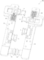
- FIG. 7 is a schematic diagram of a partially exploded structure of the folding device shown in FIG. 2;
- FIG. 8 is a schematic diagram of a partially exploded structure of the rotating mechanism shown in FIG. 7;
- Fig. 9 is a schematic structural diagram of the folding device shown in Fig. 2 at another angle;
- FIG. 10 is a partially exploded structural schematic diagram of a partial structure of the folding device shown in FIG. 2; FIG.
- Fig. 11 is a schematic diagram of an exploded structure of the main shaft shown in Fig. 10;
- Fig. 12 is a schematic structural diagram of the main outer shaft shown in Fig. 11 at another angle;
- Fig. 13 is a schematic structural view of the main shaft shown in Fig. 10 taken along line A-A;
- Fig. 14 is a schematic structural view of the main shaft shown in Fig. 10 taken along the line B-B;
- Figure 15 is a structural schematic diagram of the main shaft shown in Figure 10 cut along the line C-C
- Fig. 16 is a schematic structural view of the main shaft shown in Fig. 10 taken along the line D-D;
- Fig. 17 is a schematic structural view of the main shaft shown in Fig. 10 taken along the line E-E;
- Fig. 18 is a schematic structural diagram of the end connection assembly shown in Fig. 10 at another angle;
- Fig. 19 is a partial exploded structural diagram of the end connection assembly shown in Fig. 18;
- FIG. 20 is an exploded structural diagram of the first fixing frame of the end connection assembly shown in FIG. 19;
- FIG. 21 is an exploded structural diagram of the second fixing frame of the end connection assembly shown in FIG. 19;
- Fig. 22 is a schematic structural view of a first limiting member of the end connection assembly shown in Fig. 19;
- FIG. 23 is a schematic diagram of an exploded structure of the first limiting member shown in FIG. 22;
- Figure 24 is a schematic structural view of the first transmission arm of the end connecting assembly shown in Figure 19;
- FIG. 25 is a schematic diagram of the structure of the first rotating arm of the end connecting assembly shown in FIG. 19;
- FIG. 26 is a schematic structural diagram of the first synchronous swing arm of the end connection assembly shown in FIG. 19;
- Fig. 27 is a schematic structural diagram of the middle connecting assembly shown in Fig. 10 from another angle;
- Fig. 28 is an exploded structural diagram of the middle connecting assembly shown in Fig. 27;
- Fig. 29 is a partial structural diagram of the rotating mechanism shown in Fig. 7;
- Figure 30 is a schematic diagram of a part of the structure of the folding device shown in Figure 2;
- Figure 31 is a schematic diagram of a part of the structure of the folding device shown in Figure 2;
- Fig. 32 is a schematic diagram of the connection relationship between a part of the structure of the end connection assembly shown in Fig. 8 and the main shaft;
- FIG. 33 is a schematic cross-sectional structure diagram of the folding device shown in FIG. 2 corresponding to the position of the first transmission arm;
- FIG. 34 is a schematic cross-sectional structure diagram of the folding device shown in FIG. 4 corresponding to the position of the first transmission arm;
- 35 is a schematic cross-sectional structure diagram of the folding device shown in FIG. 6 corresponding to the position of the first transmission arm;
- FIG. 36 is a schematic cross-sectional structure diagram of the folding device shown in FIG. 2 corresponding to the position of the first rotating arm;
- FIG. 37 is a schematic cross-sectional structure diagram of the folding device shown in FIG. 4 corresponding to the position of the first rotating arm;
- FIG. 38 is a schematic cross-sectional structure diagram of the folding device shown in FIG. 6 corresponding to the position of the first rotating arm;
- FIG. 39 is a schematic cross-sectional structure diagram of the folding device shown in FIG. 2 corresponding to the position of the second transmission arm;
- FIG. 40 is a schematic cross-sectional structure diagram of the folding device shown in FIG. 4 corresponding to the position of the second transmission arm;
- 41 is a schematic cross-sectional structure diagram of the folding device shown in FIG. 6 corresponding to the position of the second transmission arm;
- FIG. 42 is a schematic cross-sectional structure diagram of the folding device shown in FIG. 2 corresponding to the position of the second rotating arm;
- FIG. 43 is a schematic cross-sectional structure diagram of the folding device shown in FIG. 4 corresponding to the position of the second rotating arm;
- FIG. 44 is a schematic cross-sectional structure diagram of the folding device shown in FIG. 6 corresponding to the position of the second rotating arm;
- FIG. 45 is a schematic cross-sectional structure diagram of the folding device shown in FIG. 2 corresponding to the positions of the first synchronous swing arm and the second synchronous swing arm;
- FIG. 46 is a schematic cross-sectional structure diagram of the folding device shown in FIG. 4 corresponding to the positions of the first synchronous swing arm and the second synchronous swing arm;
- Fig. 47 is a schematic cross-sectional structure diagram of the folding device shown in Fig. 6 corresponding to the positions of the first synchronous swing arm and the second synchronous swing arm.
- the embodiments of the present application provide a folding device and an electronic device.
- the electronic device includes a folding device and a flexible display screen fixed to the folding device.
- the folding device can be expanded to a flat state, can also be folded to a closed state, and can also be in an intermediate state between the flat state and the closed state.
- the flexible display screen is unfolded and folded with the folding device.
- the electronic device can rotate with the flexible display screen as the neutral surface, thereby reducing the risk of pulling or squeezing the flexible display screen, so as to protect the flexible display screen and improve the reliability of the flexible display screen. , So that the flexible display screen and electronic equipment have a long service life.
- FIG. 1 is a schematic structural diagram of an electronic device 1000 in an unfolded state according to an embodiment of the present application
- FIG. 2 is a schematic structural diagram of a folding device 100 of the electronic device 1000 shown in FIG. 1 3 is a schematic structural diagram of the electronic device 1000 shown in FIG. 1 in an intermediate state
- FIG. 4 is a schematic structural diagram of the folding device 100 of the electronic device 1000 shown in FIG. 3
- FIG. 5 is a closed state of the electronic device 1000 shown in FIG.
- Fig. 6 is a schematic structural diagram of the folding device 100 of the electronic device 1000 shown in Fig. 5.
- the electronic device 1000 may be a product such as a mobile phone, a tablet computer, or a notebook computer. In this embodiment, the electronic device 1000 is a mobile phone as an example for description.
- the electronic device 1000 includes a folding device 100 and a flexible display screen 200.
- the folding device 100 includes a first housing 10, a rotating mechanism 20, and a second housing 30 connected in sequence.
- the rotating mechanism 20 can be deformed so that the first housing 10 and the second housing 30 are relatively folded or relatively unfolded.
- the first housing 10 and the second housing 30 can be relatively expanded to a flat state, so that the electronic device 1000 is in a flat state.
- the first housing 10 and the second housing 30 may be approximately 180° (a slight deviation is also allowed, such as 165°, 177°, or 185°).
- the first housing 10 and the second housing 30 can be relatively rotated (expanded or folded) to an intermediate state, so that the electronic device 1000 is in an intermediate state.
- the first housing 10 and the second housing 30 can be relatively folded to a closed state, so that the electronic device 1000 is in a closed state.
- the intermediate state shown in FIG. 3 and FIG. 4 can be any state between the flat state and the closed state. Therefore, the electronic device 1000 can switch between the flat state and the closed state through the deformation of the rotating mechanism 20.
- the flexible display 200 is used to display images.
- the flexible display 200 may be an organic light-emitting diode (OLED) display, an active-matrix organic light-emitting diode, or an active-matrix organic light-emitting diode (active-matrix organic light-emitting diode).
- OLED organic light-emitting diode
- AMOLED active-matrix organic light-emitting diode
- mini organic light-emitting diode display micro organic light-emitting diode display
- micro organic light-emitting diode display micro organic light-emitting diode display
- quantum Quantum dot light emitting diode (QLED) display screen QLED
- the flexible display 200 includes a first non-bending portion 2001, a bending portion 2002, and a second non-bending portion 2003 arranged in sequence.
- the flexible display screen 200 is fixed to the folding device 100.
- the flexible display screen 200 may be adhered to the folding device 100 through an adhesive layer.
- the first non-bending portion 2001 of the flexible display 200 is fixed to the first housing 10, and the second non-bending portion 2003 is fixed to the second housing 30.
- the first housing 10 and the second housing 30 are folded or folded relative to each other.
- the bending portion 2002 is deformed.
- FIG. 1 when the first housing 10 and the second housing 30 are in a flat state, the flexible display screen 200 is in a flat state; as shown in FIG.
- the first housing 10 and the second housing 30 are in a flat state.
- the flexible display screen 200 is in an intermediate state between the flattened state and the closed state; as shown in FIG. 5, when the first housing 10 and the second housing 30 are in the closed state, the flexible display screen 200 is in the closed state .
- the flexible display screen 200 when the electronic device 1000 is in the closed state, the flexible display screen 200 is located outside the folding device 100, and the flexible display screen 200 may be roughly U-shaped.
- the flexible display screen 200 can be unfolded or folded with the folding device 100.
- the flexible display screen 200 is in a flattened form and can display in full screen, so that the electronic device 1000 has a larger display area, so as to improve the user's viewing experience.
- the planar size of the electronic device 1000 is small (having a small width size), which is convenient for the user to carry and store.
- the rotation center of the electronic device 1000 is parallel to the width direction of the electronic device 1000" as an example.
- the electronic device 1000 can be rotated left and right, and the electronic device 1000 can be folded and unfolded. Affect the width dimension of the electronic device 1000.
- the rotation center of the electronic device 1000 may also be parallel to the length direction of the electronic device 1000. At this time, the electronic device 1000 can rotate up and down, and the folding and unfolding of the electronic device 1000 affects the length of the electronic device 1000. .
- FIG. 7 is a partially exploded structural diagram of the folding device 100 shown in FIG. 2
- FIG. 8 is a partially exploded structural diagram of the rotating mechanism 20 shown in FIG. 7.
- none of the drawings in this application illustrate the fasteners in the folding device 100, so as to simplify the drawings and illustrate the main structure of the folding device 100 more clearly.
- the rotating mechanism 20 of the folding device 100 includes a main shaft 1, an end connecting component 20a, a middle connecting component 20b, a first supporting plate 21, a second supporting plate 22, a first shielding plate 23, and a second shielding plate 24 .
- the main shaft 1 is located between the first housing 10 and the second housing 30.
- the end connecting component 20 a connects the first housing 10, the main shaft 1 and the second housing 30.
- the number of the end connection components 20a is two, and the two end connection components 20a are arranged at intervals in the axial direction of the main shaft 1, for example, can be connected to the top and bottom of the main shaft 1 respectively.
- the middle connecting component 20 b connects the first housing 10, the main shaft 1 and the second housing 30.
- the middle connecting component 20b is located between the two end connecting components 20a.
- the first support plate 21 and the second support plate 22 are located on one side of a plurality of connecting components (that is, the two end connecting components 20a and the middle connecting component 20b), and the first shielding plate 23 and the second shielding plate 24 are located on multiple connecting components. Connect the other side of the assembly (20a, 20b).
- the first supporting plate 21 is located on the side of the main shaft 1 facing the first housing 10, and the first supporting plate 21 is connected to the end connecting assembly 20a. In some embodiments, the first support plate 21 can also be connected to the middle connecting component 20b.
- the second supporting plate 22 is located on the side of the main shaft 1 facing the second housing 30, and the second supporting plate 22 is connected to the end connecting assembly 20a. In some embodiments, the second support plate 22 may also be connected to the middle connecting component 20b.
- the first housing 10 has a first supporting surface 101, and the first supporting surface 101 is used to support the flexible display screen 200.
- the second housing 30 has a second supporting surface 301, and the second supporting surface 301 is used to support the flexible display screen 200.
- the first supporting surface 101 and the second supporting surface 301 are flush to better support the flexible display screen 200, making the flexible display screen 200 more compact. It is flat and helps to improve the user experience.
- the main shaft 1 has a supporting surface 11.
- the supporting surface 11 of the main shaft 1 is partially exposed relative to the first supporting plate 21 and the second supporting plate 22.
- the first support plate 21, the main shaft 1 and the second support plate 22 can jointly support the bending portion 2002 of the flexible display screen 200, so that the flexible display screen 200 is flatter, and is not easily damaged by external touch, so as to improve the flexible display screen. 200 reliability.
- the supporting surface 11 of the spindle 1 is partially exposed relative to the first supporting plate 21 and the second supporting plate 22, and the supporting surface of the spindle 1
- the exposed area 11 is larger than the exposed area in the flat state.
- the supporting surface 11 of the spindle 1 and the first supporting plate 21 and the second supporting plate 22 jointly support the bending portion 2002 of the flexible display screen 200.
- the supporting surface 11 of the spindle 1 is completely exposed relative to the first supporting plate 21 and the second supporting plate 22, and the supporting surface of the spindle 1 11
- the bending part 2002 of the flexible display screen 200 is supported.
- the supporting surface 11 of the main shaft 1 is arc-shaped.
- the main shaft 1 can provide a complete semicircular or nearly semicircular support for the bending portion 2002 of the flexible display screen 200, which is similar to that of the flexible display screen 200.
- the ideal closed shape of the bent portion 2002 is kept consistent, so that a more optimized support can be provided for the flexible display screen 200 in the closed shape.
- the central angle of the supporting surface 11 of the main shaft 1 may be in the range of 150° to 180° to better support the flexible display screen 200.
- the supporting surface 11 of the main shaft 1 is arc-shaped.
- One is the supporting surface 11 of the main shaft 1 being a standard arc, and the other is the supporting surface of the main shaft 1.
- 11 The overall shape is approximately arc.
- the supporting surface 11 of the main shaft 1 may also have other shapes.
- the supporting surface 11 of the main shaft 1 is set in a semi-elliptical shape to reduce the width of the folding device 100 when it is in the closed state, so that it is easier to carry and store.
- the implementation of the application does not strictly limit the shape of the supporting surface of the main shaft 1.
- FIG. 9 is a schematic structural diagram of the folding device 100 shown in FIG. 2 at another angle.
- the viewing angle of the folding device 100 of FIG. 9 is the viewing angle of the viewing angle of FIG. 2 after being flipped.
- the first shielding plate 23 is located on the side of the main shaft 1 facing the first housing 10, and the first shielding plate 23 is connected to the end connecting assembly 20a. In some embodiments, the first shielding plate 23 can also be connected to the middle connecting component 20b.
- the second shielding plate 24 is located on the side of the main shaft 1 facing the second housing 30, and the second shielding plate 24 is connected to the end connecting assembly 20a. In some embodiments, the second shielding plate 24 can also be connected to the middle connecting assembly 20b.
- the main shaft 1 has a shielding surface 12.
- the shielding surface 12 of the spindle 1 is exposed to the first shielding plate 23 and the second shielding plate 24; the first shielding plate 23 is located in the first housing 10 Between the main shaft 1 and the first housing 10, the gap between the first housing 10 and the main shaft 1 can be shielded; the second shielding plate 24 is located between the second housing 30 and the main shaft 1, and can shield the second housing 30 and the main shaft 1 Therefore, the rotating mechanism 20 can jointly shield the gap between the first housing 10 and the second housing 30 through the first shielding plate 23, the spindle 1 and the second shielding plate 24 in the flat state, thereby realizing the self
- the shielding is beneficial to improve the integrity of the appearance, and can also reduce the risk of external dust and debris entering the rotating mechanism 20, so as to ensure the reliability of the folding device 100.
- FIG. 10 is a partially exploded schematic diagram of a partial structure of the folding device 100 shown in FIG. 2.
- a plurality of movable spaces connected to the outside of the main shaft 1 are formed inside the main shaft 1, and a plurality of connecting components (20a, 20b) of the rotating mechanism 20 are movably installed in these movable spaces to connect the main shaft 1.
- the rotation center of the entire rotating mechanism 20 is parallel to the axial direction of the main shaft 1, and the main shaft 1 extends along the axial direction.
- the structure of the two end connecting components 20a is mirror-symmetrical. At this time, since the structures of the two end connecting assemblies 20a are the same, the overall structure of the rotating mechanism 20 is relatively simple and the processing cost is low. Since the two end connecting components 20a are arranged in mirror symmetry, the stress between the two end connecting components 20a and the main shaft 1, the first housing 10 and the second housing 30 during the rotation of the folding device 100 It is more uniform, which helps to improve the reliability of the folding device 100. In some other embodiments, the structures of the two end connecting components 20a may also be different.
- the structure of the middle connecting component 20b is simpler than that of the end connecting component 20a.
- the rotating mechanism 20 has two end connecting components 20a to realize the main connection and control function, and the middle connecting component 20b realizes the auxiliary connection and control function. .
- the rotating mechanism 20 may not be provided with the middle connecting component 20b.
- the rotating mechanism 20 can also set the connecting component located in the middle as the main connecting component (for example, the structure of the connecting component can refer to the structure of the end connecting component 20a in FIG. 10), which is located at the end.
- the connecting component of is set as an auxiliary connecting component (for example, the structure of the connecting component can refer to the structure of the middle connecting component 20b in FIG. 10).
- the embodiment of the present application may also be provided with only one end connecting assembly 20a, and the end connecting assembly 20a connects the middle of the main shaft 1 with the middle of the first housing 10 and the middle of the second housing 30. It can be understood that the structure of the rotating mechanism 20 can have various combinations and deformation modes, which are not strictly limited in the embodiment of the present application.
- FIG. 11 is an exploded structural diagram of the main shaft 1 shown in FIG. 10, and FIG. 12 is a structural diagram of the main outer shaft 14 shown in FIG. 11 at another angle.
- the main shaft 1 includes a main outer shaft 14, a main inner shaft 15 and a shielding plate 16.
- the main outer shaft 14 is fixed on one side of the main inner shaft 15, and the shielding plate 16 is fixed on the other side of the main inner shaft 15.
- the supporting surface 11 of the main shaft 1 is formed on the main outer shaft 14 and is arranged away from the main inner shaft 15.
- the shielding surface 12 of the main shaft 1 is formed on the shielding plate 16 and is arranged away from the main outer shaft 14.
- the shielding plate 16 may be fixed to the main inner shaft 15 in an assembled manner.
- the shielding plate 16 and the main inner shaft 15 may also be integrally formed structural members.
- Both the main inner shaft 15 and the main outer shaft 14 are provided with multiple three-dimensional space structures. Through the design of these structures, the main inner shaft 15 and the main outer shaft 14 can be assembled together to form multiple movable spaces and multiple connecting components.
- the structural members (20a, 20b) are movably installed in multiple movable spaces of the main shaft 1, so as to realize the connection with the main shaft 1.
- the separate design of the main inner shaft 15 and the main outer shaft 14 is beneficial to reduce the manufacturing difficulty of the main shaft 1 and improve the manufacturing accuracy and product yield of the main shaft 1.
- the main inner shaft 15 includes a main inner shaft body 151, a plurality of grooves 152, a plurality of protrusions 153, two end stops 154 and a plurality of fastening holes 155.
- a plurality of grooves 152 and a plurality of protrusions 153 are formed on the main inner shaft body 151, and they are combined with each other to form a plurality of three-dimensional space structures.
- Two end stoppers 154 are fixed to the two ends of the main inner shaft body 151.
- a plurality of fastening holes 155 are formed in the main inner shaft body 151. Wherein, in FIG. 11, the numbers of part of the groove 152, part of the bump 153 and part of the fastening hole 155 are schematically marked.
- the main outer shaft 14 includes a main outer shaft body 141, two limiting flanges 142, a plurality of grooves 143, a plurality of protrusions 144 and a plurality of fastening holes 145.
- Two limiting flanges 142 are respectively fixed to two sides of the main outer shaft body 141 at intervals, and the limiting flanges 142 extend along the extension direction of the main shaft 1.
- a plurality of grooves 143 and a plurality of protrusions 144 are formed on the main outer shaft body 141, and they are combined with each other to form a plurality of three-dimensional spatial structures.
- a plurality of fastening holes 145 are formed in the main outer shaft body 141. Wherein, the numbers of part of the groove 143, part of the bump 144 and part of the fastening hole 145 are schematically marked in FIG. 12.
- the main inner shaft 15 is aligned with the plurality of fastening holes 145, and the main inner shaft 15 and the main outer shaft 14 are fixed by fasteners (not shown in the figure).
- fasteners include but are not limited to screws, bolts, rivets, pins, etc.
- the multiple three-dimensional space structures of the main outer shaft 14 and the multiple three-dimensional space structures of the main inner shaft 15 jointly form a plurality of movable spaces of the main shaft 1.
- part of the activity space structure of the multiple activity spaces is the same, and part of the activity space structure is different.
- the movable spaces with different structures are used to cooperate with the structural parts with different structures, so that the connection structure of the main shaft 1 and the multiple connection components (20a, 20b) is more flexible and diversified.
- the movable space with the same structure is used to cooperate with the structural parts with the same structure, which is beneficial to reduce the design difficulty and cost of the main shaft 1 and the connecting assembly.
- part of the convex block 153 of the main inner shaft 15 has a limiting groove 1531 for limiting the structural components installed in the corresponding movable space in the axial direction of the main shaft 1.
- a part of the limiting groove 1531 is schematically marked in FIG. 11.
- the groove wall of part of the groove 143 of the main outer shaft 14 is provided with a limiting groove 1431 to limit the structural components installed in the corresponding movable space in the axial direction of the main shaft 1 to Improve the reliability of the connection structure.
- Part of the limiting groove 1431 is schematically marked in FIG. 12.
- a limit groove (1531/1431) is provided in the same movable space, which can limit the position of the structural member in the axial direction of the main shaft 1.
- two limiting grooves (1531, 1431) may also be provided in the same activity space, which is not strictly limited in the embodiment of the present application.
- part of the protrusions 144 of the main outer shaft 14 has a position limiting function.
- the component is restricted to prevent the structural component from accidentally detaching from the main shaft 1, so as to improve the connection reliability and movement reliability of the connecting assembly (20a, 20b) and the main shaft 1, making the rotation mechanism 20 and the folding device 100 more reliable.
- the main shaft 1 may also be provided with a protrusion for limiting the position on the main inner shaft 15.
- FIG. 13 is a schematic diagram of the structure of the spindle 1 shown in FIG. 10 taken along the line AA
- FIG. 14 is a schematic diagram of the structure of the spindle 1 shown in FIG. 10 taken along the line BB
- Fig. 17 is a structural diagram of the main shaft 1 shown in Fig. 10 taken along the line EE.
- the main shaft 1 of the present embodiment forms a variety of movable spaces with different shapes for matching with different structural parts.
- the main outer shaft 14 and the main inner shaft 15 are jointly enclosed to form an arc-shaped groove 131.
- the center of the arc-shaped groove 131 is close to the main inner shaft 15 and far away from the main outer shaft 14 to form a movable space.
- the movable space may further include a limiting groove 1531 communicating with the arc-shaped groove 131, and the limiting groove 1531 is formed on the main inner shaft 13.
- the main outer shaft 14 may further include a protrusion 144 with a limiting effect, and the protrusion 144 extends into the arc-shaped groove 131 to limit the structure installed in the movable space.
- the main outer shaft 14 and the main inner shaft 15 are jointly enclosed to form an arc-shaped groove 131.
- the center of the arc-shaped groove 131 is close to the main inner shaft 15 and far away from the main outer shaft 14 to form a movable space.
- the arc-shaped groove 131 shown in FIG. 13 and the arc-shaped groove 131 shown in FIG. 14 are arranged in pairs.
- the movable space may further include a limiting groove 1531 communicating with the arc-shaped groove 131, and the limiting groove 1531 is formed on the main inner shaft 15.
- the main outer shaft 14 may further include a protrusion 144 with a limiting effect, and the protrusion 144 extends into the arc-shaped groove 131 to limit the structure installed in the movable space.
- the main outer shaft 14 and the main inner shaft 15 are jointly enclosed to form an arc-shaped groove 131.
- the center of the arc-shaped groove 131 is close to the main outer shaft 14 and far away from the main inner shaft 15 to form a movable space.
- the movable space may further include a limiting groove 1431 communicating with the arc-shaped groove 131, and the limiting groove 1431 is formed on the main outer shaft 14.
- the main outer shaft 14 may further include a protrusion 144 with a limiting effect, and the protrusion 144 extends into the arc-shaped groove 131 to limit the structure installed in the movable space.
- the main outer shaft 14 and the main inner shaft 15 are jointly enclosed to form an arc-shaped groove 131.
- the center of the arc-shaped groove 131 is close to the main outer shaft 14 and far away from the main inner shaft 15 to form a movable space.
- the arc-shaped groove 131 shown in FIG. 15 and the arc-shaped groove 131 shown in FIG. 16 are arranged in pairs.
- the movable space may further include a limiting groove 1431 communicating with the arc-shaped groove 131, and the limiting groove 1431 is formed on the main outer shaft 14.
- the main outer shaft 14 may further include a protrusion 144 with a limiting effect, and the protrusion 144 extends into the arc-shaped groove 131 to limit the structure installed in the movable space.
- the main inner shaft 15 and the main outer shaft 14 of the main shaft 1 jointly define a plurality of arc-shaped grooves 131.
- the arc-shaped grooves 131 at different positions can be connected with different structural members of the connecting assembly (20a, 20b).
- the main outer shaft 14 and the main inner shaft 15 are jointly surrounded by an M-shaped groove 132.
- the side wall of the M-shaped groove 132 forms two spaced-apart recessed grooves 133.
- the grooves 133 collectively form an activity space.
- main shaft 1 in the embodiment of the present application may also have other structures, which is not strictly limited in the present application.
- FIG. 18 is a schematic structural diagram of the end connecting assembly 20a shown in FIG. 10 at another angle
- FIG. 19 is a partially exploded structural diagram of the end connecting assembly 20a shown in FIG. 18.
- the end connecting assembly 20a of the rotating mechanism 20 includes a first fixing frame 31, a second fixing frame 32, a first transmission arm 4, a first rotation arm 5, a second transmission arm 6, and a second rotation arm 7. .
- the rotating mechanism 20 may further include a first limiting member 81 and a second limiting member 82.
- the rotating mechanism 20 may further include a first synchronous swing arm 91 and a second synchronous swing arm 92.
- FIG. 20 is an exploded structural diagram of the first fixing frame 31 of the end connecting assembly 20a shown in FIG. 19.
- the first fixing frame 31 includes a first fixing base 311 and a first fastening member 312.
- the first fastening member 312 is fixed to the first fixing base 311 and encloses the first fixing base 311 together.
- a first arc-shaped slot 313 is provided.
- the first fastener 312 may be fixed to the first fixing base 311 by a fastener.
- the first fixing frame 31 may also be an integrally formed structure.
- the first fastener 312 has an arc surface for enclosing the first arc-shaped groove 313, and a limiting groove 3121 is formed in the middle of the arc surface to be in the axial direction of the main shaft 1. In the direction, the structural member installed in the first arc-shaped slot 313 is restricted to improve the reliability of the connection structure.
- the limiting groove may also be formed on the arc surface of the first fixed base 311 for enclosing the first arc groove 313.
- the first fastening member 312 may also have a stop block 3122 for preventing the structural member installed in the first arc-shaped slot 313 from accidentally escaping from the first arc-shaped slot 313.
- the first fixing base 311 of the first fixing frame 31 may further have a first sliding groove 314 and a first mounting groove 315, and the first mounting groove 315 is connected to the first sliding groove 314.
- the side wall of the first sliding groove 314 may have a recessed guide space 3141.
- the first fixing base 311 of the first fixing frame 31 may further have a third sliding groove 316, and the groove wall of the third sliding groove 316 has a recessed guide space 3161.
- the guiding direction of the guiding space 3161 of the third sliding groove 316 is the same as the guiding direction of the guiding space 3141 of the first sliding groove 314.
- the first sliding groove 314, the third sliding groove 316, and the first arc-shaped groove 313 are all formed on the same structural member, and the first fixed base 311 is an integrally formed structural member. .
- the first sliding groove 314, the third sliding groove 316, and the first arc-shaped groove 313 may also be formed on different structural members.
- the first fixed base 311 may include multiple structural members. There is no strict restriction on this.
- the first fixing base 311 of the first fixing frame 31 has a plurality of fastening holes 3111.
- the rotating mechanism 20 can fix the first fixing frame 31 to the first housing 10 by a plurality of fasteners.
- the first fixing frame 31 may also have positioning protrusions 3112, and the positioning protrusions 3112 are used to cooperate with the first housing 10 so as to make the connection between the first fixing frame 31 and the first housing 10. The assembly precision and stability of the structure are higher.
- FIG. 21 is an exploded structural diagram of the second fixing frame 32 of the end connecting assembly 20a shown in FIG. 19.
- the structure of the second fixing frame 32 is similar to the structure of the first fixing frame 31.
- the second fixing frame 32 includes a second fixing base 321 and a second fastening member 322.
- the second fastening member 322 is fixed to the second fixing base 321, and together with the second fixing base 321 surrounds the second fixing base 321.
- the structure of the second fastener 322 may be the same as the structure of the first fastener 312.
- the second fixing base 321 of the second fixing frame 32 may further have a second sliding groove 324 and a second mounting groove 325, and the second mounting groove 325 is connected to the second sliding groove 324.
- the side wall of the second sliding groove 324 has a recessed guide space 3241.
- the structure of the second sliding groove 324 and the second mounting groove 325 may be the same as the structure of the first sliding groove 314 and the first mounting groove 315 of the first fixing frame 31.
- the second fixing base 321 of the second fixing frame 32 may further have a fourth sliding groove 326, and the groove wall of the fourth sliding groove 326 has a recessed guide space 3261.
- the structure of the fourth sliding groove 326 may be the same as the structure of the second sliding groove 324 of the first fixing frame 31.
- the positions of the plurality of grooves on the second fixing frame 32 may be different from the positions of the plurality of grooves on the first fixing frame 31, for example, they may be misaligned and arranged in the axial direction parallel to the main shaft 1, so as to be aligned with the second fixing frame.
- a plurality of structural members connected by 32 may be arranged in the axial direction of the main shaft 1 to improve the space utilization rate of the rotating mechanism 20.
- FIG. 22 is a schematic structural diagram of the first limiting member 81 of the end connecting assembly 20a shown in FIG. 19, and FIG. 23 is an exploded structural diagram of the first limiting member 81 shown in FIG. 22 .
- the first limiting member 81 includes a first bracket 811 and a first elastic member 812.
- the first bracket 811 is a rigid structure and is not easily deformed under the action of external force.
- the first bracket 811 includes a control portion 8111 and a resisting portion 8112.
- the resisting portion 8112 is used to resist the external structural member to limit the structural member.
- the control part 8111 is used to control the position of the resisting part 8112.
- the control portion 8111 includes a substrate 8113 and a plurality of guide posts 8114, and the plurality of guide posts 8114 are fixed to one side of the substrate 8113 at intervals.
- the resisting portion 8112 is fixed to the other side of the substrate 8113.
- the first elastic member 812 is an elastic structure and is prone to deformation under the action of external force.
- One end of the first elastic member 812 is installed on the control portion 8111 of the first bracket 811.
- the first elastic member 812 may include a plurality of springs 8121, and the plurality of springs 8121 are sleeved on the plurality of guide posts 8114 in a one-to-one correspondence.
- the first limiting member 81 is installed in the first installation groove 315 of the first fixing frame 31.
- the other end of the first elastic member 812 (that is, the end away from the control portion 8111) abuts against the wall of the first mounting groove 315, the first elastic member 812 is in a compressed state, and the resisting portion 8112 of the first bracket 811 partially extends into First chute 314.
- the first limiting member 81 may further include a first buffer member 813, and the first buffer member 813 is installed on the resisting portion 8112 of the first bracket 811.
- the first buffer member 813 may be made of a material with less rigidity (such as rubber, etc.), so as to be able to absorb the impact force through deformation when receiving an external force, so as to achieve buffering.
- the first limiting member 81 is provided with the first buffer member 813 to buffer the stress between the resisting portion 8112 and the structural member, thereby improving the reliability of the limiting structure.
- the first bracket 811 of the first limiting member 81 may further include a positioning portion 8115.
- the positioning portion 8115 is fixed below the resisting portion 8112 and extends in a direction away from the control portion 8111 relative to the resisting portion 8112. When the structural member is resisted by the resisting portion 8112, the positioning portion 8115 can play a role in positioning and supporting the structural member, thereby improving the reliability of the limiting structure.
- the structure of the second limiting member 82 may be similar to or the same as the structure of the first limiting member 81 to serve as a limiting function.
- FIG. 24 is a structural diagram of the first transmission arm 4 of the end connecting assembly 20 a shown in FIG. 19.
- the first transmission arm 4 includes a sliding end 41 and a rotation end 42, and the sliding end 41 and the rotation end 42 of the first transmission arm 4 are fixed to each other.
- the first transmission arm 4 may be an integrally formed structural member.
- the sliding end 41 of the first transmission arm 4 has a first recessed area 411 and a second recessed area 412, and the second recessed area 412 is located between the first recessed area 411 and the rotating end 42 of the first transmission arm 4 .
- the sliding end 41 of the first transmission arm 4 includes a first flange 413 on the peripheral side.
- the first recessed area 411 and the second recessed area 412 are formed on the first flange 413.
- the sliding end 41 of the first transmission arm 4 is installed in the first sliding groove 314, and the first flange 413 is installed in the guiding space 3141 of the first sliding groove 314.
- the sliding end 41 of the first transmission arm 4 can be guided to slide in the first sliding groove 314.
- the direction makes the relative sliding action between the first transmission arm 4 and the first fixing frame 31 easier to realize and higher control accuracy.
- the first limiting member 81 is clamped to the sliding end 41 of the first transmission arm 4, so as to limit the first transmission arm 4, so that the first transmission arm 4 and the first fixing frame 31 can be free from a large external force. Maintaining the preset relative position relationship, the rotating mechanism 20 can stay at a preset angle, and the rotating device can remain in a flat state or a closed state, so as to improve the user experience of the folding device 100 and the electronic device 1000.
- the first limiting member 81 when the first housing 10 and the second housing 30 are relatively unfolded to a flat state, the first limiting member 81 is partially clamped into the first recessed area 411, and the first housing 10 and the second housing 30 are opposite to each other. When folded to the closed state, the first limiting member 81 partially engages in the second recessed area 412.
- the resisting portion 8112 of the first bracket 811 of the first limiting member 81 is clamped to the sliding end 41 of the first transmission arm 4.
- the first elastic member 812 of the first limiting member 81 can be deformed under the action of external force, so that the first limiting member 81 can be opposed to the sliding end 41 of the first transmission arm 4 in the first recessed area 411 and the second recessed area.
- the smooth movement between the regions 412 improves the reliability of the limit between the first limit member 81 and the sliding end 41 of the first transmission arm 4.
- the first limiting member 81 abuts the sliding end 41 of the first transmission arm 4 through the first buffer member 813 having a buffering effect. This helps to reduce the risk of wear of the first bracket 811 and the first transmission arm 4 during the long-term relative movement, improves the reliability of the first limit member 81, and makes the rotating assembly more reliable.
- two adjacent surfaces of the first flange 413 of the first transmission arm 4 respectively resist the resisting portion 8112 of the first bracket 811 and the positioning portion 8115 of the first bracket 811, and the first flange 413 can It slides relative to the positioning portion 8115 of the first bracket 811.
- the positioning portion 8115 of the first bracket 811 By providing the positioning portion 8115 of the first bracket 811, the limiting connection relationship between the first limiting member 81 and the sliding end 41 of the first transmission arm 4 is more reliable, so as to improve the reliability of the rotating assembly.
- the rotating end 42 of the first transmission arm 4 is arc-shaped. 13 and 24 in combination, the rotating end 42 of the first transmission arm 4 can be installed in one of the arc-shaped grooves 131 of the main shaft 1 so that the first transmission arm 4 is connected to the main shaft 1 in rotation. At this time, the rotation center of the relative rotation of the first transmission arm 4 and the main shaft 1 is close to the main inner shaft 15 and far away from the main outer shaft 14.
- the first transmission arm 4 and the main shaft 1 are connected by a virtual shaft, the rotating connection structure is simple, and the space occupied is small, which is beneficial to reduce the thickness of the rotating mechanism 20, making the folding device 100 and the electronic device 1000 easier to implement Thin and light.
- the first transmission arm 4 and the main shaft 1 may also be connected by a real shaft, which is not strictly limited in the embodiment of the present application.
- the rotating end 42 of the first transmission arm 4 includes a limiting protrusion 421 and a limiting protrusion 422.
- the limiting protrusion 421 forms an inner position of the rotating end 42, and the limiting protrusion 422 is formed on the rotating end 42. End position.
- the limiting protrusion 421 is used to cooperate with the limiting groove 1531 of the main shaft 1 (refer to FIG. 13), so that the first transmission arm 4 and the main shaft 1 are mutually limited in the axial direction of the main shaft 1.
- the limiting protrusion 422 is used to cooperate with the limiting protrusion 144 (refer to FIG. 13) of the main shaft 1 to prevent the first transmission arm 4 from accidentally detaching from the main shaft 1.
- the structure of the second transmission arm 6 may be the same as the structure of the first transmission arm 4.
- the second transmission arm 6 includes a sliding end 61 and a rotating end 62.
- the sliding end 61 of the second transmission arm 6 is slidably connected to the second fixing frame 32.
- the sliding end 61 of the second transmission arm 6 can be installed in the second sliding groove 324 of the second fixing frame 32.
- the second fixing frame 32 may be installed with a second limiting member 82 for limiting the relative movement between the sliding end 61 of the second transmission arm 6 and the second fixing frame 32.
- the rotating end 62 of the second transmission arm 6 is rotatably connected to the main shaft 1.
- the rotating end 62 of the second transmission arm 6 is arc-shaped and is installed in an arc-shaped slot 131 of the main shaft 1. At this time, the rotation center of the relative rotation of the second transmission arm 6 and the main shaft 1 is close to the main inner shaft 15 and far away from the main outer shaft 14.
- the second transmission arm 6 and the main shaft 1 are connected by a virtual shaft.
- the first transmission arm 4 and the main shaft 1 may also be connected by a real shaft. Not strictly limited.
- FIG. 25 is a structural diagram of the first rotating arm 5 of the end connecting assembly 20a shown in FIG. 19.
- both ends of the first rotating arm 5 are rotating ends.
- One end 51 of the first rotating arm 5 rotatably connected to the first fixing frame 31 is arc-shaped and is installed in the first arc-shaped slot 313.
- one end 51 of the first rotating arm 5 includes a limiting protrusion 511 and a limiting protrusion 512.
- the limiting protrusion 511 is used to cooperate with the limiting groove 3121 of the first arc-shaped groove 313.
- the limiting protrusion 512 is used to cooperate with the stopping block 3122 of the first fixing frame 31.
- one end 52 of the first rotating arm 5 rotatably connected to the main shaft 1 is arc-shaped and is installed in an arc-shaped slot 131 of the main shaft 1.
- the rotation center of the relative rotation of the first rotating arm 5 and the main shaft 1 is close to the main outer shaft 14 and far away from the main inner shaft 15.
- one end 52 of the first rotating arm 5 includes a limiting protrusion 521 and a limiting protrusion 522.
- the limiting protrusion 521 is used to cooperate with the limiting sink 1431 of the main shaft 1.
- the limiting protrusion 522 is used to cooperate with the protrusion 144 of the spindle 1.
- the first rotating arm 5 is roughly "W"-shaped.
- the first rotating arm 5 and the first fixing frame 31 are connected by a virtual shaft, and the first rotating arm 5 and the main shaft 1 are also connected by a virtual shaft, so that the rotating connection structure is simple, the space is small, and the rotating mechanism is reduced.
- the thickness of 20 makes it easier for the folding device 100 and the electronic device 1000 to be thinner and lighter.
- the first rotating arm 5 and the first fixing frame 31 can also be connected by a real shaft, and the first rotating arm 5 and the main shaft 1 can also be connected by a real shaft. Be strict.
- the structure of the second rotating arm 7 may be the same as the structure of the first rotating arm 5. Both ends of the second rotating arm 7 are rotating ends.
- the second rotating arm 7 is substantially in a "W" shape.
- the end 71 of the second rotating arm 7 rotatably connected to the second fixing frame 32 is arc-shaped and is installed in the second arc-shaped slot 323.
- one end 72 of the second rotating arm 7 rotatably connected to the main shaft 1 is arc-shaped and is installed in an arc-shaped slot 131 of the main shaft 1. At this time, the rotation center of the second rotation arm 7 relative to the main shaft 1 is close to the main outer shaft 14 and far away from the main inner shaft 15.
- the second rotating arm 7 is connected to the second fixing frame 32 and the main shaft 1 through a virtual shaft. In other embodiments, the second rotating arm 7 is connected to the second fixing frame 32 and the main shaft 1. It can also be connected by a real shaft, which is not strictly limited in the embodiment of the present application.
- FIG. 26 is a structural diagram of the first synchronous swing arm 91 of the end connecting assembly 20a shown in FIG. 19.
- the first synchronous swing arm 91 includes a rotating end 911 and a movable end 912.
- the rotating end 911 of the first synchronous swing arm 91 is rotatably connected with the main shaft 1, and the movable end 912 of the first synchronous swing arm 91 is movably connected with the first fixing frame 31.
- the movable end 912 of the first synchronous swing arm 91 slides and rotates relative to the first fixing frame 31.
- the rotating end 911 of the first synchronous swing arm 91 includes a first rotating body 9111, a first rotating shaft 9112, and a first gear 9113.
- the first rotating body 9111 includes a front face, a back face, and a peripheral side connected between the front face and the back face.
- the first gear 9113 is fixed on the peripheral side of the first rotating body 9111.
- the first rotating shaft 9112 is fixed to the front and/or back of the first rotating body 9111.
- "A and/or B" includes the three cases of "A", "B” and "A and B".
- the first rotating shaft 9112 includes two parts, which are respectively fixed on the front and back of the first rotating body 9111, so that the first synchronous swing arm 91 has a better balance when connected to other structures through the first rotating shaft 9112. Sex and stability.
- the first rotating shaft 9112 includes a part, and the first rotating shaft 9112 is fixed on the front or back of the first rotating body 9111 to reduce the installation space requirement of the first synchronous swing arm 91.
- the first rotating shaft 9112 is used to rotate and connect the main shaft 1.
- the first synchronous swing arm 91 can be installed in one of the M-shaped grooves 132 of the main shaft 1 (as shown in FIG.
- the first rotating shaft 9112 is installed in the concave groove 133 of the M-shaped groove 132.
- the rotating end 911 of the first synchronous swing arm 91 and the main shaft 1 are rotationally connected through a real shaft.
- the rotating end 911 of the first synchronous swing arm 91 and the main shaft 1 may also be connected in rotation through a virtual shaft, which is not strictly limited in the embodiment of the present application.
- the movable end 912 of the first synchronous swing arm 91 includes a third rotating body 9121 and a third rotating shaft 9122, and the third rotating shaft 9122 is fixed to the front and/or back of the third rotating body 9121.
- the movable end 912 of the first synchronous swing arm 91 can be installed in the third sliding groove 316 of the first fixing frame 31, and the third rotating shaft 9122 can be installed in the guiding space 3161 of the third sliding groove 316.
- the movable end 912 of the first synchronous swing arm 91 can slide and rotate relative to the first fixing frame 31.
- the cooperation of the guiding space 3161 of the third sliding groove 316 and the first rotating shaft 9112 of the first synchronous swing arm 91 can guide the movable end 912 of the first synchronous swing arm 91 to the third sliding groove 316
- the sliding direction makes the relative movement between the first synchronous swing arm 91 and the first fixing frame 31 easier to realize and higher control accuracy.
- the second synchronous swing arm 92 includes a rotating end 921 and a movable end 922.
- the rotating end 921 of the second synchronous swing arm 92 is rotatably connected to the main shaft 1, and the second synchronous swing arm 92
- the rotating end 921 is engaged with the rotating end 911 of the first synchronous swing arm 91
- the movable end 922 of the second synchronous swing arm 92 is movably connected to the second fixing frame 32
- the first housing 10 and the second housing 30 are relatively folded or unfolded.
- the movable end 922 of the second synchronous swing arm 92 slides and rotates relative to the second fixing frame 32.
- the rotating end 911 of the first synchronous swing arm 91 and the rotating end 921 of the second synchronous swing arm 92 are meshed with each other, the rotating end 911 of the first synchronous swing arm 91 and the rotation of the second synchronous swing arm 92 are The ends 921 are all rotatably connected to the main shaft 1, the movable end 912 of the first synchronous swing arm 91 is movably connected to the first fixing frame 31, and the movable end 922 of the second synchronous swing arm 92 is movably connected to the second fixing frame 32.
- the first synchronous swing arm 91 and the second synchronous swing arm 92 can control the rotation angles of the first fixed frame 31 and the second fixed frame 32 relative to the main shaft 1 to be consistent.
- the rotation actions of the first fixing frame 31 and the second fixing frame 32 are synchronized and consistent, and the folding and unfolding actions of the rotating mechanism 20 are more symmetrical, which is beneficial to improve the user experience.
- the first synchronous swing arm 91 is rotatably connected to the main shaft 1, slidably connected and rotatably connected to the first fixing frame 31, that is, a connecting rod slider structure is formed.
- the second synchronous swing arm 92 is rotatably connected to the main shaft 1, slidably connected and rotatably connected to the second fixing frame 32, that is, a connecting rod slider structure is formed.
- the two intermeshing linkage slider structures can well control the synchronization and consistency of the rotation actions of the first housing 10 and the second housing 30.
- the rotating end 921 of the second synchronous swing arm 92 includes a second rotating body 9211, a second rotating shaft 9212, and a second gear 9213.
- the second rotating shaft 9212 is fixed to the second rotating body 9211.
- the second gear 9213 is fixed to the peripheral side of the second rotating body 9211.
- the rotating end 921 of the second synchronous swing arm 92 can be installed in one of the M-shaped grooves 132 of the main shaft 1 (as shown in FIG. 17 ), and the second rotating shaft 9212 is installed in the other concave groove 133 of the M-shaped groove 132.
- the second rotating shaft 9212 is rotatably connected to the main shaft 1, and the second gear 9213 meshes with the first gear 9113.
- the rotating end 911 of the first synchronous swing arm 91 and the rotating end 921 of the second synchronous swing arm 92 directly mesh with the second gear 9213 through the first gear 9113, the first synchronous swing arm 91 and the second synchronous swing arm 91 directly mesh with the second gear 9213.
- the synchronous assembly formed by the two synchronous swing arms 92 has a simple structure, easy control of the movement process, and high accuracy.
- the movable end 922 of the second synchronous swing arm 92 has a fourth rotating shaft 9221
- the second synchronous swing arm 92 is installed in the fourth sliding groove 326
- the fourth rotating shaft 9221 is installed in the guiding space 3261 of the fourth sliding groove 326 .
- the movable end 922 of the second synchronous swing arm 92 can be guided in the sliding direction of the fourth sliding groove 326, so that the second synchronous swing arm 92
- the relative movement between the synchronous swing arm 92 and the second fixing frame 32 is easier to realize and the control accuracy is higher.
- the first synchronous swing arm 91 and the first fixing frame 31 can also be connected by an adapter
- the second synchronous swing arm 92 and the second fixing frame 32 can also be connected by an adapter.
- the rotating mechanism 20 further includes a first adapter and a second adapter.
- the first adapter is slidably installed in the guide space 3161 of the third sliding groove 316, and the first shaft 9112 is rotatably connected to the first adapter.
- the second adapter is slidably installed in the guide space 3261 of the fourth sliding groove 326, and the second shaft 9212 is rotatably connected to the second adapter.
- the structure of the second synchronous swing arm 92 may be substantially the same as the structure of the first synchronous swing arm 91 to simplify the material types of the rotating mechanism 20 and reduce the design difficulty and cost of the rotating mechanism 20.
- the structural difference between the second synchronous swing arm 92 and the first synchronous swing arm 91 is that the first gear 9113 and the second gear 9213 are arranged at different angles to facilitate meshing with each other.
- FIG. 27 is a schematic structural diagram of the middle connecting assembly 20b shown in FIG. 10 at another angle
- FIG. 28 is an exploded structural diagram of the middle connecting assembly 20b shown in FIG. 27.
- the middle connecting component 20 b of the rotating mechanism 20 includes a third transmission arm 40, a third fixing frame 33, a fourth transmission arm 50, and a fourth fixing frame 34.
- the third fixing frame 33 is fixed to the first housing 10
- one end of the third transmission arm 40 is rotatably connected to the main shaft and the other end is slidably connected to the third fixing frame 33.
- the fourth fixing frame 34 is fixed to the second housing 30.
- One end of the fourth transmission arm 50 is rotatably connected to the main shaft and the other end is slidably connected to the fourth fixing frame 34.
- the rotation mechanism 20 is provided with a third transmission arm 40, a third fixing frame 33, a fourth transmission arm 50, and a fourth fixing frame 34 to increase the rotation mechanism 20 and the first housing 10 and the second housing.
- the interaction force between 30 makes the folding device 100 easier to fold and unfold.
- the third fixing frame 33 has a fifth sliding groove 331, and the middle of the groove wall of the fifth sliding groove 331 is recessed to form a guiding space 3311 of the fifth sliding groove 331.
- the third transmission arm 40 includes a sliding end 401 and a rotating end 402.
- the sliding end 401 of the third transmission arm 40 has a third flange 4011.
- the sliding end 401 of the third transmission arm 40 is installed in the fifth sliding groove 331, and the third flange 4011 is installed in the guiding space 3311 of the fifth sliding groove 331.
- the rotating end 402 of the third transmission arm 40 is arc-shaped and is installed in one of the arc-shaped slots 131 of the main shaft 1.
- the third transmission arm 40 and the main shaft 1 are connected in rotation through a virtual shaft.
- the third transmission arm 40 and the main shaft 1 may also be rotationally connected by a physical shaft, which is not strictly limited in this application.
- the rotating end 402 of the third transmission arm 40 includes a limiting protrusion and a limiting protrusion
- the limiting protrusion forms an inner position of the rotating end 402
- the limiting protrusion is formed at an end position of the rotating end 402.
- the limiting protrusion is used to cooperate with the limiting groove of the main shaft 1, so that the third transmission arm 40 and the main shaft 1 realize mutual limiting in the axial direction of the main shaft 1.
- the limiting protrusion is used to cooperate with the limiting protrusion of the main shaft 1 to prevent the third transmission arm 40 from accidentally detaching from the main shaft 1.
- the structure of the fourth fixing frame 34 may be the same as the structure of the third fixing frame 33, and the structure of the fourth transmission arm 50 may be the same as the structure of the third transmission arm 40, which will not be repeated in the embodiment of the present application.
- the rotation center 40C of the third transmission arm 40 relative to the main shaft 1 and the rotation center 4C of the first transmission arm 4 relative to the main shaft 1 are collinear.
- the rotation center 50C of the fourth transmission arm 50 and the main shaft 1 relative to the rotation and the rotation center 6C of the second transmission arm 6 and the main shaft 1 are collinear.
- the third transmission arm 40 is slidably connected to the third fixing frame 33, the fourth transmission arm 50 and the second transmission arm
- the rotation center of the arm 6 relative to the main shaft 1 is collinear
- the fourth transmission arm 50 is slidably connected to the fourth fixing frame 34, so the movement of the third transmission arm 40 can be synchronized with the movement of the first transmission arm 4, and the fourth transmission arm 50
- the movement can be synchronized with the movement of the second transmission arm 6, so the structural design and connection relationship of the rotating mechanism 20 can be simplified, and the reliability of the rotating structure can be improved.
- the structure of the third transmission arm 40 may be the same as the structure of the first transmission arm 4, and the structure of the fourth transmission arm 50 may be the same as the structure of the second transmission arm 6 to reduce the design difficulty of the rotating mechanism 20.
- FIG. 29 is a partial structural diagram of the rotating mechanism 20 shown in FIG. 7.
- the first supporting plate 21 is fixedly connected to the sliding end 41 of the first transmission arm 4, and the second supporting plate 22 is fixedly connected to the sliding end 61 of the second transmission arm 6.
- the first shielding plate 23 is located on the side of the first transmission arm 4 facing away from the first support plate 21 and is fixedly connected to the sliding end 41 of the first transmission arm 4.
- the second shielding plate 24 is located on the side of the second transmission arm 6 facing away from the second support plate 22 and is fixedly connected to the sliding end 61 of the second transmission arm 6.
- the first supporting plate 21 and the first shielding plate 23 are both fixed to the sliding end 41 of the first transmission arm 4 and are respectively located on both sides of the first transmission arm 4.
- the second supporting plate 22 and the second shielding plate 24 are both fixed to the sliding end 61 of the second transmission arm 6 and are respectively located on both sides of the second transmission arm 6.
- the first support plate 21, the first shielding plate 23 and the first transmission arm 4 are assembled into one part, and the second support plate 22, the second shielding plate 24 and the second transmission arm 6 are assembled into one part. Therefore, the first transmission arm 4 can directly control the movement trajectories of the first support plate 21 and the first shielding plate 23, and the second transmission arm 6 can directly control the movement trajectories of the second support plate 22 and the second shielding plate 24, so that the first The movement process of the supporting plate 21, the second supporting plate 22, the first shielding plate 23, and the second shielding plate 24 has high control accuracy and small backlash, so as to accurately achieve expansion and contraction during the rotation of the folding device 100 to meet flexibility
- the supporting requirements of the display screen 200 and the self-shielding requirements of the rotating mechanism 20 are required.
- the first supporting plate 21 and the first shielding plate 23 are fixed to the first transmission arms 4 of the two end connection assemblies 20a, and may also be fixed to the third transmission arms 40 of the middle connection assembly 20b;
- the supporting plate 22 and the second shielding plate 24 are both fixed to the second transmission arms 6 of the two end connection assemblies 20a, and may also be fixed to the fourth transmission arms 50 of the middle connection assembly 20b.
- multiple connecting components (20a, 20b) can jointly drive the first support plate 21, the first shielding plate 23, the second support plate 22 and the second shielding plate 24 to move, so as to reduce the difficulty of motion control and improve the accuracy of motion control. .
- the sliding ends of the plurality of transmission arms can be locked and fixed to each other with the supporting plate and the shielding plate by fasteners.
- Fasteners include but are not limited to screws, bolts, rivets, pins, etc.
- a concave-convex matching structure can also be provided between the sliding ends of the plurality of transmission arms, the supporting plate and the shielding plate to improve assembly accuracy and reliability.
- the sliding end 41 of the first transmission arm 4 further has a positioning hole 414.
- the first support plate 21 includes a positioning block 211. The positioning block 211 of the first support plate 21 can be inserted into the positioning hole 414 of the first transmission arm 4 to realize mutual positioning and restriction between the first support plate 21 and the first transmission arm 4.
- the first support plate 21 and/or the first shielding plate 23 further includes one or more support columns for supporting between the first support plate 21 and the first shielding plate 23 , In order to improve the supporting strength of the first supporting plate 21 and the first shielding plate 23.
- the second support plate 22 and/or the second shielding plate 24 further includes one or more support posts 25 for supporting between the second support plate 22 and the second shielding plate 24 to improve the second support plate 22 and the second support plate 22 and the second shielding plate 24. The supporting strength of the second shielding plate 24.
- FIG. 30 is a schematic diagram of a part of the structure of the folding device 100 shown in FIG. 2.
- the structure shown in FIG. 30 includes the first housing 10, the first fixing frame 31 of the two end connecting assemblies 20a, and the third fixing frame 33 of the middle connecting assembly 20b.
- the first housing 10 has a first fixing groove 102 on a side close to the rotating mechanism 20, and the first housing 10 includes a first positioning plate 103 located in the first fixing groove 102, the first positioning plate 103 and the second fixing groove 102.
- the bottom wall of a fixing groove 102 is spaced apart, and the first fixing frame 31 is located between the first positioning plate 103 and the bottom wall of the first fixing groove 102 and is fixedly connected to the first positioning plate 103.
- the first housing 10 moves with the first fixing frame 31, and the rotating mechanism 20 can control the movement trajectory of the first fixing frame 31. The movement trajectory of the first housing 10 is controlled.
- the first housing 10 has a first supporting surface 101, and the first positioning plate 103 is sunk relative to the first supporting surface 101 to form a first receiving groove 104.
- the first accommodating groove 104 can provide a accommodating and moving space for the first supporting plate 21.
- the position of the first accommodating groove 104 is set so that the supporting surface of the first supporting plate 21 installed in the first accommodating groove 104 can be in contact with the first housing 10
- the first supporting surface 101 is flush with each other, so that the first supporting plate 21 can better support the flexible display screen 200.
- the depth of the first receiving groove 104 is very shallow, and the non-display side of the flexible display 200 is provided with a supporting back plate with higher hardness. Therefore, when the first supporting plate 21 partially extends out of the first receiving groove 104, The portion of the flexible display screen 200 facing the first receiving groove 104 will not be significantly deformed under the pressure of the user, which is also beneficial to ensure the reliability of the flexible display screen 200.
- the third fixing frame 33 is located between the first positioning plate 103 and the bottom wall of the first fixing groove 102 and is fixedly connected to the first positioning plate 103.
- a gap 105 is formed between the two first fixing frames 31 and the third fixing frame 33 and the bottom wall of the first fixing groove 102, and the gap 105 is used to provide a receiving and moving space for the first shielding plate 23.
- the first positioning plate 103 may include a plurality of structures arranged at intervals, or may be a continuous structure, which is not strictly limited in this application.
- the first fixing frame 31 and the third fixing frame 33 can be locked to the first positioning plate 103 by fasteners, and the fasteners can be, but not limited to, screws, bolts, rivets and other structures.
- other connection structures may also be formed between the first fixing frame 31 and the third fixing frame 33 and the first housing 10, which is not strictly limited in this application.
- FIG. 31 is a schematic diagram of a partial structure of the folding device 100 shown in FIG. 2.
- the structure shown in FIG. 31 includes the second housing 30, the second fixing frame 32 of the two end connecting assemblies 20a, and the fourth fixing frame 34 of the middle connecting assembly 20b.
- the second housing 30 has a second fixing groove 302 on a side close to the rotating mechanism 20, and the second housing 30 includes a second positioning plate 303 located in the second fixing groove 302, the second positioning plate 303 and the second fixing groove 302
- the bottom walls of the two fixing grooves 302 are spaced apart, and the second fixing frame 32 is located between the second positioning plate 303 and the bottom wall of the second fixing groove 302 and is fixedly connected to the second positioning plate 303.
- the rotating mechanism 20 can control the movement trajectory of the second fixing frame 32. Control the movement trajectory of the second housing 30.
- the second housing 30 has a second supporting surface 301, and the second positioning plate 303 is sunk relative to the second supporting surface 301 to form a second receiving groove 304.
- the second accommodating groove 304 can provide accommodation and movement space for the second supporting plate 22.
- the position of the second accommodating groove 304 is set so that the supporting surface of the second supporting plate 22 installed in the second accommodating groove 304 can be in contact with the second housing 30.
- the second supporting surface 301 is flush, so that the second supporting plate 22 can better support the flexible display screen 200.
- the depth of the second accommodating groove 304 is very shallow, and the non-display side of the flexible display 200 is provided with a supporting back plate with higher hardness. Therefore, when the second supporting plate 22 partially extends out of the second accommodating groove 304, The portion of the flexible display screen 200 facing the second receiving groove 304 will not be significantly deformed under the pressure of the user, which is also beneficial to ensure the reliability of the flexible display screen 200.
- the fourth fixing frame 34 is located between the second positioning plate 303 and the bottom wall of the second fixing groove 302 and is fixedly connected to the second positioning plate 303.
- a gap 305 is formed between the two second fixing frames 32 and the fourth fixing frame 34 and the bottom wall of the second fixing groove 302, and the gap 305 is used to provide a receiving and moving space for the second shielding plate 24.
- the second positioning plate 303 may include a plurality of structures arranged at intervals, or may be a continuous structure, which is not strictly limited in this application.
- the second fixing frame 32 and the fourth fixing frame 34 can be locked with the second positioning plate 303 by fasteners, and the fasteners can be, but not limited to, screws, bolts, rivets and other structures.
- other connection structures may also be formed between the second fixing frame 32 and the fourth fixing frame 34 and the second housing 30, which is not strictly limited in this application.
- FIG. 32 is a schematic diagram of the connection relationship between the partial structure of the end connecting assembly 20 a shown in FIG. 8 and the main shaft 1.
- first transmission arm 4 is rotatably connected to the main shaft 1, and the other end is movably connected to the first fixing frame 31
- first rotation arm 5 is rotatably connected to the main shaft 1, and the other end is rotatably connected to the first fixing frame 31
- second transmission arm 6 One end is rotatably connected to the main shaft 1 and the other end is movably connected to the second fixing frame 32.
- One end of the second rotating arm 7 is rotatably connected to the main shaft 1 and the other end is rotatably connected to the second fixing frame 32.
- the first fixing frame 31 When both the first transmission arm 4 and the first rotating arm 5 rotate relative to the main shaft 1, the first fixing frame 31 can be pulled back to approach the main shaft 1, and the first fixing frame 31 can also be pushed out away from the main shaft 1, so as to pass the first
- the fixing frame 31 drives the first housing 10 to realize internal pulling and external pushing movements.
- the second transmission arm 6 and the second rotating arm 7 both rotate relative to the main shaft 1 the second fixing frame 32 can be pulled back to approach the main shaft 1, and the second fixing frame 32 can also be pushed out away from the main shaft 1, so as to pass through the second
- the fixing frame 32 drives the second housing 30 to realize internal pulling and external pushing movements.
- folding device 100 will be described with reference to multiple internal structural drawings when the folding device 100 is in a flat state, an intermediate state, and a closed state, respectively.
- FIG. 33 is a cross-sectional structure diagram of the folding device 100 shown in FIG. 2 corresponding to the position of the first transmission arm 4, and FIG. 34 is the corresponding first transmission arm of the folding device 100 shown in FIG. 4 Fig. 35 is a schematic cross-sectional structure diagram of the position of the first transmission arm 4 of the folding device 100 shown in Fig. 6. Figures 33 to 35 illustrate the change in the position of the first transmission arm 4 of the folding device 100 during the transition from the unfolded state to the closed state.
- the first transmission arm 4 is approximately parallel to the main shaft 1, and the rotating end 42 of the first transmission arm 4 is rotating relative to the main shaft 1.
- the sliding end 41 of the first transmission arm 4 is in the sliding out position relative to the first fixing frame 31, and the first transmission arm 4 is away from the first fixing frame 31 and the first housing 10.
- the first transmission arm 4 when the first housing 10 and the second housing 30 are in an intermediate state, the first transmission arm 4 is inclined relative to the main shaft 1, and the rotating end 42 of the first transmission arm 4 is partially rotated out/partially relative to the main shaft 1. In the rotated position, the sliding end 41 of the first transmission arm 4 is in a partially sliding in/partially sliding out position relative to the first fixing frame 31, and the first transmission arm 4 gradually approaches the first fixing frame 31 and the first housing 10.
- the first transmission arm 4 is substantially perpendicular to the main shaft 1, and the rotating end 42 of the first transmission arm 4 is rotated out relative to the main shaft 1.
- the sliding end 41 of the first transmission arm 4 is in a sliding position relative to the first fixing frame 31, and the first transmission arm 4 is close to the first fixing frame 31 and the first housing 10.
- FIG. 36 is a schematic cross-sectional structure diagram of the position of the first rotating arm 5 of the folding device 100 shown in FIG. 2, and FIG. 37 is the corresponding first rotating arm of the folding device 100 shown in FIG. 4 Fig. 38 is a schematic cross-sectional structure diagram of the position of the first rotating arm 5 of the folding device 100 shown in Fig. 6.
- 36 to 38 illustrate the change of the position of the first rotating arm 5 during the transition of the folding device 100 from the flat state to the closed state.
- the position of the first rotating arm 5 and the position of the first transmission arm 4 are mutually constrained, and the two work together, so that the first housing 10 can be a flexible display
- the position of 200 is the neutral plane and rotates relative to the main shaft 1.
- the arc of rotation of one end of the first rotating arm 5 in the first fixing frame 31 is smaller than the arc of rotation of the other end of the first rotating arm 5 in the main shaft 1.
- the rotation arc strokes of the two ends of the first rotation arm 5 may also be the same, or the magnitude relationship may be reversed.
- FIG. 39 is a schematic cross-sectional structure diagram of the position of the second transmission arm 6 of the folding device 100 shown in FIG. 2, and FIG. 40 is the corresponding second transmission arm of the folding device 100 shown in FIG. 4
- Fig. 41 is a schematic cross-sectional structure diagram of the position of the second transmission arm 6 of the folding device 100 shown in Fig. 6. 39 to 41 illustrate the change of the position of the second transmission arm 6 of the folding device 100 during the transition from the unfolded state to the closed state.
- the second transmission arm 6 when the first housing 10 and the second housing 30 are in an intermediate state, the second transmission arm 6 is inclined relative to the main shaft 1, and the rotating end 62 of the second transmission arm 6 is partially rotated out/partially relative to the main shaft 1. In the turned-in position, the sliding end 61 of the second transmission arm 6 is in a partially sliding in/partially sliding out position relative to the second fixing frame 32, and the second transmission arm 6 gradually approaches the second fixing frame 32 and the second housing 30.
- the second transmission arm 6 is substantially perpendicular to the main shaft 1, and the rotating end 62 of the second transmission arm 6 is rotated out relative to the main shaft 1.
- the sliding end 61 of the second transmission arm 6 is in a sliding position relative to the second fixing frame 32, and the second transmission arm 6 is close to the second fixing frame 32 and the second housing 30.
- FIG. 42 is a schematic cross-sectional structure diagram of the position of the second rotating arm 7 of the folding device 100 shown in FIG. 2
- FIG. 43 is the corresponding second rotating arm of the folding device 100 shown in FIG. 4
- FIG. 44 is a schematic cross-sectional structure diagram of the position of the second rotating arm 7 of the folding device 100 shown in FIG. 6.
- Figures 42 to 44 illustrate the change in the position of the second rotating arm 7 of the folding device 100 during the transition from the unfolded state to the closed state.
- the position of the second rotating arm 7 and the position of the second transmission arm 6 are mutually constrained, and the two work together, so that the second housing 30 can be used with a flexible display screen.
- the position of 200 is the neutral plane and rotates relative to the main shaft 1.
- the arc stroke of one end of the second rotating arm 7 in the second fixing frame 32 is smaller than the arc stroke of the other end of the second rotating arm 7 in the main shaft 1.
- the rotation arc strokes of the two ends of the second rotation arm 7 may also be the same, or the magnitude relationship may be reversed.
- the rotation mechanism 20 controls the movement trajectory of the first fixing frame 31 and the first housing 10 through the first transmission arm 4 and the first rotation arm 5, and passes through the first transmission arm 4 and the first rotation arm 5.
- the second transmission arm 6 and the second rotation arm 7 jointly control the movement trajectory of the second fixing frame 32 and the second housing 30, so that the first housing 10 and the second housing 30 can be folded relative to each other during the relative folding process of the first housing
- the fixing frame 31 drives the first housing 10 to move closer to the main shaft 1
- the second fixing frame 32 drives the second housing 30 to move closer to the main shaft 1.
- the first housing 10 and the second housing 30 are relatively expanded.
- the first fixing frame 31 drives the first housing 10 to move away from the main shaft 1
- the second fixing frame 32 drives the second housing 30 to move away from the main shaft 1. That is, the rotation mechanism 20 can realize the internal pulling movement of the housing of the folding device 100 during the process of changing from the flat state to the closed state, and the external pushing movement of the housing of the folding device 100 during the process of changing from the closed state to the flat state, so that In the process of unfolding or folding, the folding device 100 can realize the deformation movement with the flexible display screen 200 as the neutral surface, thereby reducing the risk of pulling or squeezing the flexible display screen 200, so as to protect the flexible display screen 200 and improve the flexible display screen.
- the reliability of 200 enables the flexible display screen 200 and the electronic device 1000 to have a long service life.
- first housing 10 and the second housing 30 are relatively folded to the closed state by the rotating mechanism 20, they can be completely closed, with no gap or small gap between the two, so that the appearance of the folding device 100 is relatively complete and the appearance is realized. Self-shielding, the appearance of the electronic device 1000 using the folding device 100 is relatively complete, which is beneficial to improve the reliability of the product and the user experience.
- first transmission arm 4 is rotatably connected with the main shaft 1 and slidably connected with the first fixing frame 31 to form a connecting rod slider structure.
- the first rotating arm 5 is rotatably connected with the main shaft 1 and rotatably connected with the first fixing frame 31.
- a connecting rod structure is formed;
- the second transmission arm 6 is rotatably connected to the main shaft 1 and slidably connected to the second fixing frame 32 to form a connecting rod slider structure.
- the second rotating arm 7 is rotatably connected to the main shaft 1 and is connected to the second fixing frame. 32 rotating connection, forming a connecting rod structure.
- the rotating mechanism 20 realizes the connection between the housing and the main shaft 1 through the connecting rod slider structure and the connecting rod structure.
- the rotating mechanism 20 has a relatively high Excellent tensile strength and anti-extrusion ability of the mechanism.
- the rotation center of the second transmission arm 6 relative to the main shaft 1 is close to the main inner shaft 15 and far away from the main outer shaft 14, and the rotation center of the second rotation arm 7 relative to the main shaft 1 is close to the main outer shaft 14 and far away from the main inner shaft 15.
- the first support plate 21 is flush with the second support plate 22, and the first support plate 21 is laid on the first fixed Between the frame 31 and the main shaft 1, the second support plate 22 is set up between the second fixing frame 32 and the main shaft 1.
- the first support plate 21, the main shaft 1, and the second support plate 22 can jointly form a folding screen for the flexible display 200 The complete plane support of the bend 2002. As shown in FIG.
- the first support plate 21 is stacked on the side of the first fixing frame 31 away from the second fixing frame 32
- the second support The plate 22 is stacked on the side of the second fixing frame 32 away from the first fixing frame 31, and the first supporting plate 21 and the second supporting plate 22 can be slidably folded relative to the first housing 10 and the second housing 30, respectively, so that the spindle 1 It is exposed to form a complete support for the bent portion 2002 of the flexible display screen 200.
- the rotating mechanism 20 can fully support the bent portion 2002 of the flexible display screen 200, thereby helping to protect the flexible display screen 200 and improving the user experience.
- the folding device 100 can realize self-shielding, which is beneficial to improve the integrity of the appearance, and can also reduce the risk of external dust and debris entering the rotating mechanism 20 to ensure the reliability of the folding device 100.
- the first shielding plate 23 can be folded between the first fixing frame 31 and the first housing 10
- the second shielding plate 24 can be folded between the second fixing frame 32 and the second housing 30 to realize avoidance, so that the folding device 100 can be smoothly folded to the closed form, and the mechanism has high reliability.
- the first shielding plate 23 and the second shielding plate 24 gradually approach the main shaft 1 or move away from the main shaft. 1, so that the folding device 100 can perform self-shielding according to the shape of the rotating mechanism 20 in various forms, and the reliability of the mechanism is high.
- the first support plate 21 and the first shielding plate 23 are both fixed to the sliding end 41 of the first transmission arm 4, the second support plate 22 and the second shielding plate 24 are both connected to the sliding end 61 of the second transmission arm 6. Therefore, the first transmission arm 4 and the second transmission arm 6 realize the control of the rotation of the first housing 10 and the second housing 30, and also realize the control of the first supporting plate 21 and the first shielding plate 23. , The second support plate 22 and the second shielding plate 24 are controlled for telescopic action, so the rotation mechanism 20 has a high degree of integration, a simple overall connection relationship, and a high reliability of the mechanism.
- FIG. 45 is a schematic cross-sectional structure diagram of the position of the first synchronous swing arm 91 and the second synchronous swing arm 92 of the folding device 100 shown in FIG.
- the cross-sectional structure diagram of the device 100 corresponding to the location of the first synchronous swing arm 91 and the second synchronous swing arm 92.
- FIG. 47 is the location of the first synchronous swing arm 91 and the second synchronous swing arm 92 of the folding device 100 shown in FIG. Schematic diagram of the cross-sectional structure of the location. 45 to 47 illustrate the position change of the first synchronous swing arm 91 and the second synchronous swing arm 92 during the transition of the folding device 100 from the flat state to the closed state.
- the first synchronous swing arm 91 and the second synchronous swing arm 92 are in a flat state, and the first synchronous swing arm 91 faces each other.
- the first fixed frame 31 is in the extended position
- the first synchronous swing arm 91 is far away from the first fixed frame 31 and the first housing 10
- the second synchronous swing arm 92 is in the extended position relative to the second fixed frame 32
- the second synchronous swing arm The arm 92 is away from the second fixing frame 32 and the second housing 30.
- the first synchronous swing arm 91 and the second synchronous swing arm 92 are in an intermediate state, forming an angle between the two, and the first synchronous
- the swing arm 91 is in a partially extended/partially retracted position relative to the first fixed frame 31, and the second synchronous swing arm 92 is in a partially extended/partly retracted position relative to the second fixed frame 32.
- the first synchronous swing arm 91 and the second synchronous swing arm 92 are in the folded state, and the first synchronous swing arm 91 is opposite to the first synchronous swing arm 91.
- the fixed frame 31 is in the retracted position, the first synchronous swing arm 91 is close to the first fixed frame 31 and the first housing 10, the second synchronous swing arm 92 is in the retracted position relative to the second fixed frame 32, and the second synchronous swing arm 92 It is close to the second fixing frame 32 and the second housing 30.
- the rotating end 911 of the first synchronous swing arm 91 and the rotating end 921 of the second synchronous swing arm 92 are meshed with each other, the rotating end 911 of the first synchronous swing arm 91 and the rotation of the second synchronous swing arm 92 are The ends 921 are rotatably connected to the main shaft 1, the movable end 912 of the first synchronous swing arm 91 is movably connected to the first fixing frame 31, and the movable end 922 of the second synchronous swing arm 92 is movably connected to the second fixing frame 32, so that the 10 and the second housing 30 are relatively unfolded or relatively folded, the first synchronous swing arm 91 and the second synchronous swing arm 92 can control the rotation angles of the first fixing frame 31 and the second fixing frame 32 relative to the main shaft 1 to be consistent,
- the rotation actions of the first housing 10 and the second housing 30 are synchronized and consistent, and the folding and unfolding actions of the folding device 100 are more symmetrical, which is beneficial to improve the user experience.
- the first synchronous swing arm 91 is rotatably connected to the main shaft 1, slidably connected and rotatably connected to the first fixing frame 31, that is, a connecting rod slider structure is formed.
- the second synchronous swing arm 92 is rotatably connected to the main shaft 1, slidably connected and rotatably connected to the second fixing frame 32, that is, a connecting rod slider structure is formed.
- the two intermeshing linkage slider structures can well control the synchronization and consistency of the rotation actions of the first housing 10 and the second housing 30.
- the folding device 100 can realize the internal pulling movement of the housing during the process of changing from the flat state to the closed state, and realize the external pushing movement of the housing during the process of changing from the closed state to the flat state, so as to expand or fold.
- the flexible display screen 200 is used as the neutral surface to realize the deformation movement, so as to reduce the risk of pulling or squeezing the flexible display screen 200, protect the flexible display screen 200, and make the flexible display screen 200 more reliable.
- the screen 200 and the electronic device 1000 have a longer service life.
Landscapes
- Engineering & Computer Science (AREA)
- Computer Hardware Design (AREA)
- Theoretical Computer Science (AREA)
- Human Computer Interaction (AREA)
- Physics & Mathematics (AREA)
- General Engineering & Computer Science (AREA)
- General Physics & Mathematics (AREA)
- Signal Processing (AREA)
- Telephone Set Structure (AREA)
- Devices For Indicating Variable Information By Combining Individual Elements (AREA)
- Casings For Electric Apparatus (AREA)
- Pivots And Pivotal Connections (AREA)
Abstract
Description
本申请要求于2020年04月15日提交中国专利局、申请号为202010295201.4、申请名称为“折叠装置及电子设备”的中国专利申请的优先权,其全部内容通过引用结合在本申请中。This application claims the priority of a Chinese patent application filed with the Chinese Patent Office, the application number is 202010295201.4, and the application name is "folding device and electronic equipment" on April 15, 2020, the entire content of which is incorporated into this application by reference.
本申请涉及可折叠电子产品技术领域,尤其涉及一种折叠装置及电子设备。This application relates to the technical field of foldable electronic products, and in particular to a folding device and electronic equipment.
近年来,柔性显示屏由于其具有轻薄、不易碎等特点,被广泛应用于各种可折叠的电子设备中。可折叠的电子设备还包括用于承载柔性显示屏的折叠装置,折叠装置一般包括两个壳体及连接在两个壳体之间的转动机构,两个壳体通过转动机构的形变相对折叠或相对展开,并带动柔性显示屏折叠或展开。然而,传统的折叠装置在折叠或展开的过程中,由于其用于承载柔性显示屏的承载面的长度发生较为明显变化,因此柔性显示屏容易在折叠过程中受到拉扯、在展开过程中受到挤压,导致柔性显示屏易损坏,使用寿命变短。In recent years, flexible display screens have been widely used in various foldable electronic devices due to their lightness, thinness and resistance to fragility. The foldable electronic equipment also includes a folding device for carrying the flexible display screen. The folding device generally includes two shells and a rotating mechanism connected between the two shells. The two shells are relatively folded or folded by the deformation of the rotating mechanism. Relatively unfold, and drive the flexible display screen to fold or unfold. However, during the folding or unfolding process of the traditional folding device, since the length of the carrying surface for carrying the flexible display screen changes significantly, the flexible display screen is prone to be pulled during the folding process and squeezed during the unfolding process. Pressure, the flexible display screen is easily damaged and the service life is shortened.
发明内容Summary of the invention
本申请的目的在于提供了一种折叠装置及电子设备。折叠装置用于承载柔性显示屏,在折叠装置的折叠或展开的过程中,柔性显示屏受到拉扯或挤压的风险较小,使得柔性显示屏的可靠性较高,使用寿命较长。The purpose of this application is to provide a folding device and electronic equipment. The folding device is used to carry the flexible display screen. During the folding or unfolding process of the folding device, the risk of the flexible display screen being pulled or squeezed is small, which makes the flexible display screen more reliable and has a longer service life.
第一方面,本申请提供一种折叠装置。折叠装置可以应用于可折叠的电子设备中,用于承载柔性显示屏。折叠装置包括依次连接第一壳体、转动机构以及第二壳体,转动机构能够发生形变,以使第一壳体与第二壳体相对折叠或相对展开。In the first aspect, this application provides a folding device. The folding device can be applied to a foldable electronic device to carry a flexible display screen. The folding device includes a first housing, a rotating mechanism, and a second housing connected in sequence, and the rotating mechanism can be deformed so that the first housing and the second housing are relatively folded or relatively unfolded.
转动机构包括主轴、第一固定架、第一传动臂、第一转动臂、第二固定架、第二传动臂以及第二转动臂。第一固定架固定于第一壳体,第一传动臂包括滑动端和转动端,第一传动臂的滑动端滑动连接第一固定架,第一传动臂的转动端转动连接主轴,第一转动臂的一端转动连接第一固定架、另一端转动连接主轴。第二固定架固定于第二壳体,第二传动臂包括滑动端和转动端,第二传动臂的滑动端滑动连接第二固定架,第二传动臂的转动端转动连接主轴,第二转动臂的一端转动连接第二固定架、另一端转动连接主轴。The rotation mechanism includes a main shaft, a first fixing frame, a first transmission arm, a first rotation arm, a second fixing frame, a second transmission arm, and a second rotation arm. The first fixing frame is fixed to the first housing. The first transmission arm includes a sliding end and a rotating end. The sliding end of the first transmission arm is slidably connected to the first fixing frame, and the rotation end of the first transmission arm is rotatably connected to the main shaft. One end of the arm is rotatably connected to the first fixing frame, and the other end is rotatably connected to the main shaft. The second fixing frame is fixed to the second housing, the second transmission arm includes a sliding end and a rotating end, the sliding end of the second transmission arm is slidably connected to the second fixing frame, the rotation end of the second transmission arm is rotatably connected to the main shaft, and the second rotation One end of the arm is rotatably connected to the second fixing frame, and the other end is rotatably connected to the main shaft.
在本申请中,转动机构通过第一传动臂和第一转动臂共同控制第一固定架和第一壳体的运动轨迹、通过第二传动臂和第二转动臂共同控制第二固定架和第二壳体的运动轨迹,从而能够在第一壳体与第二壳体相对折叠的过程中,使第一固定架带动第一壳体向靠近主轴的方向移动、第二固定架带动第二壳体向靠近主轴的方向移动,在第一壳体与第二壳体相对展开的过程中,使第一固定架带动第一壳体向远离主轴的方向移动、第二固定架带动第二壳体向远离主轴的方向移动。也即,转动机构能够实现折叠装置在展平状态向闭合状态变化的过程中的壳体内拉运动、和折叠装置在闭合状态向展平状态变化的过程中的壳体外推运动,使得折叠装置在展开或折叠的过程中,能够实现以柔性显示屏为中性面的变形 运动,从而降低拉扯或挤压柔性显示屏的风险,以保护柔性显示屏,提高柔性显示屏的可靠性,使得柔性显示屏和电子设备具有较长的使用寿命。In this application, the rotation mechanism controls the movement trajectory of the first fixing frame and the first housing through the first transmission arm and the first rotation arm, and controls the second fixing frame and the first housing through the second transmission arm and the second rotation arm. The movement trajectory of the second shell, so that during the relative folding process of the first shell and the second shell, the first fixing frame drives the first shell to move toward the main shaft, and the second fixing frame drives the second shell. The body moves in the direction close to the main shaft. During the relatively unfolding of the first housing and the second housing, the first fixing frame drives the first housing to move away from the main shaft, and the second fixing frame drives the second housing. Move away from the main axis. That is, the rotating mechanism can realize the internal pulling movement of the housing when the folding device changes from the flat state to the closed state, and the external pushing movement of the housing when the folding device changes from the closed state to the flat state, so that the folding device is In the process of unfolding or folding, it can realize the deformation movement with the flexible display as the neutral surface, thereby reducing the risk of pulling or squeezing the flexible display, so as to protect the flexible display, improve the reliability of the flexible display, and make the flexible display The screen and electronic equipment have a long service life.
第一壳体与第二壳体通过转动机构相对折叠至闭合状态时,能够完全合拢,两者之间无缝隙或缝隙较小,使得折叠装置的外观较为完整,实现外观自遮蔽,应用该折叠装置的电子设备的外观较为完整,有利于提高产品的可靠性和用户的使用体验。When the first shell and the second shell are relatively folded to the closed state by the rotating mechanism, they can be completely closed, there is no gap or small gap between the two, so that the appearance of the folding device is relatively complete, and the appearance is self-shielding. This folding The appearance of the electronic equipment of the device is relatively complete, which is beneficial to improve the reliability of the product and the user experience.
此外,第一传动臂与主轴转动连接、与第一固定架滑动连接,形成了连杆滑块结构,第一转动臂与主轴转动连接、与第一固定架转动连接,形成了连杆结构;第二传动臂与主轴转动连接、与第二固定架滑动连接,形成了连杆滑块结构,第二转动臂与主轴转动连接、与第二固定架转动连接,形成了连杆结构。转动机构通过连杆滑块结构和连杆结构实现壳体与主轴之间的连接,其组成部分数量少,配合关系及配合位置简单,组成部件易制作和组装,有利于实现量产。并且,由于主轴通过第一传动臂和第一转动臂联动第一固定架、且通过第二传动臂和第二转动臂联动第二固定架,因此转动机构具有较佳的机构抗拉能力和机构抗挤压能力。In addition, the first transmission arm is rotatably connected with the main shaft and slidably connected with the first fixing frame to form a connecting rod slider structure, and the first rotating arm is rotatably connected with the main shaft and rotatably connected with the first fixing frame to form a connecting rod structure; The second transmission arm is rotatably connected with the main shaft and slidably connected with the second fixing frame to form a link slider structure. The second rotating arm is rotatably connected with the main shaft and rotatably connected with the second fixing frame to form a link structure. The rotating mechanism realizes the connection between the housing and the main shaft through the connecting rod slider structure and the connecting rod structure. The number of components is small, the matching relationship and the matching position are simple, and the component parts are easy to manufacture and assemble, which is conducive to mass production. Moreover, since the main shaft is linked to the first fixing frame through the first transmission arm and the first rotating arm, and the second fixing frame is linked to the second transmission arm and the second rotating arm, the rotating mechanism has better mechanical tensile strength and mechanism. Anti-extrusion ability.
一种可能的实现方式中,主轴包括主内轴和固定于主内轴的主外轴,第一壳体与第二壳体相对折叠至闭合状态时,主内轴位于主外轴与第一固定架及第二固定架之间。In a possible implementation, the main shaft includes a main inner shaft and a main outer shaft fixed to the main inner shaft. When the first housing and the second housing are relatively folded to a closed state, the main inner shaft is located between the main outer shaft and the first housing. Between the fixing frame and the second fixing frame.
第一传动臂与主轴相对转动的转动中心靠近主内轴且远离主外轴,第一转动臂与主轴相对转动的转动中心靠近主外轴且远离主内轴。第二传动臂与主轴相对转动的转动中心靠近主内轴且远离主外轴,第二转动臂与主轴相对转动的转动中心靠近主外轴且远离主内轴。The rotation center of the relative rotation of the first transmission arm and the main shaft is close to the main inner shaft and far away from the main outer shaft, and the rotation center of the first rotation arm and the main shaft is close to the main outer shaft and far away from the main inner shaft. The rotation center of the relative rotation of the second transmission arm and the main shaft is close to the main inner shaft and far away from the main outer shaft, and the rotation center of the second transmission arm and the main shaft is close to the main outer shaft and far away from the main inner shaft.
在本实现方式中,通过设置第一传动臂与主轴相对转动的转动中心的位置、第一转动臂与主轴相对转动的转动中心位置、设置第二传动臂与主轴相对转动的转动中心的位置以及第二转动臂与主轴相对转动的转动中心位置,使得转动机构更易实现折叠装置在展平状态向闭合状态变化的过程中的壳体内拉运动、和折叠装置在闭合状态向展平状态变化的过程中的壳体外推运动。In this implementation manner, by setting the position of the rotation center of the relative rotation of the first transmission arm and the main shaft, the position of the rotation center of the first rotation arm and the main shaft, and setting the position of the rotation center of the second transmission arm and the main shaft, and The rotation center position of the relative rotation of the second rotating arm and the main shaft makes it easier for the rotating mechanism to realize the pulling movement of the housing during the process of the folding device changing from the flat state to the closed state, and the process of changing the folding device from the closed state to the flat state The shell in the external push movement.
一种可能的实现方式中,主内轴及主外轴均设有多个立体空间结构,通过对这些结构的设计,使得主内轴与主外轴组装后,能够共同形成多个活动空间,转动机构的结构件活动安装于主轴的多个活动空间,从而实现与主轴的连接。主内轴及主外轴的分体设计,有利于降低主轴的制作难度,提高主轴的制作精度和产品良率。In a possible implementation manner, both the main inner shaft and the main outer shaft are provided with multiple three-dimensional space structures. Through the design of these structures, after the main inner shaft and the main outer shaft are assembled, multiple moving spaces can be formed together. The structural parts of the rotating mechanism are movably installed in multiple movable spaces of the main shaft, so as to realize the connection with the main shaft. The separate design of the main inner shaft and the main outer shaft is beneficial to reduce the manufacturing difficulty of the main shaft, and improve the production accuracy and product yield of the main shaft.
一种可能的实现方式中,主内轴与主外轴共同围设出多个弧形槽。第一传动臂的转动端呈弧形且安装于其中一个弧形槽,第一转动臂转动连接主轴的一端呈弧形且安装于另一个弧形槽。第二传动臂的转动端呈弧形且安装于另一个弧形槽,第二转动臂转动连接主轴的一端呈弧形且安装于另一个弧形槽。In a possible implementation manner, the main inner shaft and the main outer shaft jointly enclose a plurality of arc-shaped grooves. The rotating end of the first transmission arm is arc-shaped and is installed in one of the arc-shaped grooves, and the end of the first rotating arm that is connected to the main shaft for rotation is arc-shaped and is installed in the other arc-shaped groove. The rotating end of the second transmission arm is arc-shaped and is installed in another arc-shaped slot, and the end of the second rotating arm that is connected to the main shaft by rotation is arc-shaped and is installed in the other arc-shaped slot.
在本实现方式中,第一传动臂与主轴之间、第一转动臂与主轴之间、第二传动臂与主轴之间、第二转动臂与主轴之间均通过虚拟轴连接,转动连接结构简单,占用空间小,有利于减小转动机构的厚度,使得折叠装置及电子设备更易实现轻薄化。In this implementation manner, between the first transmission arm and the main shaft, between the first rotation arm and the main shaft, between the second transmission arm and the main shaft, and between the second rotation arm and the main shaft are all connected by a virtual shaft, the rotation connection structure It is simple and occupies a small space, which is conducive to reducing the thickness of the rotating mechanism, making the folding device and the electronic equipment easier to achieve lightness and thinness.
一种可能的实现方式中,第一固定架具有第一弧形槽,第一转动臂转动连接第一固定架的一端呈弧形且安装于第一弧形槽。第二固定架具有第二弧形槽,第二转动臂转动连接第二固定架的一端呈弧形且安装于第二弧形槽。In a possible implementation manner, the first fixing frame has a first arc-shaped slot, and one end of the first rotating arm rotatably connected to the first fixing frame is arc-shaped and is installed in the first arc-shaped slot. The second fixing frame has a second arc-shaped slot, and one end of the second rotating arm rotatably connected to the second fixing frame is arc-shaped and is installed in the second arc-shaped slot.
在本实现方式中,第一转动臂与第一固定架之间通过虚拟轴连接,第二转动臂与第二 固定架之间通过虚拟轴连接,转动连接结构简单,占用空间小,有利于减小转动机构的厚度,使得折叠装置及电子设备更易实现轻薄化。In this implementation, the first rotating arm and the first fixing frame are connected by a virtual shaft, and the second rotating arm and the second fixing frame are connected by a virtual shaft. The rotating connection structure is simple, and the space occupied is small, which is beneficial to reduce The thickness of the small rotating mechanism makes the folding device and electronic equipment easier to achieve lightness and thinness.
一种可能的实现方式中,第一固定架包括第一固定基座和第一扣合件,第一扣合件固定于第一固定基座,且与第一固定基座共同围设出第一弧形槽。在本实现方式中,通过分别制作第一固定基座和第一扣合件,再将两者组装成第一固定架的加工方式,有利于降低第一固定架的加工难度,提高第一固定架的产品良率。其中,第一扣合件可以通过紧固件与第一固定基座相互固定。In a possible implementation manner, the first fixing frame includes a first fixing base and a first fastening member, and the first fastening member is fixed to the first fixed base and encloses the first An arc-shaped slot. In this implementation manner, by separately manufacturing the first fixing base and the first fastener, and then assembling the two into the processing method of the first fixing frame, it is beneficial to reduce the processing difficulty of the first fixing frame and improve the first fixing frame. The product yield rate of the rack. Wherein, the first fastening member can be fixed to the first fixing base by a fastener.
一种可能的实现方式中,第一扣合件具有用于围设第一弧形槽的弧面,弧面的中部形成限位凹槽,以在主轴的轴向方向上,对安装于第一弧形槽的第一转动臂进行限位,以提高连接结构的可靠性。在其他一些实现方式中,限位凹槽也可以形成在第一固定基座的用于围设第一弧形槽的弧面上。其中,第一扣合件还可以具有止位块,用于防止安装于第一弧形槽的第一转动臂意外脱离第一弧形槽。In a possible implementation manner, the first fastener has an arc surface for enclosing the first arc groove, and a limiting groove is formed in the middle of the arc surface, so as to be mounted on the first arc in the axial direction of the main shaft. The first rotating arm of an arc-shaped slot is positioned to improve the reliability of the connection structure. In some other implementation manners, the limiting groove may also be formed on the arc surface of the first fixed base for enclosing the first arc groove. Wherein, the first fastening member may also have a stop block for preventing the first rotating arm installed in the first arc-shaped slot from accidentally escaping from the first arc-shaped slot.
一种可能的实现方式中,第二固定架包括第二固定基座和第二扣合件,第二扣合件固定于第二固定基座,且与第二固定基座共同围设出第二弧形槽。In a possible implementation manner, the second fixing frame includes a second fixing base and a second fastening member, and the second fastening member is fixed to the second fixing base and encloses the second fixing base together with the second fixing base. Two arc grooves.
一种可能的实现方式中,第一转动臂的连接第一固定架的一端包括限位凸起和限位凸块。限位凸起用于与第一弧形槽的限位凹槽相配合。限位凸块用于与第一固定架的止位块相配合。第一转动臂的连接主轴的一端包括限位凸起和限位凸块。限位凸起用于与主轴的限位沉槽相配合。限位凸块用于与主轴的凸块相配合。In a possible implementation manner, one end of the first rotating arm connected to the first fixing frame includes a limiting protrusion and a limiting protrusion. The limiting protrusion is used for matching with the limiting groove of the first arc-shaped groove. The limiting protrusion is used to cooperate with the stopping block of the first fixing frame. One end of the first rotating arm connected to the main shaft includes a limiting protrusion and a limiting protrusion. The limit protrusion is used to cooperate with the limit sink groove of the spindle. The limit protrusion is used to cooperate with the protrusion of the spindle.
在本实现方式中,第一转动臂大致呈“W”形。第一转动臂与第一固定架之间通过虚拟轴连接,第一转动臂与主轴之间也通过虚拟轴连接,使得转动连接结构简单,占用空间小,有利于减小转动机构的厚度,使得折叠装置及电子设备更易实现轻薄化。In this implementation, the first rotating arm is roughly "W"-shaped. The first rotating arm and the first fixing frame are connected by a virtual shaft, and the first rotating arm and the main shaft are also connected by a virtual shaft, so that the rotating connection structure is simple, the space is small, and the thickness of the rotating mechanism is reduced. Folding devices and electronic equipment are easier to achieve lightness and thinness.
一种可能的实现方式中,第一固定架具有第一滑槽和第一安装槽,第一安装槽连通第一滑槽。转动机构还包括第一限位件,第一限位件安装于第一安装槽。第一传动臂的滑动端安装于第一滑槽,第一传动臂的滑动端具有第一凹陷区和第二凹陷区,第二凹陷区位于第一凹陷区与第一传动臂的转动端之间。第一壳体与第二壳体相对展开至展平状态时,第一限位件部分卡入第一凹陷区,第一壳体第二壳体相对折叠至闭合状态时,第一限位件部分卡入第二凹陷区。In a possible implementation manner, the first fixing frame has a first sliding groove and a first installation groove, and the first installation groove is connected to the first sliding groove. The rotating mechanism further includes a first limiting member, and the first limiting member is installed in the first mounting groove. The sliding end of the first transmission arm is installed in the first sliding groove, the sliding end of the first transmission arm has a first recessed area and a second recessed area, and the second recessed area is located between the first recessed area and the rotating end of the first transmission arm between. When the first shell and the second shell are relatively unfolded to the flat state, the first limiting member is partially locked into the first recessed area, and when the first shell and the second shell are relatively folded to the closed state, the first limiting member Partially snaps into the second recessed area.
在本实现方式中,第一限位件卡接第一传动臂的滑动端,从而对第一传动臂的进行限位,使得第一传动臂与第一固定架能够在不受较大外力时保持预设的相对位置关系,转动机构能够在预设角度停留,转动装置能够保持展平状态或闭合状态,以提高折叠装置及电子设备的用户使用体验。In this implementation manner, the first limiting member is clamped to the sliding end of the first transmission arm, thereby limiting the first transmission arm, so that the first transmission arm and the first fixing frame can be free from a large external force. The preset relative position relationship is maintained, the rotating mechanism can stay at the preset angle, and the rotating device can be maintained in a flat or closed state, so as to improve the user experience of the folding device and the electronic device.
一种可能的实现方式中,第一滑槽的侧壁具有凹陷的导向空间,第一传动臂的滑动端包括位于周侧的第一凸缘,第一凸缘安装于第一滑槽的导向空间,第一凹陷区和第二凹陷区形成于第一凸缘。通过第一滑槽的导向空间与第一传动臂的第一凸缘的配合,能够引导第一传动臂的滑动端于第一滑槽的滑动方向,使得第一传动臂与第一固定架之间的相对滑动动作更易实现、控制精度更高。In a possible implementation manner, the side wall of the first chute has a recessed guide space, the sliding end of the first transmission arm includes a first flange on the peripheral side, and the first flange is mounted on the guide of the first chute. In the space, the first recessed area and the second recessed area are formed on the first flange. Through the cooperation of the guide space of the first sliding groove and the first flange of the first transmission arm, the sliding end of the first transmission arm can be guided in the sliding direction of the first sliding groove, so that the first transmission arm and the first fixing frame are The relative sliding action between the two is easier to realize and the control accuracy is higher.
一种可能的实现方式中,第一限位件包括第一支架和第一弹性件。第一支架为刚性结构,在外力作用下不易发生形变。第一弹性件为弹性结构,在外力作用下容易发生形变。 第一支架包括控制部和抵持部,第一弹性件的一端安装于第一支架的控制部,另一端抵持第一安装槽的槽壁,第一支架的抵持部卡接第一传动臂的滑动端。In a possible implementation manner, the first limiting member includes a first bracket and a first elastic member. The first bracket is a rigid structure, which is not easily deformed under the action of external force. The first elastic member is an elastic structure and is easily deformed under the action of external force. The first bracket includes a control portion and a resisting portion. One end of the first elastic member is mounted on the control portion of the first bracket, and the other end abuts against the wall of the first mounting groove, and the resisting portion of the first bracket is engaged with the first transmission The sliding end of the arm.
在本实现方式中,第一限位件的第一弹性件能够在外力作用下发生形变,从而使得第一限位件能够相对第一传动臂的滑动端、在第一凹陷区与第二凹陷区之间顺利移动,提高第一限位件与第一传动臂的滑动端之间的限位可靠性。In this implementation, the first elastic member of the first limiting member can be deformed under the action of an external force, so that the first limiting member can be relative to the sliding end of the first transmission arm in the first recessed area and the second recessed area. Smooth movement between the zones improves the reliability of the limit between the first limit member and the sliding end of the first transmission arm.
一种可能的实现方式中,第一限位件还可以包括第一缓冲件,第一缓冲件安装于第一支架的抵持部。其中,第一缓冲件可以采用刚度较小的材料(例如橡胶等),以在受到外力时,能够通过形变吸收冲击力,实现缓冲。由于第一缓冲件套设在第一支架的抵持部上,因此第一限位件通过具有缓冲作用的第一缓冲件抵持第一传动臂的滑动端,有利于降低第一支架和第一传动臂在长时间相对运动的过程中发生磨损的风险,提高了第一限位件的限位可靠性,使得转动组件的可靠性更高。In a possible implementation manner, the first limiting member may further include a first buffer member, and the first buffer member is installed on the resisting portion of the first bracket. Wherein, the first buffer member may be made of a material with less rigidity (for example, rubber, etc.), so that when an external force is received, the impact force can be absorbed through deformation to achieve buffering. Since the first buffer member is sleeved on the resisting portion of the first bracket, the first limiting member resists the sliding end of the first transmission arm through the first buffer member with a buffering effect, which is beneficial to lower the first bracket and the second bracket. The risk of wear of a transmission arm during long-term relative movement improves the limit reliability of the first limit member, and makes the reliability of the rotating assembly higher.
一种可能的实现方式中,第一限位件的第一支架还可以包括定位部。定位部固定于抵持部的下方,且相对抵持部向远离控制部的方向伸出。第一传动臂的第一凸缘的相邻的两个表面分别抵持第一支架的抵持部和第一支架的定位部,第一凸缘能够相对第一支架的定位部滑动。通过设置第一支架的定位部,使得第一限位件与第一传动臂的滑动端之间的限位连接关系更为可靠,以提高转动组件的可靠性。In a possible implementation manner, the first bracket of the first limiting member may further include a positioning portion. The positioning part is fixed below the abutting part and extends in a direction away from the control part relative to the abutting part. Two adjacent surfaces of the first flange of the first transmission arm respectively abut against the holding portion of the first bracket and the positioning portion of the first bracket, and the first flange can slide relative to the positioning portion of the first bracket. By providing the positioning portion of the first bracket, the limit connection relationship between the first limit member and the sliding end of the first transmission arm is more reliable, so as to improve the reliability of the rotating assembly.
一种可能的实现方式中,转动机构还包括第一同步摆臂和第二同步摆臂。第一同步摆臂包括转动端和活动端,第一同步摆臂的转动端转动连接主轴,第一同步摆臂的活动端活动连接第一固定架,在第一壳体与第二壳体相对折叠或展开的过程中,第一同步摆臂的活动端相对第一固定架滑动且转动。第二同步摆臂包括转动端和活动端,第二同步摆臂的转动端转动连接主轴,第二同步摆臂的转动端啮合第一同步摆臂的转动端,第二同步摆臂的活动端活动连接第二固定架,第一壳体与第二壳体相对折叠或展开的过程中,第二同步摆臂的活动端相对第二固定架滑动且转动。In a possible implementation manner, the rotating mechanism further includes a first synchronous swing arm and a second synchronous swing arm. The first synchronous swing arm includes a rotating end and a movable end. The rotating end of the first synchronous swing arm is rotatably connected to the main shaft, and the movable end of the first synchronous swing arm is movably connected to the first fixing frame. The first housing is opposite to the second housing. During the folding or unfolding process, the movable end of the first synchronous swing arm slides and rotates relative to the first fixing frame. The second synchronous swing arm includes a rotating end and a movable end. The rotating end of the second synchronous swing arm is rotatably connected to the main shaft, the rotating end of the second synchronous swing arm engages with the rotating end of the first synchronous swing arm, and the movable end of the second synchronous swing arm The second fixed frame is movably connected. During the relative folding or unfolding of the first housing and the second housing, the movable end of the second synchronous swing arm slides and rotates relative to the second fixed frame.
在本实现方式中,由于第一同步摆臂的转动端与第二同步摆臂的转动端相互啮合,第一同步摆臂的转动端和第二同步摆臂的转动端均转动连接主轴,第一同步摆臂的活动端活动连接第一固定架,第二同步摆臂的活动端活动连接第二固定架,因此在第一壳体与第二壳体相对展开或相对折叠的过程中,第一同步摆臂和第二同步摆臂能够控制第一固定架和第二固定架相对主轴的转动角度一致,使得第一壳体和第二壳体的转动动作具有同步性和一致性,折叠装置的折叠动作和展开动作对称性较佳,有利于提高用户的使用体验。In this implementation, since the rotating end of the first synchronous swing arm and the rotating end of the second synchronous swing arm are meshed with each other, the rotating end of the first synchronous swing arm and the rotating end of the second synchronous swing arm are both rotatably connected to the main shaft. The movable end of a synchronous swing arm is movably connected to the first fixing frame, and the movable end of the second synchronous swing arm is movably connected to the second fixing frame. Therefore, when the first housing and the second housing are relatively unfolded or relatively folded, the first housing and the second housing are relatively unfolded or relatively folded. A synchronous swing arm and a second synchronous swing arm can control the rotation angles of the first fixing frame and the second fixing frame relative to the main shaft to be consistent, so that the rotation actions of the first housing and the second housing have synchronization and consistency, and the folding device The folding action and the unfolding action are more symmetrical, which is conducive to improving the user experience.
第一同步摆臂转动连接主轴、滑动连接且转动连接第一固定架,也即形成连杆滑块结构。第二同步摆臂转动连接主轴、滑动连接且转动连接第二固定架,也即形成连杆滑块结构。两个相互啮合的连杆滑块结构能够很好地控制第一壳体和第二壳体的转动动作的同步性和一致性。The first synchronous swing arm is rotatably connected to the main shaft, slidably connected and rotatably connected to the first fixing frame, that is, a connecting rod slider structure is formed. The second synchronous swing arm is rotatably connected to the main shaft, slidably connected and rotatably connected to the second fixing frame, that is, a connecting rod slider structure is formed. The two intermeshing linkage slider structures can well control the synchronization and consistency of the rotation actions of the first housing and the second housing.
一种可能的实现方式中,第一同步摆臂的转动端包括第一转动主体、第一转轴及第一齿轮,第一转轴固定于第一转动主体的正面和/或背面,第一齿轮固定于第一转动主体的周侧面,第一转轴转动连接主轴。In a possible implementation manner, the rotating end of the first synchronous swing arm includes a first rotating body, a first rotating shaft, and a first gear. The first rotating shaft is fixed on the front and/or back of the first rotating body, and the first gear is fixed. On the peripheral side of the first rotating body, the first rotating shaft is rotatably connected with the main shaft.
第二同步摆臂的转动端包括第二转动主体、第二转轴及第二齿轮,第二转轴固定于第二转动主体的正面和/或背面,第二齿轮固定于第二转动主体的周侧面,第二转轴转动连接 主轴,第二齿轮啮合第一齿轮。The rotating end of the second synchronous swing arm includes a second rotating body, a second rotating shaft, and a second gear. The second rotating shaft is fixed on the front and/or back of the second rotating body, and the second gear is fixed on the peripheral side of the second rotating body. , The second rotating shaft is rotatably connected to the main shaft, and the second gear meshes with the first gear.
在本实现方式中,由于第一同步摆臂的转动端与第二同步摆臂的转动端通过第一齿轮与第二齿轮直接啮合,因此第一同步摆臂和第二同步摆臂共同形成的同步组件的结构简单、运动过程易控制、准确度高。In this implementation, since the rotating end of the first synchronous swing arm and the rotating end of the second synchronous swing arm directly mesh with the second gear through the first gear, the first synchronous swing arm and the second synchronous swing arm are jointly formed The structure of the synchronization component is simple, the movement process is easy to control, and the accuracy is high.
一种可能的实现方式中,第一固定架具有第三滑槽,第三滑槽的槽壁具有凹陷的导向空间,第一同步摆臂的活动端具有第三转轴,第一同步摆臂安装于第三滑槽,且第三转轴安装于第三滑槽的导向空间。第二固定架具有第四滑槽,第四滑槽的槽壁具有凹陷的导向空间,第二同步摆臂的活动端具有第四转轴,第二同步摆臂安装于第四滑槽,且第四转轴安装于第四滑槽的导向空间。In a possible implementation, the first fixing frame has a third sliding groove, the groove wall of the third sliding groove has a recessed guide space, the movable end of the first synchronous swing arm has a third rotating shaft, and the first synchronous swing arm is installed In the third sliding groove, and the third rotating shaft is installed in the guiding space of the third sliding groove. The second fixing frame has a fourth sliding groove, the groove wall of the fourth sliding groove has a recessed guide space, the movable end of the second synchronous swing arm has a fourth rotating shaft, the second synchronous swing arm is installed in the fourth sliding groove, and the The four rotating shafts are installed in the guiding space of the fourth chute.
在本实现方式中,通过第三滑槽的导向空间与第一同步摆臂的第一转轴的配合,能够引导第一同步摆臂的活动端于第三滑槽的滑动方向,使得第一同步摆臂与第一固定架之间的相对活动动作更易实现、控制精度更高。通过第四滑槽的导向空间与第二同步摆臂的第四转轴的配合,能够引导第二同步摆臂的活动端于第四滑槽的滑动方向,使得第二同步摆臂与第二固定架之间的相对活动动作更易实现、控制精度更高。In this implementation, through the cooperation of the guide space of the third sliding groove and the first rotating shaft of the first synchronous swing arm, the movable end of the first synchronous swing arm can be guided in the sliding direction of the third sliding groove, so that the first synchronous The relative movement between the swing arm and the first fixing frame is easier to realize and the control accuracy is higher. Through the cooperation of the guiding space of the fourth sliding groove and the fourth rotating shaft of the second synchronous swing arm, the movable end of the second synchronous swing arm can be guided in the sliding direction of the fourth sliding groove, so that the second synchronous swing arm and the second fixed The relative movement between the racks is easier to achieve and the control accuracy is higher.
在其他一些实现方式中,第一同步摆臂与第一固定架之间也可以通过转接件连接,第二同步摆臂与第二固定架之间也可以通过转接件连接。例如,转动机构还包括第一转接件和第二转接件,第一转接件可滑动地安装于第三滑槽的导向空间,第一转轴转动连接第一转接件,第二转接件可滑动地安装于第四滑槽的导向空间,第二转轴转动连接第二转接件。In some other implementations, the first synchronous swing arm and the first fixing frame can also be connected by an adapter, and the second synchronous swing arm and the second fixing frame can also be connected by an adapter. For example, the rotating mechanism further includes a first adaptor and a second adaptor. The first adaptor is slidably installed in the guide space of the third chute, the first shaft is rotatably connected to the first adaptor, and the second adaptor The connecting piece is slidably installed in the guiding space of the fourth sliding groove, and the second rotating shaft is rotatably connected to the second adapter piece.
一种可能的实现方式中,转动机构还包括第一支撑板和第二支撑板,第一支撑板固定连接第一传动臂的滑动端,第二支撑板固定连接第二传动臂的滑动端。第一壳体与第二壳体相对展开至展平状态时,第一支撑板与第二支撑板齐平,第一支撑板搭设在第一固定架与主轴之间,第二支撑板搭设在第二固定架与主轴之间。第一壳体与第二壳体相对折叠至闭合状态时,第一支撑板堆叠于第一固定架背离第二固定架的一侧,第二支撑板堆叠于第二固定架背离第一固定架的一侧。In a possible implementation, the rotation mechanism further includes a first support plate and a second support plate, the first support plate is fixedly connected to the sliding end of the first transmission arm, and the second support plate is fixedly connected to the sliding end of the second transmission arm. When the first shell and the second shell are relatively unfolded to a flat state, the first support plate and the second support plate are flush, the first support plate is set between the first fixing frame and the main shaft, and the second support plate is set on Between the second fixing frame and the main shaft. When the first housing and the second housing are relatively folded to a closed state, the first supporting plate is stacked on the side of the first fixing frame away from the second fixing frame, and the second supporting plate is stacked on the second fixing frame away from the first fixing frame On the side.
在本实现方式中,第一壳体与第二壳体相对展开至展平状态时,第一支撑板、主轴及第二支撑板能够共同形成对柔性显示屏的折弯部的完整平面支撑。第一壳体与第二壳体相对折叠至闭合状态时,第一支撑板和第二支撑板能够分别相对第一壳体和第二壳体滑动收拢,使得主轴露出以形成对柔性显示屏的折弯部的完整支撑。换言之,转动机构在折叠装置处于展平状态或闭合状态时,均能够充分支撑柔性显示屏的折弯部,从而有利于保护柔性显示屏,也有利于提高用户的使用体验。In this implementation, when the first housing and the second housing are relatively expanded to a flat state, the first support plate, the main shaft, and the second support plate can jointly form a complete plane support for the bent portion of the flexible display screen. When the first housing and the second housing are relatively folded to a closed state, the first support plate and the second support plate can be slidably folded relative to the first housing and the second housing, respectively, so that the main shaft is exposed to form a pair of flexible display screens. Complete support for the bending section. In other words, when the folding device is in a flat state or a closed state, the rotating mechanism can fully support the bent portion of the flexible display screen, thereby helping to protect the flexible display screen and improving the user experience.
一种可能的实现方式中,主轴具有支撑面,第一壳体与第二壳体相对折叠至闭合状态时,主轴的支撑面相对第一支撑板及第二支撑板露出,主轴的支撑面呈弧形。In a possible implementation, the main shaft has a supporting surface, and when the first housing and the second housing are relatively folded to a closed state, the supporting surface of the main shaft is exposed to the first supporting plate and the second supporting plate, and the supporting surface of the main shaft is arc.
在本实现方式中,主轴能够在第一壳体与第二壳体相对折叠至闭合状态时,为柔性显示屏的折弯部提供完整半圆或接近半圆的支撑,与柔性显示屏的折弯部的理想闭合形态保持一致,从而能够对闭合形态的柔性显示屏提供更优化的支撑。In this implementation, the main shaft can provide a complete semicircular or nearly semicircular support for the bending part of the flexible display screen when the first housing and the second housing are relatively folded to a closed state, and the bending part of the flexible display screen The ideal closed form is consistent, which can provide more optimized support for the closed form of the flexible display screen.
一种可能的实现方式中,转动机构还包括第一遮蔽板和第二遮蔽板,第一遮蔽板固定连接第一传动臂的滑动端,第二遮蔽板固定连接第二传动臂的滑动端。其中,第一遮蔽板位于第一传动臂背向第一支撑板的一侧,第二遮蔽板位于第二传动臂背向第二支撑板的一 侧。In a possible implementation, the rotating mechanism further includes a first shielding plate and a second shielding plate, the first shielding plate is fixedly connected to the sliding end of the first transmission arm, and the second shielding plate is fixedly connected to the sliding end of the second transmission arm. Wherein, the first shielding plate is located on the side of the first transmission arm away from the first support plate, and the second shielding plate is located on the side of the second transmission arm away from the second support plate.
第一壳体与第二壳体相对展开至展平状态时,第一遮蔽板与第二遮蔽板齐平,第一遮蔽板搭设在第一固定架与主轴之间,第二遮蔽板搭设在第二固定架与主轴之间。第一壳体与第二壳体相对折叠至闭合状态时,第一遮蔽板位于第一固定架与第一壳体之间,第二遮蔽板位于第二固定架与第二壳体之间。When the first housing and the second housing are relatively unfolded to a flat state, the first shielding plate and the second shielding plate are flush, the first shielding plate is set between the first fixing frame and the main shaft, and the second shielding plate is set on the Between the second fixing frame and the main shaft. When the first housing and the second housing are relatively folded to a closed state, the first shielding plate is located between the first fixing frame and the first housing, and the second shielding plate is located between the second fixing frame and the second housing.
在本实现方式中,在第一壳体与第二壳体相对展开至展平状态时,第一遮蔽板与第二遮蔽板齐平,第一遮蔽板搭设在第一固定架与主轴之间,能够遮蔽第一固定架与主轴之间的缝隙,第二遮蔽板搭设在第二固定架与主轴之间,能够遮蔽第二固定架与主轴之间的缝隙,因此折叠装置能够实现自遮蔽,有利于提高外观的完整性,也能够降低外部粉尘、杂物等进入转动机构的风险,以确保折叠装置的可靠性。第一壳体与第二壳体相对折叠至闭合状态时,第一遮蔽板能够收拢到第一固定架与第一壳体之间,第二遮蔽板能够收拢到第二固定架与第二壳体之间,实现避让,使得折叠装置能够顺利折叠至闭合形态,机构可靠性高。In this implementation, when the first housing and the second housing are relatively expanded to a flat state, the first shielding plate is flush with the second shielding plate, and the first shielding plate is set up between the first fixing frame and the main shaft , Can shield the gap between the first fixing frame and the main shaft, the second shielding plate is set up between the second fixing frame and the main shaft, and can cover the gap between the second fixing frame and the main shaft, so the folding device can realize self-shielding, It is beneficial to improve the integrity of the appearance, and can also reduce the risk of external dust and debris entering the rotating mechanism to ensure the reliability of the folding device. When the first housing and the second housing are relatively folded to a closed state, the first shielding plate can be folded between the first fixing frame and the first housing, and the second shielding plate can be folded between the second fixing frame and the second housing Between the bodies, avoidance is realized, so that the folding device can be smoothly folded to a closed form, and the reliability of the mechanism is high.
在本实现方式中,由于第一支撑板和第一遮蔽板固定于第一传动臂的滑动端,第一支撑板和第一遮蔽板跟随第一传动臂的滑动端运动,第二支撑板和第二遮蔽板固定于第二传动臂的滑动端,第二支撑板和第二遮蔽板跟随第二传动臂的滑动端运动,因此在折叠装置从闭合状态转换成展平状态的过程中、以及从展平状态转换成闭合状态的过程中,第一支撑板和第二支撑板是逐渐靠近主轴或远离主轴的,从而在折叠装置在各种形态中均能够完整支撑柔性显示屏,提高了柔性显示屏和电子设备的可靠性和使用寿命。此外,在折叠装置从闭合状态转换成展平状态的过程中、以及从展平状态转换成闭合状态的过程中,第一遮蔽板和第二遮蔽板是逐渐靠近主轴或远离主轴的,从而在折叠装置在各种形态中均能够配合转动机构所处形态进行自遮蔽,机构可靠性高。In this implementation, since the first support plate and the first shielding plate are fixed to the sliding end of the first transmission arm, the first support plate and the first shielding plate follow the sliding end of the first transmission arm to move, and the second support plate and The second shielding plate is fixed to the sliding end of the second transmission arm, and the second support plate and the second shielding plate follow the sliding end of the second transmission arm to move, so when the folding device is converted from the closed state to the flat state, and In the process of transforming from the flat state to the closed state, the first support plate and the second support plate are gradually approaching or away from the main shaft, so that the folding device can completely support the flexible display screen in various forms, which improves the flexibility Reliability and service life of display screens and electronic equipment. In addition, during the process of converting the folding device from the closed state to the flat state and from the flat state to the closed state, the first shielding plate and the second shielding plate are gradually approaching or farther away from the main shaft. The folding device can self-shield in accordance with the shape of the rotating mechanism in various forms, and the reliability of the mechanism is high.
此外,由于第一支撑板和第一遮蔽板均与第一传动臂的滑动端相固定,第二支撑板和第二遮蔽板均与第二传动臂的滑动端相固定,因此第一传动臂和第二传动臂在实现对第一壳体和第二壳体的转动动作控制的同时,还实现对第一支撑板、第一遮蔽板、第二支撑板以及第二遮蔽板的伸缩动作的控制,故而转动机构的集成度高,整体连接关系简单、机构可靠性高。In addition, since the first support plate and the first shielding plate are both fixed to the sliding end of the first transmission arm, and the second support plate and the second shielding plate are both fixed to the sliding end of the second transmission arm, the first transmission arm And the second transmission arm realizes the control of the rotation movement of the first housing and the second housing, and also realizes the telescopic movement of the first support plate, the first shielding plate, the second support plate, and the second shielding plate. Control, therefore, the integration of the rotating mechanism is high, the overall connection relationship is simple, and the mechanism reliability is high.
一种可能的实现方式中,主轴具有遮蔽面。第一壳体与第二壳体相对展开至展平状态时,主轴的遮蔽面相对第一遮蔽板和第二遮蔽板露出,转动机构能够在展平状态中,通过第一遮蔽板、主轴及第二遮蔽板共同遮蔽第一壳体与第二壳体之间的缝隙,从而实现自遮蔽,有利于提高外观的完整性。In one possible implementation, the main shaft has a shielding surface. When the first housing and the second housing are relatively unfolded to the flat state, the shielding surface of the main shaft is exposed to the first shielding plate and the second shielding plate, and the rotating mechanism can pass through the first shielding plate, the main shaft and the The second shielding plate jointly shields the gap between the first housing and the second housing, thereby realizing self-shielding, which is beneficial to improve the integrity of the appearance.
一种可能的实现方式中,主轴还包括遮蔽板,遮蔽板固定于主内轴的背向主外轴的一侧。主轴的遮蔽面形成于遮蔽板,遮蔽面背向主内轴设置。遮蔽板可以与主内轴一体成型,也可以通过组装方式与主内轴相互固定。In a possible implementation manner, the main shaft further includes a shielding plate, and the shielding plate is fixed on the side of the main inner shaft that faces away from the main outer shaft. The shielding surface of the main shaft is formed on the shielding plate, and the shielding surface is arranged away from the main inner shaft. The shielding plate can be integrally formed with the main inner shaft, or can be fixed to the main inner shaft by assembly.
一种可能的实现方式中,转动机构还包括第三传动臂、第三固定架、第四传动臂以及第四固定架,第三固定架固定于第一壳体,第三传动臂的一端转动连接主轴、另一端滑动连接第三固定架,第四固定架固定于第二壳体,第四传动臂的一端转动连接主轴、另一端滑动连接第四固定架。In a possible implementation, the rotating mechanism further includes a third transmission arm, a third fixing frame, a fourth transmission arm, and a fourth fixing frame. The third fixing frame is fixed to the first housing, and one end of the third transmission arm rotates. The main shaft is connected, and the other end is slidably connected to the third fixing frame. The fourth fixing frame is fixed to the second housing. One end of the fourth transmission arm is rotatably connected to the main shaft, and the other end is slidably connected to the fourth fixing frame.
在本实现方式中,转动机构通过设置第三传动臂、第三固定架、第四传动臂以及第四固定架,增加转动机构与第一壳体及第二壳体之间的相互作用力,使得折叠装置更易折叠和展开。In this implementation, the rotation mechanism is provided with a third transmission arm, a third fixing frame, a fourth transmission arm, and a fourth fixing frame to increase the interaction force between the rotation mechanism and the first housing and the second housing. Make the folding device easier to fold and unfold.
一种可能的实现方式中,第三固定架具有第五滑槽,第五滑槽的槽壁中部凹陷形成第五滑槽的导向空间。第三传动臂包括滑动端和转动端。第三传动臂的滑动端具有第三凸缘。第三传动臂的滑动端安装于第五滑槽,且第三凸缘安装于第五滑槽的导向空间。第三传动臂的转动端呈弧形,且安装于主轴的其中一个弧形槽。此时,第三传动臂与主轴之间通过虚拟轴实现转动连接。In a possible implementation manner, the third fixing frame has a fifth sliding groove, and the middle of the groove wall of the fifth sliding groove is recessed to form a guiding space of the fifth sliding groove. The third transmission arm includes a sliding end and a rotating end. The sliding end of the third transmission arm has a third flange. The sliding end of the third transmission arm is installed in the fifth sliding groove, and the third flange is installed in the guiding space of the fifth sliding groove. The rotating end of the third transmission arm is arc-shaped and is installed in one of the arc-shaped grooves of the main shaft. At this time, the rotation connection between the third transmission arm and the main shaft is realized through a virtual shaft.
一种可能的实现方式中,第三传动臂与主轴相对转动的转动中心、和第一传动臂与主轴相对转动的转动中心共线。第四传动臂与主轴相对转动的转动中心、和第二传动臂与主轴相对转动的转动中心共线。In a possible implementation, the rotation center of the third transmission arm relative to the main shaft and the rotation center of the first transmission arm relative to the main shaft are collinear. The rotation center of the relative rotation of the fourth transmission arm and the main shaft is collinear with the rotation center of the relative rotation of the second transmission arm and the main shaft.
在本实现方式中,由于第三传动臂和第一传动臂相对主轴转动的转动中心共线,第三传动臂滑动连接第三固定架,第四传动臂和第二传动臂相对主轴转动的转动中心共线,第四传动臂滑动连接第四固定架,因此第三传动臂的运动能够与第一传动臂的运动同步,第四传动臂的运动能够与第二传动臂的运动同步,故而能够简化转动机构的结构设计和连接关系,提高转动结构的可靠性。此外,第三传动臂的结构可以与第一传动臂的结构相同,第四传动臂的结构可以与第二传动臂的结构相同,以降低转动机构的设计难度。In this implementation, since the rotation centers of the third transmission arm and the first transmission arm relative to the main shaft are collinear, the third transmission arm is slidably connected to the third fixing frame, and the fourth transmission arm and the second transmission arm rotate relative to the main shaft. The center is collinear, and the fourth transmission arm is slidably connected to the fourth fixing frame. Therefore, the movement of the third transmission arm can be synchronized with the movement of the first transmission arm, and the movement of the fourth transmission arm can be synchronized with the movement of the second transmission arm. The structural design and connection relationship of the rotating mechanism are simplified, and the reliability of the rotating structure is improved. In addition, the structure of the third transmission arm can be the same as the structure of the first transmission arm, and the structure of the fourth transmission arm can be the same as the structure of the second transmission arm, so as to reduce the design difficulty of the rotating mechanism.
一种可能的实现方式中,第一壳体靠近转动机构的一侧具有第一固定槽,第一壳体包括位于第一固定槽的第一定位板,第一定位板与第一固定槽的槽底壁间隔设置,第一固定架位于第一定位板与第一固定槽的槽底壁之间,且固定连接第一定位板。在本实现方式中,由于第一固定架与第一壳体相互固定,因此第一壳体随第一固定架活动,转动机构通过控制第一固定架的运动轨迹即可控制第一壳体的运动轨迹。In a possible implementation, the first housing has a first fixing groove on a side close to the rotating mechanism, the first housing includes a first positioning plate located in the first fixing groove, and the first positioning plate is connected to the first fixing groove. The groove bottom wall is arranged at intervals, and the first fixing frame is located between the first positioning plate and the groove bottom wall of the first fixing groove, and is fixedly connected to the first positioning plate. In this implementation, since the first fixing frame and the first housing are fixed to each other, the first housing moves with the first fixing frame, and the rotating mechanism can control the movement of the first housing by controlling the movement trajectory of the first fixing frame. Movement trajectory.
一种可能的实现方式中,第一壳体具有第一支撑面,第一定位板相对第一支撑面下沉以形成第一容纳槽。第一容纳槽能够为第一支撑板提供收容和活动空间,第一容纳槽的位置设置使得安装于第一容纳槽的第一支撑板的支撑面能够与第一壳体的第一支撑面齐平,使得第一支撑板能够更好地支撑柔性显示屏。其中,第一容纳槽的深度是很浅的,且柔性显示屏的非显示侧设有硬度较高的支撑背板,因此当第一支撑板部分伸出第一容纳槽时,柔性显示屏面向第一容纳槽的部分不会在用户的按压下发生明显形变,也有利于确保柔性显示屏的可靠性。In a possible implementation manner, the first housing has a first supporting surface, and the first positioning plate is sunk relative to the first supporting surface to form a first receiving groove. The first accommodating groove can provide accommodation and movement space for the first supporting plate, and the position of the first accommodating groove is set so that the supporting surface of the first supporting plate installed in the first accommodating groove can be flush with the first supporting surface of the first housing Flat, so that the first support plate can better support the flexible display screen. The depth of the first accommodating groove is very shallow, and the non-display side of the flexible display screen is provided with a support back plate with higher hardness. Therefore, when the first support plate partially extends out of the first accommodating groove, the flexible display screen faces The portion of the first accommodating groove will not be significantly deformed under the pressure of the user, which is also beneficial to ensure the reliability of the flexible display screen.
一种可能的实现方式中,第三固定架位于第一定位板与第一固定槽的槽底壁之间,且固定连接第一定位板。两个第一固定架及第三固定架与第一固定槽的槽底壁之间均形成间隙,该间隙用于为第一遮蔽板提供收容和活动空间。In a possible implementation manner, the third fixing frame is located between the first positioning plate and the bottom wall of the first fixing groove, and is fixedly connected to the first positioning plate. A gap is formed between the two first fixing frames and the third fixing frame and the bottom wall of the first fixing groove, and the gap is used to provide a receiving and moving space for the first shielding plate.
一种可能的实现方式中,第二壳体靠近转动机构的一侧具有第二固定槽,第二壳体包括位于第二固定槽的第二定位板,第二定位板与第二固定槽的槽底壁间隔设置,第二固定架位于第二定位板与第二固定槽的槽底壁之间,且固定连接第二定位板。在本实现方式中,由于第二固定架与第二壳体相互固定,因此第二壳体随第二固定架活动,转动机构通过控制第二固定架的运动轨迹即可控制第二壳体的运动轨迹。In a possible implementation, the second housing has a second fixing groove on one side close to the rotating mechanism, the second housing includes a second positioning plate located in the second fixing groove, and the second positioning plate is connected to the second fixing groove. The groove bottom wall is arranged at intervals, and the second fixing frame is located between the second positioning plate and the groove bottom wall of the second fixing groove, and is fixedly connected to the second positioning plate. In this implementation, since the second fixing frame and the second housing are fixed to each other, the second housing moves with the second fixing frame, and the rotating mechanism can control the movement of the second housing by controlling the movement track of the second fixing frame. Movement trajectory.
一种可能的实现方式中,第二壳体具有第二支撑面,第二定位板相对第二支撑面下沉 以形成第二容纳槽。第二容纳槽能够为第二支撑板提供收容和活动空间,第二容纳槽的位置设置使得安装于第二容纳槽的第二支撑板的支撑面能够与第二壳体的第二支撑面齐平,使得第二支撑板能够更好地支撑柔性显示屏。其中,第二容纳槽的深度是很浅的,且柔性显示屏的非显示侧设有硬度较高的支撑背板,因此当第二支撑板部分伸出第二容纳槽时,柔性显示屏面向第二容纳槽的部分不会在用户的按压下发生明显形变,也有利于确保柔性显示屏的可靠性。In a possible implementation manner, the second housing has a second supporting surface, and the second positioning plate is sunk relative to the second supporting surface to form a second receiving groove. The second accommodating groove can provide accommodation and movement space for the second supporting plate, and the position of the second accommodating groove is set so that the supporting surface of the second supporting plate installed in the second accommodating groove can be flush with the second supporting surface of the second housing Flat, so that the second support plate can better support the flexible display screen. Wherein, the depth of the second accommodating groove is very shallow, and the non-display side of the flexible display screen is provided with a supporting back plate with higher hardness. Therefore, when the second supporting plate partially extends out of the second accommodating groove, the flexible display screen faces The part of the second receiving groove will not be significantly deformed under the pressure of the user, which is also beneficial to ensure the reliability of the flexible display screen.
一种可能的实现方式中,第四固定架位于第二定位板与第二固定槽的槽底壁之间,且固定连接第二定位板。两个第二固定架及第四固定架与第二固定槽的槽底壁之间均形成间隙,该间隙用于为第二遮蔽板提供收容和活动空间。In a possible implementation manner, the fourth fixing frame is located between the second positioning plate and the bottom wall of the second fixing groove, and is fixedly connected to the second positioning plate. A gap is formed between the two second fixing frames and the fourth fixing frame and the bottom wall of the second fixing groove, and the gap is used to provide a receiving and moving space for the second shielding plate.
第二方面,本申请还提供一种电子设备,包括柔性显示屏和上述任一项的折叠装置。柔性显示屏包括依次排列的第一非折弯部、折弯部以及第二非折弯部,第一非折弯部固定于第一壳体,第二非折弯部固定于第二壳体,在第一壳体与第二壳体相对折叠或相对展开的过程中,折弯部发生形变。In a second aspect, the present application also provides an electronic device, including a flexible display screen and any one of the above-mentioned folding devices. The flexible display screen includes a first non-bending part, a bending part, and a second non-bending part arranged in sequence. The first non-bending part is fixed to the first housing, and the second non-bending part is fixed to the second housing When the first shell and the second shell are relatively folded or relatively unfolded, the bending portion is deformed.
在本申请中,柔性显示屏能够随折叠装置展开或折叠。当电子设备处于展平状态时,柔性显示屏处于展平形态,能够全屏进行显示,使得电子设备具有较大的显示面积,以提高用户的观看体验。当电子设备处于闭合状态时,电子设备的平面尺寸较小(具有较小的宽度尺寸),便于用户携带和收纳。In this application, the flexible display screen can be unfolded or folded with the folding device. When the electronic device is in a flattened state, the flexible display screen is in a flattened form and can be displayed on a full screen, so that the electronic device has a larger display area to improve the user's viewing experience. When the electronic device is in the closed state, the plane size of the electronic device is small (with a small width size), which is convenient for users to carry and store.
折叠装置能够在展平状态向闭合状态变化的过程中实现壳体内拉运动、在闭合状态向展平状态变化的过程中实现壳体外推运动,从而在展开或折叠的过程中,实现以柔性显示屏为中性面的变形运动,以降低拉扯或挤压柔性显示屏的风险,保护柔性显示屏,使得柔性显示屏的可靠性更高,柔性显示屏和电子设备具有更长的使用寿命。The folding device can realize the internal pulling motion of the shell during the process of changing from the flat state to the closed state, and the external pushing motion of the shell during the process of changing from the closed state to the flat state, so as to realize flexible display during the process of unfolding or folding The screen is a deformation movement of the neutral surface to reduce the risk of pulling or squeezing the flexible display screen, protect the flexible display screen, make the flexible display screen more reliable, and have a longer service life for the flexible display screen and electronic equipment.
图1是本申请实施例提供的一种电子设备处于展平状态时的结构示意图;FIG. 1 is a schematic structural diagram of an electronic device in an unfolded state according to an embodiment of the present application;
图2是图1所示电子设备的折叠装置的结构示意图;2 is a schematic diagram of the structure of the folding device of the electronic equipment shown in FIG. 1;
图3是图1所示电子设备处于中间状态时的结构示意图;Fig. 3 is a schematic structural diagram of the electronic device shown in Fig. 1 when it is in an intermediate state;
图4是图3所示电子设备的折叠装置的结构示意图;4 is a schematic structural diagram of the folding device of the electronic equipment shown in FIG. 3;
图5是图1所示电子设备处于闭合状态时的结构示意图;FIG. 5 is a schematic structural diagram of the electronic device shown in FIG. 1 when it is in a closed state;
图6是图5所示电子设备的折叠装置的结构示意图;6 is a schematic structural diagram of the folding device of the electronic equipment shown in FIG. 5;
图7是图2所示折叠装置的部分分解结构示意图;FIG. 7 is a schematic diagram of a partially exploded structure of the folding device shown in FIG. 2;
图8是图7所示转动机构的部分分解结构示意图;FIG. 8 is a schematic diagram of a partially exploded structure of the rotating mechanism shown in FIG. 7;
图9是图2所示折叠装置在另一角度的结构示意图;Fig. 9 is a schematic structural diagram of the folding device shown in Fig. 2 at another angle;
图10是图2所示折叠装置的部分结构的部分分解的结构示意图;FIG. 10 is a partially exploded structural schematic diagram of a partial structure of the folding device shown in FIG. 2; FIG.
图11是图10所示主轴的分解结构示意图;Fig. 11 is a schematic diagram of an exploded structure of the main shaft shown in Fig. 10;
图12是图11所示主外轴在另一角度的结构示意图;Fig. 12 is a schematic structural diagram of the main outer shaft shown in Fig. 11 at another angle;
图13是图10所示主轴沿A-A线剖开的结构示意图;Fig. 13 is a schematic structural view of the main shaft shown in Fig. 10 taken along line A-A;
图14是图10所示主轴沿B-B线剖开的结构示意图;Fig. 14 is a schematic structural view of the main shaft shown in Fig. 10 taken along the line B-B;
图15是图10所示主轴沿C-C线剖开的结构示意图Figure 15 is a structural schematic diagram of the main shaft shown in Figure 10 cut along the line C-C
图16是图10所示主轴沿D-D线剖开的结构示意图;Fig. 16 is a schematic structural view of the main shaft shown in Fig. 10 taken along the line D-D;
图17是图10所示主轴沿E-E线剖开的结构示意图;Fig. 17 is a schematic structural view of the main shaft shown in Fig. 10 taken along the line E-E;
图18是图10所示端部连接组件在另一角度的结构示意图;Fig. 18 is a schematic structural diagram of the end connection assembly shown in Fig. 10 at another angle;
图19是图18所示端部连接组件的部分分解结构示意图;Fig. 19 is a partial exploded structural diagram of the end connection assembly shown in Fig. 18;
图20是图19所示端部连接组件的第一固定架的分解结构示意图;20 is an exploded structural diagram of the first fixing frame of the end connection assembly shown in FIG. 19;
图21是图19所示端部连接组件的第二固定架的分解结构示意图;FIG. 21 is an exploded structural diagram of the second fixing frame of the end connection assembly shown in FIG. 19;
图22是图19所示端部连接组件的第一限位件的结构示意图;Fig. 22 is a schematic structural view of a first limiting member of the end connection assembly shown in Fig. 19;
图23是图22所示第一限位件的分解结构示意图;FIG. 23 is a schematic diagram of an exploded structure of the first limiting member shown in FIG. 22;
图24是图19所示端部连接组件的第一传动臂的结构示意图;Figure 24 is a schematic structural view of the first transmission arm of the end connecting assembly shown in Figure 19;
图25是图19所示端部连接组件的第一转动臂的结构示意图;25 is a schematic diagram of the structure of the first rotating arm of the end connecting assembly shown in FIG. 19;
图26是图19所示端部连接组件的第一同步摆臂的结构示意图;FIG. 26 is a schematic structural diagram of the first synchronous swing arm of the end connection assembly shown in FIG. 19;
图27是图10所示中部连接组件在另一角度的结构示意图;Fig. 27 is a schematic structural diagram of the middle connecting assembly shown in Fig. 10 from another angle;
图28是图27所示中部连接组件的分解结构示意图;Fig. 28 is an exploded structural diagram of the middle connecting assembly shown in Fig. 27;
图29是图7所示转动机构的部分结构示意图;Fig. 29 is a partial structural diagram of the rotating mechanism shown in Fig. 7;
图30是图2所示折叠装置的部分结构的示意图;Figure 30 is a schematic diagram of a part of the structure of the folding device shown in Figure 2;
图31是图2所示折叠装置的部分结构的示意图;Figure 31 is a schematic diagram of a part of the structure of the folding device shown in Figure 2;
图32是图8所示端部连接组件的部分结构与主轴的连接关系的示意简图;Fig. 32 is a schematic diagram of the connection relationship between a part of the structure of the end connection assembly shown in Fig. 8 and the main shaft;
图33是图2所示折叠装置的对应第一传动臂所在位置的剖面结构示意图;33 is a schematic cross-sectional structure diagram of the folding device shown in FIG. 2 corresponding to the position of the first transmission arm;
图34是图4所示折叠装置的对应第一传动臂所在位置的剖面结构示意图;34 is a schematic cross-sectional structure diagram of the folding device shown in FIG. 4 corresponding to the position of the first transmission arm;
图35是图6所示折叠装置的对应第一传动臂所在位置的剖面结构示意图;35 is a schematic cross-sectional structure diagram of the folding device shown in FIG. 6 corresponding to the position of the first transmission arm;
图36是图2所示折叠装置的对应第一转动臂所在位置的剖面结构示意图;36 is a schematic cross-sectional structure diagram of the folding device shown in FIG. 2 corresponding to the position of the first rotating arm;
图37是图4所示折叠装置的对应第一转动臂所在位置的剖面结构示意图;37 is a schematic cross-sectional structure diagram of the folding device shown in FIG. 4 corresponding to the position of the first rotating arm;
图38是图6所示折叠装置的对应第一转动臂所在位置的剖面结构示意图;38 is a schematic cross-sectional structure diagram of the folding device shown in FIG. 6 corresponding to the position of the first rotating arm;
图39是图2所示折叠装置的对应第二传动臂所在位置的剖面结构示意图;39 is a schematic cross-sectional structure diagram of the folding device shown in FIG. 2 corresponding to the position of the second transmission arm;
图40是图4所示折叠装置的对应第二传动臂所在位置的剖面结构示意图;40 is a schematic cross-sectional structure diagram of the folding device shown in FIG. 4 corresponding to the position of the second transmission arm;
图41是图6所示折叠装置的对应第二传动臂所在位置的剖面结构示意图;41 is a schematic cross-sectional structure diagram of the folding device shown in FIG. 6 corresponding to the position of the second transmission arm;
图42是图2所示折叠装置的对应第二转动臂所在位置的剖面结构示意图;42 is a schematic cross-sectional structure diagram of the folding device shown in FIG. 2 corresponding to the position of the second rotating arm;
图43是图4所示折叠装置的对应第二转动臂所在位置的剖面结构示意图;43 is a schematic cross-sectional structure diagram of the folding device shown in FIG. 4 corresponding to the position of the second rotating arm;
图44是图6所示折叠装置的对应第二转动臂所在位置的剖面结构示意图;FIG. 44 is a schematic cross-sectional structure diagram of the folding device shown in FIG. 6 corresponding to the position of the second rotating arm;
图45是图2所示折叠装置的对应第一同步摆臂和第二同步摆臂所在位置的剖面结构示意图;45 is a schematic cross-sectional structure diagram of the folding device shown in FIG. 2 corresponding to the positions of the first synchronous swing arm and the second synchronous swing arm;
图46是图4所示折叠装置的对应第一同步摆臂和第二同步摆臂所在位置的剖面结构示意图;46 is a schematic cross-sectional structure diagram of the folding device shown in FIG. 4 corresponding to the positions of the first synchronous swing arm and the second synchronous swing arm;
图47是图6所示折叠装置的对应第一同步摆臂和第二同步摆臂所在位置的剖面结构示意图。Fig. 47 is a schematic cross-sectional structure diagram of the folding device shown in Fig. 6 corresponding to the positions of the first synchronous swing arm and the second synchronous swing arm.
下面结合本申请实施例中的附图对本申请以下各个实施例进行描述。The following embodiments of the present application will be described below in conjunction with the drawings in the embodiments of the present application.
本申请实施例提供一种折叠装置及电子设备,电子设备包括折叠装置及固定于折叠装置的柔性显示屏。折叠装置可以展开至展平状态,也可以折叠至闭合状态,也可以处于展平状态与闭合状态之间的中间状态。柔性显示屏随折叠装置展开和折叠。电子设备通过优化折叠装置的转动机构,使得折叠装置能够以柔性显示屏为中性面进行转动,从而降低拉扯或挤压柔性显示屏的风险,以保护柔性显示屏,提高柔性显示屏的可靠性,使得柔性显示屏和电子设备具有较长的使用寿命。The embodiments of the present application provide a folding device and an electronic device. The electronic device includes a folding device and a flexible display screen fixed to the folding device. The folding device can be expanded to a flat state, can also be folded to a closed state, and can also be in an intermediate state between the flat state and the closed state. The flexible display screen is unfolded and folded with the folding device. By optimizing the rotation mechanism of the folding device, the electronic device can rotate with the flexible display screen as the neutral surface, thereby reducing the risk of pulling or squeezing the flexible display screen, so as to protect the flexible display screen and improve the reliability of the flexible display screen. , So that the flexible display screen and electronic equipment have a long service life.
请一并参阅图1至图6,图1是本申请实施例提供的一种电子设备1000处于展平状态时的结构示意图,图2是图1所示电子设备1000的折叠装置100的结构示意图,图3是图1所示电子设备1000处于中间状态时的结构示意图,图4是图3所示电子设备1000的折叠装置100的结构示意图,图5是图1所示电子设备1000处于闭合状态时的结构示意图,图6是图5所示电子设备1000的折叠装置100的结构示意图。电子设备1000可以是手机、平板电脑、笔记本电脑等产品。本实施例以电子设备1000是手机为例进行说明。Please refer to FIGS. 1 to 6 together. FIG. 1 is a schematic structural diagram of an
电子设备1000包括折叠装置100和柔性显示屏200。折叠装置100包括依次连接第一壳体10、转动机构20以及第二壳体30。转动机构20能够发生形变,以使第一壳体10与第二壳体30相对折叠或相对展开。如图1和图2所示,第一壳体10与第二壳体30能够相对展开至展平状态,以使电子设备1000处于展平状态。示例性的,第一壳体10与第二壳体30处于展平状态时,两者可以大致呈180°(也允许存在少许偏差,例如165°、177°或者185°)。如图3和图4所示,第一壳体10与第二壳体30能够相对转动(展开或折叠)至中间状态,以使电子设备1000处于中间状态。如图5和图6所示,第一壳体10与第二壳体30能够相对折叠至闭合状态,以使电子设备1000处于闭合状态。示例性的,第一壳体10与第二壳体30处于闭合状态时,两者能够完全合拢至相互平行(也允许存在少许偏差)。其中,图3和图4所示中间状态,可以为展平状态与闭合状态之间的任意状态。故而,电子设备1000可以通过转动机构20的形变,在展平状态与闭合状态之间相互切换。The
一些实施例中,柔性显示屏200用于显示图像。示例性的,柔性显示屏200可以为有机发光二极管(organic light-emitting diode,OLED)显示屏,有源矩阵有机发光二极体或主动矩阵有机发光二极体(active-matrix organic light-emitting diode,AMOLED)显示屏,迷你发光二极管(mini organic light-emitting diode)显示屏,微型发光二极管(micro organic light-emitting diode)显示屏,微型有机发光二极管(micro organic light-emitting diode)显示屏,量子点发光二极管(quantum dot light emitting diodes,QLED)显示屏。In some embodiments, the
柔性显示屏200包括依次排列的第一非折弯部2001、折弯部2002以及第二非折弯部2003。柔性显示屏200固定于折叠装置100。例如,柔性显示屏200可以通过胶层粘接于折叠装置100。柔性显示屏200的第一非折弯部2001固定于第一壳体10,第二非折弯部2003固定于第二壳体30,在第一壳体10与第二壳体30相对折叠或相对展开的过程中,折弯部2002发生形变。如图1所示,第一壳体10与第二壳体30处于展平状态时,柔性显示屏200处于展平形态;如图3所示,第一壳体10与第二壳体30处于中间状态时,柔性显示屏200处于展平形态与闭合形态之间的中间形态;如图5所示,第一壳体10与第二壳体30处于闭合状态时,柔性显示屏200处于闭合形态。其中,电子设备1000处于闭合状态 时,柔性显示屏200位于折叠装置100的外侧,柔性显示屏200可以大致呈U型。The
在本实施例中,柔性显示屏200能够随折叠装置100展开或折叠。当电子设备1000处于展平状态时,柔性显示屏200处于展平形态,能够全屏进行显示,使得电子设备1000具有较大的显示面积,以提高用户的观看体验。当电子设备1000处于闭合状态时,电子设备1000的平面尺寸较小(具有较小的宽度尺寸),便于用户携带和收纳。In this embodiment, the
可以理解的是,本实施例是以“电子设备1000的转动中心平行于电子设备1000的宽度方向”为例进行说明的,此时,电子设备1000能够实现左右转动,电子设备1000的折叠与展开影响到电子设备1000的宽度尺寸。在其他一些实施例中,电子设备1000的转动中心也可以平行于电子设备1000的长度方向,此时,电子设备1000能够实现上下转动,电子设备1000的折叠与展开影响到电子设备1000的长度尺寸。It is understandable that this embodiment is described by taking "the rotation center of the
请一并参阅图2、图7以及图8,图7是图2所示折叠装置100的部分分解结构示意图,图8是图7所示转动机构20的部分分解结构示意图。其中,本申请附图均未示意出折叠装置100中的紧固件,以简化图档,更清楚地示意出折叠装置100的主要结构。Please refer to FIGS. 2, 7 and 8 together. FIG. 7 is a partially exploded structural diagram of the
一些实施例中,折叠装置100的转动机构20包括主轴1、端部连接组件20a、中部连接组件20b、第一支撑板21、第二支撑板22、第一遮蔽板23及第二遮蔽板24。In some embodiments, the rotating
主轴1位于第一壳体10与第二壳体30之间。端部连接组件20a连接第一壳体10、主轴1及第二壳体30。端部连接组件20a的数量为两个,两个端部连接组件20a在主轴1的轴向方向上间隔排列,例如可以分别连接于主轴1的顶部和底部。中部连接组件20b连接第一壳体10、主轴1及第二壳体30。中部连接组件20b位于两个端部连接组件20a之间。第一支撑板21和第二支撑板22位于多个连接组件(也即两个端部连接组件20a和中部连接组件20b)的一侧,第一遮蔽板23和第二遮蔽板24位于多个连接组件(20a、20b)的另一侧。The
第一支撑板21位于主轴1朝向第一壳体10的一侧,第一支撑板21连接端部连接组件20a。一些实施例中,第一支撑板21还可以连接中部连接组件20b。第二支撑板22位于主轴1朝向第二壳体30的一侧,第二支撑板22连接端部连接组件20a。一些实施例中,第二支撑板22还可以连接中部连接组件20b。The first supporting
第一壳体10具有第一支撑面101,第一支撑面101用于支撑柔性显示屏200。第二壳体30具有第二支撑面301,第二支撑面301用于支撑柔性显示屏200。第一壳体10与第二壳体30相对展开至展平状态时,第一支撑面101与第二支撑面301齐平,以更好地支撑柔性显示屏200,使得柔性显示屏200更为平整,有利于提高用户的使用体验。The
主轴1具有支撑面11。第一壳体10与第二壳体30相对展开至展平状态时,主轴1的支撑面11相对第一支撑板21和第二支撑板22部分露出。第一支撑板21、主轴1及第二支撑板22能够共同支撑柔性显示屏200的折弯部2002,使得柔性显示屏200更为平整,且不易因外力触摸而发生损坏,以提高柔性显示屏200的可靠性。其中,如图4所示,第一壳体10与第二壳体30处于中间状态时,主轴1的支撑面11相对第一支撑板21和第二支撑板22部分露出,主轴1的支撑面11露出的面积相较于展平状态露出的面积较多,主轴1的支撑面11与第一支撑板21及第二支撑板22共同支撑柔性显示屏200的折弯部2002。如图6所示,第一壳体10与第二壳体30相对折叠至闭合状态时,主轴1的支撑面11相对 第一支撑板21及第二支撑板22完全露出,主轴1的支撑面11支撑柔性显示屏200的折弯部2002。The
示例性的,主轴1的支撑面11呈弧形。此时,主轴1能够在第一壳体10与第二壳体30相对折叠至闭合状态时,为柔性显示屏200的折弯部2002提供完整半圆或接近半圆的支撑,与柔性显示屏200的折弯部2002的理想闭合形态保持一致,从而能够对闭合形态的柔性显示屏200提供更优化的支撑。其中,主轴1的支撑面11的圆心角可以在150°至180°范围内,以更好地支撑柔性显示屏200。Exemplarily, the supporting
可以理解的是,在本申请实施例中,主轴1的支撑面11呈弧形的情形包括两种,一种为主轴1的支撑面11呈标准弧形,另一种为主轴1的支撑面11整体近似弧形。在其他一些实施例中,主轴1的支撑面11也可以有其他形状。例如,主轴1的支撑面11设置为半椭圆形,以缩小折叠装置100处于闭合状态时的宽度,从而更易携带和收纳。本申请实施对主轴1的支撑面的形状不做严格限定。It is understandable that in the embodiment of the present application, there are two situations where the supporting
请一并参阅图8和图9,图9是图2所示折叠装置100在另一角度的结构示意图。图9的折叠装置100所处视角为图2所处视角进行翻转后的视角。Please refer to FIGS. 8 and 9 together. FIG. 9 is a schematic structural diagram of the
一些实施例中,第一遮蔽板23位于主轴1朝向第一壳体10的一侧,第一遮蔽板23连接端部连接组件20a。一些实施例中,第一遮蔽板23还可以连接中部连接组件20b。第二遮蔽板24位于主轴1朝向第二壳体30的一侧,第二遮蔽板24连接端部连接组件20a。一些实施例中,第二遮蔽板24还可以连接中部连接组件20b。In some embodiments, the
主轴1具有遮蔽面12。第一壳体10与第二壳体30相对展开至展平状态时,主轴1的遮蔽面12相对第一遮蔽板23和第二遮蔽板24露出;第一遮蔽板23位于第一壳体10与主轴1之间,能够遮蔽第一壳体10与主轴1之间的缝隙;第二遮蔽板24位于第二壳体30与主轴1之间,能够遮蔽第二壳体30与主轴1之间的缝隙,因此转动机构20能够在展平状态中,通过第一遮蔽板23、主轴1及第二遮蔽板24共同遮蔽第一壳体10与第二壳体30之间的缝隙,从而实现自遮蔽,有利于提高外观的完整性,也能够降低外部粉尘、杂物等进入转动机构20的风险,以确保折叠装置100的可靠性。The
请参阅图10,图10是图2所示折叠装置100的部分结构的部分分解的结构示意图。Please refer to FIG. 10. FIG. 10 is a partially exploded schematic diagram of a partial structure of the
一些实施例中,主轴1内部形成多个连通至主轴1外部的活动空间,转动机构20的多个连接组件(20a、20b)活动安装于这些活动空间,以连接主轴1。转动机构20整体的转动中心与主轴1的轴向方向相平行,主轴1沿其轴向方向延伸。In some embodiments, a plurality of movable spaces connected to the outside of the
一些实施例中,两个端部连接组件20a的结构呈镜面对称。此时,由于两个端部连接组件20a的结构相同,因此转动机构20的整体结构较为简单、加工成本低。由于两个端部连接组件20a呈镜面对称排布,因此在折叠装置100的转动过程中,两个端部连接组件20a与主轴1、第一壳体10及第二壳体30之间的应力较为均匀,有利于提高折叠装置100的可靠性。在其他一些实施例中,两个端部连接组件20a的结构也可以不同。In some embodiments, the structure of the two
其中,中部连接组件20b的结构相较端部连接组件20a的结构较为简单,转动机构20由两个端部连接组件20a实现主要的连接和控制作用,中部连接组件20b实现辅助的连接和控制作用。在另一些实施例中,转动机构20也可以不设置中部连接组件20b。在其他一些实施例中,转动机构20也可以将位于中部的连接组件设置为主要的连接组件(例如,该 连接组件的结构可以参阅图10中的端部连接组件20a的结构),位于端部的连接组件设置为辅助的连接组件(例如,该连接组件的结构可以参阅图10中的中部连接组件20b的结构)。在其他一些实施例中,本申请实施例也可以仅设置一个端部连接组件20a,端部连接组件20a连接主轴1的中部和第一壳体10的中部、第二壳体30的中部。可以理解的是,转动机构20的结构可以有多种组合和变形方式,本申请实施例对此不做严格限定。Among them, the structure of the middle connecting
请一并参阅图11和图12,图11是图10所示主轴1的分解结构示意图,图12是图11所示主外轴14在另一角度的结构示意图。Please refer to FIGS. 11 and 12 together. FIG. 11 is an exploded structural diagram of the
一些实施例中,主轴1包括主外轴14、主内轴15以及遮蔽板16。主外轴14固定于主内轴15的一侧,遮蔽板16固定于主内轴15的另一侧。主轴1的支撑面11形成于主外轴14,且背向主内轴15设置。主轴1的遮蔽面12形成于遮蔽板16,且背向主外轴14设置。在一些实施例中,遮蔽板16可以通过在组装的方式与主内轴15相互固定。在另一些实施例中,遮蔽板16与主内轴15也可以是一体成型的结构件。In some embodiments, the
主内轴15及主外轴14均设有多个立体空间结构,通过对这些结构的设计,使得主内轴15与主外轴14组装后,能够共同形成多个活动空间,多个连接组件(20a、20b)的结构件活动安装于主轴1的多个活动空间,从而实现与主轴1的连接。主内轴15及主外轴14的分体设计,有利于降低主轴1的制作难度,提高主轴1的制作精度和产品良率。Both the main
一些实施例中,如图11所示,主内轴15包括主内轴本体151、多个凹槽152、多个凸块153、两个端部挡块154以及多个紧固孔155。多个凹槽152和多个凸块153形成于主内轴本体151,两者相互结合,以形成多个立体空间结构。两个端部挡块154固定于主内轴本体151的两端。多个紧固孔155形成于主内轴本体151。其中,图11中示意性地标示出部分凹槽152、部分凸块153和部分紧固孔155的标号。In some embodiments, as shown in FIG. 11, the main
如图12所示,主外轴14包括主外轴本体141、两个限位凸缘142、多个凹槽143、多个凸块144以及多个紧固孔145。两个限位凸缘142彼此间隔地分别固定于主外轴本体141的两侧,限位凸缘142沿主轴1的延伸方向延伸。多个凹槽143与多个凸块144形成于主外轴本体141,两者相互结合,以形成多个立体空间结构。多个紧固孔145形成于主外轴本体141。其中,图12中示意性地标示出部分凹槽143、部分凸块144和部分紧固孔145的标号。As shown in FIG. 12, the main
主外轴14与主内轴15相互固定后,主外轴本体141与主内轴本体151相互接触,主内轴15的端部挡块154露出,主外轴14的多个紧固孔155与主内轴15的多个紧固孔145对齐,通过紧固件(图中未示出)固定主内轴15与主外轴14。其中,紧固件包括但不限于螺钉、螺栓、铆钉、销钉等。主外轴14的多个立体空间结构与主内轴15的多个立体空间结构共同形成主轴1的多个活动空间。示例性的,多个活动空间的部分活动空间结构相同,部分活动空间结构不同。结构不同的活动空间用于与结构不同的结构件相配合,使得主轴1与多个连接组件(20a、20b)的连接结构更为灵活和多样化。结构相同的活动空间用于与结构相同的结构件相配合,有利于降低主轴1与连接组件的设计难度和成本。After the main
一些实施例中,如图11所示,主内轴15的部分凸块153具有限位凹槽1531,用于在主轴1的轴向方向上,对安装于对应的活动空间的结构件进行限位,以提高连接结构的可靠性。图11中示意性地标示出部分限位凹槽1531。如图12所示,主外轴14的部分凹槽 143的槽壁设有限位凹槽1431,以在主轴1的轴向方向上,对安装于对应的活动空间的结构件进行限位,以提高连接结构的可靠性。图12中示意性地标示出部分限位凹槽1431。可以理解的,同一个活动空间内设置有一个限位凹槽(1531/1431),即可实现对结构件在主轴1的轴向方向上的限位。在其他一些实施例中,同一个活动空间也可以设置两个限位凹槽(1531、1431),本申请实施例对此不做严格限定。In some embodiments, as shown in FIG. 11, part of the
一些实施例中,如图12所示,主外轴14的部分凸块144具有限位作用,这部分凸块144位于主轴1的活动空间中,用于对连接组件(20a、20b)的结构件进行限位,防止结构件意外脱离主轴1,以提高连接组件(20a、20b)与主轴1的连接可靠性和运动可靠性,使得转动机构20及折叠装置100的可靠性更高。可以理解的是,主轴1也可以在主内轴15上设置用于限位的凸块。In some embodiments, as shown in FIG. 12, part of the
请一并参阅图13至图17,图13是图10所示主轴1沿A-A线剖开的结构示意图,图14是图10所示主轴1沿B-B线剖开的结构示意图,图15是图10所示主轴1沿C-C线剖开的结构示意图,图16是图10所示主轴1沿D-D线剖开的结构示意图,图17是图10所示主轴1沿E-E线剖开的结构示意图。Please refer to FIGS. 13-17 together. FIG. 13 is a schematic diagram of the structure of the
示例性的,本实施例的主轴1形成多种形状不同的活动空间,用于与不同的结构件相配合。Exemplarily, the
如图13所示,主外轴14与主内轴15共同围设形成弧形槽131。该弧形槽131的圆心靠近主内轴15且远离主外轴14,形成活动空间。一些实施例中,活动空间还可以包括连通弧形槽131的限位凹槽1531,限位凹槽1531形成于主内轴13。一些实施例中,主外轴14还可以包括具有限位作用的凸块144,该凸块144伸入弧形槽131,以对安装于活动空间的结构件进行限位。As shown in FIG. 13, the main
如图14所示,主外轴14与主内轴15共同围设形成弧形槽131。该弧形槽131的圆心靠近主内轴15且远离主外轴14,形成活动空间。图13所示弧形槽131和图14所示弧形槽131成对设置。一些实施例中,活动空间还可以包括连通弧形槽131的限位凹槽1531,限位凹槽1531形成于主内轴15。一些实施例中,主外轴14还可以包括具有限位作用的凸块144,该凸块144伸入弧形槽131,以对安装于活动空间的结构件进行限位。As shown in FIG. 14, the main
如图15所示,主外轴14与主内轴15共同围设形成弧形槽131。该弧形槽131的圆心靠近主外轴14且远离主内轴15,形成活动空间。一些实施例中,活动空间还可以包括连通弧形槽131的限位凹槽1431,限位凹槽1431形成于主外轴14。一些实施例中,主外轴14还可以包括具有限位作用的凸块144,该凸块144伸入弧形槽131,以对安装于活动空间的结构件进行限位。As shown in FIG. 15, the main
如图16所示,主外轴14与主内轴15共同围设形成弧形槽131。该弧形槽131的圆心靠近主外轴14且远离主内轴15,形成活动空间。图15所示弧形槽131和图16所示弧形槽131成对设置。一些实施例中,活动空间还可以包括连通弧形槽131的限位凹槽1431,限位凹槽1431形成于主外轴14。一些实施例中,主外轴14还可以包括具有限位作用的凸块144,该凸块144伸入弧形槽131,以对安装于活动空间的结构件进行限位。As shown in FIG. 16, the main
换言之,主轴1的主内轴15与主外轴14共同围设出多个弧形槽131。不同位置的弧形槽131可以与连接组件(20a、20b)的不同结构件相连接。In other words, the main
如图17所示,主外轴14与主内轴15共同围设成M形槽132,该M形槽132的侧壁形成两个间隔设置的凹陷槽133,M形槽132与两个凹陷槽133共同形成活动空间。As shown in Figure 17, the main
可以理解的是,本申请实施例中的主轴1也可以有其他的结构,本申请对此不做严格限定。It is understandable that the
请一并参阅图18和图19,图18是图10所示端部连接组件20a在另一角度的结构示意图,图19是图18所示端部连接组件20a的部分分解结构示意图。Please refer to FIGS. 18 and 19 together. FIG. 18 is a schematic structural diagram of the
一些实施例中,转动机构20的端部连接组件20a包括第一固定架31、第二固定架32、第一传动臂4、第一转动臂5、第二传动臂6以及第二转动臂7。一些实施例中,转动机构20还可以包括第一限位件81和第二限位件82。一些实施例中,转动机构20还可以包括第一同步摆臂91和第二同步摆臂92。In some embodiments, the
请一并参阅图19和图20,图20是图19所示端部连接组件20a的第一固定架31的分解结构示意图。Please refer to FIGS. 19 and 20 together. FIG. 20 is an exploded structural diagram of the
一些实施例中,第一固定架31包括第一固定基座311和第一扣合件312,第一扣合件312固定于第一固定基座311,且与第一固定基座311共同围设出第一弧形槽313。示例性的,第一扣合件312可以通过紧固件与第一固定基座311相互固定。In some embodiments, the
在本实施例中,通过分别制作第一固定基座311和第一扣合件312,再将两者组装成第一固定架31的加工方式,有利于降低第一固定架31的加工难度,提高第一固定架31的产品良率。在其他一些实施例中,第一固定架31也可以是一体成型的结构。In this embodiment, by separately manufacturing the
一些实施例中,如图20所示,第一扣合件312具有用于围设第一弧形槽313的弧面,弧面的中部形成限位凹槽3121,以在主轴1的轴向方向上,对安装于第一弧形槽313的结构件进行限位,以提高连接结构的可靠性。在其他一些实施例中,限位凹槽也可以形成在第一固定基座311的用于围设第一弧形槽313的弧面上。示例性的,第一扣合件312还可以具有止位块3122,用于防止安装于第一弧形槽313的结构件意外脱离第一弧形槽313。In some embodiments, as shown in FIG. 20, the
如图20所示,一些实施例中,第一固定架31的第一固定基座311还可以具有第一滑槽314和第一安装槽315,第一安装槽315连通第一滑槽314。一些实施例中,第一滑槽314的侧壁可以具有凹陷的导向空间3141。一些实施例中,第一固定架31的第一固定基座311还可以具有第三滑槽316,第三滑槽316的槽壁具有凹陷的导向空间3161。其中,第三滑槽316的导向空间3161的导向方向与第一滑槽314的导向空间3141的导向方向相同。As shown in FIG. 20, in some embodiments, the
可以理解的是,在本实施例中,第一滑槽314、第三滑槽316以及第一弧形槽313均形成在同一个结构件上,第一固定基座311为一体成型的结构件。在其他一些实施例中,第一滑槽314、第三滑槽316以及第一弧形槽313也可以形成在不同的结构件上,第一固定基座311可以包括多个结构件,本申请对此不做严格限定。It can be understood that, in this embodiment, the first sliding
如图20所示,一些实施例中,第一固定架31的第一固定基座311具有多个紧固孔3111。转动机构20可以通过多个紧固件将第一固定架31固定于第一壳体10。一些实施例中,第一固定架31还可以具有定位凸块3112,定位凸块3112用于与第一壳体10相配合,以使第一固定架31与第一壳体10之间的连接结构的组装精度和稳定性更高。As shown in FIG. 20, in some embodiments, the
请一并参阅图19和图21,图21是图19所示端部连接组件20a的第二固定架32的分解结构示意图。Please refer to FIGS. 19 and 21 together. FIG. 21 is an exploded structural diagram of the
一些实施例中,第二固定架32的结构与第一固定架31的结构相似。例如,第二固定架32包括第二固定基座321和第二扣合件322,第二扣合件322固定于第二固定基座321,且与第二固定基座321共同围设出第二弧形槽323。第二扣合件322的结构可以与第一扣合件312的结构相同。In some embodiments, the structure of the
第二固定架32的第二固定基座321还可以具有第二滑槽324和第二安装槽325,第二安装槽325连通第二滑槽324。第二滑槽324的侧壁具有凹陷的导向空间3241。第二滑槽324和第二安装槽325的结构可以与第一固定架31的第一滑槽314、第一安装槽315的结构相同。第二固定架32的第二固定基座321还可以具有第四滑槽326,第四滑槽326的槽壁具有凹陷的导向空间3261。第四滑槽326的结构可以与第一固定架31的第二滑槽324的结构相同。The
第二固定架32上的多个槽的位置可以与第一固定架31上的多个槽的位置不同,例如可以在平行于主轴1的轴向方向上错位排布,使得与第二固定架32相连接的多个结构件可以排布于主轴1的轴向方向,以提高转动机构20的空间利用率。The positions of the plurality of grooves on the
请一并参阅图22和图23,图22是图19所示端部连接组件20a的第一限位件81的结构示意图,图23是图22所示第一限位件81的分解结构示意图。Please refer to FIGS. 22 and 23 together. FIG. 22 is a schematic structural diagram of the first limiting
一些实施例中,第一限位件81包括第一支架811和第一弹性件812。第一支架811为刚性结构,在外力作用下不易发生形变。第一支架811包括控制部8111和抵持部8112。抵持部8112用于抵持外部结构件,以对结构件进行限位。控制部8111用于控制抵持部8112的位置。示例性的,控制部8111包括基板8113和多个导向柱8114,多个导向柱8114彼此间隔地固定于基板8113的一侧。抵持部8112固定于基板8113的另一侧。第一弹性件812为弹性结构,在外力作用下容易发生形变。第一弹性件812的一端安装于第一支架811的控制部8111。示例性的,第一弹性件812可以包括多个弹簧8121,多个弹簧8121一一对应地套设在多个导向柱8114上。结合参阅图18、图20以及图22,第一限位件81安装于第一固定架31的第一安装槽315。第一弹性件812的另一端(也即远离控制部8111的一端)抵持第一安装槽315的槽壁,第一弹性件812处于压缩状态,第一支架811的抵持部8112部分伸入第一滑槽314。In some embodiments, the first limiting
一些实施例中,第一限位件81还可以包括第一缓冲件813,第一缓冲件813安装于第一支架811的抵持部8112。其中,第一缓冲件813可以采用刚度较小的材料(例如橡胶等),以在受到外力时,能够通过形变吸收冲击力,实现缓冲。第一限位件81通过设置第一缓冲件813,能够缓冲抵持部8112与结构件之间的应力,从而提高限位结构的可靠性。In some embodiments, the first limiting
一些实施例中,第一限位件81的第一支架811还可以包括定位部8115。定位部8115固定于抵持部8112的下方,且相对抵持部8112向远离控制部8111的方向伸出。当结构件与抵持部8112相抵持时,定位部8115能够对该结构件起到定位、支撑的作用,从而提高限位结构的可靠性。In some embodiments, the
一些实施例中,第二限位件82的结构可以与第一限位件81的结构相似或相同,用于起到限位作用。In some embodiments, the structure of the second limiting
请参阅图24,图24是图19所示端部连接组件20a的第一传动臂4的结构示意图。Please refer to FIG. 24. FIG. 24 is a structural diagram of the
一些实施例中,第一传动臂4包括滑动端41和转动端42,第一传动臂4的滑动端41 与转动端42相互固定。示例性的,第一传动臂4可以为一体成型的结构件。In some embodiments, the
一些实施例中,第一传动臂4的滑动端41具有第一凹陷区411和第二凹陷区412,第二凹陷区412位于第一凹陷区411与第一传动臂4的转动端42之间。第一传动臂4的滑动端41包括位于周侧的第一凸缘413。第一凹陷区411和第二凹陷区412形成于第一凸缘413。In some embodiments, the sliding
结合参阅图18、图20以及图24,第一传动臂4的滑动端41安装于第一滑槽314,第一凸缘413安装于第一滑槽314的导向空间3141。在本实施例中,通过第一滑槽314的导向空间3141与第一传动臂4的第一凸缘413的配合,能够引导第一传动臂4的滑动端41于第一滑槽314的滑动方向,使得第一传动臂4与第一固定架31之间的相对滑动动作更易实现、控制精度更高。With reference to FIGS. 18, 20 and 24, the sliding
第一限位件81卡接第一传动臂4的滑动端41,从而对第一传动臂4的进行限位,使得第一传动臂4与第一固定架31能够在不受较大外力时保持预设的相对位置关系,转动机构20能够在预设角度停留,转动装置能够保持展平状态或闭合状态,以提高折叠装置100及电子设备1000的用户使用体验。一些实施例中,第一壳体10与第二壳体30相对展开至展平状态时,第一限位件81部分卡入第一凹陷区411,第一壳体10第二壳体30相对折叠至闭合状态时,第一限位件81部分卡入第二凹陷区412。The first limiting
结合参阅图18、图23以及图24,示例性的,第一限位件81的第一支架811的抵持部8112卡接第一传动臂4的滑动端41。第一限位件81的第一弹性件812能够在外力作用下发生形变,从而使得第一限位件81能够相对第一传动臂4的滑动端41、在第一凹陷区411与第二凹陷区412之间顺利移动,提高第一限位件81与第一传动臂4的滑动端41之间的限位可靠性。With reference to FIGS. 18, 23 and 24, for example, the resisting
由于第一缓冲件813套设在第一支架811的抵持部8112上,因此第一限位件81通过具有缓冲作用的第一缓冲件813抵持第一传动臂4的滑动端41,有利于降低第一支架811和第一传动臂4在长时间相对运动的过程中发生磨损的风险,提高了第一限位件81的限位可靠性,使得转动组件的可靠性更高。Since the
示例性的,第一传动臂4的第一凸缘413的相邻的两个表面分别抵持第一支架811的抵持部8112和第一支架811的定位部8115,第一凸缘413能够相对第一支架811的定位部8115滑动。通过设置第一支架811的定位部8115,使得第一限位件81与第一传动臂4的滑动端41之间的限位连接关系更为可靠,以提高转动组件的可靠性。Exemplarily, two adjacent surfaces of the
一些实施例中,如图24所示,第一传动臂4的转动端42呈弧形。结合参阅图13和图24,第一传动臂4的转动端42可以安装于主轴1的其中一个弧形槽131,以使第一传动臂4转动连接主轴1。此时,第一传动臂4与主轴1相对转动的转动中心靠近主内轴15且远离主外轴14。In some embodiments, as shown in FIG. 24, the
在本实施例中,第一传动臂4与主轴1之间通过虚拟轴连接,转动连接结构简单,占用空间小,有利于减小转动机构20的厚度,使得折叠装置100及电子设备1000更易实现轻薄化。其他一些实施例中,第一传动臂4与主轴1之间也可以通过真实轴连接,本申请实施例对此不做严格限定。In this embodiment, the
示例性的,第一传动臂4的转动端42包括限位凸起421和限位凸块422,限位凸起421形成转动端42的内侧位置,限位凸块422形成于转动端42的端部位置。限位凸起421用 于与主轴1的限位凹槽1531(参阅图13)相配合,使得第一传动臂4与主轴1实现在主轴1轴向方向上的相互限位。限位凸块422用于与主轴1的起到限位作用的凸块144(参阅图13)相互配合,以防止第一传动臂4意外脱离主轴1。Exemplarily, the
一些实施例中,如图18和图19所示,第二传动臂6的结构可以与第一传动臂4的结构相同。第二传动臂6包括滑动端61和转动端62。第二传动臂6的滑动端61滑动连接第二固定架32。第二传动臂6的滑动端61可以安装于第二固定架32的第二滑槽324。第二固定架32可以安装有第二限位件82,第二限位件82用于对第二传动臂6的滑动端61与第二固定架32之间的相对运动进行限位。第二传动臂6的转动端62转动连接主轴1。In some embodiments, as shown in FIGS. 18 and 19, the structure of the
结合参阅图14和图19,第二传动臂6的转动端62呈弧形且安装于主轴1的一个弧形槽131。此时,第二传动臂6与主轴1相对转动的转动中心靠近主内轴15且远离主外轴14。在本实施例中,第二传动臂6与主轴1之间通过虚拟轴连接,其他一些实施例中,第一传动臂4与主轴1之间也可以通过真实轴连接,本申请实施例对此不做严格限定。Referring to FIGS. 14 and 19 in combination, the
请一并参阅图19和图25,图25是图19所示端部连接组件20a的第一转动臂5的结构示意图。Please refer to FIGS. 19 and 25 together. FIG. 25 is a structural diagram of the first
一些实施例中,第一转动臂5的两端均为转动端。第一转动臂5转动连接第一固定架31的一端51呈弧形且安装于第一弧形槽313。示例性的,第一转动臂5的一端51包括限位凸起511和限位凸块512。限位凸起511用于与第一弧形槽313的限位凹槽3121相配合。限位凸块512用于与第一固定架31的止位块3122相配合。In some embodiments, both ends of the first
结合参阅图25和图15,第一转动臂5转动连接主轴1的一端52呈弧形且安装于主轴1的一个弧形槽131。此时,第一转动臂5与主轴1相对转动的转动中心靠近主外轴14且远离主内轴15。示例性的,第一转动臂5的一端52包括限位凸起521和限位凸块522。限位凸起521用于与主轴1的限位沉槽1431相配合。限位凸块522用于与主轴1的凸块144相配合。Referring to FIGS. 25 and 15 in combination, one
在本实施例中,第一转动臂5大致呈“W”形。第一转动臂5与第一固定架31之间通过虚拟轴连接,第一转动臂5与主轴1之间也通过虚拟轴连接,使得转动连接结构简单,占用空间小,有利于减小转动机构20的厚度,使得折叠装置100及电子设备1000更易实现轻薄化。其他一些实施例中,第一转动臂5与第一固定架31之间也可以通过真实轴连接,第一转动臂5与主轴1之间也可以通过真实轴连接,本申请实施例对此不做严格限定。In this embodiment, the first
一些实施例中,如图18和图19所示,第二转动臂7的结构可以与第一转动臂5的结构相同。第二转动臂7的两端均为转动端。第二转动臂7大致呈“W”形。第二转动臂7转动连接第二固定架32的一端71呈弧形且安装于第二弧形槽323。结合参阅图16和图19,第二转动臂7转动连接主轴1的一端72呈弧形且安装于主轴1的一个弧形槽131。此时,第二转动臂7与主轴1相对转动的转动中心靠近主外轴14且远离主内轴15。在本实施例中,第二转动臂7与第二固定架32和主轴1之间均通过虚拟轴连接,在其他一些实施例中,第二转动臂7与第二固定架32和主轴1之间也可以通过真实轴连接,本申请实施例对此不做严格限定。In some embodiments, as shown in FIGS. 18 and 19, the structure of the second
请一并参阅图19和图26,图26是图19所示端部连接组件20a的第一同步摆臂91的结构示意图。Please refer to FIGS. 19 and 26 together. FIG. 26 is a structural diagram of the first
一些实施例中,第一同步摆臂91包括转动端911和活动端912。第一同步摆臂91的转动端911转动连接主轴1,第一同步摆臂91的活动端912活动连接第一固定架31。在第一壳体10与第二壳体30相对折叠或展开的过程中,第一同步摆臂91的活动端912相对第一固定架31滑动且转动。In some embodiments, the first
示例性的,第一同步摆臂91的转动端911包括第一转动主体9111、第一转轴9112及第一齿轮9113。第一转动主体9111包括相背设置的正面、背面以及连接在正面与背面之间的周侧面。第一齿轮9113固定于第一转动主体9111的周侧面。第一转轴9112固定于第一转动主体9111的正面和/或背面。在本申请实施例中,“A和/或B”包括“A”、“B”以及“A和B”三种情况。一些实施例中,第一转轴9112包括两个部分,分别固定在第一转动主体9111的正面和背面,使得第一同步摆臂91通过第一转轴9112转动连接其他结构时,具有更佳的平衡性和稳定性。在另一些实施例中,第一转轴9112包括一个部分,第一转轴9112固定在第一转动主体9111的正面或背面,以降低第一同步摆臂91的安装空间需求。第一转轴9112用于转动连接主轴1。第一同步摆臂91可以安装于主轴1的其中一个M形槽132(如图17所示),第一转轴9112安装于M形槽132的凹陷槽133处。在本实施例中,第一同步摆臂91的转动端911与主轴1之间通过真实轴实现转动连接。在其他一些实施例中,第一同步摆臂91的转动端911与主轴1之间也可以通过虚拟轴实现转动连接,本申请实施例对此不做严格限定。Exemplarily, the
示例性的,第一同步摆臂91的活动端912包括第三转动主体9121和第三转轴9122,第三转轴9122固定于第三转动主体9121的正面和/或背面。第一同步摆臂91的活动端912可以安装于第一固定架31的第三滑槽316,且第三转轴9122可以安装于第三滑槽316的导向空间3161。第一同步摆臂91的活动端912可以相对第一固定架31滑动和转动。Exemplarily, the
在本实施例中,通过第三滑槽316的导向空间3161与第一同步摆臂91的第一转轴9112的配合,能够引导第一同步摆臂91的活动端912于第三滑槽316的滑动方向,使得第一同步摆臂91与第一固定架31之间的相对活动动作更易实现、控制精度更高。In this embodiment, the cooperation of the guiding
如图18和图19所示,示例性的,第二同步摆臂92包括转动端921和活动端922,第二同步摆臂92的转动端921转动连接主轴1,第二同步摆臂92的转动端921啮合第一同步摆臂91的转动端911,第二同步摆臂92的活动端922活动连接第二固定架32,第一壳体10与第二壳体30相对折叠或展开的过程中,第二同步摆臂92的活动端922相对第二固定架32滑动且转动。As shown in FIGS. 18 and 19, for example, the second
在本实施例中,由于第一同步摆臂91的转动端911与第二同步摆臂92的转动端921相互啮合,第一同步摆臂91的转动端911和第二同步摆臂92的转动端921均转动连接主轴1,第一同步摆臂91的活动端912活动连接第一固定架31,第二同步摆臂92的活动端922活动连接第二固定架32,因此在第一固定架31与第二固定架32相对展开或相对折叠的过程中,第一同步摆臂91和第二同步摆臂92能够控制第一固定架31和第二固定架32相对主轴1的转动角度一致,使得第一固定架31和第二固定架32的转动动作具有同步性和一致性,转动机构20的折叠动作和展开动作对称性较佳,有利于提高用户的使用体验。In this embodiment, since the
其中,第一同步摆臂91转动连接主轴1、滑动连接且转动连接第一固定架31,也即形成连杆滑块结构。第二同步摆臂92转动连接主轴1、滑动连接且转动连接第二固定架32, 也即形成连杆滑块结构。两个相互啮合的连杆滑块结构能够很好地控制第一壳体10和第二壳体30的转动动作的同步性和一致性。Among them, the first
一些实施例中,如图19所示,第二同步摆臂92的转动端921包括第二转动主体9211、第二转轴9212及第二齿轮9213,第二转轴9212固定于第二转动主体9211的正面和/或背面,第二齿轮9213固定于第二转动主体9211的周侧面。第二同步摆臂92的转动端921可以安装于主轴1的其中一个M形槽132(如图17所示),第二转轴9212安装于M形槽132的另一个凹陷槽133处。第二转轴9212转动连接主轴1,第二齿轮9213啮合第一齿轮9113。In some embodiments, as shown in FIG. 19, the
在本实施例中,由于第一同步摆臂91的转动端911与第二同步摆臂92的转动端921通过第一齿轮9113与第二齿轮9213直接啮合,因此第一同步摆臂91和第二同步摆臂92共同形成的同步组件的结构简单、运动过程易控制、准确度高。In this embodiment, since the
示例性的,第二同步摆臂92的活动端922具有第四转轴9221,第二同步摆臂92安装于第四滑槽326,且第四转轴9221安装于第四滑槽326的导向空间3261。通过第四滑槽326的导向空间3261与第二同步摆臂92的第四转轴9221的配合,能够引导第二同步摆臂92的活动端922于第四滑槽326的滑动方向,使得第二同步摆臂92与第二固定架32之间的相对活动动作更易实现、控制精度更高。Exemplarily, the
在其他一些实施例中,第一同步摆臂91与第一固定架31之间也可以通过转接件连接,第二同步摆臂92与第二固定架32之间也可以通过转接件连接。例如,转动机构20还包括第一转接件和第二转接件,第一转接件可滑动地安装于第三滑槽316的导向空间3161,第一转轴9112转动连接第一转接件,第二转接件可滑动地安装于第四滑槽326的导向空间3261,第二转轴9212转动连接第二转接件。In some other embodiments, the first
示例性的,第二同步摆臂92的结构可以与第一同步摆臂91的结构大致相同,以简化转动机构20的物料种类,降低转动机构20的设计难度和成本。其中,第二同步摆臂92与第一同步摆臂91的结构区别之处在于,第一齿轮9113与第二齿轮9213的排布角度不同,以方便彼此啮合。Exemplarily, the structure of the second
请一并参阅图27和图28,图27是图10所示中部连接组件20b在另一角度的结构示意图,图28是图27所示中部连接组件20b的分解结构示意图。Please refer to FIGS. 27 and 28 together. FIG. 27 is a schematic structural diagram of the
一些实施例中,转动机构20的中部连接组件20b包括第三传动臂40、第三固定架33、第四传动臂50以及第四固定架34。第三固定架33固定于第一壳体10,第三传动臂40的一端转动连接主轴1、另一端滑动连接第三固定架33。第四固定架34固定于第二壳体30,第四传动臂50的一端转动连接主轴1、另一端滑动连接第四固定架34。In some embodiments, the middle connecting
在本实施例中,转动机构20通过设置第三传动臂40、第三固定架33、第四传动臂50以及第四固定架34,增加转动机构20与第一壳体10及第二壳体30之间的相互作用力,使得折叠装置100更易折叠和展开。In this embodiment, the
示例性的,第三固定架33具有第五滑槽331,第五滑槽331的槽壁中部凹陷形成第五滑槽331的导向空间3311。第三传动臂40包括滑动端401和转动端402。第三传动臂40的滑动端401具有第三凸缘4011。第三传动臂40的滑动端401安装于第五滑槽331,且第三凸缘4011安装于第五滑槽331的导向空间3311。第三传动臂40的转动端402呈弧形,且安装于主轴1的其中一个弧形槽131。此时,第三传动臂40与主轴1之间通过虚拟轴实 现转动连接。在其他一些实施例中,第三传动臂40与主轴1之间也可以通过实体轴实现转动连接,本申请对此不做严格限定。Exemplarily, the
示例性的,第三传动臂40的转动端402包括限位凸起和限位凸块,限位凸起形成转动端402的内侧位置,限位凸块形成于转动端402的端部位置。限位凸起用于与主轴1的限位凹槽相配合,使得第三传动臂40与主轴1实现在主轴1轴向方向上的相互限位。限位凸块用于与主轴1的起到限位作用的凸块相互配合,以防止第三传动臂40意外脱离主轴1。Exemplarily, the
示例性的,第四固定架34的结构可以与第三固定架33的结构相同,第四传动臂50的结构可以与第三传动臂40的结构相同,本申请实施例对此不在赘述。Exemplarily, the structure of the
一些实施例中,如图10所示,第三传动臂40与主轴1相对转动的转动中心40C、和第一传动臂4与主轴1相对转动的转动中心4C共线。第四传动臂50与主轴1相对转动的转动中心50C、和第二传动臂6与主轴1相对转动的转动中心6C共线。In some embodiments, as shown in FIG. 10, the
在本实施例中,由于第三传动臂40和第一传动臂4相对主轴1转动的转动中心共线,第三传动臂40滑动连接第三固定架33,第四传动臂50和第二传动臂6相对主轴1转动的转动中心共线,第四传动臂50滑动连接第四固定架34,因此第三传动臂40的运动能够与第一传动臂4的运动同步,第四传动臂50的运动能够与第二传动臂6的运动同步,故而能够简化转动机构20的结构设计和连接关系,提高转动结构的可靠性。此外,第三传动臂40的结构可以与第一传动臂4的结构相同,第四传动臂50的结构可以与第二传动臂6的结构相同,以降低转动机构20的设计难度。In this embodiment, since the rotation centers of the
请参阅图29,图29是图7所示转动机构20的部分结构示意图。Please refer to FIG. 29. FIG. 29 is a partial structural diagram of the
一些实施例中,第一支撑板21固定连接第一传动臂4的滑动端41,第二支撑板22固定连接第二传动臂6的滑动端61。第一遮蔽板23位于第一传动臂4背向第一支撑板21的一侧,且固定连接第一传动臂4的滑动端41。第二遮蔽板24位于第二传动臂6背向第二支撑板22的一侧,且固定连接第二传动臂6的滑动端61。换言之,第一支撑板21和第一遮蔽板23均固定于第一传动臂4的滑动端41,且分别位于第一传动臂4的两侧。第二支撑板22和第二遮蔽板24均固定于第二传动臂6的滑动端61,且分别位于第二传动臂6的两侧。In some embodiments, the first supporting
在本实施例中,第一支撑板21、第一遮蔽板23及第一传动臂4组装成一个部件,第二支撑板22、第二遮蔽板24及第二传动臂6组装成一个部件,因此第一传动臂4能够直接控制第一支撑板21和第一遮蔽板23的运动轨迹,第二传动臂6能够直接控制第二支撑板22和第二遮蔽板24的运动轨迹,使得第一支撑板21、第二支撑板22、第一遮蔽板23及第二遮蔽板24的运动过程的控制精度高、回差小,从而准确地在折叠装置100的转动过程中实现伸缩,以满足柔性显示屏200的支撑需求和转动机构20的自遮蔽需求。In this embodiment, the
示例性的,第一支撑板21和第一遮蔽板23与两个端部连接组件20a的第一传动臂4均固定,还可以与中部连接组件20b的第三传动臂40相固定;第二支撑板22和第二遮蔽板24与两个端部连接组件20a的第二传动臂6均固定,还可以与中部连接组件20b的第四传动臂50相固定。此时,多个连接组件(20a、20b)可以共同带动第一支撑板21、第一遮蔽板23、第二支撑板22及第二遮蔽板24运动,以降低运动控制难度,提高运动控制精度。Exemplarily, the first supporting
一些实施例中,多个传动臂的滑动端能够通过紧固件与支撑板及遮蔽板相互锁紧固定。 紧固件包括但不限于螺钉、螺栓、铆钉、销钉等。多个传动臂的滑动端与支撑板及遮蔽板之间还可以设置凹凸配合结构,以提高装配精度和可靠性。示例性的,如图24所示,第一传动臂4的滑动端41还具有定位孔414。如图8所示,第一支撑板21包括定位块211。第一支撑板21的定位块211可嵌入第一传动臂4的定位孔414,以实现第一支撑板21与第一传动臂4之间的相互定位和限位。In some embodiments, the sliding ends of the plurality of transmission arms can be locked and fixed to each other with the supporting plate and the shielding plate by fasteners. Fasteners include but are not limited to screws, bolts, rivets, pins, etc. A concave-convex matching structure can also be provided between the sliding ends of the plurality of transmission arms, the supporting plate and the shielding plate to improve assembly accuracy and reliability. Exemplarily, as shown in FIG. 24, the sliding
一些实施例中,如图29所示,第一支撑板21和/或第一遮蔽板23还包括一个或多个支撑柱,用于支撑在第一支撑板21与第一遮蔽板23之间,以提高第一支撑板21和第一遮蔽板23的支撑强度。第二支撑板22和/或第二遮蔽板24还包括一个或多个支撑柱25,用于支撑在第二支撑板22与第二遮蔽板24之间,以提高第二支撑板22和第二遮蔽板24的支撑强度。In some embodiments, as shown in FIG. 29, the
请一并参阅图2和图30,图30是图2所示折叠装置100的部分结构的示意图。其中,图30所示结构包括第一壳体10、两个端部连接组件20a的第一固定架31以及中部连接组件20b的第三固定架33。Please refer to FIG. 2 and FIG. 30 together. FIG. 30 is a schematic diagram of a part of the structure of the
一些实施例中,第一壳体10靠近转动机构20的一侧具有第一固定槽102,第一壳体10包括位于第一固定槽102的第一定位板103,第一定位板103与第一固定槽102的槽底壁间隔设置,第一固定架31位于第一定位板103与第一固定槽102的槽底壁之间,且固定连接第一定位板103。在本实施例中,由于第一固定架31与第一壳体10相互固定,因此第一壳体10随第一固定架31活动,转动机构20通过控制第一固定架31的运动轨迹即可控制第一壳体10的运动轨迹。In some embodiments, the
一些实施例中,第一壳体10具有第一支撑面101,第一定位板103相对第一支撑面101下沉以形成第一容纳槽104。第一容纳槽104能够为第一支撑板21提供收容和活动空间,第一容纳槽104的位置设置使得安装于第一容纳槽104的第一支撑板21的支撑面能够与第一壳体10的第一支撑面101齐平,使得第一支撑板21能够更好地支撑柔性显示屏200。其中,第一容纳槽104的深度是很浅的,且柔性显示屏200的非显示侧设有硬度较高的支撑背板,因此当第一支撑板21部分伸出第一容纳槽104时,柔性显示屏200面向第一容纳槽104的部分不会在用户的按压下发生明显形变,也有利于确保柔性显示屏200的可靠性。In some embodiments, the
示例性的,第三固定架33位于第一定位板103与第一固定槽102的槽底壁之间,且固定连接第一定位板103。两个第一固定架31及第三固定架33与第一固定槽102的槽底壁之间均形成间隙105,该间隙105用于为第一遮蔽板23提供收容和活动空间。Exemplarily, the
示例性的,第一定位板103可以包括多个间隔设置的结构,也可以是一个连续的结构,本申请对此不做严格限定。第一固定架31和第三固定架33可以通过紧固件与第一定位板103锁紧,紧固件可以是但不限于是螺钉、螺栓、铆钉等结构。在其他一些实施例中,第一固定架31和第三固定架33与第一壳体10之间也可以形成其他连接结构,本申请对此不做严格限定。Exemplarily, the
请一并参阅图2和图31,图31是图2所示折叠装置100的部分结构的示意图。其中,图31所示结构包括第二壳体30、两个端部连接组件20a的第二固定架32以及中部连接组件20b的第四固定架34。Please refer to FIG. 2 and FIG. 31 together. FIG. 31 is a schematic diagram of a partial structure of the
一些实施例中,第二壳体30靠近转动机构20的一侧具有第二固定槽302,第二壳体 30包括位于第二固定槽302的第二定位板303,第二定位板303与第二固定槽302的槽底壁间隔设置,第二固定架32位于第二定位板303与第二固定槽302的槽底壁之间,且固定连接第二定位板303。在本实施例中,由于第二固定架32与第二壳体30相互固定,因此第二壳体30随第二固定架32活动,转动机构20通过控制第二固定架32的运动轨迹即可控制第二壳体30的运动轨迹。In some embodiments, the
一些实施例中,第二壳体30具有第二支撑面301,第二定位板303相对第二支撑面301下沉以形成第二容纳槽304。第二容纳槽304能够为第二支撑板22提供收容和活动空间,第二容纳槽304的位置设置使得安装于第二容纳槽304的第二支撑板22的支撑面能够与第二壳体30的第二支撑面301齐平,使得第二支撑板22能够更好地支撑柔性显示屏200。其中,第二容纳槽304的深度是很浅的,且柔性显示屏200的非显示侧设有硬度较高的支撑背板,因此当第二支撑板22部分伸出第二容纳槽304时,柔性显示屏200面向第二容纳槽304的部分不会在用户的按压下发生明显形变,也有利于确保柔性显示屏200的可靠性。In some embodiments, the
示例性的,第四固定架34位于第二定位板303与第二固定槽302的槽底壁之间,且固定连接第二定位板303。两个第二固定架32及第四固定架34与第二固定槽302的槽底壁之间均形成间隙305,该间隙305用于为第二遮蔽板24提供收容和活动空间。Exemplarily, the
示例性的,第二定位板303可以包括多个间隔设置的结构,也可以是一个连续的结构,本申请对此不做严格限定。第二固定架32和第四固定架34可以通过紧固件与第二定位板303锁紧,紧固件可以是但不限于是螺钉、螺栓、铆钉等结构。在其他一些实施例中,第二固定架32和第四固定架34与第二壳体30之间也可以形成其他连接结构,本申请对此不做严格限定。Exemplarily, the
请参阅图32,图32是图8所示端部连接组件20a的部分结构与主轴1的连接关系的示意简图。Please refer to FIG. 32. FIG. 32 is a schematic diagram of the connection relationship between the partial structure of the
第一传动臂4的一端转动连接主轴1、另一端活动连接第一固定架31,第一转动臂5的一端转动连接主轴1、另一端转动连接第一固定架31,第二传动臂6的一端转动连接主轴1、另一端活动连接第二固定架32,第二转动臂7的一端转动连接主轴1、另一端转动连接第二固定架32。第一传动臂4和第一转动臂5均相对主轴1转动时,能够将第一固定架31拉回以靠近主轴1,也能够将第一固定架31推出以远离主轴1,从而通过第一固定架31带动第一壳体10实现内拉和外推运动。第二传动臂6和第二转动臂7均相对主轴1转动时,能够将第二固定架32拉回以靠近主轴1,也能够将第二固定架32推出以远离主轴1,从而通过第二固定架32带动第二壳体30实现内拉和外推运动。One end of the
以下结合折叠装置100分别处于展平状态、中间状态及闭合状态时的多张内部结构图,对折叠装置100的结构进行说明。Hereinafter, the structure of the
请一并参阅图33至图35,图33是图2所示折叠装置100的对应第一传动臂4所在位置的剖面结构示意图,图34是图4所示折叠装置100的对应第一传动臂4所在位置的剖面结构示意图,图35是图6所示折叠装置100的对应第一传动臂4所在位置的剖面结构示意图。图33至图35示意出折叠装置100在展平状态向闭合状态转换过程中第一传动臂4的位置变化。Please refer to FIGS. 33 to 35 together. FIG. 33 is a cross-sectional structure diagram of the
如图33所示,第一壳体10与第二壳体30相对展开至展平状态时,第一传动臂4与主轴1大致平行,第一传动臂4的转动端42相对主轴1处于转入位置,第一传动臂4的滑动端41相对第一固定架31处于滑出位置,第一传动臂4远离第一固定架31和第一壳体10。As shown in Figure 33, when the
如图34所示,第一壳体10与第二壳体30处于中间状态时,第一传动臂4相对主轴1倾斜,第一传动臂4的转动端42相对主轴1处于部分转出/部分转入位置,第一传动臂4的滑动端41相对第一固定架31处于部分滑入/部分滑出位置,第一传动臂4逐渐靠近第一固定架31和第一壳体10。As shown in Figure 34, when the
如图35所示,第一壳体10与第二壳体30相对折叠至闭合状态时,第一传动臂4与主轴1大致垂直,第一传动臂4的转动端42相对主轴1处于转出位置,第一传动臂4的滑动端41相对第一固定架31处于滑入位置,第一传动臂4靠近第一固定架31和第一壳体10。As shown in Figure 35, when the
请一并参阅图36至图38,图36是图2所示折叠装置100的对应第一转动臂5所在位置的剖面结构示意图,图37是图4所示折叠装置100的对应第一转动臂5所在位置的剖面结构示意图,图38是图6所示折叠装置100的对应第一转动臂5所在位置的剖面结构示意图。图36至图38示意出折叠装置100在展平状态向闭合状态转换过程中第一转动臂5的位置变化。Please refer to FIGS. 36 to 38 together. FIG. 36 is a schematic cross-sectional structure diagram of the position of the first
如图36所示,第一壳体10与第二壳体30相对展开至展平状态时,第一转动臂5的一端相对主轴1处于转出位置,第一转动臂5的另一端相对第一固定架31处于转出位置。如图37所示,第一壳体10与第二壳体30处于中间状态时,第一转动臂5的一端相对主轴1处于部分转出/部分转入位置,第一转动臂5的另一端相对第一固定架31处于部分转出/部分转入位置。如图38所示,第一壳体10与第二壳体30相对折叠至闭合状态时,第一转动臂5的一端相对主轴1处于转入位置,第一转动臂5的另一端相对第一固定架31处于转入位置。As shown in Figure 36, when the
在本实施例中,第一转动臂5的位置与第一传动臂4的位置(参阅图33至图35)是相互约束的,两者共同作用,使得第一壳体10能够以柔性显示屏200所在位置为中性面地相对主轴1转动。In this embodiment, the position of the first
示例性的,由图36至图38可知,第一转动臂5的一端在第一固定架31中的转动弧度行程小于第一转动臂5的另一端在主轴1中的转动弧度行程。在其他一些实施例中,第一转动臂5的两端的转动弧度行程也可以相同,或者大小关系对调。Exemplarily, it can be seen from FIGS. 36 to 38 that the arc of rotation of one end of the first
请一并参阅图39至图41,图39是图2所示折叠装置100的对应第二传动臂6所在位置的剖面结构示意图,图40是图4所示折叠装置100的对应第二传动臂6所在位置的剖面结构示意图,图41是图6所示折叠装置100的对应第二传动臂6所在位置的剖面结构示意图。图39至图41示意出折叠装置100在展平状态向闭合状态转换过程中第二传动臂6的位置变化。Please refer to FIGS. 39 to 41 together. FIG. 39 is a schematic cross-sectional structure diagram of the position of the
如图39所示,第一壳体10与第二壳体30相对展开至展平状态时,第二传动臂6与主轴1大致平行,第二传动臂6的转动端62相对主轴1处于转入位置,第二传动臂6的滑动端61相对第二固定架32处于滑出位置,第二传动臂6远离第二固定架32和第二壳体30。As shown in Figure 39, when the
如图40所示,第一壳体10与第二壳体30处于中间状态时,第二传动臂6相对主轴1倾斜,第二传动臂6的转动端62相对主轴1处于部分转出/部分转入位置,第二传动臂6 的滑动端61相对第二固定架32处于部分滑入/部分滑出位置,第二传动臂6逐渐靠近第二固定架32和第二壳体30。As shown in FIG. 40, when the
如图41所示,第一壳体10与第二壳体30相对折叠至闭合状态时,第二传动臂6与主轴1大致垂直,第二传动臂6的转动端62相对主轴1处于转出位置,第二传动臂6的滑动端61相对第二固定架32处于滑入位置,第二传动臂6靠近第二固定架32和第二壳体30。As shown in Figure 41, when the
请一并参阅图42至图44,图42是图2所示折叠装置100的对应第二转动臂7所在位置的剖面结构示意图,图43是图4所示折叠装置100的对应第二转动臂7所在位置的剖面结构示意图,图44是图6所示折叠装置100的对应第二转动臂7所在位置的剖面结构示意图。图42至图44示意出折叠装置100在展平状态向闭合状态转换过程中第二转动臂7的位置变化。Please refer to FIGS. 42 to 44 together. FIG. 42 is a schematic cross-sectional structure diagram of the position of the second
如图42所示,第一壳体10与第二壳体30相对展开至展平状态时,第二转动臂7的一端相对主轴1处于转出位置,第二转动臂7的另一端相对第二固定架32处于转出位置;如图43所示,第一壳体10与第二壳体30处于中间状态时,第二转动臂7的一端相对主轴1处于部分转出/部分转入位置,第二转动臂7的另一端相对第二固定架32处于部分转出/部分转入位置;如图44所示,第一壳体10与第二壳体30相对折叠至闭合状态时,第二转动臂7的一端相对主轴1处于转入位置,第二转动臂7的另一端相对第二固定架32处于转入位置。As shown in Figure 42, when the
在本实施例中,第二转动臂7的位置与第二传动臂6的位置(参阅图39至图41)是相互约束的,两者共同作用,使得第二壳体30能够以柔性显示屏200所在位置为中性面地相对主轴1转动。In this embodiment, the position of the second
示例性的,由图42至图44可知,第二转动臂7的一端在第二固定架32中的转动弧度行程小于第二转动臂7的另一端在主轴1中的转动弧度行程。在其他一些实施例中,第二转动臂7的两端的转动弧度行程也可以相同,或者大小关系对调。Exemplarily, it can be seen from FIGS. 42 to 44 that the arc stroke of one end of the second
在本申请实施例中,如图33至图44所示,转动机构20通过第一传动臂4和第一转动臂5共同控制第一固定架31和第一壳体10的运动轨迹、通过第二传动臂6和第二转动臂7共同控制第二固定架32和第二壳体30的运动轨迹,从而能够在第一壳体10与第二壳体30相对折叠的过程中,使第一固定架31带动第一壳体10向靠近主轴1的方向移动、第二固定架32带动第二壳体30向靠近主轴1的方向移动,在第一壳体10与第二壳体30相对展开的过程中,使第一固定架31带动第一壳体10向远离主轴1的方向移动、第二固定架32带动第二壳体30向远离主轴1的方向移动。也即,转动机构20能够实现折叠装置100在展平状态向闭合状态变化的过程中的壳体内拉运动、和折叠装置100在闭合状态向展平状态变化的过程中的壳体外推运动,使得折叠装置100在展开或折叠的过程中,能够实现以柔性显示屏200为中性面的变形运动,从而降低拉扯或挤压柔性显示屏200的风险,以保护柔性显示屏200,提高柔性显示屏200的可靠性,使得柔性显示屏200和电子设备1000具有较长的使用寿命。In the embodiment of the present application, as shown in FIGS. 33 to 44, the
此外,第一壳体10与第二壳体30通过转动机构20相对折叠至闭合状态时,能够完全合拢,两者之间无缝隙或缝隙较小,使得折叠装置100的外观较为完整,实现外观自遮蔽,应用该折叠装置100的电子设备1000的外观较为完整,有利于提高产品的可靠性和用户的 使用体验。In addition, when the
此外,第一传动臂4与主轴1转动连接、与第一固定架31滑动连接,形成了连杆滑块结构,第一转动臂5与主轴1转动连接、与第一固定架31转动连接,形成了连杆结构;第二传动臂6与主轴1转动连接、与第二固定架32滑动连接,形成了连杆滑块结构,第二转动臂7与主轴1转动连接、与第二固定架32转动连接,形成了连杆结构。转动机构20通过连杆滑块结构和连杆结构实现壳体与主轴1之间的连接,其组成部分数量少,配合关系及配合位置简单,组成部件易制作和组装,有利于实现量产。并且,由于主轴1通过第一传动臂4和第一转动臂5联动第一固定架31、且通过第二传动臂6和第二转动臂7联动第二固定架32,因此转动机构20具有较佳的机构抗拉能力和机构抗挤压能力。In addition, the
其中,如图35所示,第一壳体10与第二壳体30相对折叠至闭合状态时,主轴1的主内轴15位于主外轴14与第一固定架31及第二固定架32之间。如图35、图38、图41、以及图44所示,第一传动臂4与主轴1相对转动的转动中心靠近主内轴15且远离主外轴14,第一转动臂5与主轴1相对转动的转动中心靠近主外轴14且远离主内轴15。第二传动臂6与主轴1相对转动的转动中心靠近主内轴15且远离主外轴14,第二转动臂7与主轴1相对转动的转动中心靠近主外轴14且远离主内轴15。35, when the
在本实施例中,通过设置第一传动臂4与主轴1相对转动的转动中心的位置、第一转动臂5与主轴1相对转动的转动中心位置、设置第二传动臂6与主轴1相对转动的转动中心的位置以及第二转动臂7与主轴1相对转动的转动中心位置,使得转动机构20更易实现折叠装置100在展平状态向闭合状态变化的过程中的壳体内拉运动、和折叠装置100在闭合状态向展平状态变化的过程中的壳体外推运动。In this embodiment, by setting the position of the rotation center of the relative rotation of the
如图33所示,在第一壳体10与第二壳体30相对展开至展平状态时,第一支撑板21与第二支撑板22齐平,第一支撑板21搭设在第一固定架31与主轴1之间,第二支撑板22搭设在第二固定架32与主轴1之间,第一支撑板21、主轴1及第二支撑板22能够共同形成对柔性显示屏200的折弯部2002的完整平面支撑。如图35所示,在第一壳体10与第二壳体30相对折叠至闭合状态时,第一支撑板21堆叠于第一固定架31背离第二固定架32的一侧,第二支撑板22堆叠于第二固定架32背离第一固定架31的一侧,第一支撑板21和第二支撑板22能够分别相对第一壳体10和第二壳体30滑动收拢,使得主轴1露出以形成对柔性显示屏200的折弯部2002的完整支撑。换言之,转动机构20在折叠装置100处于展平状态或闭合状态时,均能够充分支撑柔性显示屏200的折弯部2002,从而有利于保护柔性显示屏200,也有利于提高用户的使用体验。As shown in Figure 33, when the
如图33所示,在第一壳体10与第二壳体30相对展开至展平状态时,第一遮蔽板23与第二遮蔽板24齐平,第一遮蔽板23搭设在第一固定架31与主轴1之间,能够遮蔽第一固定架31与主轴1之间的缝隙,第二遮蔽板24搭设在第二固定架32与主轴1之间,能够遮蔽第二固定架32与主轴1之间的缝隙,因此折叠装置100能够实现自遮蔽,有利于提高外观的完整性,也能够降低外部粉尘、杂物等进入转动机构20的风险,以确保折叠装置100的可靠性。如图35所示,第一壳体10与第二壳体30相对折叠至闭合状态时,第一遮蔽板23能够收拢到第一固定架31与第一壳体10之间,第二遮蔽板24能够收拢到第二固定架32与第二壳体30之间,实现避让,使得折叠装置100能够顺利折叠至闭合形态,机 构可靠性高。As shown in Figure 33, when the
如图33和图39所示,由于第一支撑板21和第一遮蔽板23固定于第一传动臂4的滑动端41,第一支撑板21和第一遮蔽板23跟随第一传动臂4的滑动端41运动,第二支撑板22和第二遮蔽板24固定于第二传动臂6的滑动端61,第二支撑板22和第二遮蔽板24跟随第二传动臂6的滑动端61运动,因此在折叠装置100从闭合状态转换成展平状态的过程中、以及从展平状态转换成闭合状态的过程中,第一支撑板21和第二支撑板22是逐渐靠近主轴1或远离主轴1的,从而在折叠装置100在各种形态中均能够完整支撑柔性显示屏200,提高了柔性显示屏200和电子设备1000的可靠性和使用寿命。此外,在折叠装置100从闭合状态转换成展平状态的过程中、以及从展平状态转换成闭合状态的过程中,第一遮蔽板23和第二遮蔽板24是逐渐靠近主轴1或远离主轴1的,从而在折叠装置100在各种形态中均能够配合转动机构20所处形态进行自遮蔽,机构可靠性高。As shown in Figures 33 and 39, since the
此外,由于第一支撑板21和第一遮蔽板23均与第一传动臂4的滑动端41相固定,第二支撑板22和第二遮蔽板24均与第二传动臂6的滑动端61相固定,因此第一传动臂4和第二传动臂6在实现对第一壳体10和第二壳体30的转动动作控制的同时,还实现对第一支撑板21、第一遮蔽板23、第二支撑板22以及第二遮蔽板24的伸缩动作的控制,故而转动机构20的集成度高,整体连接关系简单、机构可靠性高。In addition, since the
请一并参阅图45至图47,图45是图2所示折叠装置100的对应第一同步摆臂91和第二同步摆臂92所在位置的剖面结构示意图,图46是图4所示折叠装置100的对应第一同步摆臂91和第二同步摆臂92所在位置的剖面结构示意图,图47是图6所示折叠装置100的对应第一同步摆臂91和第二同步摆臂92所在位置的剖面结构示意图。图45至图47示意出折叠装置100在展平状态向闭合状态转换过程中第一同步摆臂91和第二同步摆臂92的位置变化。Please refer to FIGS. 45 to 47 together. FIG. 45 is a schematic cross-sectional structure diagram of the position of the first
如图45所示,第一壳体10与第二壳体30相对展开至展平状态时,第一同步摆臂91与第二同步摆臂92处于展平状态,第一同步摆臂91相对第一固定架31处于伸出位置,第一同步摆臂91远离第一固定架31和第一壳体10,第二同步摆臂92相对第二固定架32处于伸出位置,第二同步摆臂92远离第二固定架32和第二壳体30。As shown in FIG. 45, when the
如图46所示,第一壳体10与第二壳体30处于中间状态时,第一同步摆臂91与第二同步摆臂92处于中间状态,两者之间形成夹角,第一同步摆臂91相对第一固定架31处于部分伸出/部分缩回位置,第二同步摆臂92相对第二固定架32处于部分伸出/部分缩回位置。As shown in Figure 46, when the
如图47所示,第一壳体10与第二壳体30相对折叠至闭合状态时,第一同步摆臂91与第二同步摆臂92处于折叠状态,第一同步摆臂91相对第一固定架31处于缩回位置,第一同步摆臂91靠近第一固定架31和第一壳体10,第二同步摆臂92相对第二固定架32处于缩回位置,第二同步摆臂92靠近第二固定架32和第二壳体30。As shown in FIG. 47, when the
在本实施例中,由于第一同步摆臂91的转动端911与第二同步摆臂92的转动端921相互啮合,第一同步摆臂91的转动端911和第二同步摆臂92的转动端921均转动连接主轴1,第一同步摆臂91的活动端912活动连接第一固定架31,第二同步摆臂92的活动端922活动连接第二固定架32,因此在第一壳体10与第二壳体30相对展开或相对折叠的过 程中,第一同步摆臂91和第二同步摆臂92能够控制第一固定架31和第二固定架32相对主轴1的转动角度一致,使得第一壳体10和第二壳体30的转动动作具有同步性和一致性,折叠装置100的折叠动作和展开动作对称性较佳,有利于提高用户的使用体验。In this embodiment, since the
其中,第一同步摆臂91转动连接主轴1、滑动连接且转动连接第一固定架31,也即形成连杆滑块结构。第二同步摆臂92转动连接主轴1、滑动连接且转动连接第二固定架32,也即形成连杆滑块结构。两个相互啮合的连杆滑块结构能够很好地控制第一壳体10和第二壳体30的转动动作的同步性和一致性。Among them, the first
在本申请实施例中,折叠装置100能够在展平状态向闭合状态变化的过程中实现壳体内拉运动、在闭合状态向展平状态变化的过程中实现壳体外推运动,从而在展开或折叠的过程中,实现以柔性显示屏200为中性面的变形运动,以降低拉扯或挤压柔性显示屏200的风险,保护柔性显示屏200,使得柔性显示屏200的可靠性更高,柔性显示屏200和电子设备1000具有更长的使用寿命。In the embodiment of the present application, the
以上描述,仅为本申请的具体实施例,但本申请的保护范围并不局限于此,任何熟悉本技术领域的技术人员在本申请揭露的技术范围内,可轻易想到变化或替换,例如减少或添加结构件,改变结构件的形状等,都应涵盖在本申请的保护范围之内;在不冲突的情况下,本申请的实施例及实施例中的特征可以相互组合。因此,本申请的保护范围应以权利要求的保护范围为准。The above descriptions are only specific embodiments of this application, but the protection scope of this application is not limited thereto. Any person skilled in the art can easily think of changes or substitutions within the technical scope disclosed in this application, such as reducing Or adding structural components, changing the shape of the structural components, etc., should be covered by the scope of protection of the present application; the embodiments of the present application and the features in the embodiments can be combined with each other if there is no conflict. Therefore, the protection scope of this application shall be subject to the protection scope of the claims.
Claims (17)
Priority Applications (5)
| Application Number | Priority Date | Filing Date | Title |
|---|---|---|---|
| US17/919,066 US12500969B2 (en) | 2020-04-15 | 2021-04-15 | Folding apparatus and electronic device |
| BR112022020939A BR112022020939A2 (en) | 2020-04-15 | 2021-04-15 | FOLDABLE DEVICE AND ELECTRONIC APPLIANCE |
| CN202180025817.2A CN115362668A (en) | 2020-04-15 | 2021-04-15 | Folding device and electronic equipment |
| EP21789079.7A EP4131901A4 (en) | 2020-04-15 | 2021-04-15 | FOLDING DEVICE AND ELECTRONIC APPARATUS |
| JP2022562864A JP7391240B2 (en) | 2020-04-15 | 2021-04-15 | Folding devices and electronic devices |
Applications Claiming Priority (2)
| Application Number | Priority Date | Filing Date | Title |
|---|---|---|---|
| CN202010295201.4A CN113542456B (en) | 2020-04-15 | 2020-04-15 | Folding device and electronic equipment |
| CN202010295201.4 | 2020-04-15 |
Publications (1)
| Publication Number | Publication Date |
|---|---|
| WO2021208998A1 true WO2021208998A1 (en) | 2021-10-21 |
Family
ID=78085098
Family Applications (1)
| Application Number | Title | Priority Date | Filing Date |
|---|---|---|---|
| PCT/CN2021/087451 Ceased WO2021208998A1 (en) | 2020-04-15 | 2021-04-15 | Folding device, and electronic apparatus |
Country Status (6)
| Country | Link |
|---|---|
| US (1) | US12500969B2 (en) |
| EP (1) | EP4131901A4 (en) |
| JP (1) | JP7391240B2 (en) |
| CN (3) | CN115665293A (en) |
| BR (1) | BR112022020939A2 (en) |
| WO (1) | WO2021208998A1 (en) |
Cited By (8)
| Publication number | Priority date | Publication date | Assignee | Title |
|---|---|---|---|---|
| CN115022430A (en) * | 2021-11-29 | 2022-09-06 | 荣耀终端有限公司 | Rotating mechanism and foldable terminal |
| CN115013421A (en) * | 2021-11-29 | 2022-09-06 | 荣耀终端有限公司 | Folding mechanism and terminal equipment |
| CN115539498A (en) * | 2022-04-19 | 2022-12-30 | 荣耀终端有限公司 | Rotating mechanism and electronic equipment |
| WO2023143339A1 (en) * | 2022-01-30 | 2023-08-03 | 华为技术有限公司 | Rotating shaft mechanism and electronic device |
| WO2023231938A1 (en) * | 2022-05-31 | 2023-12-07 | 华为技术有限公司 | Folding assembly and electronic device |
| CN117749928A (en) * | 2023-11-09 | 2024-03-22 | 深圳市图拉斯科技有限公司 | Bracket assembly, electronic equipment accessory and connecting device |
| EP4280830A4 (en) * | 2022-03-31 | 2024-05-01 | Honor Device Co., Ltd. | Foldable mechanism and foldable terminal |
| EP4280829A4 (en) * | 2022-03-31 | 2024-07-24 | Honor Device Co., Ltd. | FOLDABLE MECHANISM AND FOLDABLE TERMINAL |
Families Citing this family (29)
| Publication number | Priority date | Publication date | Assignee | Title |
|---|---|---|---|---|
| CN111615277B (en) * | 2019-02-25 | 2021-11-05 | Oppo广东移动通信有限公司 | Rotating device, shell and electronic device |
| CN113067924B (en) * | 2021-03-19 | 2023-05-23 | 维沃移动通信有限公司 | Folding mechanism, support structure and electronic equipment |
| CN114038328A (en) * | 2021-11-29 | 2022-02-11 | 京东方科技集团股份有限公司 | Rotating shaft mechanism and foldable flexible display device |
| CN114165514B (en) * | 2021-12-13 | 2023-01-10 | 武汉华星光电半导体显示技术有限公司 | Flexible display panel and electronic device |
| KR20230097763A (en) * | 2021-12-24 | 2023-07-03 | 엘지디스플레이 주식회사 | Foldable display apparatus |
| CN117015665B (en) | 2022-02-28 | 2026-04-14 | 京东方科技集团股份有限公司 | Rotating shaft mechanism and electronic equipment |
| CN116838700B (en) * | 2022-03-23 | 2025-09-19 | 荣耀终端股份有限公司 | Rotating mechanism and electronic equipment |
| CN116838701B (en) * | 2022-03-23 | 2025-10-24 | 荣耀终端股份有限公司 | Rotating mechanism and foldable electronic device |
| CN116838705A (en) * | 2022-03-24 | 2023-10-03 | Oppo广东移动通信有限公司 | Folding device, folding shell and electronic equipment |
| CN116939070B (en) | 2022-03-31 | 2024-09-24 | 荣耀终端有限公司 | Foldable mechanism and foldable terminal |
| CN117677094A (en) * | 2022-09-06 | 2024-03-08 | 华为技术有限公司 | Folding components and electronic equipment |
| CN119288974A (en) * | 2022-09-29 | 2025-01-10 | 荣耀终端有限公司 | Rotating mechanism and foldable electronic device |
| CN116677705B (en) * | 2022-12-01 | 2024-07-19 | 荣耀终端有限公司 | Hinge transmission assembly, hinge and foldable electronic device |
| CN118257779A (en) * | 2022-12-27 | 2024-06-28 | 华为技术有限公司 | A foldable electronic device and its rotating shaft mechanism |
| CN116696928B (en) * | 2022-12-29 | 2024-04-12 | 荣耀终端有限公司 | Damping mechanism, folding hinge and electronic equipment |
| CN117128229B (en) * | 2023-02-14 | 2024-07-05 | 荣耀终端有限公司 | Folding mechanism and foldable electronic device |
| CN117128231B (en) * | 2023-02-20 | 2024-09-06 | 荣耀终端有限公司 | Swing arm, rotating mechanism and electronic equipment |
| CN118728835A (en) * | 2023-03-31 | 2024-10-01 | 荣耀终端有限公司 | Hinge assembly and electronic device |
| CN120159855B (en) * | 2023-04-27 | 2025-12-05 | 华为技术有限公司 | A rotating shaft mechanism and electronic device |
| WO2024243726A1 (en) | 2023-05-26 | 2024-12-05 | 京东方科技集团股份有限公司 | Folding mechanism and folding display device |
| CN119163682B (en) * | 2023-06-20 | 2025-11-04 | 华为技术有限公司 | A rotating shaft mechanism and electronic device |
| CN119196158A (en) * | 2023-06-26 | 2024-12-27 | 华为技术有限公司 | Rotating shaft mechanism and electronic equipment |
| CN117189767A (en) * | 2023-08-07 | 2023-12-08 | 荣耀终端有限公司 | A folding device and electronic equipment |
| WO2025098167A1 (en) * | 2023-11-09 | 2025-05-15 | 深圳市蓝禾技术有限公司 | Support assembly, electronic equipment accessory and connecting device |
| CN120212142A (en) * | 2023-11-14 | 2025-06-27 | 荣耀终端股份有限公司 | Hinge mechanism and foldable electronic device |
| CN117420890B (en) * | 2023-12-19 | 2024-03-15 | 合肥联宝信息技术有限公司 | A hinge kit for a laptop that folds outside the screen |
| CN120819574A (en) * | 2024-04-07 | 2025-10-21 | 荣耀终端股份有限公司 | Rotating shaft mechanism and electronic equipment |
| CN121640817A (en) * | 2024-08-28 | 2026-03-10 | 华为技术有限公司 | Folding mechanism and electronic equipment |
| CN121738998A (en) * | 2024-09-27 | 2026-03-27 | 华为技术有限公司 | Hinge assembly and foldable electronic device |
Citations (6)
| Publication number | Priority date | Publication date | Assignee | Title |
|---|---|---|---|---|
| WO2019120167A1 (en) * | 2017-12-18 | 2019-06-27 | 华为技术有限公司 | Rotating mechanism and folding terminal |
| CN209375705U (en) * | 2018-10-26 | 2019-09-10 | Oppo广东移动通信有限公司 | Rotary shaft mechanism and foldable electronic equipment |
| US10480225B1 (en) * | 2018-12-25 | 2019-11-19 | Fositek Corporation | Hinge mechanism and flexible electronic device having the same |
| CN110719346A (en) * | 2018-07-13 | 2020-01-21 | Oppo广东移动通信有限公司 | foldable electronic device |
| CN110958338A (en) * | 2019-12-05 | 2020-04-03 | 惠州Tcl移动通信有限公司 | Rotating shaft mechanism and electronic device |
| CN111614806A (en) * | 2020-04-15 | 2020-09-01 | 华为技术有限公司 | Folding devices and electronic equipment |
Family Cites Families (23)
| Publication number | Priority date | Publication date | Assignee | Title |
|---|---|---|---|---|
| KR101875855B1 (en) | 2014-02-17 | 2018-07-06 | 삼성전자주식회사 | Hinge apparatus and foldable display apparatus having the same |
| KR102353760B1 (en) | 2015-04-01 | 2022-01-20 | 삼성디스플레이 주식회사 | Foldable display device |
| CN206282175U (en) | 2016-08-25 | 2017-06-27 | 京东方科技集团股份有限公司 | Collapsible display device and display device |
| CN206112430U (en) | 2016-11-01 | 2017-04-19 | 京东方科技集团股份有限公司 | Foldable flexible screen's strutting arrangement and display device |
| US10268237B2 (en) * | 2017-01-26 | 2019-04-23 | Guangdong Oppo Mobile Telecommunications Corp., Ltd. | Housing assembly and electronic device |
| US9848502B1 (en) * | 2017-03-24 | 2017-12-19 | Shin Zu Shing Co., Ltd. | Hinge assembly and foldable display device using the same |
| CN107067982A (en) | 2017-04-20 | 2017-08-18 | 武汉华星光电技术有限公司 | A kind of folding type flexible display device |
| CN206790538U (en) | 2017-04-25 | 2017-12-22 | 珠海市魅族科技有限公司 | Foldable terminals with flexible screen |
| CN207782858U (en) | 2017-06-06 | 2018-08-28 | 杭州安费诺飞凤通信部品有限公司 | Flexible screen mobile terminal hinge and flexible screen mobile terminal |
| KR20190065912A (en) * | 2017-12-04 | 2019-06-12 | (주)오라컴디스플레이 | Infolding Hinge Structure for Flexible Display Panel |
| CN108520701B (en) | 2018-01-22 | 2020-03-17 | 努比亚技术有限公司 | Support protection mechanism and mobile terminal of collapsible screen |
| CN108648624B (en) | 2018-04-26 | 2020-09-22 | 云谷(固安)科技有限公司 | Flexible display device and folding mechanism thereof |
| CN108428408A (en) | 2018-05-16 | 2018-08-21 | 深圳市天珑移动技术有限公司 | Fold mechanism, collapsible display and the electronic equipment of flexible screen |
| TWI673598B (en) * | 2018-06-21 | 2019-10-01 | 兆利科技工業股份有限公司 | Hinge device |
| CN109194782B (en) | 2018-08-24 | 2024-08-20 | 北京小米移动软件有限公司 | Foldable device and installation method |
| TWI687795B (en) | 2018-09-27 | 2020-03-11 | 兆利科技工業股份有限公司 | A hinge module for the foldable type device |
| CN209232310U (en) | 2018-11-08 | 2019-08-09 | 上海富驰高科技股份有限公司 | A kind of synchronous slide linkage of flexible screen |
| CN110445913B (en) | 2019-07-31 | 2024-07-30 | 华为技术有限公司 | Folding components and electronic devices |
| CN209881844U (en) | 2019-07-31 | 2019-12-31 | 广东小天才科技有限公司 | Foldable flexible screen mobile terminal |
| CN110599907A (en) | 2019-09-05 | 2019-12-20 | 武汉华星光电半导体显示技术有限公司 | Foldable display device |
| CN110767091B (en) | 2019-10-31 | 2021-08-17 | 云谷(固安)科技有限公司 | Folding display device |
| JP7364774B2 (en) | 2021-01-05 | 2023-10-18 | サムスン エレクトロニクス カンパニー リミテッド | Electronic devices containing hinge structures |
| CN114095592B (en) | 2021-03-15 | 2022-11-25 | 荣耀终端有限公司 | Folding mechanism and mobile terminal |
-
2020
- 2020-04-15 CN CN202211136300.3A patent/CN115665293A/en active Pending
- 2020-04-15 CN CN202010295201.4A patent/CN113542456B/en active Active
-
2021
- 2021-04-15 BR BR112022020939A patent/BR112022020939A2/en unknown
- 2021-04-15 JP JP2022562864A patent/JP7391240B2/en active Active
- 2021-04-15 US US17/919,066 patent/US12500969B2/en active Active
- 2021-04-15 EP EP21789079.7A patent/EP4131901A4/en active Pending
- 2021-04-15 WO PCT/CN2021/087451 patent/WO2021208998A1/en not_active Ceased
- 2021-04-15 CN CN202180025817.2A patent/CN115362668A/en active Pending
Patent Citations (6)
| Publication number | Priority date | Publication date | Assignee | Title |
|---|---|---|---|---|
| WO2019120167A1 (en) * | 2017-12-18 | 2019-06-27 | 华为技术有限公司 | Rotating mechanism and folding terminal |
| CN110719346A (en) * | 2018-07-13 | 2020-01-21 | Oppo广东移动通信有限公司 | foldable electronic device |
| CN209375705U (en) * | 2018-10-26 | 2019-09-10 | Oppo广东移动通信有限公司 | Rotary shaft mechanism and foldable electronic equipment |
| US10480225B1 (en) * | 2018-12-25 | 2019-11-19 | Fositek Corporation | Hinge mechanism and flexible electronic device having the same |
| CN110958338A (en) * | 2019-12-05 | 2020-04-03 | 惠州Tcl移动通信有限公司 | Rotating shaft mechanism and electronic device |
| CN111614806A (en) * | 2020-04-15 | 2020-09-01 | 华为技术有限公司 | Folding devices and electronic equipment |
Non-Patent Citations (1)
| Title |
|---|
| See also references of EP4131901A4 |
Cited By (14)
| Publication number | Priority date | Publication date | Assignee | Title |
|---|---|---|---|---|
| CN115022430A (en) * | 2021-11-29 | 2022-09-06 | 荣耀终端有限公司 | Rotating mechanism and foldable terminal |
| CN115013421A (en) * | 2021-11-29 | 2022-09-06 | 荣耀终端有限公司 | Folding mechanism and terminal equipment |
| US12608051B2 (en) | 2021-11-29 | 2026-04-21 | Honor Device Co., Ltd. | Folding mechanism and terminal device |
| CN115022430B (en) * | 2021-11-29 | 2023-04-14 | 荣耀终端有限公司 | Turning Mechanism and Foldable Terminal |
| US12603951B2 (en) | 2021-11-29 | 2026-04-14 | Honor Device Co., Ltd. | Rotating mechanism and foldable terminal |
| WO2023143339A1 (en) * | 2022-01-30 | 2023-08-03 | 华为技术有限公司 | Rotating shaft mechanism and electronic device |
| EP4446601A4 (en) * | 2022-01-30 | 2025-03-19 | Huawei Technologies Co., Ltd. | Rotating shaft mechanism and electronic device |
| CN118842858A (en) * | 2022-03-31 | 2024-10-25 | 荣耀终端有限公司 | Foldable mechanism and foldable terminal |
| EP4280829A4 (en) * | 2022-03-31 | 2024-07-24 | Honor Device Co., Ltd. | FOLDABLE MECHANISM AND FOLDABLE TERMINAL |
| EP4280830A4 (en) * | 2022-03-31 | 2024-05-01 | Honor Device Co., Ltd. | Foldable mechanism and foldable terminal |
| US12542839B2 (en) | 2022-03-31 | 2026-02-03 | Honor Device Co., Ltd. | Integrally formed foldable mechanism and foldable terminal |
| CN115539498A (en) * | 2022-04-19 | 2022-12-30 | 荣耀终端有限公司 | Rotating mechanism and electronic equipment |
| WO2023231938A1 (en) * | 2022-05-31 | 2023-12-07 | 华为技术有限公司 | Folding assembly and electronic device |
| CN117749928A (en) * | 2023-11-09 | 2024-03-22 | 深圳市图拉斯科技有限公司 | Bracket assembly, electronic equipment accessory and connecting device |
Also Published As
| Publication number | Publication date |
|---|---|
| EP4131901A4 (en) | 2023-09-20 |
| EP4131901A1 (en) | 2023-02-08 |
| CN115665293A (en) | 2023-01-31 |
| JP2023521480A (en) | 2023-05-24 |
| CN113542456A (en) | 2021-10-22 |
| CN113542456B (en) | 2022-09-23 |
| BR112022020939A2 (en) | 2022-12-27 |
| US20230164253A1 (en) | 2023-05-25 |
| US12500969B2 (en) | 2025-12-16 |
| CN115362668A (en) | 2022-11-18 |
| JP7391240B2 (en) | 2023-12-04 |
Similar Documents
| Publication | Publication Date | Title |
|---|---|---|
| WO2021208998A1 (en) | Folding device, and electronic apparatus | |
| WO2021209008A1 (en) | Folding device and electronic apparatus | |
| WO2021209001A1 (en) | Folding apparatus and electronic device | |
| CN115314576B (en) | Housing device and electronic equipment | |
| WO2022206644A1 (en) | Foldable electronic device | |
| WO2022052721A1 (en) | Folding apparatus and electronic device | |
| WO2023011070A1 (en) | Rotating mechanism and electronic device | |
| WO2021007912A1 (en) | Bendable device | |
| CN115875356A (en) | Folding device and electronic equipment | |
| EP4246840A1 (en) | Turning mechanism and electronic device | |
| CN116838702A (en) | Rotating mechanism and foldable electronic device | |
| CN219655079U (en) | Rotating shaft assembly and foldable electronic equipment | |
| WO2025228024A1 (en) | Folding mechanism and electronic device | |
| WO2026051492A1 (en) | Rotating mechanism and foldable electronic device |
Legal Events
| Date | Code | Title | Description |
|---|---|---|---|
| 121 | Ep: the epo has been informed by wipo that ep was designated in this application |
Ref document number: 21789079 Country of ref document: EP Kind code of ref document: A1 |
|
| ENP | Entry into the national phase |
Ref document number: 2022562864 Country of ref document: JP Kind code of ref document: A |
|
| WWE | Wipo information: entry into national phase |
Ref document number: 202217060428 Country of ref document: IN |
|
| REG | Reference to national code |
Ref country code: BR Ref legal event code: B01A Ref document number: 112022020939 Country of ref document: BR |
|
| ENP | Entry into the national phase |
Ref document number: 2021789079 Country of ref document: EP Effective date: 20221025 |
|
| NENP | Non-entry into the national phase |
Ref country code: DE |
|
| ENP | Entry into the national phase |
Ref document number: 112022020939 Country of ref document: BR Kind code of ref document: A2 Effective date: 20221014 |
|
| WWG | Wipo information: grant in national office |
Ref document number: 17919066 Country of ref document: US |