WO2020160300A2 - Bioelectronic circuits, systems and methods for preparing and using them - Google Patents
Bioelectronic circuits, systems and methods for preparing and using them Download PDFInfo
- Publication number
- WO2020160300A2 WO2020160300A2 PCT/US2020/015931 US2020015931W WO2020160300A2 WO 2020160300 A2 WO2020160300 A2 WO 2020160300A2 US 2020015931 W US2020015931 W US 2020015931W WO 2020160300 A2 WO2020160300 A2 WO 2020160300A2
- Authority
- WO
- WIPO (PCT)
- Prior art keywords
- protein
- electrode
- ligand
- streptavidin
- bioelectronic
- Prior art date
- Legal status (The legal status is an assumption and is not a legal conclusion. Google has not performed a legal analysis and makes no representation as to the accuracy of the status listed.)
- Ceased
Links
- 0 O=C(CCCCC1SCC(*2)C1NC2=O)NCCS Chemical compound O=C(CCCCC1SCC(*2)C1NC2=O)NCCS 0.000 description 1
Classifications
-
- C—CHEMISTRY; METALLURGY
- C12—BIOCHEMISTRY; BEER; SPIRITS; WINE; VINEGAR; MICROBIOLOGY; ENZYMOLOGY; MUTATION OR GENETIC ENGINEERING
- C12Q—MEASURING OR TESTING PROCESSES INVOLVING ENZYMES, NUCLEIC ACIDS OR MICROORGANISMS; COMPOSITIONS OR TEST PAPERS THEREFOR; PROCESSES OF PREPARING SUCH COMPOSITIONS; CONDITION-RESPONSIVE CONTROL IN MICROBIOLOGICAL OR ENZYMOLOGICAL PROCESSES
- C12Q1/00—Measuring or testing processes involving enzymes, nucleic acids or microorganisms; Compositions therefor; Processes of preparing such compositions
- C12Q1/25—Measuring or testing processes involving enzymes, nucleic acids or microorganisms; Compositions therefor; Processes of preparing such compositions involving enzymes not classifiable in groups C12Q1/26 - C12Q1/66
-
- C—CHEMISTRY; METALLURGY
- C12—BIOCHEMISTRY; BEER; SPIRITS; WINE; VINEGAR; MICROBIOLOGY; ENZYMOLOGY; MUTATION OR GENETIC ENGINEERING
- C12Q—MEASURING OR TESTING PROCESSES INVOLVING ENZYMES, NUCLEIC ACIDS OR MICROORGANISMS; COMPOSITIONS OR TEST PAPERS THEREFOR; PROCESSES OF PREPARING SUCH COMPOSITIONS; CONDITION-RESPONSIVE CONTROL IN MICROBIOLOGICAL OR ENZYMOLOGICAL PROCESSES
- C12Q1/00—Measuring or testing processes involving enzymes, nucleic acids or microorganisms; Compositions therefor; Processes of preparing such compositions
- C12Q1/001—Enzyme electrodes
- C12Q1/004—Enzyme electrodes mediator-assisted
-
- C—CHEMISTRY; METALLURGY
- C12—BIOCHEMISTRY; BEER; SPIRITS; WINE; VINEGAR; MICROBIOLOGY; ENZYMOLOGY; MUTATION OR GENETIC ENGINEERING
- C12Q—MEASURING OR TESTING PROCESSES INVOLVING ENZYMES, NUCLEIC ACIDS OR MICROORGANISMS; COMPOSITIONS OR TEST PAPERS THEREFOR; PROCESSES OF PREPARING SUCH COMPOSITIONS; CONDITION-RESPONSIVE CONTROL IN MICROBIOLOGICAL OR ENZYMOLOGICAL PROCESSES
- C12Q1/00—Measuring or testing processes involving enzymes, nucleic acids or microorganisms; Compositions therefor; Processes of preparing such compositions
- C12Q1/34—Measuring or testing processes involving enzymes, nucleic acids or microorganisms; Compositions therefor; Processes of preparing such compositions involving hydrolase
- C12Q1/37—Measuring or testing processes involving enzymes, nucleic acids or microorganisms; Compositions therefor; Processes of preparing such compositions involving hydrolase involving peptidase or proteinase
-
- C—CHEMISTRY; METALLURGY
- C12—BIOCHEMISTRY; BEER; SPIRITS; WINE; VINEGAR; MICROBIOLOGY; ENZYMOLOGY; MUTATION OR GENETIC ENGINEERING
- C12Q—MEASURING OR TESTING PROCESSES INVOLVING ENZYMES, NUCLEIC ACIDS OR MICROORGANISMS; COMPOSITIONS OR TEST PAPERS THEREFOR; PROCESSES OF PREPARING SUCH COMPOSITIONS; CONDITION-RESPONSIVE CONTROL IN MICROBIOLOGICAL OR ENZYMOLOGICAL PROCESSES
- C12Q1/00—Measuring or testing processes involving enzymes, nucleic acids or microorganisms; Compositions therefor; Processes of preparing such compositions
- C12Q1/68—Measuring or testing processes involving enzymes, nucleic acids or microorganisms; Compositions therefor; Processes of preparing such compositions involving nucleic acids
- C12Q1/6813—Hybridisation assays
- C12Q1/6816—Hybridisation assays characterised by the detection means
- C12Q1/6825—Nucleic acid detection involving sensors
-
- C—CHEMISTRY; METALLURGY
- C12—BIOCHEMISTRY; BEER; SPIRITS; WINE; VINEGAR; MICROBIOLOGY; ENZYMOLOGY; MUTATION OR GENETIC ENGINEERING
- C12Q—MEASURING OR TESTING PROCESSES INVOLVING ENZYMES, NUCLEIC ACIDS OR MICROORGANISMS; COMPOSITIONS OR TEST PAPERS THEREFOR; PROCESSES OF PREPARING SUCH COMPOSITIONS; CONDITION-RESPONSIVE CONTROL IN MICROBIOLOGICAL OR ENZYMOLOGICAL PROCESSES
- C12Q1/00—Measuring or testing processes involving enzymes, nucleic acids or microorganisms; Compositions therefor; Processes of preparing such compositions
- C12Q1/68—Measuring or testing processes involving enzymes, nucleic acids or microorganisms; Compositions therefor; Processes of preparing such compositions involving nucleic acids
- C12Q1/6869—Methods for sequencing
-
- G—PHYSICS
- G01—MEASURING; TESTING
- G01N—INVESTIGATING OR ANALYSING MATERIALS BY DETERMINING THEIR CHEMICAL OR PHYSICAL PROPERTIES
- G01N27/00—Investigating or analysing materials by the use of electric, electrochemical, or magnetic means
- G01N27/26—Investigating or analysing materials by the use of electric, electrochemical, or magnetic means by investigating electrochemical variables; by using electrolysis or electrophoresis
- G01N27/28—Electrolytic cell components
- G01N27/30—Electrodes, e.g. test electrodes; Half-cells
- G01N27/327—Biochemical electrodes, e.g. electrical or mechanical details for in vitro measurements
- G01N27/3271—Amperometric enzyme electrodes for analytes in body fluids, e.g. glucose in blood
- G01N27/3272—Test elements therefor, i.e. disposable laminated substrates with electrodes, reagent and channels
-
- G—PHYSICS
- G01—MEASURING; TESTING
- G01N—INVESTIGATING OR ANALYSING MATERIALS BY DETERMINING THEIR CHEMICAL OR PHYSICAL PROPERTIES
- G01N33/00—Investigating or analysing materials by specific methods not covered by groups G01N1/00 - G01N31/00
- G01N33/48—Biological material, e.g. blood, urine; Haemocytometers
- G01N33/50—Chemical analysis of biological material, e.g. blood, urine; Testing involving biospecific ligand binding methods; Immunological testing
- G01N33/53—Immunoassay; Biospecific binding assay; Materials therefor
- G01N33/543—Immunoassay; Biospecific binding assay; Materials therefor with an insoluble carrier for immobilising immunochemicals
- G01N33/54366—Apparatus specially adapted for solid-phase testing
- G01N33/54373—Apparatus specially adapted for solid-phase testing involving physiochemical end-point determination, e.g. wave-guides, FETS, gratings
- G01N33/5438—Electrodes
-
- G—PHYSICS
- G01—MEASURING; TESTING
- G01N—INVESTIGATING OR ANALYSING MATERIALS BY DETERMINING THEIR CHEMICAL OR PHYSICAL PROPERTIES
- G01N33/00—Investigating or analysing materials by specific methods not covered by groups G01N1/00 - G01N31/00
- G01N33/48—Biological material, e.g. blood, urine; Haemocytometers
- G01N33/50—Chemical analysis of biological material, e.g. blood, urine; Testing involving biospecific ligand binding methods; Immunological testing
- G01N33/68—Chemical analysis of biological material, e.g. blood, urine; Testing involving biospecific ligand binding methods; Immunological testing involving proteins, peptides or amino acids
- G01N33/6803—General methods of protein analysis not limited to specific proteins or families of proteins
-
- G—PHYSICS
- G01—MEASURING; TESTING
- G01N—INVESTIGATING OR ANALYSING MATERIALS BY DETERMINING THEIR CHEMICAL OR PHYSICAL PROPERTIES
- G01N2333/00—Assays involving biological materials from specific organisms or of a specific nature
- G01N2333/90—Enzymes; Proenzymes
- G01N2333/91—Transferases (2.)
- G01N2333/912—Transferases (2.) transferring phosphorus containing groups, e.g. kinases (2.7)
- G01N2333/91205—Phosphotransferases in general
- G01N2333/91245—Nucleotidyltransferases (2.7.7)
- G01N2333/9125—Nucleotidyltransferases (2.7.7) with a definite EC number (2.7.7.-)
Definitions
- streptavidin-biotin linkages for building molecular assemblies is well-known in the art with many reagents commercially available. It is also well-know that chemical coupling of proteins to electrodes enhances electron transfer between a metal electrode and a protein. This can take the form of a specific covalent linkage 1 or, alternately, functionalization of the electrode with a small molecule (such as an amino acid) that renders the electrode hydrophilic and thus capable of forming hydrogen bonds with a protein. 2
- the present disclosure provides bioelectronic circuits, systems and methods for preparing and using them.
- bioelectronic circuits are provided.
- the bioelectronic circuit comprises (a) at least one electrode, (b) at least one ligand that is specific for a protein, wherein the ligand is modified so that it attaches to the at least one electrode, and (c) at least one protein that binds the ligand, thereby forming an electronic contact between the electrode and the protein.
- the bioelectronic circuit comprises (a) a first and a second electrode, (b) a first and a second ligand that are specific for a protein, wherein the ligands are modified so that the first ligand attaches to the first electrode and the second ligand attaches to the second electrode, and (c) a protein that is modified to bind the first and the second ligands, wherein the binding of the protein to the first and the second ligands forms an electronic contact between the electrode and the protein.
- the bioelectronic circuit comprises (a) a first and a second electrode, (b) a first ligand that is specific for a protein, wherein the first ligand is modified so that it attaches to the first electrode,
- the bioelectronic circuit comprises (a) a first and a second electrode, (b) a first protein, wherein the first protein is attached to the first electrode via biotin-streptavidin interactions, (c) a second protein, wherein the second protein is attached to the first protein via biotin-streptavidin interactions and is modified to bind a ligand, (d) a ligand that binds the second protein and is modified so that it attaches to the second electrode, thereby forming an electronic contact between the first and second electrodes and the first and second protein.
- the bioelectronic circuit comprises (a) a first and a second electrode, (b) a first and a second protein, wherein one of, or both, the first and the second proteins are attached to the first and second electrodes through biotin-streptavidin interactions, thereby forming an electronic contact between the first and the second electrodes and one of, or both, the first and the second proteins.
- the bioelectronic circuit comprises (a) a first and a second electrode, (b) a first protein, wherein the first protein is attached to the first electrode via biotin-streptavidin interactions, (c) a second protein, wherein the second protein is attached to the first protein via biotin-streptavidin interactions and is attached to the second electrode via biotin-streptavidin interactions, (d) a third protein, wherein the third protein is attached to the first and the second proteins via biotin-streptavidin interactions, thereby forming an electronic contact between the first and second electrodes and the first, second and third proteins.
- the bioelectronic circuit comprises (a) a first electrode, (b) a first protein, wherein the first protein is attached to the first electrode via biotin-streptavidin interactions, (c) a second protein, wherein the second protein is attached to the first protein via biotin-streptavidin interactions and is attached to the second electrode via biotin-streptavidin interactions, (d) a second electrode in contact with an electrolyte and connected to the first electrode, (e) a means for applying a voltage bias, (f) a means for sensing current, thereby forming an electronic contact between the first and second electrodes and the first and second proteins.
- the bioelectronic circuit is as herein described wherein the protein comprises two or more Avitag sequences placed at the surface of the protein and no more than 10 amino acid residues from tyrosines, tryptophans or histidines within the protein.
- the bioelectronic circuit comprises (a) a first and a second electrode, (b) a first and a second ligand that are specific for a protein, wherein the ligands are modified so that the first ligand attaches to the first electrode and the second ligand attaches to the second electrode, (c) a first protein and a second protein that bind the first ligand and the second ligand and (d) a third protein that is modified to bind the first and the second proteins, wherein the binding of the third protein to the first and the second proteins forms an electronic contact between the electrode and the protein.
- the bioelectronic circuit comprises (a) a first and a second electrode, (b) a first and a second ligand that are specific for a protein, wherein the ligands are modified so that the first ligand attaches to the first electrode and the second ligand attaches to the second electrode, (c) at least a first protein and a second protein that bind the first ligand and the second ligand, and may be coupled to further proteins via ligands, extending the range over which conduction is obtained.
- systems for electrical measurement of protein activity comprise (a) a bioelectronic circuit as herein described, (b) a means for applying a bias between the first and second electrode, and (c) a means for detecting the current through the bioelectronic circuit.
- methods of preparing bioelectronic circuits are provided. In one aspect, the method comprises (a) attaching at least one streptavidin molecule to at least one electrode, (b) introducing a biotinylated protein to the streptavidin-electrode from step (a) to form a complex comprising the at least one electrode, the at least one streptavidin molecule and the biotinylated protein.
- methods for detecting the activity of a polymerase comprising introducing a solution of DNA template and nucleotriphosphates to any of the bioelectronic circuits as herein described, wherein polymerized product indicates that the polymerase is active.
- methods for detecting the activity of protein comprises introducing a substrate of the protein to any of the bioelectronic circuit herein described and detecting electrical changes.
- FIG. 1 shows the chemical structure of the molecule bis-biotin cystamine.
- FIG. 2 shows the chemical structure of the reduced version of the molecule shown in FIG. 1.
- FIG. 3 shows a schematic diagram of a bioelectronic circuit using streptavidin wires to wire a biotin- modified polymerase into the circuit.
- FIG. 4 shows a gel assay demonstrating that biotinylated polymerase bound to two streptavidin molecules is active and capable of efficient enzyme action.
- FIG. 5A and FIG. 5B show a comparison of the measured conductance distributions for mono- biotinylated and bis-biotinylated polymerases.
- FIG. 6A and FIG. 6B show a recording of current vs time for a polymerase molecule wired into a bioelectronic circuit with streptavidin.
- FIG. 7A and FIG. 7B show a comparison of measured conductance distributions for thiolated streptavidin bound with biotin and directly coupled to electrodes with that for wild-type streptavidin bound to electrodes with the thiolated biotin shown in FIG. 2.
- the biotin is shown exaggerated in size for clarity.
- FIG. 8 shows a schematic diagram of orienting circuit elements using more than one selective ligand to form a biomolecular AND gate.
- FIG. 9A and FIG. 9B show cloning constraints on the choice of protein sequence modification.
- FIG. 10A and FIB. 10B shows examples of protein sequences for phi29 polymerase modified to contain two Avitag linkers showing how the incorporation of charged residues can cause misfolding.
- FIG. 11A and FIG. 11B show conductance distributions measured for two polymerases with and without a flexible linker sequence as wired into a circuit with biotin-streptavidin linkers.
- FIG. 12 shows a schematic diagram of a biomolecular OR gate.
- FIG. 13 shows a schematic diagram of a biomolecular three-state gate.
- FIG. 14 shows a schematic diagram of a single electrode circuit in which the second contact is formed by a redox-active protein immersed in an electrolyte solution.
- FIG. 15 shows a bioelectronic circuit in which an unmodified streptavidin is tethered to an electrode by the thio-biotin of FIG. 2
- FIG. 16 shows a bioelectronic circuit in which the coupling is extended in distance by incorporating a second streptavidin and the bis-biotin molecule of FIG. 1.
- the invention includes the following:
- a bioelectronic circuit comprising:
- CHNTPVYKLDISEATQV (SEQ ID NO: 2), cyclic RGDfC, thiolated-streptavidin, and HSCH 2 CH 2 - biotin.
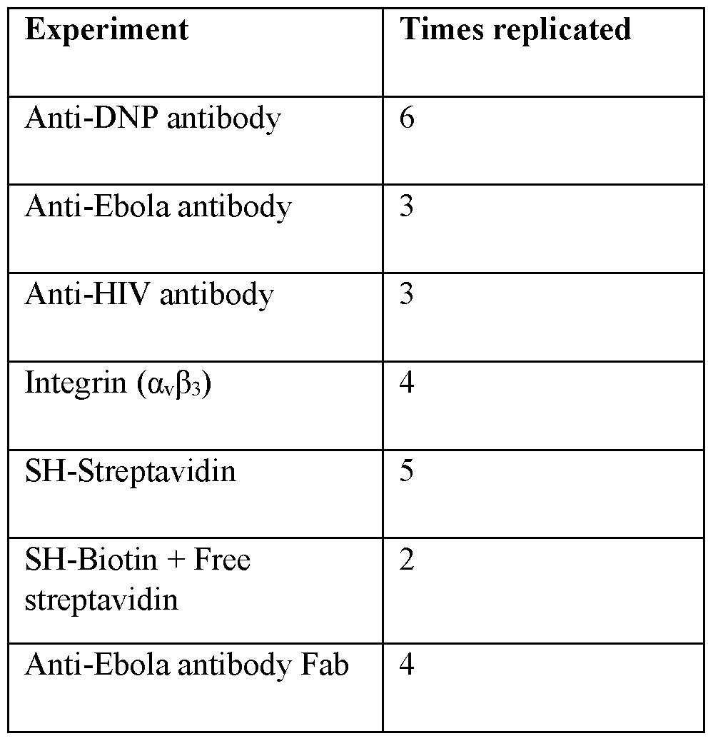
- bioelectronic circuit according to any of the above 4 to 6, wherein the protein is selected from the group consisting of IgE Anti-DNP, IgG Anti -HIV, IgG Anti -Ebola, Fab Anti -Ebola, a. ⁇ ⁇ b 2 Integrin, and streptavidin.
- bioelectronic circuit according to any of the above 4 to 6, further comprising wherein the protein is a polymerase, endonuclease, helicase or a proteosome.
- a bioelectronic circuit comprising:
- a bioelectronic circuit comprising: (a) a first and a second electrode,
- a bioelectronic circuit comprising:
- a bioelectronic circuit comprising: (a) a first and a second electrode,
- a bioelectronic circuit comprising:
- a bioelectronic circuit comprising:
- a method of preparing a bioelectronic circuit comprising:
- step (b) introducing a biotinylated protein to the streptavidin-electrode from step (a) to form a complex comprising the at least one electrode, the at least one streptavidin molecule and the biotinylated protein.
- a method for detecting the activity of a polymerase comprising introducing a solution of DNA template and nucleotriphosphates to the bioelectronic circuit of the above 4, wherein polymerized product indicates that the polymerase is active.
- a method for detecting the activity of protein comprising introducing a substrate of the protein to the bioelectronic circuit of the above 4 and detecting electrical changes.
- a system for electrical measurement of protein activity comprising:
- a bioelectronic circuit comprising:
- a bioelectronic circuit comprising:
- the present disclosure provides a bioelectronic circuit.
- the bioelectronic circuit comprises (a) at least one electrode, (b) at least one ligand that is specific for a protein, wherein said ligand is modified so that it attaches to the at least one electrode, and (c) at least one protein that binds the at least one ligand, thereby forming an electronic contact between the electrode and the protein.
- the bioelectronic circuit comprises one or two electrodes in direct contact with proteins. In the case where only one electrode is in contact with the proteins, the circuit is completed by means of ion currents that flow between a redox-active protein and a remote electrode.
- the bioelectronic circuit comprises one electrode. In another embodiment, bioelectronic circuit comprises two electrodes. In some aspects of this embodiment, the second electrode is not separated from the first electrode by an electrolyte.
- the at least one electrode comprises a noble metal.
- the at least one electrode comprises a noble metal selected from the group consisting of palladium, gold, and platinum.
- the at least one electrode is palladium.
- the at least one electrode is gold.
- the at least one electrode is platinum.
- the bioelectronic circuit comprises a ligand that is specific for a protein and is modified so that it attaches to the at least one electrode.
- the ligand can be modified to contain a thiol termination at one end for coupling to metals, as described by Zhang et al. 5
- ligands are peptide epitopes for antibodies comprising a cysteine residue at one end, recognition peptides (such as the RGD peptide for binding integrin comprising a cysteine) and small molecules to which proteins have been selected to bind (such as an IgE molecule that binds dintitrophenyl and comprising a thiol).
- Exemplary ligands that are specific for a protein and modified to attach to an electrode include, but are not limited to, HSCEECEE-dinitrophenol (target protein IgE Anti-DNP), CALDRWEKIRLR (target protein IgG Anti-HIV) (SEQ ID NO: 1), CHNTPVYKLDISEATQV (target protein IgG Anti-Ebola)
- the cysteine or thiol used for electrode attachment is in bold.
- Linear dimensions are from the RSCB PDB, either across a minor diameter or, for the antibodies, binding head to binding head: 1 IgE structure 4GRG, 2 IgG, structure 4NHH, Fab fragment structure 1YUH, 4 Integrin structure 1L5G, 5 streptavidin structure 1VWA.
- the bioelectronic circuit also comprises at least one protein that binds the at least one ligand.
- the protein can be any protein that can be expressed in a medium that allows for modification of the native protein sequence.
- any protein function can be incorporated into an electrical circuit so that changes induced by ligand or substrate binding, or enzyme activity can then be measured electrically.
- the bioelectronic circuit comprises (a) two palladium electrodes, (b) thiolated streptavidin attached to the palladium electrode, and (c) biotinylated polymerase, thereby forming an electronic contact between the electrode and the polymerase.
- bioelectronic circuit described below comprises palladium electrodes, thioloated streptavidin, and a biotinylated polymerase, this embodiment is illustrative of the present disclosure and the scope of the present disclosure is not limited to this one embodiment.
- thiolated streptavidin with an average of 2.5 thiols per tetramer was obtained from ProteinMods (Madison, Wisconsin).
- the streptavidin (31 in FIG. 3) was incubated in a 1 mM aqueous solution with a pair of noble metal (palladium) electrodes (the pair forming a nano-scale junction approximately 5 nm gap, 32, 33 in FIG. 3). Incubation overnight produced a dense coating of the streptavidin attached to the metal electrodes by means of a surface thiol (34).
- a bis-biotinylated f29 polymerase was constructed (35 in Fig 3).
- the Avitag peptide sequence, GLNDIFEAQKIEWHE (SEQ ID NO: 4) was inserted between residues Gi l l and K112, and a second Avitag peptide sequence was inserted between E279 and D280 in the f29 polymerase sequence (the exonuclease activity of which was deleted by mutating D12 and E14 to alanine).
- the Avitags were biotinylated using the BirA enzyme, as is well known in the art.
- the resulting molecule (35) therefore contained two biotin molecules (36 in FIG. 3).
- the biotinylated polymerase was incubated with the streptavidin functionalized junction for two hours (in 1 mM aqueous solution of f29 polymerase).
- the electrical properties of the bioelectronic circuit were measured by applying a voltage bias V across it (37) and recording the current (38) through the circuit. As noted by Zhang et al., 5 this bias must be less than 100 mV to avoid contact-generated noise, and 50 mV bias was used to collect the data shown here.
- a monobiotinylated f29 polymerase was prepared. To do this, the following sequence was added to the N-terminus of the WT (but exonuclease inactivated) enzyme: MGSSHHHHHHSSGLVPRGSGLNDIFEAQKIEWHEGASS (SEQ ID NO: 5), in which five histidines are a his-tag for purification of the protein and GLNDIFEAQKIEWHE (SEQ ID NO: 4) is the Avitag.
- FIG. 5 shows such distributions for the mono-biotinylated polymerase (51) and the bis-biotinylated polymerase (52).
- the bis-biotinylated molecule shows a new, high conductance feature (53) not present in the distribution measured for the mono-biotinylated molecule.
- This feature corresponds to about 4 nS conductance, a substantial increase over the highest conductance feature observed for the mono-biotinylated molecule (about 0.7 nS). This is a similar increase to that observed for molecules like antibodies connected by one or two specific contacts, as described by Zhang et al. 5 Note that these very high conductivities are obtained with the streptavidin molecules forming part of the circuit, showing that assemblies of several proteins in sequence maintain their quasi-metallic properties if they are properly connected.
- FIG. 6 shows electrical signals obtained from a bis-biotinylated polymerase molecule in its resting state 61 and its active state 62 where it is actively polymerizing a DNA template in the presence of dNTPs and Mg.
- current data were recorded for about 90 s after an electrode was moved into contact with the complex.
- Formation of the streptavidin- f29 polymerase contact takes about 20 s, after which the current (at 50 mV bias) jumps from zero to about 60 pA.
- the control molecule 61 the current remains fairly quiet and constant for the remainder of the run.
- bursts of noise 63 are observed, each lasting for a few seconds.
- bursts themselves consist of sub-bursts (65), the duration and spacing of which are consistent with the interpretation that each sub-burst (65) signals the incorporation of a single nucleotide (given the known kinetics of f29 polymerase). This illustrates the use of the current invention in building circuits that can monitor enzyme activity electrically.
- the Avitag should be placed as close as possible to tyrosines, tryptophans or histidines that are near the surface of the protein.
- the bioelectronic circuit comprises (a) two palladium electrodes, (b) thiolated biotin attached to the palladium electrode, and (c) streptavidin. This embodiment allows for a uniform coating of small molecules on the electrode.
- biotinylated cystamine was used as the thiolated biotin.
- N,N’- bisbiotinyl-cystamine 11 (chemical structure shown in FIG. 1) was synthesized as described in the Examples. Because of the S-S linkage (12 in FIG. 1), 11 is stable in oxidizing environments (like air). It can be reduced to the monothiol 20 (chemical shown in FIG. 2) in the presence of a strong reducing agent. Reducing agents are known in the art and any can be used.
- the reducing agent is an immobilized TCEP (Tris[2-carboxyethyl] phosphine hydrochloride) disulfide reducing gel from Thermo Scientific (cat # 77712).
- electrodes are functionalized with thio-biotin, and the junction is then exposed to wild type (i.e., lacking surface thiols) streptavidin.
- wild type streptavidin i.e., lacking surface thiols
- the result is a strongly conducting bridge. This is illustrated in FIG. 7.
- the gap is bridged by a thiolated streptavidin molecule which has been incubated with biotin (this is because biotin binding changes the conductance of streptavidin as described by Zhang et al. 5 so it is necessary to compare biotin-bound streptavidin molecules to see the intrinsic contact differences in these experiments).
- the electrodes are first functionalized with the mono-thiolated biotin (20) and then wild type streptavidin is introduced to bind and complete the circuit.
- the current distribution for the thiolated streptavidin (as biotin bound) directly attached to the electrodes is shown in 73.
- the distribution for the wild type streptavidin captured between biotinylated electrodes is shown in 74.
- a new, high conductance feature is observed at nearly 7nS (75) in the case where the thio-biotin molecule (20) is used to attach the streptavidin to the electrodes.
- connection via a specifically-binding ligand (biotin) that is, itself, attached to the electrode via a thiol can form a better contact than a direct attachment of the protein itself via a surface thiol on the protein.
- the protein contains one contact for a ligand. In the embodiments described in the following paragraph, the protein contains a second contact for a ligand.
- the integrin molecule listed in Table 1 has one binding site for a small ligand that makes an excellent electrical contact (the cyclic RGD peptide incorporating a cysteine as listed in Table 1). But contact to a second point cannot be made via another ligand, because this integrin only has one RGD binding site.
- a well-defined circuit can be completed by incorporating an Avitag sequence into a region near the N terminus of the integrin, so that now it has two specific binding sites: (1) the RGD peptide binding site and (2) the biotin binding site.
- Heterogeneous contacts like this have the advantage that the protein can be oriented in an assembly by exploiting the selective attachment now incorporated into the protein.
- one electrode might be functionalized with the streptavidin, and a second with the peptide (i.e., cyclic RGD), so that the modified protein would then always be bound in a well-defined orientation with respect to both electrodes.
- the same technology enables sequential assembly of protein circuits. This is illustrated with the protein“AND” gate shown in FIG. 8.
- the pair comprise a chemical AND gate because the high conductance state is only obtained when both ligand A and ligand B are present.
- the first electrode, 84 is modified with the thio-biotin molecule 86 that binds a streptavidin molecule 87. This in turn binds protein A 81 that has been modified so as to have incorporated two biotinylated Avitag sequences 83.
- additional useful building blocks can be created by linking one ligand to another. For example, by concatenating a peptide ligand (such as one of those shown in Table 1) to a biotin molecule, so that a first protein with a specific binding site to the peptide could be linked to streptavidin, for example, for subsequent incorporation into a circuit via the remaining unoccupied biotin binding sites on the streptavidin.
- a peptide ligand such as one of those shown in Table 1
- streptavidin for example, for subsequent incorporation into a circuit via the remaining unoccupied biotin binding sites on the streptavidin.
- the first consideration is that the incorporated sequence should not consist of short repeats, as this complicates cloning.
- the corresponding DNA template is shown in FIG. 9A, which also shows the dimer that can be formed between primer sequences.
- FIG. 9B shows the sequence of the resulting plasmid with the products of the undesired primer dimers labeled.
- the second consideration is that the isoelectric point of the new protein should not be altered
- the residues in the inserted linker should be chosen to be neutral or nearly so.
- This is illustrated by the synthesis of a phi29 polymerase containing two Avitags for wiring into a circuit.
- the flexible linker was placed next to the Avitag sequence located near the N terminus.
- the flexible linker (circled, 103) has the sequence GDSTDGTSDGSS (SEQ ID NO: 7) with the result that the protein product has a calculated pi of 7.25. This small shift from the pi of the native protein (which is a pi of about 8) is enough to cause misfolding resulting in the protein appearing as a shorter product 105 in a gel 106.
- the third consideration arises when two identical sequences (i.e., two Avitag sequences) are to be inserted into the same clone expression system, as the corresponding repeated DNA sequence results in primer- dimers.
- the cloning proceeds in two steps. A clone with one Avitag sequence is first produced, and then a second clone is generated from this first clone with the second Avitag sequence inserted.
- FIG. 11 shows the reference conductance distribution 1101 for the two-Avitag polymerase previously shown as 52 in FIG. 5 (lacking a flexible linker sequence).
- the high conductance feature owing to binding the two biotinylated sites is labeled 1103.
- 1102 shows the conductance distribution for the phi29 incorporating a flexible linker (protein sequence 102 in FIG. 10). The high conductance feature is preserved (1104) showing that flexible peptide linkers can be incorporated while maintaining the quasi- metallic state of the protein.
- FIG. 12 shows an“OR” gate based on the same assembly principles (the numbered components are as described for FIG. 8). This will enter the high conductance state if either ligand A or ligand B is present.
- FIG. 13 where, again, numbering is as in FIG. 8.
- a third protein“C” (1300) is attached to the junction of protein A and protein B at an unoccupied site of the coupling streptavidin 87.
- protein C is an electrochemically active protein that changes its oxidation state in the presence of oxidizing molecules, for example, then the change of charge on protein C will modulate electron transport through the A-B chain.
- the“A” AND“B” function can give rise to a third state that depends on the electronic state of“C”.
- protein D 1400 is a redox active protein (for, example, glucose oxidase) immersed in an electrolyte 1401 containing a redox couple 1402, 1403 (for example, oxidized and reduced glucose) with a second (remote) electrode 1404 in contact with the electrolyte 1401 also, and connected to the first electrode 84 with a means for applying a voltage bias 1405 and a means for sensing the current 1406 that flows between the first electrode 84 and the second electrode 1404.
- a redox active protein for, example, glucose oxidase
- 1403 for example, oxidized and reduced glucose
- second (remote) electrode 1404 in contact with the electrolyte 1401 also, and connected to the first electrode 84 with a means for applying a voltage bias 1405 and a means for sensing the current 1406 that flows between the first electrode 84 and the second electrode 1404.
- the bioelectronic circuit of FIG 3 requires direct attachment of the modified coupling proteins to the electrodes.
- coupling is more efficient if it is made via a small ligand attached to the electrode using an unmodified coupling protein. This has the advantage that the electrodes can be functionalized with a small ligand with which it is easier to obtain uniform coverage.
- FIG. 15 shows a first electrode 1532 modified with the thiobiotin of FIG. 2 1534 binding and unmodified streptavidin 1531 that in turn binds the protein 1535 that has been biotinylated at the tow sites 1536. Similar functionalization completes the coupling to the second electrode 1533.
- the size of the gap over which protein conduction is monitored can be increased substantially at very little cost in conductivity by forming a daisy-chain of coupled proteins with each electrode as shown in FIG. 16.
- a second coupling protein 1602 is added into the circuit, coupled to the first 1531 by means of a bivalent linker 1601 such as the bis-biotin shown in FIG. 1.
- RGD peptide (cyclo(Arg-Gly-Asp-D-Phe-Cys)) was purchased from Peptides International (Louisville, Kentucky). Peptide ligands for the anti -HIV antibody and the anti -Ebola antibody were synthesized by CPC Scientific (Sunnyvale, California) with a purity >95%. DNP and biotin disulfides were synthesized in our lab (SI Appendix Figs. S10 and SI 3) and reduced for 2 h before use by an immobilized TCEP (Tris[2-carboxyethyl] phosphine hydrochloride) disulfide reducing gel from Thermo Scientific (cat # 77712) following the manufacturer’s instructions.
- TCEP Tris[2-carboxyethyl] phosphine hydrochloride
- Anti-DNP antibody mouse monoclonal IgE antibody
- wild-type streptavidin and all other chemicals were purchased from Sigma Aldrich (Saint Louis, Missouri).
- Anti- HIV antibody Anti -HIV 1 pl7 antibody [32/1.24.89]
- Anti-Ebola antibody was cultured from plants as described below. Binding affinities of all the three antibodies were measured by surface plasmon resonance (SPR). Thiolated streptavidin with an average of 2.5 thiols per tetramer was from ProteinMods (Madison, Wisconsin).
- Ag/AgCl reference electrodes salt-bridged by 3 M KC1 or 10 mM KC1 were prepared as described previously.
- the anti-Ebola antibody and the corresponding monomeric Fab fragment were prepared and purified as described in the Example 7.
- Cystamine dihydrochloride (60 mg, 0.27 mmol) was added into DMF (2mL), followed by the addition of triethyl amine (0.44 mL, 3.19 mmol). The mixture was stirred for 30 min, to which biotin NHS ester (0.27g, 0.80 mmol) was added, and stirred at room temperature for 16 h. TLC indicted that cystamine was consumed and a product produced with an R f value of 0.63 in 20% methanol in DCM. The mixture was co-evaporated with dichloromethane until most of DMF and TEA was removed.
- Compound 20 was produced by exposing N,N’-bis-biotinyl-cystamine 11 for 2 h (immediately before use in devices) to an immobilized TCEP (Tris[2-carboxyethyl] phosphine hydrochloride) disulfide reducing gel from Thermo Scientific (cat # 77712) following the manufacturer’s instructions.
- TCEP Tris[2-carboxyethyl] phosphine hydrochloride
- Palladium substrates for STM measurement were prepared by evaporating a 200 nm palladium film onto a silicon wafer using an electron-beam evaporator (Lesker PVD 75), with a 10 nm titanium adhesion layer.
- the substrates were treated with a hydrogen flame immediately before functionalizing and then immersed in solutions of thiolated DNP, biotin, streptavidin or peptides containing a cysteine residue, overnight.
- Substrate functionalization with small ligands was characterized by Fourier transform infrared (FTIR) spectroscopy (Fig. S9) and ellipsometry. Coverage of the substrate was monitored by STM and AFM imaging.
- FTIR Fourier transform infrared
- STM probes were etched from a 0.25mm Pd wire (California Fine Wires) by an AC electrochemical method. To avoid current leakage, probes were insulated with high-density polyethylene following the method described earlier for gold probes. M. Tuchband et ah, Rev Sci Instrum 83, 015102 (2012). Each probe was tested by STM in 1 mM PB buffer at +0.5 V bias to ensure the leakage current was ⁇ lpA. For functionalization, the probe was immersed in ligand solutions for 4 h or overnight. After that, it was taken out, rinsed with water, gently blown dry with nitrogen gas, and used immediately. Further details of the STM measurements are given in Example 4.
- MCE 2-mercaptoethanol
- Pd substrates were cut into 0.5 cm x 4.0 cm in size and used as the working electrode, with an active cell area of about 0.5 cm x 1.0 cm.
- the substrate was treated with a hydrogen flame before functionalization.
- Cyclic voltammetry was performed on a potentiostat (Model AFCBP1, Pine Instruments), using a Pt wire as the counter electrode and an Ag/AgCl (3M KC1) as the reference electrode.
- the sweep range is from -0.5 V to +0.5 V, with a sweep rate of 10 mV/s unless stated otherwise.
- Example 7 Expression and purification of anti-Ebola (EBOV) mAb 6D8 from Nicotiana benthamiana plants
- 6D8 mAb was isolated and purified to > 95% homogeneity from N. benthamiana leaves by protein A affinity chromatography. Fulton, A. el al. , J ChromatogrA 1389, 128-132, doi: 10.1016/j.chroma.2015.02.013 (2015).
- Monomeric Fab fragments were prepared from 6D8 by using the Pierce Fab Preparation Kit (Thermo Scientific) according to the manufacturer’s instructions (Thermos Scientific Pub. No. MAN0011651). Briefly, purified 6D8 was first incubated with papain immobilized to agarose beads at 37°C for 6-12 hr. The digested mAb mixture was then recovered by centrifugation at 5000xg for 1 min and separated on a protein A chromatography column. The Fab fragment was recovered in the flow through fraction, while the Fc fragment and undigested mAb were trapped in the protein A column. The successful production of monomeric Fab was verified by SDS-PAGE analysis under both reducing and non-reducing conditions.
- each IV trace can be characterized by a single conductance value, G.
- Measured distributions of G follow the log-normal distribution usually observed in single molecule measurements (data not shown).
- the distributions are similar to distributions of current values obtained by recording current vs. time at a fixed gap and bias (data not shown) so the distribution was ascribed to different kinds of contact between the electrodes and the molecule.
- Bare metal electrodes were used to capture the thiolated streptavidin, where the thiol mediated contacts displace the contamination on the electrode surfaces, (11) forming direct metal- molecule contacts.
- the integrin was captured by the cyclic RGD peptide at only one of the two electrodes, and no signals were observed unless both electrodes were functionalized. Functionalization with peptides allows for non-specific contacts with hydrophilic sites on the protein at the electrode that is not specifically coupled.
- the three antibodies yielded two conductance peaks (-0.3 nS and -2 nS), suggesting two binding modes: NS-S as for the integrin, and the desired S-S when both antigen-binding sites bind specifically (data not shown).
- the contact point changes over the (-minute) course of a measurement, a reflection of the angstrom-scale change in the position of the STM probe. It is these various contact geometries that generate the overall shape of the conductance distributions (data not shown). Since the distributions retain the same peak positions and shapes at the different gap sizes, the data show no indications of proteins being“squeezed” at the smaller gap sizes.
- FIG. 7A Biotin complexation in a thiolated-streptavidin sample changes the conductance distribution significantly (FIG. 7A).
- a streptavidin molecule has four biotin binding sites, (16) so that the unthiolated apo-protein can be crosslinked by two biotins.
- a thiolated biotin was synthesized and functionalized both the probe and substrate with it (FIG. 7B), subsequently flowing apo- streptavidin into the sample cell.
- a tunneling conductance can be estimated from G ⁇ Go exp (-bc) where Go is 77pS and b ⁇ lA 1 . (24) For a small protein with x ⁇ 4 nm, this yields G ⁇ 10 21 S, 12 orders of magnitude smaller than observed. To account for the observation of nS conductance over 10 nm distances would require a b ⁇ 0. lA 1 .
- Similar transport via readily oxidized amino acids has been observed in peptides.
- this 0.25V barrier is similar to the charge injection barrier deduced from the redox potentials of the amino acids, as discussed above. If the charge injection rate was limited by thermally activated hopping over a 0.22 to 0.47V barrier, and it is this rate that determines the conductance, then we would expect to observe a conductance of « G exp where 0.22 ⁇ V ⁇ 0.47 volts, yielding from 12 nS to 0.5 pS, a range which encompasses the values reported here.
Landscapes
- Chemical & Material Sciences (AREA)
- Life Sciences & Earth Sciences (AREA)
- Health & Medical Sciences (AREA)
- Organic Chemistry (AREA)
- Engineering & Computer Science (AREA)
- Proteomics, Peptides & Aminoacids (AREA)
- Zoology (AREA)
- Wood Science & Technology (AREA)
- Immunology (AREA)
- Molecular Biology (AREA)
- Physics & Mathematics (AREA)
- Analytical Chemistry (AREA)
- General Health & Medical Sciences (AREA)
- Biochemistry (AREA)
- Biophysics (AREA)
- Microbiology (AREA)
- Biotechnology (AREA)
- Bioinformatics & Cheminformatics (AREA)
- General Engineering & Computer Science (AREA)
- Genetics & Genomics (AREA)
- Hematology (AREA)
- Biomedical Technology (AREA)
- Urology & Nephrology (AREA)
- Pathology (AREA)
- General Physics & Mathematics (AREA)
- Medicinal Chemistry (AREA)
- Food Science & Technology (AREA)
- Cell Biology (AREA)
- Bioinformatics & Computational Biology (AREA)
- Chemical Kinetics & Catalysis (AREA)
- Electrochemistry (AREA)
- Measuring Or Testing Involving Enzymes Or Micro-Organisms (AREA)
- Investigating Or Analyzing Materials By The Use Of Electric Means (AREA)
- Measuring And Recording Apparatus For Diagnosis (AREA)
- Peptides Or Proteins (AREA)
- Light Receiving Elements (AREA)
- Inorganic Insulating Materials (AREA)
- Apparatus Associated With Microorganisms And Enzymes (AREA)
Abstract
Description


Claims
Priority Applications (12)
| Application Number | Priority Date | Filing Date | Title |
|---|---|---|---|
| EP23188136.8A EP4269604A3 (en) | 2019-01-30 | 2020-01-30 | Bioelectronic circuits, systems and methods for preparing and using them |
| AU2020214334A AU2020214334A1 (en) | 2019-01-30 | 2020-01-30 | Bioelectronic circuits, systems and methods for preparing and using them |
| EP20749683.7A EP3918329A4 (en) | 2019-01-30 | 2020-01-30 | BIOELECTRONIC CIRCUITS, SYSTEMS AND METHODS FOR THEIR MANUFACTURE AND USE |
| MX2021009150A MX2021009150A (en) | 2019-01-30 | 2020-01-30 | Bioelectronic circuits, systems and methods for preparing and using them. |
| KR1020217027199A KR20210126028A (en) | 2019-01-30 | 2020-01-30 | Bioelectronic circuits, systems and methods for making and using them |
| SG11202107947RA SG11202107947RA (en) | 2019-01-30 | 2020-01-30 | Bioelectronic circuits, systems and methods for preparing and using them |
| US17/426,893 US12351855B2 (en) | 2019-01-30 | 2020-01-30 | Bioelectronic circuits, systems and methods for preparing and using them |
| CA3128358A CA3128358A1 (en) | 2019-01-30 | 2020-01-30 | Bioelectronic circuits, systems and methods for preparing and using them |
| JP2021543394A JP2022523691A (en) | 2019-01-30 | 2020-01-30 | Bioelectric circuits, systems and methods for manufacturing and using them |
| CN202080017643.0A CN113874728B (en) | 2019-01-30 | 2020-01-30 | Bioelectronic circuits, systems, and methods of making and using the same |
| BR112021014800A BR112021014800A2 (en) | 2019-01-30 | 2020-01-30 | Bioelectronic circuits, systems and methods for their preparation |
| IL285075A IL285075A (en) | 2019-01-30 | 2021-07-22 | Bioelectronic circuits, systems and methods for preparing and using them |
Applications Claiming Priority (2)
| Application Number | Priority Date | Filing Date | Title |
|---|---|---|---|
| US201962799006P | 2019-01-30 | 2019-01-30 | |
| US62/799,006 | 2019-01-30 |
Publications (3)
| Publication Number | Publication Date |
|---|---|
| WO2020160300A2 true WO2020160300A2 (en) | 2020-08-06 |
| WO2020160300A3 WO2020160300A3 (en) | 2020-09-10 |
| WO2020160300A9 WO2020160300A9 (en) | 2020-10-29 |
Family
ID=71841943
Family Applications (1)
| Application Number | Title | Priority Date | Filing Date |
|---|---|---|---|
| PCT/US2020/015931 Ceased WO2020160300A2 (en) | 2019-01-30 | 2020-01-30 | Bioelectronic circuits, systems and methods for preparing and using them |
Country Status (12)
| Country | Link |
|---|---|
| US (1) | US12351855B2 (en) |
| EP (2) | EP4269604A3 (en) |
| JP (1) | JP2022523691A (en) |
| KR (1) | KR20210126028A (en) |
| CN (1) | CN113874728B (en) |
| AU (1) | AU2020214334A1 (en) |
| BR (1) | BR112021014800A2 (en) |
| CA (1) | CA3128358A1 (en) |
| IL (1) | IL285075A (en) |
| MX (1) | MX2021009150A (en) |
| SG (1) | SG11202107947RA (en) |
| WO (1) | WO2020160300A2 (en) |
Cited By (10)
| Publication number | Priority date | Publication date | Assignee | Title |
|---|---|---|---|---|
| WO2022133113A1 (en) * | 2020-12-18 | 2022-06-23 | Arizona Board Of Regents On Behalf Of Arizona State University | Method for manufacturing protein bioelectronic devices |
| US20220389502A1 (en) * | 2021-06-07 | 2022-12-08 | Arizona Board Of Regents On Behalf Of Arizona State University | Methods for sequencing biopolymers |
| US11808755B2 (en) | 2018-05-17 | 2023-11-07 | Recognition AnalytiX, Inc. | Device, system and method for direct electrical measurement of enzyme activity |
| US11913070B2 (en) | 2020-02-28 | 2024-02-27 | Arizona Board Of Regents On Behalf Of Arizona State University | Methods for sequencing biopolymers |
| US12031981B2 (en) | 2018-05-09 | 2024-07-09 | Arizona Board Of Regents On Behalf Of Arizona State University | Method for electronic detection and quantification of antibodies |
| US12276653B2 (en) | 2020-05-29 | 2025-04-15 | Arizona Board Of Regents On Behalf Of Arizona State University | Bioelectronic devices with programmable adaptors |
| US12298300B2 (en) | 2020-04-17 | 2025-05-13 | Arizona Board Of Regents On Behalf Of Arizona State University | Single-molecule electronic sequence detector and methods of use |
| US12351855B2 (en) | 2019-01-30 | 2025-07-08 | Arizona Board Of Regents On Behalf Of Arizona State University | Bioelectronic circuits, systems and methods for preparing and using them |
| EP4267950A4 (en) * | 2020-12-22 | 2025-07-30 | Recognition Analytix Inc | DEVICES, METHODS AND SYSTEMS FOR MANIPULATING PROTEINS IN BIOELECTRONIC CIRCUITS |
| US12509720B2 (en) | 2020-04-30 | 2025-12-30 | Arizona Board Of Regents On Behalf Of Arizona State University | Methods for sequencing biopolymers |
Families Citing this family (1)
| Publication number | Priority date | Publication date | Assignee | Title |
|---|---|---|---|---|
| WO2025080785A1 (en) * | 2023-10-10 | 2025-04-17 | Arizona Board Of Regents On Behalf Of Arizona State University | Methods and molecular constructs for incorporating molecules into electrical circuits |
Family Cites Families (130)
| Publication number | Priority date | Publication date | Assignee | Title |
|---|---|---|---|---|
| JPH0719927B2 (en) | 1988-03-30 | 1995-03-06 | 工業技術院長 | Photoelectric conversion device using avidin-biotin system and manufacturing method thereof |
| US5198543A (en) | 1989-03-24 | 1993-03-30 | Consejo Superior Investigaciones Cientificas | PHI29 DNA polymerase |
| US6391558B1 (en) | 1997-03-18 | 2002-05-21 | Andcare, Inc. | Electrochemical detection of nucleic acid sequences |
| US6758961B1 (en) | 1997-12-17 | 2004-07-06 | Ecole Polytechnique Federale De Lausanne | Positioning and electrophysiological characterization of individual cells and reconstituted membrane systems on microstructured carriers |
| US7244349B2 (en) | 1997-12-17 | 2007-07-17 | Molecular Devices Corporation | Multiaperture sample positioning and analysis system |
| IL124322A (en) | 1998-05-04 | 2002-05-23 | Technion Res & Dev Foundation | Detection of an entity in a sample |
| RU2161653C2 (en) * | 1998-08-24 | 2001-01-10 | ФАРМАКОВСКИЙ Дмитрий Александрович | Method of quantitative electrochemical analysis of biological molecules |
| DE19960076C2 (en) | 1999-12-13 | 2002-12-05 | November Ag Molekulare Medizin | Method and device for the detection and quantification of biomolecules |
| US7015047B2 (en) | 2001-01-26 | 2006-03-21 | Aviva Biosciences Corporation | Microdevices having a preferential axis of magnetization and uses thereof |
| US6824974B2 (en) | 2001-06-11 | 2004-11-30 | Genorx, Inc. | Electronic detection of biological molecules using thin layers |
| AU2002365119A1 (en) | 2001-07-30 | 2003-09-04 | Meso Scale Technologies, Llc. | Assay electrodes having immobilized lipid/protein layers and methods of making and using the same |
| DE60237373D1 (en) | 2001-08-07 | 2010-09-30 | Medestea Internaz S R L | ISOLATED POLYPEPTIDES BASED ON THE NEUTRALIZING EPITOPS OF P17 PROTEIN OF HIV SUITABLE AS VACCINES AND NEUTRALIZING ANTI-P17 ANTIBODIES SPECIFICALLY RECOGNIZING SPECIFIC EPITOP |
| US7632671B2 (en) | 2001-11-29 | 2009-12-15 | Sun-Wing Tong | Molecular detection and assay by electrobiochip micro-array |
| DE10247679A1 (en) | 2002-10-12 | 2004-04-22 | Fujitsu Ltd., Kawasaki | Semiconductor body structure, as a biosensor, has two thick layers of one material separated by a thin different intermediate layer forming a nano gap, with organic wire structures as the contacts |
| EP1654533B1 (en) | 2003-08-06 | 2016-03-23 | Bridger Technologies, Inc. | Bridged element for detection of a target substance |
| US7462452B2 (en) | 2004-04-30 | 2008-12-09 | Pacific Biosciences Of California, Inc. | Field-switch sequencing |
| US7385295B2 (en) | 2004-06-24 | 2008-06-10 | California Institute Of Technology | Fabrication of nano-gap electrode arrays by the construction and selective chemical etching of nano-crosswire stacks |
| US7785785B2 (en) | 2004-11-12 | 2010-08-31 | The Board Of Trustees Of The Leland Stanford Junior University | Charge perturbation detection system for DNA and other molecules |
| US20070292855A1 (en) | 2005-08-19 | 2007-12-20 | Intel Corporation | Method and CMOS-based device to analyze molecules and nanomaterials based on the electrical readout of specific binding events on functionalized electrodes |
| US20070231794A1 (en) | 2005-09-21 | 2007-10-04 | Combimatrix Corporation | Process to detect binding events on an electrode microarray using enzymes |
| US8855955B2 (en) | 2005-09-29 | 2014-10-07 | Custom Array, Inc. | Process and apparatus for measuring binding events on a microarray of electrodes |
| KR100849384B1 (en) | 2005-10-21 | 2008-07-31 | 한국생명공학연구원 | A method for fabricating nanogap and nanogap sensor |
| WO2007102839A2 (en) | 2005-10-27 | 2007-09-13 | Applera Corporation | Optoelectronic separation of biomolecules |
| WO2007120312A2 (en) | 2005-12-15 | 2007-10-25 | The Trustees Of Columbia University In The City Of New York | Sensing devices from molecular electronic devices |
| US7777505B2 (en) | 2006-05-05 | 2010-08-17 | University Of Utah Research Foundation | Nanopore platforms for ion channel recordings and single molecule detection and analysis |
| US8394590B2 (en) | 2006-08-02 | 2013-03-12 | California Institute Of Technology | Capture agents and related methods and systems for detecting and/or sorting targets |
| WO2008124706A2 (en) | 2007-04-06 | 2008-10-16 | Arizona Board Of Regents Acting For And On Behalf Of Arizona State University | Devices and methods for target molecule characterization |
| AT505495A1 (en) | 2007-07-04 | 2009-01-15 | Arc Austrian Res Centers Gmbh | METHOD FOR IDENTIFYING AND QUANTIFYING ORGANIC AND BIOCHEMICAL SUBSTANCES |
| US8183648B2 (en) | 2008-01-25 | 2012-05-22 | Ut-Battelle, Llc | Nanoscopic electrode molecular probes |
| US8865179B2 (en) | 2008-01-26 | 2014-10-21 | Swey-Shen Alexchen | Aptameric IgE peptides in a protein scaffold as an allergy vaccine |
| WO2009117517A2 (en) | 2008-03-18 | 2009-09-24 | Arizona Board Of Regents Acting For And On Behalf Of Arizona State University | Nanopore and carbon nanotube based dna sequencer |
| US8628649B2 (en) | 2008-03-18 | 2014-01-14 | Arizona Board Of Regents Acting For And On Behalf Of Arizona State University | Nanopore and carbon nanotube based DNA sequencer and a serial recognition sequencer |
| US8753893B2 (en) | 2008-06-19 | 2014-06-17 | Ben H. Liu | Multi-dimensional fluid sensors and related detectors and methods |
| EP2304444A4 (en) | 2008-06-19 | 2012-04-25 | Agency Science Tech & Res | MODULATORS OF THE INTERACTION BETWEEN STAT3 AND SP1 |
| US8968540B2 (en) | 2008-10-06 | 2015-03-03 | Arizona Board Of Regents, A Body Corporate Of The State Of Arizona Acting For And On Behalf Of Arizona State University | Trans-base tunnel reader for sequencing |
| US8669079B2 (en) | 2008-11-12 | 2014-03-11 | Cara Therapeutics, Inc. | Methods for genetic analysis of textiles made of Gossypium barbadense and Gossypium hirsutum cotton |
| US8715981B2 (en) | 2009-01-27 | 2014-05-06 | Purdue Research Foundation | Electrochemical biosensor |
| US20100219085A1 (en) | 2009-02-27 | 2010-09-02 | Edwards Lifesciences Corporation | Analyte Sensor Offset Normalization |
| US9376713B2 (en) | 2009-09-23 | 2016-06-28 | The Board Of Trustees Of The University Of Illinois | Label free detection of nucleic acid amplification |
| JP5838474B2 (en) | 2010-02-02 | 2016-01-06 | アリゾナ ボード オブ リージェンツ オン ビハーフ オブ アリゾナ ステート ユニバーシティ | Controlled tunnel gap device for determining polymer alignment |
| JP4963000B2 (en) | 2010-06-15 | 2012-06-27 | 株式会社第一興商 | Rapid and sensitive molecular detection and quantification method using power-generating enzyme by charge measurement, and detection unit and apparatus for use in the method |
| WO2011159942A1 (en) | 2010-06-18 | 2011-12-22 | Illumina, Inc. | Conformational probes and methods for sequencing nucleic acids |
| SG189157A1 (en) | 2010-10-15 | 2013-05-31 | Univ Nanyang Tech | A memristor comprising a protein and a method of manufacturing thereof |
| US20130123121A1 (en) | 2010-11-22 | 2013-05-16 | The University Of Chicago | Methods and/or Use of Oligonucleotide-Bead Conjugates for Assays and Detections |
| US9926596B2 (en) | 2011-05-27 | 2018-03-27 | Genapsys, Inc. | Systems and methods for genetic and biological analysis |
| WO2013038272A2 (en) | 2011-09-13 | 2013-03-21 | Uti Limited Partnership | Streptavidin mutein exhibiting reversible binding for biotin and streptavidin binding peptide tagged proteins |
| US9347900B2 (en) | 2011-10-14 | 2016-05-24 | Pacific Biosciences Of California, Inc. | Real-time redox sequencing |
| JP6082996B2 (en) | 2011-11-22 | 2017-02-22 | パナソニックIpマネジメント株式会社 | Biomolecule single molecule detection method, single molecule detection apparatus, and disease marker inspection apparatus |
| US10093975B2 (en) | 2011-12-01 | 2018-10-09 | Genapsys, Inc. | Systems and methods for high efficiency electronic sequencing and detection |
| WO2013116509A1 (en) | 2012-02-01 | 2013-08-08 | Arizona Board Of Regents Acting For And On Behalf Of Arizona State University | Systems, apparatuses and methods for reading an amino acid sequence |
| WO2013126906A1 (en) | 2012-02-24 | 2013-08-29 | University Of Washington Through Its Center For Commercialization | Method and system for concentrating particles from a solution |
| US20150142327A1 (en) | 2012-03-28 | 2015-05-21 | Arizona Board Of Regents On Behalf Of Arizona State University | Method for improving the accuracy of chemical identification in a recognition-tunneling junction |
| US20130302901A1 (en) | 2012-04-04 | 2013-11-14 | Stuart Lindsay | Electrodes for Sensing Chemical Composition |
| WO2013154999A2 (en) | 2012-04-09 | 2013-10-17 | The Trustees Of Columbia University In The City Of New York | Method of preparation of nanopore and uses thereof |
| WO2013180819A1 (en) | 2012-06-01 | 2013-12-05 | Arizona Board Of Regents Acting For And On Behalf Of Arizona State University | System, method and device for analysis of carbohydrates |
| US20150204873A1 (en) | 2012-06-18 | 2015-07-23 | Electonic Biosciences, Inc. | Cell-free assay device and methods of use |
| EP3674412A1 (en) | 2012-06-20 | 2020-07-01 | The Trustees of Columbia University in the City of New York | Nucleic acid sequencing by nanopore detection of tag molecules |
| TWI492384B (en) | 2012-08-17 | 2015-07-11 | 國立交通大學 | Protein crystal device |
| EP2900830B1 (en) | 2012-09-27 | 2016-11-09 | Technische Universiteit Eindhoven | Switchable reporter enzymes for homogenous antibody detection |
| EP2906720A4 (en) | 2012-10-10 | 2016-06-01 | Univ Arizona | SYSTEMS AND DEVICES FOR DETECTING MOLECULES AND METHOD FOR THE PRODUCTION THEREOF |
| US9605309B2 (en) | 2012-11-09 | 2017-03-28 | Genia Technologies, Inc. | Nucleic acid sequencing using tags |
| EP2965073B1 (en) | 2013-03-05 | 2018-10-31 | Arizona Board Of Regents Acting For And On Behalf Of State Arizona University | Translocation of a polymer through a nanopore |
| EP2971180A4 (en) | 2013-03-13 | 2016-11-23 | Univ Arizona State | SYSTEMS, DEVICES AND METHODS FOR TRANSLOCATION CONTROL |
| EP2994544B1 (en) | 2013-05-06 | 2019-10-02 | Pacific Biosciences Of California, Inc. | Real-time electronic sequencing |
| US9766248B2 (en) | 2013-05-23 | 2017-09-19 | Arizona Board of Regents of behalf of Arizona State University | Chemistry, systems and methods of translocation of a polymer through a nanopore |
| WO2014190322A2 (en) | 2013-05-24 | 2014-11-27 | Quantapore, Inc. | Nanopore-based nucleic acid analysis with mixed fret detection |
| US20160108002A1 (en) | 2013-05-30 | 2016-04-21 | Arizona Board Of Regents Acting For And On Behalf Of Arizona State University | Universal reader molecule for recognition tunneling |
| TW201502276A (en) | 2013-07-09 | 2015-01-16 | Univ Nat Chiao Tung | Sequencing method for label-free single molecular nucleic acid |
| WO2015065985A1 (en) | 2013-10-31 | 2015-05-07 | Arizona Board Of Regents On Behalf Of Arizona State University | Chemical reagents for attaching affinity molecules on surfaces |
| WO2015126963A1 (en) | 2014-02-18 | 2015-08-27 | Arizona Board Of Regents Acting For And On Behalf Of Arizona State University | A three arm y-shaped bisbiotin ligand |
| WO2015127387A1 (en) | 2014-02-21 | 2015-08-27 | Northeastern University | Fluorescence-based analysis of biopolymers using nanopores |
| US20170016852A1 (en) | 2014-02-25 | 2017-01-19 | Arizona Board Of Regents Acting For And On Behalf Of Arizona State University | Methods, apparatuses, and systems for stabilizing nano-electronic devices in contact with solutions |
| WO2015131073A1 (en) | 2014-02-27 | 2015-09-03 | Arizona Board Of Regents Acting For And On Behalf Of Arizona State University | Triazole-based reader molecules and methods for synthesizing and use thereof |
| US10145846B2 (en) | 2014-04-16 | 2018-12-04 | Arizona Board Of Regents On Behalf Of Arizona State University | Digital protein sensing chip and methods for detection of low concentrations of molecules |
| US10287257B2 (en) | 2014-05-07 | 2019-05-14 | Arizona Board Of Regents On Behalf Of Arizona State University | Linker molecule for multiplex recognition by atomic force microscopy (AFM) |
| WO2015170784A1 (en) | 2014-05-08 | 2015-11-12 | Osaka University | Nanogap electrodes with dissimilar materials |
| CN106687574B (en) | 2014-06-03 | 2021-06-29 | 亿明达股份有限公司 | Compositions, systems and methods for detecting events using tethers anchored to or near nanoparticles |
| JP6337719B2 (en) | 2014-09-24 | 2018-06-06 | ブラザー工業株式会社 | Printing device |
| CN104359946B (en) | 2014-10-23 | 2017-05-31 | 北京大学 | It is a kind of that device is sequenced to the monomolecular nucleic acid of electrode based on nanometer |
| US20160194698A1 (en) | 2014-12-16 | 2016-07-07 | Arizona Board Of Regents On Behalf Of Arizona State University | Systems, apparatuses and methods for reading polymer sequence |
| US20160177383A1 (en) | 2014-12-16 | 2016-06-23 | Arizona Board Of Regents On Behalf Of Arizona State University | Nanochannel with integrated tunnel gap |
| JP2018500905A (en) | 2014-12-18 | 2018-01-18 | ザ リージェンツ オブ ザ ユニバーシティ オブ カリフォルニア | Detection of conformational change of nucleic acid polymerase using nanotubes |
| US11137394B2 (en) | 2015-02-16 | 2021-10-05 | The Regents Of The University Of Michigan | Systems and methods for performing immunoassays |
| WO2016135877A1 (en) | 2015-02-25 | 2016-09-01 | 三菱電機株式会社 | Injector system for cyclotron and operation method for drift tube linear accelerator |
| TWI534426B (en) | 2015-03-27 | 2016-05-21 | 國立清華大學 | A method for biological detection |
| JP6487251B2 (en) | 2015-03-30 | 2019-03-20 | シーシーアイホールディングス株式会社 | Biosensor |
| BR112017021256A2 (en) | 2015-04-03 | 2018-06-26 | Abbott Laboratories | devices and methods for sample analysis |
| WO2016161402A1 (en) | 2015-04-03 | 2016-10-06 | Abbott Laboratories | Devices and methods for sample analysis |
| US10787704B2 (en) | 2015-05-12 | 2020-09-29 | Illumina, Inc. | Field-effect apparatus and methods for sequencing nucleic acids |
| EP3315461B1 (en) | 2015-06-23 | 2021-07-07 | BGI Shenzhen | Micro-porous electrode and method for analysis of chemical substances |
| KR102713216B1 (en) | 2015-06-25 | 2024-10-02 | 로스웰 엠이 아이엔씨. | Biomolecular sensors and methods |
| EP3332033B1 (en) | 2015-08-06 | 2021-04-21 | Pacific Biosciences of California, Inc. | Single-molecule nanofet sequencing systems and methods |
| WO2017084998A1 (en) | 2015-11-16 | 2017-05-26 | Qiagen Instruments Ag | Calibration probe and method for calibrating an electronic device |
| US10422787B2 (en) * | 2015-12-11 | 2019-09-24 | Arizona Board Of Regents On Behalf Of Arizona State University | System and method for single molecule detection |
| US10379102B2 (en) | 2015-12-11 | 2019-08-13 | Arizona Board Of Regents On Behalf Of Arizona State University | System and method for single molecule detection |
| CN113985017A (en) | 2016-01-14 | 2022-01-28 | 罗斯韦尔生物技术股份有限公司 | Molecular sensors and related methods |
| KR102763291B1 (en) | 2016-01-28 | 2025-02-04 | 로스웰 엠이 아이엔씨. | Massively parallel DNA sequencing device |
| CN109071212A (en) | 2016-01-28 | 2018-12-21 | 罗斯韦尔生物技术股份有限公司 | Use the method and apparatus of large-scale molecular electronic sensor array measurement analyte |
| CA3053103A1 (en) | 2016-02-09 | 2017-08-17 | Roswell Biotechnologies, Inc. | Electronic label-free dna and genome sequencing |
| US10597767B2 (en) | 2016-02-22 | 2020-03-24 | Roswell Biotechnologies, Inc. | Nanoparticle fabrication |
| ES2877193T3 (en) | 2016-04-27 | 2021-11-16 | Quantum Biosystems Inc | Systems and methods for the measurement and sequencing of biomolecules |
| CA3022431C (en) | 2016-04-29 | 2023-03-21 | Omniome, Inc. | Method of nucleic acid sequence determination |
| US9829456B1 (en) | 2016-07-26 | 2017-11-28 | Roswell Biotechnologies, Inc. | Method of making a multi-electrode structure usable in molecular sensing devices |
| EP3491150A4 (en) | 2016-08-01 | 2020-03-11 | Roswell Biotechnologies, Inc | MODIFIED NUCLEOTIDE TRIPHOSPHATES FOR MOLECULAR ELECTRONIC SENSORS |
| CN106244712B (en) | 2016-08-31 | 2019-11-19 | 北京大学 | DNA sequencing methods |
| TWI658139B (en) | 2016-11-01 | 2019-05-01 | 體學生物科技股份有限公司 | Recombinant dna polymerase for improved incorporation of nucleotide analogues |
| EP3545076A4 (en) | 2016-11-22 | 2020-07-29 | Roswell Biotechnologies, Inc | NUCLEIC ACID SEQUENCING DEVICE WITH GRAPHEN |
| CN110431148A (en) * | 2017-01-10 | 2019-11-08 | 罗斯威尔生命技术公司 | Method and system for DNA data storage |
| EP3615685B1 (en) | 2017-04-25 | 2025-02-19 | Roswell Biotechnologies, Inc | Enzymatic circuits for molecular sensors |
| US10508296B2 (en) | 2017-04-25 | 2019-12-17 | Roswell Biotechnologies, Inc. | Enzymatic circuits for molecular sensors |
| EP3622086A4 (en) | 2017-05-09 | 2021-04-21 | Roswell Biotechnologies, Inc | LINK PROBE CIRCUITS FOR MOLECULAR SENSORS |
| US11129661B2 (en) | 2017-05-22 | 2021-09-28 | Cilag Gmbh International | Combination ultrasonic and electrosurgical system having EEPROM and ASIC components |
| US11905552B2 (en) | 2017-08-04 | 2024-02-20 | Keck Graduate Institute Of Applied Life Sciences | Immobilized RNPs for sequence-specific nucleic acid capture and digital detection |
| CN111373049A (en) | 2017-08-30 | 2020-07-03 | 罗斯威尔生命技术公司 | Progressive enzyme molecular electronic sensor for DNA data storage |
| US11131646B2 (en) | 2017-11-03 | 2021-09-28 | Robert Bosch Gmbh | Electrochemical sequencing of DNA using an edge electrode |
| US20190234902A1 (en) | 2018-01-26 | 2019-08-01 | Ndsu Research Foundation | Method for detecting analytes using dielectrophoresis related applications |
| GB2573323A (en) | 2018-05-03 | 2019-11-06 | Mursia Ltd | Biosensor method and system |
| CA3135743A1 (en) * | 2018-05-09 | 2019-11-14 | Arizona Board Of Regents On Behalf Of Arizona State University | Method for electronic detection and quantification of antibodies |
| SG11202011394WA (en) | 2018-05-17 | 2020-12-30 | Stuart Lindsay | Device, system and method for direct electrical measurement of enzyme activity |
| WO2020160300A2 (en) | 2019-01-30 | 2020-08-06 | Stuart Lindsay | Bioelectronic circuits, systems and methods for preparing and using them |
| US20220251638A1 (en) | 2019-05-27 | 2022-08-11 | Universal Sequencing Technology Corporation | Methods to Identify Components in Nucleic Acid Sequences |
| AU2020294800A1 (en) | 2019-06-20 | 2022-02-10 | Arizona Board Of Regents On Behalf Of Arizona State University | Direct electrical readout of nucleic acid sequences |
| CA3167752A1 (en) | 2020-02-12 | 2021-08-19 | Stuart Lindsay | Electronic conductance in bioelectronic devices and systems |
| KR20220147602A (en) | 2020-02-28 | 2022-11-03 | 아리조나 보드 오브 리젠츠 온 비하프 오브 아리조나 스테이트 유니버시티 | How to sequence biopolymers |
| WO2021211950A1 (en) | 2020-04-17 | 2021-10-21 | Arizona Board Of Regents On Behalf Of Arizona State University | Single-molecule electronic sequence detector and methods of use |
| KR20230005866A (en) | 2020-04-30 | 2023-01-10 | 아리조나 보드 오브 리젠츠 온 비하프 오브 아리조나 스테이트 유니버시티 | Biopolymer sequencing methods |
| EP4158063A4 (en) | 2020-05-29 | 2024-05-29 | Arizona Board of Regents on behalf of Arizona State University | BIOELECTRONIC DEVICES WITH PROGRAMMABLE ADAPTERS |
| US20220252542A1 (en) | 2020-09-02 | 2022-08-11 | Roswell Biotechnologies, Inc. | Single molecule nanoparticle nanowire for molecular electronic sensing |
| US20220196646A1 (en) | 2020-12-18 | 2022-06-23 | Arizona Board Of Regents On Behalf Of Arizona State University | Method for manufacturing protein bioelectronic devices |
| US20220389502A1 (en) | 2021-06-07 | 2022-12-08 | Arizona Board Of Regents On Behalf Of Arizona State University | Methods for sequencing biopolymers |
-
2020
- 2020-01-30 WO PCT/US2020/015931 patent/WO2020160300A2/en not_active Ceased
- 2020-01-30 EP EP23188136.8A patent/EP4269604A3/en not_active Withdrawn
- 2020-01-30 EP EP20749683.7A patent/EP3918329A4/en not_active Withdrawn
- 2020-01-30 US US17/426,893 patent/US12351855B2/en active Active
- 2020-01-30 AU AU2020214334A patent/AU2020214334A1/en not_active Abandoned
- 2020-01-30 MX MX2021009150A patent/MX2021009150A/en unknown
- 2020-01-30 SG SG11202107947RA patent/SG11202107947RA/en unknown
- 2020-01-30 JP JP2021543394A patent/JP2022523691A/en active Pending
- 2020-01-30 KR KR1020217027199A patent/KR20210126028A/en not_active Ceased
- 2020-01-30 CA CA3128358A patent/CA3128358A1/en active Pending
- 2020-01-30 CN CN202080017643.0A patent/CN113874728B/en active Active
- 2020-01-30 BR BR112021014800A patent/BR112021014800A2/en not_active IP Right Cessation
-
2021
- 2021-07-22 IL IL285075A patent/IL285075A/en unknown
Cited By (12)
| Publication number | Priority date | Publication date | Assignee | Title |
|---|---|---|---|---|
| US12031981B2 (en) | 2018-05-09 | 2024-07-09 | Arizona Board Of Regents On Behalf Of Arizona State University | Method for electronic detection and quantification of antibodies |
| US11808755B2 (en) | 2018-05-17 | 2023-11-07 | Recognition AnalytiX, Inc. | Device, system and method for direct electrical measurement of enzyme activity |
| US12480937B2 (en) | 2018-05-17 | 2025-11-25 | Recognition AnalytiX, Inc. | Device, system and method for direct electrical measurement of enzyme activity |
| US12351855B2 (en) | 2019-01-30 | 2025-07-08 | Arizona Board Of Regents On Behalf Of Arizona State University | Bioelectronic circuits, systems and methods for preparing and using them |
| US11913070B2 (en) | 2020-02-28 | 2024-02-27 | Arizona Board Of Regents On Behalf Of Arizona State University | Methods for sequencing biopolymers |
| US12298300B2 (en) | 2020-04-17 | 2025-05-13 | Arizona Board Of Regents On Behalf Of Arizona State University | Single-molecule electronic sequence detector and methods of use |
| US12509720B2 (en) | 2020-04-30 | 2025-12-30 | Arizona Board Of Regents On Behalf Of Arizona State University | Methods for sequencing biopolymers |
| US12276653B2 (en) | 2020-05-29 | 2025-04-15 | Arizona Board Of Regents On Behalf Of Arizona State University | Bioelectronic devices with programmable adaptors |
| WO2022133113A1 (en) * | 2020-12-18 | 2022-06-23 | Arizona Board Of Regents On Behalf Of Arizona State University | Method for manufacturing protein bioelectronic devices |
| EP4264246A4 (en) * | 2020-12-18 | 2024-11-13 | Arizona Board of Regents on behalf of Arizona State University | METHOD FOR PRODUCING BIOELECTRONIC PROTEIN DEVICES |
| EP4267950A4 (en) * | 2020-12-22 | 2025-07-30 | Recognition Analytix Inc | DEVICES, METHODS AND SYSTEMS FOR MANIPULATING PROTEINS IN BIOELECTRONIC CIRCUITS |
| US20220389502A1 (en) * | 2021-06-07 | 2022-12-08 | Arizona Board Of Regents On Behalf Of Arizona State University | Methods for sequencing biopolymers |
Also Published As
| Publication number | Publication date |
|---|---|
| US20220098635A1 (en) | 2022-03-31 |
| IL285075A (en) | 2021-09-30 |
| CA3128358A1 (en) | 2020-08-06 |
| WO2020160300A3 (en) | 2020-09-10 |
| BR112021014800A2 (en) | 2022-01-04 |
| EP4269604A2 (en) | 2023-11-01 |
| WO2020160300A9 (en) | 2020-10-29 |
| US12351855B2 (en) | 2025-07-08 |
| CN113874728A (en) | 2021-12-31 |
| SG11202107947RA (en) | 2021-08-30 |
| KR20210126028A (en) | 2021-10-19 |
| EP4269604A3 (en) | 2024-03-20 |
| EP3918329A2 (en) | 2021-12-08 |
| AU2020214334A1 (en) | 2021-08-12 |
| MX2021009150A (en) | 2021-12-10 |
| EP3918329A4 (en) | 2023-02-08 |
| JP2022523691A (en) | 2022-04-26 |
| CN113874728B (en) | 2024-09-17 |
Similar Documents
| Publication | Publication Date | Title |
|---|---|---|
| US12351855B2 (en) | Bioelectronic circuits, systems and methods for preparing and using them | |
| US10913966B2 (en) | Enzymatic circuits for molecular sensors | |
| US20250179551A1 (en) | Enzymatic Circuits For Molecular Sensors | |
| Li et al. | Temperature and force dependence of nanoscale electron transport via the Cu protein azurin | |
| Jiang et al. | Single-molecular protein-based bioelectronics via electronic transport: fundamentals, devices and applications | |
| Juhaniewicz et al. | Electron transport mediated by peptides immobilized on surfaces | |
| KR20130068936A (en) | Biomemory device comprising heterolayer of recombinant protein and inorganic particle | |
| Andolfi et al. | Scanning probe microscopy characterization of gold-chemisorbed poplar plastocyanin mutants | |
| US20240018190A1 (en) | Conductive synthetic peptides for molecular electronics | |
| Cosert et al. | Electronic characterization of Geobacter sulfurreducens pilins in self-assembled monolayers unmasks tunnelling and hopping conduction pathways | |
| KR101390328B1 (en) | Multifunctional Biomemory Device | |
| Zheng et al. | Charge Transport through Peptides in Single‐Molecule Electrical Measurements | |
| Wackerbarth et al. | Hierarchical self-assembly of designed 2× 2-α-helix bundle proteins on Au (111) surfaces | |
| Wu et al. | Electrochemical atomic force microscopy reveals potential stimulated height changes of redox responsive Cu-azurin on gold | |
| Alessandrini et al. | Metalloprotein Electronics | |
| Carroll | Towards switchable biological surfaces for on-demand biosensing in cell therapy bioprocessing | |
| Cosert | Novel Conductive Biomaterials Inspired by Microbial Nanowires | |
| Sepunaru | Building block towards systematic bioelectronics | |
| Wilson | Real-time monitoring of chemical reactions with carbon nanotube field-effect transistors |
Legal Events
| Date | Code | Title | Description |
|---|---|---|---|
| 121 | Ep: the epo has been informed by wipo that ep was designated in this application |
Ref document number: 20749683 Country of ref document: EP Kind code of ref document: A2 |
|
| ENP | Entry into the national phase |
Ref document number: 2021543394 Country of ref document: JP Kind code of ref document: A |
|
| ENP | Entry into the national phase |
Ref document number: 3128358 Country of ref document: CA |
|
| NENP | Non-entry into the national phase |
Ref country code: DE |
|
| REG | Reference to national code |
Ref country code: BR Ref legal event code: B01A Ref document number: 112021014800 Country of ref document: BR |
|
| ENP | Entry into the national phase |
Ref document number: 2020214334 Country of ref document: AU Date of ref document: 20200130 Kind code of ref document: A |
|
| ENP | Entry into the national phase |
Ref document number: 20217027199 Country of ref document: KR Kind code of ref document: A |
|
| 121 | Ep: the epo has been informed by wipo that ep was designated in this application |
Ref document number: 20749683 Country of ref document: EP Kind code of ref document: A2 |
|
| ENP | Entry into the national phase |
Ref document number: 2020749683 Country of ref document: EP Effective date: 20210830 |
|
| REG | Reference to national code |
Ref country code: BR Ref legal event code: B01E Ref document number: 112021014800 Country of ref document: BR Free format text: COM BASE NA PORTARIA 405 DE 21/12/2020, SOLICITA-SE QUE SEJA APRESENTADO, EM ATE 60 (SESSENTA)DIAS, NOVO CONTEUDO DE LISTAGEM DE SEQUENCIA POIS NO CONTEUDO APRESENTADO NA PETICAONO870210068317 DE 27/07/2021 POSSUI INFORMACOES DIVERGENTES AO PEDIDO EM QUESTAO. DEVERASER INCLUIDO O CAMPO 140 / 141 UMA VEZ QUE O DEPOSITANTE JA POSSUI O NUMERO DO PEDIDO NOBRASIL. |
|
| ENP | Entry into the national phase |
Ref document number: 112021014800 Country of ref document: BR Kind code of ref document: A2 Effective date: 20210727 |
|
| WWR | Wipo information: refused in national office |
Ref document number: 1020217027199 Country of ref document: KR |
|
| WWG | Wipo information: grant in national office |
Ref document number: 17426893 Country of ref document: US |