WO2020089948A1 - Reducing pollution of an engine by separating gases using a magnetic field - Google Patents
Reducing pollution of an engine by separating gases using a magnetic field Download PDFInfo
- Publication number
- WO2020089948A1 WO2020089948A1 PCT/IR2019/050002 IR2019050002W WO2020089948A1 WO 2020089948 A1 WO2020089948 A1 WO 2020089948A1 IR 2019050002 W IR2019050002 W IR 2019050002W WO 2020089948 A1 WO2020089948 A1 WO 2020089948A1
- Authority
- WO
- WIPO (PCT)
- Prior art keywords
- air
- engine
- magnetic field
- magnet
- oxygen
- Prior art date
- Legal status (The legal status is an assumption and is not a legal conclusion. Google has not performed a legal analysis and makes no representation as to the accuracy of the status listed.)
- Ceased
Links
Images


Classifications
-
- F—MECHANICAL ENGINEERING; LIGHTING; HEATING; WEAPONS; BLASTING
- F02—COMBUSTION ENGINES; HOT-GAS OR COMBUSTION-PRODUCT ENGINE PLANTS
- F02B—INTERNAL-COMBUSTION PISTON ENGINES; COMBUSTION ENGINES IN GENERAL
- F02B33/00—Engines characterised by provision of pumps for charging or scavenging
- F02B33/32—Engines with pumps other than of reciprocating-piston type
- F02B33/34—Engines with pumps other than of reciprocating-piston type with rotary pumps
- F02B33/40—Engines with pumps other than of reciprocating-piston type with rotary pumps of non-positive-displacement type
-
- F—MECHANICAL ENGINEERING; LIGHTING; HEATING; WEAPONS; BLASTING
- F02—COMBUSTION ENGINES; HOT-GAS OR COMBUSTION-PRODUCT ENGINE PLANTS
- F02B—INTERNAL-COMBUSTION PISTON ENGINES; COMBUSTION ENGINES IN GENERAL
- F02B37/00—Engines characterised by provision of pumps driven at least for part of the time by exhaust
-
- F—MECHANICAL ENGINEERING; LIGHTING; HEATING; WEAPONS; BLASTING
- F02—COMBUSTION ENGINES; HOT-GAS OR COMBUSTION-PRODUCT ENGINE PLANTS
- F02M—SUPPLYING COMBUSTION ENGINES IN GENERAL WITH COMBUSTIBLE MIXTURES OR CONSTITUENTS THEREOF
- F02M27/00—Apparatus for treating combustion-air, fuel, or fuel-air mixture, by catalysts, electric means, magnetism, rays, sound waves, or the like
- F02M27/04—Apparatus for treating combustion-air, fuel, or fuel-air mixture, by catalysts, electric means, magnetism, rays, sound waves, or the like by electric means, ionisation, polarisation or magnetism
- F02M27/045—Apparatus for treating combustion-air, fuel, or fuel-air mixture, by catalysts, electric means, magnetism, rays, sound waves, or the like by electric means, ionisation, polarisation or magnetism by permanent magnets
-
- B—PERFORMING OPERATIONS; TRANSPORTING
- B01—PHYSICAL OR CHEMICAL PROCESSES OR APPARATUS IN GENERAL
- B01D—SEPARATION
- B01D2256/00—Main component in the product gas stream after treatment
- B01D2256/12—Oxygen
-
- B—PERFORMING OPERATIONS; TRANSPORTING
- B01—PHYSICAL OR CHEMICAL PROCESSES OR APPARATUS IN GENERAL
- B01D—SEPARATION
- B01D2257/00—Components to be removed
- B01D2257/10—Single element gases other than halogens
- B01D2257/102—Nitrogen
-
- B—PERFORMING OPERATIONS; TRANSPORTING
- B01—PHYSICAL OR CHEMICAL PROCESSES OR APPARATUS IN GENERAL
- B01D—SEPARATION
- B01D2259/00—Type of treatment
- B01D2259/80—Employing electric, magnetic, electromagnetic or wave energy, or particle radiation
- B01D2259/814—Magnetic fields
-
- Y—GENERAL TAGGING OF NEW TECHNOLOGICAL DEVELOPMENTS; GENERAL TAGGING OF CROSS-SECTIONAL TECHNOLOGIES SPANNING OVER SEVERAL SECTIONS OF THE IPC; TECHNICAL SUBJECTS COVERED BY FORMER USPC CROSS-REFERENCE ART COLLECTIONS [XRACs] AND DIGESTS
- Y02—TECHNOLOGIES OR APPLICATIONS FOR MITIGATION OR ADAPTATION AGAINST CLIMATE CHANGE
- Y02T—CLIMATE CHANGE MITIGATION TECHNOLOGIES RELATED TO TRANSPORTATION
- Y02T10/00—Road transport of goods or passengers
- Y02T10/10—Internal combustion engine [ICE] based vehicles
- Y02T10/12—Improving ICE efficiencies
Definitions
- the invention is based on internal combustion engines, which utilizes materials physics, mechanical engineering, and electronics engineering.
- Type 1 Supercharger that is most commonly used in diesel engines.
- the design of this system is that the air compressor blade is inside a coiled compartment that draws air from the outside of its side and airs its compressed air to cool from a chamber called Inter-Cooler, and then to the cylinder It delivers 40 percent of the power of the engine.
- the compression force rotational force is received by the engine crankshaft belt.
- Type 2 The advanced type of supercharger, called the turbocharger , employs two adjacent cochlea enclosures. Which is one of the chambers on the exhaust gas outlet (turbine) and the other on the air inlet (compressor) to the engine (the turbine blades and compressors are connected by a shaft) when the engine speed reaches a certain limit (above 1500 rounds Per minute).
- the turbine will spin through the exhaust of combustion gases. It rotates the compressor with the shaft and compresses the air and passes through the intercooler and then enters the cylinder.
- the advantages of this system are the ratio of the previous system (Type 1) to higher efficiency and reduced engine power loss.
- Supercharger is a blower system that compresses air with high pressure into the cylinder. The power required to compress the combustion air from the engine crankshaft.
- the disadvantages of using the supercharger are 25% of the energy produced by the engine because of its mechanical energy output from the engine, which reduces the overall engine efficiency.
- turbocharger has the same performance as the supercharger, except that the compression or compression force required for the exhaust gas is used. Exhaust gases are hot and can be used for kinetic energy, their speed and pressure to rotate a turbine.
- turbocharger activation system requires an engine speed of 2000 rpm. Therefore, power increases with a little delay. In the meantime, when the turbocharger is activated, a tilt in the car is created.
- One way to reduce the turbocharger's delay is to reduce the rotational inertia of its rotary components, especially with the help of its weight reduction. This makes the turbine (exhaust outlet) and the compressor (air inlet) faster to accelerate and strengthen earlier.
- One sure way to reduce the inertia is to make the turbocharger smaller.
- turbocharger A smaller, smaller turbocharger will perform a boost at lower engine speeds, but it can not do much to drive higher engine volumes, which send a lot of air to the engine. Also, the risk There is also a very fast spin at the top of the engines, with large exhaust gases from the turbine, which in most cases explosion is turbocharger.
- the turbocharger is very hot due to its hot and hot air exhaust gases, which sends air to the engine and cylinders.
- they work in hot areas when air is pressurized, the temperature rises, To cool it, it passes through an intercooler compartment that cools the air with air, but does not work very well when it wants to cool hot air.
- the temperature will also increase with pressure. This three-step increase in excessive temperature and pressure causes self-burning fuel before the spark (knocking) that has damaging effects, as well as damage to the cylinder walls, the cylinder head, and even the piston and crankshaft, and causes the crankshaft
- the engine, or so-called, is the engine crank.
- the filtrate air enters the filter and passes through the turbo-fan and the hex-shaped (part6), which is cooled by the thermoelectric generator, and enters the T-shaped compartment (part5) by two magnetic (magnetic field generator) shapes (part2, part5) is encircled.
- magnetic material is divided into three categories in the field of physics, magnetic material (magnetic particle, magnetism, and magnetic), oxygen is a paramagnetic matter group. It is magnetized in the presence of a magnetic field, and in the direction of the magnetic field toward Engine driven.
- This invention is usable in a variety of internal combustion engines (such as diesel and gasoline).
- the electronic board which controls the function of the system, coordinates the system's performance with the engine's requirements.
- the filtered air is filtered through the filter and passes through the turboprop and the heat sink cooled by the thermoelectric generator and enters the T-shaped chamber, surrounded by two magnetic (magnetic field generator).
- magnetic material is divided into three categories in the field of physics, magnetic material ( Paramagnetism , Diamagnetism , Ferromagnet ) oxygen is a paramagnetic matter group. It is magnetized in the presence of a magnetic field, and in the direction of the magnetic field toward Engine driven. But nitrogen escapes from the magnetic field due to its magnetism, leaving the T-shaped compartment out. Because all parameters are controlled by the electronic board, the performance of the engine is as good as possible.
- this invention is applicable to all industries that are in some way related to the separation of oxygen and nitrogen.
Landscapes
- Engineering & Computer Science (AREA)
- Chemical & Material Sciences (AREA)
- Combustion & Propulsion (AREA)
- Mechanical Engineering (AREA)
- General Engineering & Computer Science (AREA)
- Chemical Kinetics & Catalysis (AREA)
- Supercharger (AREA)
Abstract
In the system, intake air is passed through a magnetic field which magnetizes the intake air. As the constituent gases of air have different magnetic properties, the effect of the magnetic field is different for gases. As a result, nitrogen escapes from the magnetic field. Thus the generation of NOx gases is significantly reduced. It results in decreased pollution level from engine exhaust. This operation of the system is controlled by the electronic board.
Description
The invention is based on internal combustion engines, which utilizes materials physics, mechanical engineering, and electronics engineering.
In general, it can be said that the mechanism of compression air inlet to the cylinder uses a plan.
In order to increase the efficiency of the internal combustion engines, while increasing the power of low-volume, internal combustion engines, supercharger systems and turbochargers are used. The method of compression of air entering these devices is to compress compression and air intake into the cylinder using a specially designed blade. And they are dual:
Type 1: Supercharger that is most commonly used in diesel engines. The design of this system is that the air compressor blade is inside a coiled compartment that draws air from the outside of its side and airs its compressed air to cool from a chamber called Inter-Cooler, and then to the cylinder It delivers 40 percent of the power of the engine. As previously mentioned, the compression force rotational force is received by the engine crankshaft belt.
Type 2 : The advanced type of supercharger, called the turbocharger , employs two adjacent cochlea enclosures. Which is one of the chambers on the exhaust gas outlet (turbine) and the other on the air inlet (compressor) to the engine (the turbine blades and compressors are connected by a shaft) when the engine speed reaches a certain limit (above 1500 rounds Per minute). The turbine will spin through the exhaust of combustion gases. It rotates the compressor with the shaft and compresses the air and passes through the intercooler and then enters the cylinder. The advantages of this system are the ratio of the previous system (Type 1) to higher efficiency and reduced engine power loss.
As communities become more sophisticated, energy-related issues of everyday used internal combustion engines have become a key issue. Extensive research is underway to reduce the size of these drives and, at the same time, increase power. Today's internal combustion engines include four operating cycles (air suction, compression, combustion and exhaust), which is the most important phase of energy generation. In today's internal combustion engines, two types of intake air compressor systems are used to improve the suction process:
(i)_Compression using a Supercharger (Old Technology): Supercharger is a blower system that compresses air with high pressure into the cylinder. The power required to compress the combustion air from the engine crankshaft.
The disadvantages of using the supercharger are 25% of the energy produced by the engine because of its mechanical energy output from the engine, which reduces the overall engine efficiency.
(ii)_turbocharger (new technology): The turbocharger has the same performance as the supercharger, except that the compression or compression force required for the exhaust gas is used. Exhaust gases are hot and can be used for kinetic energy, their speed and pressure to rotate a turbine.
The disadvantages of this system are:
(i): When the turbine exhaust turns the turbocharger out of the turbocharger, it means that there is resistance to exhaust gases, so the piston should apply more pressure to allow the gas to be discharged, which consumes part of the power of the engine.
(ii): One of the most important problems with the turbocharger is that they can not suddenly increase the power (turbulence). The turbocharger activation system requires an engine speed of 2000 rpm. Therefore, power increases with a little delay. In the meantime, when the turbocharger is activated, a tilt in the car is created. One way to reduce the turbocharger's delay is to reduce the rotational inertia of its rotary components, especially with the help of its weight reduction. This makes the turbine (exhaust outlet) and the compressor (air inlet) faster to accelerate and strengthen earlier. One sure way to reduce the inertia is to make the turbocharger smaller. A smaller, smaller turbocharger will perform a boost at lower engine speeds, but it can not do much to drive higher engine volumes, which send a lot of air to the engine. Also, the risk There is also a very fast spin at the top of the engines, with large exhaust gases from the turbine, which in most cases explosion is turbocharger.
(iii): Another turbulent problem is the turbulence, which means that there is a momentary momentum between the moment the gas pedal is brought up. This condition on the road screw can cause a loss of vehicle balance.
(iv): Some engines use two turbochargers in two sizes. The smaller torque boost rotates faster and delays, while the larger the torque boosts the higher engine speeds. This will increase the size of the engine.
(v): The turbocharger is very hot due to its hot and hot air exhaust gases, which sends air to the engine and cylinders. In most turbocharger systems, they work in hot areas when air is pressurized, the temperature rises, To cool it, it passes through an intercooler compartment that cools the air with air, but does not work very well when it wants to cool hot air. In addition, when the air and fuel mix in the cylinder of the gasoline engine is compressed, the temperature will also increase with pressure. This three-step increase in excessive temperature and pressure causes self-burning fuel before the spark (knocking) that has damaging effects, as well as damage to the cylinder walls, the cylinder head, and even the piston and crankshaft, and causes the crankshaft The engine, or so-called, is the engine crank.
(vi): These systems are currently imported due to the lack of knowledge of their production knowledge, which both exacerbate the cost of the research and development in this key area of technology.
(viii): When the engine is cold, it should not be moved. The engine must be warmed because the shaft between the turbine and the compressor is used for oiling, and the oil is supplied by the engine from the oil piston (cartel) and if the engine is cold It does not come to the oil shaft and causes the turbo to lock.
Objectives of the project: Design and manufacture of a turbocharger that works with electromagnetic force suitable for industrial applications and optimized for different engine operating conditions, and greatly reduces the problems mentioned.
In the newly designed new system due to its electronic features, its performance is very precise as compared to the old technology, and it also coordinates with the different engine work to provide the most efficient. It is noteworthy that this energy system for the operation of the dynamo (power generator) Which results in very little energy from the engine. In this system, due to the fact that the air is compressed slightly (does not heat up and does not require inter-cooler), but the air entering the engine is enriched by the magnetic field of oxygen (the existing magnetic field gives less fuel and more oxygen to the engine). The output of the gaseous engine is reduced. Because the fuel burns better and the derivatives of the compound are reduced by the force (no, no2).
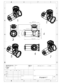
Job description of this system: (Depending on the shapes in the map file)
In the inventive system whose overview is shown in figure (assem1). On the one hand, the filtrate air enters the filter and passes through the turbo-fan and the hex-shaped (part6), which is cooled by the thermoelectric generator, and enters the T-shaped compartment (part5) by two magnetic (magnetic field generator) shapes (part2, part5) is encircled. Since magnetic material is divided into three categories in the field of physics, magnetic material (magnetic particle, magnetism, and magnetic), oxygen is a paramagnetic matter group. It is magnetized in the presence of a magnetic field, and in the direction of the magnetic field toward Engine driven. But nitrogen escapes from the magnetic field due to its magnetism, and it is removed from the T-chamber, and as this process is controlled by an electronic board (temperature of the intake air, the air temperature of the exhaust air, the concentration of oxygen and air nitrogen and the intensity of the magnetic field) to the engine performance to the best Shape possible.
(i). Due to the lack of use of kinetic energy, the engine has a low energy loss compared to previous technology.
(ii). This system reduces air pollution because it prevents the addition of nitrogen to the engine and reduces the formation of nitrogen gas derivatives at the outlet of the engine that causes burns.
(iii). Accurate operation of the system due to its digital control.
(iv). Like previous technology, no lubrication is required.
(v). Problem of delay (turbulence) in the new innovative system.
(vi). Using this device, you will no longer need to use (Diesel Exhaust Fluid DEEF) supplement to reduce contamination.
(vii). The space used in this device is very low compared to previous technology.
(viii) Cost less than previous technology.
(ix) Less maintenance costs than previous technology.
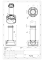
All sizes written in the plan are in millimeters.
Fig.1-2
Fig.1-2
Fig.3
Fig.4
Fig.5
Fig.6
Fig.7
Fig.8
Fig.9
This invention is usable in a variety of internal combustion engines (such as diesel and gasoline). As soon as the vehicle is started up, the electronic board, which controls the function of the system, coordinates the system's performance with the engine's requirements.
In the new system, the filtered air is filtered through the filter and passes through the turboprop and the heat sink cooled by the thermoelectric generator and enters the T-shaped chamber, surrounded by two magnetic (magnetic field generator). Since magnetic material is divided into three categories in the field of physics, magnetic material ( Paramagnetism , Diamagnetism , Ferromagnet ) oxygen is a paramagnetic matter group. It is magnetized in the presence of a magnetic field, and in the direction of the magnetic field toward Engine driven. But nitrogen escapes from the magnetic field due to its magnetism, leaving the T-shaped compartment out. Because all parameters are controlled by the electronic board, the performance of the engine is as good as possible.
Also, at any moment when the amount of oxygen or the pressure of the air entering the machine is low. Electronic board Enables the turbo fan to resolve this issue. This happens often at heights.
Examples
As previously stated, this invention is applicable to all industries that are in some way related to the separation of oxygen and nitrogen.
Claims (13)
- Design and manufacture of a system for increasing efficiency and reducing engine pollution by using a magnetic field and thermoelectric cooling with a turbo fan to increase power, reduce fuel consumption and reduce emissions gas generated by motors by electronic control. Which is installed between the air filter and the intake valve of the engine air.
- According to Claim No. 1, the electronic board used in the system is to coordinate the operation of the engine and the machine.
- According to Claim No. 1, the magnetic field is used to separate the air components (oxygen and nitrogen) from each other.
- According to Claim No. 1, the thermoelectric cooling was used to reduce the input temperature to the motor.
- According to Claim No. 1, the components of the machine are as follows: 1-main body 2-motors brushles 3-heatsink and thermo-electric 4-cone 5-chamber T 6- Electromagnetic Magnet 7- Permanent magnet 8. Electronic board 9. Turbofan blade
- According to Claim No. 5: All components are placed inside the main body. The main object is to protect other components.
- According to Claim No. 5: The brushless motor has a duty to suck air into the system and then send oxygen to the engine. And controlled by electronic wiring.
- According to claim No. 5: Heat sink and thermoelectric cooling are responsible for the cooling of the inlet air. And controlled by electronic board.
- According to Claim No. 5, the cone has the task of directing the air inlet to the cooling chamber T.
- According to Claim No. 5, the T-chamber places the magnetic and electromagnetic fields on the air and separates oxygen and nitrogen from each other, and then sends air saturated from oxygen to the engine.
- According to claim No. 5: An electromagnetic magnet is a variable power magnet that is mounted on the body of the T enclosure and controlled by an electronic board.
- According to Claim No. 5: A permanent magnet consisting of a neodymium-shaped disk magnet that generates magnetic field with an electromagnet magnet.
- According to Claim No. 5: An electronic board consisting of a microcontroller and a sensor (input air temperature, output air temperature, air oxygen concentration, air pressure (inlet and outlet), and magnetic sensor) and is responsible for accurate control of the system.
Applications Claiming Priority (2)
| Application Number | Priority Date | Filing Date | Title |
|---|---|---|---|
| IR139750140003005882 | 2018-10-11 | ||
| IR13973005890 | 2018-10-11 |
Publications (1)
| Publication Number | Publication Date |
|---|---|
| WO2020089948A1 true WO2020089948A1 (en) | 2020-05-07 |
Family
ID=70464763
Family Applications (1)
| Application Number | Title | Priority Date | Filing Date |
|---|---|---|---|
| PCT/IR2019/050002 Ceased WO2020089948A1 (en) | 2018-10-11 | 2019-01-23 | Reducing pollution of an engine by separating gases using a magnetic field |
Country Status (1)
| Country | Link |
|---|---|
| WO (1) | WO2020089948A1 (en) |
Cited By (1)
| Publication number | Priority date | Publication date | Assignee | Title |
|---|---|---|---|---|
| CN114788974A (en) * | 2022-04-07 | 2022-07-26 | 坤育环境发展(云南)有限公司 | Low-oxygen sulfur-free drying method and device |
Citations (1)
| Publication number | Priority date | Publication date | Assignee | Title |
|---|---|---|---|---|
| US20090178556A1 (en) * | 2007-12-25 | 2009-07-16 | Sakutaro Hoshi | Method for separating gas components and separator for the same |
-
2019
- 2019-01-23 WO PCT/IR2019/050002 patent/WO2020089948A1/en not_active Ceased
Patent Citations (1)
| Publication number | Priority date | Publication date | Assignee | Title |
|---|---|---|---|---|
| US20090178556A1 (en) * | 2007-12-25 | 2009-07-16 | Sakutaro Hoshi | Method for separating gas components and separator for the same |
Cited By (2)
| Publication number | Priority date | Publication date | Assignee | Title |
|---|---|---|---|---|
| CN114788974A (en) * | 2022-04-07 | 2022-07-26 | 坤育环境发展(云南)有限公司 | Low-oxygen sulfur-free drying method and device |
| CN114788974B (en) * | 2022-04-07 | 2024-03-22 | 坤育环境发展(云南)有限公司 | Method and device for low-oxygen sulfur-free drying |
Similar Documents
| Publication | Publication Date | Title |
|---|---|---|
| US20060260308A1 (en) | Toroidal intersecting vane gas management system | |
| US8943823B2 (en) | Fluid handling system having dedicated EGR turbo-generator | |
| Ricardo et al. | Overview of boosting options for future downsized engines | |
| US20110173974A1 (en) | Variable flow wastegate | |
| EP0401284A4 (en) | Internal combustion engine turbosystem and method | |
| Zhao et al. | Parametric study of a turbocompound diesel engine based on an analytical model | |
| EP1957766A2 (en) | Turbocharged engine system and method of operation | |
| US10197020B2 (en) | Electrically driven compressor-expander for a turbocharged engine system and associated flow control valves | |
| WO2009092670A1 (en) | Air-inlet system for internal combustion engine, air-conditioning system and combustion engine comprising the air-inlet system | |
| Zhu et al. | Potential for energy and emissions of asymmetric twin-scroll turbocharged diesel engines combining inverse Brayton cycle system | |
| Liu et al. | Experimental study on thermal balance of regulated two-stage turbocharged diesel engine at variable altitudes | |
| EP2690268A2 (en) | Flywheel assembly for a turbocharger | |
| WO2020089948A1 (en) | Reducing pollution of an engine by separating gases using a magnetic field | |
| JPS58187521A (en) | Exhaust gas turbocharger | |
| US20130047604A1 (en) | Internal combustion engine and method for operating internal combustion engine | |
| Ryder et al. | The impact of future engine and vehicle drivetrains on turbocharging system architecture | |
| Lee et al. | Supercharging performance of a gasoline engine with a supercharger | |
| Knecht et al. | Supercharging | |
| Leahu et al. | Researches on the influence of pressure wave compressor on the intake air temperature at the supercharged engines | |
| GB2533661A (en) | 2 - stage compression and expansion wankel engines, with interstage intercooling, using exhaust powered wankel rotary superchargers, | |
| CN115030811A (en) | Double-boosting high-prime power system of unmanned helicopter | |
| Soundararaju et al. | Turbocharger Lag Mitigation System | |
| Hong | Development of turbocharger for improving diesel engine matching performance | |
| CN105358802A (en) | engine turbo system | |
| CN111852697A (en) | Mechanically supercharged internal combustion engine and method of operating same |
Legal Events
| Date | Code | Title | Description |
|---|---|---|---|
| 121 | Ep: the epo has been informed by wipo that ep was designated in this application |
Ref document number: 19879247 Country of ref document: EP Kind code of ref document: A1 |
|
| NENP | Non-entry into the national phase |
Ref country code: DE |
|
| 122 | Ep: pct application non-entry in european phase |
Ref document number: 19879247 Country of ref document: EP Kind code of ref document: A1 |