WO2020062444A1 - Network device, user equipment, wireless communication method and storage medium - Google Patents
Network device, user equipment, wireless communication method and storage medium Download PDFInfo
- Publication number
- WO2020062444A1 WO2020062444A1 PCT/CN2018/113905 CN2018113905W WO2020062444A1 WO 2020062444 A1 WO2020062444 A1 WO 2020062444A1 CN 2018113905 W CN2018113905 W CN 2018113905W WO 2020062444 A1 WO2020062444 A1 WO 2020062444A1
- Authority
- WO
- WIPO (PCT)
- Prior art keywords
- uplink
- user equipment
- wireless communication
- srs resource
- transmission beam
- Prior art date
- Legal status (The legal status is an assumption and is not a legal conclusion. Google has not performed a legal analysis and makes no representation as to the accuracy of the status listed.)
- Ceased
Links
Images


Classifications
-
- H—ELECTRICITY
- H04—ELECTRIC COMMUNICATION TECHNIQUE
- H04L—TRANSMISSION OF DIGITAL INFORMATION, e.g. TELEGRAPHIC COMMUNICATION
- H04L5/00—Arrangements affording multiple use of the transmission path
- H04L5/0001—Arrangements for dividing the transmission path
- H04L5/0014—Three-dimensional division
- H04L5/0023—Time-frequency-space
- H04L5/0025—Spatial division following the spatial signature of the channel
-
- H—ELECTRICITY
- H04—ELECTRIC COMMUNICATION TECHNIQUE
- H04B—TRANSMISSION
- H04B7/00—Radio transmission systems, i.e. using radiation field
- H04B7/02—Diversity systems; Multi-antenna system, i.e. transmission or reception using multiple antennas
- H04B7/04—Diversity systems; Multi-antenna system, i.e. transmission or reception using multiple antennas using two or more spaced independent antennas
- H04B7/0404—Diversity systems; Multi-antenna system, i.e. transmission or reception using multiple antennas using two or more spaced independent antennas the mobile station comprising multiple antennas, e.g. to provide uplink diversity
-
- H—ELECTRICITY
- H04—ELECTRIC COMMUNICATION TECHNIQUE
- H04B—TRANSMISSION
- H04B7/00—Radio transmission systems, i.e. using radiation field
- H04B7/02—Diversity systems; Multi-antenna system, i.e. transmission or reception using multiple antennas
- H04B7/04—Diversity systems; Multi-antenna system, i.e. transmission or reception using multiple antennas using two or more spaced independent antennas
- H04B7/06—Diversity systems; Multi-antenna system, i.e. transmission or reception using multiple antennas using two or more spaced independent antennas at the transmitting station
- H04B7/0686—Hybrid systems, i.e. switching and simultaneous transmission
- H04B7/0691—Hybrid systems, i.e. switching and simultaneous transmission using subgroups of transmit antennas
-
- H—ELECTRICITY
- H04—ELECTRIC COMMUNICATION TECHNIQUE
- H04B—TRANSMISSION
- H04B7/00—Radio transmission systems, i.e. using radiation field
- H04B7/02—Diversity systems; Multi-antenna system, i.e. transmission or reception using multiple antennas
- H04B7/04—Diversity systems; Multi-antenna system, i.e. transmission or reception using multiple antennas using two or more spaced independent antennas
- H04B7/06—Diversity systems; Multi-antenna system, i.e. transmission or reception using multiple antennas using two or more spaced independent antennas at the transmitting station
- H04B7/0686—Hybrid systems, i.e. switching and simultaneous transmission
- H04B7/0695—Hybrid systems, i.e. switching and simultaneous transmission using beam selection
- H04B7/06952—Selecting one or more beams from a plurality of beams, e.g. beam training, management or sweeping
- H04B7/06966—Selecting one or more beams from a plurality of beams, e.g. beam training, management or sweeping using beam correspondence; using channel reciprocity, e.g. downlink beam training based on uplink sounding reference signal [SRS]
-
- H—ELECTRICITY
- H04—ELECTRIC COMMUNICATION TECHNIQUE
- H04B—TRANSMISSION
- H04B7/00—Radio transmission systems, i.e. using radiation field
- H04B7/02—Diversity systems; Multi-antenna system, i.e. transmission or reception using multiple antennas
- H04B7/04—Diversity systems; Multi-antenna system, i.e. transmission or reception using multiple antennas using two or more spaced independent antennas
- H04B7/08—Diversity systems; Multi-antenna system, i.e. transmission or reception using multiple antennas using two or more spaced independent antennas at the receiving station
- H04B7/0868—Hybrid systems, i.e. switching and combining
- H04B7/088—Hybrid systems, i.e. switching and combining using beam selection
-
- H—ELECTRICITY
- H04—ELECTRIC COMMUNICATION TECHNIQUE
- H04L—TRANSMISSION OF DIGITAL INFORMATION, e.g. TELEGRAPHIC COMMUNICATION
- H04L25/00—Baseband systems
- H04L25/02—Details ; arrangements for supplying electrical power along data transmission lines
- H04L25/0202—Channel estimation
- H04L25/0224—Channel estimation using sounding signals
- H04L25/0226—Channel estimation using sounding signals sounding signals per se
-
- H—ELECTRICITY
- H04—ELECTRIC COMMUNICATION TECHNIQUE
- H04L—TRANSMISSION OF DIGITAL INFORMATION, e.g. TELEGRAPHIC COMMUNICATION
- H04L5/00—Arrangements affording multiple use of the transmission path
- H04L5/003—Arrangements for allocating sub-channels of the transmission path
- H04L5/0048—Allocation of pilot signals, i.e. of signals known to the receiver
-
- H—ELECTRICITY
- H04—ELECTRIC COMMUNICATION TECHNIQUE
- H04L—TRANSMISSION OF DIGITAL INFORMATION, e.g. TELEGRAPHIC COMMUNICATION
- H04L5/00—Arrangements affording multiple use of the transmission path
- H04L5/0091—Signalling for the administration of the divided path, e.g. signalling of configuration information
- H04L5/0094—Indication of how sub-channels of the path are allocated
-
- H—ELECTRICITY
- H04—ELECTRIC COMMUNICATION TECHNIQUE
- H04W—WIRELESS COMMUNICATION NETWORKS
- H04W72/00—Local resource management
- H04W72/04—Wireless resource allocation
- H04W72/044—Wireless resource allocation based on the type of the allocated resource
- H04W72/046—Wireless resource allocation based on the type of the allocated resource the resource being in the space domain, e.g. beams
-
- H—ELECTRICITY
- H04—ELECTRIC COMMUNICATION TECHNIQUE
- H04W—WIRELESS COMMUNICATION NETWORKS
- H04W72/00—Local resource management
- H04W72/20—Control channels or signalling for resource management
- H04W72/23—Control channels or signalling for resource management in the downlink direction of a wireless link, i.e. towards a terminal
-
- H—ELECTRICITY
- H04—ELECTRIC COMMUNICATION TECHNIQUE
- H04L—TRANSMISSION OF DIGITAL INFORMATION, e.g. TELEGRAPHIC COMMUNICATION
- H04L5/00—Arrangements affording multiple use of the transmission path
- H04L5/003—Arrangements for allocating sub-channels of the transmission path
- H04L5/0048—Allocation of pilot signals, i.e. of signals known to the receiver
- H04L5/0051—Allocation of pilot signals, i.e. of signals known to the receiver of dedicated pilots, i.e. pilots destined for a single user or terminal
Definitions
- Embodiments of the present disclosure generally relate to the field of wireless communications, and in particular, to a network-side device, a user equipment, a wireless communication method, and a computer-readable storage medium. More specifically, the present disclosure relates to a network-side device in a wireless communication system, a user equipment in the wireless communication system, a wireless communication method performed by the network-side device in the wireless communication system, and a wireless communication A wireless communication method performed by user equipment in the system and a computer-readable storage medium.
- Beamforming is a signal preprocessing technology based on an antenna array. Beamforming can produce a directional beam by adjusting the weighting coefficients of each array element in the antenna array, thereby obtaining a significant array gain. Therefore, beamforming technology has great advantages in terms of expanding coverage, improving edge throughput, and interference suppression.
- the network side device can select a suitable uplink transmission beam for the user equipment and notify the user equipment of the selected uplink transmission beam, so that the user equipment can use the uplink transmission beam selected by the network side device. To send uplink signals.
- each antenna board can independently strike multiple beam directions. That is, each antenna board can only play one beam direction on one OFDM (Orthogonal Frequency Division Multiplexing) symbol or one time slot, and different antennas on one OFDM symbol or one time slot The boards can independently hit their respective beam directions.
- OFDM Orthogonal Frequency Division Multiplexing
- the existing communication standard cannot be applied to a configuration in which the user equipment is equipped with multiple antenna boards. That is, when the user equipment is equipped with multiple antenna boards, how the network-side device notifies the user equipment of the selected uplink transmission beam is one of the technical problems to be solved urgently.
- the network-side device can notify the user equipment of the selected uplink transmission beam if the user equipment is equipped with multiple antenna boards, thereby optimizing the determination process of the uplink transmission beam.
- An object of the present disclosure is to provide a network-side device, user equipment, wireless communication method, and storage medium, so that the network-side device can notify the user equipment of the selected uplink transmission beam if the user equipment is equipped with multiple antenna boards, Thereby, the determination process of the uplink transmission beam is optimized.
- a network-side device including a processing circuit configured to configure the user equipment from a plurality of transmit beams on multiple antenna boards of the user equipment for sending an uplink signal. Transmitting a beam; and generating configuration information that indicates a transmitting beam for transmitting an uplink signal.
- a user equipment including a processing circuit configured to: receive configuration information indicating a transmission beam used to transmit an uplink signal; and from a plurality of the user equipment according to the configuration information.
- a transmission beam for transmitting an uplink signal is determined from a plurality of transmission beams on the antenna boards.
- a wireless communication method performed by a network-side device, including: configuring the user equipment from multiple transmit beams on multiple antenna boards of a user equipment to send an uplink signal. A transmission beam; and generating configuration information that indicates a transmission beam used to send an uplink signal.
- a wireless communication method performed by a user equipment, including: receiving configuration information indicating a transmission beam used to transmit an uplink signal; and from a plurality of the user equipment according to the configuration information.
- a transmission beam for transmitting an uplink signal is determined from a plurality of transmission beams on the antenna boards.
- a computer-readable storage medium including executable computer instructions that, when executed by a computer, cause the computer to perform the wireless communication method according to the present disclosure.
- Using the network-side device, user equipment, wireless communication method, and computer-readable storage medium according to the present disclosure enables the network-side device to configure the user equipment from multiple transmission beams on multiple antenna boards of the user equipment for sending uplink The transmission beam of the signal, and can generate configuration information indicating the configured transmission beam. In this way, the network-side device can notify the user equipment of the selected uplink transmission beam when the user equipment is equipped with multiple antenna boards, thereby optimizing the determination process of the uplink transmission beam.
- FIG. 1 is a schematic diagram illustrating a process of selecting a transmission beam for transmitting an uplink data signal in the prior art
- FIG. 2 is a block diagram showing an example of a configuration of a network-side device according to an embodiment of the present disclosure
- FIG. 3 is a schematic diagram showing a mapping relationship between a transmission beam and an SRS (Sounding Reference Signal) resource according to an embodiment of the present disclosure
- FIG. 4 (a) is a schematic diagram illustrating configuration information of a transmission beam indicating transmission of an uplink data signal according to an embodiment of the present disclosure
- FIG. 4 (b) is a schematic diagram illustrating configuration information of a transmission beam indicating transmission of an uplink data signal according to an embodiment of the present disclosure
- FIG. 5 is a schematic diagram showing contents of a SpatialRelationInfo parameter according to an embodiment of the present disclosure
- FIG. 6 (a) is a schematic diagram illustrating configuration information of a transmission beam indicating transmission of an uplink data signal according to an embodiment of the present disclosure
- FIG. 6 (b) is a schematic diagram showing configuration information of a transmission beam indicating transmission of an uplink data signal according to an embodiment of the present disclosure
- FIG. 6 (c) is a schematic diagram illustrating configuration information of a transmission beam indicating transmission of an uplink data signal according to an embodiment of the present disclosure
- 6 (d) is a schematic diagram illustrating configuration information of a transmission beam indicating transmission of an uplink data signal according to an embodiment of the present disclosure
- 6 (e) is a schematic diagram illustrating configuration information of a transmission beam indicating transmission of an uplink data signal according to an embodiment of the present disclosure
- FIG. 7 is a schematic diagram illustrating a process of selecting a transmission beam for transmitting an uplink data signal according to an embodiment of the present disclosure
- FIG. 8 is a signaling flowchart illustrating selection of a transmission beam for transmitting an uplink data signal according to an embodiment of the present disclosure
- FIG. 9 is a block diagram showing an example of a configuration of a user equipment according to an embodiment of the present disclosure.
- FIG. 10 is a flowchart illustrating a wireless communication method performed by a network-side device according to an embodiment of the present disclosure
- FIG. 11 is a flowchart illustrating a wireless communication method performed by a user equipment according to an embodiment of the present disclosure
- FIG. 12 is a block diagram showing a first example of a schematic configuration of a gNB (base station device in a 5G communication system);
- FIG. 13 is a block diagram showing a second example of a schematic configuration of a gNB
- FIG. 14 is a block diagram showing an example of a schematic configuration of a smartphone.
- FIG. 15 is a block diagram showing an example of a schematic configuration of a car navigation device.
- Example embodiments are provided so that this disclosure will be thorough, and will fully convey its scope to those skilled in the art. Numerous specific details are set forth, such as examples of specific components, devices, and methods, to provide a thorough understanding of embodiments of the present disclosure. It will be apparent to those skilled in the art that specific details need not be used, that example embodiments may be implemented in many different forms, and they should not be construed as limiting the scope of the disclosure. In some example embodiments, well-known processes, well-known structures, and well-known technologies are not described in detail.
- multiple antenna boards of a UE correspond to one or more SRS resource sets, and each of multiple transmit beams of the UE corresponds to one SRS resource.
- the base station may configure multiple SRS resource sets for the UE, and different SRS resource sets may have different purposes. That is, the beams on different antenna boards of the UE may have different purposes, while the beams located on the same antenna board have the same purpose.
- four purposes are defined, which are beam management, channel-state information (CSI) acquisition based on codebook (CSI) transmission, and non-codebook-based transmission. CSI acquisition and antenna switching.
- CSI channel-state information
- CSI codebook
- One of four purposes can be configured for each SRS resource set.
- the relevant code in the standard is as follows:
- Usage indicates the purpose of the SRS resource set and is selected from any one of beam management, CSI acquisition based on codebook transmission, CSI acquisition based on non-codebook transmission, and antenna switching.
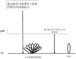
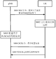
- FIG. 1 is a schematic diagram illustrating a process of selecting a transmission beam for transmitting an uplink data signal in the prior art.
- the uplink beam selection process is defined to include three steps of SRS-based beam scanning, RRC (Radio Resource Control) configuration, and SRS resource indication.
- the gNB configures an SRS resource set for beam management to the UE through RRC signaling.
- the UE may perform an uplink beam scanning process based on the configuration of the gNB.
- the gNB can measure the quality of the acquired beams, such as measuring RSRP (Reference Signaling and Receiving Power) to select the best uplink transmitting beam.
- the base station can configure the SRS resource set based on codebook transmission or non-codebook based CSI acquisition for the UE through RRC signaling, and configure a transmission beam for each SRS resource in each resource set.
- the UE may perform SRS beam transmission based on the reconfiguration of the gNB to assist the base station to obtain uplink CSI.
- the UE may perform the SRS resource obtained by the CSI based on codebook transmission or the SRS resource obtained by the CSI based on non-codebook transmission.
- the SRS beam is transmitted to assist the base station in obtaining the CSI.
- the gNB needs to further activate one SRS beam among the multiple semi-static SRS beams through a MAC CE (Media Access Control Element).
- MAC CE Media Access Control Control Element
- the gNB After performing the necessary measurements, the gNB notifies the UE of the selected transmission beam for sending uplink signals through SRI (SRS Resource Indicator) in DCI (Downlink Control Information) signaling.
- SRI SRS Resource Indicator
- DCI Downlink Control Information
- the gNB may indicate to the UE an SRS resource set obtained by using CSI based on codebook transmission in the most recent time slot or one SRS resource in the set of SRS resources obtained by using CSI based on non-codebook transmission.
- the UE can use the beam corresponding to the SRS resource indicated by the gNB to perform uplink data transmission, that is, send a PUSCH (Physical Uplink Shared Channel) signal.
- PUSCH Physical Uplink Shared Channel
- the gNB needs to configure the SRS resource set for the UE twice through RRC signaling, the first time is to configure the SRS resource set for beam management, and the second is to configure The set of SRS resources used for CSI acquisition, which undoubtedly increases the signaling overhead.
- the two configurations will inevitably lead to inaccurate configuration and may cause unnecessary RRC reconfiguration.
- gNB needs to further activate one SRS beam among multiple semi-static SRS beams through MAC CE, which further increases the signaling overhead and the complexity of the process.
- DCI indicates an SRS resource set in the SRS resource set acquired based on CSI transmitted through codebook or an SRS resource set acquired based on CSI transmitted in non-codebook, without considering the antenna plate of the UE. information.
- the gNB does not consider the antenna board information of the UE when it configures the UE with a transmit beam for sending uplink non-data signals.
- the present disclosure proposes a network-side device, a user equipment in a wireless communication system, a wireless communication method performed by a network-side device in a wireless communication system, and a wireless communication method performed by a user equipment in a wireless communication system. And a computer-readable storage medium, so that the network-side device can notify the user equipment of the selected uplink transmission beam if the user equipment is equipped with multiple antenna boards, simplify the determination process of the uplink transmission beam, and reduce signaling overhead and system Delay.
- the network-side device may be any type of TRP (Transmit and Receive Port).
- the TRP may have sending and receiving functions.
- the TRP may receive information from user equipment and base station equipment, and may also send information to user equipment and base station equipment.
- the TRP may serve user equipment and is controlled by the base station equipment. That is, the base station device provides services to the user equipment through TRP.
- the network-side device described in the present disclosure may also be a base station device, such as an eNB (evolved node B), or a gNB.
- the user equipment may be a mobile terminal such as a smartphone, a tablet personal computer (PC), a notebook PC, a portable game terminal, a portable / dongle-type mobile router, and a digital camera device, or a vehicle-mounted terminal such as a car navigation device ).
- the user equipment may also be implemented as a terminal (also called a machine type communication (MTC) terminal) that performs machine-to-machine (M2M) communication.
- MTC machine type communication
- M2M machine-to-machine
- the user equipment may be a wireless communication module (such as an integrated circuit module including a single chip) mounted on each of the terminals described above.
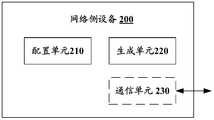
- FIG. 2 is a block diagram illustrating an example of a configuration of a network-side device 200 according to an embodiment of the present disclosure.
- the network-side device 200 may include a configuration unit 210 and a generation unit 220.
- each unit of the network-side device 200 may be included in a processing circuit.
- the network-side device 200 may include one processing circuit or multiple processing circuits.
- the processing circuit may include various discrete functional units to perform various different functions and / or operations. It should be noted that these functional units may be physical entities or logical entities, and units with different names may be implemented by the same physical entity.
- the configuration unit 210 may configure the user equipment from a plurality of transmit beams on multiple antenna boards of the user equipment to transmit a transmission beam for transmitting an uplink signal.
- the user equipment may be located within the service range of the network-side device.
- the user equipment may be geographically located within the coverage of the network-side device 200, or the user equipment is close to the network-side device 200.
- the generating unit 220 may generate configuration information indicating a transmission beam for transmitting an uplink signal. That is, the configuration information may indicate a transmission beam for transmitting an uplink signal among multiple transmission beams on multiple antenna boards of the user equipment.
- a user equipment can be configured with a transmission beam for transmitting an uplink signal from multiple transmission beams on multiple antenna boards of the user equipment, and can generate an indication of the Configuration information of the configured transmit beam.
- the network-side device 200 can notify the user equipment of the selected uplink transmission beam if the user equipment is equipped with multiple antenna boards, thereby optimizing the determination process of the uplink transmission beam.
- the user equipment is equipped with multiple antenna boards, and the multiple antenna boards correspond to the multiple SRS resource sets one-to-one. That is, the number of antenna boards provided by the user equipment is consistent with the number of SRS resource sets, and there is a one-to-one correspondence between the antenna boards and the SRS resource sets. Further, each antenna board of the user equipment includes one or more beam directions, that is, for each antenna board, there is a one-to-one correspondence between the beam and the SRS resource.
- FIG. 3 is a schematic diagram illustrating a mapping relationship between a transmission beam and an SRS resource according to an embodiment of the present disclosure.
- the user equipment may be provided with four antenna boards, and the four antenna boards are arranged in different directions of the user equipment. Therefore, the user equipment may have four SRS resource sets, which are SRS resource set 0, SRS resource set 1, SRS resource set 2, and SRS resource set 3. Further, the relationship between the SRS resource and the transmission beam is described using the SRS resource set 0 as an example.
- the SRS resource set 0 includes N SRS resources, which are SRS resource 0, SRS resource 1, ..., and SRS resource N-1, and the N SRS resources correspond to the N transmission beams one-to-one.
- the SRS resource set corresponds to the antenna board one-to-one
- the SRS resource in the SRS resource set corresponds to the beam on the antenna board corresponding to the SRS resource set.
- FIG. 3 only shows a case where the user equipment includes four antenna boards, and the user equipment may of course also have other numbers of antenna boards.
- FIG. 3 only shows the case of the SRS resources included in the SRS resource set 0, and it is the same for other SRS resource sets, and each SRS resource set may include one or more SRS resources.
- the configuration information generated by the generating unit 220 may indicate a transmission beam for transmitting an uplink signal among multiple transmission beams on multiple antenna boards of the user equipment. That is, the configuration information can indicate which beam on which antenna plate the transmit beam used to send the uplink signal is located.
- a transmission beam for transmitting an uplink signal may include one or more transmission beams. That is, the configuration unit 210 may configure one or more transmit beams for the user equipment to send an uplink signal. Further, the configuration information generated by the generating unit 220 may indicate one or more transmission beams for transmitting an uplink signal.
- the network-side device 200 may further include a communication unit 230 for sending configuration information to the user equipment.
- the uplink signal to be sent by the user equipment may include a data signal.
- the data signal here may include a PUSCH signal.
- the communication unit 230 may send the generated configuration information to the user equipment through low-level signaling.
- low-level signaling may be implemented as DCI signaling at the physical layer, such as DCI format 0.
- the uplink signal to be sent by the user equipment may include a non-data signal.
- the non-data signal may include an uplink reference signal and an uplink control signal.
- the uplink control signal may be a PUCCH (Physical Uplink Control Channel) signal
- the uplink reference signal may include an SRS.
- the communication unit 230 may send the generated configuration information to the user equipment through high-level signaling.
- high-level signaling may include, but is not limited to, RRC signaling.
- PUSCH signals For uplink data signals (PUSCH signals)
- the configuration information generated by the generating unit 220 may include SRS resource set indication information and SRS resource indication information.
- the SRS resource set indication information may indicate an SRS resource set where a transmission beam used to send an uplink signal is located.
- the SRS resource set indication information may include identification information of an SRS resource set where a transmission beam used to send an uplink signal is located.
- the SRS resource set may be numbered, and then the SRSI (SRS Resource Set Indicator) is used to indicate the number of the SRS resource set used to send the uplink signal.
- SRSI SRS Resource Set Indicator
- the SRS resource indication information may indicate a resource occupied by a transmission beam for transmitting an uplink signal in the SRS resource set.
- the SRS resource indication information may include identification information of resources occupied by a transmission beam used to send an uplink signal within an SRS resource set in which the resource is located.
- SRI SRS Resource Indicator, SRS resource indicator
- each SRS resource set includes 8 SRS resources, which are numbered 0, 1, 2, 3, and 4, respectively.
- the device sends the transmit beam of the uplink signal.
- the configuration information may include multiple sets of indication information, and each set of indication information includes one SRS resource set indication information and one SRS resource indication information. In this way, multiple transmit beams can be used to send uplink signals.
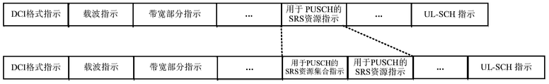
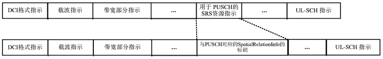
- FIG. 4 (a) is a schematic diagram illustrating configuration information of a transmission beam indicating transmission of an uplink data signal according to an embodiment of the present disclosure.
- the upper half of FIG. 4 (a) shows the indication of the uplink transmission beam in the DCI format 0_1 in the prior art, and the lower half shows the modified DCI format according to the embodiment of the present disclosure.
- the DCI format 0_1 includes an indication of the SRS resource for the PUSCH signal. This indication corresponds to, for example, the DCI indication in FIG. One SRS resource in the SRS resource set acquired by CSI and the SRS resource set used for non-codebook-based CSI acquisition.
- the DCI format may include an indication of the SRS resource set for the PUSCH signal (such as the SRSI described above) and an SRS resource indication for the PUSCH signal (as in the previous text) SRI) both.
- FIG. 4 (b) is a schematic diagram illustrating configuration information of a transmission beam indicating transmission of an uplink data signal according to an embodiment of the present disclosure.
- FIG. 4 (a) in FIG. 4 (b), two sets of indication information are included, and each set of indication information includes an SRS resource set indication for a PUSCH signal and an SRS resource indication for a PUSCH signal.
- each set of indication information includes an SRS resource set indication for a PUSCH signal and an SRS resource indication for a PUSCH signal.
- the structure of the DCI shown in FIG. 4 (b) can also be extended to more than three sets of indication information.
- a transmission beam for transmitting an uplink data signal can be indicated by a combination of SRSI and SRI, so that the information of the antenna board where the transmission beam is located can be simply and clearly indicated.
- the configuration information generated by the generating unit 220 may include an RRC parameter to instruct the user equipment to send an uplink data signal using a transmission beam corresponding to the RRC parameter. That is, the RRC parameter has a corresponding relationship with the transmission beam. For a certain RRC parameter, a unique transmit beam can be determined. Therefore, the network-side device 200 may notify the user equipment of the information about the transmission beam through such RRC parameters.
- a transmission beam corresponding to an RRC parameter represents a transmission beam used by an uplink signal corresponding to the RRC parameter. That is, the RRC parameter has a corresponding relationship with the uplink signal.
- a unique uplink signal can be determined. Specifically, when an RRC parameter is an RRC parameter for an uplink signal, it may be determined that the RRC parameter has a corresponding relationship with the uplink signal.
- the uplink signal corresponding to the RRC parameter includes at least one of the following: an uplink data signal corresponding to the RRC parameter, an uplink control signal corresponding to the RRC parameter, and an uplink reference signal corresponding to the RRC parameter.
- the uplink data signal may be, for example, a PUSCH signal
- the uplink control signal may be, for example, a PUCCH signal
- the uplink reference signal may be, for example, an SRS.
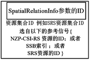
- FIG. 5 is a schematic diagram showing contents of a SpatialRelationInfo parameter according to an embodiment of the present disclosure.
- the SpatialRelationInfo parameter here represents an RRC parameter for controlling a specific uplink signal (hereinafter referred to as uplink signal A).
- the SpatialRelationInfo parameter includes an ID, that is, identification information.
- the SpatialRelationInfo parameter also includes information for sending an uplink signal corresponding to the SpatialRelationInfo parameter, that is, a transmission beam of the uplink signal A.
- the transmit beam used to send the uplink signal A may be the same as the transmit or receive beam of one of the following reference signals: NZP-CSI-RS (Non Zero Power-Channel State Information-Reference Signal) on a specified resource.
- NZP-CSI-RS Non Zero Power-Channel State Information-Reference Signal
- the SpatialRelationInfo parameter may further include a resource set ID, for example, an SRS resource set ID, used to indicate an SRS resource set (that is, an antenna panel) where a transmission beam used to send the uplink signal A is located.
- the uplink signal A may be an uplink signal that has been transmitted, and the uplink signal A may include any one of a PUSCH signal, a PUCCH signal, and an SRS. That is, the SpatialRelationInfo parameter shown in FIG. 5 may be a SpatialRelationInfo parameter corresponding to a PUSCH signal, a SpatialRelationInfo parameter corresponding to a PUCCH signal, or a SpatialRelationInfo parameter corresponding to an SRS.
- all SpatialRelationInfo parameters corresponding to the uplink signals that have been transmitted can be numbered so that each SpatialRelationInfo parameter has unique ID information.
- the configuration information generated by the generating unit 220 includes a SpatialRelationInfo parameter corresponding to the uplink signal A, it means that the transmission beam used to send the uplink signal (referred to as the uplink signal B) is the same as the transmission beam of the uplink signal A.
- the uplink signal B indicates an uplink signal to be transmitted.
- the transmitted beam of the uplink signal A and the transmission beam of the uplink signal B to be transmitted can be mapped by the numbered RRC parameters, so that the user equipment can know that Transmit beam of uplink signal B.
- the uplink signal B can only be a data signal
- the uplink signal A can be any uplink signal.
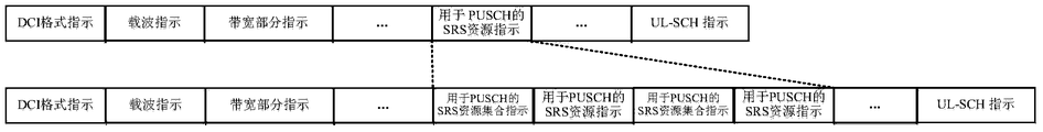
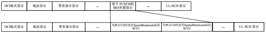
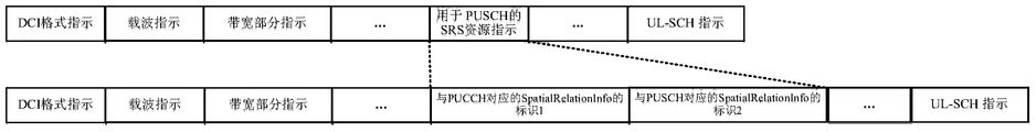
- 6 (a) to 6 (e) are schematic diagrams showing configuration information of a transmission beam indicating transmission of an uplink data signal according to an embodiment of the present disclosure.
- the upper half of FIG. 6 (a) shows the indication of the uplink transmission beam in the DCI format 0_1 in the prior art, and the lower half shows the modified DCI format according to the embodiment of the present disclosure.
- the DCI format 0_1 includes an indication of the SRS resource for the PUSCH signal. This indication corresponds to, for example, the DCI indication in FIG. One SRS resource in the SRS resource set acquired by CSI and the SRS resource set used for non-codebook-based CSI acquisition.
- the DCI format may include an identifier of the SpatialRelationInfo parameter corresponding to the PUCCH signal. That is, the transmission beam of the PUSCH signal to be transmitted by the user equipment may be the same as the transmission beam of the PUCCH signal corresponding to the SpatialRelationInfo parameter.
- FIG. 6 (b) shows an example of using the SpatialRelationInfo parameter corresponding to the PUSCH signal.
- the DCI format may include an identifier of the SpatialRelationInfo parameter corresponding to the PUSCH signal. That is, the transmission beam of the PUSCH signal to be transmitted by the user equipment may be the same as the transmission beam of the PUSCH signal corresponding to the SpatialRelationInfo parameter.
- FIG. 6 (c) shows an example of using SpatialRelationInfo parameters corresponding to SRS.
- the DCI format may include an identifier of the SpatialRelationInfo parameter corresponding to the SRS. That is, the transmission beam of the PUSCH signal to be transmitted by the user equipment may be the same as the transmission beam of the SRS corresponding to the SpatialRelationInfo parameter.
- the configuration unit 210 may configure one or more transmission beams for transmitting an uplink signal. That is, the configuration information may include one or more RRC parameters as described above to indicate multiple transmit beams, respectively.
- 6 (d) and 6 (e) are schematic diagrams showing configuration information corresponding to a plurality of transmission beams.
- the DCI format may include two identifiers of the SpatialRelationInfo parameter corresponding to the PUCCH signal. That is, there are two transmission beams of the PUSCH signal to be transmitted by the user equipment.
- the first transmission beam is the same as the transmission beam of the PUCCH signal corresponding to the SpatialRelationInfo parameter identified by the identifier 1.
- the second transmission beam is the same as the identifier 2.
- the transmitted beams of the PUCCH signals corresponding to the identified SpatialRelationInfo parameters are the same.
- the DCI format may include an identifier of a SpatialRelationInfo parameter corresponding to a PUCCH signal and an identifier of a SpatialRelationInfo parameter corresponding to a PUSCH signal. That is, there are two transmission beams of the PUSCH signal to be transmitted by the user equipment. The first transmission beam is the same as the transmission beam of the PUCCH signal corresponding to the SpatialRelationInfo parameter identified by the identifier 1. The second transmission beam is the same as the identifier 2. The transmitted beam of the PUSCH signal corresponding to the identified SpatialRelationInfo parameter is the same.
- the structure of the DCI shown in FIG. 6 (d) and FIG. 6 (e) may also include configuration information of more than three transmit beams.
- the uplink data signal to be sent can be associated with the uplink signal that has been sent through the SpatialRelationInfo parameter, so that the same transmit beam as the transmit beam of the uplink signal that has been sent can be used to send the uplink data that will be sent signal.
- the SpatialRelationInfo parameter information actually implicitly includes the information of the antenna plate.
- the network-side device 200 can notify the user equipment of information about the configured transmission beam.
- the configuration unit 210 may identify multiple transmit beams on multiple antenna boards of the user equipment according to a beam scanning process of the user equipment. That is, the configuration unit 210 may configure the user equipment with a transmission beam for transmitting an uplink data signal based on an uplink beam scanning process of the user equipment. In other words, the transmission beam configured for the user equipment to send an uplink data signal is used for beam management purposes.
- FIG. 7 is a schematic diagram illustrating a process of selecting a transmission beam for transmitting an uplink data signal according to an embodiment of the present disclosure.
- the gNB configures an SRS resource set for beam management to the UE through RRC signaling.
- the UE may perform an uplink beam scanning process based on the configuration of the gNB.
- the gNB may notify the UE of the selected transmission beam for sending an uplink signal through DCI signaling.
- the UE may use the beam corresponding to the SRS resource indicated by the gNB to perform uplink data transmission, that is, send a PUSCH signal.
- the gNB may generate the configuration information in the DCI signaling by any of the methods described above, and details are not described herein again.
- the gNB only needs to perform RRC configuration once to implement the selection of the uplink transmission beam, thereby saving signaling overhead, avoiding unnecessary RRC reconfiguration, and reducing system delay. Further, the MAC CE activation step is omitted in FIG. 7, further reducing the overhead.
- the transmission beam selected by the gNB for sending uplink signals is selected based on the uplink beam scanning process of the UE, so the configuration information carries the information of the antenna plate of the UE.
- the network-side device 200 can optimize a determination process of an uplink transmission beam.
- step S801 the gNB configures an SRS resource set for the UE for beam management through RRC signaling.
- step S802 the UE performs an uplink beam scanning process according to the configuration of the gNB.
- step S803 the gNB configures a transmission beam for transmitting a PUSCH signal.
- step S804 the gNB sends configuration information to the UE through DCI signaling to indicate a transmission beam for transmitting a PUSCH signal.
- step S805 the UE sends a PUSCH signal using a transmission beam designated by the gNB.
- the configuration information generated by the generating unit 220 may include SRS resource set indication information and SRS resource indication information.
- the SRS resource set indication information may indicate an SRS resource set where a transmission beam used to send an uplink signal is located.
- the SRS resource indication information may indicate resources occupied by a transmission beam used to send an uplink signal in the SRS resource set.
- the RRC parameter may be modified so that the network-side device 200 can notify the user equipment of a transmission beam for transmitting a PUCCH signal.
- the PUCCH-SpatialRelationInfo that is, the SpatialRelationInfo parameter used to control the PUCCH signal
- the PUCCH-SpatialRelationInfo in the RRC parameters can be modified as follows:
- PUCCH-SpatialRelationInfoId represents the identification information of the RRC parameter PUCCH-SpatialRelationInfo, that is, ID
- srs-ResourceId represents the SRS resource identification information of the transmission beam used to send the PUCCH signal.
- identification information about the SRS resource set that is, srs-Resource-Set-Id is added to the above-mentioned RRC parameters, so that the network-side device 200 notifies the user equipment of a transmission beam for transmitting a PUCCH signal.
- the information of the antenna board can be considered.
- the transmission beam configured by the configuration unit 210 for transmitting the uplink signal may also include one or more transmission beams.
- the transmission beam used to send the uplink control signal includes multiple transmission beams
- the parameters srs-ResourceId and srs-Resource-Set-Id in the above example can be extended to multiple.
- the configuration information generated by the generating unit 220 may include a downlink reference signal indication (that is, a CSI-RS resource indication or an SSB resource indication) and SRS resource set indication information.
- the SRS resource set indication information may indicate an antenna panel for receiving a receiving beam of a downlink signal.
- the CSI-RS resource indication information may indicate that a beam for receiving a downlink reference signal CSI-RS is used as a PUCCH transmission beam.
- the SSB resource indication may indicate that a beam for receiving a downlink reference signal SSB is used as a PUCCH transmission beam.
- the RRC parameter may be modified so that the network-side device 200 can notify the user equipment of a transmission beam for transmitting a PUCCH signal.
- the PUCCH-SpatialRelationInfo that is, the SpatialRelationInfo parameter used to control the PUCCH signal
- the PUCCH-SpatialRelationInfo in the RRC parameters can be modified as follows:
- PUCCH-SpatialRelationInfoId represents the identification information of the RRC parameter PUCCH-SpatialRelationInfo, that is, ID, SSB-Index or NZP-CSI-RS-ResourceId represents the SSB or NZP-CSI-RS resource identification information to inform the user equipment to select the corresponding SSB.
- the receiving beam of the NZP-CSI-RS is used as a transmitting beam for transmitting a PUCCH signal.
- identification information about the SRS resource set that is, srs-Resource-Set-Id is added to the above-mentioned RRC parameters, so that the network-side device 200 notifies the user equipment of a transmission beam for transmitting a PUCCH signal.
- the information of the antenna board can be considered.
- SRS Uplink Reference Signal
- the configuration information generated by the generating unit 220 may include SRS resource set indication information and SRS resource indication information.
- the SRS resource set indication information may indicate an SRS resource set where a transmission beam used to send an uplink signal is located.
- the SRS resource indication information may indicate resources occupied by a transmission beam used to send an uplink signal in the SRS resource set.
- the RRC parameter may be modified so that the network-side device 200 can notify the user equipment of a transmission beam used to send the SRS.
- the SRS SpatialRelationInfo in the RRC parameters can be modified as follows:
- the srs-ResourceId indicates the SRS resource identification information of the transmission beam used to transmit the SRS.
- identification information about the SRS resource set that is, srs-Resource-Set-Id is added to the above-mentioned RRC parameters, so that the network-side device 200 notifies the user equipment of the transmission beam used to send the SRS.
- Information can be considered in the antenna board.
- the transmission beam configured to send the uplink signal by the configuration unit 210 may also include one or more transmission beams.
- the transmission beam used to send the SRS includes multiple transmission beams
- the parameters srs-ResourceId and srs-Resource-Set-Id in the above example can be extended to multiple.
- the configuration information generated by the generating unit 220 may include a downlink reference signal (that is, a CSI-RS resource indication or an SSB resource indication) and an SRS resource set. Instructions.
- the SRS resource set indication information may indicate an antenna panel for receiving a receiving beam of a downlink signal.
- the CSI-RS resource indication information may indicate that a beam for receiving a downlink reference signal CSI-RS is used as a transmission beam for transmitting an SRS.
- the SSB resource indication may indicate that a beam for receiving a downlink reference signal SSB is used as a transmission beam for transmitting SRS.
- the RRC parameter may be modified so that the network-side device 200 can notify the user equipment of a transmission beam used to send the SRS.
- the SRS SpatialRelationInfo in the RRC parameters can be modified as follows:
- the SSB-Index or NZP-CSI-RS-ResourceId indicates the SSB or NZP-CSI-RS resource identification information to notify the user equipment to select the corresponding SSB or NZP-CSI-RS receiving beam as the transmitting beam for transmitting the SRS signal.
- identification information about the SRS resource set that is, srs-Resource-Set-Id, is added to the above-mentioned RRC parameters, so that the network-side device 200 notifies the user equipment of the transmission beam used to send the SRS signal.
- the information of the antenna board can be considered.
- the configuration of the configuration unit 210 may be characterized by a combination of SRS resource set indication information and SRS resource indication information. , So that the user equipment can determine a specific transmit beam on a specific antenna board to send an uplink signal.
- the transmission beam configured by the configuration unit 210 may also be characterized by an RRC parameter, so that the user equipment can determine a transmission beam corresponding to the RRC parameter and determine A specific transmit beam on a specific antenna board sends an uplink data signal.
- the configuration information generated carries the information of the antenna plate of the user equipment, so the determination process of the uplink transmission beam can be optimized.
- FIG. 9 is a block diagram showing a structure of a user equipment 900 in a wireless communication system according to an embodiment of the present disclosure.
- the user equipment 900 may include a communication unit 910 and a determination unit 920.
- each unit of the user equipment 900 may be included in a processing circuit.
- the user equipment 900 may include one processing circuit or multiple processing circuits.
- the processing circuit may include various discrete functional units to perform various different functions and / or operations. It should be noted that these functional units may be physical entities or logical entities, and units with different names may be implemented by the same physical entity.
- the communication unit 910 may receive configuration information indicating a transmission beam for transmitting an uplink signal.
- the determining unit 920 may determine a transmission beam for transmitting an uplink signal from multiple transmission beams on multiple antenna boards of the user equipment according to the configuration information received by the communication unit 910.
- the multiple antenna boards of the user equipment correspond to the multiple SRS resource sets one-to-one, and the beams on each antenna board correspond to the SRS resources in the SRS resource set one-to-one.
- the communication unit 910 may receive configuration information through high-level signaling.
- the high-level signaling includes, but is not limited to, RRC signaling.
- the determining unit 920 may determine a transmission beam for transmitting an uplink non-data signal according to the configuration information.
- the uplink non-data signal may include an uplink reference signal and an uplink control signal.
- the uplink control signal includes a PUCCH signal
- the uplink reference signal includes an SRS.
- the communication unit 910 may receive configuration information through low-level signaling.
- the low-level signaling includes, but is not limited to, DCI signaling.
- the determining unit 920 may determine a transmission beam used to send an uplink data signal, for example, a PUSCH signal, according to the configuration information.
- the transmission beam determined by the determining unit 920 for sending an uplink signal may include one or more transmission beams.
- PUSCH signals For uplink data signals (PUSCH signals)
- the determining unit 920 may determine the SRS resource set indication information and the SRS resource indication information according to the configuration information.
- the determining unit 920 may determine an SRS resource set where a transmission beam used to send an uplink signal is located according to the SRS resource set indication information, and determine an SRS resource set from the SRS resource set in which it is located according to the SRS resource indication information.
- the determining unit 920 may determine the identification information of the SRS resource set where the transmission beam used to send the uplink signal is located according to the SRS resource set instruction information. For example, the determining unit 920 may determine the number of the SRS resource set used to send the uplink signal according to the SRSI. Further, the determining unit 920 may determine, according to the SRS resource indication information, identification information of a transmission beam used to send an uplink signal within an SRS resource set in which the transmission beam is located. For example, the number of the SRS resource used to send the uplink signal in the SRS resource set in which it is located is determined according to the SRI.
- the determining unit 920 may determine multiple sets of indication information according to the configuration information, and each set of indication information includes one SRS resource set indication information and one SRS resource indication information.
- the determining unit 920 may determine one or more sets of indication information according to the configuration information, and each set of indication information includes SRS resource set indication information and SRS resource indication information. Thus, the determining unit 920 may determine one or more transmission beams for transmitting an uplink data signal.
- the determining unit 920 may determine a transmission beam corresponding to the RRC parameter as a transmission beam for transmitting an uplink signal according to an RRC parameter included in the configuration information.
- the RRC parameter may be the SpatialRelationInfo parameter described above.
- the transmission beam corresponding to the RRC parameter represents a transmission beam used by an uplink signal corresponding to the RRC parameter.
- the uplink signal corresponding to the RRC parameter includes at least one of the following: an uplink data signal corresponding to the RRC parameter, an uplink control signal corresponding to the RRC parameter, and an uplink reference signal corresponding to the RRC parameter.
- the determining unit 920 may determine one or more transmission beams for transmitting an uplink data signal according to one or more RRC parameters included in the configuration information.
- the user equipment 900 may further include a scanning unit 930 configured to perform an uplink beam scanning process for the network-side device to identify multiple ones on multiple antenna boards of the user equipment 900. Transmit beam.
- a scanning unit 930 configured to perform an uplink beam scanning process for the network-side device to identify multiple ones on multiple antenna boards of the user equipment 900. Transmit beam.
- the user equipment 900 may use the determined transmission beams to send an uplink data signal, that is, a PUSCH signal.
- the determining unit 920 may determine the SRS resource set indication information and the SRS resource indication information according to the configuration information. Further, the determining unit 920 may determine the SRS resource set where the transmission beam used to send the uplink control signal is located according to the SRS resource set indication information, and determine the transmission used to send the PUCCH signal from the SRS resource set where it is located according to the SRS resource indication information Beam.
- the determining unit 920 may determine multiple sets of indication information according to the configuration information, and each set of indication information includes one SRS resource set indication information and one SRS resource indication information.
- the user equipment 900 may use the determined transmission beams to transmit the PUCCH signal.
- SRS Uplink Reference Signal
- the determining unit 920 may determine the SRS resource set indication information and the SRS resource indication information according to the configuration information. Further, the determining unit 920 may determine the SRS resource set where the transmission beam used to send the uplink reference signal is located according to the SRS resource set indication information, and determine the transmission beam used to send the SRS from the SRS resource set where it is located according to the SRS resource indication information .
- the determining unit 920 may determine multiple sets of indication information according to the configuration information, and each set of indication information includes one SRS resource set indication information and one SRS resource indication information.
- the user equipment 900 may transmit the SRS by using the determined transmission beams.
- a specific antenna board may be determined through a combination of SRS resource set indication information and SRS resource indication information. Specific transmit beam.
- a transmission beam corresponding to the RRC parameter may also be determined through an RRC parameter, and a specific transmission beam on a specific antenna board may be determined.
- the received configuration information carries information about the antenna plate of the user equipment 900, so the determination process of the uplink transmit beam can be optimized.
- the network-side device 200 may provide services to the user equipment 900, so all the embodiments described above regarding the network-side device 200 are applicable to this.
- FIG. 10 is a flowchart illustrating a wireless communication method performed by a network-side device 200 in a wireless communication system according to an embodiment of the present disclosure.
- step S1010 the user equipment is configured from a plurality of transmit beams on multiple antenna boards of the user equipment to transmit a transmit beam for transmitting an uplink signal.
- step S1020 configuration information is generated, and the configuration information indicates a transmission beam for transmitting an uplink signal.
- the multiple antenna boards of the user equipment correspond to the multiple SRS resource sets one-to-one, and one or more transmission beams on each antenna board correspond to the SRS resources in the SRS resource set one-to-one.
- the configuration information includes SRS resource set indication information and SRS resource indication information.
- the SRS resource set indication information indicates the SRS resource set where the transmission beam used to send the uplink signal is located, and the SRS resource indication information indicates the resources occupied by the transmission beam used to send the uplink signal in the SRS resource set.
- the configuration information includes RRC parameters to instruct the user equipment to send an uplink signal using a transmission beam corresponding to the RRC parameters.
- the transmission beam corresponding to the RRC parameter represents a transmission beam used by an uplink signal corresponding to the RRC parameter.
- the uplink signal corresponding to the RRC parameter includes at least one of the following: an uplink data signal corresponding to the RRC parameter, an uplink control signal corresponding to the RRC parameter, and an uplink reference signal corresponding to the RRC parameter.
- the uplink signal includes a non-data signal
- the wireless communication method further includes: sending configuration information to the user equipment through high-level signaling.
- the non-data signal includes an uplink reference signal and an uplink control signal.
- the uplink signal includes a data signal
- the wireless communication method further includes: sending configuration information to the user equipment through low-level signaling.
- the wireless communication method further includes: identifying multiple transmit beams on multiple antenna boards of the user equipment according to a beam scanning process of the user equipment.
- the transmission beam used to send the uplink signal includes one or more transmission beams.
- the main body that executes the above method may be the network-side device 200 according to the embodiment of the present disclosure, so all the embodiments of the network-side device 200 described above are applicable to this.
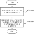
- FIG. 11 is a flowchart illustrating a wireless communication method performed by a user equipment 900 in a wireless communication system according to an embodiment of the present disclosure.
- step S1110 configuration information indicating a transmission beam for transmitting an uplink signal is received.
- step S1120 a transmission beam for transmitting an uplink signal is determined from multiple transmission beams on multiple antenna boards of the user equipment according to the configuration information.
- the multiple antenna boards of the user equipment correspond to the multiple SRS resource sets one-to-one, and one or more transmission beams on each antenna board correspond to the SRS resources in the SRS resource set one-to-one.
- the wireless communication method further includes: determining the SRS resource set indication information and the SRS resource indication information according to the configuration information.
- the wireless communication method further includes: determining, according to the SRS resource set indication information, the SRS resource set where the transmission beam used to send the uplink signal is located; and determining the transmission beam used to send the uplink signal from the SRS resource set according to the SRS resource set information. .
- the wireless communication method further includes: determining, according to the RRC parameters included in the configuration information, a transmission beam corresponding to the RRC parameter as a transmission beam for transmitting an uplink signal.
- the transmission beam corresponding to the RRC parameter represents a transmission beam used by an uplink signal corresponding to the RRC parameter.
- the uplink signal corresponding to the RRC parameter includes at least one of the following: an uplink data signal corresponding to the RRC parameter, an uplink control signal corresponding to the RRC parameter, and an uplink reference signal corresponding to the RRC parameter.
- receiving the configuration information includes: receiving the configuration information through high-level signaling, and the wireless communication method further includes: determining a transmission beam for sending an uplink non-data signal according to the configuration information.
- the uplink non-data signal includes an uplink reference signal and an uplink control signal.
- receiving the configuration information includes receiving the configuration information through low-level signaling, and the wireless communication method further includes determining a transmission beam for sending an uplink data signal according to the configuration information.
- the wireless communication method further includes: performing an uplink beam scanning process for the network-side device to identify multiple transmit beams on multiple antenna boards of the user equipment.
- determining the transmission beam used to send the uplink signal includes: determining one or more transmission beams used to send the uplink signal.
- the subject performing the above method may be the user equipment 900 according to the embodiment of the present disclosure, so all the embodiments of the user equipment 900 in the foregoing are applicable here.
- the technology of the present disclosure can be applied to various products.
- the network-side device can be implemented as any type of TRP.
- the TRP may have sending and receiving functions.
- the TRP may receive information from user equipment and base station equipment, and may also send information to user equipment and base station equipment.
- TRP can provide services to user equipment and is controlled by base station equipment.
- the TRP may have a structure similar to the base station device described below, or may only have a structure related to sending and receiving information in the base station device.
- Network-side equipment can also be implemented as any type of base station equipment, such as macro eNBs and small eNBs, and can also be implemented as any type of gNB.
- a small eNB may be an eNB covering a cell smaller than a macro cell, such as a pico eNB, a pico eNB, and a home (femto) eNB.
- the base station may be implemented as any other type of base station, such as a NodeB and a base transceiver station (BTS).
- the base station may include: a main body (also referred to as a base station device) configured to control wireless communication; and one or more remote wireless headends (RRH) provided at a place different from the main body.
- RRH remote wireless headends
- the user equipment may be implemented as a mobile terminal such as a smartphone, a tablet personal computer (PC), a notebook PC, a portable game terminal, a portable / dongle-type mobile router, and a digital camera device, or a vehicle-mounted terminal such as a car navigation device.
- User equipment can also be implemented as a terminal (also known as a machine type communication (MTC) terminal) that performs machine-to-machine (M2M) communication.
- MTC machine type communication
- M2M machine-to-machine
- the user equipment may be a wireless communication module (such as an integrated circuit module including a single chip) mounted on each of the user equipments described above.
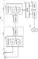
- FIG. 12 is a block diagram showing a first example of a schematic configuration of a gNB to which the technology of the present disclosure can be applied.
- the gNB 1200 includes one or more antennas 1210 and a base station device 1220.
- the base station device 1220 and each antenna 1210 may be connected to each other via an RF cable.
- Each of the antennas 1210 includes a single or multiple antenna elements (such as multiple antenna elements included in a multiple-input multiple-output (MIMO) antenna), and is used for the base station device 1220 to transmit and receive wireless signals.
- the gNB 1200 may include multiple antennas 1210.
- multiple antennas 1210 may be compatible with multiple frequency bands used by gNB 1200.
- FIG. 12 illustrates an example in which the gNB 1200 includes a plurality of antennas 1210, the gNB 1200 may also include a single antenna 1210.
- the base station device 1220 includes a controller 1221, a memory 1222, a network interface 1223, and a wireless communication interface 1225.
- the controller 1221 may be, for example, a CPU or a DSP, and operates various functions of a higher layer of the base station device 1220. For example, the controller 1221 generates a data packet according to data in a signal processed by the wireless communication interface 1225, and transmits the generated packet via the network interface 1223. The controller 1221 may bundle data from multiple baseband processors to generate a bundled packet, and pass the generated bundled packet. The controller 1221 may have a logical function that performs control such as radio resource control, radio bearer control, mobility management, admission control, and scheduling. This control can be performed in conjunction with nearby gNB or core network nodes.
- the memory 1222 includes a RAM and a ROM, and stores a program executed by the controller 1221 and various types of control data such as a terminal list, transmission power data, and scheduling data.
- the network interface 1223 is a communication interface for connecting the base station device 1220 to the core network 1224.
- the controller 1221 may communicate with a core network node or another gNB via the network interface 1223.
- the gNB 1200 and the core network node or other gNBs may be connected to each other through a logical interface such as an S1 interface and an X2 interface.
- the network interface 1223 may also be a wired communication interface or a wireless communication interface for a wireless backhaul line. If the network interface 1223 is a wireless communication interface, compared to the frequency band used by the wireless communication interface 1225, the network interface 1223 can use a higher frequency band for wireless communication.
- the wireless communication interface 1225 supports any cellular communication scheme such as Long Term Evolution (LTE) and LTE-Advanced, and provides a wireless connection to a terminal located in a cell of a gNB 1200 via an antenna 1210.
- the wireless communication interface 1225 may generally include, for example, a baseband (BB) processor 1226 and an RF circuit 1227.
- the BB processor 1226 can perform, for example, encoding / decoding, modulation / demodulation, and multiplexing / demultiplexing, and execute layers (such as L1, Medium Access Control (MAC), Radio Link Control (RLC), and packet data convergence protocols (PDCP)).
- the BB processor 1226 may have a part or all of the above-mentioned logical functions.
- the BB processor 1226 may be a memory storing a communication control program or a module including a processor and related circuits configured to execute the program. Updating the program can change the function of the BB processor 1226.
- the module may be a card or a blade inserted into a slot of the base station device 1220. Alternatively, the module may be a chip mounted on a card or a blade.
- the RF circuit 1227 may include, for example, a mixer, a filter, and an amplifier, and transmits and receives a wireless signal via the antenna 1210.
- the wireless communication interface 1225 may include a plurality of BB processors 1226.
- multiple BB processors 1226 may be compatible with multiple frequency bands used by gNB 1200.
- the wireless communication interface 1225 may include a plurality of RF circuits 1227.
- multiple RF circuits 1227 may be compatible with multiple antenna elements.
- FIG. 12 illustrates an example in which the wireless communication interface 1225 includes a plurality of BB processors 1226 and a plurality of RF circuits 1227, the wireless communication interface 1225 may also include a single BB processor 1226 or a single RF circuit 1227.
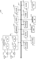
- FIG. 13 is a block diagram showing a second example of a schematic configuration of a gNB to which the technology of the present disclosure can be applied.
- the gNB 1330 includes one or more antennas 1340, base station equipment 1350, and RRH 1360.
- the RRH 1360 and each antenna 1340 may be connected to each other via an RF cable.
- the base station equipment 1350 and the RRH 1360 may be connected to each other via a high-speed line such as a fiber optic cable.
- Each of the antennas 1340 includes a single or multiple antenna elements (such as multiple antenna elements included in a MIMO antenna) and is used for RRH 1360 to transmit and receive wireless signals.
- the gNB 1330 may include multiple antennas 1340.
- multiple antennas 1340 may be compatible with multiple frequency bands used by gNB 1330.
- FIG. 13 shows an example in which the gNB 1330 includes a plurality of antennas 1340, the gNB 1330 may also include a single antenna 1340.
- the base station device 1350 includes a controller 1351, a memory 1352, a network interface 1353, a wireless communication interface 1355, and a connection interface 1357.
- the controller 1351, the memory 1352, and the network interface 1353 are the same as the controller 1221, the memory 1222, and the network interface 1223 described with reference to FIG.
- the wireless communication interface 1355 supports any cellular communication scheme such as LTE and LTE-Advanced, and provides wireless communication to terminals located in a sector corresponding to RRH 1360 via RRH 1360 and antenna 1340.
- the wireless communication interface 1355 may generally include, for example, a BB processor 1356.
- the BB processor 1356 is the same as the BB processor 1226 described with reference to FIG. 12 except that the BB processor 1356 is connected to the RF circuit 1364 of the RRH 1360 via the connection interface 1357.
- the wireless communication interface 1355 may include a plurality of BB processors 1356.
- multiple BB processors 1356 may be compatible with multiple frequency bands used by gNB 1330.
- FIG. 13 shows an example in which the wireless communication interface 1355 includes a plurality of BB processors 1356, the wireless communication interface 1355 may include a single BB processor 1356.
- connection interface 1357 is an interface for connecting the base station device 1350 (wireless communication interface 1355) to the RRH 1360.
- the connection interface 1357 may also be a communication module for communication in the above-mentioned high-speed line connecting the base station device 1350 (wireless communication interface 1355) to the RRH 1360.
- the RRH 1360 includes a connection interface 1361 and a wireless communication interface 1363.
- connection interface 1361 is an interface for connecting the RRH 1360 (wireless communication interface 1363) to the base station device 1350.
- the connection interface 1361 may also be a communication module for communication in the above-mentioned high-speed line.
- the wireless communication interface 1363 transmits and receives wireless signals via the antenna 1340.
- the wireless communication interface 1363 may generally include, for example, an RF circuit 1364.
- the RF circuit 1364 may include, for example, a mixer, a filter, and an amplifier, and transmits and receives wireless signals via the antenna 1340.
- the wireless communication interface 1363 may include a plurality of RF circuits 1364.
- multiple RF circuits 1364 may support multiple antenna elements.
- FIG. 13 shows an example in which the wireless communication interface 1363 includes a plurality of RF circuits 1364, the wireless communication interface 1363 may also include a single RF circuit 1364.
- the configuration unit 210 and the generation unit 220 described in FIG. 2 may be implemented by the controller 1221 and / or the controller 1351. At least a part of the functions may also be implemented by the controller 1221 and the controller 1351.
- the controller 1221 and / or the controller 1351 may perform a function of configuring a transmission beam for transmitting an uplink signal and generating configuration information by executing instructions stored in a corresponding memory.
- FIG. 14 is a block diagram showing an example of a schematic configuration of a smartphone 1400 to which the technology of the present disclosure can be applied.
- the smart phone 1400 includes a processor 1401, a memory 1402, a storage device 1403, an external connection interface 1404, a camera device 1406, a sensor 1407, a microphone 1408, an input device 1409, a display device 1410, a speaker 1411, a wireless communication interface 1412, one or more An antenna switch 1415, one or more antennas 1416, a bus 1417, a battery 1418, and an auxiliary controller 1419.
- the processor 1401 may be, for example, a CPU or a system on chip (SoC), and controls functions of an application layer and another layer of the smartphone 1400.
- the memory 1402 includes a RAM and a ROM, and stores data and programs executed by the processor 1401.
- the storage device 1403 may include a storage medium such as a semiconductor memory and a hard disk.
- the external connection interface 1404 is an interface for connecting external devices such as a memory card and a universal serial bus (USB) device to the smartphone 1400.
- the imaging device 1406 includes an image sensor such as a charge-coupled device (CCD) and a complementary metal oxide semiconductor (CMOS), and generates a captured image.
- the sensor 1407 may include a set of sensors such as a measurement sensor, a gyroscope sensor, a geomagnetic sensor, and an acceleration sensor.
- the microphone 1408 converts a sound input to the smartphone 1400 into an audio signal.
- the input device 1409 includes, for example, a touch sensor, a keypad, a keyboard, a button, or a switch configured to detect a touch on the screen of the display device 1410, and receives an operation or information input from a user.
- the display device 1410 includes a screen such as a liquid crystal display (LCD) and an organic light emitting diode (OLED) display, and displays an output image of the smartphone 1400.
- the speaker 1411 converts an audio signal output from the smartphone 1400 into a sound.
- the wireless communication interface 1412 supports any cellular communication scheme such as LTE and LTE-Advanced, and performs wireless communication.
- the wireless communication interface 1412 may generally include, for example, a BB processor 1413 and an RF circuit 1414.
- the BB processor 1413 may perform, for example, encoding / decoding, modulation / demodulation, and multiplexing / demultiplexing, and perform various types of signal processing for wireless communication.
- the RF circuit 1414 may include, for example, a mixer, a filter, and an amplifier, and transmits and receives a wireless signal via the antenna 1416.
- the wireless communication interface 1412 may be a chip module on which a BB processor 1413 and an RF circuit 1414 are integrated. As shown in FIG.
- the wireless communication interface 1412 may include multiple BB processors 1413 and multiple RF circuits 1414.
- FIG. 14 shows an example in which the wireless communication interface 1412 includes a plurality of BB processors 1413 and a plurality of RF circuits 1414, the wireless communication interface 1412 may also include a single BB processor 1413 or a single RF circuit 1414.
- the wireless communication interface 1412 may support another type of wireless communication scheme, such as a short-range wireless communication scheme, a near field communication scheme, and a wireless local area network (LAN) scheme.
- the wireless communication interface 1412 may include a BB processor 1413 and an RF circuit 1414 for each wireless communication scheme.
- Each of the antenna switches 1415 switches a connection destination of the antenna 1416 between a plurality of circuits included in the wireless communication interface 1412 (for example, circuits for different wireless communication schemes).
- Each of the antennas 1416 includes a single or multiple antenna elements, such as multiple antenna elements included in a MIMO antenna, and is used for the wireless communication interface 1412 to transmit and receive wireless signals.
- the smartphone 1400 may include a plurality of antennas 1416.
- FIG. 14 shows an example in which the smartphone 1400 includes a plurality of antennas 1416, the smartphone 1400 may include a single antenna 1416.
- the smartphone 1400 may include an antenna 1416 for each wireless communication scheme.
- the antenna switch 1415 may be omitted from the configuration of the smartphone 1400.
- the bus 1417 connects the processor 1401, the memory 1402, the storage device 1403, the external connection interface 1404, the camera 1406, the sensor 1407, the microphone 1408, the input device 1409, the display device 1410, the speaker 1411, the wireless communication interface 1412, and the auxiliary controller 1419 to each other. connection.
- the battery 1418 supplies power to each block of the smartphone 1400 shown in FIG. 14 via a feeder, and the feeder is partially shown as a dotted line in the figure.
- the auxiliary controller 1419 operates the minimum necessary functions of the smartphone 1400 in the sleep mode, for example.
- the determination unit 920 and the scanning unit 930 described by using FIG. 9 may be implemented by the processor 1401 or the auxiliary controller 1419. At least a part of the functions may also be implemented by the processor 1401 or the auxiliary controller 1419.
- the processor 1401 or the auxiliary controller 1419 may execute functions stored in the memory 1402 or the storage device 1403 to determine a transmission beam for transmitting an uplink signal and perform an uplink beam scan function.
- FIG. 15 is a block diagram showing an example of a schematic configuration of a car navigation device 1520 to which the technology of the present disclosure can be applied.
- the car navigation device 1520 includes a processor 1521, a memory 1522, a global positioning system (GPS) module 1524, a sensor 1525, a data interface 1526, a content player 1527, a storage medium interface 1528, an input device 1529, a display device 1530, a speaker 1531, and a wireless
- GPS global positioning system
- the processor 1521 may be, for example, a CPU or a SoC, and controls navigation functions and other functions of the car navigation device 1520.
- the memory 1522 includes a RAM and a ROM, and stores data and programs executed by the processor 1521.
- the GPS module 1524 uses a GPS signal received from a GPS satellite to measure the position (such as latitude, longitude, and altitude) of the car navigation device 1520.
- the sensor 1525 may include a set of sensors such as a gyroscope sensor, a geomagnetic sensor, and an air pressure sensor.
- the data interface 1526 is connected to, for example, an in-vehicle network 1541 via a terminal not shown, and acquires data (such as vehicle speed data) generated by the vehicle.
- the content player 1527 reproduces content stored in a storage medium such as a CD and a DVD, which is inserted into the storage medium interface 1528.
- the input device 1529 includes, for example, a touch sensor, a button, or a switch configured to detect a touch on the screen of the display device 1530, and receives an operation or information input from a user.
- the display device 1530 includes a screen such as an LCD or OLED display, and displays an image of a navigation function or reproduced content.
- the speaker 1531 outputs the sound of the navigation function or the reproduced content.
- the wireless communication interface 1533 supports any cellular communication scheme such as LTE and LTE-Advanced, and performs wireless communication.
- the wireless communication interface 1533 may generally include, for example, a BB processor 1534 and an RF circuit 1535.
- the BB processor 1534 can perform, for example, encoding / decoding, modulation / demodulation, and multiplexing / demultiplexing, and perform various types of signal processing for wireless communication.
- the RF circuit 1535 may include, for example, a mixer, a filter, and an amplifier, and transmit and receive wireless signals via the antenna 1537.
- the wireless communication interface 1533 may also be a chip module on which a BB processor 1534 and an RF circuit 1535 are integrated. As shown in FIG.
- the wireless communication interface 1533 may include multiple BB processors 1534 and multiple RF circuits 1535.
- FIG. 15 shows an example in which the wireless communication interface 1533 includes a plurality of BB processors 1534 and a plurality of RF circuits 1535, the wireless communication interface 1533 may also include a single BB processor 1534 or a single RF circuit 1535.
- the wireless communication interface 1533 may support another type of wireless communication scheme, such as a short-range wireless communication scheme, a near-field communication scheme, and a wireless LAN scheme.
- the wireless communication interface 1533 may include a BB processor 1534 and an RF circuit 1535 for each wireless communication scheme.
- Each of the antenna switches 1536 switches a connection destination of the antenna 1537 between a plurality of circuits included in the wireless communication interface 1533, such as circuits for different wireless communication schemes.
- Each of the antennas 1537 includes a single or multiple antenna elements (such as multiple antenna elements included in a MIMO antenna), and is used for the wireless communication interface 1533 to transmit and receive wireless signals.
- the car navigation device 1520 may include a plurality of antennas 1537.
- FIG. 15 shows an example in which the car navigation device 1520 includes a plurality of antennas 1537, the car navigation device 1520 may also include a single antenna 1537.
- the car navigation device 1520 may include an antenna 1537 for each wireless communication scheme.
- the antenna switch 1536 may be omitted from the configuration of the car navigation device 1520.
- the battery 1538 supplies power to each block of the car navigation device 1520 shown in FIG. 15 via a feeder, and the feeder is partially shown as a dotted line in the figure.
- the battery 1538 accumulates power provided from the vehicle.
- the determination unit 920 and the scanning unit 930 described by using FIG. 9 may be implemented by the processor 1521. At least a part of the functions may also be implemented by the processor 1521.
- the processor 1521 may perform functions of determining a transmission beam for transmitting an uplink signal and performing an uplink beam scan by executing instructions stored in the memory 1522.
- the technology of the present disclosure may also be implemented as an in-vehicle system (or vehicle) 1540 including one or more of a car navigation device 1520, an in-vehicle network 1541, and a vehicle module 1542.
- vehicle module 1542 generates vehicle data such as vehicle speed, engine speed, and failure information, and outputs the generated data to the in-vehicle network 1541.
- the units shown by dashed boxes in the functional block diagram shown in the drawings all indicate that the functional unit is optional in the corresponding device, and each optional functional unit can be combined in an appropriate manner to achieve the required function .
- a plurality of functions included in one unit in the above embodiments may be implemented by separate devices.
- multiple functions implemented by multiple units in the above embodiments may be implemented by separate devices, respectively.
- one of the above functions may be implemented by multiple units. Needless to say, such a configuration is included in the technical scope of the present disclosure.
- the steps described in the flowchart include not only processes performed in time series in the described order, but also processes performed in parallel or individually instead of having to be performed in time series. Further, even in the steps processed in a time series, needless to say, the order can be appropriately changed.
Landscapes
- Engineering & Computer Science (AREA)
- Signal Processing (AREA)
- Computer Networks & Wireless Communication (AREA)
- Power Engineering (AREA)
- Mobile Radio Communication Systems (AREA)
Abstract
Description
本申请要求于2018年9月26日提交中国专利局、申请号为201811123667.5、发明名称为“网络侧设备、用户设备、无线通信方法和存储介质”的中国专利申请的优先权,其全部内容通过引用结合在本申请中。This application claims the priority of a Chinese patent application filed on September 26, 2018 with the Chinese Patent Office, application number 201811123667.5, and the invention name is "network-side equipment, user equipment, wireless communication method, and storage medium". Citations are incorporated in this application.
本公开的实施例总体上涉及无线通信领域,具体地涉及网络侧设备、用户设备、无线通信方法和计算机可读存储介质。更具体地,本公开涉及一种无线通信系统中的网络侧设备、一种无线通信系统中的用户设备、一种由无线通信系统中的网络侧设备执行的无线通信方法、一种由无线通信系统中的用户设备执行的无线通信方法以及一种计算机可读存储介质。Embodiments of the present disclosure generally relate to the field of wireless communications, and in particular, to a network-side device, a user equipment, a wireless communication method, and a computer-readable storage medium. More specifically, the present disclosure relates to a network-side device in a wireless communication system, a user equipment in the wireless communication system, a wireless communication method performed by the network-side device in the wireless communication system, and a wireless communication A wireless communication method performed by user equipment in the system and a computer-readable storage medium.
波束赋形是一种基于天线阵列的信号预处理技术,波束赋形通过调整天线阵列中每个阵元的加权系数产生具有指向性的波束,从而能够获得明显的阵列增益。因此,波束赋形技术在扩大覆盖范围、改善边缘吞吐量以及干扰抑止等方面都有很大的优势。在采用波束赋形技术的上行传输中,网络侧设备可以为用户设备选取合适的上行发射波束并向用户设备通知该选取的上行发射波束,从而使得用户设备可以利用网络侧设备选取的上行发射波束来发送上行信号。Beamforming is a signal preprocessing technology based on an antenna array. Beamforming can produce a directional beam by adjusting the weighting coefficients of each array element in the antenna array, thereby obtaining a significant array gain. Therefore, beamforming technology has great advantages in terms of expanding coverage, improving edge throughput, and interference suppression. In uplink transmission using beamforming technology, the network side device can select a suitable uplink transmission beam for the user equipment and notify the user equipment of the selected uplink transmission beam, so that the user equipment can use the uplink transmission beam selected by the network side device. To send uplink signals.
在最近的研究中,提出了用户设备可以配备有多个天线板的配置,每个天线板都可以独立地打出多个波束方向。也就是说,每个天线板在一个OFDM(Orthogonal Frequency Division Multiplexing,正交频分复用)符号或者一个时隙上仅可以打出一个波束方向,而在一个OFDM符号或者一个时隙上不同的天线板可以独立地打出各自的波束方向。在这种情况下,现有的通信标准不能适用于用户设备配备有多个天线板的配置。也就是说,在用户设备配备有多个天线板的情况下,网络侧设备如何向用户设备通知选取的上行发射波束是亟待解决的技术问题之一。In a recent study, a configuration is proposed in which user equipment can be equipped with multiple antenna boards, and each antenna board can independently strike multiple beam directions. That is, each antenna board can only play one beam direction on one OFDM (Orthogonal Frequency Division Multiplexing) symbol or one time slot, and different antennas on one OFDM symbol or one time slot The boards can independently hit their respective beam directions. In this case, the existing communication standard cannot be applied to a configuration in which the user equipment is equipped with multiple antenna boards. That is, when the user equipment is equipped with multiple antenna boards, how the network-side device notifies the user equipment of the selected uplink transmission beam is one of the technical problems to be solved urgently.
因此,有必要提出一种技术方案,以使得网络侧设备能够在用户设备配备有多个天线板的情况下向用户设备通知选取的上行发射波束,从而 优化上行发射波束的确定过程。Therefore, it is necessary to propose a technical solution so that the network-side device can notify the user equipment of the selected uplink transmission beam if the user equipment is equipped with multiple antenna boards, thereby optimizing the determination process of the uplink transmission beam.
发明内容Summary of the Invention
这个部分提供了本公开的一般概要,而不是其全部范围或其全部特征的全面披露。This section provides a general summary of the disclosure, rather than a comprehensive disclosure of its full scope or all of its features.
本公开的目的在于提供一种网络侧设备、用户设备、无线通信方法和存储介质,以使得网络侧设备能够在用户设备配备有多个天线板的情况下向用户设备通知选取的上行发射波束,从而优化上行发射波束的确定过程。An object of the present disclosure is to provide a network-side device, user equipment, wireless communication method, and storage medium, so that the network-side device can notify the user equipment of the selected uplink transmission beam if the user equipment is equipped with multiple antenna boards, Thereby, the determination process of the uplink transmission beam is optimized.
根据本公开的一方面,提供了一种网络侧设备,包括处理电路,被配置为:从用户设备的多个天线板上的多个发射波束中为所述用户设备配置用于发送上行信号的发射波束;以及生成配置信息,所述配置信息指示用于发送上行信号的发射波束。According to an aspect of the present disclosure, there is provided a network-side device including a processing circuit configured to configure the user equipment from a plurality of transmit beams on multiple antenna boards of the user equipment for sending an uplink signal. Transmitting a beam; and generating configuration information that indicates a transmitting beam for transmitting an uplink signal.
根据本公开的另一方面,提供了一种用户设备,包括处理电路,被配置为:接收指示用于发送上行信号的发射波束的配置信息;以及根据所述配置信息从所述用户设备的多个天线板上的多个发射波束中确定用于发送上行信号的发射波束。According to another aspect of the present disclosure, there is provided a user equipment including a processing circuit configured to: receive configuration information indicating a transmission beam used to transmit an uplink signal; and from a plurality of the user equipment according to the configuration information. A transmission beam for transmitting an uplink signal is determined from a plurality of transmission beams on the antenna boards.
根据本公开的另一方面,提供了一种由网络侧设备执行的无线通信方法,包括:从用户设备的多个天线板上的多个发射波束中为所述用户设备配置用于发送上行信号的发射波束;以及生成配置信息,所述配置信息指示用于发送上行信号的发射波束。According to another aspect of the present disclosure, there is provided a wireless communication method performed by a network-side device, including: configuring the user equipment from multiple transmit beams on multiple antenna boards of a user equipment to send an uplink signal. A transmission beam; and generating configuration information that indicates a transmission beam used to send an uplink signal.
根据本公开的另一方面,提供了一种由用户设备执行的无线通信方法,包括:接收指示用于发送上行信号的发射波束的配置信息;以及根据所述配置信息从所述用户设备的多个天线板上的多个发射波束中确定用于发送上行信号的发射波束。According to another aspect of the present disclosure, there is provided a wireless communication method performed by a user equipment, including: receiving configuration information indicating a transmission beam used to transmit an uplink signal; and from a plurality of the user equipment according to the configuration information. A transmission beam for transmitting an uplink signal is determined from a plurality of transmission beams on the antenna boards.
根据本公开的另一方面,提供了一种计算机可读存储介质,包括可执行计算机指令,所述可执行计算机指令当被计算机执行时使得所述计算机执行根据本公开所述的无线通信方法。According to another aspect of the present disclosure, there is provided a computer-readable storage medium including executable computer instructions that, when executed by a computer, cause the computer to perform the wireless communication method according to the present disclosure.
使用根据本公开的网络侧设备、用户设备、无线通信方法和计算机可读存储介质,使得网络侧设备能够从用户设备的多个天线板上的多个发射波束中为用户设备配置用于发送上行信号的发射波束,并能够生成指示 该配置的发射波束的配置信息。这样一来,网络侧设备能够在用户设备配备有多个天线板的情况下向用户设备通知选取的上行发射波束,从而优化上行发射波束的确定过程。Using the network-side device, user equipment, wireless communication method, and computer-readable storage medium according to the present disclosure enables the network-side device to configure the user equipment from multiple transmission beams on multiple antenna boards of the user equipment for sending uplink The transmission beam of the signal, and can generate configuration information indicating the configured transmission beam. In this way, the network-side device can notify the user equipment of the selected uplink transmission beam when the user equipment is equipped with multiple antenna boards, thereby optimizing the determination process of the uplink transmission beam.
从在此提供的描述中,进一步的适用性区域将会变得明显。这个概要中的描述和特定例子只是为了示意的目的,而不旨在限制本公开的范围。Further areas of applicability will become apparent from the description provided herein. The descriptions and specific examples in this summary are for illustrative purposes only and are not intended to limit the scope of the disclosure.
在此描述的附图只是为了所选实施例的示意的目的而非全部可能的实施,并且不旨在限制本公开的范围。在附图中:The drawings described herein are for illustrative purposes of selected embodiments and not all possible implementations, and are not intended to limit the scope of the disclosure. In the drawings:
图1是示出现有技术中选取用于发送上行数据信号的发射波束的过程的示意图;FIG. 1 is a schematic diagram illustrating a process of selecting a transmission beam for transmitting an uplink data signal in the prior art;
图2是示出根据本公开的实施例的网络侧设备的配置的示例的框图;2 is a block diagram showing an example of a configuration of a network-side device according to an embodiment of the present disclosure;
图3是示出根据本公开的实施例的发射波束与SRS(Sounding Reference Signal,测量参考信号)资源的映射关系的示意图;3 is a schematic diagram showing a mapping relationship between a transmission beam and an SRS (Sounding Reference Signal) resource according to an embodiment of the present disclosure;
图4(a)是示出根据本公开的实施例的指示发送上行数据信号的发射波束的配置信息的示意图;4 (a) is a schematic diagram illustrating configuration information of a transmission beam indicating transmission of an uplink data signal according to an embodiment of the present disclosure;
图4(b)是示出根据本公开的实施例的指示发送上行数据信号的发射波束的配置信息的示意图;4 (b) is a schematic diagram illustrating configuration information of a transmission beam indicating transmission of an uplink data signal according to an embodiment of the present disclosure;
图5是示出根据本公开的实施例的SpatialRelationInfo参数的内容的示意图;5 is a schematic diagram showing contents of a SpatialRelationInfo parameter according to an embodiment of the present disclosure;
图6(a)是示出根据本公开的实施例的指示发送上行数据信号的发射波束的配置信息的示意图;6 (a) is a schematic diagram illustrating configuration information of a transmission beam indicating transmission of an uplink data signal according to an embodiment of the present disclosure;
图6(b)是示出根据本公开的实施例的指示发送上行数据信号的发射波束的配置信息的示意图;6 (b) is a schematic diagram showing configuration information of a transmission beam indicating transmission of an uplink data signal according to an embodiment of the present disclosure;
图6(c)是示出根据本公开的实施例的指示发送上行数据信号的发射波束的配置信息的示意图;6 (c) is a schematic diagram illustrating configuration information of a transmission beam indicating transmission of an uplink data signal according to an embodiment of the present disclosure;
图6(d)是示出根据本公开的实施例的指示发送上行数据信号的发射波束的配置信息的示意图;6 (d) is a schematic diagram illustrating configuration information of a transmission beam indicating transmission of an uplink data signal according to an embodiment of the present disclosure;
图6(e)是示出根据本公开的实施例的指示发送上行数据信号的发 射波束的配置信息的示意图;6 (e) is a schematic diagram illustrating configuration information of a transmission beam indicating transmission of an uplink data signal according to an embodiment of the present disclosure;
图7是示出根据本公开的实施例的选取用于发送上行数据信号的发射波束的过程的示意图;7 is a schematic diagram illustrating a process of selecting a transmission beam for transmitting an uplink data signal according to an embodiment of the present disclosure;
图8是示出根据本公开的实施例的选取用于发送上行数据信号的发射波束的信令流程图;8 is a signaling flowchart illustrating selection of a transmission beam for transmitting an uplink data signal according to an embodiment of the present disclosure;
图9是示出根据本公开的实施例的用户设备的配置的示例的框图;9 is a block diagram showing an example of a configuration of a user equipment according to an embodiment of the present disclosure;
图10是示出根据本公开的实施例的由网络侧设备执行的无线通信方法的流程图;10 is a flowchart illustrating a wireless communication method performed by a network-side device according to an embodiment of the present disclosure;
图11是示出根据本公开的实施例的由用户设备执行的无线通信方法的流程图;11 is a flowchart illustrating a wireless communication method performed by a user equipment according to an embodiment of the present disclosure;
图12是示出gNB(5G通信系统中的基站设备)的示意性配置的第一示例的框图;12 is a block diagram showing a first example of a schematic configuration of a gNB (base station device in a 5G communication system);
图13是示出gNB的示意性配置的第二示例的框图;13 is a block diagram showing a second example of a schematic configuration of a gNB;
图14是示出智能电话的示意性配置的示例的框图;以及FIG. 14 is a block diagram showing an example of a schematic configuration of a smartphone; and
图15是示出汽车导航设备的示意性配置的示例的框图。FIG. 15 is a block diagram showing an example of a schematic configuration of a car navigation device.
虽然本公开容易经受各种修改和替换形式,但是其特定实施例已作为例子在附图中示出,并且在此详细描述。然而应当理解的是,在此对特定实施例的描述并不打算将本公开限制到公开的具体形式,而是相反地,本公开目的是要覆盖落在本公开的精神和范围之内的所有修改、等效和替换。要注意的是,贯穿几个附图,相应的标号指示相应的部件。Although the present disclosure is susceptible to various modifications and alternative forms, specific embodiments thereof have been shown by way of example in the drawings and are described in detail herein. It should be understood, however, that the description of specific embodiments herein is not intended to limit the present disclosure to the specific forms disclosed, but rather, the purpose of the present disclosure is to cover all that falls within the spirit and scope of the present disclosure. Modifications, equivalents, and replacements. It is to be noted that throughout the several figures, corresponding reference numerals indicate corresponding parts.
现在参考附图来更加充分地描述本公开的例子。以下描述实质上只是示例性的,而不旨在限制本公开、应用或用途。Examples of the present disclosure will now be described more fully with reference to the accompanying drawings. The following description is merely exemplary in nature and is not intended to limit the present disclosure, application, or uses.
提供了示例实施例,以便本公开将会变得详尽,并且将会向本领域技术人员充分地传达其范围。阐述了众多的特定细节如特定部件、装置和方法的例子,以提供对本公开的实施例的详尽理解。对于本领域技术人员而言将会明显的是,不需要使用特定的细节,示例实施例可以用许多不同的形式来实施,它们都不应当被解释为限制本公开的范围。在某些示例实施例中,没有详细地描述众所周知的过程、众所周知的结构和众所周知的 技术。Example embodiments are provided so that this disclosure will be thorough, and will fully convey its scope to those skilled in the art. Numerous specific details are set forth, such as examples of specific components, devices, and methods, to provide a thorough understanding of embodiments of the present disclosure. It will be apparent to those skilled in the art that specific details need not be used, that example embodiments may be implemented in many different forms, and they should not be construed as limiting the scope of the disclosure. In some example embodiments, well-known processes, well-known structures, and well-known technologies are not described in detail.
将按照以下顺序进行描述:It will be described in the following order:
1.问题的描述;1. a description of the problem;
2.网络侧设备的配置示例;2. Configuration example of network side equipment;
3.用户设备的配置示例;3. Configuration example of user equipment;
4.方法实施例;4. Method embodiments;
5.应用示例。5. Application examples.
<1.问题的描述><1. Description of the problem>
在3GPP标准的Release15版本中,UE(User Equipment,用户设备)的多个天线板与多个SRS资源集合一一对应,并且UE的多个发射波束中的每一个对应一个SRS资源。进一步,基站可以为UE配置多个SRS资源集合,不同的SRS资源集合可以有不同的目的。也就是说,UE的不同天线板上的波束可以具有不同的目的,而位于同一个天线板上的波束具有相同的目的。在目前的标准中定义了四种目的,分别是波束管理(beam management)、基于码本(codebook)传输的CSI(Channel State Information,信道状态信息)获取、基于非码本(non-codebook)传输的CSI获取和天线切换(antenna switch)。可以针对每一个SRS资源集合来配置四种目的中的一种。在标准中相关的代码如下:In the Release 15 version of the 3GPP standard, multiple antenna boards of a UE (User Equipment) correspond to one or more SRS resource sets, and each of multiple transmit beams of the UE corresponds to one SRS resource. Further, the base station may configure multiple SRS resource sets for the UE, and different SRS resource sets may have different purposes. That is, the beams on different antenna boards of the UE may have different purposes, while the beams located on the same antenna board have the same purpose. In the current standard, four purposes are defined, which are beam management, channel-state information (CSI) acquisition based on codebook (CSI) transmission, and non-codebook-based transmission. CSI acquisition and antenna switching. One of four purposes can be configured for each SRS resource set. The relevant code in the standard is as follows:
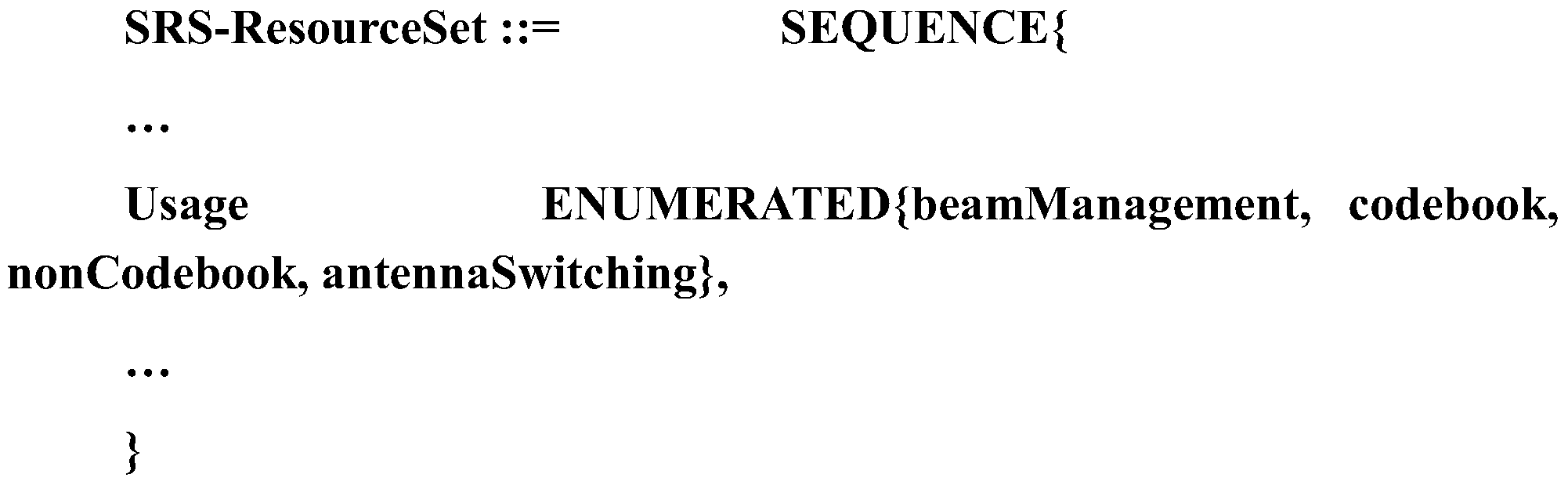
其中,Usage表示该SRS资源集合的目的,选自波束管理、基于码本传输的CSI获取、基于非码本传输的CSI获取和天线切换中的任何一种。Where, Usage indicates the purpose of the SRS resource set and is selected from any one of beam management, CSI acquisition based on codebook transmission, CSI acquisition based on non-codebook transmission, and antenna switching.
图1是示出现有技术中选取用于发送上行数据信号的发射波束的过程的示意图。FIG. 1 is a schematic diagram illustrating a process of selecting a transmission beam for transmitting an uplink data signal in the prior art.
在3GPP标准的Release 15版本中,定义了上行波束选择过程包括 基于SRS的波束扫描、RRC(Radio Resource Control,无线资源控制)配置和进行SRS资源指示的三个步骤。In the Release 15 version of the 3GPP standard, the uplink beam selection process is defined to include three steps of SRS-based beam scanning, RRC (Radio Resource Control) configuration, and SRS resource indication.
如图1所示,首先,gNB通过RRC信令向UE配置用于波束管理的SRS资源集合。接下来,UE可以基于gNB的配置执行上行波束扫描过程。接下来,基于UE的上行波束扫描过程,gNB可以测量获取到的波束的质量,例如测量RSRP(Reference Signal Receiving Power,参考信号接收功率),从而选择出最好的上行发射波束。进一步,基站可以通过RRC信令为UE配置基于码本传输的CSI获取或者基于非码本传输的CSI获取的SRS资源集合,并为每个资源集合中的每个SRS资源配置发射波束。接下来,UE可以基于gNB的再次配置执行SRS波束发送以辅助基站获取上行CSI,这里UE可以利用基于码本传输的CSI获取的SRS资源或者利用基于非码本传输的CSI获取的SRS资源来执行SRS波束发送以辅助基站获取CSI。需要说明的是,对于半静态的SRS,gNB还需要进一步通过MAC CE(Media Access Control Control Element,媒体接入控制控制单元)来激活多个半静态SRS波束中的一个SRS波束。接下来,gNB在进行必要的测量后,通过DCI(Downlink Control Information,下行控制信息)信令中的SRI(SRS Resource Indicator,SRS资源指示)来向UE通知选取的用于发送上行信号的发射波束。这里,gNB可以向UE指示在最近的时隙中使用的基于码本传输的CSI获取的SRS资源集合或者利用基于非码本传输的CSI获取的SRS资源集合中的一个SRS资源。接下来,UE可以利用gNB指示的SRS资源所对应的波束来进行上行数据传输,即发送PUSCH(Physical Uplink Shared Channel,物理上行共享信道)信号。As shown in FIG. 1, first, the gNB configures an SRS resource set for beam management to the UE through RRC signaling. Next, the UE may perform an uplink beam scanning process based on the configuration of the gNB. Next, based on the UE's uplink beam scanning process, the gNB can measure the quality of the acquired beams, such as measuring RSRP (Reference Signaling and Receiving Power) to select the best uplink transmitting beam. Further, the base station can configure the SRS resource set based on codebook transmission or non-codebook based CSI acquisition for the UE through RRC signaling, and configure a transmission beam for each SRS resource in each resource set. Next, the UE may perform SRS beam transmission based on the reconfiguration of the gNB to assist the base station to obtain uplink CSI. Here, the UE may perform the SRS resource obtained by the CSI based on codebook transmission or the SRS resource obtained by the CSI based on non-codebook transmission. The SRS beam is transmitted to assist the base station in obtaining the CSI. It should be noted that, for the semi-static SRS, the gNB needs to further activate one SRS beam among the multiple semi-static SRS beams through a MAC CE (Media Access Control Control Element). Next, after performing the necessary measurements, the gNB notifies the UE of the selected transmission beam for sending uplink signals through SRI (SRS Resource Indicator) in DCI (Downlink Control Information) signaling. . Here, the gNB may indicate to the UE an SRS resource set obtained by using CSI based on codebook transmission in the most recent time slot or one SRS resource in the set of SRS resources obtained by using CSI based on non-codebook transmission. Next, the UE can use the beam corresponding to the SRS resource indicated by the gNB to perform uplink data transmission, that is, send a PUSCH (Physical Uplink Shared Channel) signal.
由图1可见,在现有的上行发射波束选择过程中,gNB需要通过RRC信令为UE配置两次SRS资源集合,第一次是配置用于波束管理的SRS资源集合,第二次是配置用于CSI获取的SRS资源集合,这无疑增加了信令开销。同时,如果UE在小区内移动,则两次配置必然导致配置的不准确性并可能引起不必要的RRC重配置。进一步,对于半静态的SRS,gNB还需要进一步通过MAC CE来激活多个半静态SRS波束中的一个SRS波束,这进一步增加了信令开销和过程的复杂性。此外,在通过DCI指示的过程中,DCI指示的是基于码本传输的CSI获取的SRS资源集合或者基于非码本传输的CSI获取的SRS资源集合中的一个SRS资源,没有考虑UE的天线板信息。It can be seen from FIG. 1 that in the existing uplink transmission beam selection process, the gNB needs to configure the SRS resource set for the UE twice through RRC signaling, the first time is to configure the SRS resource set for beam management, and the second is to configure The set of SRS resources used for CSI acquisition, which undoubtedly increases the signaling overhead. At the same time, if the UE moves in the cell, the two configurations will inevitably lead to inaccurate configuration and may cause unnecessary RRC reconfiguration. Further, for semi-static SRS, gNB needs to further activate one SRS beam among multiple semi-static SRS beams through MAC CE, which further increases the signaling overhead and the complexity of the process. In addition, in the process of DCI indication, DCI indicates an SRS resource set in the SRS resource set acquired based on CSI transmitted through codebook or an SRS resource set acquired based on CSI transmitted in non-codebook, without considering the antenna plate of the UE. information.
对于上行传输控制存在类似的问题,即gNB在向UE配置用于发送上行非数据信号的发射波束时没有考虑UE的天线板信息。There is a similar problem for uplink transmission control, that is, the gNB does not consider the antenna board information of the UE when it configures the UE with a transmit beam for sending uplink non-data signals.
本公开针对这样的场景提出了一种无线通信系统中的网络侧设备、用户设备、由无线通信系统中的网络侧设备执行的无线通信方法、由无线通信系统中的用户设备执行的无线通信方法以及计算机可读存储介质,以使得网络侧设备能够在用户设备配备有多个天线板的情况下向用户设备通知选取的上行发射波束,简化上行发射波束的确定过程,减小信令开销和系统时延。The present disclosure proposes a network-side device, a user equipment in a wireless communication system, a wireless communication method performed by a network-side device in a wireless communication system, and a wireless communication method performed by a user equipment in a wireless communication system. And a computer-readable storage medium, so that the network-side device can notify the user equipment of the selected uplink transmission beam if the user equipment is equipped with multiple antenna boards, simplify the determination process of the uplink transmission beam, and reduce signaling overhead and system Delay.
根据本公开的网络侧设备可以是任何类型的TRP(Transmit and Receive Port,发送和接收端口)。该TRP可以具备发送和接收功能,例如可以从用户设备和基站设备接收信息,也可以向用户设备和基站设备发送信息。在一个示例中,TRP可以为用户设备提供服务,并且受基站设备的控制。也就是说,基站设备通过TRP向用户设备提供服务。此外,在本公开中所述的网络侧设备也可以是基站设备,例如可以是eNB(演进型节点B),也可以是gNB。The network-side device according to the present disclosure may be any type of TRP (Transmit and Receive Port). The TRP may have sending and receiving functions. For example, the TRP may receive information from user equipment and base station equipment, and may also send information to user equipment and base station equipment. In one example, the TRP may serve user equipment and is controlled by the base station equipment. That is, the base station device provides services to the user equipment through TRP. In addition, the network-side device described in the present disclosure may also be a base station device, such as an eNB (evolved node B), or a gNB.
根据本公开的用户设备可以是移动终端(诸如智能电话、平板个人计算机(PC)、笔记本式PC、便携式游戏终端、便携式/加密狗型移动路由器和数字摄像装置)或者车载终端(诸如汽车导航设备)。用户设备还可以被实现为执行机器对机器(M2M)通信的终端(也称为机器类型通信(MTC)终端)。此外,用户设备可以为安装在上述终端中的每个终端上的无线通信模块(诸如包括单个晶片的集成电路模块)。The user equipment according to the present disclosure may be a mobile terminal such as a smartphone, a tablet personal computer (PC), a notebook PC, a portable game terminal, a portable / dongle-type mobile router, and a digital camera device, or a vehicle-mounted terminal such as a car navigation device ). The user equipment may also be implemented as a terminal (also called a machine type communication (MTC) terminal) that performs machine-to-machine (M2M) communication. In addition, the user equipment may be a wireless communication module (such as an integrated circuit module including a single chip) mounted on each of the terminals described above.
<2.网络侧设备的配置示例><2. Configuration example of network side equipment>
图2是示出根据本公开的实施例的网络侧设备200的配置的示例的框图。FIG. 2 is a block diagram illustrating an example of a configuration of a network-side device 200 according to an embodiment of the present disclosure.
如图2所示,网络侧设备200可以包括配置单元210和生成单元220。As shown in FIG. 2, the network-side device 200 may include a configuration unit 210 and a generation unit 220.
这里,网络侧设备200的各个单元都可以包括在处理电路中。需要说明的是,网络侧设备200既可以包括一个处理电路,也可以包括多个处理电路。进一步,处理电路可以包括各种分立的功能单元以执行各种不同的功能和/或操作。需要说明的是,这些功能单元可以是物理实体或逻辑实体,并且不同称谓的单元可能由同一个物理实体实现。Here, each unit of the network-side device 200 may be included in a processing circuit. It should be noted that the network-side device 200 may include one processing circuit or multiple processing circuits. Further, the processing circuit may include various discrete functional units to perform various different functions and / or operations. It should be noted that these functional units may be physical entities or logical entities, and units with different names may be implemented by the same physical entity.
根据本公开的实施例,配置单元210可以从用户设备的多个天线板上的多个发射波束中为用户设备配置用于发送上行信号的发射波束。这 里,用户设备可以位于网络侧设备的服务范围内,例如用户设备在地理上可以位于网络侧设备200的覆盖范围内,或者用户设备距离网络侧设备200很近等。进一步,网络侧设备200的服务范围内可能有多个用户设备,因此配置单元210可以为多个用户设备中的每个用户设备配置用于发送上行信号的发射波束。According to the embodiment of the present disclosure, the configuration unit 210 may configure the user equipment from a plurality of transmit beams on multiple antenna boards of the user equipment to transmit a transmission beam for transmitting an uplink signal. Here, the user equipment may be located within the service range of the network-side device. For example, the user equipment may be geographically located within the coverage of the network-side device 200, or the user equipment is close to the network-side device 200. Further, there may be multiple user equipments within the service range of the network-side device 200, so the configuration unit 210 may configure each user equipment of the multiple user equipments with a transmission beam for transmitting an uplink signal.
根据本公开的实施例,生成单元220可以生成配置信息,该配置信息指示用于发送上行信号的发射波束。也就是说,配置信息可以指示用户设备的多个天线板上的多个发射波束中的用于发送上行信号的发射波束。According to an embodiment of the present disclosure, the generating unit 220 may generate configuration information indicating a transmission beam for transmitting an uplink signal. That is, the configuration information may indicate a transmission beam for transmitting an uplink signal among multiple transmission beams on multiple antenna boards of the user equipment.
由此可见,根据本公开的实施例的网络侧设备200,能够从用户设备的多个天线板上的多个发射波束中为用户设备配置用于发送上行信号的发射波束,并能够生成指示该配置的发射波束的配置信息。这样一来,网络侧设备200能够在用户设备配备有多个天线板的情况下向用户设备通知选取的上行发射波束,从而优化上行发射波束的确定过程。It can be seen that, according to the network-side device 200 according to the embodiment of the present disclosure, a user equipment can be configured with a transmission beam for transmitting an uplink signal from multiple transmission beams on multiple antenna boards of the user equipment, and can generate an indication of the Configuration information of the configured transmit beam. In this way, the network-side device 200 can notify the user equipment of the selected uplink transmission beam if the user equipment is equipped with multiple antenna boards, thereby optimizing the determination process of the uplink transmission beam.
根据本公开的实施例,用户设备配备有多个天线板,多个天线板与多个SRS资源集合一一对应。也就是说,用户设备配备的天线板的个数与SRS资源集合的个数一致并且天线板与SRS资源集合存在一一对应的关系。进一步,用户设备的每个天线板都包括一个或多个波束方向,即针对每个天线板,波束与SRS资源存在着一一对应的关系。According to an embodiment of the present disclosure, the user equipment is equipped with multiple antenna boards, and the multiple antenna boards correspond to the multiple SRS resource sets one-to-one. That is, the number of antenna boards provided by the user equipment is consistent with the number of SRS resource sets, and there is a one-to-one correspondence between the antenna boards and the SRS resource sets. Further, each antenna board of the user equipment includes one or more beam directions, that is, for each antenna board, there is a one-to-one correspondence between the beam and the SRS resource.
图3是示出根据本公开的实施例的发射波束与SRS资源的映射关系的示意图。FIG. 3 is a schematic diagram illustrating a mapping relationship between a transmission beam and an SRS resource according to an embodiment of the present disclosure.
如图3所示,用户设备可以具备四个天线板,这四个天线板被布置在用户设备的不同方向上。因此,用户设备可以具备四个SRS资源集合,分别为SRS资源集合0、SRS资源集合1、SRS资源集合2和SRS资源集合3。进一步,以SRS资源集合0为例对SRS资源与发射波束的关系进行说明。如图3所示,SRS资源集合0包括N个SRS资源,分别为SRS资源0、SRS资源1、…、SRS资源N-1,这N个SRS资源与N个发射波束一一对应。也就是说,SRS资源集合与天线板一一对应,而SRS资源集合中的SRS资源和与该SRS资源集合对应的天线板上的波束一一对应。值得注意的是,图3仅仅示出了用户设备包括四个天线板的情形,用户设备当然还可以具备其它数目的天线板。此外,图3仅仅示出了SRS资源集合0中所包括的SRS资源的情况,对于其它SRS资源集合也是一样的,每个SRS资源集合都可以包括一个或多个SRS资源。As shown in FIG. 3, the user equipment may be provided with four antenna boards, and the four antenna boards are arranged in different directions of the user equipment. Therefore, the user equipment may have four SRS resource sets, which are SRS resource set 0, SRS resource set 1, SRS resource set 2, and SRS resource set 3. Further, the relationship between the SRS resource and the transmission beam is described using the SRS resource set 0 as an example. As shown in FIG. 3, the SRS resource set 0 includes N SRS resources, which are
根据本公开的实施例,生成单元220生成的配置信息可以指示用户设备的多个天线板上的多个发射波束中用于发送上行信号的发射波束。也就是说,配置信息能够指示用于发送上行信号的发射波束是位于哪个天线板上的哪个波束。According to the embodiment of the present disclosure, the configuration information generated by the generating unit 220 may indicate a transmission beam for transmitting an uplink signal among multiple transmission beams on multiple antenna boards of the user equipment. That is, the configuration information can indicate which beam on which antenna plate the transmit beam used to send the uplink signal is located.
根据本公开的实施例,用于发送上行信号的发射波束可以包括一个或多个发射波束。也就是说,配置单元210可以配置一个或多个发射波束用于用户设备发送上行信号。进一步,生成单元220生成的配置信息可以指示一个或多个用于发送上行信号的发射波束。According to an embodiment of the present disclosure, a transmission beam for transmitting an uplink signal may include one or more transmission beams. That is, the configuration unit 210 may configure one or more transmit beams for the user equipment to send an uplink signal. Further, the configuration information generated by the generating unit 220 may indicate one or more transmission beams for transmitting an uplink signal.
如图2所示,根据本公开的实施例,网络侧设备200还可以包括通信单元230,用于向用户设备发送配置信息。As shown in FIG. 2, according to an embodiment of the present disclosure, the network-side device 200 may further include a communication unit 230 for sending configuration information to the user equipment.
根据本公开的实施例,用户设备要发送的上行信号可以包括数据信号。这里的数据信号可以包括PUSCH信号。在用户设备要发送的上行信号是数据信号的情况下,通信单元230可以通过低层信令向用户设备发送生成的配置信息。例如,低层信令可以实现为物理层的DCI信令,例如DCI格式0。According to an embodiment of the present disclosure, the uplink signal to be sent by the user equipment may include a data signal. The data signal here may include a PUSCH signal. When the uplink signal to be sent by the user equipment is a data signal, the communication unit 230 may send the generated configuration information to the user equipment through low-level signaling. For example, low-level signaling may be implemented as DCI signaling at the physical layer, such as
根据本公开的实施例,用户设备要发送的上行信号可以包括非数据信号。这里的非数据信号可以包括上行参考信号和上行控制信号。例如,上行控制信号可以是PUCCH(Physical Uplink Control Channel,物理上行控制信道)信号,上行参考信号可以包括SRS。在用户设备要发送的上行信号是非数据信号的情况下,通信单元230可以通过高层信令向用户设备发送生成的配置信息。例如,高层信令可以包括但不限于RRC信令。According to an embodiment of the present disclosure, the uplink signal to be sent by the user equipment may include a non-data signal. The non-data signal may include an uplink reference signal and an uplink control signal. For example, the uplink control signal may be a PUCCH (Physical Uplink Control Channel) signal, and the uplink reference signal may include an SRS. When the uplink signal to be sent by the user equipment is a non-data signal, the communication unit 230 may send the generated configuration information to the user equipment through high-level signaling. For example, high-level signaling may include, but is not limited to, RRC signaling.
下面将针对数据信号、控制信号和参考信号分别详细说明根据本公开的实施例的对用于发送上行信号的发射波束的指示示例。In the following, an indication example of a transmission beam for transmitting an uplink signal according to an embodiment of the present disclosure will be described in detail for a data signal, a control signal, and a reference signal, respectively.
针对上行数据信号(PUSCH信号)For uplink data signals (PUSCH signals)
根据本公开的实施例,生成单元220生成的配置信息可以包括SRS资源集合指示信息和SRS资源指示信息。According to an embodiment of the present disclosure, the configuration information generated by the generating unit 220 may include SRS resource set indication information and SRS resource indication information.
根据本公开的实施例,SRS资源集合指示信息可以指示用于发送上行信号的发射波束所在的SRS资源集合。例如,SRS资源集合指示信息可以包括用于发送上行信号的发射波束所在的SRS资源集合的识别信息。例如,可以对SRS资源集合进行编号,然后用SRSI(SRS Resource Set Indicator,SRS资源集合指示)来指示用于发送上行信号的SRS资源集合的编号。According to an embodiment of the present disclosure, the SRS resource set indication information may indicate an SRS resource set where a transmission beam used to send an uplink signal is located. For example, the SRS resource set indication information may include identification information of an SRS resource set where a transmission beam used to send an uplink signal is located. For example, the SRS resource set may be numbered, and then the SRSI (SRS Resource Set Indicator) is used to indicate the number of the SRS resource set used to send the uplink signal.
根据本公开的实施例,SRS资源指示信息可以指示SRS资源集合中的用于发送上行信号的发射波束所占用的资源。例如,SRS资源指示信息可以包括用于发送上行信号的发射波束所占用的资源在其所在的SRS资源集合内的识别信息。例如,可以在每个SRS资源集合内对该SRS资源集合所包括的所有SRS资源进行编号,然后用SRI(SRS Resource Indicator,SRS资源指示)来指示用于发送上行信号的SRS资源在其所在的SRS资源集合内的编号。According to an embodiment of the present disclosure, the SRS resource indication information may indicate a resource occupied by a transmission beam for transmitting an uplink signal in the SRS resource set. For example, the SRS resource indication information may include identification information of resources occupied by a transmission beam used to send an uplink signal within an SRS resource set in which the resource is located. For example, in each SRS resource set, all SRS resources included in the SRS resource set may be numbered, and then an SRI (SRS Resource Indicator, SRS resource indicator) is used to indicate that the SRS resource used to send an uplink signal is located in the SRS resource set. The number in the SRS resource set.
举例来说,假定用户设备配备有4个SRS资源集合,分别编号为0、1、2和3,每个SRS资源集合都包括8个SRS资源,分别编号为0、1、2、3、4、5、6和7,则当SRSI指示编号2,SRI指示编号5时,表示配置单元210配置了编号为2的SRS资源集合中的编号为5的SRS资源所对应的扫描波束作为用于用户设备发送上行信号的发射波束。For example, assume that the user equipment is equipped with 4 SRS resource sets, which are numbered 0, 1, 2, and 3, and each SRS resource set includes 8 SRS resources, which are numbered 0, 1, 2, 3, and 4, respectively. , 5, 6, and 7, when the SRSI indicates the number 2 and the SRI indicates the number 5, it means that the configuration unit 210 has configured the scanning beam corresponding to the SRS resource number 5 in the SRS resource set number 2 as the user beam for the user. The device sends the transmit beam of the uplink signal.
根据本公开的实施例,配置信息可以包括多组指示信息,每组指示信息包括一个SRS资源集合指示信息和一个SRS资源指示信息。这样一来,可以支持采用多个发射波束来发送上行信号。According to an embodiment of the present disclosure, the configuration information may include multiple sets of indication information, and each set of indication information includes one SRS resource set indication information and one SRS resource indication information. In this way, multiple transmit beams can be used to send uplink signals.
图4(a)是示出根据本公开的实施例的指示发送上行数据信号的发射波束的配置信息的示意图。FIG. 4 (a) is a schematic diagram illustrating configuration information of a transmission beam indicating transmission of an uplink data signal according to an embodiment of the present disclosure.
图4(a)的上半部分示出了现有技术中的DCI格式0_1中对于上行发射波束的指示,下半部分示出了根据本公开的实施例的修改后的DCI格式。如图4(a)的上半部分所示,DCI格式0_1中包括对用于PUSCH信号的SRS资源的指示,这种指示例如对应于图1中的DCI指示,即指示用于基于码本的CSI获取的SRS资源集合和用于基于非码本的CSI获取的SRS资源集合中的一个SRS资源。如图4(a)的下半部分所示,DCI格式中可以包括用于PUSCH信号的SRS资源集合的指示(如前文中所述的SRSI)和用于PUSCH信号的SRS资源指示(如前文中所述的SRI)两者。The upper half of FIG. 4 (a) shows the indication of the uplink transmission beam in the DCI format 0_1 in the prior art, and the lower half shows the modified DCI format according to the embodiment of the present disclosure. As shown in the upper part of FIG. 4 (a), the DCI format 0_1 includes an indication of the SRS resource for the PUSCH signal. This indication corresponds to, for example, the DCI indication in FIG. One SRS resource in the SRS resource set acquired by CSI and the SRS resource set used for non-codebook-based CSI acquisition. As shown in the lower part of FIG. 4 (a), the DCI format may include an indication of the SRS resource set for the PUSCH signal (such as the SRSI described above) and an SRS resource indication for the PUSCH signal (as in the previous text) SRI) both.
图4(b)是示出根据本公开的实施例的指示发送上行数据信号的发射波束的配置信息的示意图。如图4(a)相比,在图4(b)中包括了两组指示信息,每组指示信息包括一个用于PUSCH信号的SRS资源集合指示和一个用于PUSCH信号的SRS资源指示。当然,图4(b)所示的DCI的结构也可以扩展到三组以上的指示信息。FIG. 4 (b) is a schematic diagram illustrating configuration information of a transmission beam indicating transmission of an uplink data signal according to an embodiment of the present disclosure. As shown in FIG. 4 (a), in FIG. 4 (b), two sets of indication information are included, and each set of indication information includes an SRS resource set indication for a PUSCH signal and an SRS resource indication for a PUSCH signal. Of course, the structure of the DCI shown in FIG. 4 (b) can also be extended to more than three sets of indication information.
如上所述,根据本公开的实施例,可以通过SRSI和SRI的组合来 指示用于发送上行数据信号的发射波束,这样一来,可以简单明了的表示出发射波束所在的天线板的信息。As described above, according to the embodiment of the present disclosure, a transmission beam for transmitting an uplink data signal can be indicated by a combination of SRSI and SRI, so that the information of the antenna board where the transmission beam is located can be simply and clearly indicated.
下面将详细描述根据本公开的另一个实施例的对用于发送上行数据信号的发射波束的指示示例。An example of an indication of a transmission beam for transmitting an uplink data signal according to another embodiment of the present disclosure will be described in detail below.
根据本公开的实施例,生成单元220生成的配置信息可以包括RRC参数,以指示用户设备使用与该RRC参数对应的发射波束来发送上行数据信号。也就是说,RRC参数与发射波束具有对应的关系。针对某个RRC参数,可以确定唯一的发射波束。因此,网络侧设备200可以通过这样的RRC参数来向用户设备通知关于发射波束的信息。According to an embodiment of the present disclosure, the configuration information generated by the generating unit 220 may include an RRC parameter to instruct the user equipment to send an uplink data signal using a transmission beam corresponding to the RRC parameter. That is, the RRC parameter has a corresponding relationship with the transmission beam. For a certain RRC parameter, a unique transmit beam can be determined. Therefore, the network-side device 200 may notify the user equipment of the information about the transmission beam through such RRC parameters.
根据本公开的实施例,与RRC参数对应的发射波束表示与该RRC参数对应的上行信号所使用的发射波束。也就是说,RRC参数与上行信号具有对应的关系。针对某个RRC参数,可以确定唯一的上行信号。具体来说,当某个RRC参数是针对某个上行信号的RRC参数时,可以确定该RRC参数与该上行信号具有对应关系。According to an embodiment of the present disclosure, a transmission beam corresponding to an RRC parameter represents a transmission beam used by an uplink signal corresponding to the RRC parameter. That is, the RRC parameter has a corresponding relationship with the uplink signal. For a certain RRC parameter, a unique uplink signal can be determined. Specifically, when an RRC parameter is an RRC parameter for an uplink signal, it may be determined that the RRC parameter has a corresponding relationship with the uplink signal.
根据本公开的实施例,与RRC参数对应的上行信号包括以下中的至少一种:与RRC参数对应的上行数据信号、与RRC参数对应的上行控制信号和与RRC参数对应的上行参考信号。这里,上行数据信号例如可以是PUSCH信号,上行控制信号例如可以是PUCCH信号,上行参考信号例如可以是SRS。According to an embodiment of the present disclosure, the uplink signal corresponding to the RRC parameter includes at least one of the following: an uplink data signal corresponding to the RRC parameter, an uplink control signal corresponding to the RRC parameter, and an uplink reference signal corresponding to the RRC parameter. Here, the uplink data signal may be, for example, a PUSCH signal, the uplink control signal may be, for example, a PUCCH signal, and the uplink reference signal may be, for example, an SRS.
图5是示出根据本公开的实施例的SpatialRelationInfo参数的内容的示意图。这里的SpatialRelationInfo参数表示一种用于控制特定上行信号(下文中称为上行信号A)的RRC参数。如图5所示,该SpatialRelationInfo参数包括ID,即标识信息。此外,SpatialRelationInfo参数还包括用于发送与该SpatialRelationInfo参数对应的上行信号,即上行信号A的发射波束的信息。例如,用于发送上行信号A的发射波束可以与以下之一的参考信号的发射波束或接收波束相同:在指定资源上的NZP-CSI-RS(Non Zero Power-Channel State information-Reference Signal,非零功率信道状态信息参考信号);指定的SSB(同步信号块);和在指定资源上的SRS。这里,当选取了下行参考信号,例如在指定资源上的NZP-CSI-RS或指定的SSB时,则采用接收该参考信号的接收波束来发送上行信号A;当选取了上行参考信号,例如在指定资源上的SRS时,则采用发送该参考信号的发射波束来发送上行信号A。此外,根据本公开的示例的SpatialRelationInfo参数还可以包含资源集合ID,例如SRS 资源集合ID,用于指示用于发送上行信号A的发射波束所在的SRS资源集合(即天线面板)。FIG. 5 is a schematic diagram showing contents of a SpatialRelationInfo parameter according to an embodiment of the present disclosure. The SpatialRelationInfo parameter here represents an RRC parameter for controlling a specific uplink signal (hereinafter referred to as uplink signal A). As shown in FIG. 5, the SpatialRelationInfo parameter includes an ID, that is, identification information. In addition, the SpatialRelationInfo parameter also includes information for sending an uplink signal corresponding to the SpatialRelationInfo parameter, that is, a transmission beam of the uplink signal A. For example, the transmit beam used to send the uplink signal A may be the same as the transmit or receive beam of one of the following reference signals: NZP-CSI-RS (Non Zero Power-Channel State Information-Reference Signal) on a specified resource. Zero power channel state information reference signal); designated SSB (synchronization signal block); and SRS on designated resources. Here, when a downlink reference signal is selected, for example, NZP-CSI-RS or a designated SSB on a specified resource, an uplink signal A is transmitted using a receiving beam that receives the reference signal; when an uplink reference signal is selected, for example, at When the SRS on the specified resource is used, the uplink signal A is sent using the transmit beam that sends the reference signal. In addition, the SpatialRelationInfo parameter according to an example of the present disclosure may further include a resource set ID, for example, an SRS resource set ID, used to indicate an SRS resource set (that is, an antenna panel) where a transmission beam used to send the uplink signal A is located.
根据本公开的实施例,上行信号A可以是已经发送完毕的上行信号,并且上行信号A可以包括PUSCH信号、PUCCH信号和SRS中的任何一种。也就是说,图5中所示的SpatialRelationInfo参数可以是与PUSCH信号相对应的SpatialRelationInfo参数、与PUCCH信号相对应的SpatialRelationInfo参数、或者与SRS相对应的SpatialRelationInfo参数。According to an embodiment of the present disclosure, the uplink signal A may be an uplink signal that has been transmitted, and the uplink signal A may include any one of a PUSCH signal, a PUCCH signal, and an SRS. That is, the SpatialRelationInfo parameter shown in FIG. 5 may be a SpatialRelationInfo parameter corresponding to a PUSCH signal, a SpatialRelationInfo parameter corresponding to a PUCCH signal, or a SpatialRelationInfo parameter corresponding to an SRS.
根据本公开的实施例,可以对所有与已经发送完毕的上行信号对应的SpatialRelationInfo参数进行编号,以使得每个SpatialRelationInfo参数具有唯一的ID信息。当生成单元220生成的配置信息包括与上行信号A相对应的SpatialRelationInfo参数时,表示用于发送上行信号(称为上行信号B)的发射波束与上行信号A的发射波束相同。这里,上行信号B表示即将要发送的上行信号。实际上,根据本公开的实施例,可以通过编号后的RRC参数将已经发送完毕的上行信号A的发射波束与即将发送的上行信号B的发射波束对应起来,从而使得用户设备能够知晓用于发送上行信号B的发射波束。这里,上行信号B只能是数据信号,而上行信号A可以是任何上行信号。According to the embodiments of the present disclosure, all SpatialRelationInfo parameters corresponding to the uplink signals that have been transmitted can be numbered so that each SpatialRelationInfo parameter has unique ID information. When the configuration information generated by the generating unit 220 includes a SpatialRelationInfo parameter corresponding to the uplink signal A, it means that the transmission beam used to send the uplink signal (referred to as the uplink signal B) is the same as the transmission beam of the uplink signal A. Here, the uplink signal B indicates an uplink signal to be transmitted. In fact, according to the embodiments of the present disclosure, the transmitted beam of the uplink signal A and the transmission beam of the uplink signal B to be transmitted can be mapped by the numbered RRC parameters, so that the user equipment can know that Transmit beam of uplink signal B. Here, the uplink signal B can only be a data signal, and the uplink signal A can be any uplink signal.
图6(a)-图6(e)是示出根据本公开的实施例的指示发送上行数据信号的发射波束的配置信息的示意图。6 (a) to 6 (e) are schematic diagrams showing configuration information of a transmission beam indicating transmission of an uplink data signal according to an embodiment of the present disclosure.
图6(a)的上半部分示出了现有技术中的DCI格式0_1中对于上行发射波束的指示,下半部分示出了根据本公开的实施例的修改后的DCI格式。如图6(a)的上半部分所示,DCI格式0_1中包括对用于PUSCH信号的SRS资源的指示,这种指示例如对应于图1中的DCI指示,即指示用于基于码本的CSI获取的SRS资源集合和用于基于非码本的CSI获取的SRS资源集合中的一个SRS资源。如图6(a)的下半部分所示,DCI格式中可以包括与PUCCH信号对应的SpatialRelationInfo参数的标识。也就是说,用户设备将要发送的PUSCH信号的发射波束可以和与该SpatialRelationInfo参数相对应的PUCCH信号的发射波束相同。The upper half of FIG. 6 (a) shows the indication of the uplink transmission beam in the DCI format 0_1 in the prior art, and the lower half shows the modified DCI format according to the embodiment of the present disclosure. As shown in the upper part of FIG. 6 (a), the DCI format 0_1 includes an indication of the SRS resource for the PUSCH signal. This indication corresponds to, for example, the DCI indication in FIG. One SRS resource in the SRS resource set acquired by CSI and the SRS resource set used for non-codebook-based CSI acquisition. As shown in the lower half of FIG. 6 (a), the DCI format may include an identifier of the SpatialRelationInfo parameter corresponding to the PUCCH signal. That is, the transmission beam of the PUSCH signal to be transmitted by the user equipment may be the same as the transmission beam of the PUCCH signal corresponding to the SpatialRelationInfo parameter.
图6(b)示出了利用与PUSCH信号对应的SpatialRelationInfo参数的示例。如图6(b)的下半部分所示,DCI格式中可以包括与PUSCH信号对应的SpatialRelationInfo参数的标识。也就是说,用户设备将要发送的PUSCH信号的发射波束可以和与该SpatialRelationInfo参数相对应的PUSCH信号的发射波束相同。FIG. 6 (b) shows an example of using the SpatialRelationInfo parameter corresponding to the PUSCH signal. As shown in the lower half of FIG. 6 (b), the DCI format may include an identifier of the SpatialRelationInfo parameter corresponding to the PUSCH signal. That is, the transmission beam of the PUSCH signal to be transmitted by the user equipment may be the same as the transmission beam of the PUSCH signal corresponding to the SpatialRelationInfo parameter.
图6(c)示出了利用与SRS对应的SpatialRelationInfo参数的示例。如图6(c)的下半部分所示,DCI格式中可以包括与SRS对应的SpatialRelationInfo参数的标识。也就是说,用户设备将要发送的PUSCH信号的发射波束可以和与该SpatialRelationInfo参数相对应的SRS的发射波束相同。FIG. 6 (c) shows an example of using SpatialRelationInfo parameters corresponding to SRS. As shown in the lower half of FIG. 6 (c), the DCI format may include an identifier of the SpatialRelationInfo parameter corresponding to the SRS. That is, the transmission beam of the PUSCH signal to be transmitted by the user equipment may be the same as the transmission beam of the SRS corresponding to the SpatialRelationInfo parameter.
如前文所述,根据本公开的实施例,配置单元210可以配置一个或多个用于发送上行信号的发射波束。也就是说,配置信息中可以包括一个或多个如上所述的RRC参数,以分别指示多个发射波束。As described above, according to an embodiment of the present disclosure, the configuration unit 210 may configure one or more transmission beams for transmitting an uplink signal. That is, the configuration information may include one or more RRC parameters as described above to indicate multiple transmit beams, respectively.
图6(d)和图6(e)示出了对应于多个发射波束的配置信息的示意图。6 (d) and 6 (e) are schematic diagrams showing configuration information corresponding to a plurality of transmission beams.
如图6(d)的下半部分所示,DCI格式中可以包括两个与PUCCH信号对应的SpatialRelationInfo参数的标识。也就是说,用户设备将要发送的PUSCH信号的发射波束是两个,第一个发射波束和与标识1标识的SpatialRelationInfo参数相对应的PUCCH信号的发射波束相同,第二个发射波束和与标识2标识的SpatialRelationInfo参数相对应的PUCCH信号的发射波束相同。As shown in the lower half of FIG. 6 (d), the DCI format may include two identifiers of the SpatialRelationInfo parameter corresponding to the PUCCH signal. That is, there are two transmission beams of the PUSCH signal to be transmitted by the user equipment. The first transmission beam is the same as the transmission beam of the PUCCH signal corresponding to the SpatialRelationInfo parameter identified by the identifier 1. The second transmission beam is the same as the identifier 2. The transmitted beams of the PUCCH signals corresponding to the identified SpatialRelationInfo parameters are the same.
如图6(e)的下半部分所示,DCI格式中可以包括一个与PUCCH信号对应的SpatialRelationInfo参数的标识和一个与PUSCH信号对应的SpatialRelationInfo参数的标识。也就是说,用户设备将要发送的PUSCH信号的发射波束是两个,第一个发射波束和与标识1标识的SpatialRelationInfo参数相对应的PUCCH信号的发射波束相同,第二个发射波束和与标识2标识的SpatialRelationInfo参数相对应的PUSCH信号的发射波束相同。当然,图6(d)和图6(e)所示的DCI的结构也可以包括三个以上的发射波束的配置信息。As shown in the lower half of FIG. 6 (e), the DCI format may include an identifier of a SpatialRelationInfo parameter corresponding to a PUCCH signal and an identifier of a SpatialRelationInfo parameter corresponding to a PUSCH signal. That is, there are two transmission beams of the PUSCH signal to be transmitted by the user equipment. The first transmission beam is the same as the transmission beam of the PUCCH signal corresponding to the SpatialRelationInfo parameter identified by the identifier 1. The second transmission beam is the same as the identifier 2. The transmitted beam of the PUSCH signal corresponding to the identified SpatialRelationInfo parameter is the same. Of course, the structure of the DCI shown in FIG. 6 (d) and FIG. 6 (e) may also include configuration information of more than three transmit beams.
如上所述,可以通过SpatialRelationInfo参数将即将发送的上行数据信号与已经发送过的上行信号关联起来,以使得可以采用与已经发送过的上行信号的发射波束相同的发射波束来发送即将发送的上行数据信号。这里,由于用户设备知晓已经发送过的上行信号是采用哪个天线板上的哪个发射波束,因此SpatialRelationInfo参数信息实际上隐性地包括了天线板的信息。由此,即便用户设备配备了多个天线板,网络侧设备200也可以向用户设备通知关于配置的发射波束的信息。As described above, the uplink data signal to be sent can be associated with the uplink signal that has been sent through the SpatialRelationInfo parameter, so that the same transmit beam as the transmit beam of the uplink signal that has been sent can be used to send the uplink data that will be sent signal. Here, since the user equipment knows which antenna plate is used for which transmission beam of the uplink signal that has been sent, the SpatialRelationInfo parameter information actually implicitly includes the information of the antenna plate. Thus, even if the user equipment is equipped with multiple antenna boards, the network-side device 200 can notify the user equipment of information about the configured transmission beam.
根据本公开的实施例,配置单元210可以根据用户设备的波束扫描 过程识别用户设备的多个天线板上的多个发射波束。也就是说,配置单元210可以基于用户设备的上行波束扫描过程来为用户设备配置用于发送上行数据信号的发射波束。再换句话说,为用户设备配置的用于发送上行数据信号的发射波束是用于波束管理的目的。According to an embodiment of the present disclosure, the configuration unit 210 may identify multiple transmit beams on multiple antenna boards of the user equipment according to a beam scanning process of the user equipment. That is, the configuration unit 210 may configure the user equipment with a transmission beam for transmitting an uplink data signal based on an uplink beam scanning process of the user equipment. In other words, the transmission beam configured for the user equipment to send an uplink data signal is used for beam management purposes.
图7是示出根据本公开的实施例的选取用于发送上行数据信号的发射波束的过程的示意图。如图7所示,首先,gNB通过RRC信令向UE配置用于波束管理的SRS资源集合。接下来,UE可以基于gNB的配置执行上行波束扫描过程。接下来,基于UE的上行波束扫描过程,gNB可以通过DCI信令来向UE通知选取的用于发送上行信号的发射波束。接下来,UE可以利用gNB指示的SRS资源所对应的波束来进行上行数据传输,即发送PUSCH信号。这里,gNB可以通过前文中所述的任何一种方式来生成DCI信令中的配置信息,在此不再赘述。FIG. 7 is a schematic diagram illustrating a process of selecting a transmission beam for transmitting an uplink data signal according to an embodiment of the present disclosure. As shown in FIG. 7, first, the gNB configures an SRS resource set for beam management to the UE through RRC signaling. Next, the UE may perform an uplink beam scanning process based on the configuration of the gNB. Next, based on the uplink beam scanning process of the UE, the gNB may notify the UE of the selected transmission beam for sending an uplink signal through DCI signaling. Next, the UE may use the beam corresponding to the SRS resource indicated by the gNB to perform uplink data transmission, that is, send a PUSCH signal. Here, the gNB may generate the configuration information in the DCI signaling by any of the methods described above, and details are not described herein again.
如图7所示,根据本公开的实施例,gNB只需要执行一次RRC配置即可实现上行发射波束的选取,从而节约信令开销,避免不必要的RRC重配置,从而减少系统时延。进一步,图7中省略了MAC CE的激活步骤,进一步减少了开销。此外,gNB选取的用于发送上行信号的发射波束是基于UE的上行波束扫描过程选取的,因此配置信息中携带了UE的天线板的信息。综上,根据本公开的实施例的网络侧设备200,能够优化上行发射波束的确定过程。As shown in FIG. 7, according to the embodiment of the present disclosure, the gNB only needs to perform RRC configuration once to implement the selection of the uplink transmission beam, thereby saving signaling overhead, avoiding unnecessary RRC reconfiguration, and reducing system delay. Further, the MAC CE activation step is omitted in FIG. 7, further reducing the overhead. In addition, the transmission beam selected by the gNB for sending uplink signals is selected based on the uplink beam scanning process of the UE, so the configuration information carries the information of the antenna plate of the UE. In summary, the network-side device 200 according to the embodiment of the present disclosure can optimize a determination process of an uplink transmission beam.
图8是示出根据本公开的实施例的选取用于发送上行数据信号的发射波束的信令流程图。如图8所示,在步骤S801中,gNB通过RRC信令为UE配置用于波束管理的SRS资源集合。接下来,在步骤S802中,UE根据gNB的配置执行上行波束扫描过程。接下来,在步骤S803中,gNB配置用于发送PUSCH信号的发射波束。接下来,在步骤S804中,gNB通过DCI信令向UE发送配置信息,以指示用于发送PUSCH信号的发射波束。接下来,在步骤S805中,UE利用gNB指定的发射波束发送PUSCH信号。8 is a signaling flowchart illustrating selection of a transmission beam for transmitting an uplink data signal according to an embodiment of the present disclosure. As shown in FIG. 8, in step S801, the gNB configures an SRS resource set for the UE for beam management through RRC signaling. Next, in step S802, the UE performs an uplink beam scanning process according to the configuration of the gNB. Next, in step S803, the gNB configures a transmission beam for transmitting a PUSCH signal. Next, in step S804, the gNB sends configuration information to the UE through DCI signaling to indicate a transmission beam for transmitting a PUSCH signal. Next, in step S805, the UE sends a PUSCH signal using a transmission beam designated by the gNB.
针对上行控制信号(PUCCH信号)For uplink control signal (PUCCH signal)
与上行数据信号类似,当上行信号是PUCCH信号时,根据本公开的实施例,生成单元220生成的配置信息可以包括SRS资源集合指示信息和SRS资源指示信息。SRS资源集合指示信息可以指示用于发送上行信号的发射波束所在的SRS资源集合。SRS资源指示信息可以指示SRS资源集合中的用于发送上行信号的发射波束所占用的资源。Similar to the uplink data signal, when the uplink signal is a PUCCH signal, according to an embodiment of the present disclosure, the configuration information generated by the generating unit 220 may include SRS resource set indication information and SRS resource indication information. The SRS resource set indication information may indicate an SRS resource set where a transmission beam used to send an uplink signal is located. The SRS resource indication information may indicate resources occupied by a transmission beam used to send an uplink signal in the SRS resource set.
根据本公开的实施例,可以通过对RRC参数进行修改,以使得网络侧设备200能够向用户设备通知用于发送PUCCH信号的发射波束。具体地,可以对RRC参数中的PUCCH-SpatialRelationInfo(即用于控制PUCCH信号的SpatialRelationInfo参数)进行修改,如下所示:According to the embodiment of the present disclosure, the RRC parameter may be modified so that the network-side device 200 can notify the user equipment of a transmission beam for transmitting a PUCCH signal. Specifically, the PUCCH-SpatialRelationInfo (that is, the SpatialRelationInfo parameter used to control the PUCCH signal) in the RRC parameters can be modified as follows:

如上所述,PUCCH-SpatialRelationInfoId表示RRC参数PUCCH-SpatialRelationInfo的识别信息,即ID,srs-ResourceId表示用于发送PUCCH信号的发射波束的SRS资源识别信息。根据本公开的实施例,在上述RRC参数中添加了关于SRS资源集合的识别信息,即srs-Resource-Set-Id,从而使得网络侧设备200在向用户设备通知用于发送PUCCH信号的发射波束的信息时能够考虑天线板的信息。As described above, PUCCH-SpatialRelationInfoId represents the identification information of the RRC parameter PUCCH-SpatialRelationInfo, that is, ID, and srs-ResourceId represents the SRS resource identification information of the transmission beam used to send the PUCCH signal. According to the embodiment of the present disclosure, identification information about the SRS resource set, that is, srs-Resource-Set-Id is added to the above-mentioned RRC parameters, so that the network-side device 200 notifies the user equipment of a transmission beam for transmitting a PUCCH signal. The information of the antenna board can be considered.
根据本公开的实施例,对于上行信号是PUCCH信号的情况,配置单元210配置的用于发送上行信号的发射波束同样可以包括一个或多个发射波束。在用于发送上行控制信号的发射波束包括多个发射波束的情况下,在上面示例中的参数srs-ResourceId和srs-Resource-Set-Id均可以扩展到多个。According to the embodiment of the present disclosure, for a case where the uplink signal is a PUCCH signal, the transmission beam configured by the configuration unit 210 for transmitting the uplink signal may also include one or more transmission beams. In a case where the transmission beam used to send the uplink control signal includes multiple transmission beams, the parameters srs-ResourceId and srs-Resource-Set-Id in the above example can be extended to multiple.
当上行信号是PUCCH信号时,根据本公开的另一实施例,生成单元220生成的配置信息可以包括下行参考信号指示(即CSI-RS资源指示或SSB资源指示)以及SRS资源集合指示信息。SRS资源集合指示信息可以指示用于接收下行信号的接收波束的天线面板。CSI-RS资源指示信 息可以指示用于接收下行参考信号CSI-RS的波束用做PUCCH发射波束。SSB资源指示可以指示用于接收下行参考信号SSB的波束用做PUCCH发射波束。When the uplink signal is a PUCCH signal, according to another embodiment of the present disclosure, the configuration information generated by the generating unit 220 may include a downlink reference signal indication (that is, a CSI-RS resource indication or an SSB resource indication) and SRS resource set indication information. The SRS resource set indication information may indicate an antenna panel for receiving a receiving beam of a downlink signal. The CSI-RS resource indication information may indicate that a beam for receiving a downlink reference signal CSI-RS is used as a PUCCH transmission beam. The SSB resource indication may indicate that a beam for receiving a downlink reference signal SSB is used as a PUCCH transmission beam.
根据本公开的实施例,可以通过对RRC参数进行修改,以使得网络侧设备200能够向用户设备通知用于发送PUCCH信号的发射波束。具体地,可以对RRC参数中的PUCCH-SpatialRelationInfo(即用于控制PUCCH信号的SpatialRelationInfo参数)进行修改,如下所示:According to the embodiment of the present disclosure, the RRC parameter may be modified so that the network-side device 200 can notify the user equipment of a transmission beam for transmitting a PUCCH signal. Specifically, the PUCCH-SpatialRelationInfo (that is, the SpatialRelationInfo parameter used to control the PUCCH signal) in the RRC parameters can be modified as follows:
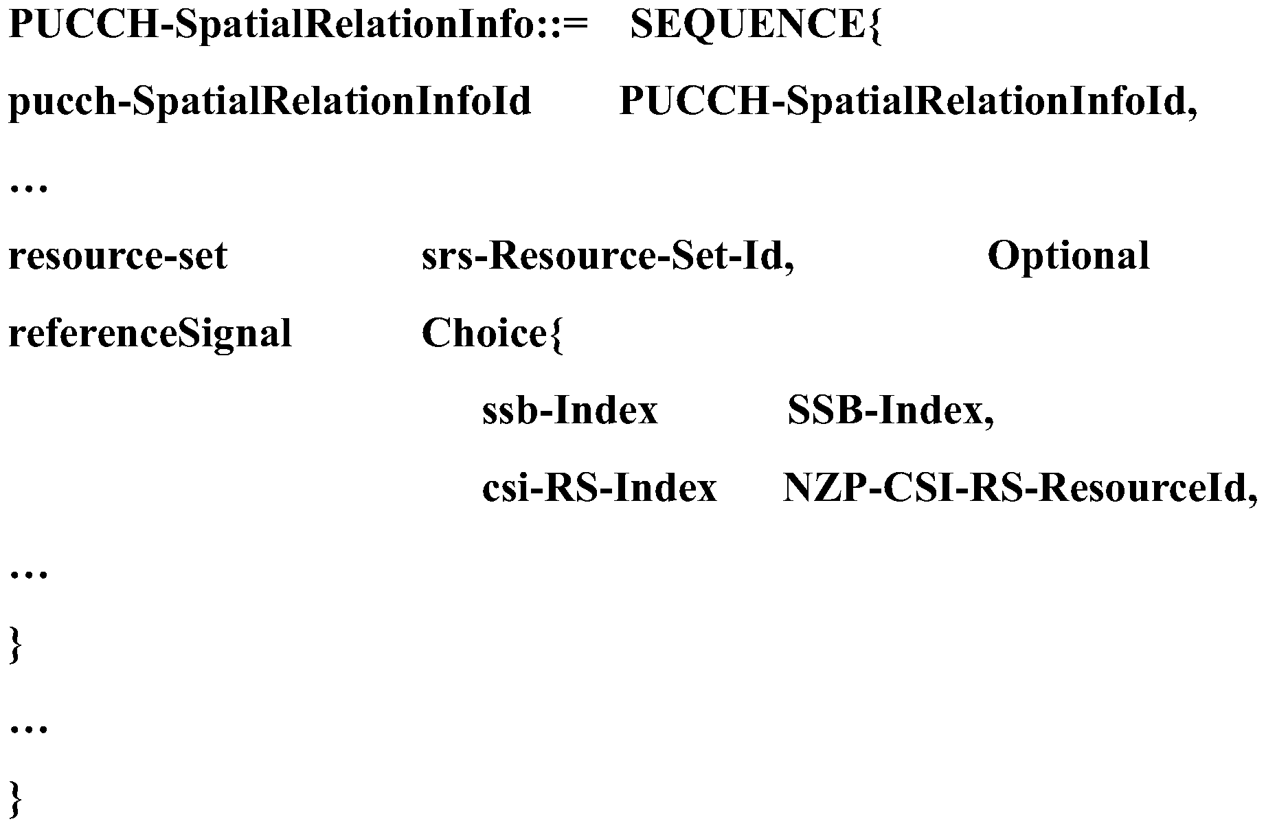
如上所述,PUCCH-SpatialRelationInfoId表示RRC参数PUCCH-SpatialRelationInfo的识别信息,即ID,SSB-Index或NZP-CSI-RS-ResourceId表示SSB或NZP-CSI-RS资源识别信息以通知用户设备选择相应的SSB或NZP-CSI-RS的接收波束作为发送PUCCH信号的发射波束。根据本公开的实施例,在上述RRC参数中添加了关于SRS资源集合的识别信息,即srs-Resource-Set-Id,从而使得网络侧设备200在向用户设备通知用于发送PUCCH信号的发射波束的信息时能够考虑天线板的信息。As mentioned above, PUCCH-SpatialRelationInfoId represents the identification information of the RRC parameter PUCCH-SpatialRelationInfo, that is, ID, SSB-Index or NZP-CSI-RS-ResourceId represents the SSB or NZP-CSI-RS resource identification information to inform the user equipment to select the corresponding SSB. Or, the receiving beam of the NZP-CSI-RS is used as a transmitting beam for transmitting a PUCCH signal. According to the embodiment of the present disclosure, identification information about the SRS resource set, that is, srs-Resource-Set-Id is added to the above-mentioned RRC parameters, so that the network-side device 200 notifies the user equipment of a transmission beam for transmitting a PUCCH signal. The information of the antenna board can be considered.
针对上行参考信号(SRS)For Uplink Reference Signal (SRS)
与上行数据信号类似,当上行信号是SRS时,根据本公开的实施例,生成单元220生成的配置信息可以包括SRS资源集合指示信息和SRS资源指示信息。SRS资源集合指示信息可以指示用于发送上行信号的发射波 束所在的SRS资源集合。SRS资源指示信息可以指示SRS资源集合中的用于发送上行信号的发射波束所占用的资源。Similar to the uplink data signal, when the uplink signal is SRS, according to an embodiment of the present disclosure, the configuration information generated by the generating unit 220 may include SRS resource set indication information and SRS resource indication information. The SRS resource set indication information may indicate an SRS resource set where a transmission beam used to send an uplink signal is located. The SRS resource indication information may indicate resources occupied by a transmission beam used to send an uplink signal in the SRS resource set.
根据本公开的实施例,可以通过对RRC参数进行修改,以使得网络侧设备200能够向用户设备通知用于发送SRS的发射波束。具体地,可以对RRC参数中的SRS SpatialRelationInfo进行修改,如下所示:According to the embodiment of the present disclosure, the RRC parameter may be modified so that the network-side device 200 can notify the user equipment of a transmission beam used to send the SRS. Specifically, the SRS SpatialRelationInfo in the RRC parameters can be modified as follows:
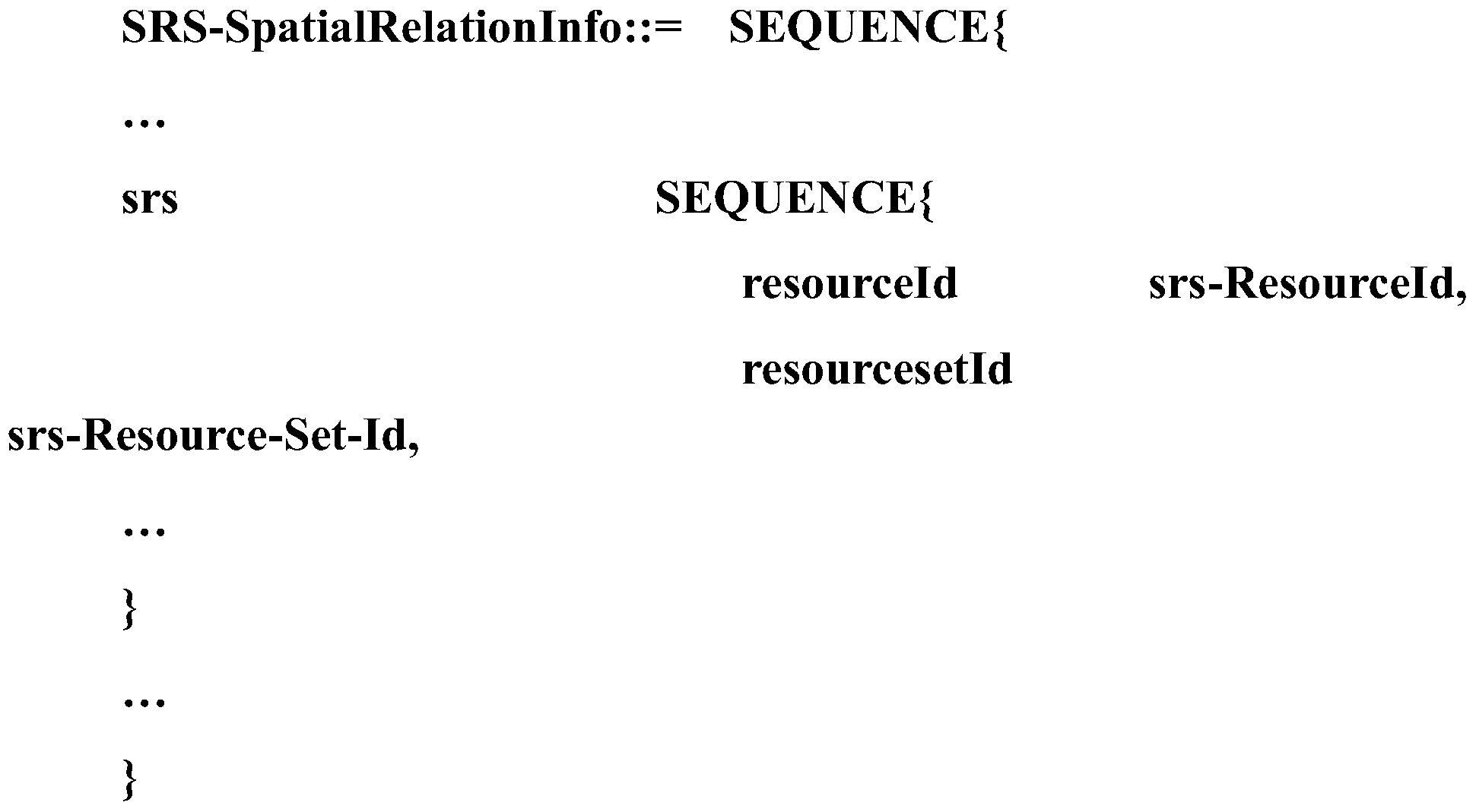
如上所述,srs-ResourceId表示用于发送SRS的发射波束的SRS资源识别信息。根据本公开的实施例,在上述RRC参数中添加了关于SRS资源集合的识别信息,即srs-Resource-Set-Id,从而使得网络侧设备200在向用户设备通知用于发送SRS的发射波束的信息时能够考虑天线板的信息。As described above, the srs-ResourceId indicates the SRS resource identification information of the transmission beam used to transmit the SRS. According to the embodiment of the present disclosure, identification information about the SRS resource set, that is, srs-Resource-Set-Id is added to the above-mentioned RRC parameters, so that the network-side device 200 notifies the user equipment of the transmission beam used to send the SRS. Information can be considered in the antenna board.
根据本公开的实施例,对于上行信号是SRS的情况,配置单元210配置的用于发送上行信号的发射波束同样可以包括一个或多个发射波束。在用于发送SRS的发射波束包括多个发射波束的情况下,在上面示例中的参数srs-ResourceId和srs-Resource-Set-Id均可以扩展到多个。According to the embodiment of the present disclosure, for a case where the uplink signal is an SRS, the transmission beam configured to send the uplink signal by the configuration unit 210 may also include one or more transmission beams. In the case where the transmission beam used to send the SRS includes multiple transmission beams, the parameters srs-ResourceId and srs-Resource-Set-Id in the above example can be extended to multiple.
与上行数据信号类似,当上行信号是SRS时,根据本公开的另一实施例,生成单元220生成的配置信息可以包括下行参考信号(即CSI-RS资源指示或SSB资源指示)以及SRS资源集合指示信息。SRS资源集合指示信息可以指示用于接收下行信号的接收波束的天线面板。CSI-RS资源指示信息可以指示用于接收下行参考信号CSI-RS的波束用做发送SRS的发射波束。SSB资源指示可以指示用于接收下行参考信号SSB的波束 用做发送SRS的发射波束。Similar to the uplink data signal, when the uplink signal is an SRS, according to another embodiment of the present disclosure, the configuration information generated by the generating unit 220 may include a downlink reference signal (that is, a CSI-RS resource indication or an SSB resource indication) and an SRS resource set. Instructions. The SRS resource set indication information may indicate an antenna panel for receiving a receiving beam of a downlink signal. The CSI-RS resource indication information may indicate that a beam for receiving a downlink reference signal CSI-RS is used as a transmission beam for transmitting an SRS. The SSB resource indication may indicate that a beam for receiving a downlink reference signal SSB is used as a transmission beam for transmitting SRS.
根据本公开的实施例,可以通过对RRC参数进行修改,以使得网络侧设备200能够向用户设备通知用于发送SRS的发射波束。具体地,可以对RRC参数中的SRS SpatialRelationInfo进行修改,如下所示:According to the embodiment of the present disclosure, the RRC parameter may be modified so that the network-side device 200 can notify the user equipment of a transmission beam used to send the SRS. Specifically, the SRS SpatialRelationInfo in the RRC parameters can be modified as follows:
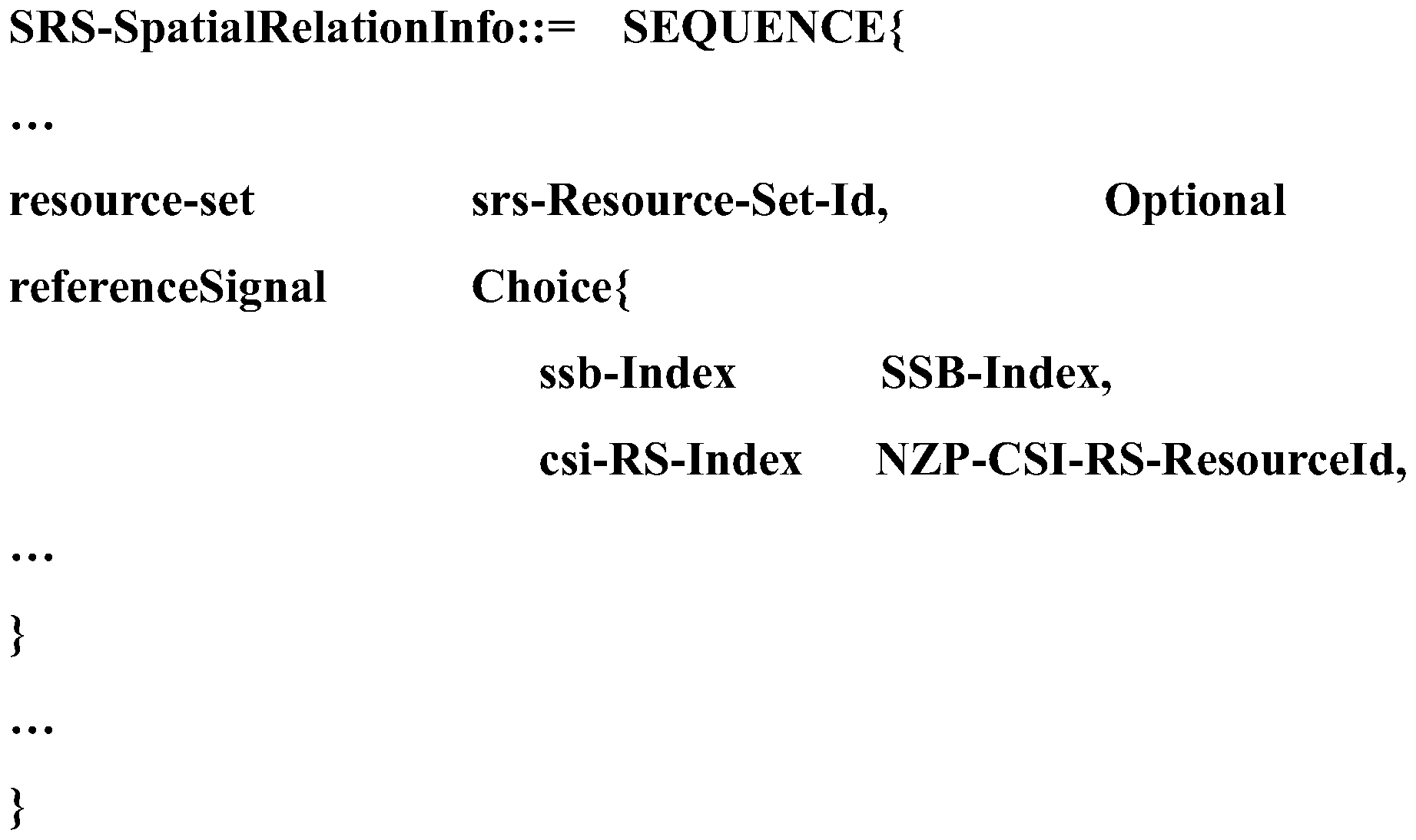
如上所述,SSB-Index或NZP-CSI-RS-ResourceId表示SSB或NZP-CSI-RS资源识别信息以通知用户设备选择相应的SSB或NZP-CSI-RS的接收波束作为发送SRS信号的发射波束。根据本公开的实施例,在上述RRC参数中添加了关于SRS资源集合的识别信息,即srs-Resource-Set-Id,从而使得网络侧设备200在向用户设备通知用于发送SRS信号的发射波束的信息时能够考虑天线板的信息。As described above, the SSB-Index or NZP-CSI-RS-ResourceId indicates the SSB or NZP-CSI-RS resource identification information to notify the user equipment to select the corresponding SSB or NZP-CSI-RS receiving beam as the transmitting beam for transmitting the SRS signal. . According to the embodiment of the present disclosure, identification information about the SRS resource set, that is, srs-Resource-Set-Id, is added to the above-mentioned RRC parameters, so that the network-side device 200 notifies the user equipment of the transmission beam used to send the SRS signal. The information of the antenna board can be considered.
如上所述,根据本公开的实施例,无论用户设备即将发送的上行信号是数据信号、控制信号还是参考信号,都可以通过SRS资源集合指示信息和SRS资源指示信息的组合来表征配置单元210配置的发射波束,从而使得用户设备能够确定特定天线板上的特定发射波束来发送上行信号。此外,在用户设备即将发送的上行信号是数据信号的情况下,还可以通过RRC参数来表征配置单元210配置的发射波束,从而使得用户设备能够确定与该RRC参数相对应的发射波束,并确定特定天线板上的特定发射波束来发送上行数据信号。综上,根据本公开的实施例的网络侧设备200,生成的配置信息中携带了用户设备的天线板的信息,因此能够优化上行发射波束的确定过程。As described above, according to the embodiments of the present disclosure, regardless of whether an uplink signal to be sent by a user equipment is a data signal, a control signal, or a reference signal, the configuration of the configuration unit 210 may be characterized by a combination of SRS resource set indication information and SRS resource indication information. , So that the user equipment can determine a specific transmit beam on a specific antenna board to send an uplink signal. In addition, when the uplink signal to be sent by the user equipment is a data signal, the transmission beam configured by the configuration unit 210 may also be characterized by an RRC parameter, so that the user equipment can determine a transmission beam corresponding to the RRC parameter and determine A specific transmit beam on a specific antenna board sends an uplink data signal. In summary, according to the network-side device 200 according to the embodiment of the present disclosure, the configuration information generated carries the information of the antenna plate of the user equipment, so the determination process of the uplink transmission beam can be optimized.
<3.用户设备的配置示例><3. Configuration example of user equipment>
图9是示出根据本公开的实施例的无线通信系统中的用户设备900的结构的框图。如图9所示,用户设备900可以包括通信单元910和确定单元920。FIG. 9 is a block diagram showing a structure of a user equipment 900 in a wireless communication system according to an embodiment of the present disclosure. As shown in FIG. 9, the user equipment 900 may include a communication unit 910 and a determination unit 920.
这里,用户设备900的各个单元都可以包括在处理电路中。需要说明的是,用户设备900既可以包括一个处理电路,也可以包括多个处理电路。进一步,处理电路可以包括各种分立的功能单元以执行各种不同的功能和/或操作。需要说明的是,这些功能单元可以是物理实体或逻辑实体,并且不同称谓的单元可能由同一个物理实体实现。Here, each unit of the user equipment 900 may be included in a processing circuit. It should be noted that the user equipment 900 may include one processing circuit or multiple processing circuits. Further, the processing circuit may include various discrete functional units to perform various different functions and / or operations. It should be noted that these functional units may be physical entities or logical entities, and units with different names may be implemented by the same physical entity.
根据本公开的实施例,通信单元910可以接收指示用于发送上行信号的发射波束的配置信息。According to an embodiment of the present disclosure, the communication unit 910 may receive configuration information indicating a transmission beam for transmitting an uplink signal.
根据本公开的实施例,确定单元920可以根据通信单元910接收到的配置信息从用户设备的多个天线板上的多个发射波束中确定用于发送上行信号的发射波束。According to an embodiment of the present disclosure, the determining unit 920 may determine a transmission beam for transmitting an uplink signal from multiple transmission beams on multiple antenna boards of the user equipment according to the configuration information received by the communication unit 910.
根据本公开的实施例,用户设备的多个天线板与多个SRS资源集合一一对应,并且每个天线板上的波束与SRS资源集合中的SRS资源一一对应。According to the embodiment of the present disclosure, the multiple antenna boards of the user equipment correspond to the multiple SRS resource sets one-to-one, and the beams on each antenna board correspond to the SRS resources in the SRS resource set one-to-one.
根据本公开的实施例,通信单元910可以通过高层信令接收配置信息。该高层信令包括但不限于RRC信令。进一步,确定单元920可以根据配置信息确定用于发送上行非数据信号的发射波束。According to an embodiment of the present disclosure, the communication unit 910 may receive configuration information through high-level signaling. The high-level signaling includes, but is not limited to, RRC signaling. Further, the determining unit 920 may determine a transmission beam for transmitting an uplink non-data signal according to the configuration information.
这里,上行非数据信号可以包括上行参考信号和上行控制信号。上行控制信号包括PUCCH信号,上行参考信号包括SRS。Here, the uplink non-data signal may include an uplink reference signal and an uplink control signal. The uplink control signal includes a PUCCH signal, and the uplink reference signal includes an SRS.
根据本公开的实施例,通信单元910可以通过低层信令接收配置信息。该低层信令包括但不限于DCI信令。进一步,确定单元920可以根据配置信息确定用于发送上行数据信号,例如PUSCH信号的发射波束。According to an embodiment of the present disclosure, the communication unit 910 may receive configuration information through low-level signaling. The low-level signaling includes, but is not limited to, DCI signaling. Further, the determining unit 920 may determine a transmission beam used to send an uplink data signal, for example, a PUSCH signal, according to the configuration information.
根据本公开的实施例,确定单元920确定出的用于发送上行信号的发射波束可以包括一个或多个发射波束。According to an embodiment of the present disclosure, the transmission beam determined by the determining unit 920 for sending an uplink signal may include one or more transmission beams.
下面将针对数据信号、控制信号和参考信号分别详细说明根据本公开的实施例的确定单元920示例。Examples of the determination unit 920 according to the embodiment of the present disclosure will be described in detail below for the data signal, the control signal, and the reference signal, respectively.
针对上行数据信号(PUSCH信号)For uplink data signals (PUSCH signals)
根据本公开的实施例,确定单元920可以根据配置信息确定SRS资 源集合指示信息和SRS资源指示信息。According to an embodiment of the present disclosure, the determining unit 920 may determine the SRS resource set indication information and the SRS resource indication information according to the configuration information.
进一步,根据本公开的实施例,确定单元920可以根据SRS资源集合指示信息确定用于发送上行信号的发射波束所在的SRS资源集合,并且根据SRS资源指示信息从其所在的SRS资源集合中确定用于发送上行信号的发射波束。Further, according to the embodiment of the present disclosure, the determining unit 920 may determine an SRS resource set where a transmission beam used to send an uplink signal is located according to the SRS resource set indication information, and determine an SRS resource set from the SRS resource set in which it is located according to the SRS resource indication information. A transmit beam for transmitting uplink signals.
例如,确定单元920可以根据SRS资源集合指示信息确定用于发送上行信号的发射波束所在的SRS资源集合的识别信息。例如,确定单元920可以根据SRSI确定用于发送上行信号的SRS资源集合的编号。进一步,确定单元920可以根据SRS资源指示信息确定用于发送上行信号的发射波束在其所在的SRS资源集合内的识别信息。例如,根据SRI确定用于发送上行信号的SRS资源在其所在的SRS资源集合中的编号。For example, the determining unit 920 may determine the identification information of the SRS resource set where the transmission beam used to send the uplink signal is located according to the SRS resource set instruction information. For example, the determining unit 920 may determine the number of the SRS resource set used to send the uplink signal according to the SRSI. Further, the determining unit 920 may determine, according to the SRS resource indication information, identification information of a transmission beam used to send an uplink signal within an SRS resource set in which the transmission beam is located. For example, the number of the SRS resource used to send the uplink signal in the SRS resource set in which it is located is determined according to the SRI.
根据本公开的实施例,确定单元920可以根据配置信息确定多组指示信息,每组指示信息都包括一个SRS资源集合指示信息和一个SRS资源指示信息。According to an embodiment of the present disclosure, the determining unit 920 may determine multiple sets of indication information according to the configuration information, and each set of indication information includes one SRS resource set indication information and one SRS resource indication information.
如上所述,确定单元920可以根据配置信息确定一组或多组指示信息,每组指示信息包括SRS资源集合指示信息和SRS资源指示信息。由此,确定单元920可以确定一个或多个用于发送上行数据信号的发射波束。As described above, the determining unit 920 may determine one or more sets of indication information according to the configuration information, and each set of indication information includes SRS resource set indication information and SRS resource indication information. Thus, the determining unit 920 may determine one or more transmission beams for transmitting an uplink data signal.
根据本公开的实施例,确定单元920可以根据配置信息中包括的RRC参数确定与该RRC参数对应的发射波束作为用于发送上行信号的发射波束。例如,RRC参数可以是前文中所述的SpatialRelationInfo参数。According to an embodiment of the present disclosure, the determining unit 920 may determine a transmission beam corresponding to the RRC parameter as a transmission beam for transmitting an uplink signal according to an RRC parameter included in the configuration information. For example, the RRC parameter may be the SpatialRelationInfo parameter described above.
根据本公开的实施例,与RRC参数对应的发射波束表示与RRC参数对应的上行信号所使用的发射波束。这里,与RRC参数对应的上行信号包括以下中的至少一种:与RRC参数对应的上行数据信号、与RRC参数对应的上行控制信号和与RRC参数对应的上行参考信号。According to an embodiment of the present disclosure, the transmission beam corresponding to the RRC parameter represents a transmission beam used by an uplink signal corresponding to the RRC parameter. Here, the uplink signal corresponding to the RRC parameter includes at least one of the following: an uplink data signal corresponding to the RRC parameter, an uplink control signal corresponding to the RRC parameter, and an uplink reference signal corresponding to the RRC parameter.
根据本公开的实施例,确定单元920可以根据配置信息中包括的一个或多个RRC参数确定一个或多个用于发送上行数据信号的发射波束。According to an embodiment of the present disclosure, the determining unit 920 may determine one or more transmission beams for transmitting an uplink data signal according to one or more RRC parameters included in the configuration information.
根据本公开的实施例,如图9所示,用户设备900还可以包括扫描单元930,用于执行上行波束扫描过程,以用于网络侧设备识别用户设备900的多个天线板上的多个发射波束。According to an embodiment of the present disclosure, as shown in FIG. 9, the user equipment 900 may further include a scanning unit 930 configured to perform an uplink beam scanning process for the network-side device to identify multiple ones on multiple antenna boards of the user equipment 900. Transmit beam.
如上所述,在确定单元920确定了一个或多个用于发送上行数据信 号的发射波束后,用户设备900可以利用确定的发射波束发送上行数据信号,即PUSCH信号。As described above, after the determining unit 920 determines one or more transmission beams for transmitting an uplink data signal, the user equipment 900 may use the determined transmission beams to send an uplink data signal, that is, a PUSCH signal.
针对上行控制信号(PUCCH信号)For uplink control signal (PUCCH signal)
与PUSCH信号类似,根据本公开的实施例,确定单元920可以根据配置信息确定SRS资源集合指示信息和SRS资源指示信息。进一步,确定单元920可以根据SRS资源集合指示信息确定用于发送上行控制信号的发射波束所在的SRS资源集合,并且根据SRS资源指示信息从其所在的SRS资源集合中确定用于发送PUCCH信号的发射波束。Similar to the PUSCH signal, according to an embodiment of the present disclosure, the determining unit 920 may determine the SRS resource set indication information and the SRS resource indication information according to the configuration information. Further, the determining unit 920 may determine the SRS resource set where the transmission beam used to send the uplink control signal is located according to the SRS resource set indication information, and determine the transmission used to send the PUCCH signal from the SRS resource set where it is located according to the SRS resource indication information Beam.
根据本公开的实施例,确定单元920可以根据配置信息确定多组指示信息,每组指示信息都包括一个SRS资源集合指示信息和一个SRS资源指示信息。According to an embodiment of the present disclosure, the determining unit 920 may determine multiple sets of indication information according to the configuration information, and each set of indication information includes one SRS resource set indication information and one SRS resource indication information.
在确定单元920确定了一个或多个用于发送PUCCH信号的发射波束后,用户设备900可以利用确定的发射波束发送PUCCH信号。After the determining unit 920 determines one or more transmission beams for transmitting a PUCCH signal, the user equipment 900 may use the determined transmission beams to transmit the PUCCH signal.
针对上行参考信号(SRS)For Uplink Reference Signal (SRS)
与PUSCH信号类似,根据本公开的实施例,确定单元920可以根据配置信息确定SRS资源集合指示信息和SRS资源指示信息。进一步,确定单元920可以根据SRS资源集合指示信息确定用于发送上行参考信号的发射波束所在的SRS资源集合,并且根据SRS资源指示信息从其所在的SRS资源集合中确定用于发送SRS的发射波束。Similar to the PUSCH signal, according to an embodiment of the present disclosure, the determining unit 920 may determine the SRS resource set indication information and the SRS resource indication information according to the configuration information. Further, the determining unit 920 may determine the SRS resource set where the transmission beam used to send the uplink reference signal is located according to the SRS resource set indication information, and determine the transmission beam used to send the SRS from the SRS resource set where it is located according to the SRS resource indication information .
根据本公开的实施例,确定单元920可以根据配置信息确定多组指示信息,每组指示信息都包括一个SRS资源集合指示信息和一个SRS资源指示信息。According to an embodiment of the present disclosure, the determining unit 920 may determine multiple sets of indication information according to the configuration information, and each set of indication information includes one SRS resource set indication information and one SRS resource indication information.
在确定单元920确定了一个或多个用于发送SRS的发射波束后,用户设备900可以利用确定的发射波束发送SRS。After the determining unit 920 determines one or more transmission beams for transmitting the SRS, the user equipment 900 may transmit the SRS by using the determined transmission beams.
如上所述,根据本公开的实施例,无论用户设备即将发送的上行信号是数据信号、控制信号还是参考信号,都可以通过SRS资源集合指示信息和SRS资源指示信息的组合来确定特定天线板上的特定发射波束。此外,在用户设备即将发送的上行信号是数据信号的情况下,还可以通过RRC参数来确定与该RRC参数相对应的发射波束,并确定特定天线板上的特定发射波束。综上,根据本公开的实施例的用户设备900,接收到的配置信息中携带了用户设备900的天线板的信息,因此能够优化上行发射波束的确定过程。As described above, according to the embodiments of the present disclosure, whether an uplink signal to be sent by a user equipment is a data signal, a control signal, or a reference signal, a specific antenna board may be determined through a combination of SRS resource set indication information and SRS resource indication information. Specific transmit beam. In addition, when the uplink signal to be sent by the user equipment is a data signal, a transmission beam corresponding to the RRC parameter may also be determined through an RRC parameter, and a specific transmission beam on a specific antenna board may be determined. In summary, according to the user equipment 900 according to the embodiment of the present disclosure, the received configuration information carries information about the antenna plate of the user equipment 900, so the determination process of the uplink transmit beam can be optimized.
根据本公开的实施例的网络侧设备200可以为用户设备900提供服务,因此在前文中描述的关于网络侧设备200的全部实施例都适用于此。The network-side device 200 according to the embodiment of the present disclosure may provide services to the user equipment 900, so all the embodiments described above regarding the network-side device 200 are applicable to this.
<4.方法实施例><4. Method Embodiment>
接下来将详细描述根据本公开实施例的由无线通信系统中的网络侧设备200执行的无线通信方法。Next, a wireless communication method performed by the network-side device 200 in a wireless communication system according to an embodiment of the present disclosure will be described in detail.
图10是示出根据本公开的实施例的由无线通信系统中的网络侧设备200执行的无线通信方法的流程图。FIG. 10 is a flowchart illustrating a wireless communication method performed by a network-side device 200 in a wireless communication system according to an embodiment of the present disclosure.
如图10所示,在步骤S1010中,从用户设备的多个天线板上的多个发射波束中为用户设备配置用于发送上行信号的发射波束。As shown in FIG. 10, in step S1010, the user equipment is configured from a plurality of transmit beams on multiple antenna boards of the user equipment to transmit a transmit beam for transmitting an uplink signal.
接下来,在步骤S1020中,生成配置信息,配置信息指示用于发送上行信号的发射波束。Next, in step S1020, configuration information is generated, and the configuration information indicates a transmission beam for transmitting an uplink signal.
优选地,用户设备的多个天线板与多个SRS资源集合一一对应,并且每个天线板上的一个或多个发射波束中与SRS资源集合中的SRS资源一一对应。Preferably, the multiple antenna boards of the user equipment correspond to the multiple SRS resource sets one-to-one, and one or more transmission beams on each antenna board correspond to the SRS resources in the SRS resource set one-to-one.
优选地,配置信息包括SRS资源集合指示信息和SRS资源指示信息。Preferably, the configuration information includes SRS resource set indication information and SRS resource indication information.
优选地,SRS资源集合指示信息指示用于发送上行信号的发射波束所在的SRS资源集合,并且SRS资源指示信息指示SRS资源集合中的用于发送上行信号的发射波束所占用的资源。Preferably, the SRS resource set indication information indicates the SRS resource set where the transmission beam used to send the uplink signal is located, and the SRS resource indication information indicates the resources occupied by the transmission beam used to send the uplink signal in the SRS resource set.
优选地,配置信息包括RRC参数,以指示用户设备使用与RRC参数对应的发射波束来发送上行信号。Preferably, the configuration information includes RRC parameters to instruct the user equipment to send an uplink signal using a transmission beam corresponding to the RRC parameters.
优选地,与RRC参数对应的发射波束表示与RRC参数对应的上行信号所使用的发射波束。Preferably, the transmission beam corresponding to the RRC parameter represents a transmission beam used by an uplink signal corresponding to the RRC parameter.
优选地,与RRC参数对应的上行信号包括以下中的至少一种:与RRC参数对应的上行数据信号、与RRC参数对应的上行控制信号和与RRC参数对应的上行参考信号。Preferably, the uplink signal corresponding to the RRC parameter includes at least one of the following: an uplink data signal corresponding to the RRC parameter, an uplink control signal corresponding to the RRC parameter, and an uplink reference signal corresponding to the RRC parameter.
优选地,上行信号包括非数据信号,并且无线通信方法还包括:通过高层信令向用户设备发送配置信息。Preferably, the uplink signal includes a non-data signal, and the wireless communication method further includes: sending configuration information to the user equipment through high-level signaling.
优选地,非数据信号包括上行参考信号和上行控制信号。Preferably, the non-data signal includes an uplink reference signal and an uplink control signal.
优选地,上行信号包括数据信号,并且无线通信方法还包括:通过低层信令向用户设备发送配置信息。Preferably, the uplink signal includes a data signal, and the wireless communication method further includes: sending configuration information to the user equipment through low-level signaling.
优选地,无线通信方法还包括:根据用户设备的波束扫描过程识别用户设备的多个天线板上的多个发射波束。Preferably, the wireless communication method further includes: identifying multiple transmit beams on multiple antenna boards of the user equipment according to a beam scanning process of the user equipment.
优选地,用于发送上行信号的发射波束包括一个或多个发射波束。Preferably, the transmission beam used to send the uplink signal includes one or more transmission beams.
根据本公开的实施例,执行上述方法的主体可以是根据本公开的实施例的网络侧设备200,因此前文中关于网络侧设备200的全部实施例均适用于此。According to the embodiment of the present disclosure, the main body that executes the above method may be the network-side device 200 according to the embodiment of the present disclosure, so all the embodiments of the network-side device 200 described above are applicable to this.
接下来将详细描述根据本公开实施例的由无线通信系统中的用户设备900执行的无线通信方法。Next, a wireless communication method performed by a user equipment 900 in a wireless communication system according to an embodiment of the present disclosure will be described in detail.
图11是示出根据本公开的实施例的由无线通信系统中的用户设备900执行的无线通信方法的流程图。FIG. 11 is a flowchart illustrating a wireless communication method performed by a user equipment 900 in a wireless communication system according to an embodiment of the present disclosure.
如图11所示,在步骤S1110中,接收指示用于发送上行信号的发射波束的配置信息。As shown in FIG. 11, in step S1110, configuration information indicating a transmission beam for transmitting an uplink signal is received.
接下来,在步骤S1120中,根据配置信息从用户设备的多个天线板上的多个发射波束中确定用于发送上行信号的发射波束。Next, in step S1120, a transmission beam for transmitting an uplink signal is determined from multiple transmission beams on multiple antenna boards of the user equipment according to the configuration information.
优选地,用户设备的多个天线板与多个SRS资源集合一一对应,并且每个天线板上的一个或多个发射波束中与SRS资源集合中的SRS资源一一对应。Preferably, the multiple antenna boards of the user equipment correspond to the multiple SRS resource sets one-to-one, and one or more transmission beams on each antenna board correspond to the SRS resources in the SRS resource set one-to-one.
优选地,无线通信方法还包括:根据配置信息确定SRS资源集合指示信息和SRS资源指示信息。Preferably, the wireless communication method further includes: determining the SRS resource set indication information and the SRS resource indication information according to the configuration information.
优选地,无线通信方法还包括:根据SRS资源集合指示信息确定用于发送上行信号的发射波束所在的SRS资源集合;以及根据SRS资源指示信息从SRS资源集合中确定用于发送上行信号的发射波束。Preferably, the wireless communication method further includes: determining, according to the SRS resource set indication information, the SRS resource set where the transmission beam used to send the uplink signal is located; and determining the transmission beam used to send the uplink signal from the SRS resource set according to the SRS resource set information. .
优选地,无线通信方法还包括:根据配置信息中包括的RRC参数确定与RRC参数对应的发射波束作为用于发送上行信号的发射波束。Preferably, the wireless communication method further includes: determining, according to the RRC parameters included in the configuration information, a transmission beam corresponding to the RRC parameter as a transmission beam for transmitting an uplink signal.
优选地,与RRC参数对应的发射波束表示与RRC参数对应的上行信号所使用的发射波束。Preferably, the transmission beam corresponding to the RRC parameter represents a transmission beam used by an uplink signal corresponding to the RRC parameter.
优选地,与RRC参数对应的上行信号包括以下中的至少一种:与RRC参数对应的上行数据信号、与RRC参数对应的上行控制信号和与RRC参数对应的上行参考信号。Preferably, the uplink signal corresponding to the RRC parameter includes at least one of the following: an uplink data signal corresponding to the RRC parameter, an uplink control signal corresponding to the RRC parameter, and an uplink reference signal corresponding to the RRC parameter.
优选地,接收配置信息包括:通过高层信令接收所述配置信息,并 且无线通信方法还包括:根据配置信息确定用于发送上行非数据信号的发射波束。Preferably, receiving the configuration information includes: receiving the configuration information through high-level signaling, and the wireless communication method further includes: determining a transmission beam for sending an uplink non-data signal according to the configuration information.
优选地,上行非数据信号包括上行参考信号和上行控制信号。Preferably, the uplink non-data signal includes an uplink reference signal and an uplink control signal.
优选地,接收配置信息包括:通过低层信令接收配置信息,并且无线通信方法还包括:根据配置信息确定用于发送上行数据信号的发射波束。Preferably, receiving the configuration information includes receiving the configuration information through low-level signaling, and the wireless communication method further includes determining a transmission beam for sending an uplink data signal according to the configuration information.
优选地,无线通信方法还包括:执行上行波束扫描过程,以用于网络侧设备识别用户设备的多个天线板上的多个发射波束。Preferably, the wireless communication method further includes: performing an uplink beam scanning process for the network-side device to identify multiple transmit beams on multiple antenna boards of the user equipment.
优选地,确定用于发送上行信号的发射波束包括:确定用于发送上行信号的一个或多个发射波束。Preferably, determining the transmission beam used to send the uplink signal includes: determining one or more transmission beams used to send the uplink signal.
根据本公开的实施例,执行上述方法的主体可以是根据本公开的实施例的用户设备900,因此前文中关于用户设备900的全部实施例均适用于此。According to the embodiment of the present disclosure, the subject performing the above method may be the user equipment 900 according to the embodiment of the present disclosure, so all the embodiments of the user equipment 900 in the foregoing are applicable here.
<5.应用示例><5. Application example>
本公开内容的技术能够应用于各种产品。The technology of the present disclosure can be applied to various products.
例如,网络侧设备可以被实现为任何类型的TRP。该TRP可以具备发送和接收功能,例如可以从用户设备和基站设备接收信息,也可以向用户设备和基站设备发送信息。在典型的示例中,TRP可以为用户设备提供服务,并且受基站设备的控制。进一步,TRP可以具备与如下所述的基站设备类似的结构,也可以仅具备基站设备中与发送和接收信息相关的结构。For example, the network-side device can be implemented as any type of TRP. The TRP may have sending and receiving functions. For example, the TRP may receive information from user equipment and base station equipment, and may also send information to user equipment and base station equipment. In a typical example, TRP can provide services to user equipment and is controlled by base station equipment. Further, the TRP may have a structure similar to the base station device described below, or may only have a structure related to sending and receiving information in the base station device.
网络侧设备也可以被实现为任何类型的基站设备,诸如宏eNB和小eNB,还可以被实现为任何类型的gNB。小eNB可以为覆盖比宏小区小的小区的eNB,诸如微微eNB、微eNB和家庭(毫微微)eNB。代替地,基站可以被实现为任何其他类型的基站,诸如NodeB和基站收发台(BTS)。基站可以包括:被配置为控制无线通信的主体(也称为基站设备);以及设置在与主体不同的地方的一个或多个远程无线头端(RRH)。Network-side equipment can also be implemented as any type of base station equipment, such as macro eNBs and small eNBs, and can also be implemented as any type of gNB. A small eNB may be an eNB covering a cell smaller than a macro cell, such as a pico eNB, a pico eNB, and a home (femto) eNB. Alternatively, the base station may be implemented as any other type of base station, such as a NodeB and a base transceiver station (BTS). The base station may include: a main body (also referred to as a base station device) configured to control wireless communication; and one or more remote wireless headends (RRH) provided at a place different from the main body.
用户设备可以被实现为移动终端(诸如智能电话、平板个人计算机(PC)、笔记本式PC、便携式游戏终端、便携式/加密狗型移动路由器和数字摄像装置)或者车载终端(诸如汽车导航设备)。用户设备还可以被实现为执行机器对机器(M2M)通信的终端(也称为机器类型通信(MTC) 终端)。此外,用户设备可以为安装在上述用户设备中的每个用户设备上的无线通信模块(诸如包括单个晶片的集成电路模块)。The user equipment may be implemented as a mobile terminal such as a smartphone, a tablet personal computer (PC), a notebook PC, a portable game terminal, a portable / dongle-type mobile router, and a digital camera device, or a vehicle-mounted terminal such as a car navigation device. User equipment can also be implemented as a terminal (also known as a machine type communication (MTC) terminal) that performs machine-to-machine (M2M) communication. In addition, the user equipment may be a wireless communication module (such as an integrated circuit module including a single chip) mounted on each of the user equipments described above.
<关于基站的应用示例><Application example about base station>
(第一应用示例)(First application example)
图12是示出可以应用本公开内容的技术的gNB的示意性配置的第一示例的框图。gNB 1200包括一个或多个天线1210以及基站设备1220。基站设备1220和每个天线1210可以经由RF线缆彼此连接。FIG. 12 is a block diagram showing a first example of a schematic configuration of a gNB to which the technology of the present disclosure can be applied. The
天线1210中的每一个均包括单个或多个天线元件(诸如包括在多输入多输出(MIMO)天线中的多个天线元件),并且用于基站设备1220发送和接收无线信号。如图12所示,gNB 1200可以包括多个天线1210。例如,多个天线1210可以与gNB 1200使用的多个频带兼容。虽然图12示出其中gNB 1200包括多个天线1210的示例,但是gNB 1200也可以包括单个天线1210。Each of the
基站设备1220包括控制器1221、存储器1222、网络接口1223以及无线通信接口1225。The
控制器1221可以为例如CPU或DSP,并且操作基站设备1220的较高层的各种功能。例如,控制器1221根据由无线通信接口1225处理的信号中的数据来生成数据分组,并经由网络接口1223来传递所生成的分组。控制器1221可以对来自多个基带处理器的数据进行捆绑以生成捆绑分组,并传递所生成的捆绑分组。控制器1221可以具有执行如下控制的逻辑功能:该控制诸如为无线资源控制、无线承载控制、移动性管理、接纳控制和调度。该控制可以结合附近的gNB或核心网节点来执行。存储器1222包括RAM和ROM,并且存储由控制器1221执行的程序和各种类型的控制数据(诸如终端列表、传输功率数据以及调度数据)。The
网络接口1223为用于将基站设备1220连接至核心网1224的通信接口。控制器1221可以经由网络接口1223而与核心网节点或另外的gNB进行通信。在此情况下,gNB 1200与核心网节点或其他gNB可以通过逻辑接口(诸如S1接口和X2接口)而彼此连接。网络接口1223还可以为有线通信接口或用于无线回程线路的无线通信接口。如果网络接口1223为无线通信接口,则与由无线通信接口1225使用的频带相比,网络接口1223可以使用较高频带用于无线通信。The
无线通信接口1225支持任何蜂窝通信方案(诸如长期演进(LTE) 和LTE-先进),并且经由天线1210来提供到位于gNB 1200的小区中的终端的无线连接。无线通信接口1225通常可以包括例如基带(BB)处理器1226和RF电路1227。BB处理器1226可以执行例如编码/解码、调制/解调以及复用/解复用,并且执行层(例如L1、介质访问控制(MAC)、无线链路控制(RLC)和分组数据汇聚协议(PDCP))的各种类型的信号处理。代替控制器1221,BB处理器1226可以具有上述逻辑功能的一部分或全部。BB处理器1226可以为存储通信控制程序的存储器,或者为包括被配置为执行程序的处理器和相关电路的模块。更新程序可以使BB处理器1226的功能改变。该模块可以为插入到基站设备1220的槽中的卡或刀片。可替代地,该模块也可以为安装在卡或刀片上的芯片。同时,RF电路1227可以包括例如混频器、滤波器和放大器,并且经由天线1210来传送和接收无线信号。The
如图12所示,无线通信接口1225可以包括多个BB处理器1226。例如,多个BB处理器1226可以与gNB 1200使用的多个频带兼容。如图12所示,无线通信接口1225可以包括多个RF电路1227。例如,多个RF电路1227可以与多个天线元件兼容。虽然图12示出其中无线通信接口1225包括多个BB处理器1226和多个RF电路1227的示例,但是无线通信接口1225也可以包括单个BB处理器1226或单个RF电路1227。As shown in FIG. 12, the
(第二应用示例)(Second application example)
图13是示出可以应用本公开内容的技术的gNB的示意性配置的第二示例的框图。gNB 1330包括一个或多个天线1340、基站设备1350和RRH 1360。RRH 1360和每个天线1340可以经由RF线缆而彼此连接。基站设备1350和RRH 1360可以经由诸如光纤线缆的高速线路而彼此连接。FIG. 13 is a block diagram showing a second example of a schematic configuration of a gNB to which the technology of the present disclosure can be applied. The
天线1340中的每一个均包括单个或多个天线元件(诸如包括在MIMO天线中的多个天线元件)并且用于RRH 1360发送和接收无线信号。如图13所示,gNB 1330可以包括多个天线1340。例如,多个天线1340可以与gNB 1330使用的多个频带兼容。虽然图13示出其中gNB 1330包括多个天线1340的示例,但是gNB 1330也可以包括单个天线1340。Each of the
基站设备1350包括控制器1351、存储器1352、网络接口1353、无线通信接口1355以及连接接口1357。控制器1351、存储器1352和网络接口1353与参照图12描述的控制器1221、存储器1222和网络接口1223相同。The
无线通信接口1355支持任何蜂窝通信方案(诸如LTE和LTE-先进),并且经由RRH 1360和天线1340来提供到位于与RRH 1360对应的扇区中的终端的无线通信。无线通信接口1355通常可以包括例如BB处理器1356。除了BB处理器1356经由连接接口1357连接到RRH 1360的RF电路1364之外,BB处理器1356与参照图12描述的BB处理器1226相同。如图13所示,无线通信接口1355可以包括多个BB处理器1356。例如,多个BB处理器1356可以与gNB 1330使用的多个频带兼容。虽然图13示出其中无线通信接口1355包括多个BB处理器1356的示例,但是无线通信接口1355也可以包括单个BB处理器1356。The
连接接口1357为用于将基站设备1350(无线通信接口1355)连接至RRH 1360的接口。连接接口1357还可以为用于将基站设备1350(无线通信接口1355)连接至RRH 1360的上述高速线路中的通信的通信模块。The
RRH 1360包括连接接口1361和无线通信接口1363。The
连接接口1361为用于将RRH 1360(无线通信接口1363)连接至基站设备1350的接口。连接接口1361还可以为用于上述高速线路中的通信的通信模块。The
无线通信接口1363经由天线1340来传送和接收无线信号。无线通信接口1363通常可以包括例如RF电路1364。RF电路1364可以包括例如混频器、滤波器和放大器,并且经由天线1340来传送和接收无线信号。如图13所示,无线通信接口1363可以包括多个RF电路1364。例如,多个RF电路1364可以支持多个天线元件。虽然图13示出其中无线通信接口1363包括多个RF电路1364的示例,但是无线通信接口1363也可以包括单个RF电路1364。The
在图12和图13所示的gNB 1200和gNB 1330中,通过使用图2所描述的配置单元210和生成单元220可以由控制器1221和/或控制器1351实现。功能的至少一部分也可以由控制器1221和控制器1351实现。例如,控制器1221和/或控制器1351可以通过执行相应的存储器中存储的指令而执行配置用于发送上行信号的发射波束以及生成配置信息的功能。In the
<关于终端设备的应用示例><Application example about terminal equipment>
(第一应用示例)(First application example)
图14是示出可以应用本公开内容的技术的智能电话1400的示意性配置的示例的框图。智能电话1400包括处理器1401、存储器1402、存储装置1403、外部连接接口1404、摄像装置1406、传感器1407、麦克风1408、输入装置1409、显示装置1410、扬声器1411、无线通信接口1412、一个或多个天线开关1415、一个或多个天线1416、总线1417、电池1418以及辅助控制器1419。FIG. 14 is a block diagram showing an example of a schematic configuration of a
处理器1401可以为例如CPU或片上系统(SoC),并且控制智能电话1400的应用层和另外层的功能。存储器1402包括RAM和ROM,并且存储数据和由处理器1401执行的程序。存储装置1403可以包括存储介质,诸如半导体存储器和硬盘。外部连接接口1404为用于将外部装置(诸如存储卡和通用串行总线(USB)装置)连接至智能电话1400的接口。The
摄像装置1406包括图像传感器(诸如电荷耦合器件(CCD)和互补金属氧化物半导体(CMOS)),并且生成捕获图像。传感器1407可以包括一组传感器,诸如测量传感器、陀螺仪传感器、地磁传感器和加速度传感器。麦克风1408将输入到智能电话1400的声音转换为音频信号。输入装置1409包括例如被配置为检测显示装置1410的屏幕上的触摸的触摸传感器、小键盘、键盘、按钮或开关,并且接收从用户输入的操作或信息。显示装置1410包括屏幕(诸如液晶显示器(LCD)和有机发光二极管(OLED)显示器),并且显示智能电话1400的输出图像。扬声器1411将从智能电话1400输出的音频信号转换为声音。The
无线通信接口1412支持任何蜂窝通信方案(诸如LTE和LTE-先进),并且执行无线通信。无线通信接口1412通常可以包括例如BB处理器1413和RF电路1414。BB处理器1413可以执行例如编码/解码、调制/解调以及复用/解复用,并且执行用于无线通信的各种类型的信号处理。同时,RF电路1414可以包括例如混频器、滤波器和放大器,并且经由天线1416来传送和接收无线信号。无线通信接口1412可以为其上集成有BB处理器1413和RF电路1414的一个芯片模块。如图14所示,无线通信接口1412可以包括多个BB处理器1413和多个RF电路1414。虽然图14示出其中无线通信接口1412包括多个BB处理器1413和多个RF电路1414的示例,但是无线通信接口1412也可以包括单个BB处理器1413或单个RF电路1414。The
此外,除了蜂窝通信方案之外,无线通信接口1412可以支持另外类型的无线通信方案,诸如短距离无线通信方案、近场通信方案和无线局域 网(LAN)方案。在此情况下,无线通信接口1412可以包括针对每种无线通信方案的BB处理器1413和RF电路1414。In addition, in addition to the cellular communication scheme, the
天线开关1415中的每一个在包括在无线通信接口1412中的多个电路(例如用于不同的无线通信方案的电路)之间切换天线1416的连接目的地。Each of the
天线1416中的每一个均包括单个或多个天线元件(诸如包括在MIMO天线中的多个天线元件),并且用于无线通信接口1412传送和接收无线信号。如图14所示,智能电话1400可以包括多个天线1416。虽然图14示出其中智能电话1400包括多个天线1416的示例,但是智能电话1400也可以包括单个天线1416。Each of the
此外,智能电话1400可以包括针对每种无线通信方案的天线1416。在此情况下,天线开关1415可以从智能电话1400的配置中省略。In addition, the
总线1417将处理器1401、存储器1402、存储装置1403、外部连接接口1404、摄像装置1406、传感器1407、麦克风1408、输入装置1409、显示装置1410、扬声器1411、无线通信接口1412以及辅助控制器1419彼此连接。电池1418经由馈线向图14所示的智能电话1400的各个块提供电力,馈线在图中被部分地示为虚线。辅助控制器1419例如在睡眠模式下操作智能电话1400的最小必需功能。The
在图14所示的智能电话1400中,通过使用图9所描述的确定单元920和扫描单元930可以由由处理器1401或辅助控制器1419实现。功能的至少一部分也可以由处理器1401或辅助控制器1419实现。例如,处理器1401或辅助控制器1419可以通过执行存储器1402或存储装置1403中存储的指令而执行确定用于发送上行信号的发射波束以及执行上行波束扫描的功能。In the
(第二应用示例)(Second application example)
图15是示出可以应用本公开内容的技术的汽车导航设备1520的示意性配置的示例的框图。汽车导航设备1520包括处理器1521、存储器1522、全球定位系统(GPS)模块1524、传感器1525、数据接口1526、内容播放器1527、存储介质接口1528、输入装置1529、显示装置1530、扬声器1531、无线通信接口1533、一个或多个天线开关1536、一个或多个天线1537以及电池1538。FIG. 15 is a block diagram showing an example of a schematic configuration of a
处理器1521可以为例如CPU或SoC,并且控制汽车导航设备1520 的导航功能和另外的功能。存储器1522包括RAM和ROM,并且存储数据和由处理器1521执行的程序。The
GPS模块1524使用从GPS卫星接收的GPS信号来测量汽车导航设备1520的位置(诸如纬度、经度和高度)。传感器1525可以包括一组传感器,诸如陀螺仪传感器、地磁传感器和空气压力传感器。数据接口1526经由未示出的终端而连接到例如车载网络1541,并且获取由车辆生成的数据(诸如车速数据)。The
内容播放器1527再现存储在存储介质(诸如CD和DVD)中的内容,该存储介质被插入到存储介质接口1528中。输入装置1529包括例如被配置为检测显示装置1530的屏幕上的触摸的触摸传感器、按钮或开关,并且接收从用户输入的操作或信息。显示装置1530包括诸如LCD或OLED显示器的屏幕,并且显示导航功能的图像或再现的内容。扬声器1531输出导航功能的声音或再现的内容。The
无线通信接口1533支持任何蜂窝通信方案(诸如LTE和LTE-先进),并且执行无线通信。无线通信接口1533通常可以包括例如BB处理器1534和RF电路1535。BB处理器1534可以执行例如编码/解码、调制/解调以及复用/解复用,并且执行用于无线通信的各种类型的信号处理。同时,RF电路1535可以包括例如混频器、滤波器和放大器,并且经由天线1537来传送和接收无线信号。无线通信接口1533还可以为其上集成有BB处理器1534和RF电路1535的一个芯片模块。如图15所示,无线通信接口1533可以包括多个BB处理器1534和多个RF电路1535。虽然图15示出其中无线通信接口1533包括多个BB处理器1534和多个RF电路1535的示例,但是无线通信接口1533也可以包括单个BB处理器1534或单个RF电路1535。The
此外,除了蜂窝通信方案之外,无线通信接口1533可以支持另外类型的无线通信方案,诸如短距离无线通信方案、近场通信方案和无线LAN方案。在此情况下,针对每种无线通信方案,无线通信接口1533可以包括BB处理器1534和RF电路1535。In addition, in addition to the cellular communication scheme, the
天线开关1536中的每一个在包括在无线通信接口1533中的多个电路(诸如用于不同的无线通信方案的电路)之间切换天线1537的连接目的地。Each of the
天线1537中的每一个均包括单个或多个天线元件(诸如包括在 MIMO天线中的多个天线元件),并且用于无线通信接口1533传送和接收无线信号。如图15所示,汽车导航设备1520可以包括多个天线1537。虽然图15示出其中汽车导航设备1520包括多个天线1537的示例,但是汽车导航设备1520也可以包括单个天线1537。Each of the
此外,汽车导航设备1520可以包括针对每种无线通信方案的天线1537。在此情况下,天线开关1536可以从汽车导航设备1520的配置中省略。In addition, the
电池1538经由馈线向图15所示的汽车导航设备1520的各个块提供电力,馈线在图中被部分地示为虚线。电池1538累积从车辆提供的电力。The
在图15示出的汽车导航设备1520中,通过使用图9所描述的确定单元920和扫描单元930可以由处理器1521实现。功能的至少一部分也可以由处理器1521实现。例如,处理器1521可以通过执行存储器1522中存储的指令而执行确定用于发送上行信号的发射波束以及执行上行波束扫描的功能。In the
本公开内容的技术也可以被实现为包括汽车导航设备1520、车载网络1541以及车辆模块1542中的一个或多个块的车载系统(或车辆)1540。车辆模块1542生成车辆数据(诸如车速、发动机速度和故障信息),并且将所生成的数据输出至车载网络1541。The technology of the present disclosure may also be implemented as an in-vehicle system (or vehicle) 1540 including one or more of a
以上参照附图描述了本公开的优选实施例,但是本公开当然不限于以上示例。本领域技术人员可在所附权利要求的范围内得到各种变更和修改,并且应理解这些变更和修改自然将落入本公开的技术范围内。The preferred embodiments of the present disclosure have been described above with reference to the accompanying drawings, but the present disclosure is of course not limited to the above examples. A person skilled in the art may find various alternations and modifications within the scope of the appended claims, and it should be understood that they will naturally come under the technical scope of the present disclosure.
例如,附图所示的功能框图中以虚线框示出的单元均表示该功能单元在相应装置中是可选的,并且各个可选的功能单元可以以适当的方式进行组合以实现所需功能。For example, the units shown by dashed boxes in the functional block diagram shown in the drawings all indicate that the functional unit is optional in the corresponding device, and each optional functional unit can be combined in an appropriate manner to achieve the required function .
例如,在以上实施例中包括在一个单元中的多个功能可以由分开的装置来实现。替选地,在以上实施例中由多个单元实现的多个功能可分别由分开的装置来实现。另外,以上功能之一可由多个单元来实现。无需说,这样的配置包括在本公开的技术范围内。For example, a plurality of functions included in one unit in the above embodiments may be implemented by separate devices. Alternatively, multiple functions implemented by multiple units in the above embodiments may be implemented by separate devices, respectively. In addition, one of the above functions may be implemented by multiple units. Needless to say, such a configuration is included in the technical scope of the present disclosure.
在该说明书中,流程图中所描述的步骤不仅包括以所述顺序按时间序列执行的处理,而且包括并行地或单独地而不是必须按时间序列执行的处理。此外,甚至在按时间序列处理的步骤中,无需说,也可以适当地改变该顺序。In this specification, the steps described in the flowchart include not only processes performed in time series in the described order, but also processes performed in parallel or individually instead of having to be performed in time series. Further, even in the steps processed in a time series, needless to say, the order can be appropriately changed.
以上虽然结合附图详细描述了本公开的实施例,但是应当明白,上面所描述的实施方式只是用于说明本公开,而并不构成对本公开的限制。对于本领域的技术人员来说,可以对上述实施方式作出各种修改和变更而没有背离本公开的实质和范围。因此,本公开的范围仅由所附的权利要求及其等效含义来限定。Although the embodiments of the present disclosure have been described in detail above with reference to the accompanying drawings, it should be understood that the embodiments described above are only used to illustrate the present disclosure and do not constitute a limitation on the present disclosure. It will be apparent to those skilled in the art that various modifications and variations can be made to the above-described embodiments without departing from the spirit and scope of the disclosure. Accordingly, the scope of the present disclosure is limited only by the following claims and their equivalents.
Claims (49)
Priority Applications (3)
| Application Number | Priority Date | Filing Date | Title |
|---|---|---|---|
| CN201880094850.9A CN112314027A (en) | 2018-09-26 | 2018-11-05 | Network side equipment, user equipment, wireless communication method and storage medium |
| US17/258,172 US20210288711A1 (en) | 2018-09-26 | 2018-11-05 | Network device, user equipment, wireless communication method and storage medium |
| US18/075,441 US12143188B2 (en) | 2018-09-26 | 2022-12-06 | Network device, user equipment, wireless communication method and storage medium |
Applications Claiming Priority (2)
| Application Number | Priority Date | Filing Date | Title |
|---|---|---|---|
| CN201811123667.5 | 2018-09-26 | ||
| CN201811123667.5A CN110958042A (en) | 2018-09-26 | 2018-09-26 | Network side device, user equipment, wireless communication method and storage medium |
Related Child Applications (2)
| Application Number | Title | Priority Date | Filing Date |
|---|---|---|---|
| US17/258,172 A-371-Of-International US20210288711A1 (en) | 2018-09-26 | 2018-11-05 | Network device, user equipment, wireless communication method and storage medium |
| US18/075,441 Continuation US12143188B2 (en) | 2018-09-26 | 2022-12-06 | Network device, user equipment, wireless communication method and storage medium |
Publications (1)
| Publication Number | Publication Date |
|---|---|
| WO2020062444A1 true WO2020062444A1 (en) | 2020-04-02 |
Family
ID=69952804
Family Applications (1)
| Application Number | Title | Priority Date | Filing Date |
|---|---|---|---|
| PCT/CN2018/113905 Ceased WO2020062444A1 (en) | 2018-09-26 | 2018-11-05 | Network device, user equipment, wireless communication method and storage medium |
Country Status (3)
| Country | Link |
|---|---|
| US (2) | US20210288711A1 (en) |
| CN (2) | CN110958042A (en) |
| WO (1) | WO2020062444A1 (en) |
Cited By (2)
| Publication number | Priority date | Publication date | Assignee | Title |
|---|---|---|---|---|
| EP4106397A4 (en) * | 2020-02-12 | 2023-06-07 | Datang Mobile Communications Equipment Co., Ltd. | Uplink transmission characteristic confirming method, information reporting method, and related device |
| EP4149146A4 (en) * | 2020-05-08 | 2023-08-30 | Beijing Xiaomi Mobile Software Co., Ltd. | UPLINK TRANSMISSION METHOD, DEVICE AND DEVICE, AND STORAGE MEDIUM |
Families Citing this family (10)
| Publication number | Priority date | Publication date | Assignee | Title |
|---|---|---|---|---|
| US12069678B2 (en) * | 2019-02-07 | 2024-08-20 | Lg Electronics Inc. | Method for performing uplink transmission in wireless communication systems, and device for same |
| CN111614450B (en) * | 2019-04-26 | 2021-10-01 | 维沃移动通信有限公司 | Indication method of terminal antenna panel information, network side device and terminal |
| US11576052B2 (en) * | 2019-05-03 | 2023-02-07 | Qualcomm Incorporated | Panel specific uplink transmission |
| EP4593302A3 (en) * | 2020-02-13 | 2025-08-06 | Telefonaktiebolaget LM Ericsson (publ) | Pusch reliability enhancements with multiple trps |
| WO2021162496A1 (en) * | 2020-02-13 | 2021-08-19 | 엘지전자 주식회사 | Method and device for transmitting/receiving sounding reference signals in wireless communication system |
| WO2021168599A1 (en) * | 2020-02-24 | 2021-09-02 | Qualcomm Incorporated | Reference signal configurations for uplink beam selection |
| EP3968532A1 (en) * | 2020-09-14 | 2022-03-16 | Nokia Technologies Oy | User equipment beam correspondence |
| US11728850B2 (en) * | 2020-10-12 | 2023-08-15 | Qualcomm Incorporated | Techniques for indicating a panel identifier in reporting received beams |
| CN113015257A (en) * | 2021-02-08 | 2021-06-22 | 浙江香农通信科技有限公司 | Scheduling request processing method and system for 5G NR |
| WO2024026633A1 (en) * | 2022-08-01 | 2024-02-08 | 北京小米移动软件有限公司 | Method and device for transmitting capability information, and readable storage medium |
Citations (2)
| Publication number | Priority date | Publication date | Assignee | Title |
|---|---|---|---|---|
| WO2014196962A1 (en) * | 2013-06-04 | 2014-12-11 | Nokia Solutions And Networks Oy | Methods and apparatus for antenna elevation design |
| CN108112075A (en) * | 2017-05-05 | 2018-06-01 | 中兴通讯股份有限公司 | The definite method of uplink transmission parameter and the sending method of configuration information |
Family Cites Families (3)
| Publication number | Priority date | Publication date | Assignee | Title |
|---|---|---|---|---|
| CN106686620B (en) * | 2015-11-06 | 2021-06-22 | 索尼公司 | Wireless communication device and wireless communication method |
| WO2018128365A1 (en) * | 2017-01-05 | 2018-07-12 | 엘지전자(주) | Method for transmitting physical uplink control channel in wireless communication system, and device therefor |
| US10560851B2 (en) * | 2017-01-13 | 2020-02-11 | Samsung Electronics Co., Ltd. | Method and apparatus for uplink beam management in next generation wireless systems |
-
2018
- 2018-09-26 CN CN201811123667.5A patent/CN110958042A/en active Pending
- 2018-11-05 US US17/258,172 patent/US20210288711A1/en not_active Abandoned
- 2018-11-05 WO PCT/CN2018/113905 patent/WO2020062444A1/en not_active Ceased
- 2018-11-05 CN CN201880094850.9A patent/CN112314027A/en active Pending
-
2022
- 2022-12-06 US US18/075,441 patent/US12143188B2/en active Active
Patent Citations (2)
| Publication number | Priority date | Publication date | Assignee | Title |
|---|---|---|---|---|
| WO2014196962A1 (en) * | 2013-06-04 | 2014-12-11 | Nokia Solutions And Networks Oy | Methods and apparatus for antenna elevation design |
| CN108112075A (en) * | 2017-05-05 | 2018-06-01 | 中兴通讯股份有限公司 | The definite method of uplink transmission parameter and the sending method of configuration information |
Non-Patent Citations (2)
| Title |
|---|
| HUAWEI ET AL.: "Discussion on panel-based UL beam selection", 3GPP TSG RAN WG1 MEETING #94 R1-1809122, 24 August 2018 (2018-08-24), XP051516491 * |
| VIVO: "Discussion on beam measurement, beam reporting and beam indication", 3GPP TSG RAN WG1 NR AD HOC #3 R1-1715619, 21 September 2017 (2017-09-21), XP051339086 * |
Cited By (3)
| Publication number | Priority date | Publication date | Assignee | Title |
|---|---|---|---|---|
| EP4106397A4 (en) * | 2020-02-12 | 2023-06-07 | Datang Mobile Communications Equipment Co., Ltd. | Uplink transmission characteristic confirming method, information reporting method, and related device |
| US12381612B2 (en) | 2020-02-12 | 2025-08-05 | Datang Mobile Communications Equipment Co., Ltd | Uplink transmission characteristic confirmation method, information report method and device |
| EP4149146A4 (en) * | 2020-05-08 | 2023-08-30 | Beijing Xiaomi Mobile Software Co., Ltd. | UPLINK TRANSMISSION METHOD, DEVICE AND DEVICE, AND STORAGE MEDIUM |
Also Published As
| Publication number | Publication date |
|---|---|
| US12143188B2 (en) | 2024-11-12 |
| US20230102698A1 (en) | 2023-03-30 |
| US20210288711A1 (en) | 2021-09-16 |
| CN112314027A (en) | 2021-02-02 |
| CN110958042A (en) | 2020-04-03 |
Similar Documents
| Publication | Publication Date | Title |
|---|---|---|
| US12143188B2 (en) | Network device, user equipment, wireless communication method and storage medium | |
| EP3352381B1 (en) | Electronic device in wireless communication system, and wireless communication method | |
| CN106470096B (en) | Apparatus and method for base station side and user equipment side for wireless communication | |
| CN113382449A (en) | Electronic device and method for wireless communication, computer-readable storage medium | |
| WO2021169904A1 (en) | Electronic device for wireless communication, method, and computer readable storage medium | |
| US12289761B2 (en) | Electronic device and method for wireless communication, and computer-readable storage medium | |
| US12369146B2 (en) | User equipment, electronic device, wireless communication method, and storage medium | |
| CN113453271A (en) | Electronic device and method for wireless communication, computer-readable storage medium | |
| KR20210108960A (en) | Electronic devices and methods used for wireless communication, and computer-readable storage media | |
| CN114930956A (en) | Electronic device, method, and storage medium for wireless communication system | |
| CN112514433A (en) | Communication apparatus, communication control method, and recording medium | |
| US12362804B2 (en) | Electronic device, wireless communication method, and computer readable storage medium | |
| WO2021047444A1 (en) | Electronic device, wireless communication method and computer-readable storage medium | |
| US12563541B2 (en) | Electronic device and method for wireless communication, and computer-readable storage medium | |
| US12289143B2 (en) | Electronic device, wireless communication method, and computer-readable storage medium | |
| CN116938404A (en) | User equipment, electronic device, wireless communication method, and storage medium |
Legal Events
| Date | Code | Title | Description |
|---|---|---|---|
| 121 | Ep: the epo has been informed by wipo that ep was designated in this application |
Ref document number: 18934687 Country of ref document: EP Kind code of ref document: A1 |
|
| NENP | Non-entry into the national phase |
Ref country code: DE |
|
| 122 | Ep: pct application non-entry in european phase |
Ref document number: 18934687 Country of ref document: EP Kind code of ref document: A1 |