WO2019188107A1 - Vehicle seat structure - Google Patents
Vehicle seat structure Download PDFInfo
- Publication number
- WO2019188107A1 WO2019188107A1 PCT/JP2019/009239 JP2019009239W WO2019188107A1 WO 2019188107 A1 WO2019188107 A1 WO 2019188107A1 JP 2019009239 W JP2019009239 W JP 2019009239W WO 2019188107 A1 WO2019188107 A1 WO 2019188107A1
- Authority
- WO
- WIPO (PCT)
- Prior art keywords
- thoracic vertebra
- support portion
- spring constant
- vertebra support
- occupant
- Prior art date
- Legal status (The legal status is an assumption and is not a legal conclusion. Google has not performed a legal analysis and makes no representation as to the accuracy of the status listed.)
- Ceased
Links
Images


Classifications
-
- B—PERFORMING OPERATIONS; TRANSPORTING
- B60—VEHICLES IN GENERAL
- B60N—SEATS SPECIALLY ADAPTED FOR VEHICLES; VEHICLE PASSENGER ACCOMMODATION NOT OTHERWISE PROVIDED FOR
- B60N2/00—Seats specially adapted for vehicles; Arrangement or mounting of seats in vehicles
- B60N2/70—Upholstery springs ; Upholstery
- B60N2/7094—Upholstery springs
-
- A—HUMAN NECESSITIES
- A47—FURNITURE; DOMESTIC ARTICLES OR APPLIANCES; COFFEE MILLS; SPICE MILLS; SUCTION CLEANERS IN GENERAL
- A47C—CHAIRS; SOFAS; BEDS
- A47C7/00—Parts, details, or accessories of chairs or stools
- A47C7/36—Supports for the head or the back
- A47C7/40—Supports for the head or the back for the back
-
- B—PERFORMING OPERATIONS; TRANSPORTING
- B60—VEHICLES IN GENERAL
- B60N—SEATS SPECIALLY ADAPTED FOR VEHICLES; VEHICLE PASSENGER ACCOMMODATION NOT OTHERWISE PROVIDED FOR
- B60N2/00—Seats specially adapted for vehicles; Arrangement or mounting of seats in vehicles
- B60N2/24—Seats specially adapted for vehicles; Arrangement or mounting of seats in vehicles for particular purposes or particular vehicles
- B60N2/42—Seats specially adapted for vehicles; Arrangement or mounting of seats in vehicles for particular purposes or particular vehicles the seat constructed to protect the occupant from the effect of abnormal g-forces, e.g. crash or safety seats
- B60N2/4207—Seats specially adapted for vehicles; Arrangement or mounting of seats in vehicles for particular purposes or particular vehicles the seat constructed to protect the occupant from the effect of abnormal g-forces, e.g. crash or safety seats characterised by the direction of the g-forces
- B60N2/4214—Seats specially adapted for vehicles; Arrangement or mounting of seats in vehicles for particular purposes or particular vehicles the seat constructed to protect the occupant from the effect of abnormal g-forces, e.g. crash or safety seats characterised by the direction of the g-forces longitudinal
- B60N2/4228—Seats specially adapted for vehicles; Arrangement or mounting of seats in vehicles for particular purposes or particular vehicles the seat constructed to protect the occupant from the effect of abnormal g-forces, e.g. crash or safety seats characterised by the direction of the g-forces longitudinal due to impact coming from the rear
-
- B—PERFORMING OPERATIONS; TRANSPORTING
- B60—VEHICLES IN GENERAL
- B60N—SEATS SPECIALLY ADAPTED FOR VEHICLES; VEHICLE PASSENGER ACCOMMODATION NOT OTHERWISE PROVIDED FOR
- B60N2/00—Seats specially adapted for vehicles; Arrangement or mounting of seats in vehicles
- B60N2/24—Seats specially adapted for vehicles; Arrangement or mounting of seats in vehicles for particular purposes or particular vehicles
- B60N2/42—Seats specially adapted for vehicles; Arrangement or mounting of seats in vehicles for particular purposes or particular vehicles the seat constructed to protect the occupant from the effect of abnormal g-forces, e.g. crash or safety seats
- B60N2/427—Seats or parts thereof displaced during a crash
- B60N2/42727—Seats or parts thereof displaced during a crash involving substantially rigid displacement
- B60N2/42745—Seats or parts thereof displaced during a crash involving substantially rigid displacement of the back-rest
-
- B—PERFORMING OPERATIONS; TRANSPORTING
- B60—VEHICLES IN GENERAL
- B60N—SEATS SPECIALLY ADAPTED FOR VEHICLES; VEHICLE PASSENGER ACCOMMODATION NOT OTHERWISE PROVIDED FOR
- B60N2/00—Seats specially adapted for vehicles; Arrangement or mounting of seats in vehicles
- B60N2/64—Back-rests or cushions
- B60N2/643—Back-rests or cushions shape of the back-rests
-
- B—PERFORMING OPERATIONS; TRANSPORTING
- B60—VEHICLES IN GENERAL
- B60N—SEATS SPECIALLY ADAPTED FOR VEHICLES; VEHICLE PASSENGER ACCOMMODATION NOT OTHERWISE PROVIDED FOR
- B60N2/00—Seats specially adapted for vehicles; Arrangement or mounting of seats in vehicles
- B60N2/64—Back-rests or cushions
- B60N2/66—Lumbar supports
-
- B—PERFORMING OPERATIONS; TRANSPORTING
- B60—VEHICLES IN GENERAL
- B60N—SEATS SPECIALLY ADAPTED FOR VEHICLES; VEHICLE PASSENGER ACCOMMODATION NOT OTHERWISE PROVIDED FOR
- B60N2/00—Seats specially adapted for vehicles; Arrangement or mounting of seats in vehicles
- B60N2/68—Seat frames
Definitions
- the present invention relates to a vehicle seat structure.
- a pair of left and right inclined surfaces (left inclined surface and right inclined surface) whose height increases toward the outer side in the seat width direction is provided on the cushion pan, and the passenger seated on the seat
- the reaction force acts on both the left and right seat bones from both the left slope and the right slope. Due to the reaction force acting on the left and right seat bones, the pelvis of the seated occupant swinging in the left-right direction is returned to the center side in the width direction of the seat cushion.
- the rotation center corresponding to the vicinity of the scapula of the seated occupant is set in the seat back frame, and the backrest portion that supports the back of the occupant is around the rotation center set in the seat back frame. It is suspended so that it can rotate.
- the occupant can extend the trunk lateral muscles in the direction in which the lateral force is applied, and can contract the trunk lateral muscles on the opposite side to the direction in which the lateral force is applied, resulting in improved seat holdability. .
- the head of the occupant seated on the seat is supported by the seat via the spine (spine) including the cervical vertebra, thoracic vertebra and lumbar vertebra.
- spine including the cervical vertebra, thoracic vertebra and lumbar vertebra.
- the cervical vertebra has first to seventh cervical vertebrae in order from the top, the thoracic vertebra has first to twelfth thoracic vertebrae in order from the top, and the lumbar vertebra has first to fifth lumbar vertebrae in order from the top.
- the seventh cervical vertebra to the second thoracic vertebra is referred to as the cervical thoracic vertebra transition portion, and the tenth thoracic vertebra to the second lumbar vertebra is referred to as the thoracolumbar vertebra transition portion.
- the human spine draws an S-shaped curve (vertebral curvature) in side view.
- This S-shaped curve is called a physiological lordosis.
- the cervical spine is -10 to 30 degrees (average 4.7 degrees) and the thoracic vertebra is about 5 to 45 degrees (average 24.1 degrees).
- the lumbar vertebra is formed by lordosis about 15-60 degrees (average 35.6 degrees).
- the occupant's physiological forehead can be maintained in the sitting state as in the walking state, the burden on the intervertebral disc in the skeleton is minimized, and the occupant's discomfort is reduced, making it possible to run comfortably for a long time (vehicle operation) It is considered to be. For this reason, the shape of the seat back is also made to conform to a physiological forehead.
- the occupant's spinal curvature can be maintained when the vehicle is traveling at a constant speed or when it is stopped, but the occupant may feel uncomfortable in a specific traveling state. is there.
- the thoracic vertebrae whose main purpose is to protect the thoracic organs is a special structure that indirectly touches the sternum, scapula, etc., and has a small range of motion.
- the upper thoracic vertebra (first to seventh thoracic vertebrae) surrounded by the sternum, scapula, etc. is the portion with the smallest range of motion, in other words, the most dynamically stable portion.
- the occupant's head tilts backward with the cervical-thoracic vertebra transition portion (specifically, the seventh cervical vertebra and the first thoracic vertebra) as a fulcrum, and the occupant's upper body Tilt backward with the 7th thoracic vertebra as a fulcrum. That is, the posture of the occupant when the vehicle is suddenly accelerated is a posture that is turned upside down so that the head tilts greatly backward. For this reason, when the vehicle is accelerating, the occupant may perceive a feeling of acceleration that is greater than the actual acceleration of the vehicle, and may feel uncomfortable due to the discrepancy between the own experience and the actual vehicle behavior.
- the cervical-thoracic vertebra transition portion specifically, the seventh cervical vertebra and the first thoracic vertebra
- Tilt backward with the 7th thoracic vertebra as a fulcrum
- An object of the present invention is to provide a vehicle seat structure capable of reducing a sense of discomfort of an occupant while ensuring holdability.
- the present invention provides a vehicle seat structure including a seat cushion and a seat back, wherein the seat back supports at least a portion corresponding to the lower thoracic vertebra of a seated occupant.
- a support portion and a lower thoracic vertebra support portion that is disposed in front of the upper thoracic vertebra support portion and supports a portion corresponding to the lower thoracic vertebra of the seated occupant, and when a backward inertial force acts on the seated occupant
- the lower thoracic vertebra support portion is configured to be displaced backward more than the upper thoracic vertebra support portion according to the inertial force so that the upper thoracic vertebra of the seated occupant tilts forward. is there.
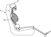
- FIG. 1 is a schematic configuration diagram of a vehicle seat according to a first embodiment of the present invention. It is explanatory drawing which shows the frame
- the vehicle seat 1 includes a headrest 2 that receives the head of a seated occupant D as its main components, and a leg mechanism that fixes the seat 1 to the passenger compartment floor. 3, a seat cushion 10 that supports a portion corresponding to the sciatic bone of the seated occupant D (a hip), and a seat back 20 that supports a portion corresponding to the spine (spine) of the seated occupant D.
- front”, “rear”, “left”, and “right” are all based on a seated occupant D seated in a normal posture (the posture shown in FIG. 1) on the vehicle seat 1. It is synonymous with “front”, “rear”, “left” and “right” of the vehicle.
- the seat cushion 10 has a front part that supports the femur from below and a rear part that is located behind the front part and supports the sciatica from below.
- the seat back 20 includes a lower part that supports the hipbone (iliac bone, pubic bone, and sciatic bone) and the lumbar vertebra from the rear, a middle part that is located above the lower part and supports the lower thoracic vertebra from the rear, and a middle part. And an upper portion for supporting the upper thoracic vertebra from the rear side.
- hipbone iliac bone, pubic bone, and sciatic bone
- the occupant D has the same dimensions as AM50 (a 50th percentile dummy doll of an American adult male).
- the human spine has, in order from the top, first to seventh cervical vertebrae, first to twelfth thoracic vertebrae, and first to fifth lumbar vertebrae.
- the uppermost first cervical vertebra is continuous with the head.
- the first cervical vertebra, the second cervical vertebra,..., The seventh cervical vertebra are abbreviated as C1, C2,... C7, and the first thoracic vertebra, the second thoracic vertebra,. , T2, ... T12, and the first lumbar vertebra, the second lumbar vertebra, ... the fifth lumbar vertebra may be abbreviated as L1, L2, ... L5.
- this abbreviation is given to each part of the spine.
- the first cervical vertebra C1, the first thoracic vertebra T1, the first lumbar vertebra L1, and the like are referred to.
- the seat back 20 of the vehicle seat 1 is approximately the cervical vertebra in a side view when the vehicle is traveling at a constant speed or stopped. It is shaped so that it is 20 degrees forward, the thoracic vertebra is approximately 20-40 degrees posterior, and the lumbar vertebra is approximately 35-60 degrees forward, that is, along the physiological lordosis of the occupant's spine.
- the upper side of the upper thoracic vertebra (the first to seventh thoracic vertebrae T1 to T7) is lower than the seventh thoracic vertebra T7.
- the clearance in the front-rear direction between the occupant D and the seat back 20 is set so as to increase toward the upper side.
- the first to seventh thoracic vertebrae T1 to T7 which are the upper thoracic vertebrae, are the parts of the spine that have the smallest range of motion.
- the upper body including the head has the seventh thoracic vertebra T7, which is the lower end of the upper thoracic vertebra. Tilt backward as a fulcrum. Further, since a backward inertial force acts on the head, the head tilts backward with the seventh cervical vertebra C7 and the first thoracic vertebra T1 as fulcrums as fulcrums.
- the inertia force is an apparent force that appears because the mass has inertia.
- the posture of the occupant D turns upside down so that the head tilts greatly backwards.
- the occupant D perceives an acceleration feeling that is greater than the actual acceleration of the vehicle, and thus may feel uncomfortable due to a mismatch between the own experience and the actual vehicle behavior.
- the backward inertial force acting on the turning outer portion located on the outer turning side of the upper body is larger than the backward inertial force acting on the turning inner portion located on the turning inner side of the upper body.
- the steering reaction force from the steering wheel acting on the arm on the outside of the turn is larger than the steering reaction force from the steering wheel acting on the arm on the inside of the turn.
- the present inventor places the upper body including the head of the seated occupant D into four regions corresponding to the head, upper thoracic vertebra, lower thoracic vertebra, and lumbar vertebra.
- a divided human body model was created, and the movement of each part due to positive acceleration was examined.
- the head weight is m1
- the upper thoracic weight is m2 (m1 ⁇ m2)
- the lower thoracic weight is m3 (m1 ⁇ m3)
- the lumbar weight is m4 (m3 ⁇ m4)
- the forward acceleration of the vehicle is ⁇ .
- the head, upper thoracic vertebra, and lower thoracic vertebra are expressed as -m1 ⁇ ⁇ , ⁇ m2 ⁇ ⁇ , ⁇ m3 ⁇ ⁇ , and ⁇ m4 ⁇ ⁇ , compared to before the occurrence (stationary state). It can be assumed that a backward inertial force acts.
- a backward movement adjustment mechanism that can individually adjust the backward movement amount with respect to the skeleton part of the occupant D in each region is applied to the seatback 20.
- the rearward movement adjusting mechanism is configured by a combination of a plurality of support portions (20a to 20e) of the seat back 20 formed so as to have different spring constants.
- the first function of the backward movement adjustment mechanism is a head tilt suppression function.
- the backward movement adjustment mechanism moves the region Xb corresponding to the lower thoracic vertebra including the eleventh thoracic vertebra T11 to the upper portion including the seventh thoracic vertebra T7. It is configured to move backward more greatly than the portion Xa corresponding to the thoracic vertebra.
- the second function of the backward movement adjustment mechanism is an upper arm support part forming function.
- the rearward movement adjustment mechanism is configured to move the rear part Xa corresponding to the upper thoracic vertebra, the rearward movement of the part Xb corresponding to the lower thoracic vertebra, and the fifth lumbar vertebra L5 when a backward inertial force is applied to the occupant D. It is comprised so that it may restrict
- the rearward movement adjusting mechanism configured as described above suppresses rearward movement of the outer scapula on the upper half of the occupant D and its peripheral part (the upper arm part on the outer side of the turn) when the vehicle is turning.
- the inertial force acting on the upper arm portion on the outside of the turn and the steering reaction force from the steering wheel acting on the upper arm portion are reliably supported, and the operability of the steering wheel is ensured.
- This is the upper arm support part forming function.
- the leg mechanism 3 is directly fixed to the vehicle floor.
- a member that substantially gives cushioning properties is not disposed between the leg mechanism 3 and the floor surface.
- the leg mechanism 3 includes a slide mechanism that supports the seat cushion 10 and the seat back 20 to be slidable in the front-rear direction with respect to the floor surface.
- This slide mechanism has a function of moving the vehicle seat 1 in the front-rear direction and a function of holding the vehicle seat 1 at a position desired by the occupant D.
- the description will proceed on the assumption that the state of the vehicle seat 1 is an initial state in which no mechanism for adjusting the posture such as lift, tilt, reclining, etc. is operated.
- the seat cushion 10 includes a metal frame member 11 that imparts structural strength to the seat cushion 10, a urethane cushion member 12, a metal elastic member 13, and each of these elements 11. And a skin material covering 13.
- the frame member 11 is a strength member having a substantially U shape in plan view, and has a pair of left and right horizontal frame portions extending in the front-rear direction, and a front frame portion that connects the front end portions of both horizontal frame portions. Yes.
- the elastic member 13 has a plurality of metal leaf springs.
- the elastic member 13 is attached so as to be elastically deformable in the vertical direction inside the seat cushion 10 by fixing both front and rear end portions thereof to the frame member 11.
- the elastic member 13 supports the buttocks of the occupant D from below while elastically deforming downward.
- the cushion member 12 is supported by the frame member 11 and the elastic member 13, and is disposed so as to cover them.
- the cushion member 12 has elastic deformation characteristics (spring characteristics) and vibration damping characteristics.
- spring characteristics spring characteristics
- vibration damping characteristics When the occupant D is seated, the cushion member 12 supports the buttocks of the occupant D in cooperation with the elastic member 13 while being compressed and deformed. The compressed and deformed cushion member 12 returns to its original shape as the occupant D leaves.
- the seat back 20 includes a metal frame member 21 for imparting structural strength to the seat back 20, a urethane cushion member 22, a metal elastic member 23, and the like. And a skin material covering each element 21, 22, 23.
- the frame member 21 is a strength member having a substantially U shape in a front view, and a pair of left and right horizontal frame portions 21a extending obliquely upward from the rear end portion of the frame member 11 for the seat cushion 10, and both horizontal frame portions 21a. And an upper frame portion 21b for connecting the upper end portions of each other. At a height position slightly below the upper frame portion 21b and a height position near the lower end portion of the frame member 21, a pair of upper and lower locked bars 21c connect the lateral frame portions 21a to the left and right. It is provided as follows.
- the elastic member 23 has a plurality of (for example, three) S-springs 23a to 23c (particularly see FIG. 9) made of metal wire extending in the vertical direction.
- the elastic member 23 is attached so as to be elastically deformable in the front-rear direction inside the seat back 20 by fixing the upper and lower ends of the S springs 23a to 23c to the upper and lower locked bars 21c of the frame member 21. Yes.
- the cushion member 22 has outer edge portions 22a that protrude forward from the center portion at both left and right side edge portions.
- the cushion member 22 is disposed on the front side of the elastic member 23 and is supported by the frame member 21 so as to partially cover the frame member 21.
- the cushion member 22 has elastic deformation characteristics (spring characteristics) and vibration damping characteristics.
- the seat back 20 is disposed in a substantially rectangular upper thoracic vertebra support portion 20 a that supports a portion Xa corresponding to the upper thoracic vertebra and a lower side than the upper thoracic vertebra support portion 20 a in a front view.
- a substantially rectangular lower thoracic vertebra support portion 20b supporting a portion Xb corresponding to the lower thoracic vertebra (T8 to T12), and disposed below the lower thoracic vertebra support portion 20b and corresponding to the lumbar vertebrae (L1 to L5)
- the seat back 20 is arranged in a slightly inclined (reclined) posture with the lower end portion as the center.
- the lower thoracic vertebra support portion 20b is positioned in front of the upper thoracic vertebra support portion 20a
- the lumbar vertebra support portion 20c is positioned in front of the lower thoracic vertebra support portion 20b.
- the support portions 20a to 20d are: It is comprised so that the conditions of following Formula (1a) may be satisfy
- a low spring constant means that it is easily deformed by an external force. That is, when a backward inertial force is applied to the occupant D, the support portion having a low spring constant is displaced (deformed) largely backward compared to the support portion having a high spring constant.
- the rearward displacement amount of the lower thoracic vertebra support portion 20b having the minimum spring constant kb is the largest.
- the amount of backward displacement of the support portion having a high spring constant (for example, the outer edge support portion 20d having the maximum spring constant kd) becomes small.
- the support portion having a high spring constant forms a backward movement inhibition region that prevents backward movement of the skeleton portion of the occupant D facing thereto.
- the upper thoracic vertebra support portion 20a has a lower end support portion 20e that supports the vicinity of the seventh thoracic vertebra T7, which is the lower end of the upper thoracic vertebra, in its inner region. More specifically, the lower end support portion 20e is formed in a region near the lower end in the sheet width direction central portion of the upper thoracic vertebra support portion 20a in order to support the seventh thoracic vertebra T7 and its peripheral portion.
- the left and right end portions of the lower end support portion 20e face the left and right scapula regions of the occupant D, respectively.
- the upper thoracic vertebra support portion 20a is configured such that the spring constant ke of the lower end support portion 20e (center lower portion) is smaller than the spring constant ka ′ of other portions. .
- the lower end support portion 20e is relatively greatly displaced rearward.
- the dent generated in the lower end support portion 20e is slightly larger than the surroundings, so that the depressed lower end support portion 20e functions to position the seventh thoracic vertebra T7 on the seat back 20, and the seat holdability is improved. improves.
- the spring constant ke of the lower end support part 20e in the upper thoracic vertebra support part 20a is substantially equal to the spring constant kc of the lumbar support part 20c (same as kc or slightly larger than kc).
- the spring constant ke of the lower end support part 20e is set so as to satisfy the condition of the following expression (3) in relation to the spring constant kb of the lower thoracic vertebra support part 20b.
- a substantially rectangular upper intermediate support portion 20f is formed between the upper thoracic vertebra support portion 20a and the lower thoracic vertebra support portion 20b.
- a substantially rectangular lower intermediate support portion 20g is formed between the lower thoracic vertebra support portion 20b and the lumbar vertebra support portion 20c.
- a pair of left and right substantially triangular intermediate support portions 20h are formed between the lower thoracic vertebra support portion 20b, the lower intermediate support portion 20g, the lumbar vertebra support portion 20c, and the left and right outer edge support portions 20d.
- the support portions 20f and 20g are configured to satisfy the condition of the following expression (4).
- kf ⁇ ka means that the spring constant kf of the upper intermediate support portion 20f is the spring constant ke of the lower end support portion 20e in the upper thoracic vertebra support portion 20a and the lower end support in the upper thoracic vertebra support portion 20a. It represents that it is smaller than any of the spring constant ka ′ of the part other than the part 20e.
- the spring constant kf of the upper intermediate support portion 20f is set to the intermediate value of the spring constants ka and kb of the upper and lower support portions (upper thoracic vertebra support portion 20a and lower thoracic vertebra support portion 20b) and
- the spring constant kg of the intermediate support portion 20g is set to an intermediate value between the spring constants kb and kc of the upper and lower support portions (lower thoracic vertebra support portion 20b and lumbar vertebra support portion 20c).
- the spring characteristic of the seat back 20 is set to a substantially symmetrical arc-shaped characteristic with respect to the eleventh thoracic vertebra T11 corresponding to the pigeon tail, holdability is ensured regardless of some physique difference, In that sense, the passenger's discomfort is reduced.
- the pair of left and right intermediate support portions 20h are formed so that the apex substantially coincides with the height of the eleventh thoracic vertebra T11.
- Each intermediate support portion 20h is formed such that its width dimension increases toward the lower side.
- the intermediate support portion 20h is configured to satisfy the condition of the following formula (5).
- the frame member 21, the cushion member 22, and the elastic member 23 can be regarded as a single spring structure having a certain spring characteristic (elastic deformation characteristic).
- the spring constants ka (ka ′, ke), kb, kc, kd, kf, kg, and kh of the support portions 20a to 20h are assumed to be that the single spring structure supports the occupant D. Calculated below.
- the single spring structure supports the weight of each part (upper thoracic vertebrae, lower thoracic vertebrae, lumbar vertebrae, etc.) of the occupant D that each of the supporters 20a to 20h is responsible for,
- the spring constants ka to kh of the support portions 20a to 20h are calculated using the structure model.
- the spring constant is assumed to be substantially constant in each support portion.
- the lower end support portion 20e of the upper thoracic vertebra support portion 20a has substantially the same spring constant at any position (the representative value is ke), and the portions other than the lower end support portion 20e in the upper thoracic vertebra support portion 20a In any of these positions, the spring constant is substantially the same (the representative value is ka ′).
- the lower thoracic vertebra support portion 20b has substantially the same spring constant at any position (the representative value is kb). The same applies to the lumbar support 20c, the outer edge support 20d, the upper intermediate support 20f, the lower intermediate support 20g, and the intermediate support 20h.
- the S springs 23a to 23c of the elastic member 23 are fixed to the left and right horizontal frame portions 21a of the frame member 21 via a plurality of connecting members 24a to 24c.
- the upper and lower ends of each S spring 23a to 23c are fixed to the upper and lower locked bars 21c of the frame member 21.
- the S springs 23a to 23c are arranged in this order from the left, and are hereinafter referred to as a left S spring 23a, an intermediate S spring 23b, and a right S spring 23c as appropriate.
- the connecting members 24a to 24c are provided at positions corresponding to the above-described support portions 20a to 20c (overlapping in front view). In order to create differences in the spring constants ka to kc of the support portions 20a to 20c, the tensions of the connecting members 24a to 24c are set to be different from each other.
- the left S spring 23a has a plurality of overhangs projecting to the left (the left outer edge support portion 20d side) at height positions corresponding to the upper thoracic vertebra support portion 20a, the lower thoracic vertebra support portion 20b, and the lumbar vertebra support portion 20c. It has parts a1 to a3.
- the intermediate S spring 23b has the same shape as the left S spring 23a. That is, the intermediate S spring 23b projects to the left (on the left outer edge support portion 20d side) at height positions corresponding to the upper thoracic vertebra support portion 20a, the lower thoracic vertebra support portion 20b, and the lumbar vertebra support portion 20c. It has parts b1 to b3.
- the right S spring 23c is formed to be bilaterally symmetric with the intermediate S spring 23b (or the left S spring 23a). That is, the right S-spring 23c extends to the right (on the right outer edge support portion 20d side) at height positions corresponding to the upper thoracic vertebra support portion 20a, the lower thoracic vertebra support portion 20b, and the lumbar vertebra support portion 20c. It has parts c1 to c3.
- the pair of left and right connecting members 24 a connect the upper portions of the left and right S springs 23 a and 23 c to both sides of the frame member 21.
- the left connecting member 24a connects the overhanging portion a1 of the left S spring 23a corresponding to the upper thoracic vertebra support portion 20a and the middle upper portion of the left lateral frame portion 21a of the frame member 21.
- the right connecting member 24a connects the overhanging portion c1 of the right S spring 23c corresponding to the upper thoracic vertebra support portion 20a and the middle upper portion of the right lateral frame portion 21a of the frame member 21.
- the pair of left and right connecting members 24b connect the center portions of the left and right S springs 23a and 23c to both side portions of the frame member 21.
- the left connecting member 24b connects the overhanging portion a2 of the left S spring 23a corresponding to the lower thoracic vertebra support portion 20b and the middle middle portion of the left lateral frame portion 21a of the frame member 21.
- the right connecting member 24b connects the overhanging portion c2 of the right S spring 23c corresponding to the lower thoracic vertebra support portion 20b and the middle middle portion of the right lateral frame portion 21a of the frame member 21.
- the pair of left and right connecting members 24 c connect the lower portions of the left and right S springs 23 a and 23 c to both sides of the frame member 21.
- the left connecting member 24c connects the overhanging portion a3 of the left S spring 23a corresponding to the lumbar vertebra support portion 20c and the middle lower portion of the left lateral frame portion 21a of the frame member 21.
- the right connecting member 24c connects the overhanging portion c3 of the right S spring 23c corresponding to the lumbar support portion 20c and the middle lower portion of the right lateral frame portion 21a of the frame member 21.
- each of the S springs 23a to 23c includes an upper intermediate support portion 20f (between the upper thoracic vertebra support portion 20a and the lower thoracic vertebra support portion 20b) and a lower intermediate support portion 20g (lower thoracic vertebra support portion 20b and They are bound to each other via a pair of upper and lower binding members 23d at height positions corresponding to the lumbar support portions 20c).
- the upper binding member 23d includes a portion between the protruding portions a1 and a2 of the left S spring 23a, a portion between the protruding portions b1 and b2 of the intermediate S spring 23b, and a portion of the right S spring 23c.
- the lower binding member 23d includes a portion between the protruding portions a2 and a3 of the left S spring 23a, a portion between the protruding portions b2 and b3 of the intermediate S spring 23b, and a portion of the right S spring 23c.
- the portions between the overhang portions c2 and c3 are bound to each other.
- the connecting members 24a to 24c have their respective connecting tensions adjusted so as to satisfy the conditions of the above formulas (1) to (4).
- the spring constants of the lower end support portion 20e, the upper intermediate support portion 20f, and the lower intermediate support portion 20g of the upper thoracic vertebra support portion 20a are not limited to the adjustment of the connection tension by the connection members 24a to 24c. 22 is adjusted by changing the spring characteristics.
- the spring constants of the lower thoracic vertebra support portion 20a, the lower end support portion 20e of the upper thoracic vertebra support portion 20a, the portion other than the lower end support portion 20e in the upper thoracic vertebra support portion 20a, and the lower thoracic vertebra support portion 20b ) Is a model set to ke, ka ′, and kb defined by (1).
- the spring constant of the upper thoracic vertebra support portion 20a (the lower end support portion 20e and other portions) is set to be equal to the spring constant kb of the lower thoracic vertebra support portion 20b in the present model M3, and the lower thoracic vertebra support portion 20b. Is set to be equal to the spring constant ke of the lower end support portion 20e in the present model M3.
- the spring constant of the lower thoracic vertebra support portion 20e of the upper thoracic vertebra support portion 20a is ke1
- the spring constant of the upper thoracic vertebra support portion 20a other than the lower end support portion 20e is ka1 '
- the spring constant of the lower thoracic vertebra support portion 20b is represented by the following formula (6).
- Ke1 ka1 ' ⁇ kb1 (6)
- the spring constants of the upper thoracic vertebra support portion 20a (the lower end support portion 20e and other portions) and the lower thoracic vertebra support portion 20b are both equivalent to twice the spring constant ke of the lower end support portion 20e in the present model M3. It is a model set to. That is, in this comparison model M2, the spring constant of the lower thoracic vertebra support portion 20a of the upper thoracic vertebra support portion 20a is ke2, the spring constant of the upper thoracic vertebra support portion 20a other than the lower end support portion 20e is ka2 ', and the lower thoracic vertebra support portion 20b Assuming that the spring constant is kb2, these magnitude relationships are expressed by the following equation (7).
- the vertebra located above the fifth lumbar vertebra L5 has a larger rearward movement amount, and therefore the head of the occupant D is tilted significantly backward (backward warping). It can be seen that the amount is excessive). In addition, it can be seen that the amount of backward movement of the seventh thoracic vertebra T7 is large, and the support points for supporting the scapula and its peripheral portion (scapula region) are not sufficiently formed.
- the rearward movement amount tends to decrease (forward inclination).
- the spring constant ke of the lower end support portion 20e formed at a position directly corresponding to the seventh thoracic vertebra T7 (overlapping in front view) is the left and right sides of the lower end support portion 20e.
- the scapula region is substantially supported at a position shifted to the left and right from the seventh thoracic vertebra T7.
- the seat back 20 of the vehicle seat 1 supports the upper thoracic vertebra supporting the portion Xa corresponding to the upper thoracic vertebra including at least the seventh thoracic vertebra T7 (lower thoracic vertebra) of the seated occupant D.
- the upper thoracic vertebra support portion 20a and the lower thoracic vertebra support portion 20b, and the lower thoracic vertebra support portion 20b which is disposed in front of the upper thoracic vertebra support portion 20a and supports the portion Xb corresponding to the lower thoracic vertebra of the seated occupant D.
- Support characteristics with 20b can be set independently.
- the lower thoracic vertebra support portion 20b can be displaced backward more greatly than the upper thoracic vertebra support portion 20a, and therefore a rotational moment that tilts the upper thoracic vertebra forward. It is possible to prevent the seat occupant D from tilting backward. That is, the forward rotational moment suppresses the rearward tilt of the head of the occupant D with the cervical-thoracic vertebra transition portion as a fulcrum during the acceleration of the vehicle, and the physiological lordage of the seated occupant D can be maintained. .
- the seat back 20 in the first embodiment further includes a lumbar support portion 20c that is disposed in front of the lower thoracic vertebra support portion 20b and supports a portion Xc corresponding to the lumbar vertebra of the seated occupant D, the upper thoracic vertebra support portion 20a.
- the support characteristics of the lumbar support 20c can be set independently. Further, when a backward inertial force is applied to the seated occupant D, the lower thoracic vertebra support portion 20b can be displaced backward more than the lumbar vertebra support portion 20c. Can be maintained.
- the spring constant kb of the lower thoracic vertebra support portion 20b is lower than the spring constant ka (ka ′, ke) of the upper thoracic vertebra support portion 20a and the spring constant kc of the lumbar vertebra support portion 20c, a simple configuration is provided.
- the lower thoracic vertebra support portion 20b can be displaced backward more than the upper thoracic vertebra support portion 20a and the lumbar vertebra support portion 20c.
- the seat back 20 in the first embodiment includes an upper intermediate support portion 20f disposed between the upper thoracic vertebra support portion 20a and the lower thoracic vertebra support portion 20b, and a lower thoracic vertebra support portion 20b and a lumbar vertebra support portion 20c.
- a lower middle support portion 20g disposed on the upper middle support portion 20f.
- the spring constant kf of the upper middle support portion 20f is an intermediate value between the spring constant ka of the upper thoracic vertebra support portion 20a and the spring constant kb of the lower thoracic vertebra support portion 20b.
- the spring constant kg of the lower intermediate support portion 20g is set to an intermediate value between the spring constant kb of the lower thoracic vertebra support portion 20b and the spring constant kc of the lumbar vertebra support portion 20c.
- the sense of discomfort of the occupant D can be reduced.
- the spring characteristic of the seat back 20 is set to an arc-shaped characteristic that is substantially symmetrical up and down with the lower thoracic vertebra support part 20b as a boundary, the occupant D is secured while maintaining the holdability regardless of some physique differences. Can reduce the sense of incongruity.
- the spring constant ke of the lower end support portion 20e of the upper thoracic vertebra support portion 20a is set to be substantially the same as the spring constant kc of the lumbar support portion 20c, the lower thoracic vertebra support portion 20b is the center. Symmetric support characteristics can be imparted to the seat back 20.
- the spring constant ke of the lower end support part 20e of the upper thoracic vertebra support part 20a is 20 N / m or more larger than the spring constant kb of the lower thoracic vertebra support part 20b, the transition to the cervical thoracic vertebra is performed when the vehicle is accelerated.
- the backward tilting of the head of the occupant D with the part as a fulcrum can be reliably suppressed.
- the spring constant ke of the lower end support portion 20e of the upper thoracic vertebra support portion 20a is set in the range of 5/4 to 7/4 of the spring constant kb of the lower thoracic vertebra support portion 20b. While the vehicle is accelerating, the rearward tilt of the head of the occupant D with the cervical thoracic vertebra transition portion as a fulcrum can be reliably suppressed.
- the main difference between the first embodiment and the second embodiment is that, in the first embodiment, the spring constants ka to kc of the support portions 20a to 20c using the S springs 23a to 23c and the connecting members 24a to 24c. In contrast, in the second embodiment, the spring constant is adjusted using the panel members 25a and 25b and the tension members 26a and 26b.
- the second embodiment will be described in detail, the same members as those in the first embodiment are denoted by the same reference numerals, and detailed description thereof will be omitted.
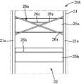
- the seat back 20 ⁇ / b> A includes a metal frame member 21 that imparts structural strength to the seat back 20 ⁇ / b> A, a urethane cushion member 22, synthetic resin panel members 25 a and 25 b, and tension. Members 26a and 26b and a skin material covering these elements are provided.
- the panel members 25a and 25b and the tension members 26a and 26b are provided so as to connect the left and right horizontal frame portions 21a of the frame member 21.
- the upper panel member 25a is disposed at a position corresponding to the upper thoracic vertebra support 20a (overlapping in front view).
- the lower panel member 25b is spaced apart from the upper panel member 25a and is disposed at a position corresponding to the lower thoracic vertebra support 20b.
- the upper tension member 26a is composed of three string-like wires 26x to 26z having predetermined elastic characteristics.
- the string-like wires 26x and 26y are fixed to the frame member 21 (lateral frame portion 21a) at positions near the four corners of the upper thoracic vertebra support portion 20a, and are arranged so as to intersect at the center of the upper thoracic vertebra support portion 20a.
- the string-like wire rods 26z are disposed so as to connect the middle portions of the string-like wire rods 26x and 26y (the portion above the crossing position between them) to the left and right above the center of the upper thoracic vertebra support portion 20a. .
- the intersection where the string-like wires 26x and 26y intersect is located immediately above the lower end support portion 20e (FIG. 7).
- the lower end support part 20e corresponding to the seventh thoracic vertebra T7 is compared with the surroundings during acceleration running. Can be slightly recessed. Further, during turning, the steering operation by the occupant D can be facilitated by supporting the lower part of the scapula of the occupant D by the lower parts of the string-like wires 26x and 26y.
- the lower tension member 26b is composed of a single string-like wire having predetermined elastic characteristics.
- the tension member 26b is disposed so as to extend left and right at a position slightly above the center of the lumbar support 20c.
- the spring constant kc of the lumbar vertebra support portion 20c becomes the largest at a position slightly above the center of the lumbar vertebra support portion 20c (that is, the position where the tension member 26b is disposed). Further, the spring constant kc decreases linearly with increasing distance from the position of the tension member 26b to the upper side or the lower side.
- the spring constant kc of the lumbar vertebra support portion 20c is set to be higher than the spring constant kb of the lower thoracic vertebra support portion 20b, and is set to be lower than the spring constant ka of the upper thoracic vertebra support portion 20a.
- the spring constants of the upper intermediate support portion 20f and the lower intermediate support portion 20g are adjusted by changing the spring characteristics of the cushion member 22 in addition to the adjustment of the panel members 25a and 25b and the tension members 26a and 26b. .
- a lower end support portion 20e is set on a part (lower center) of the upper thoracic vertebra support portion 20a, and the spring constant ke of the lower end support portion 20e is set to other portions (upper thoracic vertebra support portion 20a.
- the spring constant ke and the spring constant ka ′ may be set to the same value.
- the spring constant ke of the lower end support portion 20e of the upper thoracic vertebra support portion 20a is determined from the spring constant ka ′ of the upper thoracic vertebra support portion 20a other than the lower end support portion 20e. May be set to a large value.
- the above-described equation (1) is rewritten into the following equation (10).
- the spring constant ke is made larger than the spring constant ka ′ as described above, when a backward inertial force acts on the occupant D, the lower end support portion 20e having a relatively high spring constant ke causes the occupant D to The rearward movement of the seventh thoracic vertebra T7 is sufficiently suppressed, and the rearward movement of the scapula of the occupant is easily allowed by the portion having the relatively low spring constant ka ′ (the portion around the lower end support portion 20e). Thereby, the freedom degree of the steering operation by the passenger
- the example has been described in which the spring constant ka (ka ′, ke) of the upper thoracic vertebra support portion 20a is set to be equal to or greater than the spring constant kc of the lumbar support portion 20c (kc ⁇ ka).
- the magnitude relationship between and kc may be reversed. That is, the upper thoracic vertebra support portion 20a and the lumbar vertebra support portion 20c may be formed so that the relationship ka (ka ′, ke) ⁇ kc is established. In this way, the backward tilt of the head of the occupant D is suppressed, and the behavior of the head becomes a behavior closer to parallel movement.
- the spring constant kh of the pair of left and right intermediate support portions 20h is larger than the spring constant kc of the lumbar vertebra support portion 20c, and the spring constant kd of the pair of left and right outer edge support portions 20d
- the magnitude relationship between kc and kh may be reversed.
- the parts 20c, 20d, and 20h may be formed so that the relationship of kh ⁇ kc ⁇ kd is established. This improves the seating comfort of the seat 1 and stabilizes the posture of the occupant D when the vehicle turns.
- the example in which the spring constant of each support portion is adjusted by the panel members 25a, 25b and the tension members 26a, 26b has been described.
- the spring constant may be adjusted by using the S springs 23a to 23c in combination.
- the connecting members 24a to 24c used in the first embodiment can be additionally used as appropriate.
- the first and second functions (head tilt suppression function, upper arm support part forming function) of the rearward movement adjusting mechanism are realized by adjusting the spring constant of each support part.
- the example has been described, it is only necessary to be able to adjust the rearward movement at least for each skeleton part of the occupant D. You may control the back displacement amount of each support part according to a state. In this case, in order to move the frame, the cushion, and the elastic member integrally, it is possible to adopt the following structure.
- the frame member of the seat back has a double structure having an outer frame and an inner frame.
- the outer frame is configured to be immovable in order to protect the occupant during a side collision.
- the cushion and the elastic member are directly supported on the inner frame.
- the inner frame, the cushion, and the elastic member are divided for each support part, and are moved back and forth by the drive part for each support part.
- the vehicle seat structure includes a seat cushion and a seat back.
- the seat back includes at least an upper thoracic vertebra support that supports a portion corresponding to the lower thoracic vertebra of the seated occupant, and a lower portion that is disposed in front of the upper thoracic vertebra support and corresponds to the lower thoracic vertebra of the seated occupant And a thoracic spine support.
- the lower thoracic vertebra support part is displaced more backward than the upper thoracic vertebra support part according to the inertial force so that the upper thoracic vertebra of the seated occupant tilts forward when a backward inertial force acts on the seated occupant Configured as follows.
- the seat back includes an upper thoracic vertebra support portion that supports a portion corresponding to the lower thoracic vertebra and a lower thoracic vertebra support portion that supports a portion corresponding to the lower thoracic vertebra.
- Support characteristics of the upper thoracic vertebra support and the lower thoracic vertebra support can be set independently.
- the lower thoracic vertebra support part can be displaced backward more than the upper thoracic vertebra support part, and therefore a rotational moment that tilts the upper thoracic vertebra forward. It is possible to prevent the seated occupant from tilting backward. That is, when the vehicle is accelerated, the backward tilting of the head of the seated occupant with the cervical thoracic vertebra transition portion as a fulcrum can be suppressed and the physiological heel of the seated occupant can be maintained.
- the seat back includes a lumbar vertebra support portion that is disposed in front of the lower thoracic vertebra support portion and supports a portion corresponding to the lumbar spine of a seated occupant.
- the lower thoracic vertebra support portion is configured to be displaced backward more than the lumbar vertebra support portion when a backward inertial force acts on a seated occupant.
- the support characteristics of the lumbar support part can be set independently.
- the occupant's physiological outpost can be maintained regardless of the vehicle behavior.
- the vehicle seat structure includes a seat cushion and a seat back.
- the seat back includes at least an upper thoracic vertebra support that supports a portion corresponding to the lower thoracic vertebra of the seated occupant, and a lower portion that is disposed in front of the upper thoracic vertebra support and corresponds to the lower thoracic vertebra of the seated occupant A thoracic vertebra support portion; and a lumbar vertebra support portion that is disposed in front of the lower thoracic vertebra support portion and supports a portion corresponding to the lumbar spine of the seated occupant.
- the spring constant of the lower thoracic vertebra support is lower than the spring constant of the upper thoracic vertebra support and lumbar support.
- the lower thoracic vertebra support portion is configured by a simple configuration from the upper thoracic vertebra support portion and the lumbar vertebra support portion. Also has the effect of being greatly displaced backward.
- the vehicle seat structure is disposed between an upper intermediate support portion disposed between the upper thoracic vertebra support portion and the lower thoracic vertebra support portion, and between the lower thoracic vertebra support portion and the lumbar vertebra support portion. And a lower intermediate support portion.
- the spring constant of the upper intermediate support portion is set to an intermediate value between the spring constant of the upper thoracic vertebra support portion and the spring constant of the lower thoracic vertebra support portion.
- the spring constant of the lower intermediate support part is set to an intermediate value between the spring constant of the lower thoracic vertebra support part and the spring constant of the lumbar support part.
- the change in the spring constant can be moderated to reduce the occupant's discomfort.
- the seat back spring characteristic is set to a generally symmetric arc-shaped characteristic up and down with the lower thoracic vertebra support part as a boundary, so that the occupant feels uncomfortable while maintaining holdability regardless of some physique differences. Can be reduced.
- the upper thoracic vertebra support part has a portion in which a spring constant is set substantially the same as that of the lumbar vertebra support part.
- the upper thoracic vertebra support portion has a portion having a spring constant of 20 N / m or more larger than that of the lower thoracic vertebra support portion.
- the upper thoracic vertebra support part has a portion whose spring constant is set in a range of 5/4 to 7/4 of that of the lower thoracic vertebra support part.
- the occupant's comfort can be ensured, and the occupant's head can be reliably prevented from tilting around the cervical-thoracic vertebra transition portion during accelerating traveling of the vehicle.
Landscapes
- Engineering & Computer Science (AREA)
- Aviation & Aerospace Engineering (AREA)
- Transportation (AREA)
- Mechanical Engineering (AREA)
- Seats For Vehicles (AREA)
- Chair Legs, Seat Parts, And Backrests (AREA)
Abstract
Description
本発明は、車両用シート構造に関する。 The present invention relates to a vehicle seat structure.
従来より、車両の操作性向上等を狙いとして、シートに着座した乗員の姿勢保持機能、所謂ホールド性を改善するための様々な技術が提案されている。 Conventionally, with the aim of improving the operability of the vehicle, various techniques have been proposed to improve the so-called holdability of the occupant seated on the seat.
特許文献1の車両用シートでは、シート幅方向の外側ほど高さが高くなる左右一対の傾斜面(左部傾斜面及び右部傾斜面)がクッションパンに設けられており、シートに着座した乗員の左右の座骨に左部傾斜面及び右部傾斜面の双方から反力が作用するようになっている。この左右の座骨に作用する反力により、左右方向に揺動した着座乗員の骨盤がシートクッションの幅方向中央側に戻される。
In the vehicle seat of
また、シートバックに凭れ掛る着座乗員の胸椎及び腰椎を支持することにより、シートのホールド性を確保する技術も提案されている。 Also, a technique for securing the seat holdability by supporting the thoracic vertebrae and lumbar vertebrae of a seated occupant leaning on the seat back has been proposed.
特許文献2の車両用シートでは、着座乗員の肩甲骨付近に対応した回転中心がシートバックフレームに設定され、乗員の背部を支持するバックレスト部が、シートバックフレームに設定された回転中心回りに回動可能に吊り下げられている。
In the vehicle seat of
これにより、乗員は、横力の作用方向の体幹側方筋を伸ばすと共に、横力の作用方向と反対側の体幹側方筋を縮めることができ、結果としてシートのホールド性が向上する。 As a result, the occupant can extend the trunk lateral muscles in the direction in which the lateral force is applied, and can contract the trunk lateral muscles on the opposite side to the direction in which the lateral force is applied, resulting in improved seat holdability. .
シートに着座した乗員の頭部は、頚椎、胸椎及び腰椎を含む脊椎(背骨)を介してシートに支持される。 The head of the occupant seated on the seat is supported by the seat via the spine (spine) including the cervical vertebra, thoracic vertebra and lumbar vertebra.
頚椎は、上から順に第1~第7頚椎を有し、胸椎は、上から順に第1~第12胸椎を有し、腰椎は、上から順に第1~第5腰椎を有する。一般に、第7頚椎から第2胸椎までが頚胸椎移行部、第10胸椎から第2腰椎までが胸腰椎移行部と称される。 The cervical vertebra has first to seventh cervical vertebrae in order from the top, the thoracic vertebra has first to twelfth thoracic vertebrae in order from the top, and the lumbar vertebra has first to fifth lumbar vertebrae in order from the top. In general, the seventh cervical vertebra to the second thoracic vertebra is referred to as the cervical thoracic vertebra transition portion, and the tenth thoracic vertebra to the second lumbar vertebra is referred to as the thoracolumbar vertebra transition portion.
歩行状態や立位状態にあるときの人の脊椎(背骨)は、側面視にてS字状のカーブ(脊柱湾曲)を描く。このS字状のカーブを生理的前弯といい、頚椎が約-10~30度(平均4.7度)前弯し、胸椎が約5~45度(平均24.1度)後弯し、腰椎が約15~60度(平均35.6度)前弯することによって形成される。 When a person is walking or standing, the human spine (spine) draws an S-shaped curve (vertebral curvature) in side view. This S-shaped curve is called a physiological lordosis. The cervical spine is -10 to 30 degrees (average 4.7 degrees) and the thoracic vertebra is about 5 to 45 degrees (average 24.1 degrees). The lumbar vertebra is formed by lordosis about 15-60 degrees (average 35.6 degrees).
着座状態においても歩行状態と同様の乗員の生理的前弯を維持できれば、骨格における椎間板の負担が最小化されて乗員の違和感が軽減され、無理のない長時間の走行(車両操作)が可能になると考えられる。このため、シートバックの形状を生理的前弯に沿うような形状にすることも行われている。 If the occupant's physiological forehead can be maintained in the sitting state as in the walking state, the burden on the intervertebral disc in the skeleton is minimized, and the occupant's discomfort is reduced, making it possible to run comfortably for a long time (vehicle operation) It is considered to be. For this reason, the shape of the seat back is also made to conform to a physiological forehead.
前述の如くシートバックを生理的前弯に沿うように形成した場合、車両の定速走行時や停車時においては乗員の脊柱湾曲を維持できるものの、特定の走行状態において乗員が違和感を覚える虞がある。 As described above, when the seat back is formed so as to follow the physiological forehead, the occupant's spinal curvature can be maintained when the vehicle is traveling at a constant speed or when it is stopped, but the occupant may feel uncomfortable in a specific traveling state. is there.
屈曲、伸展、回旋動作を行う脊椎のうち、胸郭臓器保護を主目的としている胸椎は、胸骨、肩甲骨等に間接的に接する特殊構造であり、可動域が少ない部位である。特に、胸骨、肩甲骨等に囲まれた上部胸椎(第1~第7胸椎)は、最も可動域が少ない部分であり、換言すれば、最も力学的に安定した部分を構成している。 Among the vertebrae that perform flexion, extension, and rotation, the thoracic vertebrae whose main purpose is to protect the thoracic organs is a special structure that indirectly touches the sternum, scapula, etc., and has a small range of motion. In particular, the upper thoracic vertebra (first to seventh thoracic vertebrae) surrounded by the sternum, scapula, etc. is the portion with the smallest range of motion, in other words, the most dynamically stable portion.
そして、車両が急加速する場合、乗員の頭部は、頚胸椎移行部(具体的には第7頚椎及び第1胸椎)を支点として後傾し、乗員の上半身は、上部胸椎下端(具体的には第7胸椎)を支点として後傾する。すなわち、車両の急加速時における乗員の姿勢は、頭部が大きく後傾するような仰け反った姿勢となる。このため、車両の加速走行時、乗員は、車両の実際の加速度よりも大きな加速感を知覚し、自己の体感と実際の車両挙動との不一致に起因した違和感を覚えることがある。 When the vehicle suddenly accelerates, the occupant's head tilts backward with the cervical-thoracic vertebra transition portion (specifically, the seventh cervical vertebra and the first thoracic vertebra) as a fulcrum, and the occupant's upper body Tilt backward with the 7th thoracic vertebra as a fulcrum. That is, the posture of the occupant when the vehicle is suddenly accelerated is a posture that is turned upside down so that the head tilts greatly backward. For this reason, when the vehicle is accelerating, the occupant may perceive a feeling of acceleration that is greater than the actual acceleration of the vehicle, and may feel uncomfortable due to the discrepancy between the own experience and the actual vehicle behavior.
ここで、車両の加速走行時に乗員の上半身の後傾を抑制するため、加速に伴い上部胸椎下端を後方に平行移動させるべく、シートバックのばね定数を低下させることが考えられる。 Here, in order to suppress the rearward tilt of the upper body of the occupant during acceleration of the vehicle, it is conceivable that the spring constant of the seat back is lowered in order to translate the lower thoracic vertebra lower end backward in accordance with the acceleration.
しかしながら、シートバックのばね定数を低下させると、シートのホールド性が低下する上、依然として頭部による頚胸椎移行部回りの後傾が生じることから、違和感の軽減は難しい。すなわち、ホールド性を確保しつつ乗員の違和感を軽減するためには、更なる改善の余地が残されている。 However, if the spring constant of the seat back is lowered, the seat holdability is lowered, and the head is still tilted around the cervical-thoracic vertebra transition part, so it is difficult to reduce the uncomfortable feeling. That is, there is still room for further improvement in order to reduce occupant discomfort while ensuring holdability.
本発明の目的は、ホールド性を確保しつつ乗員の違和感を軽減することが可能な車両用シート構造を提供することである。 An object of the present invention is to provide a vehicle seat structure capable of reducing a sense of discomfort of an occupant while ensuring holdability.
前記目的を達成するためのものとして、本発明は、シートクッションとシートバックとを備えた車両用シート構造において、前記シートバックは、少なくとも着座乗員の上部胸椎下部に対応した部位を支持する上部胸椎支持部と、前記上部胸椎支持部よりも前側に配置され且つ着座乗員の下部胸椎に対応した部位を支持する下部胸椎支持部とを有し、着座乗員に対して後向きの慣性力が作用したときに着座乗員の上部胸椎が前方に傾動するように、前記下部胸椎支持部が前記慣性力に応じて前記上部胸椎支持部よりも大きく後方変位するように構成された、ことを特徴とするものである。 In order to achieve the above object, the present invention provides a vehicle seat structure including a seat cushion and a seat back, wherein the seat back supports at least a portion corresponding to the lower thoracic vertebra of a seated occupant. A support portion and a lower thoracic vertebra support portion that is disposed in front of the upper thoracic vertebra support portion and supports a portion corresponding to the lower thoracic vertebra of the seated occupant, and when a backward inertial force acts on the seated occupant The lower thoracic vertebra support portion is configured to be displaced backward more than the upper thoracic vertebra support portion according to the inertial force so that the upper thoracic vertebra of the seated occupant tilts forward. is there.
以下、本発明を実施するための好ましい形態を図面に基づいて説明する。以下の好ましい実施形態の説明は、本質的に例示に過ぎず、本発明、その適用物或いはその用途を制限することを意図するものではない。 Hereinafter, preferred embodiments for carrying out the present invention will be described with reference to the drawings. The following description of the preferred embodiments is merely exemplary in nature and is not intended to limit the invention, its application, or its use.
<第1実施形態>
本発明の第1実施形態について図1~図10に基づいて説明する。
<First Embodiment>
A first embodiment of the present invention will be described with reference to FIGS.
図1に示すように、第1実施形態の車両用シート1は、その主な構成要素として、着座した乗員Dの頭部を受けるヘッドレスト2と、シート1を車室床面に固定する脚機構3と、着座乗員Dの坐骨に対応した部位(臀部)を支持するシートクッション10と、着座乗員Dの脊椎(背骨)に対応した部位(背部)を支持するシートバック20とを備えている。
As shown in FIG. 1, the
なお、以下の説明において、「前」「後」「左」「右」とは、いずれも、車両用シート1に正規の姿勢(図1に示す姿勢)で着座した着座乗員Dを基準としたものであり、車両の「前」「後」「左」「右」と同義である。
In the following description, “front”, “rear”, “left”, and “right” are all based on a seated occupant D seated in a normal posture (the posture shown in FIG. 1) on the
まず、本発明の基本的な考え方について説明する。 First, the basic concept of the present invention will be described.
図2に示すように、シートクッション10は、大腿骨を下方から支持する前側部分と、前側部分よりも後側に位置し且つ坐骨を下方から支持する後側部分とを有している。
As shown in FIG. 2, the
シートバック20は、寛骨(腸骨、恥骨、坐骨)及び腰椎を後方から支持する下側部分と、下側部分よりも上側に位置し且つ下部胸椎を後方から支持する中段部分と、中段部分よりも上側に位置し且つ上部胸椎を後方から支持する上側部分とを有している。
The
なお、本実施形態では、説明の便宜上、乗員DがAM50(米国成人男性の50パーセンタイルのダミー人形)と同じ寸法を有するものとする。 In this embodiment, for convenience of explanation, it is assumed that the occupant D has the same dimensions as AM50 (a 50th percentile dummy doll of an American adult male).
人間の脊椎は、上から順に、第1~第7頚椎と、第1~第12胸椎と、第1~第5腰椎とを有する。最も上側に位置する第1頚椎は頭部に連なっている。ここで、医学の分野では、第1頚椎、第2頚椎、…第7頚椎のことをC1,C2,…C7と略称し、第1胸椎、第2胸椎、‥‥第12胸椎のことをT1,T2,‥‥T12と略称し、第1腰椎、第2腰椎、‥‥第5腰椎のことをL1,L2,‥‥L5と略称することがある。このため、以下の説明では、脊椎の各部にこの略称を付すことにする。例えば、第1頚椎C1、第1胸椎T1、第1腰椎L1などと称する。 The human spine has, in order from the top, first to seventh cervical vertebrae, first to twelfth thoracic vertebrae, and first to fifth lumbar vertebrae. The uppermost first cervical vertebra is continuous with the head. Here, in the medical field, the first cervical vertebra, the second cervical vertebra,..., The seventh cervical vertebra are abbreviated as C1, C2,... C7, and the first thoracic vertebra, the second thoracic vertebra,. , T2, ... T12, and the first lumbar vertebra, the second lumbar vertebra, ... the fifth lumbar vertebra may be abbreviated as L1, L2, ... L5. For this reason, in the following description, this abbreviation is given to each part of the spine. For example, the first cervical vertebra C1, the first thoracic vertebra T1, the first lumbar vertebra L1, and the like are referred to.
着座乗員Dの椎間板の負担を最小化すると共に長時間の走行を可能にするため、車両の定速走行時又は停車時、車両用シート1のシートバック20は、側面視にて、頚椎が約20度前弯し、胸椎が約20~40度後弯し、腰椎が約35~60度前弯するように、つまり乗員の脊椎の生理的前弯に沿うように形成されている。
In order to minimize the burden on the intervertebral disc of the seated occupant D and to enable long-time travel, the seat back 20 of the
また、着座した乗員Dの窮屈感(圧迫感)の解消を目的として、図2に示すように、上部胸椎(第1~第7胸椎T1~T7)の下端である第7胸椎T7よりも上側において、乗員Dとシートバック20との前後方向の隙間が上側ほど大きくなるように設定されている。なお、上部胸椎である第1~第7胸椎T1~T7は、脊椎の中で最も可動域が少ない部分である。 Further, for the purpose of eliminating the feeling of cramping (compression) of the seated occupant D, as shown in FIG. 2, the upper side of the upper thoracic vertebra (the first to seventh thoracic vertebrae T1 to T7) is lower than the seventh thoracic vertebra T7. , The clearance in the front-rear direction between the occupant D and the seat back 20 is set so as to increase toward the upper side. The first to seventh thoracic vertebrae T1 to T7, which are the upper thoracic vertebrae, are the parts of the spine that have the smallest range of motion.
図3に実線で示すように、車両が加速走行しているとき、乗員Dの上半身には後向きの慣性力が作用するため、頭部を含む上半身が上部胸椎の下端である第7胸椎T7を支点として後傾する。さらに、頭部に後向きの慣性力が作用するため、頚胸椎移行部である第7頚椎C7及び第1胸椎T1を支点として頭部が後傾する。なお、慣性力とは、質量が慣性を持つために現れる見かけ上の力である。 As shown by a solid line in FIG. 3, when the vehicle is accelerating, a rearward inertial force acts on the upper body of the occupant D. Therefore, the upper body including the head has the seventh thoracic vertebra T7, which is the lower end of the upper thoracic vertebra. Tilt backward as a fulcrum. Further, since a backward inertial force acts on the head, the head tilts backward with the seventh cervical vertebra C7 and the first thoracic vertebra T1 as fulcrums as fulcrums. The inertia force is an apparent force that appears because the mass has inertia.
これらの相乗作用により、乗員Dの姿勢は、頭部が大きく後傾するような仰け反った姿勢となる。これにより、乗員Dは、車両の実際の加速度よりも大きな加速感を知覚するので、自己の体感と実際の車両挙動との不一致に起因した違和感を覚えるおそれがある。 Due to these synergistic actions, the posture of the occupant D turns upside down so that the head tilts greatly backwards. As a result, the occupant D perceives an acceleration feeling that is greater than the actual acceleration of the vehicle, and thus may feel uncomfortable due to a mismatch between the own experience and the actual vehicle behavior.
また、車両が旋回走行する場合、上半身のうち旋回外側に位置する旋回外側部分に作用する後向きの慣性力は、上半身のうち旋回内側に位置する旋回内側部分に作用する後向きの慣性力よりも大きくなる。さらに、旋回外側の腕に作用するステアリングホイールからの操舵反力は、旋回内側の腕に作用するステアリングホイールからの操舵反力よりも大きくなる。 In addition, when the vehicle is turning, the backward inertial force acting on the turning outer portion located on the outer turning side of the upper body is larger than the backward inertial force acting on the turning inner portion located on the turning inner side of the upper body. Become. Further, the steering reaction force from the steering wheel acting on the arm on the outside of the turn is larger than the steering reaction force from the steering wheel acting on the arm on the inside of the turn.
これらの相乗作用により、上半身の旋回外側部分に相当する左右いずれか一方の肩甲骨およびその周辺部(旋回外側の上腕部)がシートバック20を押し潰しながら後方移動する。このことは、旋回外側の上腕部の支持点をシートバック20上に形成できないことを意味する。これにより、円滑なステアリングホイールの舵角操作が阻害されるおそれがある。 Due to these synergistic actions, either the left or right scapula corresponding to the outer turning part of the upper body and its peripheral part (upper arm part on the turning outer side) move backward while crushing the seat back 20. This means that the support point of the upper arm portion on the outside of the turn cannot be formed on the seat back 20. This may hinder smooth steering angle operation of the steering wheel.
そこで、本発明者は、図4のチャート(a)(b)に示すように、着座乗員Dの頭部を含む上半身を、頭部、上部胸椎、下部胸椎、腰椎に相当する4つの領域に分割した人体モデルを作成し、前向きの加速度に起因した各部位の動きについて検討を行った。 Therefore, as shown in the charts (a) and (b) of FIG. 4, the present inventor places the upper body including the head of the seated occupant D into four regions corresponding to the head, upper thoracic vertebra, lower thoracic vertebra, and lumbar vertebra. A divided human body model was created, and the movement of each part due to positive acceleration was examined.
頭部重量をm1、上部胸椎部重量をm2(m1<m2)、下部胸椎部重量をm3(m1<m3)、腰椎部重量をm4(m3<m4)、車両の前向きの加速度をαとしたとき、加速度の発生後は発生前(静止状態)に比べて、頭部、上部胸椎、下部胸椎に、-m1×α、-m2×α、-m3×α、-m4×αで表される後向きの慣性力がそれぞれ作用すると見做すことができる。 The head weight is m1, the upper thoracic weight is m2 (m1 <m2), the lower thoracic weight is m3 (m1 <m3), the lumbar weight is m4 (m3 <m4), and the forward acceleration of the vehicle is α. When acceleration is generated, the head, upper thoracic vertebra, and lower thoracic vertebra are expressed as -m1 × α, −m2 × α, −m3 × α, and −m4 × α, compared to before the occurrence (stationary state). It can be assumed that a backward inertial force acts.
以上を踏まえ、本実施形態では、上記各領域における乗員Dの骨格部位に対し個別に後方移動量を調整可能な後方移動調整機構をシートバック20に適用している。詳細は後述するが、後方移動調整機構は、ばね定数が異なるように形成されたシートバック20の複数の支持部(20a~20e)の組合せにより構成されている。
Based on the above, in the present embodiment, a backward movement adjustment mechanism that can individually adjust the backward movement amount with respect to the skeleton part of the occupant D in each region is applied to the
後方移動調整機構の第1の機能は、頭部傾動抑制機能である。 The first function of the backward movement adjustment mechanism is a head tilt suppression function.
図5に示すように、後方移動調整機構は、乗員Dに対して後向きの慣性力が作用したときに、第11胸椎T11を含む下部胸椎に対応した部位Xbを、第7胸椎T7を含む上部胸椎に対応した部位Xaよりも大きく後方移動させるように構成されている。 As shown in FIG. 5, when a backward inertial force is applied to the occupant D, the backward movement adjustment mechanism moves the region Xb corresponding to the lower thoracic vertebra including the eleventh thoracic vertebra T11 to the upper portion including the seventh thoracic vertebra T7. It is configured to move backward more greatly than the portion Xa corresponding to the thoracic vertebra.
これにより、上部胸椎が前方に傾動し、乗員Dの頭部に前方への回転モーメント(図4参照)が付与される。すると、付与された当該回転モーメントによって、車両の加速走行時に、頚胸椎移行部を支点とする乗員Dの頭部の後傾が抑制される。これが頭部傾動抑制機能である。 This causes the upper thoracic vertebra to tilt forward and a forward rotational moment (see FIG. 4) is applied to the head of the occupant D. Then, the backward tilt of the head of the occupant D with the cervical-thoracic vertebra transition portion as a fulcrum is suppressed by the applied rotational moment when the vehicle is accelerated. This is the head tilt suppression function.
後方移動調整機構の第2の機能は、上腕支持部形成機能である。 The second function of the backward movement adjustment mechanism is an upper arm support part forming function.
後方移動調整機構は、乗員Dに対して後向きの慣性力が作用したときに、上部胸椎に対応した部位Xaの後方移動を、下部胸椎に対応した部位Xbの後方移動、及び第5腰椎L5を含む腰椎に対応した部位Xcの後方移動のいずれよりも制限するように構成されている。 The rearward movement adjustment mechanism is configured to move the rear part Xa corresponding to the upper thoracic vertebra, the rearward movement of the part Xb corresponding to the lower thoracic vertebra, and the fifth lumbar vertebra L5 when a backward inertial force is applied to the occupant D. It is comprised so that it may restrict | limit rather than any of the back movement of the site | part Xc corresponding to the lumbar vertebrae to include.
上記のような構成の後方移動調整機構は、車両の旋回走行時、乗員Dの上半身における旋回外側の肩甲骨およびその周辺部(旋回外側の上腕部)の後方移動を抑制する。このことは、旋回外側の上腕部を支持する支持点をシートバック20上に形成できたことを意味する。これにより、旋回外側の上腕部に作用する慣性力及び当該上腕部に作用するステアリングホイールからの操舵反力が確実に支持され、ステアリングホイールの操作性が確保される。これが上腕支持部形成機能である。 The rearward movement adjusting mechanism configured as described above suppresses rearward movement of the outer scapula on the upper half of the occupant D and its peripheral part (the upper arm part on the outer side of the turn) when the vehicle is turning. This means that a support point for supporting the upper arm portion on the outer side of the turning can be formed on the seat back 20. As a result, the inertial force acting on the upper arm portion on the outside of the turn and the steering reaction force from the steering wheel acting on the upper arm portion are reliably supported, and the operability of the steering wheel is ensured. This is the upper arm support part forming function.
ここで、車両用シート1の説明に戻る。
Here, we return to the description of the
図1、図6に示すように、脚機構3は、車両床面に直接固定されている。脚機構3と床面との間に、実質的にクッション性を与える部材は配設されていない。
1 and 6, the
脚機構3は、床面に対してシートクッション10及びシートバック20を前後方向にスライド可能に支持するスライド機構を備えている。このスライド機構は、車両用シート1を前後方向に移動させる機能と、乗員Dが所望する位置で車両用シート1を保持する機能とを有している。
The
なお、以下では、車両用シート1の状態が、リフト、チルト、リクライニング等の姿勢調整を行う機構が一切操作されていない初期状態であることを前提として説明を進める。
In the following, the description will proceed on the assumption that the state of the
図6に示すように、シートクッション10は、シートクッション10に構造的強度を付与する金属製のフレーム部材11と、ウレタン製のクッション部材12と、金属製の弾性部材13と、これら各要素11~13を覆う表皮材とを備えている。
As shown in FIG. 6, the
フレーム部材11は、平面視で略U字状を呈する強度部材であり、前後方向に延びる左右一対の横フレーム部と、両横フレーム部の前端部どうしを連結する前フレーム部とを有している。
The
弾性部材13は、複数の金属製の板ばねを有している。弾性部材13は、その前後両端部がフレーム部材11に固定されることにより、シートクッション10の内部において上下方向に弾性変形可能に取り付けられている。乗員Dが着座したとき、弾性部材13は、下方に弾性変形しつつ乗員Dの臀部を下方から支持する。
The
クッション部材12は、フレーム部材11及び弾性部材13に支持され、これらを覆うように配設されている。このクッション部材12は、弾性変形特性(ばね特性)と振動減衰特性とを有している。乗員Dが着座したとき、クッション部材12は、圧縮変形されつつ、弾性部材13と協働して乗員Dの臀部を支持する。圧縮変形されたクッション部材12は、乗員Dが離席するのに伴って元の形状に復帰する。
The
図6~図9に示すように、シートバック20は、シートバック20に構造的強度を付与する金属製のフレーム部材21と、ウレタン製のクッション部材22と、金属製の弾性部材23と、これら各要素21,22,23を覆う表皮材とを備えている。
As shown in FIGS. 6 to 9, the seat back 20 includes a
フレーム部材21は、正面視で略U字状を呈する強度部材であり、シートクッション10用のフレーム部材11の後端部から斜め上方に延びる左右一対の横フレーム部21aと、両横フレーム部21aの上端部どうしを連結する上フレーム部21bとを有している。上フレーム部21bよりもやや下方の高さ位置と、フレーム部材21の下端部近傍の高さ位置とには、上下一対の被係止バー21cが、両横フレーム部21aどうしを左右に連結するように設けられている。
The
弾性部材23は、上下方向に延びる複数(例えば3本)の金属ワイヤ製のSばね23a~23c(特に図9参照)を有している。弾性部材23は、各Sばね23a~23cの上下両端部がフレーム部材21の上下の被係止バー21cに固定されることにより、シートバック20の内部において前後方向に弾性変形可能に取り付けられている。
The
図6~図8に示すように、クッション部材22は、その左右両側縁部に、中央部分よりも前方に突出した外縁部22aを有している。クッション部材22は、弾性部材23の前側に配置され、フレーム部材21を部分的に覆う状態でフレーム部材21に支持されている。クッション部材22は、弾性変形特性(ばね特性)と振動減衰特性とを有している。
As shown in FIGS. 6 to 8, the
図7に示すように、シートバック20は、正面視にて、上部胸椎に対応した部位Xaを支持する略矩形状の上部胸椎支持部20aと、この上部胸椎支持部20aよりも下側に配置され且つ下部胸椎(T8~T12)に対応した部位Xbを支持する略矩形状の下部胸椎支持部20bと、この下部胸椎支持部20bよりも下側に配置され且つ腰椎(L1~L5)に対応した部位Xcを支持する略矩形状の腰椎支持部20cと、これら各支持部20a~20cのシート幅方向の外側に配置された左右一対の縦長状の外縁支持部20dとを備えている。ここで、シートバック20は、初期状態において、その下端部を中心に後方にやや傾いた(リクライニングした)姿勢で配置される。このため、下部胸椎支持部20bの方が上部胸椎支持部20aよりも前側に位置しており、腰椎支持部20cの方が下部胸椎支持部20bよりも前側に位置している。
As shown in FIG. 7, the seat back 20 is disposed in a substantially rectangular upper thoracic
上部胸椎支持部20a、下部胸椎支持部20b、腰椎支持部20c、及び外縁支持部20dのばね定数をka,kb,kc,kd(N/m)としたとき、各支持部20a~20dは、次式(1a)の条件を満たすように構成されている。
When the spring constants of the upper thoracic
kb<kc≦ka<kd ‥‥(1a) Kb <kc ≦ ka <kd (1a)
ばね定数が低いことは、外力により変形し易いことを意味する。すなわち、乗員Dに対して後向きの慣性力が作用したとき、ばね定数が低い支持部は、ばね定数が高い支持部に比べて大きく後方に変位(変形)する。上記式(1a)によれば、最小のばね定数kbを有する下部胸椎支持部20bの後方への変位量が最も大きくなる。逆に、ばね定数が高い支持部(例えば最大のばね定数kdを有する外縁支持部20d)の後方への変位量は小さくなる。言い換えると、ばね定数が高い支持部は、対向する乗員Dの骨格部位の後方移動を阻止する後方移動阻止領域を形成している。
A low spring constant means that it is easily deformed by an external force. That is, when a backward inertial force is applied to the occupant D, the support portion having a low spring constant is displaced (deformed) largely backward compared to the support portion having a high spring constant. According to the above formula (1a), the rearward displacement amount of the lower thoracic
上部胸椎支持部20aは、その内側領域に、上部胸椎の下端である第7胸椎T7の近傍部を支持する下端支持部20eを有している。より詳しくは、下端支持部20eは、第7胸椎T7およびその周辺部を支持するために、上部胸椎支持部20aのシート幅方向中央部における下端寄りの領域に形成されている。下端支持部20eの左右両端部は、乗員Dの左右の肩甲骨領域にそれぞれ対向している。
The upper thoracic
上部胸椎支持部20aの下端支持部20eのばね定数をkeとし、上部胸椎支持部20aにおける下端支持部20e以外の部分のばね定数をka’とすると、両者の間には次式(2)の関係が成立する。
When the spring constant of the lower
10≦ka’-ke ‥‥(2) 10 ≦ ka’-ke (2)
上記式(2)のように、上部胸椎支持部20aは、その下端支持部20e(中央下部)のばね定数keの方が他の部位のばね定数ka’よりも小さくなるように構成されている。このことは、乗員Dに後向きの慣性力が作用したときに、下端支持部20eが相対的に大きく後方に変位することを意味する。これにより、下端支持部20eに生じる窪みが周囲よりも僅かに大きくなるので、この窪んだ下端支持部20eが第7胸椎T7をシートバック20上に位置決めする機能を発揮し、シートのホールド性が向上する。
As shown in the above equation (2), the upper thoracic
上記式(2)を上記式(1a)にあてはめると、式(1a)は次式(1)に書き換えられる。 When the above equation (2) is applied to the above equation (1a), the equation (1a) is rewritten into the following equation (1).
kb<kc≦ke<ka’<kd ‥‥(1) Kb <kc ≦ ke <ka ′ <kd (1)
ここで、本実施形態では、上部胸椎支持部20aにおける下端支持部20eのばね定数keが、腰椎支持部20cのばね定数kcと略等しい(kcと同一かkcよりわずかに大きい)ものとする。
Here, in this embodiment, the spring constant ke of the lower
また、下端支持部20eのばね定数keは、下部胸椎支持部20bのばね定数kbとの関係において、次式(3)の条件を満たすように設定されている。
Further, the spring constant ke of the lower
20≦ke-kb
5/4≦ke/kb≦7/4 ‥‥(3)
20 ≦ ke-kb
5/4 ≦ ke / kb ≦ 7/4 (3)
これにより、車両の加速走行時、頚胸椎移行部(C7,T1)を支点とする乗員Dの頭部の後傾を確実に抑制することができる。 This makes it possible to reliably suppress the back tilt of the head of the occupant D with the cervical thoracic vertebra transition portion (C7, T1) as a fulcrum when the vehicle is accelerated.
図7に示すように、上部胸椎支持部20aと下部胸椎支持部20bとの間には、略矩形状の上部中間支持部20fが形成されている。下部胸椎支持部20bと腰椎支持部20cとの間には、略矩形状の下部中間支持部20gが形成されている。下部胸椎支持部20b、下部中間支持部20g及び腰椎支持部20cと、左右の外縁支持部20dとの間には、左右一対の略三角形状の中間支持部20hが形成されている。
As shown in FIG. 7, a substantially rectangular upper
上部中間支持部20f及び下部中間支持部20gの各々のばね定数をkf,kgとしたとき、各支持部20f,20gは、次式(4)の条件を満たすように構成されている。
When the spring constants of the upper
kb<kf<ka
kb<kg<kc ‥‥(4)
kb <kf <ka
kb <kg <kc (4)
なお、上記式(4)のうちkf<kaとは、上部中間支持部20fのばね定数kfが、上部胸椎支持部20aにおける下端支持部20eのばね定数keと、上部胸椎支持部20aにおける下端支持部20e以外の部分のばね定数ka’とのいずれよりも小さいことを表している。
In the above equation (4), kf <ka means that the spring constant kf of the upper
上記式(4)は、上部中間支持部20fのばね定数kfがその上下の支持部(上部胸椎支持部20a及び下部胸椎支持部20b)のばね定数ka,kbの中間値に設定され、かつ下部中間支持部20gのばね定数kgがその上下の支持部(下部胸椎支持部20b及び腰椎支持部20c)のばね定数kb,kcの中間値に設定されていることを意味する。これにより、シートバック20の上部胸椎支持部20aから腰椎支持部20cに亘ってばね定数の変化が緩やかになり、乗員の違和感が軽減される。また、シートバック20のばね特性が、鳩尾に対応した第11胸椎T11を境にして上下に略対称的な円弧状特性に設定されるので、多少の体格差に拘らずホールド性が確保され、その意味でも乗員の違和感が軽減される。
In the above equation (4), the spring constant kf of the upper
左右一対の中間支持部20hは、頂点が第11胸椎T11の高さと略一致するように形成されている。各中間支持部20hは、その幅寸法が下側ほど増大するように形成されている。
The pair of left and right
中間支持部20hのばね定数をkhとしたとき、中間支持部20hは、次式(5)の条件を満たすように構成されている。
When the spring constant of the
kc<kh<kd ‥‥(5) Kc <kh <kd (5)
ここで、フレーム部材21とクッション部材22と弾性部材23とは、あるばね特性(弾性変形特性)をもった単一のばね構造体と見做すことができる。上記各支持部20a~20hのばね定数ka(ka’,ke),kb,kc,kd,kf,kg,khは、この単一のばね構造体が乗員Dを支持しているとの仮定の下で演算される。具体的には、上記各支持部20a~20hが受け持つ乗員Dの各部(上部胸椎部、下部胸椎部、腰椎部等)の重量を上記単一のばね構造体が支持する構造モデルを想定し、当該構造モデルを用いて各支持部20a~20hのばね定数ka~khを演算する。
Here, the
なお、具体的なばね定数の演算については、本出願人が既に出願している特許出願(例えば特願2017-145340)を含め種々の手法が存在するため、詳細な説明を省略する。 Note that there are various methods for calculating the specific spring constant, including patent applications already filed by the present applicant (for example, Japanese Patent Application No. 2017-145340), and thus detailed description thereof will be omitted.
本実施形態において、ばね定数は、各支持部内において略一定であるものとする。例えば、上部胸椎支持部20aの下端支持部20eは、そのいずれの位置においても略同一のばね定数を有し(その代表値がke)、上部胸椎支持部20aにおける下端支持部20e以外の部分は、そのいずれの位置においても略同一のばね定数を有する(その代表値がka’)。また、下部胸椎支持部20bは、そのいずれの位置においても略同一のばね定数を有する(その代表値がkb)。このことは、腰椎支持部20c、外縁支持部20d、上部中間支持部20f、下部中間支持部20g、及び中間支持部20hでも同様である。
In this embodiment, the spring constant is assumed to be substantially constant in each support portion. For example, the lower
図9に示すように、弾性部材23のSばね23a~23cは、複数の連結部材24a~24cを介してフレーム部材21の左右の横フレーム部21aに固定されている。また、各Sばね23a~23cは、その上下両端部がフレーム部材21の上下の被係止バー21cに固定されている。Sばね23a~23cは左からこの順に並んでおり、以下では適宜、左側Sばね23a、中間Sばね23b、右側Sばね23cと称する。
As shown in FIG. 9, the S springs 23a to 23c of the
連結部材24a~24cは、上述した各支持部20a~20cに対応(正面視で重複)する位置に設けられている。各支持部20a~20cのばね定数ka~kcの相違をつくり出すため、連結部材24a~24cの張力は互いに相違するように設定されている。
The connecting
左側Sばね23aは、上部胸椎支持部20a、下部胸椎支持部20b、及び腰椎支持部20cにそれぞれ対応する高さ位置に、左方(左側の外縁支持部20d側)に張り出した複数の張出部a1~a3を有している。
The
中間Sばね23bは、左側Sばね23aと同様の形状を有している。すなわち、中間Sばね23bは、上部胸椎支持部20a、下部胸椎支持部20b、及び腰椎支持部20cにそれぞれ対応する高さ位置に、左方(左側の外縁支持部20d側)に張り出した張出部b1~b3を有している。
The
右側Sばね23cは、中間Sばね23b(または左側Sばね23a)と左右対称になるように形成されている。すなわち、右側Sばね23cは、上部胸椎支持部20a、下部胸椎支持部20b、及び腰椎支持部20cにそれぞれ対応する高さ位置に、右方(右側の外縁支持部20d側)に張り出した張出部c1~c3を有している。
The
左右一対の連結部材24aは、左側及び右側Sばね23a,23cの各上部をフレーム部材21の両側部に連結している。具体的に、左側の連結部材24aは、上部胸椎支持部20aに対応した左側Sばね23aの張出部a1と、フレーム部材21の左側の横フレーム部21aの中段上部とを連結している。同様に、右側の連結部材24aは、上部胸椎支持部20aに対応した右側Sばね23cの張出部c1と、フレーム部材21の右側の横フレーム部21aの中段上部とを連結している。
The pair of left and right connecting
左右一対の連結部材24bは、左側及び右側Sばね23a,23cの各中央部をフレーム部材21の両側部に連結している。具体的に、左側の連結部材24bは、下部胸椎支持部20bに対応した左側Sばね23aの張出部a2と、フレーム部材21の左側の横フレーム部21aの中段中央部とを連結している。同様に、右側の連結部材24bは、下部胸椎支持部20bに対応した右側Sばね23cの張出部c2とフレーム部材21の右側の横フレーム部21aの中段中央部とを連結している。
The pair of left and right connecting
左右一対の連結部材24cは、左側及び右側Sばね23a,23cの各下部をフレーム部材21の両側部に連結している。具体的に、左側の連結部材24cは、腰椎支持部20cに対応した左側Sばね23aの張出部a3と、フレーム部材21の左側の横フレーム部21aの中段下部とを連結している。同様に、右側の連結部材24cは、腰椎支持部20cに対応した右側Sばね23cの張出部c3とフレーム部材21の右側の横フレーム部21aの中段下部とを連結している。
The pair of left and right connecting
図9に示すように、各Sばね23a~23cは、上部中間支持部20f(上部胸椎支持部20aと下部胸椎支持部20bとの間)、及び下部中間支持部20g(下部胸椎支持部20bと腰椎支持部20cとの間)にそれぞれ対応する高さ位置において、上下一対の結束部材23dを介して互いに結束されている。具体的に、上側の結束部材23dは、左側Sばね23aにおける張出部a1,a2の間の部分と、中間Sばね23bにおける張出部b1,b2の間の部分と、右側Sばね23cにおける張出部c1,c2の間の部分とを互いに結束している。同様に、下側の結束部材23dは、左側Sばね23aにおける張出部a2,a3の間の部分と、中間Sばね23bにおける張出部b2,b3の間の部分と、右側Sばね23cにおける張出部c2,c3の間の部分とを互いに結束している。
As shown in FIG. 9, each of the S springs 23a to 23c includes an upper
連結部材24a~24cは、上記式(1)~(4)の条件を満たすように各々の連結張力が調整されている。
The connecting
なお、上部胸椎支持部20aの下端支持部20eと、上部中間支持部20fと、下部中間支持部20gとの各ばね定数については、連結部材24a~24cによる連結張力の調整に加えて、クッション部材22のばね特性の変更により調整されている。
Note that the spring constants of the lower
次に、上記車両用シート1の作用効果について説明する。
Next, the function and effect of the
作用効果を検証するために、CAE(Computer Aided Engineering)による実験を行った。この検証実験では、比較モデルM1,M2及び本件モデルM3を準備するとともに、第5腰椎L5を基準として、2種類の加速度(3G,6G)が作用した場合における頭部、第7胸椎T7、及び第11胸椎T11の後方変位量を演算した。なお、第7胸椎T7は乗員Dの肩位置に相当し、第11胸椎T11は乗員Dの腰位置に相当する。 In order to verify the effects, an experiment by CAE (Computer Aided Engineering) was conducted. In this verification experiment, while preparing comparative models M1 and M2 and the present model M3, with reference to the fifth lumbar vertebra L5, the head when the two types of acceleration (3G, 6G) act, the seventh thoracic vertebra T7, and The backward displacement amount of the eleventh thoracic vertebra T11 was calculated. The seventh thoracic vertebra T7 corresponds to the shoulder position of the occupant D, and the eleventh thoracic vertebra T11 corresponds to the waist position of the occupant D.
本件モデルM3は、上部胸椎支持部20aの下端支持部20e、上部胸椎支持部20aにおける下端支持部20e以外の部分、及び下部胸椎支持部20bの各ばね定数が、上記式(1)~(3)により規定されるke,ka’,kbに設定されたモデルである。
In the present model M3, the spring constants of the lower thoracic
比較モデルM1は、上部胸椎支持部20a(下端支持部20eおよびそれ以外の部分)のばね定数が本件モデルM3における下部胸椎支持部20bのばね定数kbと同等に設定され、且つ下部胸椎支持部20bのばね定数が本件モデルM3における下端支持部20eのばね定数keと同等に設定されたモデルである。この比較モデルM1において、上部胸椎支持部20aの下端支持部20eのばね定数をke1、上部胸椎支持部20aにおける下端支持部20e以外の部分のばね定数をka1’、下部胸椎支持部20bのばね定数をkb1とすると、これらの大小関係は次式(6)で表される。
In the comparative model M1, the spring constant of the upper thoracic
ke1=ka1’<kb1 ‥‥(6) Ke1 = ka1 '<kb1 (6)
比較モデルM2は、上部胸椎支持部20a(下端支持部20eおよびそれ以外の部分)及び下部胸椎支持部20bのばね定数が、いずれも本件モデルM3における下端支持部20eのばね定数keの2倍相当に設定されたモデルである。すなわち、この比較モデルM2において、上部胸椎支持部20aの下端支持部20eのばね定数をke2、上部胸椎支持部20aにおける下端支持部20e以外の部分のばね定数をka2’、下部胸椎支持部20bのばね定数をkb2とすると、これらの大小関係は次式(7)で表される。
In the comparative model M2, the spring constants of the upper thoracic
ke2=ka2’=kb2 ‥‥(7) Ke2 = ka2 '= kb2 (7)
以下、図10のチャート(a)~(c)を用いて検証結果を説明する。 Hereinafter, the verification results will be described with reference to the charts (a) to (c) of FIG.
図10のチャート(a)に示すように、比較モデルM1では、第5腰椎L5よりも上側の椎骨ほど後方移動量が大きいことから、乗員Dの頭部がかなり大きく後傾している(仰け反り量が過剰である)ことが分かる。しかも、第7胸椎T7の後方移動量が大きく、肩甲骨及びその周辺部(肩甲骨領域)を支持する支持点が十分に形成されていないことが分かる。 As shown in the chart (a) of FIG. 10, in the comparative model M1, the vertebra located above the fifth lumbar vertebra L5 has a larger rearward movement amount, and therefore the head of the occupant D is tilted significantly backward (backward warping). It can be seen that the amount is excessive). In addition, it can be seen that the amount of backward movement of the seventh thoracic vertebra T7 is large, and the support points for supporting the scapula and its peripheral portion (scapula region) are not sufficiently formed.
図10のチャート(b)に示すように、比較モデルM2では、比較モデルM1よりも後傾量は少ないものの、やはり第5腰椎L5よりも上側の椎骨ほど後方移動量が大きいという傾向が見られることから、乗員Dの頭部の後傾が十分に抑制されていないことが分かる。また、比較モデルM1に比べて第7胸椎T7の後方移動量は抑えられているが、各支持部の沈み込み量(変位量)がいずれも少ないため、着座快適性の確保が困難な上に、旋回走行時に乗員Dの姿勢を保持するホールド性の確保が困難である。 As shown in the chart (b) of FIG. 10, in the comparison model M2, although the amount of backward inclination is smaller than that of the comparison model M1, there is still a tendency that the amount of backward movement is larger in the vertebra above the fifth lumbar vertebra L5. From this, it can be seen that the backward tilt of the head of the occupant D is not sufficiently suppressed. Further, although the rearward movement amount of the seventh thoracic vertebra T7 is suppressed as compared with the comparative model M1, it is difficult to ensure the seating comfort because the subsidence amount (displacement amount) of each support portion is small. In addition, it is difficult to secure holdability for holding the posture of the occupant D during turning.
図10のチャート(c)に示すように、本件モデルM3では、加速度が増加するのに従い、第11胸椎T11から上側の部分において、上側の椎骨ほど後方移動量が小さくなる傾向(前傾傾向)が顕著になる。すなわち、乗員Dの頭部に前方への回転モーメントが付与されて当該頭部の後傾が抑制されている。しかも、上記式(2)に示したように、第7胸椎T7に直接対応する(正面視で重複する)位置に形成された下端支持部20eのばね定数keが、下端支持部20eの左右両側の領域(上部胸椎支持部20aにおける下端支持部20e以外の部分)のばね定数ka’よりも小さい、言い換えると、第7胸椎T7から左右にずれた位置で肩甲骨領域が実質的に支持されるように構成されているので、第7胸椎T7が後方移動しても乗員Dは圧迫による痛みを感じ難い。
As shown in the chart (c) of FIG. 10, in the present model M3, as the acceleration increases, in the upper part from the eleventh thoracic vertebra T11, the rearward movement amount tends to decrease (forward inclination). Becomes prominent. That is, a forward rotational moment is applied to the head of the occupant D, and the backward tilt of the head is suppressed. In addition, as shown in the above formula (2), the spring constant ke of the lower
以上説明したとおり、上記第1実施形態の車両用シート1のシートバック20は、少なくとも着座乗員Dの第7胸椎T7(上部胸椎下部)を含む上部胸椎に対応した部位Xaを支持する上部胸椎支持部20aと、上部胸椎支持部20aよりも前側に配置され且つ着座乗員Dの下部胸椎に対応した部位Xbを支持する下部胸椎支持部20bとを有するため、上部胸椎支持部20aと下部胸椎支持部20bとの支持特性を独立して設定することができる。また、着座乗員Dに対して後向きの慣性力が作用したときに、下部胸椎支持部20bが上部胸椎支持部20aよりも大きく後方変位可能であるため、上部胸椎を前方へ傾動させるような回転モーメントを生じさせることができ、着座乗員Dの頭部が後方に傾動するのを抑制することができる。すなわち、当該前方への回転モーメントによって、車両の加速走行時に、頚胸椎移行部を支点とする乗員Dの頭部の後傾を抑制し、着座乗員Dの生理的前弯を維持することができる。
As described above, the seat back 20 of the
上記第1実施形態におけるシートバック20は、下部胸椎支持部20bよりも前側に配置され且つ着座乗員Dの腰椎に対応した部位Xcを支持する腰椎支持部20cをさらに有するため、上部胸椎支持部20a及び下部胸椎支持部20bに加え、腰椎支持部20cの支持特性を独立して設定することができる。また、着座乗員Dに対して後向きの慣性力が作用したときに、下部胸椎支持部20bが腰椎支持部20cよりも大きく後方変位可能であるため、車両挙動に拘らず乗員Dの生理的前弯を維持することができる。
Since the seat back 20 in the first embodiment further includes a
上記第1実施形態では、下部胸椎支持部20bのばね定数kbが、上部胸椎支持部20aのばね定数ka(ka’,ke)及び腰椎支持部20cのばね定数kcよりも低いため、簡単な構成で、下部胸椎支持部20bを上部胸椎支持部20a及び腰椎支持部20cよりも大きく後方変位させることができる。
In the first embodiment, since the spring constant kb of the lower thoracic
上記第1実施形態におけるシートバック20は、上部胸椎支持部20aと下部胸椎支持部20bとの間に配設された上部中間支持部20fと、下部胸椎支持部20bと腰椎支持部20cとの間に配設された下部中間支持部20gとをさらに有し、上部中間支持部20fのばね定数kfは、上部胸椎支持部20aのばね定数kaと下部胸椎支持部20bのばね定数kbとの中間値に設定され、下部中間支持部20gのばね定数kgは、下部胸椎支持部20bのばね定数kbと腰椎支持部20cのばね定数kcとの中間値に設定されているため、ばね定数の変化を緩やかにして乗員Dの違和感を軽減することができる。また、シートバック20のばね特性が、下部胸椎支持部20bを境にして上下に略対称的な円弧状特性に設定されるため、多少の体格差に拘らず、ホールド性を確保しつつ乗員Dの違和感を軽減することができる。
The seat back 20 in the first embodiment includes an upper
上記第1実施形態では、上部胸椎支持部20aの下端支持部20eのばね定数keが、腰椎支持部20cのばね定数kcと略同一に設定されているため、下部胸椎支持部20bを中心とした対称的な支持特性をシートバック20に付与することができる。
In the first embodiment, since the spring constant ke of the lower
上記第1実施形態では、上部胸椎支持部20aの下端支持部20eのばね定数keが、下部胸椎支持部20bのばね定数kbよりも20N/m以上大きいため、車両の加速走行時に、頚胸椎移行部を支点とする乗員Dの頭部の後傾を確実に抑制することができる。
In the first embodiment, since the spring constant ke of the lower
上記第1実施形態では、上部胸椎支持部20aの下端支持部20eのばね定数keが、下部胸椎支持部20bのばね定数kbの5/4~7/4の範囲に設定されるため、乗員Dの快適性を担保しつつ、車両の加速走行時に、頚胸椎移行部を支点とする乗員Dの頭部の後傾を確実に抑制することができる。
In the first embodiment, the spring constant ke of the lower
<第2実施形態>
次に、本発明の第2実施形態に係る車両用シート1Aついて図11,図12に基づいて説明する。
Second Embodiment
Next, a
第1実施形態と第2実施形態との主な相違点は、第1実施形態では、Sばね23a~23cと連結部材24a~24cとを用いて各支持部20a~20cのばね定数ka~kcを調整していたのに対し、第2実施形態では、パネル材25a,25bと張力部材26a,26bとを用いてばね定数を調整していることである。以下、第2実施形態について詳しく説明するが、第1実施形態と同様の部材には同じ符号を付してその詳細な説明を省略する。
The main difference between the first embodiment and the second embodiment is that, in the first embodiment, the spring constants ka to kc of the
図11に示すように、シートバック20Aは、シートバック20Aに構造的強度を付与する金属製のフレーム部材21と、ウレタン製のクッション部材22と、合成樹脂製のパネル材25a,25bと、張力部材26a,26bと、これら各要素を覆う表皮材とを備えている。
As shown in FIG. 11, the seat back 20 </ b> A includes a
パネル材25a,25b及び張力部材26a,26bは、フレーム部材21の左右の横フレーム部21aどうしを連結するように設けられている。
The
上側のパネル材25aは、上部胸椎支持部20aに対応(正面視で重複)する位置に配設されている。下側のパネル材25bは、上側のパネル材25aから下方に離間し且つ下部胸椎支持部20bに対応する位置に配設されている。
The
図12に示すように、上側の張力部材26aは、所定の弾性特性を備えた3本の紐状線材26x~26zから構成されている。
As shown in FIG. 12, the
紐状線材26x,26yは、上部胸椎支持部20aの四隅近傍位置でフレーム部材21(横フレーム部21a)に固定され、上部胸椎支持部20aの中央で交差するように配設されている。紐状線材26zは、上部胸椎支持部20aの中央よりも上側において紐状線材26x,26yの途中部(両者の交差位置よりも上側の部分)どうしを左右に連結するように配設されている。
The string-
紐状線材26x,26yが交差する交差点は、下端支持部20e(図7)の直上部に位置している。このように、下端支持部20eの上方に紐状線材26x,26yの交差点及び紐状線材26zが配置されることにより、加速走行時には、第7胸椎T7に対応した下端支持部20eを周囲に比べて僅かに窪ますことができる。また、旋回走行時、紐状線材26x,26yの下部によって乗員Dの肩甲骨の下部を支持することにより、乗員Dによるステアリング操作を容易化することができる。
The intersection where the string-
下側の張力部材26bは、所定の弾性特性を備えた単一の紐状線材から構成されている。この張力部材26bは、腰椎支持部20cの中央よりも若干上側の位置において左右に延びるように配設されている。
The
これにより、腰椎支持部20cのばね定数kcは、腰椎支持部20cの中央よりも若干上側の位置(つまり張力部材26bが配設される位置)で最も大きくなる。また、ばね定数kcは、張力部材26bの位置から上側又は下側に離れるほどリニアに低くなる。
Thereby, the spring constant kc of the lumbar
また、腰椎支持部20cのばね定数kcは、下部胸椎支持部20bのばね定数kbよりも高くなるように設定され、上部胸椎支持部20aのばね定数kaよりも低くなるように設定されている。
The spring constant kc of the lumbar
なお、上部中間支持部20f及び下部中間支持部20gの各ばね定数については、パネル材25a,25b及び張力部材26a,26bの調整に加えて、クッション部材22のばね特性の変更により調整されている。
The spring constants of the upper
<変形例>
次に、前記実施形態を部分的に変更した変形例について説明する。
<Modification>
Next, a modified example in which the embodiment is partially changed will be described.
〔1〕前記第1実施形態では、上部胸椎支持部20aの一部(中央下部)に下端支持部20eを設定し、この下端支持部20eのばね定数keをその他の部分(上部胸椎支持部20aにおける下端支持部20e以外の部分)のばね定数ka’よりも小さくした例を説明したが、ばね定数keとばね定数ka’とを同じ値に設定してもよい。
[1] In the first embodiment, a lower
〔2〕また、前記第1実施形態とは逆に、上部胸椎支持部20aの下端支持部20eのばね定数keを、上部胸椎支持部20aにおける下端支持部20e以外の部分のばね定数ka’よりも大きい値に設定してもよい。この場合、上述した式(1)は、次の式(10)に書き換えられる。
[2] Contrary to the first embodiment, the spring constant ke of the lower
kb<kc≦ka’<ke<kd ‥‥(10) Kb <kc ≦ ka ′ <ke <kd (10)
前記のようにばね定数keをばね定数ka’よりも大きくした場合には、乗員Dに後向きの慣性力が作用したときに、相対的に高いばね定数keを有する下端支持部20eによって乗員Dの第7胸椎T7の後方移動が十分に抑制されるとともに、相対的に低いばね定数ka’を有する部分(下端支持部20eの周りの部分)により乗員の肩甲骨の後方移動が許容され易くなる。これにより、乗員Dの第7胸椎T7をシートバック20上で安定的に支持しつつ、乗員Dによるステアリング操作の自由度を確保することができる。
When the spring constant ke is made larger than the spring constant ka ′ as described above, when a backward inertial force acts on the occupant D, the lower
〔3〕前記第1実施形態では、上部胸椎支持部20aのばね定数ka(ka’,ke)を腰椎支持部20cのばね定数kc以上に設定した例について説明したが(kc≦ka)、kaとkcとの大小関係は逆であってもよい。すなわち、ka(ka’,ke)≦kcの関係が成立するように上部胸椎支持部20aおよび腰椎支持部20cを形成してもよい。このようにすれば、乗員Dの頭部の後傾が抑制されて、当該頭部の挙動がより平行移動に近い挙動となる。
[3] In the first embodiment, the example has been described in which the spring constant ka (ka ′, ke) of the upper thoracic
〔4〕前記第1実施形態では、左右一対の中間支持部20hのばね定数khを腰椎支持部20cのばね定数kcよりも大きくし、かつ左右一対の外縁支持部20dのばね定数kdを左右一対の中間支持部20hのばね定数khよりも大きくした例について説明したが(kc<kh<kd)、kcとkhとの大小関係は逆であってもよい。すなわち、kh<kc<kdの関係が成立するように上記各部20c,20d,20hを形成してもよい。このようにすれば、シート1の座り心地が向上するとともに、車両の旋回時における乗員Dの姿勢が安定する。
[4] In the first embodiment, the spring constant kh of the pair of left and right
〔5〕前記第1・第2実施形態では、下部胸椎支持部20bのばね定数kbが当該支持部内において一定に設定された例を説明したが、下側ほど定数kbが低くなるように設定してもよい。
[5] In the first and second embodiments, the example in which the spring constant kb of the lower thoracic
〔6〕前記第2実施形態では、パネル材25a,25b及び張力部材26a,26bにより各支持部のばね定数を調整した例を説明したが、これらの要素と、前記第1実施形態で用いたSばね23a~23cとを併用することによりばね定数を調整してもよい。また、Sばねを併用する場合、適宜、前記第1実施形態で用いた連結部材24a~24cを追加で使用することも可能である。
[6] In the second embodiment, the example in which the spring constant of each support portion is adjusted by the
〔7〕前記第1・第2実施形態では、後方移動調整機構の第1,第2の機能(頭部傾動抑制機能、上腕支持部形成機能)を各支持部のばね定数の調整によって実現した例を説明したが、少なくとも、乗員Dの骨格部位毎に後方移動が調整できればよく、例えば、各支持部を独立変位可能に構成すると共に各支持部を前後方向に変位させる駆動部を設け、走行状態に合わせて各支持部の後方変位量を制御してもよい。この場合、フレームとクッションと弾性部材とを一体に動かすために、以下の構造を採用することが考えられる。 [7] In the first and second embodiments, the first and second functions (head tilt suppression function, upper arm support part forming function) of the rearward movement adjusting mechanism are realized by adjusting the spring constant of each support part. Although the example has been described, it is only necessary to be able to adjust the rearward movement at least for each skeleton part of the occupant D. You may control the back displacement amount of each support part according to a state. In this case, in order to move the frame, the cushion, and the elastic member integrally, it is possible to adopt the following structure.
(i)シートバックのフレーム部材を、外側フレームと内側フレームとを有する2重構造とする。
(ii)側突時に乗員を保護するため、外側フレームを移動不能に構成する。
(iii)内側フレームにクッションと弾性部材とを直接支持させる。
(iv)内側フレームとクッションと弾性部材とを、支持部毎に分割し、支持部毎に駆動部により前後移動させる。
(I) The frame member of the seat back has a double structure having an outer frame and an inner frame.
(Ii) The outer frame is configured to be immovable in order to protect the occupant during a side collision.
(Iii) The cushion and the elastic member are directly supported on the inner frame.
(Iv) The inner frame, the cushion, and the elastic member are divided for each support part, and are moved back and forth by the drive part for each support part.
〔8〕その他、当業者であれば、本発明の趣旨を逸脱しない範囲で前記実施形態に種々の変更を付加したり、各実施形態を組み合わせることが可能であり、本発明はそのような変更形態も包含するものである。 [8] In addition, it is possible for those skilled in the art to add various modifications to the embodiment or to combine the embodiments without departing from the spirit of the present invention. The form is also included.
<実施形態のまとめ>
前記実施形態をまとめると以下のとおりである。
<Summary of Embodiment>
The embodiment is summarized as follows.
第1の局面にかかる車両用シート構造は、シートクッションとシートバックとを備える。前記シートバックは、少なくとも着座乗員の上部胸椎下部に対応した部位を支持する上部胸椎支持部と、前記上部胸椎支持部よりも前側に配置され且つ着座乗員の下部胸椎に対応した部位を支持する下部胸椎支持部とを有する。着座乗員に対して後向きの慣性力が作用したときに着座乗員の上部胸椎が前方に傾動するように、前記下部胸椎支持部は前記慣性力に応じて前記上部胸椎支持部よりも大きく後方変位するように構成される。 The vehicle seat structure according to the first aspect includes a seat cushion and a seat back. The seat back includes at least an upper thoracic vertebra support that supports a portion corresponding to the lower thoracic vertebra of the seated occupant, and a lower portion that is disposed in front of the upper thoracic vertebra support and corresponds to the lower thoracic vertebra of the seated occupant And a thoracic spine support. The lower thoracic vertebra support part is displaced more backward than the upper thoracic vertebra support part according to the inertial force so that the upper thoracic vertebra of the seated occupant tilts forward when a backward inertial force acts on the seated occupant Configured as follows.
この第1の局面にかかる車両用シート構造では、上部胸椎下部に対応した部位を支持する上部胸椎支持部と、下部胸椎に対応した部位を支持する下部胸椎支持部とがシートバックに備わるため、上部胸椎支持部と下部胸椎支持部との支持特性を独立して設定することができる。 In the vehicle seat structure according to the first aspect, the seat back includes an upper thoracic vertebra support portion that supports a portion corresponding to the lower thoracic vertebra and a lower thoracic vertebra support portion that supports a portion corresponding to the lower thoracic vertebra. Support characteristics of the upper thoracic vertebra support and the lower thoracic vertebra support can be set independently.
また、着座乗員に対して後向きの慣性力が作用したときに、前記下部胸椎支持部が前記上部胸椎支持部よりも大きく後方変位可能であるため、上部胸椎を前方へ傾動させるような回転モーメントを生じさせることができ、着座乗員の頭部が後方に傾動するのを抑制することができる。すなわち、当該前方への回転モーメントによって、車両の加速走行時に、頚胸椎移行部を支点とする着座乗員の頭部の後傾を抑制し、着座乗員の生理的前弯を維持することができる。 In addition, when a backward inertial force is applied to the seated occupant, the lower thoracic vertebra support part can be displaced backward more than the upper thoracic vertebra support part, and therefore a rotational moment that tilts the upper thoracic vertebra forward. It is possible to prevent the seated occupant from tilting backward. That is, when the vehicle is accelerated, the backward tilting of the head of the seated occupant with the cervical thoracic vertebra transition portion as a fulcrum can be suppressed and the physiological heel of the seated occupant can be maintained.
好ましくは、前記シートバックは、前記下部胸椎支持部よりも前側に配置され且つ着座乗員の腰椎に対応した部位を支持する腰椎支持部を有する。前記下部胸椎支持部は、着座乗員に対して後向きの慣性力が作用したときに、前記腰椎支持部よりも大きく後方変位するように構成される。 Preferably, the seat back includes a lumbar vertebra support portion that is disposed in front of the lower thoracic vertebra support portion and supports a portion corresponding to the lumbar spine of a seated occupant. The lower thoracic vertebra support portion is configured to be displaced backward more than the lumbar vertebra support portion when a backward inertial force acts on a seated occupant.
この構成によれば、上部胸椎支持部と下部胸椎支持部に加え、腰椎支持部の支持特性を独立して設定することができる。また、車両挙動に拘らず乗員の生理的前弯を維持することができる。 According to this configuration, in addition to the upper thoracic vertebra support part and the lower thoracic vertebra support part, the support characteristics of the lumbar support part can be set independently. In addition, the occupant's physiological outpost can be maintained regardless of the vehicle behavior.
第2の局面にかかる車両用シート構造は、シートクッションとシートバックとを備える。前記シートバックは、少なくとも着座乗員の上部胸椎下部に対応した部位を支持する上部胸椎支持部と、前記上部胸椎支持部よりも前側に配置され且つ着座乗員の下部胸椎に対応した部位を支持する下部胸椎支持部と、前記下部胸椎支持部よりも前側に配置され且つ着座乗員の腰椎に対応した部位を支持する腰椎支持部とを有する。前記下部胸椎支持部のばね定数は、前記上部胸椎支持部及び腰椎支持部のばね定数よりも低い。 The vehicle seat structure according to the second aspect includes a seat cushion and a seat back. The seat back includes at least an upper thoracic vertebra support that supports a portion corresponding to the lower thoracic vertebra of the seated occupant, and a lower portion that is disposed in front of the upper thoracic vertebra support and corresponds to the lower thoracic vertebra of the seated occupant A thoracic vertebra support portion; and a lumbar vertebra support portion that is disposed in front of the lower thoracic vertebra support portion and supports a portion corresponding to the lumbar spine of the seated occupant. The spring constant of the lower thoracic vertebra support is lower than the spring constant of the upper thoracic vertebra support and lumbar support.
この第2の局面にかかる車両用シート構造によれば、前記第1の局面にかかる車両用シート構造による効果に加え、簡単な構成で、下部胸椎支持部を上部胸椎支持部及び腰椎支持部よりも大きく後方変位させられるという効果を奏する。 According to the vehicle seat structure according to the second aspect, in addition to the effects of the vehicle seat structure according to the first aspect, the lower thoracic vertebra support portion is configured by a simple configuration from the upper thoracic vertebra support portion and the lumbar vertebra support portion. Also has the effect of being greatly displaced backward.
好ましくは、前記車両用シート構造は、前記上部胸椎支持部と下部胸椎支持部との間に配設された上部中間支持部と、前記下部胸椎支持部と腰椎支持部との間に配設された下部中間支持部とをさらに備える。前記上部中間支持部のばね定数は、前記上部胸椎支持部のばね定数と下部胸椎支持部のばね定数との中間値に設定される。前記下部中間支持部のばね定数は、前記下部胸椎支持部のばね定数と腰椎支持部のばね定数との中間値に設定される。 Preferably, the vehicle seat structure is disposed between an upper intermediate support portion disposed between the upper thoracic vertebra support portion and the lower thoracic vertebra support portion, and between the lower thoracic vertebra support portion and the lumbar vertebra support portion. And a lower intermediate support portion. The spring constant of the upper intermediate support portion is set to an intermediate value between the spring constant of the upper thoracic vertebra support portion and the spring constant of the lower thoracic vertebra support portion. The spring constant of the lower intermediate support part is set to an intermediate value between the spring constant of the lower thoracic vertebra support part and the spring constant of the lumbar support part.
この構成によれば、ばね定数の変化を緩やかにして乗員の違和感を軽減することができる。また、シートバックのばね特性が、下部胸椎支持部を境にして上下に略対称的な円弧状特性に設定されるため、多少の体格差に拘らず、ホールド性を確保しつつ乗員の違和感を軽減することができる。 According to this configuration, the change in the spring constant can be moderated to reduce the occupant's discomfort. In addition, the seat back spring characteristic is set to a generally symmetric arc-shaped characteristic up and down with the lower thoracic vertebra support part as a boundary, so that the occupant feels uncomfortable while maintaining holdability regardless of some physique differences. Can be reduced.
好ましくは、前記上部胸椎支持部は、ばね定数が前記腰椎支持部と略同一に設定された部分を有する。 Preferably, the upper thoracic vertebra support part has a portion in which a spring constant is set substantially the same as that of the lumbar vertebra support part.
この構成によれば、下部胸椎支持部を中心とした対称的な支持特性をシートバックに付与することができる。 According to this configuration, it is possible to provide the seat back with a symmetrical support characteristic around the lower thoracic vertebra support.
前記構成において、より好ましくは、前記上部胸椎支持部は、前記下部胸椎支持部よりもばね定数が20N/m以上大きい部分を有する。 In the above configuration, more preferably, the upper thoracic vertebra support portion has a portion having a spring constant of 20 N / m or more larger than that of the lower thoracic vertebra support portion.
この構成によれば、車両の加速走行時に、頚胸椎移行部を支点とする乗員の頭部の後傾を確実に抑制することができる。 According to this configuration, it is possible to reliably suppress the back tilt of the occupant's head with the cervical-thoracic vertebra transition portion as a fulcrum during acceleration of the vehicle.
好ましくは、前記上部胸椎支持部は、ばね定数が前記下部胸椎支持部のそれの5/4~7/4の範囲に設定された部分を有する。 Preferably, the upper thoracic vertebra support part has a portion whose spring constant is set in a range of 5/4 to 7/4 of that of the lower thoracic vertebra support part.
この構成によれば、乗員の快適性を担保しつつ、車両の加速走行時に、頚胸椎移行部を支点とする乗員の頭部の後傾を確実に抑制することができる。 According to this configuration, the occupant's comfort can be ensured, and the occupant's head can be reliably prevented from tilting around the cervical-thoracic vertebra transition portion during accelerating traveling of the vehicle.
Claims (7)
前記シートバックは、少なくとも着座乗員の上部胸椎下部に対応した部位を支持する上部胸椎支持部と、前記上部胸椎支持部よりも前側に配置され且つ着座乗員の下部胸椎に対応した部位を支持する下部胸椎支持部とを有し、
着座乗員に対して後向きの慣性力が作用したときに着座乗員の上部胸椎が前方に傾動するように、前記下部胸椎支持部が前記慣性力に応じて前記上部胸椎支持部よりも大きく後方変位するように構成された、ことを特徴とする車両用シート構造。 In a vehicle seat structure including a seat cushion and a seat back,
The seat back includes at least an upper thoracic vertebra support that supports a portion corresponding to the lower thoracic vertebra of the seated occupant, and a lower portion that is disposed in front of the upper thoracic vertebra support and corresponds to the lower thoracic vertebra of the seated occupant A thoracic spine support,
The lower thoracic vertebra support portion is displaced backward more than the upper thoracic vertebra support portion according to the inertial force so that the upper thoracic vertebra of the seated occupant tilts forward when a backward inertia force acts on the seated occupant A vehicle seat structure configured as described above.
前記下部胸椎支持部は、着座乗員に対して後向きの慣性力が作用したときに、前記腰椎支持部よりも大きく後方変位するように構成された、ことを特徴とする請求項1に記載の車両用シート構造。 The seat back includes a lumbar support portion that is disposed in front of the lower thoracic vertebra support portion and supports a portion corresponding to the lumbar spine of a seated occupant;
2. The vehicle according to claim 1, wherein the lower thoracic vertebra support portion is configured to be displaced backward more than the lumbar vertebra support portion when a backward inertial force acts on a seated occupant. Sheet structure.
前記シートバックは、少なくとも着座乗員の上部胸椎下部に対応した部位を支持する上部胸椎支持部と、前記上部胸椎支持部よりも前側に配置され且つ着座乗員の下部胸椎に対応した部位を支持する下部胸椎支持部と、前記下部胸椎支持部よりも前側に配置され且つ着座乗員の腰椎に対応した部位を支持する腰椎支持部とを有し、
前記下部胸椎支持部のばね定数は、前記上部胸椎支持部及び腰椎支持部のばね定数よりも低い、ことを特徴とする車両用シート構造。 In a vehicle seat structure including a seat cushion and a seat back,
The seat back includes at least an upper thoracic vertebra support that supports a portion corresponding to the lower thoracic vertebra of the seated occupant, and a lower portion that is disposed in front of the upper thoracic vertebra support and corresponds to the lower thoracic vertebra of the seated occupant A thoracic vertebra support, and a lumbar vertebra support that is disposed in front of the lower thoracic vertebra support and supports a portion corresponding to the lumbar spine of a seated occupant;
The vehicle seat structure according to claim 1, wherein a spring constant of the lower thoracic vertebra support portion is lower than a spring constant of the upper thoracic vertebra support portion and the lumbar vertebra support portion.
前記下部胸椎支持部と腰椎支持部との間に配設された下部中間支持部とをさらに備え、
前記上部中間支持部のばね定数は、前記上部胸椎支持部のばね定数と下部胸椎支持部のばね定数との中間値に設定され、
前記下部中間支持部のばね定数は、前記下部胸椎支持部のばね定数と腰椎支持部のばね定数との中間値に設定された、ことを特徴とする請求項2又は3に記載の車両用シート構造。 An upper intermediate support disposed between the upper thoracic vertebra support and the lower thoracic vertebra support;
A lower intermediate support disposed between the lower thoracic vertebra support and the lumbar support;
The spring constant of the upper intermediate support part is set to an intermediate value between the spring constant of the upper thoracic vertebra support part and the spring constant of the lower thoracic vertebra support part,
4. The vehicle seat according to claim 2, wherein a spring constant of the lower intermediate support portion is set to an intermediate value between a spring constant of the lower thoracic vertebra support portion and a spring constant of the lumbar support portion. Construction.
Priority Applications (3)
| Application Number | Priority Date | Filing Date | Title |
|---|---|---|---|
| US16/955,018 US11273744B2 (en) | 2018-03-26 | 2019-03-08 | Vehicle seat structure |
| CN201980006565.1A CN111867882B (en) | 2018-03-26 | 2019-03-08 | vehicle seat structure |
| EP19774741.3A EP3738823B1 (en) | 2018-03-26 | 2019-03-08 | Vehicle seat structure |
Applications Claiming Priority (2)
| Application Number | Priority Date | Filing Date | Title |
|---|---|---|---|
| JP2018057411A JP6604489B2 (en) | 2018-03-26 | 2018-03-26 | Vehicle seat structure |
| JP2018-057411 | 2018-03-26 |
Publications (1)
| Publication Number | Publication Date |
|---|---|
| WO2019188107A1 true WO2019188107A1 (en) | 2019-10-03 |
Family
ID=68058120
Family Applications (1)
| Application Number | Title | Priority Date | Filing Date |
|---|---|---|---|
| PCT/JP2019/009239 Ceased WO2019188107A1 (en) | 2018-03-26 | 2019-03-08 | Vehicle seat structure |
Country Status (5)
| Country | Link |
|---|---|
| US (1) | US11273744B2 (en) |
| EP (1) | EP3738823B1 (en) |
| JP (1) | JP6604489B2 (en) |
| CN (1) | CN111867882B (en) |
| WO (1) | WO2019188107A1 (en) |
Cited By (2)
| Publication number | Priority date | Publication date | Assignee | Title |
|---|---|---|---|---|
| USD1072548S1 (en) | 2021-09-08 | 2025-04-29 | MillerKnoll, Inc. | Chair back |
| US12310513B2 (en) | 2021-09-08 | 2025-05-27 | MillerKnoll, Inc. | Seating structure |
Families Citing this family (2)
| Publication number | Priority date | Publication date | Assignee | Title |
|---|---|---|---|---|
| JP7460883B2 (en) * | 2019-12-16 | 2024-04-03 | テイ・エス テック株式会社 | Vehicle seat and method for manufacturing vehicle seat |
| CN121590559A (en) * | 2026-01-27 | 2026-03-03 | 湖南科技大学 | Spine curvature monitoring method of intelligent seat and vehicle-mounted health cloud system |
Citations (9)
| Publication number | Priority date | Publication date | Assignee | Title |
|---|---|---|---|---|
| JPH07124035A (en) * | 1993-11-02 | 1995-05-16 | Delta Kogyo Co Ltd | Car seat |
| JP2003135199A (en) * | 2001-11-01 | 2003-05-13 | Araco Corp | Net seat |
| JP2005028956A (en) * | 2003-07-10 | 2005-02-03 | Daihatsu Motor Co Ltd | Seat for vehicle |
| JP2005287935A (en) * | 2004-04-02 | 2005-10-20 | Delta Tooling Co Ltd | Seat structure |
| WO2012043807A1 (en) * | 2010-10-01 | 2012-04-05 | 日産自動車株式会社 | Vehicle seat and stiffness setting method for vehicle seat |
| JP2016005938A (en) | 2014-06-20 | 2016-01-14 | トヨタ自動車株式会社 | Vehicle seat |
| JP2016016715A (en) | 2014-07-07 | 2016-02-01 | トヨタ自動車株式会社 | Vehicle seat |
| EP3023292A1 (en) * | 2013-07-14 | 2016-05-25 | Delta Tooling Co., Ltd. | Lifter mechanism and vehicular seat |
| JP2017145340A (en) | 2016-02-18 | 2017-08-24 | トッパン・フォームズ株式会社 | Production method of superposed adhesive sheet |
Family Cites Families (12)
| Publication number | Priority date | Publication date | Assignee | Title |
|---|---|---|---|---|
| DE19711944C2 (en) * | 1997-03-21 | 2000-08-31 | Girsberger Holding Ag Buetzber | Vehicle seat |
| DE10066052A1 (en) | 2000-05-24 | 2002-07-18 | Lear Corp Gmbh & Co Kg | vehicle seat |
| JP4741759B2 (en) * | 2001-09-10 | 2011-08-10 | 株式会社デルタツーリング | Seat cushion structure |
| JP5085603B2 (en) | 2009-04-24 | 2012-11-28 | 本田技研工業株式会社 | Seat back device |
| KR101370669B1 (en) * | 2010-08-10 | 2014-03-04 | 도요타 지도샤(주) | Vehicle seat and seat back board |
| EP2657071B1 (en) | 2010-12-24 | 2018-04-11 | TS Tech Co., Ltd. | Vehicle seat |
| CN103402816B (en) * | 2011-03-01 | 2015-10-21 | 丰田自动车株式会社 | Vehicle seat used |
| JP5852326B2 (en) * | 2011-05-12 | 2016-02-03 | デルタ工業株式会社 | Vehicle seat |
| JP5888776B2 (en) * | 2011-11-25 | 2016-03-22 | 株式会社デルタツーリング | Base net and seat structure |
| US10086728B2 (en) * | 2013-11-19 | 2018-10-02 | Adient Luxembourg Holding S.a.r.l. | Adjustable seat |
| JP6607531B2 (en) | 2017-07-27 | 2019-11-20 | マツダ株式会社 | Vehicle seat |
| JP7078011B2 (en) * | 2019-05-08 | 2022-05-31 | トヨタ自動車株式会社 | Vehicle seat |
-
2018
- 2018-03-26 JP JP2018057411A patent/JP6604489B2/en active Active
-
2019
- 2019-03-08 US US16/955,018 patent/US11273744B2/en active Active
- 2019-03-08 WO PCT/JP2019/009239 patent/WO2019188107A1/en not_active Ceased
- 2019-03-08 CN CN201980006565.1A patent/CN111867882B/en active Active
- 2019-03-08 EP EP19774741.3A patent/EP3738823B1/en active Active
Patent Citations (9)
| Publication number | Priority date | Publication date | Assignee | Title |
|---|---|---|---|---|
| JPH07124035A (en) * | 1993-11-02 | 1995-05-16 | Delta Kogyo Co Ltd | Car seat |
| JP2003135199A (en) * | 2001-11-01 | 2003-05-13 | Araco Corp | Net seat |
| JP2005028956A (en) * | 2003-07-10 | 2005-02-03 | Daihatsu Motor Co Ltd | Seat for vehicle |
| JP2005287935A (en) * | 2004-04-02 | 2005-10-20 | Delta Tooling Co Ltd | Seat structure |
| WO2012043807A1 (en) * | 2010-10-01 | 2012-04-05 | 日産自動車株式会社 | Vehicle seat and stiffness setting method for vehicle seat |
| EP3023292A1 (en) * | 2013-07-14 | 2016-05-25 | Delta Tooling Co., Ltd. | Lifter mechanism and vehicular seat |
| JP2016005938A (en) | 2014-06-20 | 2016-01-14 | トヨタ自動車株式会社 | Vehicle seat |
| JP2016016715A (en) | 2014-07-07 | 2016-02-01 | トヨタ自動車株式会社 | Vehicle seat |
| JP2017145340A (en) | 2016-02-18 | 2017-08-24 | トッパン・フォームズ株式会社 | Production method of superposed adhesive sheet |
Non-Patent Citations (1)
| Title |
|---|
| See also references of EP3738823A4 |
Cited By (2)
| Publication number | Priority date | Publication date | Assignee | Title |
|---|---|---|---|---|
| USD1072548S1 (en) | 2021-09-08 | 2025-04-29 | MillerKnoll, Inc. | Chair back |
| US12310513B2 (en) | 2021-09-08 | 2025-05-27 | MillerKnoll, Inc. | Seating structure |
Also Published As
| Publication number | Publication date |
|---|---|
| JP6604489B2 (en) | 2019-11-13 |
| EP3738823A4 (en) | 2021-04-14 |
| EP3738823A1 (en) | 2020-11-18 |
| EP3738823B1 (en) | 2023-06-21 |
| US11273744B2 (en) | 2022-03-15 |
| JP2019167024A (en) | 2019-10-03 |
| CN111867882A (en) | 2020-10-30 |
| CN111867882B (en) | 2022-09-06 |
| US20200376994A1 (en) | 2020-12-03 |
Similar Documents
| Publication | Publication Date | Title |
|---|---|---|
| WO2019188107A1 (en) | Vehicle seat structure | |
| KR101899411B1 (en) | Adjustable seat | |
| CN103097182B (en) | Vehicle seat used and vehicle seat used rigidity establishing method | |
| US6910736B2 (en) | Seats with twistable seat elements | |
| CN103459199B (en) | Head restraint with an autoreactive framework structure | |
| CN104203050A (en) | Double layer headrest, body support structure and method of supporting a user's skull | |
| KR102628170B1 (en) | the chair in which the inclined type seat back and the seat back in which the vertical type seat back is combined are dually structured | |
| JP7377549B2 (en) | Improved seats, ergonomic chairs, or wheelchair seat assemblies | |
| JP5625811B2 (en) | Standing seat device | |
| JP7240589B2 (en) | vehicle seat structure | |
| JP6892167B1 (en) | Seat cushion or seat | |
| JP6604490B2 (en) | Vehicle seat structure | |
| JP7119848B2 (en) | Vehicle seat device | |
| JP6940995B2 (en) | Vehicle seat | |
| JP6910095B2 (en) | Vehicle seat structure | |
| JP7145388B2 (en) | vehicle seat structure | |
| KR102151679B1 (en) | Backrest bending device for active lumbar support | |
| KR102929687B1 (en) | Chair back cushion for posture correction | |
| KR102836081B1 (en) | chair that corrects posture and induce good posture | |
| JP2014144660A (en) | Seat back for vehicle | |
| JPH07308233A (en) | Shape of seat back | |
| JP2021004036A (en) | Vehicle seat |
Legal Events
| Date | Code | Title | Description |
|---|---|---|---|
| 121 | Ep: the epo has been informed by wipo that ep was designated in this application |
Ref document number: 19774741 Country of ref document: EP Kind code of ref document: A1 |
|
| NENP | Non-entry into the national phase |
Ref country code: DE |