WO2019163252A1 - Pipe connection structure - Google Patents
Pipe connection structure Download PDFInfo
- Publication number
- WO2019163252A1 WO2019163252A1 PCT/JP2018/044757 JP2018044757W WO2019163252A1 WO 2019163252 A1 WO2019163252 A1 WO 2019163252A1 JP 2018044757 W JP2018044757 W JP 2018044757W WO 2019163252 A1 WO2019163252 A1 WO 2019163252A1
- Authority
- WO
- WIPO (PCT)
- Prior art keywords
- tubular body
- central axis
- rivet
- protrusion
- bending piece
- Prior art date
- Legal status (The legal status is an assumption and is not a legal conclusion. Google has not performed a legal analysis and makes no representation as to the accuracy of the status listed.)
- Ceased
Links
Images


Classifications
-
- A—HUMAN NECESSITIES
- A61—MEDICAL OR VETERINARY SCIENCE; HYGIENE
- A61B—DIAGNOSIS; SURGERY; IDENTIFICATION
- A61B1/00—Instruments for performing medical examinations of the interior of cavities or tubes of the body by visual or photographical inspection, e.g. endoscopes; Illuminating arrangements therefor
-
- F—MECHANICAL ENGINEERING; LIGHTING; HEATING; WEAPONS; BLASTING
- F16—ENGINEERING ELEMENTS AND UNITS; GENERAL MEASURES FOR PRODUCING AND MAINTAINING EFFECTIVE FUNCTIONING OF MACHINES OR INSTALLATIONS; THERMAL INSULATION IN GENERAL
- F16L—PIPES; JOINTS OR FITTINGS FOR PIPES; SUPPORTS FOR PIPES, CABLES OR PROTECTIVE TUBING; MEANS FOR THERMAL INSULATION IN GENERAL
- F16L21/00—Joints with sleeve or socket
- F16L21/08—Joints with sleeve or socket with additional locking means
-
- G—PHYSICS
- G02—OPTICS
- G02B—OPTICAL ELEMENTS, SYSTEMS OR APPARATUS
- G02B23/00—Telescopes, e.g. binoculars; Periscopes; Instruments for viewing the inside of hollow bodies; Viewfinders; Optical aiming or sighting devices
- G02B23/24—Instruments or systems for viewing the inside of hollow bodies, e.g. fibrescopes
Definitions
- the present invention relates to a tube connection structure suitable for connecting a thin tubular body constituting an insertion portion of an endoscope or a catheter.
- endoscopes and catheter insertion portions used in the medical field and the like are configured using a thin and long tubular structure.
- a tubular structure is configured by connecting a plurality of tubular bodies for realizing various functions along a longitudinal axis (center axis).
- various functional parts such as a front-end
- FIG. 5 of Japanese Patent Application Laid-Open No. 2017-129229 a female joint for connecting with a male joint with a pin (protrusion) protruding on the outer peripheral side is shown.
- a circumferential intermediate passage extending in the circumferential direction, a longitudinal front passage extending forward from one end of the circumferential intermediate passage, and a longitudinal rear passage extending in the other end pattern of the circumferential intermediate passage.
- a technology for connecting two pipes by providing a pin receiving passage (groove) with a male joint pin in the pin receiving passage.
- the present invention has been made in view of the above circumstances, and an object thereof is to provide a pipe connection structure capable of accurately connecting thin tubular bodies in a good connection state.
- a pipe connection structure includes a first tubular body having a central axis, an outer diameter smaller than an inner diameter of the first tubular body, and the inside of the first tubular body along the central axis.
- a second tubular body having a slidable sliding portion and extending from one end to the other along the central axis, and projecting from the inner peripheral surface of the first tubular body toward the central axis
- a projection provided on the first tubular body having a portion and a sliding portion provided on the sliding portion of the second tubular body, wherein the projection is received and the projection is slid from the one end side to the other end side.
- 1 groove portion and the sliding portion of the second tubular body are provided in communication with the first groove portion, the protrusion is received, and the protrusion is slid in a direction intersecting the direction along the central axis. And a second groove portion having an end surface against which the slid protrusion is abutted.
- FIG. 11 XI-XI cross-sectional view of FIG. 11
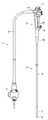
- FIG. 1 is an overall view of an endoscope
- FIG. 2 is a cross-sectional view of a main portion of an insertion portion
- FIG. 3 is a main portion of a connecting portion between a bending portion and a flexible tube portion
- 4 is an exploded perspective view
- FIG. 4 is a perspective view showing the relationship between the connection base to which the flexible tube is connected and the most proximal bending piece
- FIG. 5 is a cross-sectional view of the main part showing the relationship between the most proximal bending piece and the rivet.
- 6 is a perspective view of the rivet
- FIG. 7 is a plan view showing the relationship between the most proximal bending piece and the coupling cap
- FIG. 8 is a sectional view taken along the line VIII-VIII in FIG.
- An endoscope 1 shown in FIG. 1 includes an insertion portion 2 that is formed in an elongated tube shape and is inserted into a subject such as a body cavity, an operation portion 3 that is connected to the proximal end side of the insertion portion 2, and an operation
- positioned at the front end side of the universal cord 4 are provided as main components.
- the endoscope 1 of the present embodiment is a transnasal endoscope that performs inspection of the upper digestive tract such as the esophagus, stomach, and duodenum via the nose of the subject.
- the outer diameter of 2 is a small diameter of about 5 mm.
- the insertion portion 2 of the endoscope 1 includes, in order from the distal end side along the longitudinal direction, a distal end portion 6, a bending portion 7 connected to the proximal end side of the distal end portion 6, and a proximal end of the bending portion 7. And a long flexible tube portion 8 continuously provided on the side.
- the operation unit 3 covers the proximal end of the flexible tube unit 8 and is connected to the flexible tube unit 8, and the operation unit 3 is connected to the folding unit 3 a, and the user uses the endoscope 1. And a gripping portion 3b that is gripped by a hand.
- Various operation members are disposed on the proximal end side of the grasping portion 3b, and a treatment instrument insertion port 9 for guiding a treatment instrument such as forceps into the body cavity is provided on the distal end side of the grasping portion 3b.
- the bending operation knob 10 As an operation member provided in the operation unit 3, there is a bending operation knob 10 for performing the bending operation of the bending unit 7 described above.
- the bending operation knob 10 pulls or relaxes the bending operation wire 40 as a long object inserted over the entire length in the insertion portion 2 in accordance with a user operation input, for example, the bending portion 7.
- the up and down direction and the left and right direction of the bending portion 7 and the like are associated with, for example, the up and down direction and the left and right direction of an image captured by an imaging unit (not shown) built in the tip portion 6. Is defined.
- the bending operation knob 10 is provided with a bending fixing lever 11 for fixing the bending state of the bending portion 7. Furthermore, as operation members provided in the operation unit 3, a plurality of operation switches for performing operations corresponding to air / water supply operations or suction operations, imaging, illumination, and the like are provided.
- the universal cord 4 passes through the inside of the bending portion 7 and the flexible tube portion 8 from the distal end of the insertion portion 2 to the operation portion 3, and further inserts various signal lines and the like extending from the operation portion 3.
- a light guide for transmitting illumination light of a light source device (not shown) is inserted, and an air / water supply tube extending from an air / water supply device (not shown) is further provided. It is a composite cable.
- the connector 5 provided at the extending end of the universal cord 4 is connected to various devices such as a signal processing device (video processor) light source device, an air / water supply device, and other peripheral devices.
- the endoscope 1 constitutes an endoscope system together with various device groups.
- the distal end portion 6 positioned at the distal end of the insertion portion 2 is configured to have a distal end configuration portion (hereinafter referred to as a distal end rigid portion) 20 that is a rigid cylindrical frame.
- the distal end hard portion 20 includes an illumination optical system for illuminating the inside of the subject, an imaging unit, and the like, and an air / water supply channel and forceps for supplying fluid to the target portion in the subject.
- a treatment instrument insertion channel or the like from which a treatment instrument is derived is opened at the distal end surface (none of which is shown).
- the most advanced bending piece 22 located at the most distal end of the bending piece set 21 described later is fixed to the proximal end side of the distal end hard portion 20.
- a plurality of bending pieces 23 for constituting a bending piece set 21 which is a bending structure is disposed inside the bending portion 7.
- the plurality of bending pieces 23 are arranged in a line along the longitudinal axis (center axis O) on the proximal end side of the most advanced bending piece 22.
- the most proximal end bending piece 24 as a first tubular body having a substantially cylindrical shape is disposed on the proximal end side of the piece row composed of a plurality of bending pieces 23 (that is, the most proximal end of the bending piece set 21).
- the most advanced bending piece 22, the plurality of bending pieces 23, and the most proximal bending piece 24 are rotated by a rivet 25, which is a pivot member, at a portion where adjacent connecting portions overlap each other at positions corresponding to the vertical and horizontal directions.
- a bending structure is formed that can be bent in four directions perpendicular to the upper and lower sides and the right and left sides.
- the rivet 25 has a flange-like side of the head arranged on the inner diameter side of the bending piece set 21 in order to prevent the rivet 25 from protruding to the outer shape side.
- the cutting edge bending piece 22 is provided with a wire fixing portion 22a for fixing one end of the wire 40 on the distal end side.
- the wire fixing portions 22a are provided at four locations on the inner peripheral side of the most advanced bending piece 22 corresponding to the four wires 40 for bending operation in the four directions of up and down and left and right.
- annular guide rings 23 a and 24 a are provided at appropriate positions on the inner peripheral side of each bending piece 23 and the most proximal bending piece 24.
- Each guide ring 23a, 24a is inserted into the middle of each wire 40 having a distal end fixed to the wire fixing portion 22a, and the base end side of each wire 40 is connected to the bending operation knob 10 of the operation portion 3 (see FIG. (Not shown).
- the bending portion 7 bends in any of the vertical and horizontal directions.
- the bending portion 7 has a bending structure formed by connecting a plurality of bending pieces 23 in the longitudinal axis direction, and pulling operation by the wires 40 from the operation portion 3 in four directions perpendicular to the upper and lower sides and the left and right. Actively curves with input.
- the outer periphery of the plurality of bending pieces 23 is covered with a net-like blade 15 formed by braiding a metal or non-metallic fine wire. Further, the outer periphery of the blade 15 is covered with a curved rubber 17, and an outer skin from the distal end portion 6 to the curved portion 7 is formed by the curved rubber 17.
- the curved rubber 17 is fixed to the outer periphery of the distal end portion 6 in a watertight manner, but other portions along the insertion direction are the most advanced bending piece 22, the plurality of bending pieces 23, and the most proximal end.
- the outer periphery of the bending piece 24 is covered with no adhesion.
- a spiral tube (flex) 30 configured by spirally winding a band-shaped member is disposed inside the flexible tube portion 8.
- the outer periphery of the spiral tube 30 is covered with a mesh blade (mesh tube) 31 formed by braiding a metal or non-metallic fine wire.
- the outer periphery of the blade 31 is covered with an outer skin 32, and the distal end side of the outer skin 32 is liquid-tightened by a bobbin adhering portion 33 on the proximal end side of the curved rubber 17 extending to the flexible tube portion 8 side. It is connected.
- connection cap 35 as a second tubular body having a substantially cylindrical shape is connected to the tip of the spiral tube 30 covered with the blade 31.
- the distal ends of four guide sheaths 41 as wire guide members into which the four wires 40 are inserted so as to be able to advance and retreat are fixed to the inner periphery of the coupling base 35 by brazing or the like.
- the guide sheath 41 is formed as a flexible coil pipe formed by tightly winding a stainless steel wire, for example, and is inserted through the inner peripheral side of the flexible tube portion 8 of the insertion portion 2.
- connection base 35 is connected to the inner periphery on the proximal end side of the most proximal end bending piece 24, thereby configuring the spiral tube 30 constituting the flexible tube portion 8 and the bending portion 7. Connection with the bending piece set 21 is realized.
- the most proximal bending piece 24 has a substantially cylindrical tip side region 45 and a larger diameter than the tip side region 45.
- forms the substantially cylindrical shape formed is comprised by the cylindrical part with the step provided in a row.
- the distal end region 45 of the most proximal bending piece 24 is provided with a connecting portion 45a with the adjacent bending piece 23 and the above-described guide ring 24a.
- a through hole 46a penetrating in the thickness direction of the most proximal end bending piece 24 that is, from the inner peripheral side to the outer peripheral side of the most proximal end bending piece 24. (See FIGS. 3 and 5 etc.).
- a rivet 47 is held in the through hole 46a.
- the shaft portion 47 a is inserted into the through hole 46 a from the inner peripheral side of the most proximal end bending piece 24, and the tip of the shaft portion 47 a is caulked on the outer peripheral side of the most proximal end bending piece 24. It is held in the hole 46a.
- the head 47b having a flange-like shape in the rivet 47 is disposed so as to protrude toward the inner periphery of the most proximal end bending piece 24, thereby realizing a function as a protrusion.
- the rivet 47 is provided with a slit 47c in a portion from the head 47b to a part of the shaft portion 47a.
- the slit 47c is positioned so as to extend in a direction orthogonal to the central axis O of the most proximal bending piece 24 when the rivet 47 is held in the through hole 46a.
- the head 47b of the rivet 47 can be elastically deformed in the direction of the central axis O within the range allowed by the slit 47c.
- connection cap 35 is, for example, a stepped portion in which a distal end side region 50 having a substantially cylindrical shape and a proximal end side region 51 having a substantially cylindrical shape formed in a larger diameter than the distal end side region 50 are connected. It is comprised by the cylindrical part.
- the distal end side region 50 of the coupling base 35 has an outer diameter smaller than the inner diameter of the proximal end side region 46 of the most proximal end bending piece 24, and slides inside the most proximal end bending piece 24 along the central axis O. It has a function as a movable sliding part.
- the tip end of the above-described guide sheath 41 is fixed to the inner periphery of the tip end side region 50 of the coupling base 35 (see FIG. 4).
- the coupling cap 35 is provided with an engagement groove 52 that can receive and engage the head 47b of the rivet 47 held by the most proximal bending piece 24.
- the engagement groove 52 is a through groove penetrating in the thickness direction of the coupling base 35, and a first groove portion 52 a that slides the head 47 b of the rivet 47 from one end side to the other end side of the coupling base 35,
- the rivet 47 is constituted by a substantially L-shaped groove having a second groove portion 52b that slides the head portion 47b of the rivet 47 in a direction intersecting with the direction along the central axis O of the coupling base 35.
- the first groove 52 a has substantially the same groove width as the head 47 b of the rivet 47, and is constituted by a groove extending along the central axis O from the distal end side to the proximal end side of the connection cap 35. .
- One end of the first groove 52 a is opened at the tip of the connection base 35.
- the extending direction of the first groove portion 52a does not necessarily coincide with the central axis O, and the main component of the extending direction may be the direction of the central axis O.
- the second groove portion 52b basically has the same groove width as the head portion 47b of the rivet 47, and is configured by a groove portion extending along the circumferential direction of the coupling base 35 orthogonal to the central axis O. .
- One end of the second groove portion 52b communicates with the other end of the first groove portion 52a.
- the other end of the second groove portion 52b is closed in a bag shape, whereby an end face for abutting the head portion 47b of the rivet 47 is formed at the other end of the second groove portion 52b.
- a narrowed portion 52c in which the groove width is partially narrowed is formed in the middle of the second groove portion 52b.
- the extending direction of the second groove 52b is not necessarily required to be completely coincident with the direction orthogonal to the central axis O, and may be any direction in which the main component of the extending direction is orthogonal to the central axis O.
- the engagement groove 52 having such a configuration is, for example, when the head portion 47b of the rivet 47 held by the most proximal end bending piece 24 is positioned at the other end of the second groove portion 52b (when it hits).
- the pair of guide rings 24a provided on the most proximal end bending piece 24 and the distal ends of the guide sheaths 41 corresponding to the guide rings 24a are set so as to be positioned coaxially or substantially coaxially, respectively. Yes.
- the pair of guide rings 24a has a function as a first receiving portion, and the pair of guide sheaths 41 corresponding to the pair of guide rings 24a functions as a second receiving portion.
- the distal end of the spiral tube 30 covered with the blade 31 is coupled to the inner periphery of the proximal end side region 51 of the coupling base 35.
- the outer peripheral surface of the distal end side region 50 of the coupling base 35 is pushed into the inner peripheral surface of the proximal end region 46 of the most proximal end bending piece 24 while sliding in the direction of the central axis O. 47b and the first groove portion 52a are slid, and the head portion 47b of the rivet 47 is relatively moved toward the base end side (the other end side) of the first groove portion 52a.
- the inner peripheral surface of the proximal end side region 46 of the most proximal end bending piece 24 and the outer peripheral surface of the distal end side region 50 of the coupling base 35 are relatively rotated while sliding around the central axis O, whereby the rivet 47
- the head 47b and the second groove 52b are slid, and the head 47b of the rivet 47 is relatively moved to the base end side (the other end side) of the second groove 52b.
- the head portion 47b of the rivet 47 slides while elastically deforming in the diameter reducing direction at the throttle portion 52c, or the head portion 47c is slid while elastically deforming the periphery of the throttle portion 52c.
- the pair of guide rings 24a provided on the most proximal end bending piece 24 and the pair of guide sheaths 41 corresponding to these guide rings 24a are arranged coaxially (see FIG. 2).
- the proximal end side region 46 of the most proximal end bending piece 24 having the center axis O and the outer diameter smaller than the proximal end side region 46 of the most proximal end bending piece 24,
- a distal end side region 50 of the coupling base 35 slidable inside the proximal end side region 46 of the most proximal end bending piece 24 along the axis O, and an inner peripheral surface of the proximal end side region 46 of the most proximal end bending piece 24.
- the head portion 47b of the rivet 47 is accommodated to receive a base from the distal end side.
- the first groove 52a to be slid to the end side and the first groove 52 are communicated, and the head 47b of the rivet 47 is accommodated and slid in a direction intersecting with the direction along the central axis O and slid
- an endoscope such as a nasal endoscope needs to reduce the diameter of the insertion portion 2, but the head 47 b of the rivet 47 that engages with the engagement groove 52 is attached to the proximal end bending piece 24.
- the head 47 b of the rivet 47 that engages with the engagement groove 52 is attached to the proximal end bending piece 24.
- the coupling mechanism using the head 47b of the rivet 47 as a protrusion, the thickness of the proximal end bending piece 24 and the coupling base 35 cannot be screwed (that is, the thread cannot be formed). Even when the thickness is reduced to a small dimension), the connection between the most proximal bending piece 24 and the connection base 35 can be accurately realized.
- a tongue piece 55 is projected at the proximal end of the most proximal bending piece 24, and this tongue piece It is also possible to form a protrusion (folded portion) by folding 55 to the inner peripheral side.
- This configuration can further simplify the connection structure. Furthermore, the length of the proximal end region 51 in the direction of the central axis O can be shortened, and the length of the connection region in which bending or the like is impossible can be shortened.
- the length of the proximal end region 51 in the direction of the central axis O is shortened and partially protruded from the proximal end region 51.
- 57 can be formed, and the rivet 47 can be partly projected from the proximal end of the most proximal bending piece 24 and held.
- the present invention is not limited to the embodiments described above, and various modifications and changes are possible, and these are also within the technical scope of the present invention.
- the example in which the tube connection structure of the present invention is applied to the insertion portion of the nasal endoscope has been described.
- the present invention is not limited to this, and for example, the intranasal endoscope In addition to endoscopes, it may be applied to insertion parts of otolaryngological and urological endoscopes, and may also be applied to catheters having a curved portion composed of bending pieces other than endoscopes. Is possible.
Landscapes
- Physics & Mathematics (AREA)
- Health & Medical Sciences (AREA)
- Engineering & Computer Science (AREA)
- Life Sciences & Earth Sciences (AREA)
- Surgery (AREA)
- Optics & Photonics (AREA)
- General Engineering & Computer Science (AREA)
- Heart & Thoracic Surgery (AREA)
- Medical Informatics (AREA)
- Radiology & Medical Imaging (AREA)
- General Physics & Mathematics (AREA)
- Astronomy & Astrophysics (AREA)
- Biomedical Technology (AREA)
- Nuclear Medicine, Radiotherapy & Molecular Imaging (AREA)
- Pathology (AREA)
- Molecular Biology (AREA)
- Animal Behavior & Ethology (AREA)
- General Health & Medical Sciences (AREA)
- Public Health (AREA)
- Veterinary Medicine (AREA)
- Biophysics (AREA)
- Mechanical Engineering (AREA)
- Endoscopes (AREA)
Abstract
Description
本発明は、内視鏡やカテーテルの挿入部等を構成する細径な管状体を連結するために好適な管連結構造に関する。 The present invention relates to a tube connection structure suitable for connecting a thin tubular body constituting an insertion portion of an endoscope or a catheter.
従来、医療分野等において用いられる内視鏡やカテーテルの挿入部等は、細径且つ長尺な管状構造体を用いて構成されている。このような管状構造体は、各種機能を実現するための複数の管状体が長手軸(中心軸)に沿って連結されることによって構成されている。これにより、挿入部には、先端部、湾曲部、及び、可撓管部等の各種機能部が構成されている。 2. Description of the Related Art Conventionally, endoscopes and catheter insertion portions used in the medical field and the like are configured using a thin and long tubular structure. Such a tubular structure is configured by connecting a plurality of tubular bodies for realizing various functions along a longitudinal axis (center axis). Thereby, various functional parts, such as a front-end | tip part, a bending part, and a flexible tube part, are comprised in the insertion part.
このような管状体を連結するための技術として、例えば、日本国特開2017-129229号公報の図5等には、外周側にピン(突起)が突出する雄型継手と連結する雌型継手のスリーブに、周方向に延びる周方向中間通路と、周方向中間通路の一端から前方に延在する長手方向前方通路と、周方向中間通路の他端柄公報に延在する長手方向後方通路と、を備えたピン受入通路(溝部)を設け、このピン受入通路に雄型継手のピンを係合させることにより、2つの配管を連結する技術が開示されている。 As a technique for connecting such tubular bodies, for example, in FIG. 5 of Japanese Patent Application Laid-Open No. 2017-129229, a female joint for connecting with a male joint with a pin (protrusion) protruding on the outer peripheral side is shown. A circumferential intermediate passage extending in the circumferential direction, a longitudinal front passage extending forward from one end of the circumferential intermediate passage, and a longitudinal rear passage extending in the other end pattern of the circumferential intermediate passage. , A technology for connecting two pipes by providing a pin receiving passage (groove) with a male joint pin in the pin receiving passage.
しかしながら、内視鏡の挿入部等は外径が5mm以下となるような細径なものが多く存在し、特に、このような細径の挿入部の管状構造体では、各管状体の肉厚が極めて薄くなる。 However, there are many endoscope insertion portions and the like having an outer diameter of 5 mm or less, and in particular, in the tubular structure of such a thin insertion portion, the thickness of each tubular body Becomes extremely thin.
従って、このような薄肉な管状体の連結に上述の日本国特開2017-129229号公報の技術を適用した場合、外周側に突出する突起を溝部に係合させる際に、溝部側の管状体の端部等が突起によって外周方向に変形し、湾曲ゴムやブレード等の外装部材を損傷させる虞がある。 Therefore, when the technique disclosed in Japanese Patent Application Laid-Open No. 2017-129229 is applied to the connection of such thin-walled tubular bodies, the tubular body on the groove side is used when the protrusion protruding toward the outer periphery is engaged with the groove. There is a possibility that the end portion of the outer peripheral portion is deformed in the outer peripheral direction by the protrusion and damages the exterior member such as the curved rubber or the blade.
本発明は上記事情に鑑みてなされたもので、薄肉な管状体を良好な連結状態にて的確に連結することができる管連結構造を提供することを目的とする。 The present invention has been made in view of the above circumstances, and an object thereof is to provide a pipe connection structure capable of accurately connecting thin tubular bodies in a good connection state.
本発明の一態様による管連結構造は、中心軸を有する第1管状体と、前記第1管状体の内径より小さい外径を有し、前記中心軸に沿って前記第1管状体の内部に摺動可能な摺動部を有する、前記中心軸に沿って一端から他端に延出する第2管状体と、前記第1管状体の内周面から前記中心軸の方向に向けて突出した部分を有する、前記第1管状体に設けられた突起と、前記第2管状体の前記摺動部に設けられ、前記突起を収めて前記突起を前記一端側から他端側に摺動させる第1の溝部と、前記第2管状体の前記摺動部に前記第1の溝部と連通して設けられ、前記突起を収めて前記突起を前記中心軸に沿った方向と交わる方向に摺動させるとともに、摺動した前記突起を突き当てる端面を有する第2の溝部と、を有するものである。 A pipe connection structure according to an aspect of the present invention includes a first tubular body having a central axis, an outer diameter smaller than an inner diameter of the first tubular body, and the inside of the first tubular body along the central axis. A second tubular body having a slidable sliding portion and extending from one end to the other along the central axis, and projecting from the inner peripheral surface of the first tubular body toward the central axis A projection provided on the first tubular body having a portion and a sliding portion provided on the sliding portion of the second tubular body, wherein the projection is received and the projection is slid from the one end side to the other end side. 1 groove portion and the sliding portion of the second tubular body are provided in communication with the first groove portion, the protrusion is received, and the protrusion is slid in a direction intersecting the direction along the central axis. And a second groove portion having an end surface against which the slid protrusion is abutted.
以下、図面を参照して本発明の形態を説明する。図面は本発明の一実施形態に係り、図1は内視鏡の全体図、図2は挿入部の要部断面図、図3は湾曲部と可撓管部との連結部分の要部を示す分解斜視図、図4は可撓管が連結された連結口金と最基端湾曲駒との関係を示す斜視図、図5は最基端湾曲駒とリベットとの関係を示す要部断面図、図6はリベットの斜視図、図7は最基端湾曲駒と連結口金との関係を示す平面図、図8は図7のVIII-VIII断面図である。 Hereinafter, embodiments of the present invention will be described with reference to the drawings. The drawings relate to an embodiment of the present invention, FIG. 1 is an overall view of an endoscope, FIG. 2 is a cross-sectional view of a main portion of an insertion portion, and FIG. 3 is a main portion of a connecting portion between a bending portion and a flexible tube portion. 4 is an exploded perspective view, FIG. 4 is a perspective view showing the relationship between the connection base to which the flexible tube is connected and the most proximal bending piece, and FIG. 5 is a cross-sectional view of the main part showing the relationship between the most proximal bending piece and the rivet. 6 is a perspective view of the rivet, FIG. 7 is a plan view showing the relationship between the most proximal bending piece and the coupling cap, and FIG. 8 is a sectional view taken along the line VIII-VIII in FIG.
図1に示す内視鏡1は、細長管状に形成されて体腔内等の被検体内に挿入される挿入部2と、挿入部2の基端側に連設された操作部3と、操作部3の側部から延出されるユニバーサルコード4と、ユニバーサルコード4の先端側に配設されたコネクタ5と、を主要構成として備えている。
An endoscope 1 shown in FIG. 1 includes an
なお、本実施形態の内視鏡1は、例えば、被検体の鼻を経由して食道・胃・十二指腸などの上部消化管の検査等を行う経鼻内視鏡であり、このため、挿入部2の外径は5mm程度の細径となっている。 Note that the endoscope 1 of the present embodiment is a transnasal endoscope that performs inspection of the upper digestive tract such as the esophagus, stomach, and duodenum via the nose of the subject. The outer diameter of 2 is a small diameter of about 5 mm.
内視鏡1の挿入部2は、長手方向に沿って先端側から順に、先端部6と、この先端部6の基端側に連設された湾曲部7と、この湾曲部7の基端側に連設された長尺な可撓管部8と、を備えて構成されている。
The
操作部3は、可撓管部8の基端を覆って可撓管部8と接続される折れ止部3aと、この折れ止部3aに連設され、使用者が内視鏡1を使用するときに手によって把持される把持部3bと、を有している。
The
把持部3bの基端側には各種の操作部材が配設され、把持部3bの先端側には鉗子などの処置具を体腔内に導くための処置具挿通口9などが設けられている。
Various operation members are disposed on the proximal end side of the
操作部3に設けられた操作部材としては、上述の湾曲部7の湾曲操作を行う湾曲操作ノブ10がある。この湾曲操作ノブ10は、使用者の操作入力に応じて、挿入部2内の全長に渡って挿入される長尺物としての湾曲操作ワイヤ40を牽引或いは弛緩させることにより、例えば、湾曲部7を上下及び左右の4方向(全周方向)に能動的に湾曲させることが可能となっている。
As an operation member provided in the
なお、本実施形態において、湾曲部7等の上下方向及び左右方向とは、例えば、先端部6に内蔵された撮像ユニット(不図示)によって撮像された画像の上下方向及び左右方向に対応付けて定義されるものである。
In the present embodiment, the up and down direction and the left and right direction of the
また、湾曲操作ノブ10には湾曲部7の湾曲状態を固定する湾曲固定レバー11が併設されている。さらに、操作部3に設けられる操作部材として、送気送水操作または吸引操作、撮像、照明などに対応した操作を行うための複数の操作スイッチなどが設けられている。
Also, the
ユニバーサルコード4は、挿入部2の先端から湾曲部7及び可撓管部8の内部を挿通して操作部3に至り、さらに操作部3から延出する各種信号線などを内部に挿通する。
The
このユニバーサルコード4には、光源装置(図示せず)の照明光伝送用のライトガイドを挿通し、さらに送気送水装置(図示せず)から延出される送気送水用チューブが配設された複合ケーブルである。
In this
ユニバーサルコード4の延出端に設けられたコネクタ5は、各種装置、例えば、信号処理装置(ビデオプロセッサ)光源装置、送気送水装置、その他の周辺装置に接続される。これにより、内視鏡1は、各種装置群とともに、内視鏡システムを構成する。
The
次に、挿入部2の先端側の内部構成について説明する。
Next, the internal configuration on the distal end side of the
図2に示すように、挿入部2の先端に位置する先端部6は、硬質な筒状のフレームである先端構成部(以後、先端硬質部)20を有して構成されている。この先端硬質部20は、被検体内を照明するための照明光学系、撮像ユニット等が内部に配設されるとともに、被検体内の対象部位に対して流体を供給する送気送水チャンネル、鉗子などの処置具が導出される処置具挿通チャンネル等が先端面に開口されている(何れも図示せず)。
As shown in FIG. 2, the
先端部6の内部において、先端硬質部20の基端側には、後述する湾曲駒組21の最先端に位置する最先端湾曲駒22が固定されている。
Inside the
湾曲部7の内部には、湾曲構造体である湾曲駒組21を構成するための複数の湾曲駒23が配設されている。これら複数の湾曲駒23は、最先端湾曲駒22の基端側において、長手軸(中心軸O)に沿って一列に配列されている。さらに、複数の湾曲駒23からなる駒列の基端側(すなわち、湾曲駒組21の最基端)には、略円筒形状をなす第1管状体としての最基端湾曲駒24が配設されている。
Inside the
これら最先端湾曲駒22、複数の湾曲駒23、及び、最基端湾曲駒24は、上下および左右に対応する位置で隣接する連結部同士が重なった部位を枢支部材であるリベット25によって回動自在に連結することにより、上下および左右の互いに直交する4方向に湾曲自在な湾曲構造を形成している。なお、リベット25は、外形側への突出を防ぐため、頭部のうちフランジ状の形状を有する側が湾曲駒組21の内径側に配置されている。
The most
ここで、最先端湾曲駒22には、ワイヤ40の先端側の一端を固定するためのワイヤ固定部22aが設けられている。本実施形態において、ワイヤ固定部22aは、上下及び左右の4方向の湾曲動作用の4本のワイヤ40に対応して最先端湾曲駒22の内周側の4箇所に設けられている。
Here, the cutting
また、各湾曲駒23及び最基端湾曲駒24の内周側の適所には、環状のガイドリング23a,24aが設けられている。各ガイドリング23a,24aには、ワイヤ固定部22aに先端が固定された各ワイヤ40の中途が挿通され、各ワイヤ40の基端側が操作部3の湾曲操作ノブ10に連結されたスプロケット(図示せず)に巻回されている。
Further, annular guide rings 23 a and 24 a are provided at appropriate positions on the inner peripheral side of each
これにより、湾曲操作ノブ10によって4本のワイヤ40の何れかが牽引操作されると、湾曲部7が上下及び左右の何れかの方向に湾曲動作する。
Thus, when any of the four
即ち、湾曲部7は、複数の湾曲駒23を長手軸方向に連結することにより、湾曲構造が形成され、上下および左右の互いに直交する4方向に、操作部3からの各ワイヤ40による牽引操作入力によって能動的に湾曲する。
That is, the
一方、複数の湾曲駒23の外周には、金属または非金属の細線材を編組して形成される網状のブレード15が被覆されている。さらに、ブレード15の外周には、湾曲ゴム17が被覆され、この湾曲ゴム17により、先端部6から湾曲部7にかけての外皮が形成されている。
On the other hand, the outer periphery of the plurality of bending
尚、湾曲ゴム17は、先端部6の外周には水密に接着固定されているが、その他の挿入方向に沿った部位は、最先端湾曲駒22、複数の湾曲駒23、及び、最基端湾曲駒24の外周に対して非接着にて被覆されている。
The
可撓管部8の内部には、例えば、帯状部材を螺旋状に巻回して構成された螺旋管(フレックス)30が配設されている。
Inside the
この螺旋管30の外周には、金属または非金属の細線材を編組して形成される網状のブレード(網状管)31が被覆されている。
The outer periphery of the
また、ブレード31の外周には外皮32が被覆され、この外皮32の先端側は、可撓管部8側に延設された湾曲ゴム17の基端側に、糸巻接着部33によって液密に接続されている。
Further, the outer periphery of the
また、ブレード31によって被覆された螺旋管30の先端には、略円筒形状をなす第2管状体としての連結口金35が接続されている。
Further, a
連結口金35の内周には、4本のワイヤ40のそれぞれが進退自在に挿通されるワイヤガイド部材としての4本のガイドシース41の先端がロウ付けなどで固定されている。
The distal ends of four
ガイドシース41は、例えば、ステンレス鋼線を密着巻きする等して形成される柔軟なコイルパイプとして形成され、挿入部2の可撓管部8の内周側に挿通されている。
The
また、連結口金35の先端側の外周には最基端湾曲駒24の基端側の内周が連結され、これにより、可撓管部8を構成する螺旋管30と、湾曲部7を構成する湾曲駒組21と、の連結が実現されている。
Further, the outer periphery on the distal end side of the
具体的に説明すると、例えば、図3~5,7,8に示すように、最基端湾曲駒24は、略円筒形状をなす先端側領域45と、この先端側領域45よりも大径に形成された略円筒形状をなす基端側領域46と、が連設された段付きの筒状部品によって構成されている。
More specifically, for example, as shown in FIGS. 3 to 5, 7, and 8, the most
この最基端湾曲駒24の先端側領域45には、隣接する湾曲駒23との連結部45aが設けられているとともに、上述したガイドリング24aが設けられている。
The
また、最基端湾曲駒24の基端側領域46には、最基端湾曲駒24の肉厚方向(すなわち、最基端湾曲駒24の内周側から外周側)に貫通する貫通孔46aが設けられている(図3,5等参照)。
Further, in the proximal
この貫通孔46aには、リベット47が保持されている。このリベット47は、軸部47aが最基端湾曲駒24の内周側から貫通孔46aに挿通され、当該軸部47aの先端が最基端湾曲駒24の外周側においてカシメられることにより、貫通孔46aに保持されている。これにより、リベット47のうちフランジ状の形状を有する頭部47bは、最基端湾曲駒24の内周に向けて突出するように配置され、突起としての機能を実現する。
A
ここで、例えば、図6に示すように、リベット47には、頭部47bから軸部47aの一部にかけての部分にスリット47cが設けられている。このスリット47cは、リベット47が貫通孔46aに保持される際に、最基端湾曲駒24の中心軸Oと直交する方向に延在するように位置決めされている。これにより、リベット47の頭部47bは、スリット47cの許容する範囲内において、中心軸O方向に弾性変形することが可能となっている。
Here, for example, as shown in FIG. 6, the
連結口金35は、例えば、略円筒形状をなす先端側領域50と、この先端側領域50よりも太径に形成された略円筒形状をなす基端側領域51と、が連設された段付きの筒状部品によって構成されている。
The
この連結口金35の先端側領域50は、最基端湾曲駒24の基端側領域46の内径よりも小さい外径を有し、中心軸Oに沿って最基端湾曲駒24の内部に摺動可能な摺動部としての機能を有する。
The distal
また、連結口金35の先端側領域50の内周には、上述のガイドシース41の先端が固定されている(図4参照)。
Further, the tip end of the above-described
また、連結口金35には、最基端湾曲駒24に保持されたリベット47の頭部47bを受容して係合可能な係合溝52が設けられている。この係合溝52は、連結口金35の肉厚方向に貫通する貫通溝であり、リベット47の頭部47bを連結口金35の一端側から他端側に摺動させる第1の溝部52aと、リベット47の頭部47bを連結口金35の中心軸Oに沿った方向と交わる方向に摺動させる第2の溝部52bと、を有する略L字状の溝によって構成されている。
Further, the
すなわち、第1の溝部52aは、リベット47の頭部47bと略同じ溝幅を有し、中心軸Oに沿って連結口金35の先端側から基端側に延在する溝部によって構成されている。この第1の溝部52aの一端は、連結口金35の先端において開口されている。なお、第1の溝部52aの延在方向は、必ずしも中心軸Oと完全に一致させる必要はなく、延在方向の主な成分が中心軸Oの方向であればよい。
That is, the
第2の溝部52bは、基本的にはリベット47の頭部47bとほぼ同じ溝幅を有し、中心軸Oと直交する連結口金35の周方向に沿って延在する溝部によって構成されている。この第2の溝部52bの一端は、第1の溝部52aの他端と連通されている。また、第2の溝部52bの他端は袋状に閉塞され、これにより、第2の溝部52bの他端にはリベット47の頭部47bを突き当てるための端面が形成されている。さらに、第2の溝部52bの中途には、溝幅が一部狭くなる絞り部52cが形成されている。なお、第2の溝部52bの延在方向は、必ずしも中心軸Oに直交する方向と完全に一致させる必要はなく、延在方向の主な成分が中心軸Oに直交する方向であればよい。
The
ここで、このような構成の係合溝52は、例えば、最基端湾曲駒24に保持されたリベット47の頭部47bが第2の溝部52bの他端に位置するとき(突き当たったとき)、最基端湾曲駒24に設けられた一対のガイドリング24aと、これらのガイドリング24aに対応する各ガイドシース41の先端と、をそれぞれ同軸上または略同軸上に位置させるように設定されている。このように、本実施形態において、一対のガイドリング24aは第1の受け部としての機能を有し、これら一対のガイドリング24aに対応する一対のガイドシース41は第2の受け部としての機能を有する。
Here, the
連結口金35の基端側領域51の内周には、ブレード31が被覆された螺旋管30の先端が連結されている。
The distal end of the
このような構成において、湾曲部7を構成する湾曲駒組21と可撓管部8を構成する螺旋管30とを連結する際には、リベット47の頭部47bと第1の溝部52aの開口との位置決めがなされた状態にて、最基端湾曲駒24の基端側領域46の内周に連結口金35の先端側領域50が挿入される。
In such a configuration, when the bending piece set 21 constituting the bending
そして、最基端湾曲駒24の基端側領域46の内周面に連結口金35の先端側領域50の外周面が中心軸O方向に摺動しながら押し込まれることにより、リベット47の頭部47bと第1の溝部52aとが摺動され、当該リベット47の頭部47bが第1の溝部52aの基端側(他端側)へと相対移動される。
Then, the outer peripheral surface of the distal
その後、最基端湾曲駒24の基端側領域46の内周面と連結口金35の先端側領域50の外周面とが中心軸O周りに摺動しながら相対回転されることにより、リベット47の頭部47bと第2の溝部52bとが摺動され、当該リベット47の頭部47bが第2の溝部52bの基端側(他端側)へと相対移動される。その際、リベット47の頭部47bは、絞り部52cにおいて縮径方向に弾性変形しながら摺動し、又は絞り部52cの周囲が弾性変形しながら頭部47cを摺動させ、絞り部52cを通過して第2の溝部52bの他端に突き当たったとき、絞り部52cから解放されて拡径方向に復元される。これにより、最基端湾曲駒24と連結口金35との相対回転が禁止され、これらの連結状態が維持される。
Thereafter, the inner peripheral surface of the proximal
なお、このとき最基端湾曲駒24に設けられた一対のガイドリング24aと、これらのガイドリング24aに対応する一対のガイドシース41は、それぞれ同軸上に配置される(図2参照)。
At this time, the pair of
このような実施形態によれば、中心軸Oを有する最基端湾曲駒24の基端側領域46と、最基端湾曲駒24の基端側領域46よりも小さい外径を有し、中心軸Oに沿って最基端湾曲駒24の基端側領域46の内部に摺動可能な連結口金35の先端側領域50と、最基端湾曲駒24の基端側領域46の内周面から中心軸Oの方向に向けて突出するように固定されたリベット47の頭部47bと、連結口金35の先端側領域50に設けられ、リベット47の頭部47bを収容して先端側から基端側に摺動させる第1の溝部52a、及び、第1の溝部と連通し、リベット47の頭部47bを収容して中心軸Oに沿った方向と交わる方向に摺動させるとともに、摺動した頭部47bを突き当てる端面を有する第2の溝部52bと、を有することにより、薄肉な管状体管状体を良好な連結状態にて的確に連結することができる。
According to such an embodiment, the proximal
すなわち、例えば、経鼻内視鏡等の内視鏡は挿入部2を細径化する必要があるが、係合溝52に係合するリベット47の頭部47bを最基端湾曲駒24の基端側領域46の内周面側に突出させることにより、挿入部2の細径化を阻害することなく、湾曲駒組21と螺旋管30との連結構造を実現することができる。加えて、挿入部2の細径化のためには最基端湾曲駒24や連結口金35等の管状体の肉厚が必然的に薄肉化されるが、このような場合であっても、最基端湾曲駒24の基端側領域46の内部に挿入される連結口金35の先端側領域50に係合溝52(第1の溝部52a及び第2の溝部52b)を設けることにより、仮に、リベット47の頭部47bとの係合時に第1の溝部52aの開口近傍で連結口金35が変形される等した場合にも変形した連結口金35のエッジ等によってブレード15や湾曲ゴム17等を損傷させることのない連結構造を実現することができる。
That is, for example, an endoscope such as a nasal endoscope needs to reduce the diameter of the
また、リベット47の頭部47bを突起として利用して連結機構を構成することにより、最基端湾曲駒24及び連結口金35の肉厚をネジ止めが不能な寸法(すなわち、ネジ山を形成不能な寸法)まで薄肉化した場合にも、最基端湾曲駒24と連結口金35との連結を的確に実現することができる。
Further, by configuring the coupling mechanism using the
ここで、他の実施形態として、例えば、図9,10に示すように、リベット47の頭部47bに代えて、最基端湾曲駒24の基端に舌片55を突出させ、この舌片55を内周側に折り返すことにより、突起(折返部)を形成することも可能である。
Here, as another embodiment, for example, as shown in FIGS. 9 and 10, instead of the
このように構成すれば、連結構造をより簡素化することができる。さらに、基端側領域51の中心軸O方向の長さを短縮することができ、湾曲等が不能となる連結領域の長さを短縮することができる。
This configuration can further simplify the connection structure. Furthermore, the length of the
或いは、更に他の実施形態として、例えば、図11,12に示すように、基端側領域51の中心軸O方向の長さを短縮し、基端側領域51から一部突出させた突出部57を形成し、リベット47を最基端湾曲駒24の基端から一部突出させて保持することも可能である。
Alternatively, as still another embodiment, for example, as shown in FIGS. 11 and 12, the length of the
なお、本発明は、以上説明した各実施形態に限定されることなく、種々の変形や変更が可能であり、それらも本発明の技術的範囲内である。例えば、上述の実施形態においては、経鼻内視鏡の挿入部に本発明の管接続構造を適用した一例について説明したが、本発明はこれに限定されるものではなく、例えば、経鼻内視鏡以外にも耳鼻科用や泌尿器用の内視鏡の挿入部に対して適用してもよく、内視鏡以外の湾曲駒により構成される湾曲部を有するカテーテル等に対しても適用が可能である。 The present invention is not limited to the embodiments described above, and various modifications and changes are possible, and these are also within the technical scope of the present invention. For example, in the above-described embodiment, the example in which the tube connection structure of the present invention is applied to the insertion portion of the nasal endoscope has been described. However, the present invention is not limited to this, and for example, the intranasal endoscope In addition to endoscopes, it may be applied to insertion parts of otolaryngological and urological endoscopes, and may also be applied to catheters having a curved portion composed of bending pieces other than endoscopes. Is possible.
本出願は、2018年2月22日に日本国に出願された特願2018-29721号を優先権主張の基礎として出願するものであり、上記の開示内容は、本願明細書、請求の範囲に引用されるものとする。 This application is filed on the basis of the priority claim of Japanese Patent Application No. 2018-29721 filed in Japan on February 22, 2018. The above disclosure is included in the present specification and claims. Shall be quoted.
Claims (8)
前記第1管状体の内径より小さい外径を有し、前記中心軸に沿って前記第1管状体の内部に摺動可能な摺動部を有する、前記中心軸に沿って一端から他端に延出する第2管状体と、
前記第1管状体の内周面から前記中心軸の方向に向けて突出した部分を有する、前記第1管状体に設けられた突起と、
前記第2管状体の前記摺動部に設けられ、前記突起を収めて前記突起を前記一端側から他端側に摺動させる第1の溝部と、
前記第2管状体の前記摺動部に前記第1の溝部と連通して設けられ、前記突起を収めて前記突起を前記中心軸に沿った方向と交わる方向に摺動させるとともに、摺動した前記突起を突き当てる端面を有する第2の溝部と、を有することを特徴とする管連結構造。 A first tubular body having a central axis;
The first tubular body has an outer diameter smaller than the inner diameter, and has a sliding portion that can slide inside the first tubular body along the central axis, from one end to the other end along the central axis. A second tubular body extending;
A protrusion provided on the first tubular body having a portion protruding from the inner peripheral surface of the first tubular body toward the central axis;
A first groove that is provided in the sliding portion of the second tubular body, houses the protrusion, and slides the protrusion from the one end side to the other end side;
The sliding portion of the second tubular body is provided in communication with the first groove, and the projection is received and the projection is slid in a direction intersecting with the direction along the central axis and slid. And a second groove portion having an end face against which the protrusion is abutted.
前記第2管状体の内周部分には、前記長尺物を前記中心軸に沿った方向に摺動可能に支持する第2の受け部を有し、
前記中心軸に沿った方向と交わる方向に摺動した前記突起が前記端面に突き当たったとき、前記第1の受け部と前記第2の受け部とが前記長尺物を同軸又は略同軸になるように支持するように、前記第1の受け部及び前記第2の受け部が配置されることを特徴とする請求項1に記載の管連結構造。 The inner peripheral portion of the first tubular body has a first receiving portion that slidably supports a long object extending in a direction along the central axis,
The inner peripheral portion of the second tubular body has a second receiving portion that slidably supports the elongated object in a direction along the central axis,
When the projection sliding in a direction intersecting with the direction along the central axis hits the end face, the first receiving portion and the second receiving portion make the elongated object coaxial or substantially coaxial. The pipe connection structure according to claim 1, wherein the first receiving portion and the second receiving portion are arranged so as to be supported.
前記第2管状体は前記湾曲駒に対して接続する、前記挿入部に設けられた連結口金であることを特徴とする請求項1に記載の管連結構造。 The first tubular body is a bending piece constituting a bending portion connected to an insertion portion of an endoscope,
The pipe connection structure according to claim 1, wherein the second tubular body is a connection base provided in the insertion portion that is connected to the bending piece.
Applications Claiming Priority (2)
| Application Number | Priority Date | Filing Date | Title |
|---|---|---|---|
| JP2018-029721 | 2018-02-22 | ||
| JP2018029721 | 2018-02-22 |
Publications (1)
| Publication Number | Publication Date |
|---|---|
| WO2019163252A1 true WO2019163252A1 (en) | 2019-08-29 |
Family
ID=67687543
Family Applications (1)
| Application Number | Title | Priority Date | Filing Date |
|---|---|---|---|
| PCT/JP2018/044757 Ceased WO2019163252A1 (en) | 2018-02-22 | 2018-12-05 | Pipe connection structure |
Country Status (1)
| Country | Link |
|---|---|
| WO (1) | WO2019163252A1 (en) |
Citations (7)
| Publication number | Priority date | Publication date | Assignee | Title |
|---|---|---|---|---|
| JPS4890076U (en) * | 1972-02-04 | 1973-10-30 | ||
| JPS57116610U (en) * | 1981-01-07 | 1982-07-20 | ||
| JPS57187909U (en) * | 1981-05-25 | 1982-11-29 | ||
| JPS59171168U (en) * | 1983-04-28 | 1984-11-15 | 沼田金属工業株式会社 | Fencing type body rim connection device |
| JP2006180933A (en) * | 2004-12-24 | 2006-07-13 | Olympus Medical Systems Corp | Surgical instrument |
| JP2013202304A (en) * | 2012-03-29 | 2013-10-07 | Olympus Medical Systems Corp | Insertion device |
| JP2017148300A (en) * | 2016-02-25 | 2017-08-31 | 富士フイルム株式会社 | Endoscope |
-
2018
- 2018-12-05 WO PCT/JP2018/044757 patent/WO2019163252A1/en not_active Ceased
Patent Citations (7)
| Publication number | Priority date | Publication date | Assignee | Title |
|---|---|---|---|---|
| JPS4890076U (en) * | 1972-02-04 | 1973-10-30 | ||
| JPS57116610U (en) * | 1981-01-07 | 1982-07-20 | ||
| JPS57187909U (en) * | 1981-05-25 | 1982-11-29 | ||
| JPS59171168U (en) * | 1983-04-28 | 1984-11-15 | 沼田金属工業株式会社 | Fencing type body rim connection device |
| JP2006180933A (en) * | 2004-12-24 | 2006-07-13 | Olympus Medical Systems Corp | Surgical instrument |
| JP2013202304A (en) * | 2012-03-29 | 2013-10-07 | Olympus Medical Systems Corp | Insertion device |
| JP2017148300A (en) * | 2016-02-25 | 2017-08-31 | 富士フイルム株式会社 | Endoscope |
Similar Documents
| Publication | Publication Date | Title |
|---|---|---|
| JP4642936B2 (en) | Medical tube | |
| US8702595B2 (en) | Insertion instrument endoscope | |
| CN102770061B (en) | Insertion aid, and endoscope device | |
| EP2628434B1 (en) | Endoscope | |
| EP2457491B1 (en) | Endoscope | |
| US20140296632A1 (en) | Endoscope, and treatment instrument for endoscope | |
| US20170224192A1 (en) | Endoscope bending portion | |
| US20120238805A1 (en) | Endoscopic device | |
| US8728089B2 (en) | Endoscope treatment instrument | |
| US20170150871A1 (en) | Endoscope | |
| US9649017B2 (en) | Endoscope | |
| JP5427824B2 (en) | Endoscope | |
| WO2020121438A1 (en) | Endoscope channel unit, and endoscope | |
| US12357165B2 (en) | Endoscope | |
| US20160235277A1 (en) | Holding mechanism for endoscope guide member, and endoscope | |
| JP6854932B2 (en) | Endoscope | |
| US11298008B2 (en) | Bending portion of endoscope and endoscope | |
| JP6689589B2 (en) | Endoscope | |
| CN205181288U (en) | Endoscopy system | |
| WO2019163252A1 (en) | Pipe connection structure | |
| WO2019146153A1 (en) | Insertion device | |
| WO2019102679A1 (en) | Endoscope tip and endoscope | |
| JP2002143084A (en) | Endoscope device | |
| JP5810037B2 (en) | Endoscope system | |
| JP2012176113A (en) | Endoscope |
Legal Events
| Date | Code | Title | Description |
|---|---|---|---|
| 121 | Ep: the epo has been informed by wipo that ep was designated in this application |
Ref document number: 18907189 Country of ref document: EP Kind code of ref document: A1 |
|
| NENP | Non-entry into the national phase |
Ref country code: DE |
|
| 122 | Ep: pct application non-entry in european phase |
Ref document number: 18907189 Country of ref document: EP Kind code of ref document: A1 |
|
| NENP | Non-entry into the national phase |
Ref country code: JP |