WO2019106736A1 - Storage drive and storage system - Google Patents
Storage drive and storage system Download PDFInfo
- Publication number
- WO2019106736A1 WO2019106736A1 PCT/JP2017/042723 JP2017042723W WO2019106736A1 WO 2019106736 A1 WO2019106736 A1 WO 2019106736A1 JP 2017042723 W JP2017042723 W JP 2017042723W WO 2019106736 A1 WO2019106736 A1 WO 2019106736A1
- Authority
- WO
- WIPO (PCT)
- Prior art keywords
- storage
- storage drive
- drive
- substrate
- predetermined
- Prior art date
- Legal status (The legal status is an assumption and is not a legal conclusion. Google has not performed a legal analysis and makes no representation as to the accuracy of the status listed.)
- Ceased
Links
Images


Classifications
-
- G—PHYSICS
- G06—COMPUTING OR CALCULATING; COUNTING
- G06F—ELECTRIC DIGITAL DATA PROCESSING
- G06F1/00—Details not covered by groups G06F3/00 - G06F13/00 and G06F21/00
- G06F1/16—Constructional details or arrangements
-
- G—PHYSICS
- G06—COMPUTING OR CALCULATING; COUNTING
- G06F—ELECTRIC DIGITAL DATA PROCESSING
- G06F13/00—Interconnection of, or transfer of information or other signals between, memories, input/output devices or central processing units
- G06F13/10—Program control for peripheral devices
-
- G—PHYSICS
- G06—COMPUTING OR CALCULATING; COUNTING
- G06F—ELECTRIC DIGITAL DATA PROCESSING
- G06F3/00—Input arrangements for transferring data to be processed into a form capable of being handled by the computer; Output arrangements for transferring data from processing unit to output unit, e.g. interface arrangements
- G06F3/06—Digital input from, or digital output to, record carriers, e.g. RAID, emulated record carriers or networked record carriers
Definitions
- the present invention relates to storage drives and storage systems.
- Patent Documents 1 and 2 When a storage device having a standard form factor is mounted in a drive bay, the storage device is accommodated in a canister larger than the storage device, and the canister is attached to the drive bay (Patent Documents 1 and 2). Alternatively, it is also known to employ vendor-specific form factors different from standard form factors and to manufacture boxes containing proprietary storage drives and drives.
- the present invention has been made in view of the above problems, and an object thereof is to provide a storage drive and a storage system in which cost reduction and increase in performance and functions can be compatible.
- a further object of the present invention is to provide a storage drive and storage system which has the same external dimensions as a standard storage drive, and can also utilize the space that was not used in the standard storage drive.
- a storage drive is a storage drive having the same external dimensions as a standard storage drive having a canister larger than a first substrate on which a first storage element is mounted.
- a frame forming an available space corresponding to the space, a second substrate provided on the frame so as to use the entire available space, a second storage element mounted on the entire second substrate, and a predetermined A circuit, and a guide portion provided on the frame and for attaching the frame to a predetermined housing that detachably accommodates the storage drive.
- the second storage element mounted on the entire second board provided on the frame and having the same external dimensions as a standard storage drive and using the entire available space, and a predetermined storage element It is possible to obtain a storage drive provided with a circuit and a guide for attaching the frame to a predetermined housing.
- FIG. 2A is a perspective view of a high-performance storage drive and FIG. The perspective view and board
- the present embodiment provides a storage drive having the same external dimensions as a standard storage drive so as to be attachable to and detachable from a predetermined housing, and having vendor-specific performance and functions.
- the storage drive can be attached to and detached from a predetermined housing as well as a standard storage drive, and a large space can be obtained by effectively using the space not used in the standard storage drive. Capacitance and function improvement can be realized.
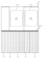
- FIG. 1 is an explanatory view showing an outline of a storage system according to an embodiment.
- the main body 30 of the box 3 which is an example of the “predetermined housing” is provided with a plurality of drive bays 31 for removably attaching the storage drives 1 and 2.
- the control box 3 is exemplified as a box in FIG. 1, the “predetermined case” also includes the expansion box 4 as described later with reference to FIG. 2.
- the box 3 is configured as a control box in charge of control of the storage system, and a plurality of (for example, two) controllers 32 are provided.
- Each controller 32 has a redundant configuration, and when one of the controllers 32 stops due to a failure or the like, the other controller 32 takes over the processing.
- Each controller 32 accesses the storage drives 1 and 2 corresponding to the logical volume to be accessed in accordance with access requests (read request and write request) from a computer (not shown), and reads / writes data.
- the standard storage drive 1 as a “standard storage drive” comprises, for example, a canister 10 and a substrate 11 as a “first substrate” mounted in the canister 10.
- the substrate 11 is formed to occupy approximately half of the longitudinal direction of the space defined by the canister 10. That is, since the substrate 11 is smaller than the canister 10, the unused space 15 is formed in the canister 10. More specifically, the substrate 11 is attached near the back side of the canister 10, and an unused space 15 is formed between the front side of the canister 10 and the substrate 11.
- a connector 12 for electrically connecting to the controller 32 is provided on the back of the canister 10.
- the bottom of the canister 10 is provided with a guide portion 13 for guiding the canister 10 into and out of the drive bay 31.
- a handle 14 is provided which is gripped by the user when the storage drive 1 is taken in and out of the drive bay 31.
- the front of the canister 10 indicates the front when the storage drive 1 is attached to the drive bay 31 of the box 3.
- the back surface of the canister 10 indicates the surface facing the front surface of the canister 10.
- the bottom surface of the canister 10 indicates the lower surface when the storage drive 1 is attached to the box 3.
- the surface facing the bottom surface of the canister 10 is the top surface.
- the other side is the side. Although illustration is omitted, air flows from the front of the canister 10 into the canister 10 to cool the internal circuit. The cooling air flows from the rear surface of the canister 10 to the outside.
- the flash memory 110 as the “first storage element” is configured as, for example, a NAND flash memory.
- the control circuit 111 controls data input / output to each flash memory 110 and the like.
- the cache memory 112 is configured as, for example, a dynamic random access memory (DRAM).
- DRAM dynamic random access memory
- the highly functional storage drive 2 as a “storage drive” includes, for example, a drive carrier 20 and a substrate 21 attached to the drive carrier 20.
- the drive carrier 20 as a "frame” is formed in, for example, a rectangular shape whose one end side is open like a U-shape which is turned over sideways.
- the substrate 21 is an example of the “second substrate”.
- the drive carrier 20 forms an available space 25 corresponding to the internal space of the canister 10.
- the substrate 21 is attached so as to fill substantially the entire available space 25.
- the available space 25 of the high-performance storage drive 2 is about twice as large as the unused space 15 of the standard storage drive 1. The doubling is an example and is not limited to this value.
- a connector 22 for electrically connecting to the controller 32 is provided on the back of the drive carrier 20.
- a guide portion 23 for guiding the drive carrier 20 into and out of the drive bay 31 is provided.
- a handle 24 is provided which is held by the user when the storage drive 2 is taken in and out of the drive bay 31.
- W1 ⁇ height H1 ⁇ depth D1) is set to be the same.
- either the standard storage drive 1 or the high performance storage drive 2 can be mounted in each drive bay 31. Therefore, the standard type storage drive 1 or the high performance type storage drive 2 can be mixed and mounted in the box 3.
- logical volumes including virtual volumes formed by virtualizing logical volumes are configured using physical storage areas of storage drives of the same type.
- the substrate 21 is configured by connecting a plurality of (two) sub substrates 21A and 21B by a flexible connection portion 21C, as described later with reference to FIG.
- the sub substrates 21A and 21B are configured as, for example, rigid substrates, and at least a part of the substrate side portions are electrically connected by the flexible connection portion 21C.
- the substrate 21 is attached to the drive carrier 20 by folding the two sub-substrates 21A and 21B in half at the connection portion 21C.
- a plurality of flash memories 210 On the surface of the substrate 21, a plurality of flash memories 210, a control circuit 211 which is a flash memory controller, a cache memory 212, and a battery circuit 213 are provided.
- the flash memory 210 as a "second memory element" is configured as, for example, a NAND flash memory.
- the number of mounted flash memories 210 is larger than the number of flash memories 110 mounted in the standard storage drive 1. This is because the mounting area of the substrate 21 is larger than the mounting area of the substrate 11.
- the size of the cache memory 212 configured as a DRAM is larger than the size of the cache memory 112 mounted on the standard storage drive 1.
- the control circuit 211 controls the data input / output to each flash memory 210 and, for example, implements a function of eliminating duplicate data, a function of compressing data, and a function of encrypting data.
- the control circuit 211 having the duplicate data elimination function, the data compression function, and the data encryption function is an example of the “predetermined circuit”.
- the control circuit 211 does not have to realize all the functions described above.
- the control circuit 211 may also realize functions other than the above-described functions.
- the high-performance type storage drive 2 exceeds both the number of mounted flash memories 210 and the memory size of the cache memory 212 as compared with the standard type storage drive 1, and the control circuit 211 is a standard type storage. It is more multifunctional than the control circuit 111 of the drive 1.
- control box 3 has main functions of the storage system such as a control function and a storage function in one case, and controls data input / output to each expansion box 4.
- the expansion box 4 has only the storage function and is controlled by the control box 3.
- the control box 3 can also be called a basic case, and the expansion box 4 can be called an additional case.
- the control box 3 is disposed at the lowermost stage of the rack 5, but the arrangement location of the control box 3 is not limited to the lowermost stage.
- FIG. 3 is a plan view of the control box 3 or the expansion box 4 as viewed from above.
- drive bays 31 (not shown in FIG. 3) are provided at predetermined intervals on the front side of the boxes 3 and 4, and each drive bay 31 is either a standard storage drive 1 or a high performance storage drive 2.
- the kimono is attached.
- the connector 12 of the standard storage drive 1 or the connector 22 of the advanced storage drive 2 is attached to the backboards 33 and 44 and electrically connected.
- the backboard 33 is a backboard of the control box 3
- the backboard 43 is a backboard of the expansion box 4.
- the backboards 33 and 43 are provided so as to separate the substantially central portions of the boxes 3 and 4.
- the processing substrates 32 and 42 are provided on the back side of the boxes 3 and 4.
- the processing substrate 32 is a processing substrate of the control box 3, and the processing substrate 42 is a processing substrate of the expansion box 4.
- the processing substrate 32 is electrically connected to the storage drives 1 and 2 via the backboard 33.
- the processing substrate 42 is electrically connected to the storage drives 1 and 2 via the backboard 43.
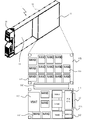
- FIG. 4 is a perspective view of the high performance type storage drive 2. Although FIG. 4 shows how the substrate 21 is attached to the drive carrier 20 in an exposed state, in reality, both side surfaces of the drive carrier 20 are detachably covered with a metal plate or the like (not shown).
- the first sub substrate 21A and the second sub substrate 21B have the flash memory 210 and the like mounted on both sides thereof. Only one side is shown in FIG.
- a battery circuit 213 located on the front side of the storage drive 1, a control circuit 211 and a cache memory 212 located on the back side of the storage drive 1, a battery circuit 213 and a control circuit 211 And a plurality of flash memories 210 located between them.
- a plurality of flash memories 210 are mounted on the second sub substrate 21B.
- the first sub substrate 21A and the second sub substrate 21B are electrically connected via the flexible connection portion 21C.
- the substrate 21 is folded in half and attached to the drive carrier 20 by bending the flexible connection portion 21C at approximately 180 degrees.
- the flexible connection portion 21C can be realized by attaching the flexible substrate to the connector for the flexible substrate mounted on each of the sub substrates 21A and 21B.
- the method of realizing the flexible connection portion 21C may be realized by a method other than the flexible substrate and the connector. There is no particular limitation in this embodiment.
- FIG. 5 is a perspective view of the standard storage drive 1.
- the canister 10 is indicated by a two-dot chain line, and the region in which the substrate 11 is disposed is indicated by a rectangular solid line.
- the substrate 11 includes a first sub substrate 11A, a second sub substrate 11B, and a flexible connection portion 11C that electrically connects the sub substrates 11A and 11B.
- a control circuit 111, a cache memory 112, a battery circuit 113, and a flash memory 110 are mounted on the first sub substrate 11A.
- the flash memory 110 is mounted on the second sub substrate 11B.
- the substrate 21 is disposed using almost all the space 25 in the drive carrier 20 having the same external dimensions as the canister 10.
- FIG. 6 is an explanatory view showing an example of the communication interface conversion board 16.
- the canister 10 of the standard storage drive 1 may be provided with a communication interface conversion substrate 16 in addition to the substrate 11.
- the communication interface conversion board 16 is disposed in the unused space 15.
- a connector 161 for Serial Attached SCSI (SAS) and a connector 162 for Non-Volatile Memory Host Controller Interface (NVMe) are shown.
- SAS Serial Attached SCSI
- NVMe Non-Volatile Memory Host Controller Interface
- FIG. 6 a plan view of the communication interface conversion board 16 for converting SAS and NVMe is shown. That is, the communication interface conversion board 16 connects the “SAS Port A” pin and the “SAS Port B” pin shown in FIG. 6 to “PCIe LANE 2”. By placing the communication interface conversion board 16 between the host and the device, the host can access the SAS device in the same manner as the NVMe device.
- a communication interface circuit that implements the same function as the communication interface conversion substrate 16 is mounted on the substrate 21.
- the communication interface circuit 21 may be provided in the control circuit 211.
- the type of communication interface can be specified based on the output state of the signal pin.
- FIG. 7 is a flowchart of processing for recognizing the type of storage drive and the type of communication interface. This process is executed by, for example, the processing substrate 32 of the control box 3. Hereinafter, the subject of the operation will be described as the control box 3.
- the control box 3 confirms the output state of the signal pin (S10), and determines whether the device interface standard is SAS or PCIe (NVMe) S11 (S11).
- the control box 3 When determining that the communication standard to be used is PCIe, the control box 3 reads out management information from the storage drive according to PCIe (S12). On the other hand, when the control box 3 determines that the communication standard to be used is SAS, the control box 3 reads out management information from the storage drive according to the SAS (S13). Among the storage areas of the storage drives 1 and 2, management information such as drive type, storage capacity, and vendor name are stored in the management area.
- control box 3 can determine the type of the storage drive by reading out the management information from the storage drive (S14). By previously determining the communication standard (type of communication interface) based on the output state of the signal pin, the management information can be read using the determined communication interface.
- the storage drive is a high performance type storage drive 2 using PCIe as a communication standard (S15), and the standard storage drive 1 using PCIe as a communication standard (S16), high performance It can be classified into four types: the type storage drive 2 that uses SAS as a communication standard (S17), and the standard type storage drive 1 that uses SAS as a communication standard (S18).
- FIG. 8 is a flowchart of processing to check whether the type of storage drive is unified in box units.
- the control box 3 acquires the determination result of the storage drive attached to each drive bay 31 of each box 3 and 4 (S20), and determines whether different types of storage drives are mixed in the same box (S21) .
- control box 3 determines that different types of storage drives are mixed in the same box (S21: YES), for example, "The drive type is not unified. For the storage system administrator. Drive bay A warning message such as “No. # 001 Drive type: Standard type (SAS)” is notified (S22).
- control box 3 is replaced by blinking or lighting LED lamps (not shown) provided in the vicinity of the drive bay 31 in which different types of storage drives are mounted among the drive bays 31 of the box 3 The user is notified of the mounting position of the storage drive to be used (S23).
- the high-performance type storage drive 2 having the same external dimensions as the standard type storage drive 1 can be provided, it can be mounted on the standard boxes 3 and 4 .
- the manufacturing cost of the boxes 3 and 4 and the storage system can be reduced.
- the external dimensions of the high performance type storage drive 2 are made common to the external dimensions of the standard type storage drive 1, and the handle portion 14 and the guide portion 13 are provided. Almost all the space 15 is also used. For this reason, in the present embodiment, it is possible to increase the mounting number of the flash memory 210 on the substrate 21 and mount the cache memory 212 having a larger memory size on the substrate 21. Furthermore, since the mounting area of the substrate 21 can be increased, the control circuit 211 can be made larger than the control circuit 111 of the standard storage drive 1 and various functions can be mounted. As described above, the high performance type storage drive 2 of the present embodiment can provide large storage capacity and high performance processing while having the same external dimensions as the standard type storage drive 1.
- the external dimensions of the standard storage drive 1 and the high-performance storage drive 2 are made common so that they can be attached to the boxes 3 and 4, so that different types of storage drives may be mixed in the box. is there.
- different types of storage drives may be mixed in the box. is there.
- the type of storage drive and the type of communication interface mounted in each drive bay 31 are determined, and only the storage drive of the same type (a storage drive having the same communication interface) is identical in the same box. It is monitored to be attached and notified of the monitoring result.
- the types of storage drives (including the type of communication interface) can be made uniform in box units, so that performance degradation of the storage system can be suppressed in advance, and reliability can be improved.
Landscapes
- Engineering & Computer Science (AREA)
- Theoretical Computer Science (AREA)
- Physics & Mathematics (AREA)
- General Engineering & Computer Science (AREA)
- General Physics & Mathematics (AREA)
- Human Computer Interaction (AREA)
- Mounting Of Printed Circuit Boards And The Like (AREA)
Abstract
Description
本発明は、記憶ドライブおよびストレージシステムに関する。 The present invention relates to storage drives and storage systems.
標準のフォームファクタを有する記憶装置をドライブベイに装着する場合、記憶装置よりも大きなキャニスタ内に記憶装置を収容し、そのキャニスタをドライブベイへ取り付ける(特許文献1,2)。あるいは、標準のフォームファクタとは異なるベンダ固有のフォームファクタを採用し、独自仕様の記憶ドライブおよびドライブを収容するボックスを製造することも知られている。
When a storage device having a standard form factor is mounted in a drive bay, the storage device is accommodated in a canister larger than the storage device, and the canister is attached to the drive bay (
独自仕様の記憶ドライブおよびボックスを製造する場合は、機能や性能で競合他社との差別化を図りやすいが、開発の手間がかかり、製造コストも増大する。一方、標準の記憶装置と標準のドライブボックスを用いる場合、記憶容量や機能等の点で競合他社と差別化するのは難しい。 When manufacturing proprietary storage drives and boxes, it is easy to differentiate from competitors in terms of functions and performance, but it takes time for development and increases manufacturing costs. On the other hand, when using a standard storage device and a standard drive box, it is difficult to differentiate from competitors in terms of storage capacity and functions.
本発明は、上記問題に鑑みてなされたもので、その目的は、コスト低減と性能および機能の増大とを両立できるようにした記憶ドライブおよびストレージシステムを提供することにある。本発明のさらなる目的は、標準の記憶ドライブと同一の外形寸法を持つと共に、標準の記憶ドライブでは利用されていなかった空間も利用することのできる記憶ドライブおよびストレージシステムを提供することにある。 The present invention has been made in view of the above problems, and an object thereof is to provide a storage drive and a storage system in which cost reduction and increase in performance and functions can be compatible. A further object of the present invention is to provide a storage drive and storage system which has the same external dimensions as a standard storage drive, and can also utilize the space that was not used in the standard storage drive.
上記課題を解決すべく、本発明に従う記憶ドライブは、第1記憶素子の実装された第1基板よりも大きなキャニスタを有する標準の記憶ドライブと同一の外形寸法を持つ記憶ドライブであって、キャニスタ内の空間に対応する利用可能空間を形成するフレームと、利用可能空間の全体を使用するようにフレームに設けられた第2基板と、第2基板の全体に実装された第2記憶素子および所定の回路と、フレームに設けられ、記憶ドライブを着脱可能に収容する所定の筐体へフレームを取り付けるためのガイド部と、を備える。 In order to solve the above problems, a storage drive according to the present invention is a storage drive having the same external dimensions as a standard storage drive having a canister larger than a first substrate on which a first storage element is mounted. A frame forming an available space corresponding to the space, a second substrate provided on the frame so as to use the entire available space, a second storage element mounted on the entire second substrate, and a predetermined A circuit, and a guide portion provided on the frame and for attaching the frame to a predetermined housing that detachably accommodates the storage drive.
本発明によれば、標準の記憶ドライブと同一の外形寸法を持ち、利用可能空間の全体を使用するようにフレームに設けられた第2基板板の全体に実装された第2記憶素子および所定の回路と、所定の筐体へフレームを取り付けるためのガイド部とを備える記憶ドライブを得ることができる。 According to the present invention, the second storage element mounted on the entire second board provided on the frame and having the same external dimensions as a standard storage drive and using the entire available space, and a predetermined storage element It is possible to obtain a storage drive provided with a circuit and a guide for attaching the frame to a predetermined housing.
以下、図面に基づいて、本発明の実施の形態を説明する。本実施形態では、所定の筐体に着脱できるように標準の記憶ドライブと同一の外形寸法を有し、かつ、ベンダ固有の性能および機能を有する記憶ドライブを提供する。 Hereinafter, embodiments of the present invention will be described based on the drawings. The present embodiment provides a storage drive having the same external dimensions as a standard storage drive so as to be attachable to and detachable from a predetermined housing, and having vendor-specific performance and functions.
これにより本実施形態に係る記憶ドライブによれば、標準の記憶ドライブと同様に所定の筐体に着脱することができると共に、標準の記憶ドライブでは活用されていなかった空間を有効利用することにより大容量化および機能改善を実現することができる。 Thus, according to the storage drive according to the present embodiment, the storage drive can be attached to and detached from a predetermined housing as well as a standard storage drive, and a large space can be obtained by effectively using the space not used in the standard storage drive. Capacitance and function improvement can be realized.
以下、図面に従い、本実施形態の一例を説明する。図1は、実施例に係るストレージシステムの概要を示す説明図である。 Hereinafter, an example of the present embodiment will be described with reference to the drawings. FIG. 1 is an explanatory view showing an outline of a storage system according to an embodiment.
「所定の筐体」の一例であるボックス3の本体30には、記憶ドライブ1,2を着脱可能に取り付けるための複数のドライブベイ31が設けられている。図1では、ボックスとしてコントロールボックス3を例に挙げるが、図2で後述するように、「所定の筐体」には拡張ボックス4も含まれる。
The
ボックス3は、ストレージシステムの制御を担当するコントロールボックスとして構成されており、複数の(例えば2つの)コントローラ32が設けられている。各コントローラ32は、冗長構成となっており、いずれか一方のコントローラ32が障害等で停止した場合、他方のコントローラ32が処理を引き継ぐ。各コントローラ32は、図外の計算機からのアクセス要求(リード要求、ライト要求)にしたがって、アクセス対象の論理ボリュームに対応する記憶ドライブ1,2にアクセスし、データを読み書きする。
The
「標準の記憶ドライブ」としての標準型記憶ドライブ1は、例えば、キャニスタ10と、キャニスタ10内に取り付けられた「第1基板」としての基板11とを備える。基板11は、キャニスタ10により画成される空間の長手方向の半分程度を占めるように形成されている。つまり、基板11は、キャニスタ10よりも小さいため、キャニスタ10内には未利用空間15が形成されている。より詳しくは、基板11は、キャニスタ10の背面側寄りに取り付けられており、キャニスタ10の前面側と基板11との間には未利用空間15が形成されている。
The
キャニスタ10の背面には、コントローラ32と電気的に接続するためのコネクタ12が設けられている。キャニスタ10の底面には、ドライブベイ31にキャニスタ10を出し入れする際にガイドするガイド部13が設けられている。キャニスタ10の前面には、ドライブベイ31に記憶ドライブ1を出し入れする際にユーザにより把持される取っ手部14が設けられている。
A
キャニスタ10の前面とは、記憶ドライブ1をボックス3のドライブベイ31へ装着した場合の正面を示す。キャニスタ10の背面とは、キャニスタ10の前面に対向する面を示す。キャニスタ10の底面とは、記憶ドライブ1をボックス3に装着した場合の下側の面を示す。なお、キャニスタ10の底面に対向する面は上面である。その他の面は、側面である。図示は省略するが、キャニスタ10の前面から空気がキャニスタ10内に流入し、内部の回路を空冷する。冷却風は、キャニスタ10の背面等から外部に流出する。
The front of the
基板11には、複数のフラッシュメモリ110と、コントロール回路111と、キャッシュメモリ112と、バッテリ回路113とが設けられている。「第1記憶素子」としてのフラッシュメモリ110は、例えばNAND型フラッシュメモリとして構成される。コントロール回路111は、各フラッシュメモリ110へのデータ入出力等を制御する。キャッシュメモリ112は、例えば、DRAM(Dynamic Random Access Memory)として構成される。
On the
「記憶ドライブ」としての高機能型記憶ドライブ2は、例えば、ドライブキャリア20と、ドライブキャリア20に取り付けられた基板21とを備える。「フレーム」としてのドライブキャリア20は、例えば横倒しにしたU字状のように、一端側が開放された矩形状に形成されている。基板21は「第2基板」の例である。
The highly
ドライブキャリア20は、キャニスタ10の内部空間に対応する利用可能空間25を形成する。この利用可能空間25のほぼ全体を埋めるようにして、基板21が取り付けられている。記憶ドライブ1,2を側面から見た場合、高機能型記憶ドライブ2の利用可能空間25は、標準型記憶ドライブ1の未利用空間15の約2倍の大きさである。2倍とは例示であって、この数値に限定されない。
The
ドライブキャリア20の背面には、コントローラ32と電気的に接続するためのコネクタ22が設けられている。ドライブキャリア20の底面には、ドライブベイ31にドライブキャリア20を出し入れする際にガイドするガイド部23が設けられている。ドライブキャリア20の前面には、ドライブベイ31に記憶ドライブ2を出し入れする際にユーザにより把持される取っ手部24が設けられている。
A
ここで、各ドライブベイ31へ着脱可能に取り付けることができるように、標準型記憶ドライブ1の外形寸法(幅W1×高さH1×奥行きD1)と、高機能型記憶ドライブ2の外形寸法(幅W1×高さH1×奥行きD1)とは、同一に設定されている。
Here, the external dimensions (width W1 × height H1 × depth D1) of the
すなわち、各ドライブベイ31には、標準型記憶ドライブ1または高機能型記憶ドライブ2のいずれか一方を装着することができる。したがって、ボックス3には、標準型記憶ドライブ1または高機能型記憶ドライブ2を混在させて搭載することができる。
That is, either the
しかし、物理的記憶装置である記憶ドライブの物理的記憶領域を仮想化することにより形成される論理ボリュームでは、種類の異なる記憶ドライブの物理的記憶領域が混在するのは、性能上好ましくない。したがって、論理ボリューム(論理ボリュームを仮想化して形成される仮想ボリュームも含む)は、同一種類の記憶ドライブの物理的記憶領域を用いて構成されるようになっている。 However, in a logical volume formed by virtualizing a physical storage area of a storage drive which is a physical storage device, it is not preferable in terms of performance that physical storage areas of different types of storage drives are mixed. Accordingly, logical volumes (including virtual volumes formed by virtualizing logical volumes) are configured using physical storage areas of storage drives of the same type.
コントロールボックス3または拡張ボックス4のボックス単位で記憶ドライブの種類を統一する場合、各ボックス内には同一種類の記憶ドライブが装着されることになる。しかし、標準型記憶ドライブ1および高機能型記憶ドライブ2は、ドライブベイ31へ装着可能なように同一の外形寸法をもって形成されているため、人為的ミスにより一つのボックス内に種類の異なる記憶ドライブ1,2が混在する可能性もある。この人為的ミスの発生を抑止するための構成は、図7および図8で後述する。
When the types of storage drives are unified in box units of the
基板21は、図4で後述するように、複数の(2つの)サブ基板21A,21Bをフレキシブル接続部21Cで接続することにより構成される。サブ基板21A,21Bは、例えばリジット基板として構成されており、基板側部の少なくとも一部がフレキシブル接続部21Cによって電気的に接続されている。そして、基板21は、2つのサブ基板21A,21Bを接続部21Cで二つ折りにすることにより、ドライブキャリア20に取り付けられる。
The
基板21の表面には、複数のフラッシュメモリ210と、フラッシュメモリコントローラであるコントロール回路211と、キャッシュメモリ212と、バッテリ回路213とが設けられている。「第2記憶素子」としてのフラッシュメモリ210は、例えばNAND型フラッシュメモリとして構成されている。フラッシュメモリ210の搭載数は、標準型記憶ドライブ1に搭載されるフラッシュメモリ110の数よりも多い。基板21の実装面積が基板11の実装面積よりも大きいためである。また、DRAMとして構成されるキャッシュメモリ212のサイズは、標準型記憶ドライブ1に搭載されるキャッシュメモリ112のサイズよりも大きい。
On the surface of the
コントロール回路211は、各フラッシュメモリ210へのデータ入出力を制御するほかに、例えば、重複したデータを排除する機能、データを圧縮する機能、データを暗号化する機能を実現する。これら重複データ排除機能、データ圧縮機能、データ暗号化機能を有するコントロール回路211は「所定の回路」の例である。コントロール回路211は、上述した機能を全て実現する必要はない。また、コントロール回路211は、上述した機能以外の機能を実現してもよい。
The
このように、高機能型記憶ドライブ2は、標準型記憶ドライブ1と比べると、フラッシュメモリ210の搭載数およびキャッシュメモリ212のメモリサイズのいずれも上回っており、かつ、コントロール回路211は標準型記憶ドライブ1のコントロール回路111よりも多機能である。
Thus, the high-performance
図2を参照する。図2に示すように、ラック5内には、一つのコントロールボックス3と複数の拡張ボックス4とが着脱可能に収容されている。コントロールボックス3は、制御機能および記憶機能などのストレージシステムの主要機能を一つの筐体内に備えており、各拡張ボックス4へのデータ入出力を制御する。これに対し、拡張ボックス4は、記憶機能のみを備えており、コントロールボックス3により制御される。コントロールボックス3は基本筐体と、拡張ボックス4は増設筐体と、それぞれ呼ぶこともできる。なお、図2では、ラック5の最下段にコントロールボックス3を配置しているが、コントロールボックス3の配置場所は最下段に限らない。
Please refer to FIG. As shown in FIG. 2, in the
図3は、コントロールボックス3または拡張ボックス4を上から見た平面図である。例えば、ボックス3,4の前面側にはドライブベイ31(図3では図示省略)が所定間隔で設けられており、各ドライブベイ31には標準型記憶ドライブ1または高機能型記憶ドライブ2のいずれかが装着されている。
FIG. 3 is a plan view of the
標準型記憶ドライブ1のコネクタ12または高機能型記憶ドライブ2のコネクタ22は、バックボード33,44に取り付けられて、電気的に接続される。バックボード33はコントロールボックス3のバックボードであり、バックボード43は拡張ボックス4のバックボードである。バックボード33,43は、ボックス3,4の略中央部を区切るようにして設けられている。
The
ボックス3,4の背面側には、処理基板32,42が設けられている。処理基板32はコントロールボックス3の処理基板であり、処理基板42は拡張ボックス4の処理基板である。処理基板32はバックボード33を介して各記憶ドライブ1,2に電気的に接続されている。同様に処理基板42はバックボード43を介して各記憶ドライブ1,2に電気的に接続されている。
The processing substrates 32 and 42 are provided on the back side of the
図4は、高機能型記憶ドライブ2の斜視図である。図4では、ドライブキャリア20に基板21を露出状態で装着する様子を示すが、実際には、ドライブキャリア20の両側面は図示せぬ金属板等により着脱可能に覆われている。
FIG. 4 is a perspective view of the high performance
第1サブ基板21A,第2サブ基板21Bは、それぞれの両面にフラッシュメモリ210等が実装される。図4では、片側の面だけを示している。
The
第1サブ基板21Aには、例えば、記憶ドライブ1の前面側に位置するバッテリ回路213と、記憶ドライブ1の背面側に位置するコントロール回路211およびキャッシュメモリ212と、バッテリ回路213とコントロール回路211との間に位置する複数のフラッシュメモリ210とが搭載されている。
In the
第2サブ基板21Bには、複数のフラッシュメモリ210が搭載されている。そして、第1サブ基板21Aと第2サブ基板21Bとは、フレキシブル接続部21Cを介して電気的に接続されている。フレキシブル接続部21Cを略180度に折り曲げることにより、基板21は二つ折り状態にされて、ドライブキャリア20に取り付けられる。
A plurality of
ここで、例えば、各サブ基板21A,21Bにそれぞれ実装したフレキシブル基板用のコネクタにフレキシブル基板を取り付けることにより、フレキシブル接続部21Cを実現することができる。フレキシブル接続部21Cの実現方法は、フレキシブル基板およびコネクタ以外の方法で実現してもよい。本実施形態では特に問わない。
Here, for example, the
図5は、標準型記憶ドライブ1の斜視図である。キャニスタ10を二点鎖線で示し、基板11の配置される領域を矩形状の実線で示す。
FIG. 5 is a perspective view of the
基板11は、第1サブ基板11Aと、第2サブ基板11Bと、各サブ基板11A,11Bを電気的に接続するフレキシブル接続部11Cとを備える。
The
第1サブ基板11Aには、コントロール回路111と、キャッシュメモリ112と、バッテリ回路113と、フラッシュメモリ110が搭載されている。第2サブ基板11Bには、フラッシュメモリ110が搭載されている。
A
図4と図5を比較するとわかるように、図5に示す標準型記憶ドライブ1では、キャニスタ10内の空間のうち略半分の空間が基板11の配設空間として利用されているに過ぎず、比較的大きな未利用空間15がキャニスタ10内に残されている。
As can be seen by comparing FIG. 4 and FIG. 5, in the
これに対し、図4に示す高機能型記憶ドライブ2では、キャニスタ10と同一の外形寸法を持つドライブキャリア20内の空間25をほぼ全て利用して、基板21が配設されている。
On the other hand, in the high performance
図6は、通信インターフェース変換基板16の例を示す説明図である。標準型記憶ドライブ1のキャニスタ10には、基板11のほかに通信インターフェース変換基板16を設けてもよい。通信インターフェース変換基板16は、未利用空間15に配置される。
FIG. 6 is an explanatory view showing an example of the communication
図6の左上には、SAS(Serial Attached SCSI)用のコネクタ161と、NVMe(Non-Volatile Memory Host Controller Interface)用のコネクタ162とが示されている。図6の右上には、SASとNVMeを変換する通信インターフェース変換基板16の平面図が示されている。すなわち、通信インターフェース変換基板16は、図6中に示す”SAS Port A”のピンと ”SAS Port B”のピンとを”PCIe LANE2”に接続する。この通信インターフェース変換基板16を、ホストとデバイスの間に置くことにより、ホストはSASデバイスをNVMeデバイスと同様にアクセスすることができる。
At the upper left of FIG. 6, a
高機能型記憶ドライブ2では、通信インターフェース変換基板16と同様の機能を実現する通信インターフェース回路が基板21に搭載される。その通信インターフェース回路21は、コントロール回路211内に設けられてもよい。
In the high-performance
各信号ピンの位置と役割とは、コントロールボックス3の処理基板32にとって既知であるため、信号ピンの出力状態に基づいて、通信インターフェースの種類を特定することができる。
Since the position and role of each signal pin are known to the
図7は、記憶ドライブの種類と通信インターフェースの種類とを認識する処理のフローチャートである。本処理は、例えば、コントロールボックス3の処理基板32により実行される。以下では、動作の主体をコントロールボックス3として述べる。
FIG. 7 is a flowchart of processing for recognizing the type of storage drive and the type of communication interface. This process is executed by, for example, the
コントロールボックス3は、信号ピンの出力状態を確認し(S10)、デバイスインターフェースの規格がSASまたはPCIe(NVMe)のいずれであるか判別するS11(S11)。
The
コントロールボックス3は、使用する通信規格がPCIeであると判別すると、PCIeにしたがって記憶ドライブから管理情報を読み出す(S12)。これに対し、コントロールボックス3は、使用する通信規格がSASであると判別すると、SASにしたがって記憶ドライブから管理情報を読み出す(S13)。記憶ドライブ1,2の持つ記憶領域のうち管理領域には、例えば、ドライブ種別、記憶容量、ベンダ名等の管理情報が格納されている。
When determining that the communication standard to be used is PCIe, the
したがって、コントロールボックス3は、記憶ドライブから管理情報を読み出すことにより、その記憶ドライブの種別を判別することができる(S14)。通信規格(通信インターフェースの種類)を信号ピンの出力状態に基づいて先に判定することにより、判定した通信インターフェースを用いて管理情報を読み出すことができる。
Therefore, the
本実施例において、記憶ドライブは、高機能型記憶ドライブ2であって通信規格にPCIeを用いるもの(S15)、標準型記憶ドライブ1であって通信規格にPCIeを用いるもの(S16)、高機能型記憶ドライブ2であって通信規格にSASを用いるもの(S17)、標準型記憶ドライブ1であって通信規格にSASを用いるもの(S18)の4つのタイプに分類することができる。
In the present embodiment, the storage drive is a high performance
図8は、ボックス単位で記憶ドライブの種類が統一されているか検査する処理のフローチャートである。 FIG. 8 is a flowchart of processing to check whether the type of storage drive is unified in box units.
コントロールボックス3は、各ボックス3,4の各ドライブベイ31に装着された記憶ドライブの判別結果を取得し(S20)、同一ボックス内に異なる種類の記憶ドライブが混在しているか判定する(S21)。
The
コントロールボックス3は、異なる種類の記憶ドライブが同一ボックス内に混在していると判定すると(S21:YES)、例えばストレージシステムの管理者に対して、「ドライブ種類が統一されていません。ドライブベイ番号#001 ドライブ種別:標準型(SAS)」のような警告メッセージを通知する(S22)。
If the
さらに、コントロールボックス3は、ボックス3の各ドライブベイ31のうち異なる種類の記憶ドライブが装着されているドライブベイ31の近傍に設けられたLEDランプ(不図示)を点滅または点灯させることにより、交換すべき記憶ドライブの装着位置をユーザへ通知する(S23)。
Furthermore, the
このように構成される本実施例によれば、標準型記憶ドライブ1と同一外形寸法を持つ高機能型記憶ドライブ2を提供することができるため、標準のボックス3,4に装着することができる。この結果、本実施例によれば、ボックス3,4およびストレージシステムの製造コストを低減することができる。
According to the embodiment configured as described above, since the high-performance
本実施例では、高機能型記憶ドライブ2の外形寸法を標準型記憶ドライブ1の外形寸法と共通にすると共に、取っ手部14やガイド部13を設け、さらに標準型記憶ドライブ1では利用されていなかった空間15もほぼ全て利用する。このため、本実施例では、基板21へのフラッシュメモリ210の搭載数量を増加したり、よりメモリサイズの大きいキャッシュメモリ212を基板21へ搭載したりすることができる。さらに、基板21の実装面積を大きくできるため、コントロール回路211を標準型記憶ドライブ1のコントロール回路111よりも大型化して、種々の機能を実装することができる。このように本実施例の高機能型記憶ドライブ2は、標準型記憶ドライブ1と同一の外形寸法でありながら、大きな記憶容量と高機能処理とを提供することができる。
In the present embodiment, the external dimensions of the high performance
さらに本実施例では、ボックス3,4に装着できるように、標準型記憶ドライブ1と高機能型記憶ドライブ2の外形寸法を共通にしたため、ボックス内で異なる種類の記憶ドライブが混在する可能性がある。しかし、ボックス単位で論理ボリューム(または仮想ボリューム)へ物理的記憶領域を提供する場合、異なる種類の記憶ドライブが混在していると期待した通りの性能を得られない。
Furthermore, in the present embodiment, the external dimensions of the
そこで、本実施例では、各ドライブベイ31に装着された記憶ドライブの種類および通信インターフェースの種類を判別し、同一ボックス内には同一種類の記憶ドライブ(通信インターフェースも同じである記憶ドライブ)だけが装着されるように監視し、監視結果を通知するようにしている。これにより、本実施例では、ボックス単位で記憶ドライブ(通信インターフェースの種類も含む)の種類を揃えることができ、ストレージシステムの性能低下を未然に抑制することができ、信頼性が向上する。
Therefore, in the present embodiment, the type of storage drive and the type of communication interface mounted in each
なお、本発明は、上述した実施の形態に限定されない。当業者であれば、本発明の範囲内で、種々の追加や変更等を行うことができる。さらに、特許請求の範囲に記載した特徴は、特許請求の範囲に示す関係以外でも従属させることができる。 The present invention is not limited to the embodiments described above. Those skilled in the art can make various additions and modifications within the scope of the present invention. Further, the features recited in the claims can be subordinated to other than that indicated in the claims.
1:標準型記憶ドライブ、2:高機能型記憶ドライブ、3:コントロールボックス、4:拡張ボックス、5:ラック、10:キャニスタ、11:基板、20:ドライブキャリア、21:基板、31:ドライブベイ、110:フラッシュメモリ、111:コントロール回路、112:キャッシュメモリ、210:フラッシュメモリ、211:コントロール回路、212:キャッシュメモリ 1: Standard storage drive 2: High performance storage drive 3: Control box 4: Expansion box 5: Rack 10: Canister 11: board 20: drive carrier 21: board 31: drive bay , 110: flash memory, 111: control circuit, 112: cache memory, 210: flash memory, 211: control circuit, 212: cache memory
Claims (14)
前記キャニスタ内の空間に対応する利用可能空間を形成するフレームと、
前記利用可能空間の全体を使用するように前記フレームに設けられた第2基板と、
前記第2基板の全体に実装された第2記憶素子および所定の回路と、
前記フレームに設けられ、記憶ドライブを着脱可能に収容する所定の筐体へ前記フレームを取り付けるためのガイド部と、
を備える記憶ドライブ。 A storage drive having the same external dimensions as a standard storage drive having a canister larger than a first substrate on which a first storage element is mounted,
A frame forming an available space corresponding to the space in the canister;
A second substrate provided on the frame to use the entire available space;
A second memory element and a predetermined circuit mounted on the entire second substrate;
A guide portion provided on the frame and for attaching the frame to a predetermined housing which detachably accommodates a storage drive;
Storage drive comprising:
請求項1に記載の記憶ドライブ。 The predetermined circuit includes a communication function for communicating with another device, an overlapping data exclusion function for excluding overlapping data from the second storage element, a compression function for compressing data and storing the data in the second storage element, and data Among the encryption functions to be encrypted and stored in the second storage element, a circuit that implements at least one of the functions is included.
A storage drive according to claim 1.
前記コントローラにより、前記通信インターフェース回路の信号出力状態に基づいて前記記憶ドライブの通信インターフェースが特定される、
請求項2に記載の記憶ドライブ。 When the control box provided with a controller for controlling a storage drive is the predetermined housing, the predetermined circuit has a communication interface circuit for realizing at least the communication function,
The controller identifies the communication interface of the storage drive based on a signal output state of the communication interface circuit.
A storage drive according to claim 2.
請求項3に記載の記憶ドライブ。 The communication interface of the storage drive is specified by detecting, as the signal output state, an output terminal to which a signal is output among a plurality of output terminals of the communication interface circuit by the controller.
A storage drive according to claim 3.
請求項3に記載の記憶ドライブ。 The type of storage drive is specified by the controller reading predetermined management information from the storage element using the specified communication interface.
A storage drive according to claim 3.
請求項1に記載の記憶ドライブ。 The predetermined housing is a drive box that accommodates a storage drive.
A storage drive according to claim 1.
請求項1に記載の記憶ドライブ。 Can coexist with the standard storage drive in the predetermined housing
A storage drive according to claim 1.
前記2つのサブ基板のうち第1サブ基板には、前記第2記憶素子が実装され、
前記2つのサブ基板のうち第2サブ基板には、他の前記第2記憶素子と前記所定の回路とが実装される、
請求項1に記載の記憶ドライブ。 The second substrate is formed by connecting two sub substrates in a foldable manner,
The second storage element is mounted on a first sub substrate of the two sub substrates,
The other second storage element and the predetermined circuit are mounted on a second sub substrate of the two sub substrates.
A storage drive according to claim 1.
各記憶ドライブを制御するコントローラを有するコントロールボックスを備え、
前記各記憶ドライブには、第1記憶素子の実装された第1基板よりも大きなキャニスタを有する標準の記憶ドライブと、前記標準の記憶ドライブと同一の外形寸法を有する所定の記憶ドライブとが含まれており、
前記コントロールボックスには、前記標準の記憶ドライブと前記所定の記憶ドライブとを混在させて設けることができ、
前記所定の記憶ドライブは、
前記キャニスタと同一の外形寸法を有するフレームと、
前記フレームの形成する利用可能空間であって、前記キャニスタ内の空間に対応する利用可能空間の全体を使用するようにして、前記フレームに設けられる第2基板と、
前記第2基板に実装される第2記憶素子および所定の回路と、
前記フレームに設けられ、前記コントロールボックスに着脱可能に取り付けるためのガイド部と、
を備える、
ストレージシステム。 A storage system comprising a plurality of storage drives,
It has a control box with a controller that controls each storage drive,
Each of the storage drives includes a standard storage drive having a canister larger than the first substrate on which the first storage element is mounted, and a predetermined storage drive having the same external dimensions as the standard storage drive. Yes,
In the control box, the standard storage drive and the predetermined storage drive can be mixedly provided.
The predetermined storage drive is
A frame having the same external dimensions as the canister;
A second substrate provided on the frame so as to use the entire available space corresponding to the space in the canister, which is an available space formed by the frame;
A second memory element mounted on the second substrate and a predetermined circuit;
A guide portion provided on the frame for detachably attaching to the control box;
Equipped with
Storage system.
請求項9に記載のストレージシステム。 The predetermined circuit includes a communication function for communicating with another device, an overlapping data exclusion function for excluding overlapping data from the second storage element, a compression function for compressing data and storing the data in the second storage element, and data Among the encryption functions to be encrypted and stored in the second storage element, a circuit that implements at least one of the functions is included.
The storage system according to claim 9.
前記コントロールボックスに設けられる前記所定の記憶ドライブでは、前記第2基板上に第2通信インターフェース変換回路が設けられる、
請求項9に記載のストレージシステム。 In the standard storage drive provided in the control box, a first communication interface conversion circuit is provided in a space between the first substrate and the canister.
In the predetermined storage drive provided in the control box, a second communication interface conversion circuit is provided on the second substrate,
The storage system according to claim 9.
請求項11に記載のストレージシステム。 The controller specifies the communication interface of the standard storage drive or the communication interface of the predetermined storage drive based on the signal output state of the first communication interface conversion circuit or the signal output state of the second communication interface conversion circuit. Do,
A storage system according to claim 11.
前記コントロールボックスは、当該コントロールボックス内の記憶ドライブと前記ドライブボックス内の記憶ドライブとの両方を制御し、
前記ガイド部は、前記フレームを前記ドライブボックスに着脱可能に取り付ける、
請求項9に記載のストレージシステム。 A drive box in which the standard storage drive and the predetermined storage drive can be provided in combination, further comprising a drive box connected to the control box,
The control box controls both the storage drive in the control box and the storage drive in the drive box,
The guide unit detachably attaches the frame to the drive box.
The storage system according to claim 9.
請求項13に記載のストレージシステム。 The controller outputs a message when the storage drive in the control box or the type of storage drive in the drive box is not unified for each box.
The storage system according to claim 13.
Priority Applications (1)
| Application Number | Priority Date | Filing Date | Title |
|---|---|---|---|
| PCT/JP2017/042723 WO2019106736A1 (en) | 2017-11-29 | 2017-11-29 | Storage drive and storage system |
Applications Claiming Priority (1)
| Application Number | Priority Date | Filing Date | Title |
|---|---|---|---|
| PCT/JP2017/042723 WO2019106736A1 (en) | 2017-11-29 | 2017-11-29 | Storage drive and storage system |
Publications (1)
| Publication Number | Publication Date |
|---|---|
| WO2019106736A1 true WO2019106736A1 (en) | 2019-06-06 |
Family
ID=66665470
Family Applications (1)
| Application Number | Title | Priority Date | Filing Date |
|---|---|---|---|
| PCT/JP2017/042723 Ceased WO2019106736A1 (en) | 2017-11-29 | 2017-11-29 | Storage drive and storage system |
Country Status (1)
| Country | Link |
|---|---|
| WO (1) | WO2019106736A1 (en) |
Citations (5)
| Publication number | Priority date | Publication date | Assignee | Title |
|---|---|---|---|---|
| JPH0689131A (en) * | 1992-09-08 | 1994-03-29 | Seiko Epson Corp | Personal computer |
| JP2001282703A (en) * | 2000-03-31 | 2001-10-12 | Hitachi Ltd | Information processing device with device exchange function |
| JP2003108262A (en) * | 2001-09-28 | 2003-04-11 | Toshiba Corp | Card-shaped electronic devices |
| JP2005174119A (en) * | 2003-12-12 | 2005-06-30 | Ricoh Co Ltd | Image data control apparatus, image forming apparatus, and image data control method |
| JP2012064763A (en) * | 2010-09-16 | 2012-03-29 | Nec Corp | Printed circuit board fixing device |
-
2017
- 2017-11-29 WO PCT/JP2017/042723 patent/WO2019106736A1/en not_active Ceased
Patent Citations (5)
| Publication number | Priority date | Publication date | Assignee | Title |
|---|---|---|---|---|
| JPH0689131A (en) * | 1992-09-08 | 1994-03-29 | Seiko Epson Corp | Personal computer |
| JP2001282703A (en) * | 2000-03-31 | 2001-10-12 | Hitachi Ltd | Information processing device with device exchange function |
| JP2003108262A (en) * | 2001-09-28 | 2003-04-11 | Toshiba Corp | Card-shaped electronic devices |
| JP2005174119A (en) * | 2003-12-12 | 2005-06-30 | Ricoh Co Ltd | Image data control apparatus, image forming apparatus, and image data control method |
| JP2012064763A (en) * | 2010-09-16 | 2012-03-29 | Nec Corp | Printed circuit board fixing device |
Similar Documents
| Publication | Publication Date | Title |
|---|---|---|
| US8393907B2 (en) | Storage apparatus and method of manufacturing the same | |
| JP4438846B2 (en) | Card type peripheral device | |
| US20130208542A1 (en) | Embedded solid state disk as a controller of a solid state disk | |
| US20150362965A1 (en) | Carrier with Multiple Storage Devices Having Different Form Factors | |
| US10956326B2 (en) | Storage system with data management and protection mechanism and method of operation thereof | |
| TW201603026A (en) | Solid-state memory device with plurality of memory cards | |
| US10579302B2 (en) | Semiconductor device | |
| CN114079197A (en) | Expansion kit, storage device assembly and storage device | |
| JP2017531856A (en) | Active storage units and arrays | |
| US10320105B2 (en) | Printed circuit boards and solid state drives including the same | |
| US20160254031A1 (en) | Semiconductor memory device | |
| US8626985B2 (en) | Hybrid optical disk drive, method of operating the same, and electronic system adopting the hybrid optical disk drive | |
| JP2017027540A (en) | Semiconductor device and electronic equipment | |
| CN103019998A (en) | Upgradeable solid hard disk capacity expanding device | |
| WO2019106736A1 (en) | Storage drive and storage system | |
| US20210303047A1 (en) | Dual-Connector Storage System and Method for Simultaneously Providing Power and Memory Access to a Computing Device | |
| KR20220048559A (en) | Storage device, latch assembly and storage assembly comprising the same | |
| US20240419932A1 (en) | Storage device | |
| US20250220829A1 (en) | Extension storage modules for changing form factor of storage devices, and storage devices including the same | |
| US9208068B2 (en) | Data storage devices including multiple host interfaces and user devices including the same | |
| EP4650911A1 (en) | Storage device, electronic device including the same, and operating method of the electronic device | |
| US20250159811A1 (en) | Semiconductor storage device | |
| US7418646B2 (en) | Integrated circuit using wireless communication to store and/or retrieve data and/or check data | |
| JP2010061438A (en) | Information processor | |
| US20070066119A1 (en) | Memory device with serial AT attachment |
Legal Events
| Date | Code | Title | Description |
|---|---|---|---|
| 121 | Ep: the epo has been informed by wipo that ep was designated in this application |
Ref document number: 17933260 Country of ref document: EP Kind code of ref document: A1 |
|
| NENP | Non-entry into the national phase |
Ref country code: DE |
|
| 122 | Ep: pct application non-entry in european phase |
Ref document number: 17933260 Country of ref document: EP Kind code of ref document: A1 |
|
| NENP | Non-entry into the national phase |
Ref country code: JP |