WO2019044072A1 - Information display device - Google Patents
Information display device Download PDFInfo
- Publication number
- WO2019044072A1 WO2019044072A1 PCT/JP2018/020215 JP2018020215W WO2019044072A1 WO 2019044072 A1 WO2019044072 A1 WO 2019044072A1 JP 2018020215 W JP2018020215 W JP 2018020215W WO 2019044072 A1 WO2019044072 A1 WO 2019044072A1
- Authority
- WO
- WIPO (PCT)
- Prior art keywords
- light
- display device
- information display
- image
- polarized wave
- Prior art date
- Legal status (The legal status is an assumption and is not a legal conclusion. Google has not performed a legal analysis and makes no representation as to the accuracy of the status listed.)
- Ceased
Links
Images


Classifications
-
- G—PHYSICS
- G02—OPTICS
- G02B—OPTICAL ELEMENTS, SYSTEMS OR APPARATUS
- G02B27/00—Optical systems or apparatus not provided for by any of the groups G02B1/00 - G02B26/00, G02B30/00
- G02B27/01—Head-up displays
- G02B27/0101—Head-up displays characterised by optical features
-
- B—PERFORMING OPERATIONS; TRANSPORTING
- B60—VEHICLES IN GENERAL
- B60K—ARRANGEMENT OR MOUNTING OF PROPULSION UNITS OR OF TRANSMISSIONS IN VEHICLES; ARRANGEMENT OR MOUNTING OF PLURAL DIVERSE PRIME-MOVERS IN VEHICLES; AUXILIARY DRIVES FOR VEHICLES; INSTRUMENTATION OR DASHBOARDS FOR VEHICLES; ARRANGEMENTS IN CONNECTION WITH COOLING, AIR INTAKE, GAS EXHAUST OR FUEL SUPPLY OF PROPULSION UNITS IN VEHICLES
- B60K35/00—Instruments specially adapted for vehicles; Arrangement of instruments in or on vehicles
- B60K35/20—Output arrangements, i.e. from vehicle to user, associated with vehicle functions or specially adapted therefor
- B60K35/21—Output arrangements, i.e. from vehicle to user, associated with vehicle functions or specially adapted therefor using visual output, e.g. blinking lights or matrix displays
- B60K35/23—Head-up displays [HUD]
-
- B—PERFORMING OPERATIONS; TRANSPORTING
- B60—VEHICLES IN GENERAL
- B60K—ARRANGEMENT OR MOUNTING OF PROPULSION UNITS OR OF TRANSMISSIONS IN VEHICLES; ARRANGEMENT OR MOUNTING OF PLURAL DIVERSE PRIME-MOVERS IN VEHICLES; AUXILIARY DRIVES FOR VEHICLES; INSTRUMENTATION OR DASHBOARDS FOR VEHICLES; ARRANGEMENTS IN CONNECTION WITH COOLING, AIR INTAKE, GAS EXHAUST OR FUEL SUPPLY OF PROPULSION UNITS IN VEHICLES
- B60K35/00—Instruments specially adapted for vehicles; Arrangement of instruments in or on vehicles
- B60K35/40—Instruments specially adapted for improving the visibility thereof to the user, e.g. fogging prevention or anti-reflection arrangements
- B60K35/415—Glare prevention
-
- B—PERFORMING OPERATIONS; TRANSPORTING
- B60—VEHICLES IN GENERAL
- B60R—VEHICLES, VEHICLE FITTINGS, OR VEHICLE PARTS, NOT OTHERWISE PROVIDED FOR
- B60R11/00—Arrangements for holding or mounting articles, not otherwise provided for
- B60R11/02—Arrangements for holding or mounting articles, not otherwise provided for for radio sets, television sets, telephones, or the like; Arrangement of controls thereof
-
- G—PHYSICS
- G02—OPTICS
- G02B—OPTICAL ELEMENTS, SYSTEMS OR APPARATUS
- G02B27/00—Optical systems or apparatus not provided for by any of the groups G02B1/00 - G02B26/00, G02B30/00
- G02B27/28—Optical systems or apparatus not provided for by any of the groups G02B1/00 - G02B26/00, G02B30/00 for polarising
- G02B27/283—Optical systems or apparatus not provided for by any of the groups G02B1/00 - G02B26/00, G02B30/00 for polarising used for beam splitting or combining
-
- G—PHYSICS
- G02—OPTICS
- G02B—OPTICAL ELEMENTS, SYSTEMS OR APPARATUS
- G02B27/00—Optical systems or apparatus not provided for by any of the groups G02B1/00 - G02B26/00, G02B30/00
- G02B27/28—Optical systems or apparatus not provided for by any of the groups G02B1/00 - G02B26/00, G02B30/00 for polarising
- G02B27/286—Optical systems or apparatus not provided for by any of the groups G02B1/00 - G02B26/00, G02B30/00 for polarising for controlling or changing the state of polarisation, e.g. transforming one polarisation state into another
-
- G—PHYSICS
- G02—OPTICS
- G02B—OPTICAL ELEMENTS, SYSTEMS OR APPARATUS
- G02B5/00—Optical elements other than lenses
- G02B5/08—Mirrors
- G02B5/0816—Multilayer mirrors, i.e. having two or more reflecting layers
- G02B5/0825—Multilayer mirrors, i.e. having two or more reflecting layers the reflecting layers comprising dielectric materials only
- G02B5/0833—Multilayer mirrors, i.e. having two or more reflecting layers the reflecting layers comprising dielectric materials only comprising inorganic materials only
-
- G—PHYSICS
- G02—OPTICS
- G02B—OPTICAL ELEMENTS, SYSTEMS OR APPARATUS
- G02B5/00—Optical elements other than lenses
- G02B5/20—Filters
- G02B5/28—Interference filters
- G02B5/281—Interference filters designed for the infrared light
- G02B5/282—Interference filters designed for the infrared light reflecting for infrared and transparent for visible light, e.g. heat reflectors, laser protection
-
- G—PHYSICS
- G02—OPTICS
- G02B—OPTICAL ELEMENTS, SYSTEMS OR APPARATUS
- G02B5/00—Optical elements other than lenses
- G02B5/30—Polarising elements
- G02B5/3025—Polarisers, i.e. arrangements capable of producing a definite output polarisation state from an unpolarised input state
- G02B5/3033—Polarisers, i.e. arrangements capable of producing a definite output polarisation state from an unpolarised input state in the form of a thin sheet or foil, e.g. Polaroid
- G02B5/3041—Polarisers, i.e. arrangements capable of producing a definite output polarisation state from an unpolarised input state in the form of a thin sheet or foil, e.g. Polaroid comprising multiple thin layers, e.g. multilayer stacks
-
- B—PERFORMING OPERATIONS; TRANSPORTING
- B60—VEHICLES IN GENERAL
- B60K—ARRANGEMENT OR MOUNTING OF PROPULSION UNITS OR OF TRANSMISSIONS IN VEHICLES; ARRANGEMENT OR MOUNTING OF PLURAL DIVERSE PRIME-MOVERS IN VEHICLES; AUXILIARY DRIVES FOR VEHICLES; INSTRUMENTATION OR DASHBOARDS FOR VEHICLES; ARRANGEMENTS IN CONNECTION WITH COOLING, AIR INTAKE, GAS EXHAUST OR FUEL SUPPLY OF PROPULSION UNITS IN VEHICLES
- B60K2360/00—Indexing scheme associated with groups B60K35/00 or B60K37/00 relating to details of instruments or dashboards
- B60K2360/18—Information management
-
- B—PERFORMING OPERATIONS; TRANSPORTING
- B60—VEHICLES IN GENERAL
- B60K—ARRANGEMENT OR MOUNTING OF PROPULSION UNITS OR OF TRANSMISSIONS IN VEHICLES; ARRANGEMENT OR MOUNTING OF PLURAL DIVERSE PRIME-MOVERS IN VEHICLES; AUXILIARY DRIVES FOR VEHICLES; INSTRUMENTATION OR DASHBOARDS FOR VEHICLES; ARRANGEMENTS IN CONNECTION WITH COOLING, AIR INTAKE, GAS EXHAUST OR FUEL SUPPLY OF PROPULSION UNITS IN VEHICLES
- B60K2360/00—Indexing scheme associated with groups B60K35/00 or B60K37/00 relating to details of instruments or dashboards
- B60K2360/20—Optical features of instruments
- B60K2360/23—Optical features of instruments using reflectors
-
- B—PERFORMING OPERATIONS; TRANSPORTING
- B60—VEHICLES IN GENERAL
- B60K—ARRANGEMENT OR MOUNTING OF PROPULSION UNITS OR OF TRANSMISSIONS IN VEHICLES; ARRANGEMENT OR MOUNTING OF PLURAL DIVERSE PRIME-MOVERS IN VEHICLES; AUXILIARY DRIVES FOR VEHICLES; INSTRUMENTATION OR DASHBOARDS FOR VEHICLES; ARRANGEMENTS IN CONNECTION WITH COOLING, AIR INTAKE, GAS EXHAUST OR FUEL SUPPLY OF PROPULSION UNITS IN VEHICLES
- B60K2360/00—Indexing scheme associated with groups B60K35/00 or B60K37/00 relating to details of instruments or dashboards
- B60K2360/20—Optical features of instruments
- B60K2360/25—Optical features of instruments using filters
-
- B—PERFORMING OPERATIONS; TRANSPORTING
- B60—VEHICLES IN GENERAL
- B60K—ARRANGEMENT OR MOUNTING OF PROPULSION UNITS OR OF TRANSMISSIONS IN VEHICLES; ARRANGEMENT OR MOUNTING OF PLURAL DIVERSE PRIME-MOVERS IN VEHICLES; AUXILIARY DRIVES FOR VEHICLES; INSTRUMENTATION OR DASHBOARDS FOR VEHICLES; ARRANGEMENTS IN CONNECTION WITH COOLING, AIR INTAKE, GAS EXHAUST OR FUEL SUPPLY OF PROPULSION UNITS IN VEHICLES
- B60K2360/00—Indexing scheme associated with groups B60K35/00 or B60K37/00 relating to details of instruments or dashboards
- B60K2360/20—Optical features of instruments
- B60K2360/27—Optical features of instruments using semi-transparent optical elements
-
- B—PERFORMING OPERATIONS; TRANSPORTING
- B60—VEHICLES IN GENERAL
- B60K—ARRANGEMENT OR MOUNTING OF PROPULSION UNITS OR OF TRANSMISSIONS IN VEHICLES; ARRANGEMENT OR MOUNTING OF PLURAL DIVERSE PRIME-MOVERS IN VEHICLES; AUXILIARY DRIVES FOR VEHICLES; INSTRUMENTATION OR DASHBOARDS FOR VEHICLES; ARRANGEMENTS IN CONNECTION WITH COOLING, AIR INTAKE, GAS EXHAUST OR FUEL SUPPLY OF PROPULSION UNITS IN VEHICLES
- B60K2360/00—Indexing scheme associated with groups B60K35/00 or B60K37/00 relating to details of instruments or dashboards
- B60K2360/20—Optical features of instruments
- B60K2360/31—Virtual images
-
- B—PERFORMING OPERATIONS; TRANSPORTING
- B60—VEHICLES IN GENERAL
- B60K—ARRANGEMENT OR MOUNTING OF PROPULSION UNITS OR OF TRANSMISSIONS IN VEHICLES; ARRANGEMENT OR MOUNTING OF PLURAL DIVERSE PRIME-MOVERS IN VEHICLES; AUXILIARY DRIVES FOR VEHICLES; INSTRUMENTATION OR DASHBOARDS FOR VEHICLES; ARRANGEMENTS IN CONNECTION WITH COOLING, AIR INTAKE, GAS EXHAUST OR FUEL SUPPLY OF PROPULSION UNITS IN VEHICLES
- B60K35/00—Instruments specially adapted for vehicles; Arrangement of instruments in or on vehicles
- B60K35/20—Output arrangements, i.e. from vehicle to user, associated with vehicle functions or specially adapted therefor
- B60K35/29—Instruments characterised by the way in which information is handled, e.g. showing information on plural displays or prioritising information according to driving conditions
-
- G—PHYSICS
- G02—OPTICS
- G02B—OPTICAL ELEMENTS, SYSTEMS OR APPARATUS
- G02B27/00—Optical systems or apparatus not provided for by any of the groups G02B1/00 - G02B26/00, G02B30/00
- G02B27/01—Head-up displays
- G02B27/0101—Head-up displays characterised by optical features
- G02B2027/014—Head-up displays characterised by optical features comprising information/image processing systems
-
- G—PHYSICS
- G02—OPTICS
- G02B—OPTICAL ELEMENTS, SYSTEMS OR APPARATUS
- G02B27/00—Optical systems or apparatus not provided for by any of the groups G02B1/00 - G02B26/00, G02B30/00
- G02B27/01—Head-up displays
- G02B27/0101—Head-up displays characterised by optical features
- G02B2027/0145—Head-up displays characterised by optical features creating an intermediate image
-
- G—PHYSICS
- G02—OPTICS
- G02B—OPTICAL ELEMENTS, SYSTEMS OR APPARATUS
- G02B27/00—Optical systems or apparatus not provided for by any of the groups G02B1/00 - G02B26/00, G02B30/00
- G02B27/01—Head-up displays
- G02B2027/0192—Supplementary details
- G02B2027/0196—Supplementary details having transparent supporting structure for display mounting, e.g. to a window or a windshield
Definitions
- the present invention relates to an information display apparatus for projecting an image on a windshield or a combiner of a car, a train, an aircraft, etc. (hereinafter generally referred to as "vehicle"), and in particular, observes the image as a virtual image through the windshield. And an information display apparatus using the same.
- HUD Head that displays image light on a windshield or a combiner of a car to form a virtual image and displays traffic information such as route information and traffic congestion information and vehicle information such as fuel remaining amount and cooling water temperature).
- An Up Display An Up Display device is already known from US Pat.
- the head-up display device is a device for providing a virtual image as an enlarged image to the driver using an optical system including a concave mirror (action of a convex lens) of an image displayed on the image display device, and fronts as a final reflection surface You will need glass or a combiner.
- a liquid crystal display element is often used because it is relatively inexpensive and a high quality image can be easily obtained. Under the condition of daytime, there is a problem that sunlight passes through the windshield and is condensed by the concave mirror to damage the liquid crystal panel and the polarizer, and the performance is significantly reduced.
- a display device which transmits polarized light transmitted through a display element and blocks polarization components different from the polarized light in the direction of polarization among sunlight incident to the inside of the device from the outside.
- the object of the present invention is to form a dielectric multilayer film having a characteristic of selectively reflecting / transmitting light of a desired polarization direction or wavelength directly on the surface of a mirror or a lens,
- the sunlight incident on the inside from the outside can be more reliably blocked / reduced without reducing the quality of the display image, thereby reducing the damage to the liquid crystal display element by the sunlight
- the display device further includes a housing that accommodates at least a portion of the display device, and the housing includes an opening and a transparent cover provided in the opening.
- a driver of the vehicle can recognize the image information as a virtual image in front of the windshield as image light generating means for generating image light for displaying the image information, and the image light from the image light generating means
- the image light generation means sets the S polarized light as the first polarized wave with respect to the front glass and the polarized light whose polarization direction is orthogonal to the first polarized wave as the second polarized wave.
- Place The image light is generated by the first polarized wave, and the second polarized wave of the external light incident on the inside of the casing from the opening and the first polarized wave
- an information display provided with transmission / reflectance control means for partially blocking.
- FIG. 1 is a schematic configuration view showing a peripheral device configuration of an information display apparatus according to an embodiment of the present invention, and here, as an example thereof, in particular, an information display apparatus 100 which projects an image on a windshield of an automobile. explain.
- the information display device 100 forms a virtual image V1 in front of the host vehicle in the line of sight of the driver's eye 7, so that the information display device 100 is a projection member 5 (in this embodiment, the inner surface of the windshield). It is an apparatus (so-called, HUD (Head Up Display) which displays various information reflected as a virtual image VI (Virtual Image).
- HUD Head Up Display
- VI Virtual Image
- the to-be-projected member 5 should just be a member by which information is projected, and the front mentioned above
- glass may also be a combiner, and in the following, it is simply described as "front glass").
- any virtual image may be formed in front of the host vehicle in the line of sight of the driver's eye 7 to make the driver visually recognize. It is natural to include vehicle information and information taken by a camera (not shown) such as a surveillance camera or an around viewer.
- the image display device 3 for projecting image light for displaying information and the image displayed on the image display device 3 are generated when forming a virtual image by the concave (free curved surface) mirror 1
- a correction optical element 2 is provided to correct distortion and aberration.
- the information display device 100 includes a control device 40 that controls the video display device 3 and the backlight 4.
- the optical components including the image display device 3 and the backlight 4 are virtual image optical systems described below, and include a concave mirror 1 for reflecting light.
- the light reflected by this optical component is reflected by the projection target member 5 and travels to the driver's eye 7 (Eye Box, EyePoint: see FIG. 4).
- Examples of the video display device 3 include a self-luminous VFD (Vacuum Fluorescent Display) in addition to an LCD (Liquid Crystal Display) having a backlight.
- VFD Volt Fluorescent Display
- LCD Liquid Crystal Display
- an image is displayed on a screen by a projection device, and is reflected by a windshield 5 or a combiner (not shown) which is a projected member as a virtual image by the concave mirror 1 described above. It may be directed to the driver's eye 7.
- a screen for example, a micro lens array in which micro lenses are two-dimensionally arranged may be used.
- the shape of the concave (free-form surface) mirror 1 is such that the light beam is reflected under the front glass 5 shown in FIG. 1 (relatively short distance to the driver's viewpoint).
- the radius of curvature is relatively small so as to increase the magnifying power, while in the lower portion (the region where light rays are reflected above the windshield 5 where the distance to the driver's viewpoint is relatively long)
- the radius of curvature may be relatively large so as to reduce the rate.
- even better correction can be realized by inclining the image display device 3 with respect to the optical axis of the concave mirror to correct the difference in the virtual image magnification described above to reduce the distortion itself.
- the windshield 5 of the passenger car differs in the curvature radius Rv in the vertical direction of the main body and the curvature radius Rh in the horizontal direction, and generally has a relation of Rh> Rv. Therefore, when the windshield 5 is captured as a reflection surface, it becomes a toroidal surface of the concave mirror. For this reason, in the information display apparatus 100 of the present embodiment, the shape of the concave mirror 1 corrects the virtual image magnification due to the shape of the windshield 5, that is, the difference in the curvature radius between the vertical direction and the horizontal direction of the windshield 5 The average radius of curvature may be different in the horizontal direction and the vertical direction so as to correct.
- the shape of the concave mirror 1 is a function of the distance r from the optical axis in the case of a spherical or aspheric shape symmetrical to the optical axis, and the horizontal cross section and the vertical cross section can not be controlled separately It is preferable to correct as a function of the coordinates (x, y) of the surface from the optical axis of the mirror surface as a free-form surface.
- an optical element 2 is disposed as a transmission type optical component between the image display device 3 and the concave mirror 1 to control the emission direction of the light beam to the concave mirror 1
- the distortion is corrected according to the shape of the concave mirror 1.
- aberration correction of a virtual image including astigmatism which occurs due to the difference between the radius of curvature in the horizontal direction and the radius of curvature in the vertical direction of the windshield 5 described above is realized.
- the above-described optical element 2 may be a plurality of lenses.
- distortion aberration can be reduced by arranging a curved (free curved surface) mirror instead of the lens and controlling the incident position of the light beam to the concave mirror 1 simultaneously with the folding of the optical path.
- the optical distance between the concave mirror 1 and the image display 3 is changed in addition to the original aberration correction, and the display position of the virtual image is far It can also be changed continuously from the point to the close position.
- the image display device 3 may be arranged to be inclined with respect to the optical axis normal of the concave mirror 1 to correct the difference in the magnification of the virtual image in the vertical direction.
- a light source it is preferable to adopt a solid light source with a long product life, and further, an optical means is provided to reduce the light divergence angle as an LED (Light Emitting Diode) And, it is preferable to perform polarization conversion using PBS (Polarizing Beam Splitter).
- LED Light Emitting Diode
- PBS Polarizing Beam Splitter
- a polarizing plate is disposed on the backlight 4 side (light incident surface) and the optical element 2 side (light emitting surface) of the liquid crystal panel, thereby enhancing the contrast ratio of the image light. If an iodine-based polarizing plate having a high degree of polarization is employed as the polarizing plate provided on the backlight 4 side (light incident surface), a high contrast ratio can be obtained. On the other hand, by using a dye-based polarizing plate on the optical element 2 side (light emitting surface), high reliability can be obtained even when external light is incident or when the environmental temperature is high.
- a specific polarized wave is blocked to cause a problem that the image can not be seen.
- the control device 40 controls the speed limit and the number of lanes of the road corresponding to the current position where the host vehicle is traveling, and the planned travel route of the host vehicle set in the navigation system 61.
- Information is acquired as foreground information (that is, information to be displayed in front of the host vehicle by the virtual image).
- the driving support ECU 62 is a control device that realizes driving support control by controlling a drive system and a control system in accordance with an obstacle detected as a result of monitoring by the periphery monitoring device 63.
- the driving support control for example, Includes well-known technologies such as cruise control, adaptive cruise control, pre-crash safety and lane keeping assist.
- the periphery monitoring device 63 is a device that monitors the situation around the host vehicle, and as an example, a camera that detects an object present around the host vehicle based on an image obtained by photographing the periphery of the host vehicle, a survey wave An external sensor or the like that detects an object present around the host vehicle based on the result of transmitting and receiving
- the control device 40 acquires such information from the driving support ECU 62 (for example, the distance to the preceding vehicle and the heading of the preceding vehicle, the position where an obstacle or a sign is present, etc.) as foreground information. Further, the control device 40 receives an ignition (IG) signal and vehicle state information. Among these pieces of information, the vehicle state information is information acquired as vehicle information and, for example, that an abnormal state defined in advance, such as the remaining amount of fuel of the internal combustion engine or the temperature of the cooling water, has been made. Contains warning information to represent. In addition, the operation result of the turn indicator, the traveling speed of the host vehicle, and the shift position information are also included. The control device 40 described above is activated when an ignition signal is input. The above is the description of the entire information display apparatus system according to the embodiment of the present application.
- FIG. 4 shows a state in the vicinity of the driver's seat of the vehicle, and the above-described information display device 100 is, for example, below the windshield 5 attached between the bonnet 44 and the ceiling plate 45 constituting the vehicle body. , The speedometer 42 and the like, and is disposed on the bonnet side of the dashboard. Also, in this figure, the daytime sun 50 is shown above the vehicle, together with the steering wheel 43 of the vehicle and the eyes 7 of the driver who is the driver. Further, FIG. 5 particularly shows the sun 50, the windshield 5 and the eye 7 of the driver in the above state.
- the strong light from the sun 50 is incident on the windshield 5 of the vehicle at an incident angle ⁇ 1 as shown by the white arrows in FIGS. 4 and 5, and a part thereof is reflected by the windshield 5 After that, the remaining light penetrates the inside of the information display device 100 through the opening 41 provided in the upper part of the information display device 100.
- first polarization wave most of the S-polarization components (hereinafter, defined as “first polarization wave”) with respect to the windshield of sunlight are described above. Is reflected on the windshield 5 of the vehicle.
- a P-polarization component hereinafter, defined as a second polarization wave
- the image light emitted from the information display device 100 is reflected by the front glass 5 or the combiner (not shown) and enters the driver's eye 7 as shown by solid arrows in FIGS. 4 and 5. It will be done.
- the reflectance on the glass surface is the first polarized wave: S polarized light or the second polarized wave: P They differ depending on the polarization and further the incident angle.
- the sunlight entering through the windshield 5 is considered to be the second polarized wave component, and the sunlight entering into the information display device 100 is In order to block the light, in particular, the reduction of the second polarized wave component is effective, and in addition, as the image light projected from the information display device 100, the first polarized wave component is used. It confirmed that it was effective.
- UV Ultraviolet
- IR Infrared
- part of visible light 400 nm ⁇ 800 nm
- FIG. 7 shows the entire configuration of the information display apparatus 100, and as described above, a concave (free-form surface) mirror 1 for projecting image light forming a virtual image through the windshield 5 sequentially from the downstream side, An optical element 2 for correction for correcting distortion and aberration occurring at the time, an image display device 3 and a light source device 4 constituting a backlight are provided.
- a thin film is formed on the surface of the concave mirror 1 to efficiently reflect light of a wavelength used for image light and transmit UV, IR, and visible light other than the above wavelength.
- a thin film is formed on one surface of the optical element 2 to efficiently transmit the first polarized wave component used for image light and reflect the second polarized wave component.
- the HUD device as the information display device 100 (in particular, AR (Augmented Reality: Augmented Reality) in which the concave mirror is enlarged)
- AR Augmented Reality: Augmented Reality
- UV and IR light and part of visible light can be removed (transmitted) on the concave (free-form surface) mirror 1 where the largest amount of sunlight is collected.
- the concave (free-form surface) mirror 1 is disposed farthest from the image display device 3 in the optical system of the device, in particular, the UV and IR and part of the visible light are optical elements It becomes possible to efficiently prevent damage to reach the image display device 3 or 2 and heat them to a high temperature.
- the base material 1a of the concave (free-form surface) mirror is selected to be highly transparent so that the base material does not absorb the light of the wavelength component which is not reflected in the above-mentioned sunlight.
- plastic substrates having high transparency include ZEONEX (registered trademark) manufactured by Zeon Corporation, polycarbonate, acrylic, and the like. Since ZEONEX, which has a water absorption rate of approximately 0% and a high thermal deformation temperature, is optimal but its price is high, it is good to devise and use a polycarbonate having an equivalent thermal deformation temperature and a water absorption rate of about 0.2%. Since the moisture absorption rate is the highest for acrylic having the highest moldability and low cost, it is essential to provide a moisture-proof film and a reflective film.
- the substrate of the concave (free-form surface) mirror In order to prevent the substrate of the concave (free-form surface) mirror from absorbing moisture, it is combined with a reflective film to be formed on the reflective surface as shown in FIG. It is preferable to form a moistureproof film 1d by depositing Since the SiN which is the moisture-proof film 1d passes sunlight, light absorption does not occur in the base material, and thermal deformation can be suppressed. As a result, even in the case of a concave (free-form surface) mirror formed of polycarbonate or acrylic, it is possible to prevent the shape change due to moisture absorption.
- the back surface of the concave mirror shown in FIG. 10 is a holding portion made of a material that absorbs light so that the sunlight passing through the concave (free-form surface) mirror to which the above-described technology is applied is not scattered inside the information display device It is good to form and radiate heat (not shown).
- the thin film (dielectric multilayer film) formed on the surface of the lens 2 it is possible to remove (reflect) a part of the second polarized wave component of the sunlight which has entered the information display device 100. More specifically, in the present embodiment, as shown in FIG. 11, in the lens surface 2a on the liquid crystal display device side among the lens surfaces, the surface formed by the normal to the lens surface 2a and the optical axis is the second polarization. The first polarization wave, which is image light, is transmitted through the lens surface 2a, as shown in FIG. A polarizing film 2b that reflects waves is provided.
- the lens surface 2c on the concave mirror side among the lens surfaces is disposed so that the surface formed by the normal of the lens surface 2c and the optical axis intersects perpendicularly with the polarization direction of the second polarized wave.
- the lens surface 2c is provided with a film 2d shown in FIG. 12 that transmits the first polarized wave as image light and reflects the second polarized wave of the entering sunlight.
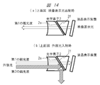
- the lens may be divided into two and the slope 2e may be installed inside.
- a thin film (dielectric multilayer film) 2f is formed on the slope 2e, transmits the first polarized wave as image light, and reflects the second polarized wave of the entering sunlight.
- the lens when it is necessary to make the lens thin, as shown in FIG. 15, the lens may be divided and a slope 2g may be provided.
- a thin film (dielectric multilayer film) 2h is formed on the slope 2g, transmits the first polarized wave as image light, and reflects the second polarized wave of the entering sunlight.
- the lens is divided into two, and the slope 2i inside the lens is placed so that the plane formed by the normal of the slope 2i and the optical axis coincides with the polarization direction of the second polarized wave, and the image light A film 2 j is provided that reflects the first polarized wave, and transmits the second polarized wave of the entering sunlight.
- the inclined surface for forming the thin film may be provided by inclining the incident surface or the exit surface of the lens.
- the above-described optical element 2 may be one in which a thin film (dielectric multilayer film) is formed on the bonding surface in a form in which a prism is bonded.
- the concave mirror and the thin film (dielectric multilayer film) formed on the lens surface described above Another variation is conceivable in the characteristics of the concave mirror and the thin film (dielectric multilayer film) formed on the lens surface described above.
- a thin film which transmits ultraviolet light and infrared light on the surface of the concave mirror and has a reflectance of the first polarized wave higher than that of the second polarized wave in the visible light region (dielectric multilayer A film is provided, and a thin film (dielectric multilayer film) which selectively transmits light of a specific wavelength used for image light in the visible light region is provided on the lens surface.
- the lens surface may not be inclined.
- the opening 41 formed in the upper part of the information display device 100 A light transmitting plate (transparent cover) may be provided which has a function of removing IR or UV, or a transmittance of the first polarized wave is higher than that of the second polarized wave. In that case, in addition to the reduction function of IR, UV, and the second polarized wave, it is possible to prevent external dust from invading the inside of the information display device 100.
- the optical element 2 As described above, according to the above-described concave mirror 1, the optical element 2, and the light transmitting plate (transparent cover) provided in the opening 41 of the housing 6, a large number of intrusions into the information display apparatus 100 from the opening 41 Of the sunlight containing spectral components, together with unnecessary components (IR and UV) in the information display device, the second polarized wave of sunlight described above is removed, and mainly visible light components are selectively extracted. It becomes possible.
- the light plate transparent cover
- the invading sunlight is removed from the normal light path, that is, it penetrates into the inside of the information display device 100 through the opening 41 at the upper part and the polarizing plate of the image display device 3 and its periphery It is preferable not to pass through the optical path leading to the like.
- FIG. 17 which is an exploded perspective view showing each component of the information display device 100 in a disassembled state from the back side, it can be pivoted inside the exterior cases 51 and 55 which is the housing 6
- the concave mirror drive unit 42 configured by an electric motor or the like for adjusting the position of the attached concave mirror 1 (direction different from the normal light path) ) Is moved to a preset position to reflect.
- the concave mirror drive unit 42 configured by an electric motor or the like for adjusting the position of the attached concave mirror 1 (direction different from the normal light path) ) Is moved to a preset position to reflect.
- the sunlight condensed by the concave mirror is returned to the image display device by rotating the concave mirror at a predetermined angle so that the sunlight does not return to the image display device. It becomes possible to provide the information display apparatus which improved the light resistance with respect to sunlight significantly by preventing.
- 100 information display device, 101 ... car, 1 ... concave mirror, 2 ... optical element, 3 ... image display device (liquid crystal display element, liquid crystal display panel), 5 ... projected member (front glass), 6 ... housing, V1: virtual image, 7: eye box (driver's eye), 4: light source device (backlight), 41: opening.
Landscapes
- Physics & Mathematics (AREA)
- Engineering & Computer Science (AREA)
- General Physics & Mathematics (AREA)
- Optics & Photonics (AREA)
- Chemical & Material Sciences (AREA)
- Mechanical Engineering (AREA)
- Combustion & Propulsion (AREA)
- Transportation (AREA)
- Inorganic Chemistry (AREA)
- Instrument Panels (AREA)
- Optical Filters (AREA)
- Polarising Elements (AREA)
Abstract
Description
本発明は、自動車や電車や航空機等(以下では、一般的に「乗り物」とも言う)のフロントガラスまたはコンバイナに画像を投影する情報表示装置に関し、特に、その画像をフロントガラス越しに虚像として観察するようにした投影光学系およびそれを用いた情報表示装置に関する。 The present invention relates to an information display apparatus for projecting an image on a windshield or a combiner of a car, a train, an aircraft, etc. (hereinafter generally referred to as "vehicle"), and in particular, observes the image as a virtual image through the windshield. And an information display apparatus using the same.
自動車のフロントガラスやコンバイナに映像光を投射して虚像を形成しルート情報や渋滞情報などの交通情報や燃料残量や冷却水温度等の自動車情報を表示するいわゆる、ヘッドアップディスプレイ(HUD:Head Up Display)装置が以下の特許文献1により既に知られている。 A so-called head-up display (HUD: Head that displays image light on a windshield or a combiner of a car to form a virtual image and displays traffic information such as route information and traffic congestion information and vehicle information such as fuel remaining amount and cooling water temperature). An Up Display) device is already known from US Pat.
この種の情報表示装置においては、運転者が虚像を観視できる領域を拡大することが望まれ、かつ、一方で前記虚像が高解像度で視認性が高いことも望まれている。 In this type of information display device, it is desirable to expand the area where the driver can view a virtual image, and on the other hand, it is also desired that the virtual image has high resolution and high visibility.
ヘッドアップディスプレイ装置は、映像表示装置に表示された映像を、凹面ミラー(凸レンズの作用)を含んだ光学系を用いて運転者に拡大像として虚像を提供する装置であり、最終反射面としてフロントガラスまたはコンバイナが必要となる。 The head-up display device is a device for providing a virtual image as an enlarged image to the driver using an optical system including a concave mirror (action of a convex lens) of an image displayed on the image display device, and fronts as a final reflection surface You will need glass or a combiner.
上述したヘッドアップディスプレイ装置に使用される映像表示装置としては、比較的に安価であり、かつ、高品位な映像が容易に得られることから、液晶表示素子が用いられることが多いが、一方で、昼間の所定条件化において太陽光がフロントガラスを通過して凹面ミラーで集光され液晶パネルと偏光板にダメージを与え性能が大幅に低下すると言う課題があった。 As a video display device used for the above-described head-up display device, a liquid crystal display element is often used because it is relatively inexpensive and a high quality image can be easily obtained. Under the condition of daytime, there is a problem that sunlight passes through the windshield and is condensed by the concave mirror to damage the liquid crystal panel and the polarizer, and the performance is significantly reduced.
そこで、例えば、以下の特許文献2により既に知られるように、映像表示装置である液晶表示素子の前方に配置されたガラス基板に貼着された偏光部材(フィルム)により、光源から出射して液晶表示素子を透過した偏光光を透過すると共に、外部から装置の内部に入射する太陽光のうち、前記偏光光とは偏光方向の異なる偏光成分を遮断する表示装置が提案されている。
Therefore, for example, as already known from
しかしながら、上述した従来技術、特に、特許文献2では、ガラス基板へ偏光部材を貼着した後の平面性の確保が難しく、表示映像の品質の低下が懸念される。なお、後にも詳述するが、近年においては、AR(拡張現実:Augmented Reality)-HUDと呼ばれる装置では、映像光をフロントガラスまたはコンバイナへ向けて投射して反射する凹面ミラーが大型化しており、そのため、より多くの太陽光が前記凹面ミラーにより集光されて装置内部に入射して液晶表示素子へダメージを与えることが懸念される。
However, in the above-described prior art, particularly in
そこで、本発明の目的は、より具体的には、所望する偏光方向または波長の光を選択的に反射/透過する特性を有した誘電体多層膜をミラーやレンズの表面に直接形成し、HUD装置の全体的な構成を考慮して、表示映像の品質を低下させることなく、より確実に外部から内部へ入射する太陽光を遮断/低減して、太陽光による液晶表示素子へのダメージを軽減する構成を備えた情報表示装置を提案することを目的とするものである。 Therefore, more specifically, the object of the present invention is to form a dielectric multilayer film having a characteristic of selectively reflecting / transmitting light of a desired polarization direction or wavelength directly on the surface of a mirror or a lens, In consideration of the overall configuration of the device, the sunlight incident on the inside from the outside can be more reliably blocked / reduced without reducing the quality of the display image, thereby reducing the damage to the liquid crystal display element by the sunlight It is an object of the present invention to propose an information display apparatus having the following configuration.
本発明によれば、上述した目的を達成するため、例えば、以下において特許請求の範囲でも述べるように、乗り物のフロントガラスまたはコンバイナに虚像の映像情報を表示する情報表示装置であって、前記情報表示装置の少なくとも一部を内部に収納する筐体を備え、前記筐体の一部には、開口部と、前記開口部に設けられた透明カバーと、を備え、前記筐体の内部には、前記映像情報を表示する映像光を生成する映像光生成手段と、前記映像光生成手段からの前記映像光を、前記乗り物の運転者が前記映像情報を前記フロントガラスの前方に虚像として認識可能とする光学系と、を備え、前記映像光生成手段は、前記フロントガラスに対してS偏光光を第1の偏光波とし、かつ、それと偏光方向が直交する偏光を第2の偏光波とした場合、前記映像光を、前記第1の偏光波によって生成するように構成され、前記開口部から前記筐体の内部に入射した外光の前記第2の偏光波と、前記第1の偏光波の一部を遮断する透過/反射率制御手段が設けられている情報表示装置が提供される。 According to the present invention, in order to achieve the above-mentioned object, it is an information display device for displaying virtual image video information on a windshield or a combiner of a vehicle, for example, as described in the following claims. The display device further includes a housing that accommodates at least a portion of the display device, and the housing includes an opening and a transparent cover provided in the opening. A driver of the vehicle can recognize the image information as a virtual image in front of the windshield as image light generating means for generating image light for displaying the image information, and the image light from the image light generating means And the image light generation means sets the S polarized light as the first polarized wave with respect to the front glass and the polarized light whose polarization direction is orthogonal to the first polarized wave as the second polarized wave. Place The image light is generated by the first polarized wave, and the second polarized wave of the external light incident on the inside of the casing from the opening and the first polarized wave There is provided an information display provided with transmission / reflectance control means for partially blocking.
上述した本発明によれば、表示映像の品質を低下させることなく、より確実に外部から内部へ入射する太陽光を遮断/低減し、太陽光による液晶表示素子へのダメージを軽減できる。 According to the present invention described above, it is possible to more reliably block / reduce the sunlight incident from the outside to the inside without reducing the quality of the display image, and to reduce the damage to the liquid crystal display element by the sunlight.
以下、図面等を用いて、本発明の実施例について詳細に説明する。なお、本発明は以下の説明に限定されるものではなく、本明細書に開示される技術的思想の範囲内において当業者による様々な変更および修正が可能である。また、本発明を説明するための全図において、同一の機能を有するものは、同一の符号を付け、その繰り返しの説明は省略する場合がある。 Hereinafter, the embodiment of the present invention will be described in detail using the drawings and the like. The present invention is not limited to the following description, and various changes and modifications can be made by those skilled in the art within the scope of the technical idea disclosed herein. Moreover, in all the drawings for explaining the present invention, what has the same function may attach the same numerals, and may omit explanation of the repetition.
<情報表示装置の概要>
図1は、本発明の一実施例に係る情報表示装置の周辺機器構成を示す概略構成図であり、ここでは、その一例として、特に、自動車のフロントガラスに画像を投影する情報表示装置100について説明する。
<Overview of Information Display Device>
FIG. 1 is a schematic configuration view showing a peripheral device configuration of an information display apparatus according to an embodiment of the present invention, and here, as an example thereof, in particular, an information display
図1に示すように、情報表示装置100は、運転者の眼7の視線において自車両の前方に虚像V1を形成するため、被投影部材5(本実施例では、フロントガラスの内面)にて反射された各種情報を虚像VI(Virtual Image)として表示する装置(いわゆる、HUD(Head Up Display)である。なお、被投影部材5は、情報が投影される部材であれば良く、前述したフロントガラスだけではなく、そのほか、コンバイナであっても良く、以下では、単に「フロントガラス」と記述する)。即ち、本実施例の情報表示装置100では、運転者の眼7の視線において自車両の前方に虚像を形成して運転者に視認させるものであれば良く、虚像として表示する情報としては、例えば、車両情報や監視カメラやアラウンドビュアーなどのカメラ(図示せず)で撮影した情報をも含むことは当然であろう。
As shown in FIG. 1, the
また、情報表示装置100では、情報を表示する映像光を投射する映像表示装置3と、前記映像表示装置3に表示された映像を凹面(自由曲面)ミラー1で虚像を形成する際に発生する歪や収差を補正するために補正用の光学素子2を設けている。
Further, in the
そして、情報表示装置100は、上記映像表示装置3とバックライト4を制御する制御装置40を備えている。なお、上記映像表示装置3とバックライト4などを含む光学部品は、以下に述べる虚像光学系であり、光を反射させる凹面ミラー1を含んでいる。また、この光学部品において反射した光は、被投影部材5にて反射されて運転者の眼7(EyeBox、EyePoint:図4参照)へと向かう。
The
上記の映像表示装置3としては、例えば、バックライトを有するLCD(Liquid Crystal Display)のほかに自発光のVFD(Vacuum Flourescent Display)などがある。
Examples of the
一方、上述した映像表示装置3の代わりに、投射装置によりスクリーンに映像を表示して、前述の凹面ミラー1で虚像とし被投影部材であるフロントガラス5またはコンバイナ(図示せず)で反射して運転者の眼7に向かわせても良い。なお、このようなスクリーンとしては、例えば、マイクロレンズを2次元状に配置したマイクロレンズアレイにより構成しても良い。
On the other hand, instead of the
ここで、虚像の歪みを低減するために凹面(自由曲面)ミラー1の形状は、図1に示す上部(相対的に運転者の視点との距離が短いフロントガラス5の下方で光線が反射する領域)では、拡大率が大きくなるように相対的に曲率半径が小さく、他方、下部(相対的に運転者の視点との距離が長いフロントガラス5の上方で光線が反射する領域)では、拡大率が小さくなるように相対的に曲率半径が大きくなる形状とすると良い。また、映像表示装置3を凹面ミラーの光軸に対して傾斜させることで上述した虚像倍率の違いを補正して発生する歪みそのものを低減することによっても、さらに良好な補正が実現できる。
Here, in order to reduce distortion of the virtual image, the shape of the concave (free-form surface)
一方、乗用車のフロントガラス5は、図2や図3にも示すように、本体垂直方向の曲率半径Rvと水平方向の曲率半径Rhが異なり、一般には、Rh>Rvの関係にある。このため、反射面としてフロントガラス5を捉えると、凹面ミラーのトロイダル面となる。このため、本実施例の情報表示装置100では、凹面ミラー1の形状はフロントガラス5の形状による虚像倍率を補正するように、即ち、フロントガラス5の垂直方向と水平方向の曲率半径の違いを補正するように水平方向と垂直方向で異なる平均曲率半径とすれば良い。この時、凹面ミラー1の形状は、光軸に対称な球面または非球面形状では、光軸からの距離rの関数であり、離れた場所の水平断面と垂直断面形状を個別に制御できないことから、自由曲面としてミラー面の光軸からの面の座標(x,y)の関数として補正することが好ましい。
On the other hand, as shown in FIG. 2 and FIG. 3, the
ここで再び、図1に戻り、映像表示装置3と凹面ミラー1の間には、さらに、透過型の光学部品として、例えば光学素子2を配置し、凹面ミラー1への光線の出射方向を制御することで凹面ミラー1の形状と合わせて歪曲収差の補正を行なう。それと同時に、前述したフロントガラス5の水平方向の曲率半径と垂直方向の曲率半径の違いによって生じる非点収差を含めた虚像の収差補正を実現する。
Here, again, returning to FIG. 1, for example, an
また、収差補正能力をさらに高めるために、上述した光学素子2を複数枚のレンズとしても良い。または、レンズの代わりに曲面(自由曲面)ミラーを配置して光路の折り返しと同時に凹面ミラー1への光線の入射位置を制御することで、歪曲収差を低減することもできる。以上にも述べたように、さらに、収差補正能力を向上させるたに最適設計された光学素子を凹面ミラー1と映像表示装置3の間に設けても、本発明の技術的思想または範囲を逸脱するものではないことは言うまでもない。さらに、上述した光学素子2の光軸方向の厚さを変化させることで、本来の収差補正のほかに凹面ミラー1と映像表示装置3の光学的な距離を変えて、虚像の表示位置を遠方から近接位置まで、連続的に変化させることもできる。
Further, in order to further enhance the aberration correction capability, the above-described
また、映像表示装置3を凹面ミラー1の光軸法線に対して傾けて配置することで虚像の上下方向の倍率の違いを補正しても良い。
Further, the
一方、光源としては、製品寿命が長い固体光源を採用することが好ましく、さらには、周囲温度の変動に対する光出力変化が少ないLED(Light Emitting Diode)として光の発散角を低減する光学手段を設け、かつ、PBS(Polarizing Beam Splitter)を用いて偏光変換を行なうことが好ましい。 On the other hand, as a light source, it is preferable to adopt a solid light source with a long product life, and further, an optical means is provided to reduce the light divergence angle as an LED (Light Emitting Diode) And, it is preferable to perform polarization conversion using PBS (Polarizing Beam Splitter).
液晶パネルのバックライト4側(光入射面)と光学素子2側(光出射面)には、ここでは図示しないが、偏光板が配置され、これにより、映像光のコントラスト比を高めている。バックライト4側(光入射面)に設ける偏光板には、偏光度が高いヨウ素系のものを採用すれば、高いコントラスト比が得られる。一方、光学素子2側(光出射面)には染料系の偏光板を用いることによれば、外光が入射した場合や環境温度が高い場合でも、高い信頼性を得ることが可能となる。
Although not shown here, a polarizing plate is disposed on the
映像表示装置3として液晶パネルを用いる場合、特に、運転者が偏光サングラスを着用している場合には、特定の偏波が遮蔽されて映像が見えない不具合が発生する。これを防ぐために、液晶パネルの光学素子2側に配置した偏光板の光学素子側にλ/4板を配置し、もって、特定の偏光方向に揃った映像光を円偏光に変換することが好ましい。
When a liquid crystal panel is used as the
制御装置40は、このようなナビゲーションシステム61から、自車両が走行している現在位置に対応する道路の制限速度や車線数、ナビゲーションシステム61に設定された自車両の移動予定経路などの各種の情報を、前景情報(即ち、上記虚像により自車両の前方に表示する情報)として取得する。
From the
運転支援ECU62は、周辺監視装置63での監視の結果として検出された障害物に従って駆動系や制御系を制御することで、運転支援制御を実現する制御装置であり、運転支援制御としては、例えば、クルーズコントロール、アダプティブクルーズコントロール、プリクラッシュセーフティ、レーンキーピングアシストなどの周知技術を含む。
The driving
周辺監視装置63は、自車両の周辺の状況を監視する装置であり、一例としては、自車両の周辺を撮影した画像に基づいて自車両の周辺に存在する物体を検出するカメラや、探査波を送受信した結果に基づいて自車両の周辺に存在する物体を検出する外界センサなどである。
The
制御装置40は、このような運転支援ECU62からの情報(例えば、先行車両までの距離および先行車両の方位、障害物や標識が存在する位置など)を前景情報として取得する。さらに、制御装置40には、イグニッション(IG)信号、および、自車状態情報が入力される。これらの情報のうち、自車状態情報とは、車両情報として取得される情報であり、例えば、内燃機関の燃料の残量や冷却水の温度など、予め規定された異常状態となったことを表す警告情報を含んでいる。また、方向指示器の操作結果や自車両の走行速度、さらには、シフトポジション情報なども含まれている。以上述べた制御装置40は、イグニッション信号が入力されると起動する。以上が、本願実施例の情報表示装置全体システムの説明である。
The
<太陽光の装置内への進入とその低減方法>
次に、車両の運転席における太陽光の情報表示装置内への侵入についての発明者等による検討結果について、以下に説明する。
<Invasion of sunlight into the device and its reduction method>
Next, the examination results by the inventors etc. about the penetration of sunlight into the information display device at the driver's seat of the vehicle will be described below.
図4は、車両の運転席の近傍における状態を示しており、上述した情報表示装置100は、車体を構成するボンネット44と天井板45との間に取り付けられたフロントガラス5の下方において、例えば、速度計42等の計器類を含むダッシュボードのボンネット側に配置されている。また、この図には、車両のハンドル43や、運転者である運転者の眼7と共に、車両の上方には昼間の太陽50が示されている。また、図5は、上記の状態から、特に、太陽50とフロントガラス5と運転者の眼7とを取り出して示している。
FIG. 4 shows a state in the vicinity of the driver's seat of the vehicle, and the above-described
太陽50からの強い光は、これら図4および図5において、白抜きの矢印で示すように、車両のフロントガラス5に対して入射角θ1で入射し、その一部がフロントガラス5により反射された後、残りの光は、情報表示装置100の上部に設けられた開口部41を通って前記情報表示装置100の内部に侵入する。なお、この時、特に、50度以上の入射角では、図6に示すように、太陽光のフロントガラスに対してS偏光成分(以降、「第1の偏光波」と定義)の多くは上記のフロントガラス5上で反射される。その結果、情報表示装置100内に侵入する太陽光の多くはフロントガラスに対してP偏光成分(以降第2の偏光波と定義)となる(図5の白抜き矢印を参照)。
The strong light from the
他方、情報表示装置100から出射される映像光は、図4および図5において実線の矢印で示すように、上記フロントガラス5またはコンバイナ(図示せず)において反射されて運転者の眼7に入射することとなる。
On the other hand, the image light emitted from the
より具体的には、太陽光などの外部からの自然光は、前記第1の偏光波と第2の偏光波が混ざった状態で存在する。前述したようにフロントガラスへの入射角度が50度を超える領域では、図6に示すように、ガラス面上での反射率は、第1の偏光波:S偏光や第2の偏光波:P偏光、さらには、入射角により、それぞれ異なる。 More specifically, natural light from the outside, such as sunlight, exists in a state in which the first polarized wave and the second polarized wave are mixed. As described above, in the region where the incident angle to the windshield exceeds 50 degrees, as shown in FIG. 6, the reflectance on the glass surface is the first polarized wave: S polarized light or the second polarized wave: P They differ depending on the polarization and further the incident angle.
そこで、本発明では、上述した知見に基づき、即ち、フロントガラス5を通して侵入する太陽光の多くは前記第2の偏光波成分であることを考慮し、情報表示装置100内に侵入する太陽光を遮断するためには、特に、第2の偏光波成分の低減が有効であること、加えて、情報表示装置100から投射される映像光としては、前記第1の偏光波成分を利用することが効果的であることを確認した。
Therefore, in the present invention, based on the above-described findings, that is, most of the sunlight entering through the
さらに、侵入する太陽光の第1の偏光波成分のうち、UV(Ultraviolet)(~400nm)とIR(Infrared)(800nm~)と、可視光(400nm~800nm)の一部、より具体的には、映像光として使用しない波長領域の低減も太陽光の遮断に有効である。 Furthermore, among the first polarized wave components of the invading sunlight, UV (Ultraviolet) (̃400 nm) and IR (Infrared) (800 nm ̃) and part of visible light (400 nm ̃800 nm), more specifically Is also effective in blocking sunlight in reducing the wavelength region not used as image light.
<情報表示装置の具体的な実施例>
続いて、上述した知見に基づいて構成された情報表示装置100のより具体的な光学的な構成について、以下に説明する。
<Specific Example of Information Display Device>
Subsequently, a more specific optical configuration of the
図7は、情報表示装置100の全体構成を示しており、上述したように、下流側から順に、フロントガラス5を介して虚像を形成する映像光を投射する凹面(自由曲面)ミラー1、その際に発生する歪や収差を補正するための補正用の光学素子2、映像表示装置3、バックライトを構成する光源装置4が設けられている。そして、情報表示装置100の内部に侵入する太陽光の前記第2の偏光波成分と、前記第1の偏光波成分のうち映像光に利用しない波長の光を低減するため、本実施例では、前記凹面ミラー1の表面には、映像光に利用する波長の光を効率よく反射し、前記波長以外のUV・IR・可視光を透過する薄膜(誘電体多層膜)を形成し、補正用の光学素子2の一面には、映像光に利用する第1の偏光波成分を効率よく透過し、第2の偏光波成分を反射する薄膜(誘電体多層膜)を形成する。
FIG. 7 shows the entire configuration of the
この凹面(自由曲面)ミラー1の表面上に形成した薄膜(誘電体多層膜)によれば、情報表示装置100であるHUD装置(特に、凹面ミラーが大型化しているAR(拡張現実:Augmented Reality)-HUD)の配置構成において、最も多くの太陽光が集光される凹面(自由曲面)ミラー1上で、UVおよびIR光と、可視光の一部を除去(透過)することができる。このこと、特に、凹面(自由曲面)ミラー1が、装置の光学系において、映像表示装置3から最も離れて配置されることによれば、前記UVおよびIRと、可視光の一部が光学素子2や映像表示装置3にまで到達してこれらを高温に加熱してダメージを与えることを、効率的に、防止することが可能となる。
According to the thin film (dielectric multilayer film) formed on the surface of the concave (free curved surface)
<凹面(自由曲面)ミラー表面の薄膜>
より具体的には、本実施例では、図8にも示すように、プラスチック等の凹面(自由曲面)ミラー1の基材1aの表面にIRとUVを透過し、図9に示すように、映像光に利用する特定波長の可視光(波長:略400~700nm)を選択的に反射する反射膜1bを設ける。反射膜の空気側には反射膜を保護する保護膜1cを設けることで耐傷性を向上することができる。
<Thin film on concave (free-form surface) mirror surface>
More specifically, in the present embodiment, as shown also in FIG. 8, IR and UV are transmitted to the surface of the
凹面(自由曲面)ミラーの基材1aは、上述した太陽光のうち反射しない波長成分の光を基材が吸収しないように透明性が高いものを選択する。プラスチック製基材として透明度が高い基材としては日本ゼオン株式会社のZEONEX(登録商標)、ポリカーボネイト、アクリル等がある。吸水率がほぼ0%で熱変形温度が高いZEONEXが最適であるが価格が高いため、熱変形温度が同等で吸水率が0.2%程度のポリカーボネイトを工夫して使用すると良い。成形性が最も高く安価なアクリルについては吸湿率が最大であるため防湿膜と反射膜を設けることが必須となる。
The
凹面(自由曲面)ミラーの基材が吸湿するのを防止するために図10に示すように反射面に成膜する反射膜に併せて、反対側の面に防湿膜として例えばSiN(窒化シリコン)を成膜して防湿膜1dを設けると良い。防湿膜1dであるSiNは太陽光を通過させるため基材での光吸収が発生せず熱変形を押さえることができる。この結果、ポリカーボネイトやアクリルで成形された凹面(自由曲面)ミラーにおいても吸湿による形状変化を防止することができる。
In order to prevent the substrate of the concave (free-form surface) mirror from absorbing moisture, it is combined with a reflective film to be formed on the reflective surface as shown in FIG. It is preferable to form a
上述した技術を適用した凹面(自由曲面)ミラーを通過した太陽光が情報表示装置内部で散乱しないように、図10に示した凹面ミラーの裏面には、光を吸収する材料で保持部(図示せず)を形成し放熱させると良い。 The back surface of the concave mirror shown in FIG. 10 is a holding portion made of a material that absorbs light so that the sunlight passing through the concave (free-form surface) mirror to which the above-described technology is applied is not scattered inside the information display device It is good to form and radiate heat (not shown).
<レンズ表面の薄膜>
一方、レンズ2の表面上に形成した薄膜(誘電体多層膜)によれば、情報表示装置100に侵入した太陽光の第2の偏光波成分の一部を除去(反射)することができる。より具体的には、本実施例では、図11に示すように、レンズ面のうち液晶表示装置側のレンズ面2aは、レンズ面2aの法線と光軸の成す面が、第2の偏光波の偏光方向と垂直に交わるように設置され、前記レンズ面2aには、図12に示すように、映像光である第1の偏光波を透過し、侵入した太陽光のうち第2の偏光波を反射する偏光膜2bを設ける。
<Thin film on lens surface>
On the other hand, according to the thin film (dielectric multilayer film) formed on the surface of the
上述した、レンズ表面上に形成した薄膜(誘電体多層膜)によって、侵入した太陽光の第2の偏光波成分を除去する手段としては、さらに、以下に記述する変形例がある。図13に示すように、レンズ面のうち凹面ミラー側のレンズ面2cは、レンズ面2cの法線と光軸の成す面が、第2の偏光波の偏光方向と垂直に交わるように設置され、レンズ面2cには、図12に示した、映像光である第1の偏光波を透過し、侵入した太陽光のうち第2の偏光波を反射する膜2dを設ける。
As means for removing the second polarized wave component of the entering sunlight by the thin film (dielectric multilayer film) formed on the lens surface described above, there are the following modified examples. As shown in FIG. 13, the lens surface 2c on the concave mirror side among the lens surfaces is disposed so that the surface formed by the normal of the lens surface 2c and the optical axis intersects perpendicularly with the polarization direction of the second polarized wave. The lens surface 2c is provided with a
また、レンズ表面を傾けて設置することが困難な場合は、図14に示すように、レンズを二つに分割し、内部に斜面2eを設置しても良い。斜面2eには、薄膜(誘電体多層膜)2fが形成され、映像光である第1の偏光波を透過し、侵入した太陽光のうち第2の偏光波を反射する。
If it is difficult to incline the lens surface and install it, as shown in FIG. 14, the lens may be divided into two and the
さらに、レンズを薄くする必要のある場合は、図15に示すように、レンズを分割し、斜面2gを設置してもよい。斜面2gには、薄膜(誘電体多層膜)2hが形成され、映像光である第1の偏光波を透過し、侵入した太陽光のうち第2の偏光波を反射する。
Furthermore, when it is necessary to make the lens thin, as shown in FIG. 15, the lens may be divided and a
そのほかの変形例として、図16に示す形態もある。この形態では、レンズを二つに分割し、レンズ内部の斜面2iが、前記斜面2iの法線と光軸の成す面が第2の偏光波の偏光方向と一致するように設置され、映像光である第1の偏光波を反射し、侵入した太陽光のうち第2の偏光波を透過する膜2jを設ける。なお、本形態においても、薄膜を形成する斜面は、レンズの入射面または出射面を傾けて設けても良い。
As another modified example, there is also a form shown in FIG. In this embodiment, the lens is divided into two, and the
また、ここでは図示しないが、上述した光学素子2は、プリズムを貼り合わせた形態で、貼り合わせ面に薄膜(誘電体多層膜)を形成したものでも良い。
Further, although not shown here, the above-described
上述した、凹面ミラーおよびレンズ表面に形成した薄膜(誘電体多層膜)の特性において、別の変形例が考えられる。ここでは図示しないが、凹面ミラーの表面上に、紫外線と赤外線を透過し、可視光領域で、第1の偏光波の反射率が第2の偏光波の反射率よりも高い薄膜(誘電体多層膜)を設け、レンズ表面上には、可視光領域で、映像光に利用する特定波長の光を選択的に透過する薄膜(誘電体多層膜)を設けている。なお、この変形例では、レンズ面を傾けなくても良い。 Another variation is conceivable in the characteristics of the concave mirror and the thin film (dielectric multilayer film) formed on the lens surface described above. Although not shown here, a thin film which transmits ultraviolet light and infrared light on the surface of the concave mirror and has a reflectance of the first polarized wave higher than that of the second polarized wave in the visible light region (dielectric multilayer A film is provided, and a thin film (dielectric multilayer film) which selectively transmits light of a specific wavelength used for image light in the visible light region is provided on the lens surface. In this modification, the lens surface may not be inclined.
さらに、ここでは図示しないが、上述したIRやUVの一部を除去する機能を備えた凹面(自由曲面)ミラー1に加え、さらに、情報表示装置100の上部に形成される開口部41に、IRやUVを除去する機能を有する、または、第1の偏光波の透過率が第2の偏光波の透過率よりも高い透光板(透明カバー)を設けても良い。なお、その場合には、IRやUV、第2の偏光波の低減機能に加え、外部の塵が情報表示装置100内部に侵入することを防止することが可能となる。
Furthermore, although not shown here, in addition to the concave (free-form surface)
このように、上述した凹面ミラー1や光学素子2、筐体6の開口部41に設けた透光板(透明カバー)によれば、開口部41から情報表示装置100の内部に侵入する多数のスペクトル成分を含む太陽光のうち、前記情報表示装置では不要な成分(IRやUV)と共に、上述した太陽光の第2の偏光波を除去し、主に可視光成分を選択的に取り出すことが可能となる。
As described above, according to the above-described
以上の情報表示装置100の光学構成によれば、フロントガラス5を介して装置の内部に侵入する太陽光から、不要なIRやUVを除去すると共に、映像表示装置3や周辺の偏光板等に対して炭化等の悪影響を及ぼす、太陽光の第2の偏光波成分と、第1の偏光波成分のうち映像光に利用しない波長の光を有効に低減する。即ち、太陽光による液晶表示素子や偏光板へのダメージを軽減することが可能となり、太陽光による情報表示装置100の性能の低下を抑制することが可能となる。
According to the above-described optical configuration of the
<そのほかの太陽光対策>
上述した情報表示装置100によれば、その動作中においては、凹面(自由曲面)ミラー1やレンズ2の、反射面または透過面に形成した誘電体多層膜、または、開口部41に設置した透光板(透明カバー)により、太陽光の不要なIRやUV、第2の偏光波の除去が可能である。しかしながら、例えば、駐車場などに車両を停車してエンジンを停止した状態あるいは変速機の状態をパーキングあるいはニュートラルにした状態では、前記情報表示装置100の動作は不要である。そこで、このような状態では、侵入する太陽光を通常の光路から排除し、即ち、上部の開口部41を通って情報表示装置100の内部に侵入して映像表示装置3やその周辺の偏光板等に至る光路を通らないようにすることが好ましい。
<Other solar measures>
According to the
一例として、情報表示装置100の各部品を分解した状態で背面側から示した展開斜視図である図17に示すように、その筐体6である外装ケース51、55の内部において回動可能に取り付けられた凹面ミラー1を、その位置を調整するための電動モータ等により構成される凹面ミラー駆動部42により、侵入する太陽光が映像表示装置3に至らない方向(通常の光路とは異なる方向)に反射する予め設定された位置に移動される。このことによれば、特に、侵入する太陽光が問題となる車両の停止時等において、前記侵入光が逆進する光路を変更することにより、より確実に、真夏などの強い太陽光の下においても、太陽光が情報表示装置の光学部品である映像表示装置3や周辺の偏光板、さらには、バックライト4等を破損・劣化させてしまう事態を防止することが可能となる。
As an example, as shown in FIG. 17 which is an exploded perspective view showing each component of the
即ち、情報表示装置を使用しない場合には太陽光が映像表示装置に戻らないように凹面ミラーを所定の角度を回転させることで凹面ミラーにより集光される太陽光が映像表示装置に戻ることを防止することで太陽光に対する耐光性を大幅に向上した情報表示装置を提供することが可能となる。 That is, when the information display device is not used, the sunlight condensed by the concave mirror is returned to the image display device by rotating the concave mirror at a predetermined angle so that the sunlight does not return to the image display device. It becomes possible to provide the information display apparatus which improved the light resistance with respect to sunlight significantly by preventing.
以上、種々の実施例について詳述したが、しかしながら、本発明は、上述した実施例のみに限定されるものではなく、様々な変形例が含まれる。例えば、上記した実施例は本発明を分かりやすく説明するためにシステム全体を詳細に説明したものであり、必ずしも説明した全ての構成を備えるものに限定されるものではない。また、ある実施例の構成の一部をほかの実施例の構成に置き換えることが可能であり、また、ある実施例の構成にほかの実施例の構成を加えることも可能である。また、各実施例の構成の一部について、ほかの構成の追加・削除・置換をすることが可能である。 As mentioned above, although various embodiments were explained in full detail, however, this invention is not limited only to the embodiment mentioned above, and various modifications are included. For example, the above-described embodiment describes the entire system in detail in order to explain the present invention in an easy-to-understand manner, and is not necessarily limited to one having all the configurations described. Further, part of the configuration of one embodiment can be replaced with the configuration of another embodiment, and the configuration of another embodiment can be added to the configuration of one embodiment. In addition, with respect to a part of the configuration of each embodiment, it is possible to add, delete, and replace other configurations.
100…情報表示装置、101…自動車、1…凹面ミラー、2…光学素子、3…映像表示装置(液晶表示素子、液晶表示パネル)、5…被投影部材(フロントガラス)、6…筐体、V1…虚像、7…アイボックス(運転者の眼)、4…光源装置(バックライト)、41…開口部。 100 ... information display device, 101 ... car, 1 ... concave mirror, 2 ... optical element, 3 ... image display device (liquid crystal display element, liquid crystal display panel), 5 ... projected member (front glass), 6 ... housing, V1: virtual image, 7: eye box (driver's eye), 4: light source device (backlight), 41: opening.
Claims (13)
前記情報表示装置の少なくとも一部を内部に収納する筐体を備え、
前記筐体の一部には、開口部と、前記開口部に設けられた透明カバーと、を備え、
前記筐体の内部には、
前記映像情報を表示する映像光を生成する映像光生成手段と、
前記映像光生成手段からの前記映像光を、前記乗り物の運転者が前記映像情報を前記フロントガラスの前方に虚像として認識可能とする光学系と、を備え、
前記映像光生成手段は、前記フロントガラスまたはコンバイナに対してS偏光光を第1の偏光波とし、かつ、それと偏光方向が直交する偏光を第2の偏光波とした場合、前記映像光を、前記第1の偏光波によって生成するように構成され、
前記開口部から前記筐体の内部に入射した外光の前記第2の偏光波と、前記第1の偏光波の一部を遮断する透過/反射率制御手段が設けられている、情報表示装置。 An information display apparatus for displaying virtual image information on a windshield or a combiner of a vehicle, comprising:
A housing for housing at least a part of the information display device inside;
A part of the housing includes an opening and a transparent cover provided in the opening,
Inside the case,
Video light generating means for generating video light for displaying the video information;
And an optical system that enables the driver of the vehicle to recognize the image information as a virtual image in front of the windshield, the image light from the image light generation means.
When the image light generation unit sets the S polarized light as a first polarized wave and the polarized light whose polarization direction is orthogonal to that of the front glass or the combiner as a second polarized wave, the image light is Configured to be generated by the first polarized wave,
10. An information display device, comprising transmission / reflectance control means for blocking a part of the second polarized wave of external light incident on the inside of the casing from the opening and the first polarized wave. .
前記光学系は、少なくとも1つ以上の反射部材、および/または、少なくとも1つ以上の透過部材から構成されている、情報表示装置。 In the information display device according to claim 1,
The information display device, wherein the optical system is composed of at least one or more reflecting members and / or at least one or more transmitting members.
前記反射部材の少なくとも1つの反射面には、可視光領域で、前記第1の偏光波の反射率が、前記第2の偏光波の反射率よりも高く、両偏光の紫外線と赤外線を透過する誘電体多層膜が形成されている、情報表示装置。 In the information display device according to claim 2,
The reflectance of the first polarized wave is higher than the reflectance of the second polarized wave in the visible light region on at least one of the reflecting surfaces of the reflecting member, and ultraviolet light and infrared light of both polarized light are transmitted. An information display device in which a dielectric multilayer film is formed.
前記透過部材の少なくとも1つの透過面には、可視光領域のうち、前記映像光に利用する波長を透過し、前記映像光と異なる波長を反射する誘電体多層膜が形成されている、情報表示装置。 In the information display device according to claim 3,
In at least one transmission surface of the transmission member, a dielectric multilayer film is formed which transmits a wavelength used for the image light in a visible light region and reflects a wavelength different from the image light. apparatus.
前記反射面と異なる少なくとも1つの反射面には、可視光領域のうち、前記映像光に利用する波長を反射し、前記映像光と異なる波長を透過する誘電体多層膜が形成されている、情報表示装置。 In the information display device according to claim 3,
In at least one reflective surface different from the reflective surface, a dielectric multilayer film is formed which reflects a wavelength used for the image light in a visible light region and transmits a wavelength different from the image light. Display device.
前記透過部材の少なくとも1つの透過面には、可視光領域で、前記第1の偏光波の透過率が、前記第2の偏光波の透過率よりも高い誘電体多層膜が形成され、前記透過面に対して前記映像光が前記第1の偏光波となるように、前記透過部材が設置されている、情報表示装置。 In the information display device according to claim 2,
A dielectric multilayer film having a transmittance of the first polarized wave higher than that of the second polarized wave in the visible light region is formed on at least one of the transmitting surfaces of the transmitting member, and the transmission is performed. The information display device, wherein the transmission member is installed such that the image light is the first polarized wave with respect to the surface.
前記反射部材の少なくとも1つの反射面に、可視光領域のうち、前記映像光に利用する波長を反射し、前記映像光と異なる波長を透過すると共に、紫外線と赤外線を透過する誘電体多層膜が形成されている、情報表示装置。 In the information display device according to claim 6,
A dielectric multilayer film which reflects a wavelength used for the image light in a visible light region and transmits a wavelength different from the image light and transmits ultraviolet light and infrared light on at least one reflection surface of the reflection member An information display device being formed.
前記透過面と異なる少なくとも1つの透過面には、可視光領域のうち、前記映像光に利用する波長を透過し、前記映像光と異なる波長を反射する誘電体多層膜が形成されている、情報表示装置。 In the information display device according to claim 6,
In at least one transmission surface different from the transmission surface, a dielectric multilayer film is formed which transmits the wavelength used for the image light in the visible light region and reflects the wavelength different from the image light. Display device.
前記透明カバーが、前記映像光と同じ偏光方向の光に対して高い透過性を有し、前記映像光と直交する偏光方向の光に対して低い透過性を有する、情報表示装置。 In the information display device according to claim 2,
The information display device, wherein the transparent cover has high transparency to light in the same polarization direction as the image light and has low transparency to light in a polarization direction orthogonal to the image light.
前記反射部材の少なくとも1つの反射面に、可視光線を反射し、紫外線と赤外線を透過する誘電体多層膜が形成されている、情報表示装置。 In the information display device according to claim 9,
An information display device, wherein a dielectric multilayer film which reflects visible light and transmits ultraviolet light and infrared light is formed on at least one reflection surface of the reflection member.
前記誘電体多層膜が、可視光領域のうち、前記映像光に利用する波長を反射し、前記映像光と異なる波長の光を透過する、情報表示装置。 In the information display device according to claim 10,
The information display device, wherein the dielectric multilayer film reflects a wavelength used for the image light in a visible light region and transmits light of a wavelength different from the image light.
前記透過部材の少なくとも1つの透過面に、可視光領域のうち、前記映像光に利用する波長を透過し、前記映像光と異なる波長の光を反射する誘電体多層膜が形成されている、情報表示装置。 In the information display device according to claim 10,
In the visible light region, a dielectric multilayer film is formed on at least one transmission surface of the transmission member, which transmits a wavelength used for the image light and reflects light of a wavelength different from the image light. Display device.
前記反射面に形成された、赤外線を透過する誘電体多層膜の代わりに、前記透明カバー、または/および、前記反射部材、または/および、前記透過部材の材料に、可視光を透過し、赤外線を吸収する樹脂材料を用いている、情報表示装置。 The information display device according to any one of claims 1 to 12.
Instead of the infrared light transmitting dielectric multi-layered film formed on the reflection surface, visible light is transmitted to the transparent cover and / or the reflection member or / and the material of the transmission member, and the infrared light is transmitted An information display device that uses a resin material that absorbs
Priority Applications (5)
| Application Number | Priority Date | Filing Date | Title |
|---|---|---|---|
| JP2019538971A JP6839764B2 (en) | 2017-09-04 | 2018-05-25 | Information display device |
| US16/622,370 US11921287B2 (en) | 2017-09-04 | 2018-05-25 | Information display apparatus |
| CN201880040531.XA CN110753875B (en) | 2017-09-04 | 2018-05-25 | information display device |
| US18/430,840 US12332435B2 (en) | 2017-09-04 | 2024-02-02 | Vehicle |
| US19/207,561 US20250271670A1 (en) | 2017-09-04 | 2025-05-14 | Vehicle |
Applications Claiming Priority (2)
| Application Number | Priority Date | Filing Date | Title |
|---|---|---|---|
| JP2017-169304 | 2017-09-04 | ||
| JP2017169304 | 2017-09-04 |
Related Child Applications (2)
| Application Number | Title | Priority Date | Filing Date |
|---|---|---|---|
| US16/622,370 A-371-Of-International US11921287B2 (en) | 2017-09-04 | 2018-05-25 | Information display apparatus |
| US18/430,840 Continuation US12332435B2 (en) | 2017-09-04 | 2024-02-02 | Vehicle |
Publications (1)
| Publication Number | Publication Date |
|---|---|
| WO2019044072A1 true WO2019044072A1 (en) | 2019-03-07 |
Family
ID=65527565
Family Applications (1)
| Application Number | Title | Priority Date | Filing Date |
|---|---|---|---|
| PCT/JP2018/020215 Ceased WO2019044072A1 (en) | 2017-09-04 | 2018-05-25 | Information display device |
Country Status (4)
| Country | Link |
|---|---|
| US (3) | US11921287B2 (en) |
| JP (1) | JP6839764B2 (en) |
| CN (1) | CN110753875B (en) |
| WO (1) | WO2019044072A1 (en) |
Cited By (6)
| Publication number | Priority date | Publication date | Assignee | Title |
|---|---|---|---|---|
| WO2021145374A1 (en) * | 2020-01-15 | 2021-07-22 | 日本精機株式会社 | Head-up display device |
| CN114379470A (en) * | 2022-01-17 | 2022-04-22 | 福耀玻璃工业集团股份有限公司 | Vehicle-mounted system |
| JP2022155929A (en) * | 2021-03-31 | 2022-10-14 | セイコーエプソン株式会社 | Virtual image display device |
| JP2023506582A (en) * | 2020-01-31 | 2023-02-16 | スリーエム イノベイティブ プロパティズ カンパニー | Polarizing beam splitters and hot mirrors for head-up displays |
| JP2023539877A (en) * | 2021-03-04 | 2023-09-20 | 浙江水晶光電科技股▲フン▼有限公司 | Optical modules for head-up displays, optical systems for head-up displays, and vehicles |
| WO2024090552A1 (en) * | 2022-10-28 | 2024-05-02 | 株式会社小糸製作所 | Image projection device and image display device |
Families Citing this family (12)
| Publication number | Priority date | Publication date | Assignee | Title |
|---|---|---|---|---|
| CN111752046B (en) * | 2015-10-15 | 2023-06-02 | 麦克赛尔株式会社 | HUD |
| CN110753875B (en) * | 2017-09-04 | 2022-03-01 | 麦克赛尔株式会社 | information display device |
| WO2019116731A1 (en) * | 2017-12-11 | 2019-06-20 | パナソニックIpマネジメント株式会社 | Head-up display and moving body with head-up display mounted thereon |
| US10884249B2 (en) * | 2018-10-23 | 2021-01-05 | Panasonic Automotive Systems Company Of America, Division Of Panasonic Corporation Of North America | Combiner head up display with separate infrared function |
| CN210072208U (en) * | 2019-05-29 | 2020-02-14 | 3M创新有限公司 | display device |
| US11156833B2 (en) * | 2019-07-08 | 2021-10-26 | Ford Global Technologies, Llc | Optical extender for vehicle heads up displays |
| JP7152449B2 (en) * | 2020-08-05 | 2022-10-12 | 矢崎総業株式会社 | vehicle display |
| US12388970B2 (en) * | 2021-05-28 | 2025-08-12 | Kyocera Corporation | Method for setting three-dimensional image display system |
| CN113448102B (en) * | 2021-06-30 | 2022-12-27 | 上海天马微电子有限公司 | Head-up display |
| US12351023B2 (en) * | 2021-06-30 | 2025-07-08 | Panasonic Automotive Systems Co., Ltd. | Display device |
| US12397623B2 (en) * | 2022-03-04 | 2025-08-26 | Xinyu Zhu | Method for enhancing interior display readability in motorized objects and system therefor |
| JP2025012233A (en) * | 2023-07-13 | 2025-01-24 | 矢崎総業株式会社 | Head-up display device |
Citations (8)
| Publication number | Priority date | Publication date | Assignee | Title |
|---|---|---|---|---|
| JPS62275845A (en) * | 1986-05-23 | 1987-11-30 | Nissan Motor Co Ltd | Display device for vehicle |
| US5486840A (en) * | 1994-03-21 | 1996-01-23 | Delco Electronics Corporation | Head up display with incident light filter |
| JP2006039029A (en) * | 2004-07-23 | 2006-02-09 | Murakami Corp | Display device |
| JP2013057897A (en) * | 2011-09-09 | 2013-03-28 | Yazaki Corp | Display device for vehicle |
| JP2016065905A (en) * | 2014-09-23 | 2016-04-28 | 株式会社デンソー | Head-up display |
| JP2016197173A (en) * | 2015-04-03 | 2016-11-24 | 株式会社デンソー | Head-up display device |
| JP2017009666A (en) * | 2015-06-17 | 2017-01-12 | 株式会社デンソー | Head-up display device |
| JP2017102347A (en) * | 2015-12-03 | 2017-06-08 | 株式会社デンソー | Head-up display device |
Family Cites Families (19)
| Publication number | Priority date | Publication date | Assignee | Title |
|---|---|---|---|---|
| JPH0681286B2 (en) * | 1988-03-30 | 1994-10-12 | 日産自動車株式会社 | Vehicle display |
| US4973132A (en) * | 1989-10-27 | 1990-11-27 | Hughes Aircraft Company | Polarized holographic heads up display |
| JP4114194B2 (en) | 1998-10-29 | 2008-07-09 | 日本精機株式会社 | Head-up display device |
| US8861087B2 (en) * | 2007-08-12 | 2014-10-14 | Toyota Motor Corporation | Multi-layer photonic structures having omni-directional reflectivity and coatings incorporating the same |
| JP2010275845A (en) | 2009-05-27 | 2010-12-09 | Masaomi Wada | Sliding door having pull on both right and left sides |
| TWI588192B (en) | 2011-10-14 | 2017-06-21 | Jsr Corp | Optical filter, solid-state imaging device and camera module using the optical filter |
| JP5988074B2 (en) * | 2012-01-27 | 2016-09-07 | 日本精機株式会社 | Vehicle head-up display device and self-check method thereof |
| JP6131766B2 (en) * | 2013-08-06 | 2017-05-24 | 株式会社デンソー | Head-up display device for vehicle |
| JP6291917B2 (en) * | 2014-03-07 | 2018-03-14 | 富士通オプティカルコンポーネンツ株式会社 | Polarization combiner and optical modulator |
| JP6336572B2 (en) * | 2014-03-20 | 2018-06-06 | 富士フイルム株式会社 | Reflective member, projection screen, combiner, and heat shield member |
| JP2015194707A (en) | 2014-03-27 | 2015-11-05 | パナソニックIpマネジメント株式会社 | Display device |
| CN106716229B (en) * | 2014-09-29 | 2020-03-24 | 富士胶片株式会社 | Projection image display member and projection image display system |
| JP6768567B2 (en) * | 2016-11-04 | 2020-10-14 | 富士フイルム株式会社 | Windshield glass, heads-up display system, and half mirror film |
| JP2018084596A (en) * | 2016-11-21 | 2018-05-31 | マクセル株式会社 | Information display device |
| CN106483663B (en) * | 2016-12-08 | 2019-01-11 | 福耀玻璃工业集团股份有限公司 | A kind of automobile head-up-display system |
| CN107045203B (en) * | 2017-03-27 | 2019-08-20 | 福耀玻璃工业集团股份有限公司 | A kind of head-up-display system |
| CN110753875B (en) * | 2017-09-04 | 2022-03-01 | 麦克赛尔株式会社 | information display device |
| JP2019144415A (en) * | 2018-02-21 | 2019-08-29 | 矢崎総業株式会社 | Projection device and display device for vehicle |
| US11433815B2 (en) * | 2019-05-31 | 2022-09-06 | Panasonic Intellectual Property Management Co., Ltd. | Display system |
-
2018
- 2018-05-25 CN CN201880040531.XA patent/CN110753875B/en active Active
- 2018-05-25 WO PCT/JP2018/020215 patent/WO2019044072A1/en not_active Ceased
- 2018-05-25 JP JP2019538971A patent/JP6839764B2/en active Active
- 2018-05-25 US US16/622,370 patent/US11921287B2/en active Active
-
2024
- 2024-02-02 US US18/430,840 patent/US12332435B2/en active Active
-
2025
- 2025-05-14 US US19/207,561 patent/US20250271670A1/en active Pending
Patent Citations (8)
| Publication number | Priority date | Publication date | Assignee | Title |
|---|---|---|---|---|
| JPS62275845A (en) * | 1986-05-23 | 1987-11-30 | Nissan Motor Co Ltd | Display device for vehicle |
| US5486840A (en) * | 1994-03-21 | 1996-01-23 | Delco Electronics Corporation | Head up display with incident light filter |
| JP2006039029A (en) * | 2004-07-23 | 2006-02-09 | Murakami Corp | Display device |
| JP2013057897A (en) * | 2011-09-09 | 2013-03-28 | Yazaki Corp | Display device for vehicle |
| JP2016065905A (en) * | 2014-09-23 | 2016-04-28 | 株式会社デンソー | Head-up display |
| JP2016197173A (en) * | 2015-04-03 | 2016-11-24 | 株式会社デンソー | Head-up display device |
| JP2017009666A (en) * | 2015-06-17 | 2017-01-12 | 株式会社デンソー | Head-up display device |
| JP2017102347A (en) * | 2015-12-03 | 2017-06-08 | 株式会社デンソー | Head-up display device |
Cited By (9)
| Publication number | Priority date | Publication date | Assignee | Title |
|---|---|---|---|---|
| WO2021145374A1 (en) * | 2020-01-15 | 2021-07-22 | 日本精機株式会社 | Head-up display device |
| JP2023506582A (en) * | 2020-01-31 | 2023-02-16 | スリーエム イノベイティブ プロパティズ カンパニー | Polarizing beam splitters and hot mirrors for head-up displays |
| JP2023539877A (en) * | 2021-03-04 | 2023-09-20 | 浙江水晶光電科技股▲フン▼有限公司 | Optical modules for head-up displays, optical systems for head-up displays, and vehicles |
| JP7618019B2 (en) | 2021-03-04 | 2025-01-20 | 浙江水晶光電科技股▲フン▼有限公司 | Optical module for head-up display and optical system for head-up display, vehicle |
| JP2022155929A (en) * | 2021-03-31 | 2022-10-14 | セイコーエプソン株式会社 | Virtual image display device |
| JP7625938B2 (en) | 2021-03-31 | 2025-02-04 | セイコーエプソン株式会社 | Virtual Image Display |
| CN114379470A (en) * | 2022-01-17 | 2022-04-22 | 福耀玻璃工业集团股份有限公司 | Vehicle-mounted system |
| CN114379470B (en) * | 2022-01-17 | 2023-10-20 | 福耀玻璃工业集团股份有限公司 | Vehicle system |
| WO2024090552A1 (en) * | 2022-10-28 | 2024-05-02 | 株式会社小糸製作所 | Image projection device and image display device |
Also Published As
| Publication number | Publication date |
|---|---|
| JPWO2019044072A1 (en) | 2020-04-02 |
| US20250271670A1 (en) | 2025-08-28 |
| US20240176139A1 (en) | 2024-05-30 |
| US12332435B2 (en) | 2025-06-17 |
| JP6839764B2 (en) | 2021-03-10 |
| US11921287B2 (en) | 2024-03-05 |
| US20200201037A1 (en) | 2020-06-25 |
| CN110753875A (en) | 2020-02-04 |
| CN110753875B (en) | 2022-03-01 |
Similar Documents
| Publication | Publication Date | Title |
|---|---|---|
| JP6839764B2 (en) | Information display device | |
| JP7233493B2 (en) | Information display device | |
| JP7698097B2 (en) | information display device | |
| JP7081021B2 (en) | Information display device | |
| US20260118566A1 (en) | Information display device | |
| WO2020166286A1 (en) | Vehicle information display apparatus and information display system for vehicle | |
| JP6940361B2 (en) | Information display device | |
| WO2020183844A1 (en) | Head-up display device | |
| JP7122919B2 (en) | Information display device and reflecting mirror used therefor | |
| JP7290919B2 (en) | Information display device |
Legal Events
| Date | Code | Title | Description |
|---|---|---|---|
| 121 | Ep: the epo has been informed by wipo that ep was designated in this application |
Ref document number: 18849529 Country of ref document: EP Kind code of ref document: A1 |
|
| ENP | Entry into the national phase |
Ref document number: 2019538971 Country of ref document: JP Kind code of ref document: A |
|
| NENP | Non-entry into the national phase |
Ref country code: DE |
|
| 122 | Ep: pct application non-entry in european phase |
Ref document number: 18849529 Country of ref document: EP Kind code of ref document: A1 |