WO2017188080A1 - Field-sequential image display device and image display method - Google Patents
Field-sequential image display device and image display method Download PDFInfo
- Publication number
- WO2017188080A1 WO2017188080A1 PCT/JP2017/015683 JP2017015683W WO2017188080A1 WO 2017188080 A1 WO2017188080 A1 WO 2017188080A1 JP 2017015683 W JP2017015683 W JP 2017015683W WO 2017188080 A1 WO2017188080 A1 WO 2017188080A1
- Authority
- WO
- WIPO (PCT)
- Prior art keywords
- image data
- coefficient
- display device
- image display
- saturation
- Prior art date
- Legal status (The legal status is an assumption and is not a legal conclusion. Google has not performed a legal analysis and makes no representation as to the accuracy of the status listed.)
- Ceased
Links
Images


Classifications
-
- G—PHYSICS
- G09—EDUCATION; CRYPTOGRAPHY; DISPLAY; ADVERTISING; SEALS
- G09G—ARRANGEMENTS OR CIRCUITS FOR CONTROL OF INDICATING DEVICES USING STATIC MEANS TO PRESENT VARIABLE INFORMATION
- G09G5/00—Control arrangements or circuits for visual indicators common to cathode-ray tube indicators and other visual indicators
- G09G5/10—Intensity circuits
-
- G—PHYSICS
- G09—EDUCATION; CRYPTOGRAPHY; DISPLAY; ADVERTISING; SEALS
- G09G—ARRANGEMENTS OR CIRCUITS FOR CONTROL OF INDICATING DEVICES USING STATIC MEANS TO PRESENT VARIABLE INFORMATION
- G09G3/00—Control arrangements or circuits, of interest only in connection with visual indicators other than cathode-ray tubes
- G09G3/20—Control arrangements or circuits, of interest only in connection with visual indicators other than cathode-ray tubes for presentation of an assembly of a number of characters, e.g. a page, by composing the assembly by combination of individual elements arranged in a matrix no fixed position being assigned to or needed to be assigned to the individual characters or partial characters
- G09G3/34—Control arrangements or circuits, of interest only in connection with visual indicators other than cathode-ray tubes for presentation of an assembly of a number of characters, e.g. a page, by composing the assembly by combination of individual elements arranged in a matrix no fixed position being assigned to or needed to be assigned to the individual characters or partial characters by control of light from an independent source
- G09G3/3406—Control of illumination source
- G09G3/3413—Details of control of colour illumination sources
-
- G—PHYSICS
- G09—EDUCATION; CRYPTOGRAPHY; DISPLAY; ADVERTISING; SEALS
- G09G—ARRANGEMENTS OR CIRCUITS FOR CONTROL OF INDICATING DEVICES USING STATIC MEANS TO PRESENT VARIABLE INFORMATION
- G09G3/00—Control arrangements or circuits, of interest only in connection with visual indicators other than cathode-ray tubes
- G09G3/20—Control arrangements or circuits, of interest only in connection with visual indicators other than cathode-ray tubes for presentation of an assembly of a number of characters, e.g. a page, by composing the assembly by combination of individual elements arranged in a matrix no fixed position being assigned to or needed to be assigned to the individual characters or partial characters
- G09G3/34—Control arrangements or circuits, of interest only in connection with visual indicators other than cathode-ray tubes for presentation of an assembly of a number of characters, e.g. a page, by composing the assembly by combination of individual elements arranged in a matrix no fixed position being assigned to or needed to be assigned to the individual characters or partial characters by control of light from an independent source
- G09G3/36—Control arrangements or circuits, of interest only in connection with visual indicators other than cathode-ray tubes for presentation of an assembly of a number of characters, e.g. a page, by composing the assembly by combination of individual elements arranged in a matrix no fixed position being assigned to or needed to be assigned to the individual characters or partial characters by control of light from an independent source using liquid crystals
- G09G3/3607—Control arrangements or circuits, of interest only in connection with visual indicators other than cathode-ray tubes for presentation of an assembly of a number of characters, e.g. a page, by composing the assembly by combination of individual elements arranged in a matrix no fixed position being assigned to or needed to be assigned to the individual characters or partial characters by control of light from an independent source using liquid crystals for displaying colours or for displaying grey scales with a specific pixel layout, e.g. using sub-pixels
-
- G—PHYSICS
- G09—EDUCATION; CRYPTOGRAPHY; DISPLAY; ADVERTISING; SEALS
- G09G—ARRANGEMENTS OR CIRCUITS FOR CONTROL OF INDICATING DEVICES USING STATIC MEANS TO PRESENT VARIABLE INFORMATION
- G09G5/00—Control arrangements or circuits for visual indicators common to cathode-ray tube indicators and other visual indicators
- G09G5/02—Control arrangements or circuits for visual indicators common to cathode-ray tube indicators and other visual indicators characterised by the way in which colour is displayed
-
- H—ELECTRICITY
- H04—ELECTRIC COMMUNICATION TECHNIQUE
- H04N—PICTORIAL COMMUNICATION, e.g. TELEVISION
- H04N9/00—Details of colour television systems
- H04N9/12—Picture reproducers
- H04N9/30—Picture reproducers using solid-state colour display devices
-
- G—PHYSICS
- G09—EDUCATION; CRYPTOGRAPHY; DISPLAY; ADVERTISING; SEALS
- G09G—ARRANGEMENTS OR CIRCUITS FOR CONTROL OF INDICATING DEVICES USING STATIC MEANS TO PRESENT VARIABLE INFORMATION
- G09G2310/00—Command of the display device
- G09G2310/02—Addressing, scanning or driving the display screen or processing steps related thereto
- G09G2310/0235—Field-sequential colour display
-
- G—PHYSICS
- G09—EDUCATION; CRYPTOGRAPHY; DISPLAY; ADVERTISING; SEALS
- G09G—ARRANGEMENTS OR CIRCUITS FOR CONTROL OF INDICATING DEVICES USING STATIC MEANS TO PRESENT VARIABLE INFORMATION
- G09G2320/00—Control of display operating conditions
- G09G2320/04—Maintaining the quality of display appearance
- G09G2320/041—Temperature compensation
-
- G—PHYSICS
- G09—EDUCATION; CRYPTOGRAPHY; DISPLAY; ADVERTISING; SEALS
- G09G—ARRANGEMENTS OR CIRCUITS FOR CONTROL OF INDICATING DEVICES USING STATIC MEANS TO PRESENT VARIABLE INFORMATION
- G09G2320/00—Control of display operating conditions
- G09G2320/06—Adjustment of display parameters
- G09G2320/0626—Adjustment of display parameters for control of overall brightness
- G09G2320/0646—Modulation of illumination source brightness and image signal correlated to each other
-
- G—PHYSICS
- G09—EDUCATION; CRYPTOGRAPHY; DISPLAY; ADVERTISING; SEALS
- G09G—ARRANGEMENTS OR CIRCUITS FOR CONTROL OF INDICATING DEVICES USING STATIC MEANS TO PRESENT VARIABLE INFORMATION
- G09G2320/00—Control of display operating conditions
- G09G2320/06—Adjustment of display parameters
- G09G2320/0666—Adjustment of display parameters for control of colour parameters, e.g. colour temperature
-
- G—PHYSICS
- G09—EDUCATION; CRYPTOGRAPHY; DISPLAY; ADVERTISING; SEALS
- G09G—ARRANGEMENTS OR CIRCUITS FOR CONTROL OF INDICATING DEVICES USING STATIC MEANS TO PRESENT VARIABLE INFORMATION
- G09G2320/00—Control of display operating conditions
- G09G2320/06—Adjustment of display parameters
- G09G2320/0673—Adjustment of display parameters for control of gamma adjustment, e.g. selecting another gamma curve
-
- G—PHYSICS
- G09—EDUCATION; CRYPTOGRAPHY; DISPLAY; ADVERTISING; SEALS
- G09G—ARRANGEMENTS OR CIRCUITS FOR CONTROL OF INDICATING DEVICES USING STATIC MEANS TO PRESENT VARIABLE INFORMATION
- G09G2340/00—Aspects of display data processing
- G09G2340/06—Colour space transformation
-
- G—PHYSICS
- G09—EDUCATION; CRYPTOGRAPHY; DISPLAY; ADVERTISING; SEALS
- G09G—ARRANGEMENTS OR CIRCUITS FOR CONTROL OF INDICATING DEVICES USING STATIC MEANS TO PRESENT VARIABLE INFORMATION
- G09G2360/00—Aspects of the architecture of display systems
- G09G2360/16—Calculation or use of calculated indices related to luminance levels in display data
Definitions
- the present invention relates to an image display device, and more particularly to a field sequential image display device and an image display method.
- a field sequential type image display device that displays a plurality of subframes in one frame period.
- a typical field sequential image display apparatus includes a backlight including red, green, and blue light sources, and displays red, green, and blue subframes in one frame period.
- the display panel is driven based on the red image data, and the red light source emits light.
- the green subframe and the blue subframe are displayed in the same manner.
- the three sub-frames displayed in time division are synthesized by the afterimage phenomenon on the observer's retina and recognized as one color image by the observer.
- an image display device that displays white subframes in addition to red, green, and blue subframes is known.
- drive image data including red, green, blue, and white image data
- the input image data has one or more coefficients.
- an image display device that performs an amplification process of multiplying.
- Patent Documents 1 and 2 as conventional technologies include input image data including red, green, and blue image data in an image display device that is not a field sequential method having red, green, blue, and white sub-pixels. Describes a method for obtaining drive image data including red, green, blue, and white image data based on the above.
- a field sequential type image display apparatus that obtains a distribution ratio and a coefficient used in amplification processing based on input image data and obtains drive image data using the obtained distribution ratio and coefficient will be considered.
- an image display device for example, it is conceivable to use a function for obtaining a coefficient based on the saturation of the input image data.
- a gradation skip occurs because the pixel color changes greatly between adjacent pixels. Compressed noise components, etc., which originally have a small luminance difference and are not noticeable, are particularly noticeable at low luminance display gradations.
- the portion where the gradation skip occurs is not limited to the low luminance portion, but such noise is hereinafter referred to as “noise generated in the low luminance portion” or “low luminance portion noise”. Even if the methods described in Patent Documents 1 and 2 are used, noise generated in the low-luminance portion of the display image cannot be suppressed.
- An image display device includes: an image data conversion unit that obtains drive image data corresponding to a plurality of subframes including a common color subframe based on input image data corresponding to a plurality of color components; and an image data conversion unit based on the drive image data.
- a display unit that displays the plurality of subframes in one frame period, wherein the image data conversion unit converts the first image data corresponding to the plurality of color components into second image data corresponding to the plurality of subframes.
- Conversion processing is performed for each pixel, and the conversion processing maintains the same hue and saturation in the HSV color space between the first image data and the second image data for each pixel,
- the image data conversion unit calculates a coefficient used in the conversion process, performs the conversion process using the coefficient, the coefficient varies depending on the lightness, and the saturation is If Flip a value such brightness increases after the conversion as the lightness increases, the more the brightness is small, the difference between the minimum and maximum values of the coefficient is small.
- An image display method is based on input image data corresponding to a plurality of color components, an image data conversion step for obtaining driving image data corresponding to a plurality of subframes including a common color subframe, and the driving image data.
- Conversion processing is performed for each pixel, and the conversion processing maintains the same hue and saturation in the HSV color space between the first image data and the second image data for each pixel,
- a coefficient used in the conversion process is calculated, the conversion process is performed using the coefficient, and the coefficient is added to the brightness.
- the saturation is the same, the value is such that the greater the lightness, the greater the lightness after the conversion process, and the smaller the lightness, the smaller the difference between the minimum value and the maximum value of the coefficient. .
- calculation included in the following description includes “calculate the calculation result using a calculator” and “store the calculation result in a table in advance and draw the table to obtain the calculation result. It should be pointed out in advance that “request” is included.
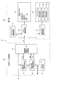
- FIG. 1 is a block diagram illustrating a configuration of the image display apparatus according to the first embodiment.
- the image display device 1 illustrated in FIG. 1 includes an image data conversion unit 10 and a display unit 20.
- the image data conversion unit 10 includes a parameter storage unit 11, a statistical value / saturation calculation unit 12, a distribution ratio / coefficient calculation unit 13, and a drive image data calculation unit 14.
- the display unit 20 includes a timing control circuit 21, a panel drive circuit 22, a backlight drive circuit 23, a liquid crystal panel 24, and a backlight 25.
- the image display device 1 has a function of performing low-luminance part noise countermeasure processing.
- the image display device 1 is a field sequential type liquid crystal display device.
- the image display device 1 divides one frame period into a plurality of subframe periods, and displays subframes of different colors in each subframe period.
- the image display device 1 divides one frame period into four subframe periods, and displays white, blue, green, and red subframes in the first to fourth subframe periods, respectively.
- the white subframe is a common color subframe.
- the image display device 1 receives input image data D1 including red, green, and blue image data.
- the image data converter 10 obtains drive image data D2 corresponding to white, blue, green, and red subframes based on the input image data D1.
- this processing is referred to as “image data conversion processing”
- the driving image data D2 corresponding to the white, blue, green, and red sub-frames are respectively referred to as “white, blue, and blue included in the driving image data D2. , Green and red image data ".
- the display unit 20 displays white, blue, green, and red subframes in one frame period based on the driving image data D2.
- the timing control circuit 21 outputs a timing control signal TC to the panel drive circuit 22 and the backlight drive circuit 23.
- the panel drive circuit 22 drives the liquid crystal panel 24 based on the timing control signal TC and the drive image data D2.
- the backlight drive circuit 23 drives the backlight 25 based on the timing control signal TC.
- the liquid crystal panel 24 includes a plurality of pixels 26 arranged two-dimensionally.
- the backlight 25 includes a red light source 27r, a green light source 27g, and a blue light source 27b.
- the backlight 25 may include a white light source.
- the panel drive circuit 22 drives the liquid crystal panel 24 based on the white image data included in the drive image data D2, and the backlight drive circuit 23 has a red light source 27r, a green light source 27g, and a blue light source. 27b emits light. As a result, a white subframe is displayed.
- the backlight driving circuit 23 may cause the white light source to emit light in the first subframe period.
- the panel drive circuit 22 drives the liquid crystal panel 24 based on the blue image data included in the drive image data D2, and the backlight drive circuit 23 causes the blue light source 27b to emit light. Thereby, the blue subframe is displayed.
- the panel drive circuit 22 drives the liquid crystal panel 24 based on the green image data included in the drive image data D2, and the backlight drive circuit 23 causes the green light source 27g to emit light. Thereby, a green subframe is displayed.
- the panel drive circuit 22 drives the liquid crystal panel 24 based on the red image data included in the drive image data D2, and the backlight drive circuit 23 causes the red light source 27r to emit light. Thereby, the red subframe is displayed.
- the red, green, and blue image data included in the input image data D1 is luminance data normalized to a value between 0 and 1.
- the pixel 26 is achromatic.
- the white, blue, green, and red image data included in the drive image data D2 is also luminance data normalized to a value of 0 or more and 1 or less.
- the white image data (value distributed to the common color subframe) included in the drive image data D2 is 0 or more and the minimum value of the three colors of image data included in the input image data D1 It is determined within the following range.
- the distribution ratio WRs is the ratio of white image data to the maximum value (minimum value of three-color image data) that can be obtained by white image data, obtained for each pixel. For example, when the distribution ratio WRs is determined to be 0.6 when the red image data included in the input image data D1 is 0.5 and the green and blue image data is 1, the white image included in the drive image data D2 The data will be 0.3.
- the parameter storage unit 11 stores parameters WRX, RA, RB, WBR, and NR used in the image data conversion process.
- the statistical value / saturation calculator 12 obtains the maximum value Dmax, the minimum value Dmin, and the saturation S for each pixel based on the input image data D1. Since the maximum value Dmax is equal to the brightness V in the HSV color space, the maximum value Dmax is described as the brightness V in the following description.
- the distribution ratio / coefficient calculator 13 obtains the distribution ratio WRs and the coefficient Ks used in the amplification compression process based on the lightness V, the saturation S, and the parameters WRX, RA, RB, WBR, and NR (details will be described later).
- the drive image data calculation unit 14 obtains drive image data D2 based on the input image data D1, the minimum value Dmin, the distribution ratio WRs, the coefficient Ks, and the parameter WBR.
- the parameter NR indicates whether or not the low luminance part noise countermeasure process is performed, and takes a value of 0 or 1. A value of 0 indicates that the low luminance part noise countermeasure process is not performed, and a value of 1 indicates that the low luminance part noise countermeasure process is performed.
- the parameter WRX is a parameter corresponding to the response characteristic of the pixel 26 included in the display unit 20. The parameter WRX is included in the calculation formula for obtaining the distribution ratio WRs.
- the minimum value in one frame period of the drive image data D2 is DDmin, and the maximum value is DDmax.
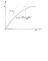
- the distribution ratio / coefficient calculation unit 13 determines the coefficient Ks so as to satisfy the following expression (1) according to the parameters RA and RB stored in the parameter storage unit 11.
- the range satisfying the formula (1) is a hatched portion shown in FIG.
- the parameters RA and RB designate the range of the maximum value DDmax according to the minimum value DDmin.
- the parameter WBR specifies the luminance of the light source 27 included in the backlight 25 when displaying the white subframe.
- the parameter WBR takes a value in the range of 0 ⁇ WBR ⁇ 1.
- the display unit 20 controls the luminance of the light source 27 according to the parameter WBR when displaying the white subframe. More specifically, the backlight drive circuit 23 in the display unit 20 determines the brightness of the light source 27 when displaying the white subframe and the brightness WBR of the light source 27 when displaying other subframes according to the parameter WBR. Control twice.
- FIG. 3 is a flowchart of the image data conversion process. The process shown in FIG. 3 is performed on the data of each pixel included in the input image data D1.
- red, green, and blue image data of a certain pixel included in the input image data D1 are Ri, Gi, Bi, and white, blue, green, and red of the pixel included in the drive image data D2, respectively.
- These image data are Wd, Bd, Gd, and Rd, respectively, and processing for the three color image data Ri, Gi, and Bi will be described.
- the image data converter 10 receives the three color image data Ri, Gi, Bi (step S101).
- the statistical value / saturation calculator 12 obtains the lightness V and the minimum value Dmin for the three-color image data Ri, Gi, Bi (step S102).
- the statistical value / saturation calculator 12 obtains the saturation S according to the following equation (2) based on the lightness V and the minimum value Dmin (step S103).
- S (V ⁇ Dmin) / V (2)
- the distribution ratio / coefficient calculation unit 13 obtains the distribution ratio WRs according to the calculation formula described later based on the saturation S and the parameters WRX and WBR (step S104).
- the distribution ratio / coefficient calculator 13 obtains a coefficient Ks according to a calculation formula described later based on the saturation S and the parameters WRX, RA, RB, and WBR (step S105).
- the distribution ratio / coefficient calculator 13 determines the distribution ratio WRs in step S104 and then determines the coefficient Ks in step S105, the distribution ratio WRs is used and the input image data D1 takes the lightness V of the input image data D1.
- the maximum value that the coefficient Ks can take under the condition that the maximum value 1 is obtained is obtained.
- the distribution ratio / coefficient calculator 13 performs conditional branching according to the parameter NR (step S106).
- the distribution ratio / coefficient calculation unit 13 obtains a value NS based on the coefficient Ks and the parameter WBR (step S107), obtains a coefficient Ksv based on the lightness V, the coefficient Ks, and the value NS (step S108), and the coefficient Ksv. Is a coefficient Ks (step S109).
- the drive image data calculation unit 14 uses the following equations (3a) to (3d) based on the three color image data Ri, Gi, Bi, the minimum value Dmin, the distribution ratio WRs, the coefficient Ks, and the parameter WBR. Accordingly, four color image data Wd, Bd, Gd, and Rd are obtained (step S110).
- Four-color image data Wd, Bd, Gd, and Rd are obtained using Ksv.
- Saturation S and distribution ratio WRs take values of 0 or more and 1 or less.
- the maximum value of the blue, green, and red image data Bd, Gd, and Rd included in the drive image data D2 is Ddmax, and the minimum value is Ddmin.
- PP 1, Wd, Ddmax, and Ddmin are given by the following equations (4a) to (4c), respectively.
- FIG. 4 is a diagram showing the range of the saturation S and the distribution ratio WRs.
- the range of (S, WRs) shown in FIG. 4 is divided into a first area where Ddmin ⁇ Wd ⁇ Ddmax, a second area where Ddmax ⁇ Wd, and a third area where Wd ⁇ Ddmin.
- Ks RB / [1 - ⁇ WRs (1-RA) + RA ⁇ (1-S)] (7)
- the response speed of the pixel 26 changes according to the gradation displayed by the pixel 26 (hereinafter referred to as display gradation).
- display gradation the response speed of the pixel 26 is slower as the display gradation is higher, and the response speed of the pixel 26 is slower as the display gradation is lower.
- the distribution ratio WRs is determined so that (S, WRs) approaches the boundary line between the first and second areas, and the white image data Wd approaches the maximum value Ddmax.
- the distribution ratio WRs is determined so that (S, WRs) approaches the boundary line between the first and third areas, and the white image data Wd approaches the minimum value Ddmin.
- the distribution ratio / coefficient calculation unit 13 calculates the distribution ratio WRs according to the following formula (8), and calculates the coefficient Ks according to the formula (7).
- WBRo WBR / (1 + WBR)
- Ts 3WBRo / 2
- WBRx 3WBR / ⁇ 2WRX (1 + WBR) ⁇ .
- the parameters RA, RB, and WBR take values within the ranges of 0 ⁇ RA ⁇ 1, 0 ⁇ RB ⁇ 1, and 0 ⁇ WBR ⁇ 1.
- the parameter WRX takes a value within the range of WBRo ⁇ WRX ⁇ 1.
- RB 1 ⁇ RA.
- the function for obtaining the coefficient Ks is expressed using the distribution ratio WRs.
- the function for obtaining the coefficient Ks is a function based on the saturation S.
- FIG. 5 is a graph showing a distribution ratio WRs.
- RA 0.25
- RB 0.75
- the latter function is determined so that the graph of the former function and the graph of the latter function touch at a point (1-WBRx, 2WRX / 3).
- the parameter WRX is set to a value close to 1 and the white image data Wd is brought closer to the maximum value Ddmax.
- the parameter WRX is set to a value closer to WBRo, and the white image data Wd is brought closer to the minimum value Ddmin.
- the function for obtaining the distribution ratio WRs and the function for obtaining the coefficient Ks change smoothly in the range of 0 ⁇ S ⁇ 1. Therefore, it is possible to prevent image distortion when displaying a gradation image.
- NR 1
- the distribution ratio / coefficient calculator 13 obtains a value NS according to the following equation (9) in step S107, and obtains a coefficient Ksv according to the following equation (10) in step S108.
- NB (1 + WBR) 2 / ⁇ 2 (1 + WBR) ⁇ 1 ⁇ .
- FIG. 7 is a graph showing the coefficient Ksv.
- the smaller the lightness V the smaller the difference between the minimum value and the maximum value of the coefficient Ksv. Therefore, when the lightness V is small, the change amount of the coefficient Ksv with respect to the change amount of the saturation S becomes small. Therefore, by performing low-luminance part noise countermeasure processing, it is possible to prevent the pixel color from changing greatly between adjacent pixels when the luminance is low, and to suppress noise generated in the low-luminance part of the display image. it can.
- the saturation S and the hue H are the same, the larger the input image data D 1, the higher the luminance of the pixel 26 (that is, to maintain the gradation).
- the following equation (11) is derived from Ksv ⁇ V ⁇ Ks. Ksv ⁇ Ks / V (11)
- Equation (11) The range satisfying Equation (11) is the shaded area shown in FIG.
- the function for determining the coefficient Ksv is determined based on the lightness V so that the function graph is within the shaded area shown in FIG.
- the distribution ratio / coefficient calculator 13 calculates the coefficient Ksv according to the equation (10). As shown in FIG. 8, the coefficient Ksv graph passes through two points (0, NS) and (1, Ks).
- Equation (12) is derived from Ks ⁇ NS ⁇ ⁇ Ks.
- a range satisfying the equation (12) is a dot pattern portion shown in FIG. NS ⁇ 2Ks (12)
- FIG. 10 is a diagram showing a graph of the value NS.
- the graph shown in FIG. 10 passes through three points (0, 0), (1, 1), and (1 + WBR, NB).
- FIG. 11 is a diagram illustrating a graph of coefficients in the image display apparatus 1.
- the red, green, and blue image data included in the input image data D1 is (0.25, 0.25, 0.25), and (0.25, 0.25, 0.2) (hereinafter, the former is referred to as data Da and the latter is referred to as data Db).
- the difference between the result of performing the amplification compression process on the data Da and the result of performing the amplification compression process on the data Db is the low luminance part noise countermeasure process. It is smaller than the case without it.
- the driving image data calculation unit 14 calculates the expression (3a) based on the three-color image data Ri, Gi, Bi, the minimum value Dmin, the distribution ratio WRs, the coefficient Ks, and the parameter WBR.
- the color represented by the three color image data Ri, Gi, Bi is referred to as the color before conversion
- the color represented by the four color image data Wd, Bd, Gd, Rd is referred to as the color after conversion.
- the image data conversion processing in the image data conversion unit 10 maintains the same value of the hue H and the saturation S in the HSV color space between the input image data D1 and the driving image data D2 for each pixel.
- the image display device 1 generates a common color subframe (white subframe) based on the input image data D1 corresponding to a plurality of color components (red, green, and blue).
- An image data conversion unit 10 that obtains drive image data D2 corresponding to a plurality of subframes (white, blue, green, and red subframes), and a plurality of subframes in one frame period based on the drive image data D2
- This is a field sequential image display device including a display unit 20 for displaying a frame.
- the image data conversion unit 10 converts a first image data (input image data D1) corresponding to a plurality of color components into second image data (driving image data D2) corresponding to a plurality of subframes (images). Data conversion processing) is performed for each pixel 26. In the conversion process, the hue H and the saturation S in the HSV color space are kept at the same value between the first image data and the second image data for each pixel 26.
- the image data converter 10 calculates a coefficient Ks used in the conversion process, and performs the conversion process using the coefficient Ks.
- the gradation property can be maintained by obtaining the coefficient Ks that varies depending on the lightness V, and the lightness V after the amplification and compression processing increases as the lightness V increases when the saturation S is the same.
- the amount of change in the coefficient Ks with respect to the amount of change in the saturation S can be reduced to suppress noise generated in the low-luminance portion of the display image. Therefore, according to the image display device 1 according to the present embodiment, it is possible to suppress noise generated in the low luminance portion of the display image while maintaining the gradation.
- the image data conversion unit 10 obtains a distribution ratio WRs indicating a value distributed to the common color subframe and a coefficient Ks used in the amplification compression process, performs a conversion process using the distribution ratio WRs and the coefficient Ks, Based on the saturation S, the distribution ratio WRs is set so that the second image data corresponding to the common color subframe falls within the range from the minimum value to the maximum value of the second image data corresponding to the other subframes. Ask. Thereby, the change of the image data after conversion within 1 frame period can be suppressed, and color reproducibility can be made high. Further, the image data converter 10 obtains the distribution ratio WRs and the coefficient Ks according to a function that smoothly changes according to the saturation S. Thereby, the disturbance of the image when displaying the gradation image can be prevented.
- the range of the maximum value within one frame period of the second image data is determined according to the minimum value within one frame period of the second image data. Thereby, the change of the image data after conversion within 1 frame period can be suppressed, and color reproducibility can be made high. Further, the image data conversion unit 10 obtains a larger distribution ratio WRs for each pixel as the saturation S increases. As a result, the larger the saturation S, the larger the ratio of the values distributed to the common color subframe, and the color breakup can be suppressed.
- the display unit 20 includes a light source 27 and controls the luminance of the light source 27 when displaying a common color subframe. Therefore, according to the image display device 1, the heat generated by the light source 27 can be reduced.
- the image data conversion unit 10 includes a parameter storage unit 11 that stores parameters used in the conversion process.
- the parameter storage unit 11 includes a first parameter (parameter WRX) corresponding to the response characteristics of the pixels 26 included in the display unit 60. ) Is memorized. Thereby, a suitable first parameter can be set according to the response characteristic of the display unit 20 to improve color reproducibility.
- the parameter storage unit 11 includes a range of the maximum value DDmax within one frame period of the second image data according to the minimum value DDmin within one frame period of the second image data.
- the second parameters (parameters RA and RB) for designating are stored.
- a suitable first parameter is set according to the response characteristic of the display unit 20, and one frame period of the driving image data D2 is set according to the minimum value DDmin within one frame period of the driving image data D2 using the second parameter.
- the parameter storage unit 11 also includes a light source included in the display unit 20 when displaying a common color subframe (white subframe) in addition to the first parameter (parameter WRX) and the second parameter (parameters RA and RB).
- a third parameter (parameter WBR) for designating 27 luminances is stored.
- the display unit 20 controls the luminance of the light source 27 according to the third parameter when displaying the common color subframe. Therefore, according to the image display device 1, the first and second parameters are used to improve color reproducibility, and the third parameter is used to control the luminance of the light source 27 when displaying the common color subframe. The heat generated by the light source 27 can be reduced.
- the image data conversion unit 10 performs a conversion process on the normalized luminance data (input image data D1). Thereby, the conversion process can be performed correctly.
- the input image data D1 corresponds to red, green, and blue
- the driving image data D2 corresponds to red, green, blue, and white subframes
- the common color subframe is a white subframe. . Therefore, in an image display device that displays sub-frames of three primary colors and white based on input image data corresponding to the three primary colors, noise generated in a low-luminance portion of the display image is suppressed while maintaining gradation. Can do.
- the image display apparatus according to the second embodiment has the same configuration as the image display apparatus 1 according to the first embodiment (see FIG. 1).
- the image display apparatus according to the present embodiment has a function of obtaining the value NS according to a calculation formula other than the formula (9) when performing the low luminance part noise countermeasure process.
- differences from the first embodiment will be described.
- the parameter NR takes a value of 0, 1, 2, or 3.
- a value of 0 indicates that low-luminance part noise countermeasure processing is not performed, and values 1 to 3 indicate that low-luminance part noise countermeasure processing is performed by the first to third methods, respectively.
- FIG. 14 is a flowchart of image data conversion processing according to the present embodiment.
- the flowchart shown in FIG. 14 is obtained by replacing steps S106 and S107 with steps S201 and S202 in the flowchart shown in FIG.
- the image data conversion unit 10 operates in the same manner as in the first embodiment in steps S101 to S105.
- the distribution ratio / coefficient calculator 13 performs conditional branching according to the parameter NR (step S201).
- the distribution ratio / coefficient calculation unit 13 obtains a value NS according to the NR-th calculation formula based on the coefficient Ks and the parameters WBR and NR (step S202).
- the value NS is obtained according to the following equation (14).
- the graph shown in FIG. 15 passes through two points (0, 0) and (1, 1), and the graph shown in FIG. 16 passes through two points (0, 0) and (0.75, 0.75).
- the following formula (15) is considered as a calculation formula for obtaining the value NS based on the coefficient Ks.
- the parameter storage unit 11 stores the parameter NR, and the value included in the equation for obtaining the value NS changes according to the value of the parameter NR.
- the parameter storage unit may store the values NB and NC as parameters, and the distribution ratio / coefficient calculation unit may obtain the value Ks according to the equation (15).
- the image display apparatus according to the third embodiment has the same configuration as the image display apparatus 1 according to the first embodiment (see FIG. 1).
- the image display apparatus according to the present embodiment has a function of obtaining the coefficient Ksv according to a calculation formula other than the formula (10) when performing the low luminance part noise countermeasure process.
- the parameter NR takes any value of 0, 1, 2, 3 or 4.
- a value of 0 indicates that low-luminance part noise countermeasure processing is not performed, and values 1 to 4 indicate that low-luminance part noise countermeasure processing is performed by the first to fourth methods, respectively.
- the parameter storage unit 11 stores the parameter NE in addition to the parameters WRX, RA, RB, WBR, and NR.
- FIG. 17 is a flowchart of image data conversion processing according to the present embodiment.
- the flowchart shown in FIG. 17 is obtained by replacing step S201 with step S301 and adding steps S302 and S303 to the flowchart shown in FIG.
- the image data converter 10 operates in the same manner as in the first and second embodiments in steps S101 to S105.
- the distribution ratio / coefficient calculator 13 performs conditional branching according to the parameter NR (step S301).
- the distribution ratio / coefficient calculator 13 sets the value NS to the fixed value NSc (step S302), obtains the coefficient Ksv according to a calculation formula different from step S108 (step S303), and proceeds to step S109. move on.
- the distribution ratio / coefficient calculator 13 preferably sets the value NS to 1.
- the distribution ratio / coefficient calculator 13 obtains the coefficient Ksv according to the following equation (16).
- FIG. 19 is a block diagram illustrating a configuration of an image display apparatus according to the fourth embodiment.
- the image display device 3 illustrated in FIG. 19 includes an image data conversion unit 30 and a display unit 40.
- the image data conversion unit 30 includes a parameter storage unit 31, a statistical value / saturation calculation unit 12, a distribution ratio / coefficient calculation unit 32, and a drive image data calculation unit 33.
- the display unit 40 is obtained by replacing the backlight drive circuit 23 with the backlight drive circuit 41 in the display unit 20 according to the first embodiment.
- the luminance of the light source 27 included in the backlight 25 is fixed.
- the parameter storage unit 31 stores parameters WRX, RA, RB, and NR used in the image data conversion process, and does not store the parameter WBR.
- the display image in the case where the luminance of the light source 27 included in the backlight 25 is not controlled, the display image can be reduced while maintaining the gradation as in the first embodiment. Noise generated in the luminance part can be suppressed.
- the image display apparatus according to the fifth embodiment has the same configuration as the image display apparatus 1 according to the first embodiment (see FIG. 1).
- the image display apparatus according to the present embodiment selectively performs the high luminance portion noise countermeasure processing in addition to the low luminance portion noise countermeasure processing.
- the parameter storage unit 11 stores parameters GL and RC in addition to the parameters WRX, RA, RB, WBR, and NR.
- the distribution ratio / coefficient calculator 13 obtains the coefficient Ks according to a calculation formula different from that of the first embodiment when performing the high luminance part noise countermeasure process.
- the parameter GL indicates the type of high luminance part noise countermeasure processing, and takes a value of 0, 1, or 2.
- a value of 0 indicates that no high luminance portion noise countermeasure processing is performed, and a value of 1 or 2 indicates that the high luminance portion noise countermeasure processing is performed.
- the parameter RC is included in the calculation formula for obtaining the coefficient Ks when the high luminance part noise countermeasure process is performed.
- the parameter RC takes a value in the range of 0 ⁇ RC ⁇ 1.
- FIG. 20 is a flowchart of image data conversion processing according to the present embodiment.
- the flowchart shown in FIG. 20 is obtained by adding steps S301 to S304 to the flowchart shown in FIG.
- the image data conversion unit 10 operates in the same manner as in the first embodiment in steps S101 to S104.
- the distribution ratio / coefficient calculation unit 13 performs conditional branching according to the parameter GL (step S301).
- the distribution ratio / coefficient calculator 32 calculates the coefficient Ks according to the equation (7) (step S105).
- the distribution ratio / coefficient calculator 13 obtains the coefficient Ks ′ according to the following equation (17a).
- the correction coefficient Kh increases as the saturation S decreases.
- the distribution ratio / coefficient calculator 13 outputs the result of multiplying the coefficient Ks ′ by the correction coefficient Kh as the coefficient Ks (step S304).
- FIG. 21 is a diagram illustrating a graph of the coefficient Ks obtained by the processing up to step S106.
- RB 0.35
- the image data conversion unit 10 determines the distribution ratio WRs, the temporary coefficient Ks ′, and the saturation for each pixel based on the saturation S.
- FIG. 22 is a block diagram illustrating a configuration of an image display apparatus according to the sixth embodiment.
- the image display device 5 illustrated in FIG. 22 includes an image data conversion unit 50 and a display unit 60.
- the image data conversion unit 50 is obtained by adding a parameter selection unit 52 to the image data conversion unit 10 according to the fifth embodiment and replacing the parameter storage unit 11 with a parameter storage unit 51.
- the display unit 60 is obtained by adding a temperature sensor 61 to the display unit 20 according to the fifth embodiment.
- differences from the fifth embodiment will be described.
- the temperature sensor 61 is included in the display unit 60 and measures the temperature T of the display unit 60.
- the temperature sensor 61 is provided in the vicinity of the liquid crystal panel 24, for example.
- the temperature T measured by the temperature sensor 61 is input to the parameter selection unit 52.
- the parameter storage unit 51 stores a plurality of values according to the temperature for the parameters WRX, RA, RB, WBR, NR, and GL.
- the parameter selection unit 52 selects a value corresponding to the temperature T measured by the temperature sensor 61 from a plurality of values stored in the parameter storage unit 51, and selects the selected value as a parameter WRX, RA, RB, WBR, Output as NR and GL.
- the parameters WRX, RA, RB, WBR, NR, and GL output from the parameter selection unit 52 are input to the distribution ratio / coefficient calculation unit 13 and the backlight drive circuit 23.
- the image data conversion unit 50 stores the parameters WRX, RA, RB, WBR, and NR used in the conversion process (image data conversion process).
- the display unit 60 includes a temperature sensor 61.
- the parameter storage unit 51 stores a plurality of values for the parameters WRX, RA, RB, WBR, NR, and GL according to the temperature, and the image data conversion unit 50 selects the temperature from among the plurality of values stored in the parameter storage unit 51. A value corresponding to the temperature T measured by the sensor 61 is selected and used in the conversion process.
- the image display device 5 by performing the conversion process based on the parameters WRX, RA, RB, WBR, NR, and GL corresponding to the temperature T of the display unit 60, the response characteristic of the display unit 60 depends on the temperature. The color reproducibility can be improved even when changing.
- FIG. 23 is a block diagram illustrating a configuration of an image display apparatus according to the seventh embodiment.
- An image display device 7 illustrated in FIG. 23 includes an image data conversion unit 70 and a display unit 60.
- the image data conversion unit 70 is obtained by adding a frame memory 71 to the image data conversion unit 50 according to the sixth embodiment and replacing the statistical value / saturation calculation unit 12 with a statistical value / saturation calculation unit 72. .
- differences from the sixth embodiment will be described.
- the input image data D1 including red, green, and blue image data is input to the image display device 7.
- the frame memory 71 stores input image data D1 for one frame or a plurality of frames.
- the statistical value / saturation calculation unit 72 obtains the minimum value Dmin, brightness V, and saturation S for each pixel based on the input image data D1. At this time, the statistical value / saturation calculator 72 obtains the minimum value Dmin, brightness V, and saturation S based on the input image data D1 corresponding to the plurality of pixels stored in the frame memory 71 for each pixel.
- the statistical value / saturation calculation unit 72 calculates the saturation for a plurality of neighboring pixels, and calculates the average value, the maximum value, or the minimum value of the determined plurality of saturations. A value may be obtained. Further, the statistical value / saturation calculation unit 72 may perform calculation by weighting the saturation of neighboring pixels according to the distance between the neighboring pixels and the like. Thereby, by changing the saturation S smoothly in the spatial direction or by suppressing the magnitude of the coefficient Ks according to the saturation S, reducing the uncomfortable feeling of the image due to the luminance difference according to the saturation S. Can do.
- the statistical value / saturation calculation unit 72 may calculate the saturation S by applying a filter calculation to the saturation obtained for the past frame and the saturation obtained for the current frame. Further, the statistical value / saturation calculation unit 72 may perform calculation by weighting the saturation of the past frame according to a time difference from the current frame. Thereby, by changing the saturation S smoothly in the time direction, or by suppressing the magnitude of the coefficient Ks corresponding to the saturation S, an uncomfortable feeling of the image due to the luminance difference in the time direction corresponding to the saturation S can be realized. Can be reduced.
- the statistical value / saturation calculator 72 obtains the minimum value Dmin and the lightness V by the same method.
- the image data conversion unit 70 includes the frame memory 71 that stores the first image data (input image data D1), and each pixel is stored in the frame memory 71. Conversion processing is performed based on the first image data corresponding to the plurality of stored pixels. Therefore, according to the image display device 7, it is possible to prevent a rapid change in the distribution ratio WRs and the coefficient Ks, and to prevent the color of the pixel 26 from changing rapidly in the spatial direction or the time direction.
- FIG. 24 is a block diagram illustrating a configuration of an image display device according to a modification of the first embodiment.
- the image data conversion unit 80 is different from the image data conversion unit 10 according to the first embodiment in that an inverse gamma conversion unit 81, a gamma conversion unit 82, and a response compensation processing unit. 83 is added.
- the input image data D1 input to the image display device 8 is gradation data before performing inverse gamma conversion.
- the inverse gamma conversion unit 81 performs inverse gamma conversion on the input image data D1 to obtain image data D3 after the inverse gamma conversion.
- the parameter storage unit 11, the statistical value / saturation calculation unit 12, the distribution ratio / coefficient calculation unit 13, and the drive image data calculation unit 14 are the same as those in the first embodiment for the image data D3 after inverse gamma conversion. Similar processing is performed. Thereby, image data D4 before gamma conversion is obtained.
- the gamma conversion unit 82 obtains image data D5 by performing gamma conversion on the image data D4 before gamma conversion.
- the response compensation processing unit 83 obtains drive image data D2 by performing response compensation processing on the image data D5.
- the response compensation processing unit 83 performs overdrive processing (also referred to as overshoot processing) that compensates for insufficient response speed of the pixels 26.
- the image data conversion unit 80 converts the first image data corresponding to the plurality of color components (image data D3 after inverse gamma conversion) to the second image corresponding to the plurality of subframes.
- a conversion process (image data conversion process) for converting data (image data D4 before gamma conversion) is performed for each pixel, and a response compensation process is performed on the image data D5 after the conversion process, thereby driving Image data D2 is obtained. Therefore, according to the image display device 8, a desired image can be displayed even when the response speed of the display unit 60 is slow.
- the image data conversion unit 80 includes an inverse gamma conversion unit 81, a gamma conversion unit 82, and a response compensation processing unit 83.
- the image data conversion unit includes an inverse gamma conversion unit 81 and a gamma conversion unit 82, and may not include the response compensation processing unit 83.
- the image data conversion unit includes the response compensation processing unit 83, and includes an inverse gamma conversion unit. 81 and the gamma conversion unit 82 may not be included.
- at least one of the inverse gamma conversion unit 81, the gamma conversion unit 82, and the response compensation processing unit 83 may be added to the image data conversion units according to the second to fifth embodiments.
- gamma conversion may be performed after the response compensation process. In this case, response compensation processing is performed on the image data output from the driving image data calculation unit, and gamma conversion is performed on the image data after the response compensation processing.
- the boundary of the limited range shown in FIG. 2 is a straight line, but the boundary of the limited range is a curve that is realized as a limited range as a result when high brightness noise countermeasures are implemented in the fifth to seventh embodiments. Alternatively, it may be a broken line having a bending point. However, the boundary of the limited range is preferably a straight line or a curve.
- the image display device for obtaining the distribution ratio WRs and the coefficients Ks and Ksv according to a specific calculation formula has been described.
- the calculation formulas for obtaining the distribution ratio WRs and the coefficients Ks and Ksv are as follows. Other than those described in the embodiment may be used.
- a conventionally known calculation formula may be used as a calculation formula for obtaining the distribution ratio WRs, and any calculation formula satisfying formula (11) may be used as a calculation formula for obtaining the coefficient Ksv.
- a field sequential type image display device other than the liquid crystal display device, a see-through image display device having a function of showing through the back of the display panel, and the like can be configured.
- the field sequential image display device performs image data conversion for obtaining driving image data corresponding to a plurality of subframes including a common color subframe based on input image data corresponding to a plurality of color components. And a display unit that displays the plurality of sub-frames in one frame period based on the driving image data.
- the image data conversion unit performs a conversion process for converting each of the first image data corresponding to the plurality of color components into second image data corresponding to the plurality of subframes.
- the hue and saturation in the HSV color space are kept at the same value between the first image data and the second image data, and the image data conversion unit calculates a coefficient used in the conversion process, and the coefficient The coefficient is different depending on the lightness, and if the saturation is the same, the coefficient is a value such that the lightness after the conversion processing increases as the lightness increases. The smaller the value, the smaller the difference between the minimum value and the maximum value of the coefficient (the eleventh aspect).
- the image data conversion unit obtains a distribution ratio indicating a value to be distributed to the common color subframe and the coefficient used in the amplification compression process, performs the conversion process using the distribution ratio and the coefficient, The distribution is performed so that the second image data corresponding to the common color subframe falls within a range from a minimum value to a maximum value of the second image data corresponding to another subframe based on the saturation.
- a ratio may be obtained (second aspect).
- the image data conversion unit may obtain the distribution ratio and the coefficient according to a function that smoothly changes according to saturation (third aspect). In the conversion process, the range of the maximum value within one frame period of the second image data may be determined according to the minimum value within one frame period of the second image data (fourth aspect).
- the display unit may include a light source, and may control luminance of the light source when displaying the common color subframe (fifth aspect).
- the image data conversion unit obtains, for each pixel, the distribution ratio, a provisional coefficient, and a smaller correction coefficient as the saturation is larger, based on the saturation, and multiplies the provisional coefficient by the correction coefficient.
- the coefficient may be obtained (sixth aspect).
- the display unit may include a light source, and may control luminance of the light source when displaying the common color subframe (seventh aspect).
- the image data conversion unit may obtain a larger distribution ratio for each pixel as the saturation is larger (eighth aspect).
- the range of the maximum value within one frame period of the second image data may be determined according to the minimum value within one frame period of the second image data (ninth aspect).
- the display unit may include a light source, and may control luminance of the light source when displaying the common color subframe (tenth aspect).
- the image data conversion unit obtains, for each pixel, the distribution ratio, a provisional coefficient, and a smaller correction coefficient as the saturation is larger, based on the saturation, and multiplies the provisional coefficient by the correction coefficient. You may obtain
- the display unit may include a light source, and may control luminance of the light source when displaying the common color subframe (a twelfth aspect).
- the image data conversion unit may include a parameter storage unit that stores parameters used in the conversion process, and the parameter storage unit may store a first parameter corresponding to a response characteristic of a pixel included in the display unit.
- the parameter storage unit may further store a second parameter that specifies a range of a maximum value within one frame period of the second image data according to a minimum value within one frame period of the second image data.
- the parameter storage unit further stores a third parameter that specifies luminance of a light source included in the display unit when the common color subframe is displayed, and the display unit displays the common color subframe. Sometimes, the luminance of the light source may be controlled according to the third parameter (fifteenth aspect).
- the image data conversion unit includes a parameter storage unit that stores parameters used in the conversion process, the display unit includes a temperature sensor, and the parameter storage unit stores a plurality of values for the parameters according to temperature.
- the image data conversion unit may select a value corresponding to the temperature measured by the temperature sensor from among a plurality of values stored in the parameter storage unit and use it in the conversion process (a sixteenth aspect). aspect).
- the image data conversion unit includes a frame memory for storing the first image data, and for each pixel, the conversion process may be performed based on the first image data corresponding to a plurality of pixels stored in the frame memory. Good (17th aspect).
- the image data conversion unit may perform the conversion process on the normalized luminance data (eighteenth aspect).
- the image data conversion unit may obtain the drive image data by performing a response compensation process on the image data after the conversion process (19th aspect).
- the input image data corresponds to red, green, and blue
- the drive image data corresponds to red, green, blue, and white subframes
- the common color subframe is a white subframe. (20th aspect).
- the field sequential image display method includes an image data conversion step for obtaining drive image data corresponding to a plurality of subframes including a common color subframe based on input image data corresponding to a plurality of color components; A display step of displaying the plurality of sub-frames in one frame period based on the driving image data, wherein the image data conversion step converts the first image data corresponding to the plurality of color components into the plurality of sub-frames.
- a conversion process for converting into corresponding second image data is performed for each pixel, and the conversion process calculates the hue and saturation in the HSV color space between the first image data and the second image data for each pixel.
- the image data conversion step calculates a coefficient used in the conversion process, and uses the coefficient
- the conversion coefficient is different depending on the lightness, the value is such that the greater the lightness, the greater the lightness after the conversion process if the saturation is the same, the smaller the lightness, The difference between the minimum value and the maximum value of the coefficients may be small (21st aspect).
- the gradation is maintained by obtaining a coefficient that varies depending on the lightness, and that the lightness after conversion processing increases as the lightness increases if the saturation is the same. be able to. Also, by reducing the difference between the minimum and maximum values of the coefficient as the lightness is small, the amount of change in the coefficient relative to the amount of change in saturation is reduced when the lightness is small, and noise generated in the low-luminance part of the display image Can be suppressed. Therefore, it is possible to suppress noise generated in the low luminance portion of the display image while maintaining the gradation.
- the distribution ratio is calculated so that the second image data corresponding to the common color subframe falls within the range from the minimum value to the maximum value of the second image data corresponding to the other subframe.
- the distribution ratio and coefficient according to a function that smoothly changes according to the saturation it is possible to prevent image disturbance when displaying a gradation image.
- heat generated by the light source can be reduced by controlling the luminance of the light source when displaying the common color subframe.
- the distribution ratio, the temporary coefficient, and the smaller the saturation coefficient, the smaller the correction coefficient is obtained, and the result obtained by multiplying the temporary coefficient by the correction coefficient is obtained as the coefficient.
- the noise generated in the high luminance part of the display image can be suppressed together with the noise generated in the low luminance part.
- by obtaining a larger distribution ratio as the saturation increases it is possible to increase the ratio of values distributed to the common color subframe as the saturation increases, thereby suppressing color breakup.
- color reproducibility can be improved by setting a suitable first parameter in accordance with the response characteristic of the display unit.
- color reproducibility is achieved by limiting the maximum value within one frame period of the drive image data according to the minimum value within one frame period of the drive image data using the second parameter. Can be high.
- the heat generated by the light source can be reduced by controlling the luminance of the light source when displaying the common color subframe using the third parameter.
- the color reproducibility can be enhanced even when the response characteristic of the display unit changes according to the temperature.
- the seventeenth aspect by performing the conversion process based on the first image data corresponding to a plurality of pixels, it is possible to prevent the pixel color from changing rapidly in the spatial direction or the time direction.
- the conversion process can be correctly performed by performing the conversion process on the normalized luminance data.
- the nineteenth aspect by performing the response compensation process on the image data after the conversion process, a desired image can be displayed even when the response speed of the display unit is slow.
- the twentieth aspect in an image display device that displays sub-frames of the three primary colors and white based on input image data corresponding to the three primary colors, the image is generated in a low-luminance portion of the display image while maintaining gradation. Noise can be suppressed.
Landscapes
- Engineering & Computer Science (AREA)
- Physics & Mathematics (AREA)
- Computer Hardware Design (AREA)
- General Physics & Mathematics (AREA)
- Theoretical Computer Science (AREA)
- Chemical & Material Sciences (AREA)
- Crystallography & Structural Chemistry (AREA)
- Multimedia (AREA)
- Signal Processing (AREA)
- Control Of Indicators Other Than Cathode Ray Tubes (AREA)
- Liquid Crystal Display Device Control (AREA)
Abstract
Description
本発明は、画像表示装置に関し、より詳細には、フィールドシーケンシャル方式の画像表示装置および画像表示方法に関する。 The present invention relates to an image display device, and more particularly to a field sequential image display device and an image display method.
従来から、1フレーム期間に複数のサブフレームを表示するフィールドシーケンシャル方式の画像表示装置が知られている。例えば、典型的なフィールドシーケンシャル方式の画像表示装置は、赤、緑、および、青の光源を含むバックライトを備え、1フレーム期間に赤、緑、および、青のサブフレームを表示する。赤サブフレームを表示するときには、表示パネルは赤画像データに基づき駆動され、赤色光源が発光する。続いて、緑サブフレームと青サブフレームが同様の方法で表示される。時分割で表示された3枚のサブフレームは、観測者の網膜上で残像現象によって合成され、観測者には1枚のカラー画像として認識される。 Conventionally, a field sequential type image display device that displays a plurality of subframes in one frame period is known. For example, a typical field sequential image display apparatus includes a backlight including red, green, and blue light sources, and displays red, green, and blue subframes in one frame period. When displaying the red subframe, the display panel is driven based on the red image data, and the red light source emits light. Subsequently, the green subframe and the blue subframe are displayed in the same manner. The three sub-frames displayed in time division are synthesized by the afterimage phenomenon on the observer's retina and recognized as one color image by the observer.
フィールドシーケンシャル方式の画像表示装置では、観測者の視線が表示画面内を移動したときに、観測者に各サブフレームの色が分離して見えることがある(この現象は、色割れと呼ばれる)。そこで、色割れを抑制するために、赤、緑、および、青のサブフレームに加えて、白のサブフレームを表示する画像表示装置が知られている。また、赤、緑、および、青の画像データを含む入力画像データに基づき赤、緑、青、および、白の画像データを含む駆動用画像データを求めるときに、入力画像データに1以上の係数を乗算する増幅処理を行う画像表示装置が知られている。 In the field sequential image display device, when the observer's line of sight moves in the display screen, the colors of the subframes may appear to be separated by the observer (this phenomenon is called color breakup). Therefore, in order to suppress color breakup, an image display device that displays white subframes in addition to red, green, and blue subframes is known. When obtaining drive image data including red, green, blue, and white image data based on input image data including red, green, and blue image data, the input image data has one or more coefficients. There is known an image display device that performs an amplification process of multiplying.
従来技術として特許文献1および2には、赤、緑、青、および、白のサブ画素を有するフィールドシーケンシャル方式ではない画像表示装置において、赤、緑、および、青の画像データを含む入力画像データに基づき赤、緑、青、および、白の画像データを含む駆動用画像データを求める方法が記載されている。
以下、入力画像データに基づき分配割合と増幅処理で用いる係数を求め、求めた分配割合と係数を用いて駆動用画像データを求めるフィールドシーケンシャル方式の画像表示装置を考える。このような画像表示装置では、例えば、入力画像データの彩度に基づき係数を求める関数を使用することが考えられる。 Hereinafter, a field sequential type image display apparatus that obtains a distribution ratio and a coefficient used in amplification processing based on input image data and obtains drive image data using the obtained distribution ratio and coefficient will be considered. In such an image display device, for example, it is conceivable to use a function for obtaining a coefficient based on the saturation of the input image data.
しかしながら、彩度に基づき係数を求める関数として、彩度の変化量に対して係数の変化量が大きい関数を使用すると、画素の色が隣接画素間で大きく変化するために階調飛びが発生し、本来輝度差が小さく目立たなかった圧縮ノイズ成分などが、特に低輝度の表示階調で目立つようになる。階調飛びが発生する部分は低輝度部に限らないが、以下、このようなノイズを「低輝度部に発生するノイズ」または「低輝度部ノイズ」という。特許文献1および2に記載された方法を用いても、表示画像の低輝度部に発生するノイズを抑制することができない。
However, if a function that has a large coefficient change amount relative to the saturation change amount is used as a function for obtaining the coefficient based on the saturation, a gradation skip occurs because the pixel color changes greatly between adjacent pixels. Compressed noise components, etc., which originally have a small luminance difference and are not noticeable, are particularly noticeable at low luminance display gradations. The portion where the gradation skip occurs is not limited to the low luminance portion, but such noise is hereinafter referred to as “noise generated in the low luminance portion” or “low luminance portion noise”. Even if the methods described in
それ故に、表示画像の低輝度部で発生するノイズを抑制できるフィールドシーケンシャル画像表示装置および画像表示方法を提供することが課題として挙げるれる。 Therefore, it is a problem to provide a field sequential image display device and an image display method capable of suppressing noise generated in a low luminance portion of a display image.
上記の課題は、例えば、以下のようなフィールドシーケンシャル方式の画像表示装置によって解決することができる。画像表示装置は、複数の色成分に対応した入力画像データに基づき、共通色サブフレームを含む複数のサブフレームに対応した駆動用画像データを求める画像データ変換部と、前記駆動用画像データに基づき1フレーム期間に前記複数のサブフレームを表示する表示部とを備え、前記画像データ変換部は、前記複数の色成分に対応した第1画像データを前記複数のサブフレームに対応した第2画像データに変換する変換処理を各画素について行い、前記変換処理は、各画素について、前記第1画像データと前記第2画像データとの間でHSV色空間における色相と彩度を同じ値に保ち、前記画像データ変換部は、前記変換処理で用いる係数を演算し、前記係数を用いて前記変換処理を行い、前記係数は、前記明度に応じて異なり、前記彩度が同じであれば前記明度が大きいほど前記変換処理後の明度が大きくなるような値であり、前記明度が小さいほど、前記係数の最小値と最大値の差が小さい。 The above problem can be solved by, for example, a field sequential image display device as described below. An image display device includes: an image data conversion unit that obtains drive image data corresponding to a plurality of subframes including a common color subframe based on input image data corresponding to a plurality of color components; and an image data conversion unit based on the drive image data. A display unit that displays the plurality of subframes in one frame period, wherein the image data conversion unit converts the first image data corresponding to the plurality of color components into second image data corresponding to the plurality of subframes. Conversion processing is performed for each pixel, and the conversion processing maintains the same hue and saturation in the HSV color space between the first image data and the second image data for each pixel, The image data conversion unit calculates a coefficient used in the conversion process, performs the conversion process using the coefficient, the coefficient varies depending on the lightness, and the saturation is If Flip a value such brightness increases after the conversion as the lightness increases, the more the brightness is small, the difference between the minimum and maximum values of the coefficient is small.
上記の課題は、例えば、以下のようなフィールドシーケンシャル方式の画像表示方法によって解決することができる。画像表示方法は、複数の色成分に対応した入力画像データに基づき、共通色サブフレームを含む複数のサブフレームに対応した駆動用画像データを求める画像データ変換ステップと、前記駆動用画像データに基づき1フレーム期間に前記複数のサブフレームを表示する表示ステップとを備え、前記画像データ変換ステップは、前記複数の色成分に対応した第1画像データを前記複数のサブフレームに対応した第2画像データに変換する変換処理を各画素について行い、前記変換処理は、各画素について、前記第1画像データと前記第2画像データとの間でHSV色空間における色相と彩度を同じ値に保ち、前記画像データ変換ステップは、前記変換処理で用いる係数を演算し、前記係数を用いて前記変換処理を行い、前記係数は、前記明度に応じて異なり、前記彩度が同じであれば前記明度が大きいほど前記変換処理後の明度が大きくなるような値であり、前記明度が小さいほど、前記係数の最小値と最大値の差が小さい。 The above problem can be solved by, for example, the following field sequential image display method. An image display method is based on input image data corresponding to a plurality of color components, an image data conversion step for obtaining driving image data corresponding to a plurality of subframes including a common color subframe, and the driving image data. A display step of displaying the plurality of sub-frames in one frame period, wherein the image data conversion step converts the first image data corresponding to the plurality of color components into second image data corresponding to the plurality of sub-frames. Conversion processing is performed for each pixel, and the conversion processing maintains the same hue and saturation in the HSV color space between the first image data and the second image data for each pixel, In the image data conversion step, a coefficient used in the conversion process is calculated, the conversion process is performed using the coefficient, and the coefficient is added to the brightness. However, if the saturation is the same, the value is such that the greater the lightness, the greater the lightness after the conversion process, and the smaller the lightness, the smaller the difference between the minimum value and the maximum value of the coefficient. .
このようなフィールドシーケンシャル方式の画像表示装置または画像表示方法によれば、明度に応じて異なり、彩度が同じであれば明度が大きいほど変換処理後の明度が大きくなるような係数を求めることにより、階調性を保持することができる。また、明度が小さいほど係数の最小値と最大値の差を小さくすることにより、明度が小さいときには彩度の変化量に対する係数の変化量を小さくして、表示画像の低輝度部に発生するノイズを抑制することができる。したがって、階調性を保持しながら、表示画像の低輝度部に発生するノイズを抑制することができる。 According to such a field sequential image display device or image display method, by obtaining a coefficient that varies depending on the lightness, and that the lightness after conversion processing increases as the lightness increases if the saturation is the same. , Gradation can be maintained. Also, by reducing the difference between the minimum and maximum values of the coefficient as the lightness is small, the amount of change in the coefficient relative to the amount of change in saturation is reduced when the lightness is small, and noise generated in the low-luminance part of the display image Can be suppressed. Therefore, it is possible to suppress noise generated in the low luminance portion of the display image while maintaining the gradation.
以下、図面を参照して各実施形態に係る画像表示装置および画像表示方法について説明する。なお、以下の説明に含まれる「演算」には、「演算器を用いて演算結果を求める」ことに加えて、「演算結果を予めテーブルに記憶しておき、テーブルを引くことにより演算結果を求める」ことが含まれることを予め指摘しておく。 Hereinafter, an image display device and an image display method according to each embodiment will be described with reference to the drawings. The “calculation” included in the following description includes “calculate the calculation result using a calculator” and “store the calculation result in a table in advance and draw the table to obtain the calculation result. It should be pointed out in advance that “request” is included.
(第1の実施形態)
図1は、第1の実施形態に係る画像表示装置の構成を示すブロック図である。図1に示す画像表示装置1は、画像データ変換部10と表示部20を備えている。画像データ変換部10は、パラメータ記憶部11、統計値/彩度演算部12、分配割合/係数演算部13、および、駆動用画像データ演算部14を含んでいる。表示部20は、タイミング制御回路21、パネル駆動回路22、バックライト駆動回路23、液晶パネル24、および、バックライト25を含んでいる。画像表示装置1は、低輝度部ノイズ対策処理を行う機能を有する。
(First embodiment)
FIG. 1 is a block diagram illustrating a configuration of the image display apparatus according to the first embodiment. The
画像表示装置1は、フィールドシーケンシャル方式の液晶表示装置である。画像表示装置1は、1フレーム期間を複数のサブフレーム期間に分割し、各サブフレーム期間において異なる色のサブフレームを表示する。以下、画像表示装置1は、1フレーム期間を4個のサブフレーム期間に分割し、第1~第4サブフレーム期間では白、青、緑、および、赤のサブフレームをそれぞれ表示するものとする。画像表示装置1では、白サブフレームが共通色サブフレームとなる。
The
画像表示装置1には、赤、緑、および、青の画像データを含む入力画像データD1が入力される。画像データ変換部10は、入力画像データD1に基づき、白、青、緑、および、赤のサブフレームに対応した駆動用画像データD2を求める。以下、この処理を「画像データ変換処理」といい、白、青、緑、および、赤のサブフレームに対応した駆動用画像データD2を、それぞれ、「駆動用画像データD2に含まれる白、青、緑、および、赤の画像データ」という。表示部20は、駆動用画像データD2に基づき、1フレーム期間に白、青、緑、および、赤のサブフレームを表示する。
The
タイミング制御回路21は、パネル駆動回路22とバックライト駆動回路23に対してタイミング制御信号TCを出力する。パネル駆動回路22は、タイミング制御信号TCと駆動用画像データD2に基づき液晶パネル24を駆動する。バックライト駆動回路23は、タイミング制御信号TCに基づきバックライト25を駆動する。液晶パネル24は、2次元状に配置された複数の画素26を含んでいる。バックライト25は、赤色光源27r、緑色光源27g、および、青色光源27bを含んでいる。バックライト25は、白色光源を含んでいてもよい。光源27には、例えば、LED(Light Emitting Diode:発光ダイオード)が使用される。
The
第1サブフレーム期間では、パネル駆動回路22は駆動用画像データD2に含まれる白画像データに基づき液晶パネル24を駆動し、バックライト駆動回路23は赤色光源27r、緑色光源27g、および、青色光源27bを発光させる。これにより、白サブフレームが表示される。なお、バックライト25が白色光源を含む場合には、バックライト駆動回路23は第1サブフレーム期間において白色光源を発光させてもよい。
In the first sub-frame period, the
第2サブフレーム期間では、パネル駆動回路22は駆動用画像データD2に含まれる青画像データに基づき液晶パネル24を駆動し、バックライト駆動回路23は青色光源27bを発光させる。これにより、青サブフレームが表示される。第3サブフレーム期間では、パネル駆動回路22は駆動用画像データD2に含まれる緑画像データに基づき液晶パネル24を駆動し、バックライト駆動回路23は緑色光源27gを発光させる。これにより、緑サブフレームが表示される。第4サブフレーム期間では、パネル駆動回路22は駆動用画像データD2に含まれる赤画像データに基づき液晶パネル24を駆動し、バックライト駆動回路23は赤色光源27rを発光させる。これにより、赤サブフレームが表示される。
In the second subframe period, the
以下、画像データ変換部10の詳細を説明する。入力画像データD1に含まれる赤、緑、および、青の画像データは、0以上1以下の値に正規化された輝度データである。3色の画像データが等しいときに、画素26は無彩色になる。駆動用画像データD2に含まれる白、青、緑、および、赤の画像データも、0以上1以下の値に正規化された輝度データである。
Hereinafter, details of the image
画像データ変換処理では、駆動用画像データD2に含まれる白画像データ(共通色サブフレームに分配される値)は、0以上、かつ、入力画像データD1に含まれる3色の画像データの最小値以下の範囲内で決定される。分配割合WRsは、各画素について求めた、白画像データが取り得る最大値(3色の画像データの最小値)に対する白画像データの割合である。例えば、入力画像データD1に含まれる赤画像データが0.5、緑および青の画像データが1のときに分配割合WRsを0.6に決定した場合、駆動用画像データD2に含まれる白画像データは0.3になる。 In the image data conversion process, the white image data (value distributed to the common color subframe) included in the drive image data D2 is 0 or more and the minimum value of the three colors of image data included in the input image data D1 It is determined within the following range. The distribution ratio WRs is the ratio of white image data to the maximum value (minimum value of three-color image data) that can be obtained by white image data, obtained for each pixel. For example, when the distribution ratio WRs is determined to be 0.6 when the red image data included in the input image data D1 is 0.5 and the green and blue image data is 1, the white image included in the drive image data D2 The data will be 0.3.
パラメータ記憶部11は、画像データ変換処理で用いるパラメータWRX、RA、RB、WBR、NRを記憶する。統計値/彩度演算部12は、入力画像データD1に基づき各画素について、最大値Dmaxと最小値Dminと彩度Sを求める。最大値DmaxはHSV色空間における明度Vに等しいので、以下の説明では最大値Dmaxを明度Vと記載する。分配割合/係数演算部13は、明度Vと彩度SとパラメータWRX、RA、RB、WBR、NRに基づき、分配割合WRsと増幅圧縮処理で用いる係数Ksとを求める(詳細は後述)。駆動用画像データ演算部14は、入力画像データD1、最小値Dmin、分配割合WRs、係数Ks、および、パラメータWBRに基づき、駆動用画像データD2を求める。
The
以下、パラメータ記憶部11に記憶されるパラメータについて説明する。パラメータNRは、低輝度部ノイズ対策処理を行うか否かを示し、0または1の値を取る。値0は低輝度部ノイズ対策処理を行わないことを示し、値1は低輝度部ノイズ対策処理を行うことを示す。パラメータWRXは、表示部20に含まれる画素26の応答特性に応じたパラメータである。パラメータWRXは、分配割合WRsを求める計算式に含まれる。
Hereinafter, parameters stored in the
駆動用画像データD2の1フレーム期間内の最小値をDDmin、最大値をDDmaxとする。低輝度部ノイズ対策処理を行わない場合、分配割合/係数演算部13は、パラメータ記憶部11に記憶されたパラメータRA、RBに応じて、次式(1)を満たすように係数Ksを求める。
DDmax≦RA・DDmin+RB …(1)
例えば、RB=1-RAの場合、式(1)を満たす範囲は、図2に示す斜線部になる。このようにパラメータRA、RBは、最小値DDminに応じて最大値DDmaxの範囲を指定する。
The minimum value in one frame period of the drive image data D2 is DDmin, and the maximum value is DDmax. When the low luminance part noise countermeasure process is not performed, the distribution ratio /
DDmax ≦ RA · DDmin + RB (1)
For example, in the case of RB = 1−RA, the range satisfying the formula (1) is a hatched portion shown in FIG. Thus, the parameters RA and RB designate the range of the maximum value DDmax according to the minimum value DDmin.
パラメータWBRは、白サブフレームを表示するときの、バックライト25に含まれる光源27の輝度を指定する。パラメータWBRは、0≦WBR≦1の範囲内の値を取る。表示部20は、白サブフレームを表示するときに、光源27の輝度をパラメータWBRに応じて制御する。より詳細には、表示部20内のバックライト駆動回路23は、パラメータWBRに従い、白サブフレームを表示するときの光源27の輝度を、他のサブフレームを表示するときの光源27の輝度のWBR倍に制御する。
The parameter WBR specifies the luminance of the light source 27 included in the
図3は、画像データ変換処理のフローチャートである。図3に示す処理は、入力画像データD1に含まれる各画素のデータについて行われる。以下、入力画像データD1に含まれるある画素の赤、緑、および、青の画像データをそれぞれRi、Gi、Bi、駆動用画像データD2に含まれる当該画素の白、青、緑、および、赤の画像データをそれぞれWd、Bd、Gd、Rdとし、3色の画像データRi、Gi、Biに対する処理を説明する。 FIG. 3 is a flowchart of the image data conversion process. The process shown in FIG. 3 is performed on the data of each pixel included in the input image data D1. Hereinafter, red, green, and blue image data of a certain pixel included in the input image data D1 are Ri, Gi, Bi, and white, blue, green, and red of the pixel included in the drive image data D2, respectively. These image data are Wd, Bd, Gd, and Rd, respectively, and processing for the three color image data Ri, Gi, and Bi will be described.
図3に示すように、画像データ変換部10には、3色の画像データRi、Gi、Biが入力される(ステップS101)。次に、統計値/彩度演算部12は、3色の画像データRi、Gi、Biについて明度Vと最小値Dminを求める(ステップS102)。次に、統計値/彩度演算部12は、明度Vと最小値Dminに基づき、次式(2)に従い彩度Sを求める(ステップS103)。
S=(V-Dmin)/V …(2)
ただし、式(2)において、V=0のときにはS=0とする。
As shown in FIG. 3, the
S = (V−Dmin) / V (2)
However, in equation (2), when V = 0, S = 0.
次に、分配割合/係数演算部13は、彩度SとパラメータWRX、WBRに基づき、後述する計算式に従い分配割合WRsを求める(ステップS104)。次に、分配割合/係数演算部13は、彩度SとパラメータWRX、RA、RB、WBRに基づき、後述する計算式に従い係数Ksを求める(ステップS105)。分配割合/係数演算部13は、ステップS104で分配割合WRsを求めた後にステップS105で係数Ksを求めるときには、分配割合WRsを用い、かつ、入力画像データD1の明度Vを入力画像データD1が取り得る最大値1とする条件下で係数Ksが取り得る最大値を求める。
Next, the distribution ratio /
次に、分配割合/係数演算部13は、パラメータNRに応じて条件分岐を行う(ステップS106)。分配割合/係数演算部13は、NR=0のときにはステップS110へ進み、NR=1のときにはステップS107へ進む。後者の場合、分配割合/係数演算部13は、係数KsとパラメータWBRに基づき値NSを求め(ステップS107)、明度Vと係数Ksと値NSに基づき係数Ksvを求め(ステップS108)、係数Ksvを係数Ksとする(ステップS109)。
Next, the distribution ratio /
次に、駆動用画像データ演算部14は、3色の画像データRi、Gi、Bi、最小値Dmin、分配割合WRs、係数Ks、および、パラメータWBRに基づき、次式(3a)~(3d)に従い、4色の画像データWd、Bd、Gd、Rdを求める(ステップS110)。
Wd=WRs・Dmin・Ks・PP/WBR …(3a)
Bd=(Bi-WRs・Dmin)Ks・PP …(3b)
Gd=(Gi-WRs・Dmin)Ks・PP …(3c)
Rd=(Ri-WRs・Dmin)Ks・PP …(3d)
ただし、式(3a)~(3d)において、PPは画像データ制限用の最大値Pを画像データの設定可能最大値Pmax(=1)で割った値(=P/Pmax)である。PPは、彩度Sを考慮しない階調圧縮方法でも使用される。以下の説明では、PP=1とする。PP≠1の場合には、S=0のときに最大輝度を出力することができない。
Next, the drive image
Wd = WRs · Dmin · Ks · PP / WBR (3a)
Bd = (Bi−WRs · Dmin) Ks · PP (3b)
Gd = (Gi−WRs · Dmin) Ks · PP (3c)
Rd = (Ri−WRs · Dmin) Ks · PP (3d)
In the equations (3a) to (3d), PP is a value (= P / Pmax) obtained by dividing the maximum value P for image data restriction by the maximum settable value Pmax (= 1) of image data. PP is also used in a gradation compression method that does not consider the saturation S. In the following description, PP = 1. In the case of PP ≠ 1, the maximum luminance cannot be output when S = 0.
駆動用画像データ演算部14は、NR=0のときにはステップS105で求めた係数Ksを用いて4色の画像データWd、Bd、Gd、Rdを求め、NR=1のときにはステップS108で求めた係数Ksvを用いて4色の画像データWd、Bd、Gd、Rdを求める。このように画像データ変換部10は、NR=0のときには低輝度部ノイズ対策処理を行わず、NR=1のときには低輝度部ノイズ対策処理を行う。
The driving image
以下、ステップS104とS105の詳細を説明する。彩度Sと分配割合WRsは、0以上1以下の値を取る。駆動用画像データD2に含まれる青、緑、および、赤の画像データBd、Gd、Rdの最大値をDdmax、最小値をDdminとする。PP=1のとき、Wd、Ddmax、および、Ddminは、それぞれ、次式(4a)~(4c)で与えられる。
Wd=WRs・Dmin・Ks/WBR …(4a)
Ddmax=(V-WRs・Dmin)Ks …(4b)
Ddmin=(Dmin-WRs・Dmin)Ks …(4c)
V=Dmin/(1-S)を考慮して、Wd>Ddmaxを解くと、次式(5a)が導かれる。Wd<Ddminを解くと、次式(5b)が導かれる。
WRs>WBRo/(1-S) …(5a)
WRs<WBRo …(5b)
ただし、式(5a)と(5b)において、WBRo=WBR/(1+WBR)である。
Details of steps S104 and S105 will be described below. Saturation S and distribution ratio WRs take values of 0 or more and 1 or less. The maximum value of the blue, green, and red image data Bd, Gd, and Rd included in the drive image data D2 is Ddmax, and the minimum value is Ddmin. When PP = 1, Wd, Ddmax, and Ddmin are given by the following equations (4a) to (4c), respectively.
Wd = WRs · Dmin · Ks / WBR (4a)
Ddmax = (V−WRs · Dmin) Ks (4b)
Ddmin = (Dmin−WRs · Dmin) Ks (4c)
When Wd> Ddmax is solved in consideration of V = Dmin / (1-S), the following equation (5a) is derived. When Wd <Ddmin is solved, the following equation (5b) is derived.
WRs> WBRo / (1-S) (5a)
WRs <WBRo (5b)
However, in the expressions (5a) and (5b), WBRo = WBR / (1 + WBR).
図4は、彩度Sと分配割合WRsの範囲を示す図である。図4に示す(S,WRs)の範囲は、Ddmin<Wd<Ddmaxとなる第1エリア、Ddmax<Wdとなる第2エリア、および、Wd<Ddminとなる第3エリアに分割される。 FIG. 4 is a diagram showing the range of the saturation S and the distribution ratio WRs. The range of (S, WRs) shown in FIG. 4 is divided into a first area where Ddmin <Wd <Ddmax, a second area where Ddmax <Wd, and a third area where Wd <Ddmin.
(S,WRs)が第1エリア内にある場合には、DDmin=Ddmin、DDmax=Ddmaxとなる。式(1)にDmin=V(1-S)を代入して式(1)を解くと、次式(6)が導かれる。
Ks≦RB/(V×[1
-{WRs(1-RA)+RA}(1-S)]) …(6)
明度Vが1(入力画像データD1が取り得る最大値)のときでも式(6)が成立するように、係数Ksを次式(7)のように決定する。式(7)は、(S,WRs)が第1エリア内にある場合に、V=1とする条件下で係数Ksが取り得る最大値を示す。
Ks=RB/[1
-{WRs(1-RA)+RA}(1-S)] …(7)
When (S, WRs) is in the first area, DDmin = Ddmin and DDmax = Ddmax. Substituting Dmin = V (1-S) into equation (1) and solving equation (1) leads to the following equation (6).
Ks ≦ RB / (V × [1
-{WRs (1-RA) + RA} (1-S)]) (6)
The coefficient Ks is determined as in the following equation (7) so that the equation (6) is established even when the lightness V is 1 (the maximum value that the input image data D1 can take). Equation (7) shows the maximum value that the coefficient Ks can take under the condition of V = 1 when (S, WRs) is in the first area.
Ks = RB / [1
-{WRs (1-RA) + RA} (1-S)] (7)
(S,WRs)が第1エリア内に入るように分配割合WRsを決定した場合には、Ddmin<Wd<Ddmaxが成立し、駆動用画像データD2に含まれる4色の画像データWd、Bd、Gd、Rd間の差は最小になる(最大でも(Ddmax-Ddmin)になる)。この場合、分配割合WRsを用い、かつ、V=1とする条件下で係数Ksが取り得る最大値は式(7)で与えられる。また、(S,WRs)が第1および第2エリアの境界線に近いほど、白画像データWdは最大値Ddmaxに近づき、(S,WRs)が第1および第3エリアの境界線に近いほど、白画像データWdは最小値Ddminに近づく。 When the distribution ratio WRs is determined so that (S, WRs) falls within the first area, Ddmin <Wd <Ddmax is established, and the four color image data Wd, Bd, The difference between Gd and Rd is minimized (maximum is (Ddmax−Ddmin)). In this case, the maximum value that the coefficient Ks can take under the condition that the distribution ratio WRs is used and V = 1 is given by Expression (7). Further, the closer (S, WRs) is to the boundary between the first and second areas, the closer the white image data Wd is to the maximum value Ddmax, and the closer (S, WRs) is to the boundary between the first and third areas. The white image data Wd approaches the minimum value Ddmin.
画素26の応答速度は、画素26が表示する階調(以下、表示階調という)に応じて変化する。画像表示装置1では、表示階調が高いほど画素26の応答速度が遅い場合と、表示階調が低いほど画素26の応答速度が遅い場合とがある。前者の場合には、(S,WRs)が第1および第2エリアの境界線に近づくように分配割合WRsを決定し、白画像データWdを最大値Ddmaxに近づける。後者の場合には、(S,WRs)が第1および第3エリアの境界線に近づくように分配割合WRsを決定し、白画像データWdを最小値Ddminに近づける。このように画素26の応答特性に応じて白画像データWdを最大値Ddmaxまたは最小値Ddminに近づけることにより、応答速度がより速い階調を表示する。これにより、画素26の変換後の画像データを各サブフレーム期間内で高速に変化させて、画像表示装置1の色再現性を高くすることができる。
The response speed of the
分配割合/係数演算部13は、彩度Sに基づき分配割合WRsを求める関数と、NR=0のときに彩度Sに基づき係数Ksを求める関数とを有する。これらの関数は、パラメータ記憶部11に記憶されたパラメータWRX、RA、RB、WBRに応じて変化する。分配割合/係数演算部13は、次式(8)に従い分配割合WRsを求め、式(7)に従い係数Ksを求める。

図5は、分配割合WRsのグラフを示す図である。図6は、NR=0のときの係数Ksのグラフを示す図である。ここでは、RA=0.25、RB=0.75、WBR=0.5に設定されている。WRX<Tsのときに分配割合WRsを求める関数は、S=0のときに値WBRoを取り、S=1のときに最大値WRXを取る2次関数である。WRX≧Tsのときに分配割合WRsを求める関数は、1-S≧WBRxでは分数関数WRs=WBRo/(1-S)であり、1-S<WBRxではS=1のときに最大値WRXを取る2次関数である。後者の関数は、前者の関数のグラフと後者の関数のグラフが点(1-WBRx,2WRX/3)で接するように決定される。図5に示すグラフは、常に第1エリア内にある。そこで、分配割合WRsを用い、かつ、V=1とする条件下で係数Ksが取り得る最大値を求めるために、式(7)に従い係数Ksを求める。このような方法で分配割合WRsと係数Ksを求めることにより、4色の画像データWd、Bd、Gd、Rd間の差を最小にしながら、許容される最大の係数Ksを求めることができる。 FIG. 5 is a graph showing a distribution ratio WRs. FIG. 6 is a diagram showing a graph of the coefficient Ks when NR = 0. Here, RA = 0.25, RB = 0.75, and WBR = 0.5 are set. The function for obtaining the distribution ratio WRs when WRX <Ts is a quadratic function that takes the value WBRo when S = 0 and takes the maximum value WRX when S = 1. The function for obtaining the distribution ratio WRs when WRX ≧ Ts is the fractional function WRs = WBRo / (1-S) when 1−S ≧ WBRx, and the maximum value WRX when S = 1 when 1−S <WBRx. A quadratic function to take. The latter function is determined so that the graph of the former function and the graph of the latter function touch at a point (1-WBRx, 2WRX / 3). The graph shown in FIG. 5 is always in the first area. Therefore, in order to obtain the maximum value that the coefficient Ks can take under the condition that the distribution ratio WRs is used and V = 1, the coefficient Ks is obtained according to the equation (7). By obtaining the distribution ratio WRs and the coefficient Ks by such a method, it is possible to obtain the maximum allowable coefficient Ks while minimizing the difference among the four color image data Wd, Bd, Gd, and Rd.
また、表示階調が高いほど画素26の応答速度が遅い場合には、パラメータWRXを1に近い値に設定し、白画像データWdを最大値Ddmaxに近づける。一方、表示階調が低いほど画素26の応答速度が遅い場合には、パラメータWRXをWBRoに近い値に設定し、白画像データWdを最小値Ddminに近づける。このように画素26の応答特性に応じてパラメータWRXを設定することにより、応答速度がより速い階調を表示して、画像表示装置1の色再現性を高くすることができる。
If the response speed of the
また、分配割合WRsを求める関数と係数Ksを求める関数は、0≦S≦1の範囲で滑らかに変化する。したがって、グラデーション画像を表示するときの画像の乱れを防止することができる。 Further, the function for obtaining the distribution ratio WRs and the function for obtaining the coefficient Ks change smoothly in the range of 0 ≦ S ≦ 1. Therefore, it is possible to prevent image distortion when displaying a gradation image.
次に、ステップS107とS108の詳細を説明する。分配割合/係数演算部13は、NR=1のときには、ステップS107において次式(9)に従い値NSを求め、ステップS108において次式(10)に従い係数Ksvを求める。

式(9)を式(10)に代入すると、明度Vと係数KsとパラメータWBRに基づき係数Ksvを求める計算式(以下、式Eという)が導かれる。式EにおいてV=0に設定すると、V=0のときに係数Ksvを求める関数が導かれる。同様に、式EにおいてV=1に設定すると、V=1のときに係数Ksvを求める関数が導かれ、式EにおいてV=Vx(ただし、0<Vx<1)に設定すると、V=Vxのときに係数Ksvを求める関数が導かれる。V=0のときの係数Ksvは値NSに等しく(Ksv=NS)、V=1のときの係数Ksvは係数Ksに等しい(Ksv=Ks)。V=Vxのときの係数Ksvは、係数Ksと値NSを(1-Vx):Vxの比で按分した値になる。 Substituting equation (9) into equation (10) leads to a calculation equation (hereinafter referred to as equation E) for obtaining coefficient Ksv based on brightness V, coefficient Ks, and parameter WBR. If V = 0 is set in Equation E, a function for obtaining the coefficient Ksv when V = 0 is derived. Similarly, when V = 1 is set in Formula E, a function for obtaining the coefficient Ksv is derived when V = 1, and when V = Vx (where 0 <Vx <1) is set in Formula E, V = Vx In this case, a function for obtaining the coefficient Ksv is derived. The coefficient Ksv when V = 0 is equal to the value NS (Ksv = NS), and the coefficient Ksv when V = 1 is equal to the coefficient Ks (Ksv = Ks). The coefficient Ksv when V = Vx is a value obtained by dividing the coefficient Ks and the value NS by a ratio of (1−Vx): Vx.
図7は、係数Ksvのグラフを示す図である。図7(a)~(c)は、それぞれ、V=0のとき、V=Vxのとき、および、V=1のときのグラフを示す。図7に示すように、明度Vをある値に設定したとき、明度Vの値にかかわらず、彩度Sが大きいほど、係数Ksvは小さくなる。このため、係数Ksvは、S=0のときに最大になり、S=1のときに最小になる。また、V=0のときの係数Ksvの最小値と最大値の差は、V=1のときの係数Ksvの最小値と最大値の差よりも小さい。また、明度Vが小さいほど、係数Ksvの最小値と最大値の差は小さくなる。 FIG. 7 is a graph showing the coefficient Ksv. FIGS. 7A to 7C show graphs when V = 0, V = Vx, and V = 1, respectively. As shown in FIG. 7, when the lightness V is set to a certain value, the coefficient Ksv decreases as the saturation S increases, regardless of the value of the lightness V. For this reason, the coefficient Ksv becomes maximum when S = 0 and becomes minimum when S = 1. Further, the difference between the minimum value and the maximum value of the coefficient Ksv when V = 0 is smaller than the difference between the minimum value and the maximum value of the coefficient Ksv when V = 1. Further, the smaller the brightness V, the smaller the difference between the minimum value and the maximum value of the coefficient Ksv.
このように明度Vが小さいほど係数Ksvの最小値と最大値の差が小さいので、明度Vが小さいときには彩度Sの変化量に対する係数Ksvの変化量が小さくなる。したがって、低輝度部ノイズ対策処理を行うことにより、輝度が低いときに画素の色が隣接画素間で大きく変化することを防止して、表示画像の低輝度部に発生するノイズを抑制することができる。 Thus, the smaller the lightness V, the smaller the difference between the minimum value and the maximum value of the coefficient Ksv. Therefore, when the lightness V is small, the change amount of the coefficient Ksv with respect to the change amount of the saturation S becomes small. Therefore, by performing low-luminance part noise countermeasure processing, it is possible to prevent the pixel color from changing greatly between adjacent pixels when the luminance is low, and to suppress noise generated in the low-luminance part of the display image. it can.
画像表示装置1では、彩度Sと色相Hが同じであれば、入力画像データD1が大きいほど画素26の輝度が高くなる(すなわち、階調性を保持する)必要がある。階調性を保持するためには、彩度Sが同じであれば入力画像データD1の明度Vが大きいほど、明度Vに増幅圧縮処理を行った結果が大きくなる必要がある。したがって、少なくとも、0<V<1のときに明度Vに係数Ksvを乗算した結果が、V=1のときに明度V(=1)に係数Ksv(=Ks)を乗算した結果よりも小さくなる必要がある。Ksv・V≦Ksより、次式(11)が導かれる。
Ksv≦Ks/V …(11)
In the
Ksv ≦ Ks / V (11)
式(11)を満たす範囲は、図8に示す斜線部になる。関数のグラフが図8に示す斜線部の内部にあるように、明度Vに基づき係数Ksvを求める関数を決定する。上述したように、分配割合/係数演算部13は、式(10)に従い係数Ksvを求める。図8に示すように、係数Ksvのグラフは、2点(0,NS)と(1,Ks)を通る。
The range satisfying Equation (11) is the shaded area shown in FIG. The function for determining the coefficient Ksv is determined based on the lightness V so that the function graph is within the shaded area shown in FIG. As described above, the distribution ratio /
式(10)を式(11)に代入して導かれる不等式が0<V<1の範囲内で成立するためには、式(10)に示す直線の傾きが関数Ksv=Ks/Vの点(1,Ks)における接線の傾き以上であればよい。したがって、Ks-NS≧-Ksより、次式(12)が導かれる。式(12)を満たす範囲は、図9に示す点模様部になる。
NS≦2Ks …(12)
In order for the inequality derived by substituting Equation (10) into Equation (11) to hold within the range of 0 <V <1, the slope of the straight line shown in Equation (10) is a point where the function Ksv = Ks / V. What is necessary is just more than the inclination of the tangent in (1, Ks). Therefore, the following equation (12) is derived from Ks−NS ≧ −Ks. A range satisfying the equation (12) is a dot pattern portion shown in FIG.
NS ≦ 2Ks (12)
図10は、値NSのグラフを示す図である。図10に示すグラフは、3点(0,0)、(1,1)、(1+WBR,NB)を通る。値NSを求める関数の点(0,0)における接線の傾きは、2NB/(1+WBR)=(2+2WBR)/(1+2WBR)であり、0≦WBR≦1の範囲内では2以下である。したがって、図10に示すグラフは、図9に示す範囲内にある。よって、式(10)に従い値NSを求めることにより、彩度Sと色相Hが同じであれば入力画像データD1の明度Vが大きいほど、明度Vに増幅圧縮処理を行った結果が大きくなる。したがって、低輝度部ノイズ対策処理を行う場合に、入力画像データD1が大きいほど画素26の輝度が高くなり、階調性を保持することができる。
FIG. 10 is a diagram showing a graph of the value NS. The graph shown in FIG. 10 passes through three points (0, 0), (1, 1), and (1 + WBR, NB). The slope of the tangent line at the point (0, 0) of the function for obtaining the value NS is 2NB / (1 + WBR) = (2 + 2WBR) / (1 + 2WBR), and is 2 or less within the range of 0 ≦ WBR ≦ 1. Therefore, the graph shown in FIG. 10 is within the range shown in FIG. Therefore, by obtaining the value NS according to the equation (10), if the saturation S and the hue H are the same, the result of performing the amplification compression process on the lightness V increases as the lightness V of the input image data D1 increases. Therefore, when the low luminance part noise countermeasure processing is performed, the luminance of the
図11~図13を参照して、低輝度部ノイズ対策処理の効果を説明する。図11は、画像表示装置1における係数のグラフを示す図である。図11には、NR=0のときにステップS105で求めた係数Ksのグラフと、NR=1のときにステップS108で求めた係数Ksvのグラフとが記載されている。ここでは、WRX=WBR=1、RA=RB=0.5に設定されている。図12は、画像表示装置1において低輝度部ノイズ対策処理を行わない場合(NR=0のとき)の画像データ変換処理の例を示す図である。図13は、画像表示装置1において低輝度部ノイズ対策処理を行う場合(NR=1のとき)の画像データ変換処理の例を示す図である。
Referring to FIG. 11 to FIG. 13, the effect of the low luminance part noise countermeasure processing will be described. FIG. 11 is a diagram illustrating a graph of coefficients in the
ここでは例として、入力画像データD1に含まれる赤、緑、および、青の画像データが(0.25,0.25,0.25)である場合と、(0.25,0.25,0.2)である場合を考える(以下、前者をデータDa、後者をデータDbという)。データDaについては、S=0、V=0.25である。データDbについては、S=0.2、V=0.25である。 Here, as an example, the red, green, and blue image data included in the input image data D1 is (0.25, 0.25, 0.25), and (0.25, 0.25, 0.2) (hereinafter, the former is referred to as data Da and the latter is referred to as data Db). For data Da, S = 0 and V = 0.25. For data Db, S = 0.2 and V = 0.25.
NR=0かつS=0のときにはKs=2であり、NR=0かつS=0.2のときにはKs=1.428である(図11を参照)。したがって、低輝度部ノイズ対策処理を行わない場合(図12)、データDaに対してはKs=2を乗算する増幅圧縮処理が行われ、増幅圧縮処理後の画像データは(0.5,0.5,0.5)となる。また、データDbに対してはKs=1.428を乗算する増幅圧縮処理が行われ、増幅圧縮処理後の画像データは(0.357,0.357,0.286)となる。データDa、Db間の差は小さいが、低輝度部ノイズ対策処理を行わない場合、データDaに対して増幅圧縮処理を行った結果とデータDbに対して増幅圧縮処理を行った結果との間には大きな差が生じる。 When NR = 0 and S = 0, Ks = 2, and when NR = 0 and S = 0.2, Ks = 1.428 (see FIG. 11). Therefore, when the low luminance portion noise countermeasure processing is not performed (FIG. 12), the data Da is subjected to amplification compression processing that multiplies Ks = 2, and the image data after the amplification compression processing is (0.5, 0). .5, 0.5). Further, the data Db is subjected to an amplification compression process of multiplying Ks = 1.428, and the image data after the amplification compression process is (0.357, 0.357, 0.286). Although the difference between the data Da and Db is small, when the low-luminance portion noise countermeasure processing is not performed, the result between the amplification compression processing on the data Da and the result of the amplification compression processing on the data Db There is a big difference.
NR=1かつS=0のときにはKs=1.333であり、NR=1かつS=0.2のときにはKs=1.224である(図11を参照)。したがって、低輝度部ノイズ対策処理を行う場合(図13)、データDaに対してKs=1.333を乗算する増幅圧縮処理が行われ、増幅圧縮処理後の画像データは(0.333,0.333,0.333)となる。また、データDbに対してはKs=1.224を乗算する増幅圧縮処理が行われ、増幅圧縮処理後の画像データは(0.306,0.306,0.245)となる。低輝度部ノイズ対策処理を行う場合、データDaに対して増幅圧縮処理を行った結果とデータDbに対して増幅圧縮処理を行った結果との間の差は、低輝度部ノイズ対策処理を行わない場合と比べて小さくなる。 When NR = 1 and S = 0, Ks = 1.333, and when NR = 1 and S = 0.2, Ks = 1.224 (see FIG. 11). Therefore, when low-noise part noise countermeasure processing is performed (FIG. 13), amplification compression processing for multiplying data Da by Ks = 1.333 is performed, and image data after amplification compression processing is (0.333, 0). .333, 0.333). The data Db is subjected to amplification compression processing for multiplying Ks = 1.224, and the image data after the amplification compression processing is (0.306, 0.306, 0.245). When the low luminance part noise countermeasure process is performed, the difference between the result of performing the amplification compression process on the data Da and the result of performing the amplification compression process on the data Db is the low luminance part noise countermeasure process. It is smaller than the case without it.
データDaに基づき駆動される画素と、データDbに基づき駆動される画素が隣接しているとする。低輝度部ノイズ対策処理を行わない場合には、2個の画素の色の差が大きくなり、表示画像の低輝度部にノイズが発生する。低輝度部ノイズ対策処理を行うことにより、2個の画素の色の差を小さくし、表示画像の低輝度部にノイズが発生するノイズを抑制することができる。 It is assumed that a pixel driven based on the data Da and a pixel driven based on the data Db are adjacent to each other. When the low luminance part noise countermeasure processing is not performed, the color difference between the two pixels becomes large, and noise is generated in the low luminance part of the display image. By performing the low luminance part noise countermeasure process, it is possible to reduce the color difference between the two pixels and to suppress the noise that is generated in the low luminance part of the display image.
上述したように、駆動用画像データ演算部14は、ステップS110において、3色の画像データRi、Gi、Bi、最小値Dmin、分配割合WRs、係数Ks、および、パラメータWBRに基づき、式(3a)~(3d)に従い、4色の画像データWd、Bd、Gd、Rdを求める。ここで、3色の画像データRi、Gi、Biが表す色を変換前の色、4色の画像データWd、Bd、Gd、Rdが表す色を変換後の色という。これら2個の色をHSV色空間内で表現したとき、2個の色の間で明度Vは異なるが、色相Hと彩度Sは同じである。このように画像データ変換部10における画像データ変換処理は、各画素について、入力画像データD1と駆動用画像データD2との間でHSV色空間における色相Hと彩度Sを同じ値に保つ。
As described above, in step S110, the driving image
以上に示すように、本実施形態に係る画像表示装置1は、複数の色成分(赤、緑、および、青)に対応した入力画像データD1に基づき、共通色サブフレーム(白サブフレーム)を含む複数のサブフレーム(白、青、緑、および、赤のサブフレーム)に対応した駆動用画像データD2を求める画像データ変換部10と、駆動用画像データD2に基づき1フレーム期間に複数のサブフレームを表示する表示部20とを備えたフィールドシーケンシャル方式の画像表示装置である。画像データ変換部10は、複数の色成分に対応した第1画像データ(入力画像データD1)を複数のサブフレームに対応した第2画像データ(駆動用画像データD2)に変換する変換処理(画像データ変換処理)を各画素26について行う。変換処理は、各画素26について、第1画像データと第2画像データとの間でHSV色空間における色相Hと彩度Sを同じ値に保つ。画像データ変換部10は、変換処理で用いる係数Ksを演算し、係数Ksを用いて変換処理を行う。係数Ksは、明度Vに応じて異なり、彩度Sが同じであれば明度Vが大きいほど変換処理後の明度が大きくなるような値である。明度Vが小さいほど、係数の最小値(S=1のときの係数Ks)と最大値(S=0のときの係数Ks)の差が小さい。
As described above, the
このように明度Vに応じて異なり、彩度Sが同じであれば明度Vが大きいほど増幅圧縮処理後の明度が大きくなるような係数Ksを求めることにより、階調性を保持することができる。また、明度Vが小さいときには彩度Sの変化量に対する係数Ksの変化量を小さくして、表示画像の低輝度部に発生するノイズを抑制することができる。したがって、本実施形態に係る画像表示装置1によれば、階調性を保持しながら、表示画像の低輝度部に発生するノイズを抑制することができる。
As described above, the gradation property can be maintained by obtaining the coefficient Ks that varies depending on the lightness V, and the lightness V after the amplification and compression processing increases as the lightness V increases when the saturation S is the same. . In addition, when the lightness V is small, the amount of change in the coefficient Ks with respect to the amount of change in the saturation S can be reduced to suppress noise generated in the low-luminance portion of the display image. Therefore, according to the
また、画像データ変換部10は、共通色サブフレームに分配する値を示す分配割合WRsと増幅圧縮処理で用いる係数Ksとを求め、分配割合WRsと係数Ksとを用いて変換処理を行い、各画素について、彩度Sに基づき、共通色サブフレームに対応した第2画像データが他のサブフレームに対応した第2画像データの最小値から最大値までの範囲内に入るように分配割合WRsを求める。これにより、1フレーム期間内の変換後の画像データの変化を抑制し、色再現性を高くすることができる。また、画像データ変換部10は、彩度Sに応じて滑らかに変化する関数に従い分配割合WRsと係数Ksとを求める。これにより、グラデーション画像を表示するときの画像の乱れを防止することができる。
Further, the image
また、画像データ変換部10における変換処理では、第2画像データの1フレーム期間内の最小値に応じて第2画像データの1フレーム期間内の最大値の範囲が決定されている。これにより、1フレーム期間内の変換後の画像データの変化を抑制し、色再現性を高くすることができる。また、画像データ変換部10は、各画素について、彩度Sが大きいほど大きい分配割合WRsを求める。これにより、彩度Sが大きいほど共通色サブフレームに分配する値の割合を大きくして、色割れを抑制することができる。また、表示部20は光源27を含み、共通色サブフレームを表示するときに光源27の輝度を制御する。したがって、画像表示装置1によれば、光源27で発生する熱を削減することができる。
In the conversion process in the image
また、画像データ変換部10は、変換処理で用いるパラメータを記憶するパラメータ記憶部11を含み、パラメータ記憶部11は、表示部60に含まれる画素26の応答特性に応じた第1パラメータ(パラメータWRX)を記憶する。これにより、表示部20の応答特性に応じて好適な第1パラメータを設定して、色再現性を高くすることができる。
The image
また、パラメータ記憶部11は、第1パラメータ(パラメータWRX)に加えて、第2画像データの1フレーム期間内の最小値DDminに応じて第2画像データの1フレーム期間内の最大値DDmaxの範囲を指定する第2パラメータ(パラメータRA、RB)を記憶する。表示部20の応答特性に応じて好適な第1パラメータを設定し、第2パラメータを用いて駆動用画像データD2の1フレーム期間内の最小値DDminに応じて駆動用画像データD2の1フレーム期間内の最大値DDmaxを制限することにより、色再現性を高くすることができる。
In addition to the first parameter (parameter WRX), the
また、パラメータ記憶部11は、第1パラメータ(パラメータWRX)と第2パラメータ(パラメータRA、RB)に加えて、共通色サブフレーム(白サブフレーム)を表示するときの表示部20に含まれる光源27の輝度を指定する第3パラメータ(パラメータWBR)を記憶する。表示部20は、共通色サブフレームを表示するときに、光源27の輝度を第3パラメータに応じて制御する。したがって、画像表示装置1によれば、第1および第2パラメータを用いて色再現性を高くすると共に、第3パラメータを用いて共通色サブフレームを表示するときの光源27の輝度を制御して、光源27で発生する熱を削減することができる。
The
また、画像データ変換部10は、正規化された輝度データ(入力画像データD1)に対して変換処理を行う。これにより、変換処理を正しく行うことができる。また、入力画像データD1は赤、緑、および、青に対応し、駆動用画像データD2は赤、緑、青、および、白のサブフレームに対応し、共通色サブフレームは白サブフレームである。したがって、3原色に対応した入力画像データに基づき、3原色と白のサブフレームを表示する画像表示装置において、階調性を保持しながら、表示画像の低輝度部に発生するノイズを抑制することができる。
Also, the image
(第2の実施形態)
第2の実施形態に係る画像表示装置は、第1の実施形態に係る画像表示装置1と同じ構成を有する(図1を参照)。本実施形態に係る画像表示装置は、低輝度部ノイズ対策処理を行うときに式(9)以外の計算式に従い値NSを求める機能を有する。以下、第1の実施形態との相違点を説明する。
(Second Embodiment)
The image display apparatus according to the second embodiment has the same configuration as the
本実施形態では、パラメータNRは、0、1、2または3のいずれかの値を取る。値0は低輝度部ノイズ対策処理を行わないことを示し、値1~3はそれぞれ第1~第3の方法で低輝度部ノイズ対策処理を行うことを示す。
In the present embodiment, the parameter NR takes a value of 0, 1, 2, or 3. A value of 0 indicates that low-luminance part noise countermeasure processing is not performed, and
図14は、本実施形態に係る画像データ変換処理のフローチャートである。図14に示すフローチャートは、図3に示すフローチャートにおいて、ステップS106とS107をそれぞれステップS201とS202に置換したものである。 FIG. 14 is a flowchart of image data conversion processing according to the present embodiment. The flowchart shown in FIG. 14 is obtained by replacing steps S106 and S107 with steps S201 and S202 in the flowchart shown in FIG.
画像データ変換部10は、ステップS101~S105において、第1の実施形態と同様に動作する。次に、分配割合/係数演算部13は、パラメータNRに応じて条件分岐を行う(ステップS201)。分配割合/係数演算部13は、NR=0のときにはステップS110へ進み、NR=1、2または3のときにはステップS201へ進む。後者の場合、分配割合/係数演算部13は、係数KsとパラメータWBR、NRに基づき、第NRの計算式に従い値NSを求める(ステップS202)。具体的には、分配割合/係数演算部13は、NR=1のときには式(9)に従い値NSを求め、NR=2のときには次式(13)に従い値NSを求め、NR=3のときには次式(14)に従い値NSを求める。

NR=1のときの値NSのグラフは、図10に示すとおりである。図15は、NR=2のときの値NSのグラフを示す図である。図16は、NR=3のときの値NSのグラフを示す図である。図15に示すグラフは2点(0,0)と(1,1)を通り、図16に示すグラフは2点(0,0)、(0.75,0.75)を通る。図15および図16に示すグラフは、いずれも、点(0,0)において関数NS=2Ksのグラフと接する。したがって、図15および図16に示すグラフは、いずれも、図9に示す範囲内にある。 The graph of the value NS when NR = 1 is as shown in FIG. FIG. 15 is a diagram showing a graph of the value NS when NR = 2. FIG. 16 is a diagram illustrating a graph of the value NS when NR = 3. The graph shown in FIG. 15 passes through two points (0, 0) and (1, 1), and the graph shown in FIG. 16 passes through two points (0, 0) and (0.75, 0.75). Both the graphs shown in FIGS. 15 and 16 are in contact with the graph of the function NS = 2Ks at the point (0, 0). Accordingly, the graphs shown in FIGS. 15 and 16 are both within the range shown in FIG.
ここで、係数Ksに基づき値NSを求める計算式として、次式(15)を考える。

本実施形態に係る画像表示装置によれば、第1の実施形態と同様に、階調性を保持しながら、表示画像の低輝度部に発生するノイズを抑制することができる。なお、第2の実施形態では、パラメータ記憶部11はパラメータNRを記憶し、パラメータNRの値に応じて値NSを求める式に含まれる値が変化することとした。これに代えて、パラメータ記憶部は値NB、NCをパラメータとして記憶し、分配割合/係数演算部は式(15)に従い値Ksを求めてよい。
According to the image display apparatus according to the present embodiment, it is possible to suppress noise generated in the low-luminance portion of the display image while maintaining the gradation, as in the first embodiment. In the second embodiment, the
(第3の実施形態)
第3の実施形態に係る画像表示装置は、第1の実施形態に係る画像表示装置1と同じ構成を有する(図1を参照)。本実施形態に係る画像表示装置は、低輝度部ノイズ対策処理を行うときに式(10)以外の計算式に従い係数Ksvを求める機能を有する。以下、第1および第2の実施形態との相違点を説明する。
(Third embodiment)
The image display apparatus according to the third embodiment has the same configuration as the
本実施形態では、パラメータNRは、0、1、2、3または4のいずれかの値を取る。値0は低輝度部ノイズ対策処理を行わないことを示し、値1~4はそれぞれ第1~第4の方法で低輝度部ノイズ対策処理を行うことを示す。パラメータ記憶部11は、パラメータWRX、RA、RB、WBR、NRに加えて、パラメータNEを記憶する。パラメータNEは、NR=4のときに係数Ksvを求める計算式に含まれる。
In the present embodiment, the parameter NR takes any value of 0, 1, 2, 3 or 4. A value of 0 indicates that low-luminance part noise countermeasure processing is not performed, and
図17は、本実施形態に係る画像データ変換処理のフローチャートである。図17に示すフローチャートは、図14に示すフローチャートにおいて、ステップS201をステップS301に置換し、ステップS302とS303を追加したものである。 FIG. 17 is a flowchart of image data conversion processing according to the present embodiment. The flowchart shown in FIG. 17 is obtained by replacing step S201 with step S301 and adding steps S302 and S303 to the flowchart shown in FIG.
画像データ変換部10は、ステップS101~S105において、第1および第2の実施形態と同様に動作する。次に、分配割合/係数演算部13は、パラメータNRに応じて条件分岐を行う(ステップS301)。分配割合/係数演算部13は、NR=0のときにはステップS110へ進み、NR=1、2または3のときにはステップS201へ進み、NR=4のときにはステップS302へ進む。NR=4のときには、分配割合/係数演算部13は、値NSを固定値NScに設定し(ステップS302)、ステップS108とは別の計算式に従い係数Ksvを求め(ステップS303)、ステップS109へ進む。ステップS302では、分配割合/係数演算部13は、値NSを1に設定することが好ましい。ステップS303では、分配割合/係数演算部13は、次式(16)に従い係数Ksvを求める。

図18は、NR=4のときの係数Ksvのグラフである。ここでは、2次関数と分数関数を用いて、V=0のときに値NSを取り、V=1のときに値Ksを取る関数を定義する。V≦NEのときに係数Ksvを求める関数は、V=0のときに最大値NSを取る2次関数である。V>NEのときに係数Ksvを求める関数は、V=1のときに値Ksを取る分数関数である。V=NEのときに2個の関数のグラフが接するように2個の関数を決定することにより、式(16)が導かれる。 FIG. 18 is a graph of the coefficient Ksv when NR = 4. Here, a function that takes the value NS when V = 0 and takes the value Ks when V = 1 is defined using a quadratic function and a fractional function. The function for obtaining the coefficient Ksv when V ≦ NE is a quadratic function that takes the maximum value NS when V = 0. The function for obtaining the coefficient Ksv when V> NE is a fractional function that takes the value Ks when V = 1. By determining the two functions so that the graphs of the two functions are in contact with each other when V = NE, Expression (16) is derived.
本実施形態に係る画像表示装置によれば、第1および第2の実施形態と同様に、階調性を保持しながら、表示画像の低輝度部に発生するノイズを抑制することができる。本実施形態に係る画像表示装置において、分配割合/係数演算部13は、NR=4のときにステップS302において、値NSを固定値NScに設定する処理に代えて、彩度Sとパラメータ記憶部11に記憶されたパラメータとに基づき値NSを求める処理を行ってもよい。
According to the image display apparatus according to the present embodiment, it is possible to suppress noise generated in the low-luminance portion of the display image while maintaining the gradation as in the first and second embodiments. In the image display apparatus according to the present embodiment, the distribution ratio /
(第4の実施形態)
図19は、第4の実施形態に係る画像表示装置の構成を示すブロック図である。図19に示す画像表示装置3は、画像データ変換部30と表示部40を備えている。画像データ変換部30は、パラメータ記憶部31、統計値/彩度演算部12、分配割合/係数演算部32、および、駆動用画像データ演算部33を含んでいる。表示部40は、第1の実施形態に係る表示部20において、バックライト駆動回路23をバックライト駆動回路41に置換したものである。
(Fourth embodiment)
FIG. 19 is a block diagram illustrating a configuration of an image display apparatus according to the fourth embodiment. The
画像表示装置3は、第1の実施形態に係る画像表示装置1においてWBR=1に設定したときと同様に動作する。画像表示装置3では、バックライト25に含まれる光源27の輝度は固定されている。パラメータ記憶部31は、画像データ変換処理で用いるパラメータWRX、RA、RB、NRを記憶し、パラメータWBRを記憶しない。分配割合/係数演算部32は、第1の実施形態に係る分配割合/係数演算部13においてWBR=1に設定したときと同様に動作する。駆動用画像データ演算部33は、第1の実施形態に係る駆動用画像データ演算部14においてWBR=1に設定したときと同様に動作する。
The
本実施形態に係る画像表示装置3によれば、バックライト25に含まれる光源27の輝度を制御しない場合について、第1の実施形態と同様に、階調性を保持しながら、表示画像の低輝度部に発生するノイズを抑制することができる。
According to the
(第5の実施形態)
第5の実施形態に係る画像表示装置は、第1の実施形態に係る画像表示装置1と同じ構成を有する(図1を参照)。本実施形態に係る画像表示装置は、低輝度部ノイズ対策処理に加えて、高輝度部ノイズ対策処理を選択的に行う。本実施形態に係る画像表示装置では、パラメータ記憶部11は、パラメータWRX、RA、RB、WBR、NRに加えて、パラメータGL、RCを記憶する。分配割合/係数演算部13は、高輝度部ノイズ対策処理を行うときには第1の実施形態とは異なる計算式に従い係数Ksを求める。以下、第1の実施形態との相違点を説明する。
(Fifth embodiment)
The image display apparatus according to the fifth embodiment has the same configuration as the
パラメータGLは、高輝度部ノイズ対策処理の種類を示し、0、1、または、2の値を取る。値0は高輝度部ノイズ対策処理を行わないことを示し、値1または2は高輝度部ノイズ対策処理を行うことを示す。パラメータRCは、高輝度部ノイズ対策処理を行うときに係数Ksを求める計算式に含まれる。パラメータRCは、0≦RC<1の範囲内の値を取る。 The parameter GL indicates the type of high luminance part noise countermeasure processing, and takes a value of 0, 1, or 2. A value of 0 indicates that no high luminance portion noise countermeasure processing is performed, and a value of 1 or 2 indicates that the high luminance portion noise countermeasure processing is performed. The parameter RC is included in the calculation formula for obtaining the coefficient Ks when the high luminance part noise countermeasure process is performed. The parameter RC takes a value in the range of 0 ≦ RC <1.
図20は、本実施形態に係る画像データ変換処理のフローチャートである。図20に示すフローチャートは、図3に示すフローチャートにステップS301~S304を追加したものである。画像データ変換部10は、ステップS101~S104において、第1の実施形態と同様に動作する。
FIG. 20 is a flowchart of image data conversion processing according to the present embodiment. The flowchart shown in FIG. 20 is obtained by adding steps S301 to S304 to the flowchart shown in FIG. The image
次に、分配割合/係数演算部13は、パラメータGLに応じて条件分岐を行う(ステップS301)。分配割合/係数演算部13は、GL=0のときにはステップS105へ進み、GL>0のときにはステップS302へ進む。前者の場合、分配割合/係数演算部32は、式(7)に従い係数Ksを求める(ステップS105)。
Next, the distribution ratio /
後者の場合、分配割合/係数演算部13は、次式(17a)に従い係数Ks’を求める。次に、分配割合/係数演算部13は、GL=1のときには次式(17b)に従い、GL=2のときには次式(17c)に従い補正係数Khを求める(ステップS303)。補正係数Khは、彩度Sが小さいほど大きい。次に、分配割合/係数演算部13は、係数Ks’に補正係数Khを乗算した結果を係数Ksとして出力する(ステップS304)。
Ks’=1/{1-WRs(1-S)} …(17a)
Kh=1-RC・S …(17b)
Kh=1-RC・S2 …(17c)
次に、画像データ変換部10は、ステップS106~S110において、第1の実施形態と同様に動作する。
In the latter case, the distribution ratio /
Ks ′ = 1 / {1-WRs (1-S)} (17a)
Kh = 1-RC · S (17b)
Kh = 1-RC · S 2 (17c)
Next, the
図21は、ステップS106までの処理で求めた係数Ksのグラフを示す図である。ここでは、RA=RC=0.65、RB=0.35、WBR=0.5に設定されている。図21には、関数Ks=RB/[1-{WRs(1-RA)+RA}(1-S)]のグラフと、関数Ks=(1-RC・S2 )/{1-WRs(1-S)}のグラフとが記載されている(以下、前者の関数を第1関数、後者の関数を第2関数という)。分配割合/係数演算部13は、GL=0のときには第1関数を用いて係数Ksを求め、GL=2のときには第2関数を用いて係数Ksを求める。第2関数は、関数Ks=1/{1-WRs(1-S)}を補助的に用いて定義される。第2関数は、Ks=Kh/{1-WRs(1-S)}(Khは彩度Sに基づく関数)と表現され、S=0のと第1関数と同じ値を取る。第2関数は、S=1のときに第1関数と同じ値RBを取ることが好ましい。
FIG. 21 is a diagram illustrating a graph of the coefficient Ks obtained by the processing up to step S106. Here, RA = RC = 0.65, RB = 0.35, and WBR = 0.5 are set. FIG. 21 shows a graph of the function Ks = RB / [1- {WRs (1-RA) + RA} (1-S)] and the function Ks = (1-RC · S 2 ) / {1-WRs (1 -S)} graph (hereinafter, the former function is referred to as a first function and the latter function is referred to as a second function). The distribution ratio /
第1関数を用いて係数Ksを求めた場合、彩度Sが小さく、輝度が高いときには、彩度Sの変化に対する係数Ksの変化量が大きい(図21のH1部を参照)。このため、第1関数を用いて係数Ksを求めた場合、表示画像に階調飛びが発生し、本来輝度差が小さく目立たなかった圧縮ノイズ成分などが目立つようになるため、表示画像に含まれる高輝度部にノイズが発生することがある。これに対して、第2関数を用いて係数Ksを求めた場合、彩度Sが小さく、輝度が高いときでも、彩度Sの変化に対する係数Ksの変化量は小さい(図21のH2部を参照)。したがって、第2関数を用いて係数Ksを求めることにより、表示画像に発生する階調飛びを抑制し、表示画像に含まれる高輝度部に発生するノイズを抑制することができる。 When the coefficient Ks is obtained using the first function, when the saturation S is small and the luminance is high, the amount of change of the coefficient Ks with respect to the change of the saturation S is large (see H1 part in FIG. 21). For this reason, when the coefficient Ks is obtained using the first function, a gradation skip occurs in the display image, and a compressed noise component that is originally inconspicuous with a small luminance difference becomes conspicuous, and is therefore included in the display image. Noise may occur in high brightness areas. On the other hand, when the coefficient Ks is obtained using the second function, even when the saturation S is small and the luminance is high, the change amount of the coefficient Ks with respect to the change of the saturation S is small (the H2 part in FIG. reference). Therefore, by obtaining the coefficient Ks using the second function, it is possible to suppress the gradation skip that occurs in the display image and to suppress the noise that occurs in the high-luminance portion included in the display image.
以上に示すように、本実施形態に係る画像表示装置では、画像データ変換部10は、GL>0のときには、各画素について、彩度Sに基づき分配割合WRsと仮の係数Ks’と彩度Sが大きいほど小さい補正係数Khとを求め、仮の係数Ks’に補正係数Khを乗算した結果を係数Ksとして出力する。したがって、本実施形態に係る画像表示装置によれば、表示画像の低輝度部で発生するノイズと共に、表示画像の高輝度部で発生するノイズを抑制することができる。
As described above, in the image display device according to the present embodiment, when GL> 0, the image
(第6の実施形態)
図22は、第6の実施形態に係る画像表示装置の構成を示すブロック図である。図22に示す画像表示装置5は、画像データ変換部50と表示部60を備えている。画像データ変換部50は、第5の実施形態に係る画像データ変換部10にパラメータ選択部52を追加し、パラメータ記憶部11をパラメータ記憶部51に置換したものである。表示部60は、第5の実施形態に係る表示部20に温度センサ61を追加したものである。以下、第5の実施形態との相違点を説明する。
(Sixth embodiment)
FIG. 22 is a block diagram illustrating a configuration of an image display apparatus according to the sixth embodiment. The
温度センサ61は、表示部60に含まれ、表示部60の温度Tを測定する。温度センサ61は、例えば、液晶パネル24の近傍に設けられる。温度センサ61で測定された温度Tは、パラメータ選択部52に入力される。
The
パラメータ記憶部51は、パラメータWRX、RA、RB、WBR、NR、GLについて温度に応じて複数の値を記憶している。パラメータ選択部52は、パラメータ記憶部51に記憶された複数の値の中から温度センサ61で測定された温度Tに応じた値を選択し、選択した値をパラメータWRX、RA、RB、WBR、NR、GLとして出力する。パラメータ選択部52から出力されたパラメータWRX、RA、RB、WBR、NR、GLは、分配割合/係数演算部13とバックライト駆動回路23に入力される。
The
以上に示すように、本実施形態に係る画像表示装置5では、画像データ変換部50は、変換処理(画像データ変換処理)で用いるパラメータWRX、RA、RB、WBR、NRを記憶するパラメータ記憶部51を含み、表示部60は温度センサ61を含んでいる。パラメータ記憶部51はパラメータWRX、RA、RB、WBR、NR、GLについて温度に応じて複数の値を記憶し、画像データ変換部50はパラメータ記憶部51に記憶された複数の値の中から温度センサ61で測定された温度Tに応じた値を選択して変換処理で用いる。したがって、画像表示装置5によれば、表示部60の温度Tに応じたパラメータWRX、RA、RB、WBR、NR、GLに基づき変換処理を行うことにより、表示部60の応答特性が温度に応じて変化する場合でも色再現性を高くすることができる。
As described above, in the
(第7の実施形態)
図23は、第7の実施形態に係る画像表示装置の構成を示すブロック図である。図23に示す画像表示装置7は、画像データ変換部70と表示部60を備えている。画像データ変換部70は、第6の実施形態に係る画像データ変換部50にフレームメモリ71を追加し、統計値/彩度演算部12を統計値/彩度演算部72に置換したものである。以下、第6の実施形態との相違点を説明する。
(Seventh embodiment)
FIG. 23 is a block diagram illustrating a configuration of an image display apparatus according to the seventh embodiment. An
画像表示装置7には、赤、緑、および、青の画像データを含む入力画像データD1が入力される。フレームメモリ71は、1フレーム分または複数フレーム分の入力画像データD1を記憶する。
The input image data D1 including red, green, and blue image data is input to the
統計値/彩度演算部12と同様に、統計値/彩度演算部72は、入力画像データD1に基づき各画素について、最小値Dminと明度Vと彩度Sを求める。このとき、統計値/彩度演算部72は、各画素について、フレームメモリ71に記憶された複数の画素に対応した入力画像データD1に基づき、最小値Dminと明度Vと彩度Sを求める。
Similar to the statistical value /
例えば、統計値/彩度演算部72は、ある画素について彩度Sを求めるときに、近傍の複数の画素について彩度を求め、求めた複数の彩度の平均値、最大値、または、最小値を求めてもよい。また、統計値/彩度演算部72は、近傍の画素の彩度に対して、近傍の画素との間の距離などに応じた重み付けを行って計算してもよい。これにより、彩度Sを空間方向に滑らかに変化させたり、彩度Sに応じた係数Ksの大小を抑制したりすることにより、彩度Sに応じた輝度差による画像の違和感を低減することができる。また、統計値/彩度演算部72は、過去のフレームについて求めた彩度と現フレームについて求めた彩度に対してフィルタ演算を適用することにより、彩度Sを求めてもよい。また、統計値/彩度演算部72は、過去のフレームの彩度に対して、現フレームとの時間差などに応じた重み付けを行って計算してもよい。これにより、彩度Sを時間方向に滑らかに変化させたり、彩度Sに応じた係数Ksの大小を抑制したりすることにより、彩度Sに応じた時間方向の輝度差による画像の違和感を低減することができる。統計値/彩度演算部72は、同様の方法で最小値Dminと明度Vを求める。
For example, when calculating the saturation S for a certain pixel, the statistical value /
以上に示すように、本実施形態に係る画像表示装置7では、画像データ変換部70は第1画像データ(入力画像データD1)を記憶するフレームメモリ71を含み、各画素について、フレームメモリ71に記憶された複数の画素に対応した第1画像データに基づき変換処理を行う。したがって、画像表示装置7によれば、分配割合WRsと係数Ksの急激な変化を防止し、画素26の色が空間方向または時間方向に急激に変化することを防止することができる。
As described above, in the
なお、上記各実施形態に係る画像表示装置については、以下の変形例を構成することができる。図24は、第1の実施形態の変形例に係る画像表示装置の構成を示すブロック図である。図24に示す画像表示装置8において、画像データ変換部80は、第1の実施形態に係る画像データ変換部10に対して、逆ガンマ変換部81、ガンマ変換部82、および、応答補償処理部83を追加したものである。
In addition, about the image display apparatus concerning each said embodiment, the following modifications can be comprised. FIG. 24 is a block diagram illustrating a configuration of an image display device according to a modification of the first embodiment. In the
画像表示装置8に入力される入力画像データD1は、逆ガンマ変換を行う前の階調データである。逆ガンマ変換部81は、入力画像データD1に対して逆ガンマ変換を行い、逆ガンマ変換後の画像データD3を求める。パラメータ記憶部11、統計値/彩度演算部12、分配割合/係数演算部13、および、駆動用画像データ演算部14は、逆ガンマ変換後の画像データD3に対して第1の実施形態と同様の処理を行う。これにより、ガンマ変換前の画像データD4が得られる。ガンマ変換部82は、ガンマ変換前の画像データD4に対してガンマ変換を行うにことにより、画像データD5を求める。応答補償処理部83は、画像データD5に対して応答補償処理を行うことにより、駆動用画像データD2を求める。応答補償処理部83では、画素26の応答速度の不足を補うオーバードライブ処理(オーバーシュート処理とも呼ばれる)が行われる。
The input image data D1 input to the
本変形例に係る画像表示装置8では、画像データ変換部80は、複数の色成分に対応した第1画像データ(逆ガンマ変換後の画像データD3)を複数のサブフレームに対応した第2画像データ(ガンマ変換前の画像データD4)に変換する変換処理(画像データ変換処理)を各画素について行い、変換処理を行った後の画像データD5に対して応答補償処理を行うことにより、駆動用画像データD2を求める。したがって、画像表示装置8によれば、表示部60の応答速度が遅い場合でも所望の画像を表示することができる。
In the
なお、画像データ変換部80は、逆ガンマ変換部81、ガンマ変換部82、および、応答補償処理部83を含むこととした。これに代えて、画像データ変換部は、逆ガンマ変換部81とガンマ変換部82を含み、応答補償処理部83を含んでいなくてもよく、応答補償処理部83を含み、逆ガンマ変換部81とガンマ変換部82を含んでいなくてもよい。また、第2~第5の実施形態に係る画像データ変換部に対して、逆ガンマ変換部81とガンマ変換部82、および、応答補償処理部83の少なくとも一方を追加してもよい。また、応答補償処理の後にガンマ変換を行うこととしてもよい。この場合、駆動用画像データ演算部から出力された画像データに対して応答補償処理が行われ、応答補償処理後の画像データに対してガンマ変換が行われる。
The image
なお、第1~第4、第6および第7の実施形態では、分配割合/係数演算部は式(1)を満たすように係数Ksを求め、かつ、RB=1-RAであることとした(図2を参照)。これに代えて、分配割合/係数演算部は、最小値DDminと最大値DDmaxが0≦DDmin≦1、0≦DDmax≦1を満たす範囲内に設定された任意の制限範囲内に入るように係数Ksを求めてもよい。例えば、図2に示す制限範囲の境界は直線であるが、制限範囲の境界は、第5~第7の実施形態において高輝度ノイズ対策を実施した場合に結果的に制限範囲として実現される曲線でもよいし、屈曲点を有する折れ線でもよい。ただし、制限範囲の境界は直線または曲線であることが好ましい。 In the first to fourth, sixth, and seventh embodiments, the distribution ratio / coefficient calculation unit obtains the coefficient Ks so as to satisfy Expression (1), and RB = 1−RA. (See FIG. 2). Instead of this, the distribution ratio / coefficient calculation unit calculates the coefficient so that the minimum value DDmin and the maximum value DDmax fall within an arbitrary limit range set within a range satisfying 0 ≦ DDmin ≦ 1 and 0 ≦ DDmax ≦ 1. Ks may be obtained. For example, the boundary of the limited range shown in FIG. 2 is a straight line, but the boundary of the limited range is a curve that is realized as a limited range as a result when high brightness noise countermeasures are implemented in the fifth to seventh embodiments. Alternatively, it may be a broken line having a bending point. However, the boundary of the limited range is preferably a straight line or a curve.
また、第1~第7の実施形態では、特定の計算式に従い分配割合WRsと係数Ks、Ksvを求める画像表示装置について説明してきたが、分配割合WRsと係数Ks、Ksvを求める計算式は各実施形態で説明したもの以外でもよい。例えば、分配割合WRsを求める計算式として、従来から知られた計算式を用いてもよく、係数Ksvを求める計算式として、式(11)を満たす任意の計算式を用いてもよい。同様の画像表示装置として、液晶表示装置以外のフィールドシーケンシャル方式の画像表示装置や、表示パネルの後方を透けて見せる機能を有するシースルー画像表示装置などを構成することもできる。 In the first to seventh embodiments, the image display device for obtaining the distribution ratio WRs and the coefficients Ks and Ksv according to a specific calculation formula has been described. However, the calculation formulas for obtaining the distribution ratio WRs and the coefficients Ks and Ksv are as follows. Other than those described in the embodiment may be used. For example, a conventionally known calculation formula may be used as a calculation formula for obtaining the distribution ratio WRs, and any calculation formula satisfying formula (11) may be used as a calculation formula for obtaining the coefficient Ksv. As a similar image display device, a field sequential type image display device other than the liquid crystal display device, a see-through image display device having a function of showing through the back of the display panel, and the like can be configured.
以上に示すように、フィールドシーケンシャル方式の画像表示装置は、複数の色成分に対応した入力画像データに基づき、共通色サブフレームを含む複数のサブフレームに対応した駆動用画像データを求める画像データ変換部と、前記駆動用画像データに基づき1フレーム期間に前記複数のサブフレームを表示する表示部とを備えていてもよい。前記画像データ変換部は、前記複数の色成分に対応した第1画像データを前記複数のサブフレームに対応した第2画像データに変換する変換処理を各画素について行い、前記変換処理は、各画素について、前記第1画像データと前記第2画像データとの間でHSV色空間における色相と彩度を同じ値に保ち、前記画像データ変換部は、前記変換処理で用いる係数を演算し、前記係数を用いて前記変換処理を行い、前記係数は、前記明度に応じて異なり、前記彩度が同じであれば前記明度が大きいほど前記変換処理後の明度が大きくなるような値であり、前記明度が小さいほど、前記係数の最小値と最大値の差が小さくてもよい(第11の局面)。 As described above, the field sequential image display device performs image data conversion for obtaining driving image data corresponding to a plurality of subframes including a common color subframe based on input image data corresponding to a plurality of color components. And a display unit that displays the plurality of sub-frames in one frame period based on the driving image data. The image data conversion unit performs a conversion process for converting each of the first image data corresponding to the plurality of color components into second image data corresponding to the plurality of subframes. The hue and saturation in the HSV color space are kept at the same value between the first image data and the second image data, and the image data conversion unit calculates a coefficient used in the conversion process, and the coefficient The coefficient is different depending on the lightness, and if the saturation is the same, the coefficient is a value such that the lightness after the conversion processing increases as the lightness increases. The smaller the value, the smaller the difference between the minimum value and the maximum value of the coefficient (the eleventh aspect).
前記画像データ変換部は、前記共通色サブフレームに分配する値を示す分配割合と増幅圧縮処理で用いる前記係数とを求め、前記分配割合と前記係数とを用いて前記変換処理を行い、各画素について、前記彩度に基づき、前記共通色サブフレームに対応した前記第2画像データが他のサブフレームに対応した前記第2画像データの最小値から最大値までの範囲内に入るように前記分配割合を求めてもよい(第2の局面)。前記画像データ変換部は、彩度に応じて滑らかに変化する関数に従い前記分配割合と前記係数とを求めてもよい(第3の局面)。前記変換処理では、前記第2画像データの1フレーム期間内の最小値に応じて前記第2画像データの1フレーム期間内の最大値の範囲が決定されていてもよい(第4の局面)。前記表示部は、光源を含み、前記共通色サブフレームを表示するときに前記光源の輝度を制御してもよい(第5の局面)。 The image data conversion unit obtains a distribution ratio indicating a value to be distributed to the common color subframe and the coefficient used in the amplification compression process, performs the conversion process using the distribution ratio and the coefficient, The distribution is performed so that the second image data corresponding to the common color subframe falls within a range from a minimum value to a maximum value of the second image data corresponding to another subframe based on the saturation. A ratio may be obtained (second aspect). The image data conversion unit may obtain the distribution ratio and the coefficient according to a function that smoothly changes according to saturation (third aspect). In the conversion process, the range of the maximum value within one frame period of the second image data may be determined according to the minimum value within one frame period of the second image data (fourth aspect). The display unit may include a light source, and may control luminance of the light source when displaying the common color subframe (fifth aspect).
前記画像データ変換部は、各画素について、前記彩度に基づき前記分配割合と仮の係数と前記彩度が大きいほど小さい補正係数とを求め、前記仮の係数に前記補正係数を乗算した結果を前記係数として求めてもよい(第6の局面)。前記表示部は、光源を含み、前記共通色サブフレームを表示するときに前記光源の輝度を制御してもよい(第7の局面)。 The image data conversion unit obtains, for each pixel, the distribution ratio, a provisional coefficient, and a smaller correction coefficient as the saturation is larger, based on the saturation, and multiplies the provisional coefficient by the correction coefficient. The coefficient may be obtained (sixth aspect). The display unit may include a light source, and may control luminance of the light source when displaying the common color subframe (seventh aspect).
前記画像データ変換部は、各画素について、前記彩度が大きいほど大きい分配割合を求めてもよい(第8の局面)。前記変換処理では、前記第2画像データの1フレーム期間内の最小値に応じて前記第2画像データの1フレーム期間内の最大値の範囲が決定されていてもよい(第9の局面)。前記表示部は、光源を含み、前記共通色サブフレームを表示するときに前記光源の輝度を制御してもよい(第10の局面)。前記画像データ変換部は、各画素について、前記彩度に基づき前記分配割合と仮の係数と前記彩度が大きいほど小さい補正係数とを求め、前記仮の係数に前記補正係数を乗算した結果を前記係数として求めてもよい(第11の局面)。前記表示部は、光源を含み、前記共通色サブフレームを表示するときに前記光源の輝度を制御してもよい(第12の局面)。 The image data conversion unit may obtain a larger distribution ratio for each pixel as the saturation is larger (eighth aspect). In the conversion process, the range of the maximum value within one frame period of the second image data may be determined according to the minimum value within one frame period of the second image data (ninth aspect). The display unit may include a light source, and may control luminance of the light source when displaying the common color subframe (tenth aspect). The image data conversion unit obtains, for each pixel, the distribution ratio, a provisional coefficient, and a smaller correction coefficient as the saturation is larger, based on the saturation, and multiplies the provisional coefficient by the correction coefficient. You may obtain | require as said coefficient (11th aspect). The display unit may include a light source, and may control luminance of the light source when displaying the common color subframe (a twelfth aspect).
前記画像データ変換部は、前記変換処理で用いるパラメータを記憶するパラメータ記憶部を含み、前記パラメータ記憶部は、前記表示部に含まれる画素の応答特性に応じた第1パラメータを記憶してもよい(第13の局面)。前記パラメータ記憶部は、前記第2画像データの1フレーム期間内の最小値に応じて前記第2画像データの1フレーム期間内の最大値の範囲を指定する第2パラメータをさらに記憶してもよい(第14の局面)。前記パラメータ記憶部は、前記共通色サブフレームを表示するときの、前記表示部に含まれる光源の輝度を指定する第3パラメータをさらに記憶し、前記表示部は、前記共通色サブフレームを表示するときに、前記光源の輝度を前記第3パラメータに応じて制御してもよい(第15の局面)。 The image data conversion unit may include a parameter storage unit that stores parameters used in the conversion process, and the parameter storage unit may store a first parameter corresponding to a response characteristic of a pixel included in the display unit. (13th aspect). The parameter storage unit may further store a second parameter that specifies a range of a maximum value within one frame period of the second image data according to a minimum value within one frame period of the second image data. (14th aspect). The parameter storage unit further stores a third parameter that specifies luminance of a light source included in the display unit when the common color subframe is displayed, and the display unit displays the common color subframe. Sometimes, the luminance of the light source may be controlled according to the third parameter (fifteenth aspect).
前記画像データ変換部は、前記変換処理で用いるパラメータを記憶するパラメータ記憶部を含み、前記表示部は温度センサを含み、前記パラメータ記憶部は、前記パラメータについて温度に応じて複数の値を記憶し、前記画像データ変換部は、前記パラメータ記憶部に記憶された複数の値の中から前記温度センサで測定された温度に応じた値を選択して前記変換処理で用いてもよい(第16の局面)。前記画像データ変換部は、前記第1画像データを記憶するフレームメモリを含み、各画素について、前記フレームメモリに記憶された複数の画素に対応した第1画像データに基づき前記変換処理を行ってもよい(第17の局面)。 The image data conversion unit includes a parameter storage unit that stores parameters used in the conversion process, the display unit includes a temperature sensor, and the parameter storage unit stores a plurality of values for the parameters according to temperature. The image data conversion unit may select a value corresponding to the temperature measured by the temperature sensor from among a plurality of values stored in the parameter storage unit and use it in the conversion process (a sixteenth aspect). aspect). The image data conversion unit includes a frame memory for storing the first image data, and for each pixel, the conversion process may be performed based on the first image data corresponding to a plurality of pixels stored in the frame memory. Good (17th aspect).
前記画像データ変換部は、正規化された輝度データに対して前記変換処理を行ってもよい(第18の局面)。前記画像データ変換部は、前記変換処理を行った後の画像データに対して応答補償処理を行うことにより、前記駆動用画像データを求めてもよい(第19の局面)。前記入力画像データは赤、緑、および、青に対応し、前記駆動用画像データは赤、緑、青、および、白のサブフレームに対応し、前記共通色サブフレームは白サブフレームであってもよい(第20の局面)。 The image data conversion unit may perform the conversion process on the normalized luminance data (eighteenth aspect). The image data conversion unit may obtain the drive image data by performing a response compensation process on the image data after the conversion process (19th aspect). The input image data corresponds to red, green, and blue, the drive image data corresponds to red, green, blue, and white subframes, and the common color subframe is a white subframe. (20th aspect).
また、フィールドシーケンシャル方式の画像表示方法は、複数の色成分に対応した入力画像データに基づき、共通色サブフレームを含む複数のサブフレームに対応した駆動用画像データを求める画像データ変換ステップと、前記駆動用画像データに基づき1フレーム期間に前記複数のサブフレームを表示する表示ステップとを備え、前記画像データ変換ステップは、前記複数の色成分に対応した第1画像データを前記複数のサブフレームに対応した第2画像データに変換する変換処理を各画素について行い、前記変換処理は、各画素について、前記第1画像データと前記第2画像データとの間でHSV色空間における色相と彩度を同じ値に保ち、前記画像データ変換ステップは、前記変換処理で用いる係数を演算し、前記係数を用いて前記変換処理を行い、前記係数は、前記明度に応じて異なり、前記彩度が同じであれば前記明度が大きいほど前記変換処理後の明度が大きくなるような値であり、前記明度が小さいほど、前記係数の最小値と最大値の差が小さくてもよい(第21の局面)。 The field sequential image display method includes an image data conversion step for obtaining drive image data corresponding to a plurality of subframes including a common color subframe based on input image data corresponding to a plurality of color components; A display step of displaying the plurality of sub-frames in one frame period based on the driving image data, wherein the image data conversion step converts the first image data corresponding to the plurality of color components into the plurality of sub-frames. A conversion process for converting into corresponding second image data is performed for each pixel, and the conversion process calculates the hue and saturation in the HSV color space between the first image data and the second image data for each pixel. Keeping the same value, the image data conversion step calculates a coefficient used in the conversion process, and uses the coefficient The conversion coefficient is different depending on the lightness, the value is such that the greater the lightness, the greater the lightness after the conversion process if the saturation is the same, the smaller the lightness, The difference between the minimum value and the maximum value of the coefficients may be small (21st aspect).
第1または第21の局面によれば、明度に応じて異なり、彩度が同じであれば明度が大きいほど変換処理後の明度が大きくなるような係数を求めることにより、階調性を保持することができる。また、明度が小さいほど係数の最小値と最大値の差を小さくすることにより、明度が小さいときには彩度の変化量に対する係数の変化量を小さくして、表示画像の低輝度部に発生するノイズを抑制することができる。したがって、階調性を保持しながら、表示画像の低輝度部に発生するノイズを抑制することができる。 According to the first or twenty-first aspect, the gradation is maintained by obtaining a coefficient that varies depending on the lightness, and that the lightness after conversion processing increases as the lightness increases if the saturation is the same. be able to. Also, by reducing the difference between the minimum and maximum values of the coefficient as the lightness is small, the amount of change in the coefficient relative to the amount of change in saturation is reduced when the lightness is small, and noise generated in the low-luminance part of the display image Can be suppressed. Therefore, it is possible to suppress noise generated in the low luminance portion of the display image while maintaining the gradation.
第2の局面によれば、共通色サブフレームに対応した第2画像データが他のサブフレームに対応した第2画像データの最小値から最大値までの範囲内に入るように分配割合を求めることにより、1フレーム期間内の変換後の画像データの変化を抑制し、色再現性を高くすることができる。第3の局面によれば、彩度に応じて滑らかに変化する関数に従い分配割合と係数を求めることにより、グラデーション画像を表示するときの画像の乱れを防止することができる。 According to the second aspect, the distribution ratio is calculated so that the second image data corresponding to the common color subframe falls within the range from the minimum value to the maximum value of the second image data corresponding to the other subframe. As a result, it is possible to suppress changes in the image data after conversion within one frame period and to improve color reproducibility. According to the third aspect, by obtaining the distribution ratio and coefficient according to a function that smoothly changes according to the saturation, it is possible to prevent image disturbance when displaying a gradation image.
第4または第9の局面によれば、第2画像データの1フレーム期間内の最小値に応じて第2画像データの1フレーム期間内の最大値の範囲を決定することにより、1フレーム期間内の変換後の画像データの変化を抑制し、色再現性を高くすることができる。第5、第7、第10または第12の局面によれば、共通色サブフレームを表示するときの光源の輝度を制御することにより、光源で発生する熱を削減することができる。 According to the fourth or ninth aspect, by determining the range of the maximum value within one frame period of the second image data according to the minimum value within one frame period of the second image data, It is possible to suppress the change of the image data after the conversion and to improve the color reproducibility. According to the fifth, seventh, tenth, or twelfth aspect, heat generated by the light source can be reduced by controlling the luminance of the light source when displaying the common color subframe.
第6または第11の局面によれば、分配割合と仮の係数と彩度が大きいほど小さい補正係数とを求め、仮の係数に補正係数を乗算した結果を係数として求めることにより、表示画像の低輝度部に発生するノイズと共に、表示画像の高輝度部で発生するノイズを抑制することができる。第8の局面によれば、彩度が大きいほど大きい分配割合を求めることにより、彩度が大きいほど共通色サブフレームに分配する値の割合を大きくして、色割れを抑制することができる。 According to the sixth or eleventh aspect, the distribution ratio, the temporary coefficient, and the smaller the saturation coefficient, the smaller the correction coefficient is obtained, and the result obtained by multiplying the temporary coefficient by the correction coefficient is obtained as the coefficient. The noise generated in the high luminance part of the display image can be suppressed together with the noise generated in the low luminance part. According to the eighth aspect, by obtaining a larger distribution ratio as the saturation increases, it is possible to increase the ratio of values distributed to the common color subframe as the saturation increases, thereby suppressing color breakup.
第13の局面によれば、表示部の応答特性に応じて好適な第1パラメータを設定して、色再現性を高くすることができる。第14の局面によれば、第2パラメータを用いて駆動用画像データの1フレーム期間内の最小値に応じて駆動用画像データの1フレーム期間内の最大値を制限することにより、色再現性を高くすることができる。第15の局面によれば、第3パラメータを用いて共通色サブフレームを表示するときの光源の輝度を制御して、光源で発生する熱を削減することができる。 According to the thirteenth aspect, color reproducibility can be improved by setting a suitable first parameter in accordance with the response characteristic of the display unit. According to the fourteenth aspect, color reproducibility is achieved by limiting the maximum value within one frame period of the drive image data according to the minimum value within one frame period of the drive image data using the second parameter. Can be high. According to the fifteenth aspect, the heat generated by the light source can be reduced by controlling the luminance of the light source when displaying the common color subframe using the third parameter.
第16の局面によれば、表示部の温度に応じたパラメータに基づき変換処理を行うことにより、表示部の応答特性が温度に応じて変化する場合でも色再現性を高くすることができる。第17の局面によれば、複数の画素に対応した第1画像データに基づき変換処理を行うことにより、画素の色が空間方向または時間方向に急激に変化することを防止することができる。 According to the sixteenth aspect, by performing the conversion process based on the parameter corresponding to the temperature of the display unit, the color reproducibility can be enhanced even when the response characteristic of the display unit changes according to the temperature. According to the seventeenth aspect, by performing the conversion process based on the first image data corresponding to a plurality of pixels, it is possible to prevent the pixel color from changing rapidly in the spatial direction or the time direction.
第18の局面によれば、正規化された輝度データに対して変換処理を行うことにより、変換処理を正しく行うことができる。第19の局面によれば、変換処理を行った後の画像データに対して応答補償処理を行うことにより、表示部の応答速度が遅い場合でも所望の画像を表示することができる。第20の局面によれば、3原色に対応した入力画像データに基づき、3原色と白のサブフレームを表示する画像表示装置において、階調性を保持しながら、表示画像の低輝度部に発生するノイズを抑制することができる。 According to the eighteenth aspect, the conversion process can be correctly performed by performing the conversion process on the normalized luminance data. According to the nineteenth aspect, by performing the response compensation process on the image data after the conversion process, a desired image can be displayed even when the response speed of the display unit is slow. According to the twentieth aspect, in an image display device that displays sub-frames of the three primary colors and white based on input image data corresponding to the three primary colors, the image is generated in a low-luminance portion of the display image while maintaining gradation. Noise can be suppressed.
本願は、2016年4月26日に出願された「フィールドシーケンシャル画像表示装置および画像表示方法」という名称の日本国特願2016-88211号に基づく優先権を主張する出願であり、この出願の内容は引用することによって本願の中に含まれる。 The present application claims priority based on Japanese Patent Application No. 2016-88211 entitled “Field Sequential Image Display Device and Image Display Method” filed on April 26, 2016. Are incorporated herein by reference.
1、3、5、7、8…画像表示装置
10、30、50、70、80…画像データ変換部
20、40、60…表示部
11、31、51…パラメータ記憶部
12、72…統計値/彩度演算部
13、32…分配割合/係数演算部
14、33…駆動用画像データ演算部
21…タイミング制御回路
22…パネル駆動回路
23、41…バックライト駆動回路
24…液晶パネル
25…バックライト
26…画素
27…光源
52…パラメータ選択部
61…温度センサ
71…フレームメモリ
81…逆ガンマ変換部
82…ガンマ変換部
83…応答補償処理部
DESCRIPTION OF
Claims (21)
複数の色成分に対応した入力画像データに基づき、共通色サブフレームを含む複数のサブフレームに対応した駆動用画像データを求める画像データ変換部と、
前記駆動用画像データに基づき1フレーム期間に前記複数のサブフレームを表示する表示部とを備え、
前記画像データ変換部は、前記複数の色成分に対応した第1画像データを前記複数のサブフレームに対応した第2画像データに変換する変換処理を各画素について行い、
前記変換処理は、各画素について、前記第1画像データと前記第2画像データとの間でHSV色空間における色相と彩度を同じ値に保ち、
前記画像データ変換部は、前記変換処理で用いる係数を演算し、前記係数を用いて前記変換処理を行い、
前記係数は、前記明度に応じて異なり、前記彩度が同じであれば前記明度が大きいほど前記変換処理後の明度が大きくなるような値であり、
前記明度が小さいほど、前記係数の最小値と最大値の差が小さいことを特徴とする、画像表示装置。 A field sequential image display device,
An image data converter for obtaining drive image data corresponding to a plurality of subframes including a common color subframe based on input image data corresponding to a plurality of color components;
A display unit that displays the plurality of sub-frames in one frame period based on the driving image data;
The image data conversion unit performs a conversion process for converting each of the first image data corresponding to the plurality of color components into second image data corresponding to the plurality of subframes, and
The conversion process maintains the same hue and saturation in the HSV color space between the first image data and the second image data for each pixel,
The image data conversion unit calculates a coefficient used in the conversion process, performs the conversion process using the coefficient,
The coefficient varies depending on the lightness, and is a value such that the lightness after the conversion processing increases as the lightness increases if the saturation is the same.
The image display device characterized in that the smaller the lightness, the smaller the difference between the minimum value and the maximum value of the coefficient.
前記パラメータ記憶部は、前記表示部に含まれる画素の応答特性に応じた第1パラメータを記憶することを特徴とする、請求項1に記載の画像表示装置。 The image data conversion unit includes a parameter storage unit that stores parameters used in the conversion process,
The image display device according to claim 1, wherein the parameter storage unit stores a first parameter corresponding to a response characteristic of a pixel included in the display unit.
前記表示部は、前記共通色サブフレームを表示するときに、前記光源の輝度を前記第3パラメータに応じて制御することを特徴とする、請求項14に記載の画像表示装置。 The parameter storage unit further stores a third parameter for designating luminance of a light source included in the display unit when displaying the common color subframe.
The image display apparatus according to claim 14, wherein the display unit controls the luminance of the light source according to the third parameter when displaying the common color subframe.
前記表示部は温度センサを含み、
前記パラメータ記憶部は、前記パラメータについて温度に応じて複数の値を記憶し、
前記画像データ変換部は、前記パラメータ記憶部に記憶された複数の値の中から前記温度センサで測定された温度に応じた値を選択して前記変換処理で用いることを特徴とする、請求項1に記載の画像表示装置。 The image data conversion unit includes a parameter storage unit that stores parameters used in the conversion process,
The display unit includes a temperature sensor,
The parameter storage unit stores a plurality of values according to temperature for the parameter,
The image data conversion unit selects a value corresponding to a temperature measured by the temperature sensor from a plurality of values stored in the parameter storage unit and uses the selected value in the conversion process. 2. The image display device according to 1.
複数の色成分に対応した入力画像データに基づき、共通色サブフレームを含む複数のサブフレームに対応した駆動用画像データを求める画像データ変換ステップと、
前記駆動用画像データに基づき1フレーム期間に前記複数のサブフレームを表示する表示ステップとを備え、
前記画像データ変換ステップは、前記複数の色成分に対応した第1画像データを前記複数のサブフレームに対応した第2画像データに変換する変換処理を各画素について行い、
前記変換処理は、各画素について、前記第1画像データと前記第2画像データとの間でHSV色空間における色相と彩度を同じ値に保ち、
前記画像データ変換ステップは、前記変換処理で用いる係数を演算し、前記係数を用いて前記変換処理を行い、
前記係数は、前記明度に応じて異なり、前記彩度が同じであれば前記明度が大きいほど前記変換処理後の明度が大きくなるような値であり、
前記明度が小さいほど、前記係数の最小値と最大値の差が小さいことを特徴とする、画像表示方法。 A field sequential image display method,
An image data conversion step for obtaining driving image data corresponding to a plurality of subframes including a common color subframe based on input image data corresponding to a plurality of color components;
A display step of displaying the plurality of sub-frames in one frame period based on the driving image data;
The image data conversion step performs conversion processing for each pixel to convert first image data corresponding to the plurality of color components into second image data corresponding to the plurality of subframes,
The conversion process maintains the same hue and saturation in the HSV color space between the first image data and the second image data for each pixel,
The image data conversion step calculates a coefficient used in the conversion process, performs the conversion process using the coefficient,
The coefficient varies depending on the lightness, and is a value such that the lightness after the conversion processing increases as the lightness increases if the saturation is the same.
The image display method according to claim 1, wherein the smaller the brightness, the smaller the difference between the minimum value and the maximum value of the coefficient.
Priority Applications (1)
| Application Number | Priority Date | Filing Date | Title |
|---|---|---|---|
| US16/096,670 US11127370B2 (en) | 2016-04-26 | 2017-04-19 | Field-sequential image display device and image display method |
Applications Claiming Priority (2)
| Application Number | Priority Date | Filing Date | Title |
|---|---|---|---|
| JP2016088211 | 2016-04-26 | ||
| JP2016-088211 | 2016-04-26 |
Publications (1)
| Publication Number | Publication Date |
|---|---|
| WO2017188080A1 true WO2017188080A1 (en) | 2017-11-02 |
Family
ID=60160528
Family Applications (1)
| Application Number | Title | Priority Date | Filing Date |
|---|---|---|---|
| PCT/JP2017/015683 Ceased WO2017188080A1 (en) | 2016-04-26 | 2017-04-19 | Field-sequential image display device and image display method |
Country Status (2)
| Country | Link |
|---|---|
| US (1) | US11127370B2 (en) |
| WO (1) | WO2017188080A1 (en) |
Cited By (1)
| Publication number | Priority date | Publication date | Assignee | Title |
|---|---|---|---|---|
| CN113393798A (en) * | 2021-06-30 | 2021-09-14 | 合肥维信诺科技有限公司 | Driving method of display panel, driving chip and display device |
Families Citing this family (3)
| Publication number | Priority date | Publication date | Assignee | Title |
|---|---|---|---|---|
| US11423854B2 (en) * | 2019-04-08 | 2022-08-23 | Chongqing Hkc Optoelectronics Technology Co., Ltd. | Driving method and system of display panel, and display device |
| KR102462785B1 (en) * | 2020-09-22 | 2022-11-04 | 주식회사 라온텍 | Field-sequential-color display device |
| JP7846748B2 (en) * | 2021-08-05 | 2026-04-15 | ラディアント オプト‐エレクトロニクス (スーチョウ) カンパニー リミテッド | Method for driving a light source module, light-emitting device, display device, and display system |
Citations (8)
| Publication number | Priority date | Publication date | Assignee | Title |
|---|---|---|---|---|
| WO2003034710A1 (en) * | 2001-10-11 | 2003-04-24 | Mitsubishi Denki Kabushiki Kaisha | Color converting device and color converting method |
| JP2005234552A (en) * | 2004-01-21 | 2005-09-02 | Sharp Corp | Display device, liquid crystal monitor, liquid crystal television receiver and display method |
| JP2007195015A (en) * | 2006-01-20 | 2007-08-02 | Seiko Epson Corp | Color conversion apparatus, color conversion method, and color conversion program |
| JP2010033009A (en) * | 2008-06-23 | 2010-02-12 | Sony Corp | Image display device, driving method thereof, image display device assembly, and driving method thereof |
| JP2010157900A (en) * | 2008-12-26 | 2010-07-15 | Sanyo Electric Co Ltd | Signal processing device and projection video display device |
| US20100225238A1 (en) * | 2009-03-09 | 2010-09-09 | Spatial Photonics, Inc. | Color Display |
| JP2012505432A (en) * | 2008-10-10 | 2012-03-01 | オステンド・テクノロジーズ・インコーポレーテッド | Projection display system using hierarchical temporal multiplexing of primary colors |
| WO2014185109A1 (en) * | 2013-05-13 | 2014-11-20 | シャープ株式会社 | Liquid crystal display device, and data correction method in liquid crystal display device |
Family Cites Families (8)
| Publication number | Priority date | Publication date | Assignee | Title |
|---|---|---|---|---|
| JP3805150B2 (en) | 1999-11-12 | 2006-08-02 | コーニンクレッカ フィリップス エレクトロニクス エヌ ヴィ | Liquid crystal display |
| US7027105B2 (en) * | 2002-02-08 | 2006-04-11 | Samsung Electronics Co., Ltd. | Method and apparatus for changing brightness of image |
| JP4354491B2 (en) | 2006-11-06 | 2009-10-28 | シャープ株式会社 | Transmission type liquid crystal display device |
| JP6185239B2 (en) * | 2012-12-17 | 2017-08-23 | 三星ディスプレイ株式會社Samsung Display Co.,Ltd. | Image processing apparatus, image processing method, and program |
| JP2014191338A (en) * | 2013-03-28 | 2014-10-06 | Japan Display Inc | Display device, electronic device, drive method of display device, signal process method and signal process circuit |
| JP6190482B1 (en) * | 2016-03-18 | 2017-08-30 | シャープ株式会社 | Display control device, display device, television receiver, display control device control method, control program, and recording medium |
| CN110114819A (en) * | 2016-09-30 | 2019-08-09 | 夏普株式会社 | Field sequence type image display device and image display method |
| WO2018092419A1 (en) * | 2016-11-17 | 2018-05-24 | シャープ株式会社 | Field sequential image display device and image display method |
-
2017
- 2017-04-19 WO PCT/JP2017/015683 patent/WO2017188080A1/en not_active Ceased
- 2017-04-19 US US16/096,670 patent/US11127370B2/en not_active Expired - Fee Related
Patent Citations (8)
| Publication number | Priority date | Publication date | Assignee | Title |
|---|---|---|---|---|
| WO2003034710A1 (en) * | 2001-10-11 | 2003-04-24 | Mitsubishi Denki Kabushiki Kaisha | Color converting device and color converting method |
| JP2005234552A (en) * | 2004-01-21 | 2005-09-02 | Sharp Corp | Display device, liquid crystal monitor, liquid crystal television receiver and display method |
| JP2007195015A (en) * | 2006-01-20 | 2007-08-02 | Seiko Epson Corp | Color conversion apparatus, color conversion method, and color conversion program |
| JP2010033009A (en) * | 2008-06-23 | 2010-02-12 | Sony Corp | Image display device, driving method thereof, image display device assembly, and driving method thereof |
| JP2012505432A (en) * | 2008-10-10 | 2012-03-01 | オステンド・テクノロジーズ・インコーポレーテッド | Projection display system using hierarchical temporal multiplexing of primary colors |
| JP2010157900A (en) * | 2008-12-26 | 2010-07-15 | Sanyo Electric Co Ltd | Signal processing device and projection video display device |
| US20100225238A1 (en) * | 2009-03-09 | 2010-09-09 | Spatial Photonics, Inc. | Color Display |
| WO2014185109A1 (en) * | 2013-05-13 | 2014-11-20 | シャープ株式会社 | Liquid crystal display device, and data correction method in liquid crystal display device |
Cited By (1)
| Publication number | Priority date | Publication date | Assignee | Title |
|---|---|---|---|---|
| CN113393798A (en) * | 2021-06-30 | 2021-09-14 | 合肥维信诺科技有限公司 | Driving method of display panel, driving chip and display device |
Also Published As
| Publication number | Publication date |
|---|---|
| US20210151004A1 (en) | 2021-05-20 |
| US11127370B2 (en) | 2021-09-21 |
Similar Documents
| Publication | Publication Date | Title |
|---|---|---|
| US8854295B2 (en) | Liquid crystal display for displaying an image using a plurality of light sources | |
| CN103517015B (en) | Display unit, image processing unit and display method | |
| JP5963933B2 (en) | Signal conversion apparatus and method, program, and recording medium | |
| JP4073949B2 (en) | Display device | |
| WO2018092465A1 (en) | Display device | |
| JP5875423B2 (en) | Image processing apparatus and image processing method | |
| US10297231B2 (en) | Display apparatus | |
| JP5593921B2 (en) | Liquid crystal display | |
| JP2009500654A (en) | Method and apparatus for converting signals for driving a display, and display using the method and apparatus | |
| JP2014122997A (en) | Display device, image processing device, display method, and electronic apparatus | |
| KR20120115576A (en) | Image display device and image display method | |
| CN109923604B (en) | Field sequential image display device and image display method | |
| KR20170001885A (en) | Image processing apparatus and image processing method | |
| WO2017188080A1 (en) | Field-sequential image display device and image display method | |
| KR101989526B1 (en) | Image Display Device And Method Of Displaying Image | |
| WO2018062091A1 (en) | Field sequential image display device and image display method | |
| WO2012176685A1 (en) | Display device, correction method, program, and recording medium | |
| WO2014141884A1 (en) | Image processing device and liquid crystal display device | |
| WO2017188081A1 (en) | Field-sequential image display device and image display method | |
| WO2010150299A1 (en) | Liquid crystal display device | |
| JP2010156817A (en) | Transmission type liquid crystal display device | |
| KR20180023085A (en) | Method of driving display device and display device performing the same | |
| KR20130037538A (en) | Apparatus and method for correcting color of display device | |
| JP2016090723A (en) | Liquid crystal display device and pixel data processing method | |
| JP2017072677A (en) | Image display device |
Legal Events
| Date | Code | Title | Description |
|---|---|---|---|
| NENP | Non-entry into the national phase |
Ref country code: DE |
|
| 121 | Ep: the epo has been informed by wipo that ep was designated in this application |
Ref document number: 17789365 Country of ref document: EP Kind code of ref document: A1 |
|
| 122 | Ep: pct application non-entry in european phase |
Ref document number: 17789365 Country of ref document: EP Kind code of ref document: A1 |
|
| NENP | Non-entry into the national phase |
Ref country code: JP |