WO2017052079A1 - Unmanned optimal control method for air conditioning system - Google Patents
Unmanned optimal control method for air conditioning system Download PDFInfo
- Publication number
- WO2017052079A1 WO2017052079A1 PCT/KR2016/009211 KR2016009211W WO2017052079A1 WO 2017052079 A1 WO2017052079 A1 WO 2017052079A1 KR 2016009211 W KR2016009211 W KR 2016009211W WO 2017052079 A1 WO2017052079 A1 WO 2017052079A1
- Authority
- WO
- WIPO (PCT)
- Prior art keywords
- heating
- supply
- side system
- load
- cooling
- Prior art date
- Legal status (The legal status is an assumption and is not a legal conclusion. Google has not performed a legal analysis and makes no representation as to the accuracy of the status listed.)
- Ceased
Links
Images

Classifications
-
- F—MECHANICAL ENGINEERING; LIGHTING; HEATING; WEAPONS; BLASTING
- F24—HEATING; RANGES; VENTILATING
- F24F—AIR-CONDITIONING; AIR-HUMIDIFICATION; VENTILATION; USE OF AIR CURRENTS FOR SCREENING
- F24F1/00—Room units for air-conditioning, e.g. separate or self-contained units or units receiving primary air from a central station
-
- F—MECHANICAL ENGINEERING; LIGHTING; HEATING; WEAPONS; BLASTING
- F24—HEATING; RANGES; VENTILATING
- F24F—AIR-CONDITIONING; AIR-HUMIDIFICATION; VENTILATION; USE OF AIR CURRENTS FOR SCREENING
- F24F11/00—Control or safety arrangements
Definitions
- the present invention relates to a method for optimal control of an air conditioning system, and more particularly, to predict an air-conditioning and heating load of a building in advance, and based on the predicted air-heating load, a device that varies by energy rate and heat source according to time and season. Considering the performance and the like, the present invention relates to an unmanned optimal control method of an air conditioning system that enables an unmanned operation of an air conditioning system without the need for an experienced operator most efficiently and economically.
- the driver When the driver operates the air conditioning system in combination with the heating and cooling load, he / she operates based on the driver's manual or the driver's own knowledge or experience, because the driver's manual has limitations in describing all situations that may occur during the driving process. As a result, it is left to the driver's judgment, and sometimes the driver's judgment is wrong or unsatisfactory driving consumes unnecessary power or fails to meet the heating and cooling load, which may cause inconvenience to indoor residents.
- electricity and city gas are mainly used as energy sources of air-conditioning system. Especially, electricity is different depending on the time of day and usage. In particular, electricity charge is the most expensive during peak time in summer. If a certain amount of power is used during the time, the base rate of the power rate is calculated on the basis of the peak time rate, and excessive power charges may be charged.
- the applicant proposes an 'optimal operation method of the cooling system'. Has been registered (Patent No. 0949044), and this method predicts the cooling load per hour of the building in advance, and based on the estimated cooling load, the cooling device that varies with electricity and gas rates and heat sources according to time and season.
- the cooling system is operated in consideration of the performance of the cooling system, and thus the cooling system can be operated at the lowest cost while appropriately responding to the cooling load.
- an air conditioning system is generally installed in each zone and supplies air-conditioning energy according to air-conditioning energy demand of each zone, thereby directly cooling and heating the room to an AHU (Fan Coil Unit) and the like. It can be divided into a supply side system consisting of a plurality of sets of demand-side systems and a refrigerator, a boiler, etc. to supply and supply the total cooling and heating energy required by the plurality of sets of demand-side systems. It only shows the control method, not the control method of the demand side system.
- the power rate is calculated based on the rate during the peak time, so that the driver configures the supply side system and / or the demand side system at his / her own discretion.
- the power consumption is reduced during peak hours.
- the present invention has been made to improve the problems of the conventional control method of the air conditioning system as described above, the present invention is predicted in advance the overall heating and cooling load of the building based on the heating and cooling load for each zone, and the estimated heating and cooling load
- the purpose is to provide an unmanned optimal control method of the air conditioning system that enables the air conditioning system to operate unattended efficiently and economically without an experienced operator.
- the object of the present invention as described above is to predict the air conditioning and the heating and cooling loads of each zone of the building in advance in the unmanned optimum control method of the air conditioning system, and then based on the estimated heating and cooling loads for each zone To satisfy Equation 8 and Equation 9
- For each zone Determine the required heat and operation schedule of the demand-side system equipment, and estimate the heating and cooling load and the heat supply of the entire building by adding the heating and cooling load or the required heat for each zone in the automatic control device, and calculates the estimated heating and cooling load of the whole building Supply-side system to satisfy both the objective function of Equation 10 and the constraints of Equation 11 and Equation 12 in consideration of the performance and capacity of the supply-side device, which vary according to the energy rate, operation conditions, and outdoor conditions, which vary according to time and season.
- determining the supply calories and the operation schedule of the supply-side system, and the determined operation schedule of the demand-side system and the supply-side system are respectively set and operated automatically by a control program stored in the automatic control unit without the help of the driver
- the power consumption of the machine in a certain time period is predicted in advance by the control program stored in the automatic control device according to Equation (13).
- the supply side system is supplied by the required heat quantity of the demand side system which is cut off by automatically shutting off the power of the demand side system device according to the preset scenario without operating according to the operation schedule. It operates while reducing the heat, and when the estimated power consumption is lowered below the allowable power at a certain time, it is characterized by automatically supplying the power of the demanding system equipment in the reverse order of the power off sequence.
- the present invention is characterized in that the operation schedule of the supply side system and the demand side system is adjusted in consideration of the pre-cooling / pre-heating time of the building, the remaining cooling / residual heat time of the system, the warm-up time of the equipment in the automatic control device.
- the performance of the device according to the operating conditions and the performance of the device according to the external conditions are respectively used as initial values, and the control program stored in the automatic control device based on the actual operation data of the device. It is another feature that is updated from time to time.
- the solar load and the heat transfer load of the heating and cooling loads of each zone of the building are applied to the building load characteristic coefficients represented by the heat transfer characteristic coefficient and the solar radiation coefficient, respectively.
- Finding through is another feature.
- the present invention when predicting the heating and cooling load for each zone of the building, if the heat transfer coefficient and the solar radiation coefficient is not known, the representative values of the heat transfer coefficient and solar radiation coefficient, respectively, into the program stored in the automatic control device, and then based on the actual load
- Another feature is to predict the heating and cooling load by adjusting the representative value by the operation of the program stored in the automatic control device.
- the operating condition of the air conditioning system is fed back to the automatic control device in real time, and the actual heating and cooling load is calculated based on this, and the building load used for the prediction of the heating and cooling load.
- Another characteristic is that the characteristic coefficient is periodically adjusted based on past actual heating and cooling loads.
- the predicted heating and cooling load is calculated again by applying the building load characteristic coefficient adjusted by the operation of the control program stored in the automatic control device, and the operating schedules of the demand-side system and the supply-side system are respectively calculated again.
- Another feature is that it is automatically modified by the control program stored in the automatic control device based on.
- the present invention is characterized in that the building load characteristic coefficient used for the prediction of heating and cooling load is adjusted by a genetic algorithm.
- the present invention includes the ice heat storage system in the supply-side system, the operation schedule of the ice heat storage system is set back and forth on the basis of the time predicted to be the lowest outside temperature of the midnight power time by the control program stored in the automatic control device. It is another feature.
- the present invention minimizes the operating cost of the heating and cooling system while satisfying the given cooling and heating load conditions by operating unattended optimally without depending on the driver's experience and know-how, such as the combination method and operation schedule of the cooling and heating system, while providing a comfortable heating and cooling energy Power peaks can be reduced and efficient operation of the device can be achieved.
- the present invention can calculate the heating and cooling load more accurately than the conventional by distinguishing the heat transfer and solar load characteristics of the windows and walls of the air conditioning target building and reflecting the solar radiation characteristics for each direction.
- the present invention predicts the heating and cooling loads on the demand side system as well as the supply side system, and simultaneously controls the supply side system and the demand side system on the basis of this, and also configures the required calories of the demand side system and the demand side system for each zone. Since the air conditioning system is operated in consideration of the operating characteristics of the equipment and the performance change of the equipment according to the external air condition, a more comfortable and economical operation of the air conditioning system can be achieved.
- the present invention predicts the power consumption in peak time in advance, and if the estimated power consumption is expected to be above the set allowable power, the inconvenience of the indoor residents by driving according to the planned driving scenario without depending on the driver's judgment And malfunction of the equipment can be minimized.
- the present invention can minimize the energy cost for operating the ice storage system by determining that the operation is performed during the late night power time when the outside temperature is predicted to be the lowest when determining the operation schedule of the ice storage system.
- the present invention introduces heat transfer adjustment coefficients and solar radiation adjustment coefficients into the heat transfer coefficients and the solar radiation coefficients of windows and walls, respectively, and adjusts them using genetic algorithms, thereby significantly reducing the inconsistency between the predicted load and the measured load.
- FIG. 1 is a configuration diagram showing an example of an air conditioning system composed of a supply side system and a demand side system.
- the present invention is to provide an unmanned optimal control method of the air conditioning system to enable an unmanned operation of the air conditioning system effectively and economically without an experienced driver. Prediction of heating and cooling load should be preceded, and the air conditioning system should be operated by the control of the automatic control unit provided in the air conditioning system based on the predicted heating and cooling load.
- the automatic control device for controlling the air conditioning system including the automatic control device of the present invention is generally installed in an integrated control room and has a control program (software) therein to provide integrated control of the air conditioning system. And a direct digital controller (DDC) connected to each control point, an NC (network controller) that is responsible for data exchange between the MMI and the DDC, a module for expanding the DDC, and the like.
- DDC direct digital controller
- NC network controller
- the air conditioning system is installed in each zone as described above, and is provided with a plurality of air handling units (AHUs) and fan coil units (FCUs) for directly heating and cooling the room by supplying heating and cooling energy according to the cooling and heating energy demand for each zone.
- AHUs air handling units
- FCUs fan coil units
- It can be divided into a supply-side system composed of two demand-side systems and a refrigerator, a boiler, and the like for supplying heating and cooling energy to cover the entire cooling and heating energy supplied from the plurality of demand-side systems to the room.
- the automatic control device when the heating and cooling load is predicted, the automatic control device first calculates and calculates the heating and cooling load for each zone of the building, that is, the heating and cooling energy (cooling and heating load) to be supplied by the devices constituting the plurality of demand side systems.
- the total heating and cooling loads to be supplied by the supply side system are calculated by summing the heating and cooling loads calculated for each zone.
- the automatic control device predicts and calculates the heating and cooling loads to be supplied by the devices constituting a plurality of demand side systems.
- the control program (software) for calculating the heating / cooling load or the like is stored so that the total heating / cooling load to be supplied is calculated.
- the present invention calculates the heating and cooling load by the heating and cooling load prediction method of Patent No. 1506215 proposed by the applicant, but is calculated by dividing each zone, below The cooling and heating load calculation method proposed in the patent will be briefly described.
- the cooling / heating load for each zone is calculated again.
- Heating and cooling loads are generally equivalent to the solar load (1) ), Heat load ( ), Ventilation load ( ) And internal load (
- the ventilation load ( ) And internal load ( ) Is calculated in the same manner as before, and the solar load ( ), Heat load ( ) Is the ventilation load ( ) And internal load (
- the building load characteristic coefficients heat transfer characteristic coefficient and insolation characteristic coefficient
- Is the heating and cooling load Is the sensible heat load, Represents latent heat load, Silver solar load, Is the heat load, Ventilation load, Represents the internal load.
- the building energy simulation program based on the energy balance method, for example, EnergyPlus, is used for the heat transfer characteristic coefficient of the windows.
- the heat transfer coefficient of the wall ( ) Is Equation 5
- solar radiation coefficient of window ( ) Is the equation 6
- the solar radiation coefficient ( Are each obtained by the equation (7).
- Is the solar absorption rate of the wall Is the total heat transfer coefficient of the wall. These values are already described in the building design, or can be easily calculated by calculation if the structure of the wall is known.
- And exponent Can be obtained using a building energy simulation program, Is the solar radiation coefficient of the external awning installed on the wall and is calculated by considering the geometry and orientation of the awning.
- the present invention can predict the cold half load of each zone by using the building load characteristic coefficient as described above, but the building load characteristic coefficient, that is, the heat transfer coefficient and the solar radiation coefficient cannot be obtained due to the loss of design data of the building.
- the building load characteristic coefficient that is, the heat transfer coefficient and the solar radiation coefficient cannot be obtained due to the loss of design data of the building.
- by inputting the representative value of the building load characteristic coefficient into the control program stored in the automatic control device, and then adjusting the building load characteristic coefficient based on the actual load it is possible to predict the heating and cooling load for each zone.
- the operational status of the demand side system equipment is fed back to the automatic control device in real time, and based on this, the actual cooling and heating load is calculated by the automatic control device.
- the building load characteristic coefficients used in estimating the heating and cooling load are periodically adjusted based on the actual heating and cooling load by the operation of the control program stored in the automatic control device.
- Zone heating and cooling loads predicted by the above process may be different from the actual load (actual load), therefore, in the present invention, the heat transfer coefficients of windows and walls ( , Heat transfer coefficient () , ) And multiply solar radiation coefficients of windows and walls by , ), Solar radiation adjustment coefficient ( , ), Then multiply each by using a genetic algorithm to determine the heat transfer coefficients for windows and walls ( , ) And solar radiation adjustment coefficient ( , ), Which can be reduced by minimizing the error between the predicted and actual loads of the building, and this series of processes is performed by a control program stored in the automatic control unit.
- an operation plan for the equipment constituting the demand side system installed in each zone must be established based on the calculated prediction cooling load for each zone.
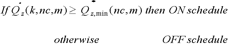
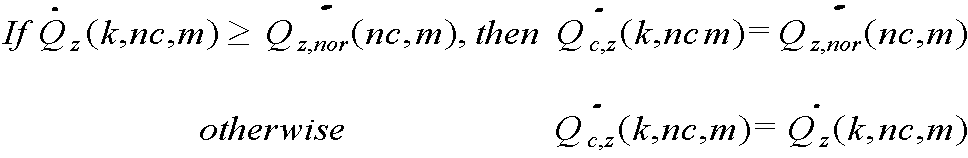
- equation (8) and equation (9) For each zone The required heat quantity of the demand side system and the operation schedule of the device are determined, and the operation schedule is determined by the automatic control device, where the devices installed for each zone of the demand side system, that is, AHU, FCU and other devices (EHP), respectively.
- the amount of heating / heating energy (or ratio) that is in charge of the supply is set in advance and inputted to the MMI, and the supply-side system supplies cooling / heating energy according to the amount of cooling / heating energy for each device of the demand-side system set by the automatic controller in advance. do.
- Time Forecast heating and cooling loads of demand-side devices by zone and time in Is the minimum allowable heat capacity of the demand side system equipment that supplies heating and cooling energy to the zone, Silver air conditioning And heating Index value that distinguishes.
- Time Any demand-side system appliance in Required calories Is the demand side system appliance ( Is the nominal calorific value of Silver air conditioning And heating Index value to distinguish between.
- the objective function and equation of Equation 10 below are considered in consideration of the operating performance and capacity of the supply-side system device which varies according to the operating conditions and the external air condition based on the cooling and heating load of the whole building calculated by the above process.
- the supply calories and the operation schedule of the apparatus constituting the supply side system are determined so that all of the constraints of Equations 11 and 12 are satisfied, and the operation schedule is determined by the automatic control apparatus by the operation of the stored control program.
- Silver time Is the sum of the required calories of the demand-side system receiving cold or hot water from the supply-side system.
- Supply-side system appliances ( ) Is the amount of heat to be supplied when cooling or heating, Supply-side system appliances ( ) Is the nominal capacity of Supply-side system appliances ( ) Is the minimum dose.
- Performance And equipment according to the air condition ( ) 'S performance ( ) are used as initial values, and the standard values given in the operating manual of the device are used. Is periodically updated based on the actual operating data of the The actual operation data of) is input to the automatic control device in real time through the communication network, and the device (according to the operation condition) ) 'S performance ( ) And equipment according to the air condition ( ) 'S performance ( ) Is updated periodically.
- the warm-up time is required to operate each device constituting the supply-side system and the demand-side system, and the operation of these devices must consider the preheating / preheating time of the building and the remaining cooling / heating time of the system.
- the operation schedule of each device constituting the supply side system and the demand side system is set to be adjusted in consideration of the preheating / preheating time of the building, the residual cooling / residual heat time of the system, and the warming up time of the device through the control program stored in the control device.
- the operation schedule of each device constituting the demand-side system and the supply-side system is determined by the above process, the operation schedule is input to and stored in the automatic control device that controls the entire air conditioning system.
- the operation of each device constituting the demand-side system and the supply-side system is controlled through a communication network according to the input and stored operation schedule, whereby the air conditioning system is optimally operated unattended without the help of a driver.
- the power consumption is predicted in advance in a specific time zone, for example, during a peak time in summer, by Equation 13 below, wherein the estimated power consumption is expected to be higher than the set allowable power.
- the operation of the demand-side system is blocked by setting the operation of the device constituting the demand-side system according to a preset operation scenario, by sequentially shutting down the power of the device constituting the demand-side system from the low-priority device according to a preset operation scenario.
- the operating load of the supply-side system equipment is reduced by the amount of heat, and if the estimated power consumption is lowered below the allowable power in a specific time period, the power supply of the demand-side system equipment is reversed from the power-off order in order from the most important devices.
- the type and setting of the operation scenario is through the program stored in the automatic control unit.
- Is a random time Represents the total electrical energy usage of the supply-side system in Is a random time
- On the supply side system appliance ( ) Is the amount of calories Is the electrical energy consumption of each device used to supply the required calories, Indicates the performance of the device according to the operating conditions, Indicates the performance of the device according to the outside air condition, Silver air conditioning And heating Index value to distinguish between.
- the ice storage system is often included in the supply-side system, and such ice storage system is mainly operated so that ice storage occurs during the late night power time when the electric energy charge is low, even when the outside temperature is low. Compared to the case where the outside air temperature is high, more electrical energy should be input. Therefore, in the present invention, when the operation schedule of the ice storage system is determined, the ice storage operation is performed during the late night power time. The operation is performed at the time before and after the estimated time.
- the present invention predicts the air-conditioning and heating load of the building in advance, and operates the air conditioning system in consideration of the performance of the device that varies according to the energy bill and the heat source according to the time and season based on the estimated heating and cooling load.
- the most economical operation is possible, and since this operation is automatically performed by a control program stored in the automatic controller, an effective unmanned operation is achieved without an experienced driver.
Landscapes
- Engineering & Computer Science (AREA)
- Chemical & Material Sciences (AREA)
- Combustion & Propulsion (AREA)
- Mechanical Engineering (AREA)
- General Engineering & Computer Science (AREA)
- Air Conditioning Control Device (AREA)
Abstract
Description
본 발명은 공기조화시스템의 최적제어 방법에 관한 것으로, 더욱 상세하게는 건물의 시간별 냉난방부하를 사전에 예측하고, 이 예측된 냉난방부하를 바탕으로 시간별, 계절별로 다른 에너지 요금과 열원별로 달라지는 기기의 성능 등을 고려하여 공기조화시스템을 숙련된 운전자 없이도 가장 효율적이며 경제적으로 무인 운전할 수 있도록 하는 공기조화시스템의 무인 최적제어 방법에 관한 것이다.The present invention relates to a method for optimal control of an air conditioning system, and more particularly, to predict an air-conditioning and heating load of a building in advance, and based on the predicted air-heating load, a device that varies by energy rate and heat source according to time and season. Considering the performance and the like, the present invention relates to an unmanned optimal control method of an air conditioning system that enables an unmanned operation of an air conditioning system without the need for an experienced operator most efficiently and economically.
우리나라 전체 에너지 수요 중 많은 부분이 공기조화시스템의 운전에 사용되고 있기 때문에 에너지 절감을 달성하기 위해서는 공기조화시스템에 대한 경제적이며 효율적인 운전방법의 개발이 필요한데, 공기조화시스템의 효율적 운전을 달성하기 위해서는 먼저 건물의 냉난방부하에 대한 정확한 예측이 선행되어야 하고, 이 예측된 냉난방부하에 맞추어 공기조화시스템을 구성하는 여러 종류의 기기를 적절히 조합하여 운전하여야 한다.Since much of Korea's total energy demand is used for the operation of the air conditioning system, in order to achieve energy saving, it is necessary to develop an economical and efficient operation method for the air conditioning system. Precise predictions of heating and cooling loads should be made first, and the various types of equipment constituting the air conditioning system should be operated in accordance with the predicted heating and cooling loads.
운전자가 냉난방부하에 맞추어 공기조화시스템 기기를 조합하여 운전할 때에는 운전 매뉴얼이나 운전자 자신의 지식 또는 경험을 토대로 운전하는데, 운전 매뉴얼에 운전 과정에서 발생될 수 있는 모든 상황을 기술하는 데에 한계가 있기 때문에 결국 운전자의 판단에 맡겨야 하며, 이때 운전자의 판단이 잘못되거나 또는 운전 미숙으로 인해 불필요한 전력이 소모되거나 냉난방부하를 충족하지 못하여 실내 거주자의 불편을 초래하는 경우가 발생하기도 한다.When the driver operates the air conditioning system in combination with the heating and cooling load, he / she operates based on the driver's manual or the driver's own knowledge or experience, because the driver's manual has limitations in describing all situations that may occur during the driving process. As a result, it is left to the driver's judgment, and sometimes the driver's judgment is wrong or unsatisfactory driving consumes unnecessary power or fails to meet the heating and cooling load, which may cause inconvenience to indoor residents.
한편, 우리나라의 경우 현재 공기조화시스템의 에너지원으로서 전기와 도시가스가 주로 사용되고 있으며, 특히 전기는 시간대별, 사용량에 따라 그 요금이 다르고, 특히 여름철 피크 시간동안의 전력 요금이 가장 비쌀 뿐만 아니라 피크 시간 중에 전력을 일정량 이상 사용하게 되면 피크시간의 요금을 기준으로 전력요금의 기본료가 산출되기 때문에 자칫 과다한 전력 요금이 청구될 수 있다.On the other hand, in Korea, electricity and city gas are mainly used as energy sources of air-conditioning system. Especially, electricity is different depending on the time of day and usage. In particular, electricity charge is the most expensive during peak time in summer. If a certain amount of power is used during the time, the base rate of the power rate is calculated on the basis of the peak time rate, and excessive power charges may be charged.
따라서 운전자의 판단에 근거한 운전방식에서 벗어나 좀 더 과학적이고 합리적인 공기조화시스템의 운전 전략과 운전 소요비용을 줄일 수 있는 전략의 수립이 요구되는데, 이에 본 출원인은 '냉방시스템의 최적 운전방법'을 제안하여 등록(특허 제0949044호)을 받은바 있으며, 이 방법은 건물의 시간별 냉방부하를 사전에 예측하고, 이 예측된 냉방부하에 기초하여 시간별, 계절별로 다른 전기 및 가스 요금과 열원별로 달라지는 냉방기기의 성능을 고려하여 냉방시스템을 운전하며, 이에 의해 냉방부하에 적절히 대응하면서도 가장 저비용으로 냉방시스템을 운전할 수 있도록 한 것이다.Therefore, it is required to establish a strategy that can reduce the operation cost and operation cost of a more scientific and reasonable air conditioning system, away from the driving method based on the driver's judgment. Therefore, the applicant proposes an 'optimal operation method of the cooling system'. Has been registered (Patent No. 0949044), and this method predicts the cooling load per hour of the building in advance, and based on the estimated cooling load, the cooling device that varies with electricity and gas rates and heat sources according to time and season. The cooling system is operated in consideration of the performance of the cooling system, and thus the cooling system can be operated at the lowest cost while appropriately responding to the cooling load.
공기조화시스템은 일반적으로 도 1에 도시된 바와 같이 각 존별로 설치되어 각 존별 냉난방 에너지 수요에 맞추어 냉난방 에너지를 공급함으로써 직접 실내를 냉난방하는 AHU(Air Handling Unit), FCU(Fan Coil Unit) 등으로 이루어진 복수 조의 수요측 시스템과, 이 복수 조의 수요측 시스템에서 필요로 하는 전체 냉난방 에너지를 충당하여 공급하는 냉동기, 보일러 등으로 이루어진 공급측 시스템으로 나눌 수 있는데, 위의 특허 제0949044호에서는 공급측 시스템의 최적제어방법만 제시하고 있을 뿐 수요측 시스템의 제어방법은 제시하고 있지 않다.As shown in FIG. 1, an air conditioning system is generally installed in each zone and supplies air-conditioning energy according to air-conditioning energy demand of each zone, thereby directly cooling and heating the room to an AHU (Fan Coil Unit) and the like. It can be divided into a supply side system consisting of a plurality of sets of demand-side systems and a refrigerator, a boiler, etc. to supply and supply the total cooling and heating energy required by the plurality of sets of demand-side systems. It only shows the control method, not the control method of the demand side system.
그러나 공기조화시스템 전체에 대한 효율적이고 최적의 운전을 달성하기 위해서는 공급측 시스템뿐만 아니라 수요측 시스템에 대한 제어도 동시에 이루어져야 하는데, 상기 특허에서와 같이 공급측 시스템만 제어하는 경우 건물 전체에 대한 냉난방부하를 예측하는 것만으로도 충분하지만, 공급측 시스템과 더불어 수요측 시스템도 제어하는 경우에는 수요측 시스템은 건물의 존별로 분리 설치되기 때문에 수요측 시스템을 제어하기 위해서는 존별 냉난방부하에 대한 예측도 이루어져야 하며, 또한 수요측 시스템의 요구열량과 존별 수요측 시스템을 각각 구성하는 기기의 운전특성도 고려하여야 한다.However, in order to achieve efficient and optimal operation of the entire air conditioning system, the control of not only the supply side system but also the demand side system must be performed simultaneously. When only the supply side system is controlled as in the above patent, the heating and cooling load of the entire building is predicted. It is enough to do this, but in case of controlling the demand side system as well as the supply side system, since the demand side system is installed in each zone of the building, it is necessary to make predictions about the heating and cooling load for each zone to control the demand side system. Consideration should also be given to the heat requirements of the side systems and the operating characteristics of the equipment constituting the zones on the demand side by zone.
더구나 흡수식 냉온수기, 히트펌프와 같이 냉방과 난방에 모두 사용되는 기기는 동절기 및 하절기에서와 같이 외기상태가 다른 경우 그 성능이 완전히 달라지기 때문에 위 특허 제0949044호의 냉방시스템 제어방법을 난방시스템에 적용하기 위해서는 외기상태에 따른 기기의 성능변화도 고려하여야 한다.Moreover, the equipment used for both cooling and heating, such as absorption chiller and heat pump, heat pump, the performance is completely different when the air condition is different, like in winter and summer, so the cooling system control method of Patent No. 0949044 applies to the heating system. For this purpose, changes in the performance of the equipment due to external conditions should also be considered.
한편, 위에서 설명한 바와 같이 피크 시간 중에 일정량 이상의 전력을 사용하는 경우 이 피크시간 동안의 요금을 기준으로 전력요금이 산출되기 때문에 운전자는 자신의 판단에 따라 공급측 시스템 및/또는 수요측 시스템을 구성하는 기기의 일부 전원을 강제 차단함으로써 피크 시간 중의 전력 사용량을 줄이는데, 이와 같이 운전자의 판단에 의거하는 경우 필요 이상의 많은 기기의 전원을 차단함으로써 실내 거주자의 불편을 초래할 수 있을 뿐만 아니라, 반드시 냉방이 이루어져야 하는 존의 기기의 전원도 자칫 차단하게 됨으로써 해당 존에 설치된 기기의 오작동을 유발할 우려가 있으며, 따라서 피크 시간 중의 전력 사용량이 일정량 이상으로 예상되는 경우 운전자의 자의적인 판단에 의존하지 않고 미리 합리적으로 계획된 운전절차(시나리오)에 따라 기기의 운전을 자동적으로 제어할 수 있는 제어방법의 개발이 요구된다.On the other hand, as described above, when a certain amount of power is used during the peak time, the power rate is calculated based on the rate during the peak time, so that the driver configures the supply side system and / or the demand side system at his / her own discretion. By forcibly shutting off some of the power, the power consumption is reduced during peak hours.In the case of the driver's judgment, it is possible to cut off the power of many devices more than necessary, which may cause inconvenience to the indoor residents, and the zone which must be cooled It may also cause the malfunction of the equipment installed in the zone by shutting off the power of the equipment. Therefore, if the power consumption during the peak time is expected to be higher than a certain amount, the reasonably planned operation procedure in advance without depending on the driver's arbitrary judgment (In scenario) Accordingly, the development of a control method that can automatically control the operation of the device is required.
본 발명은 상기와 같은 종래의 공기조화시스템의 제어방법이 가지는 문제점을 개선하기 위해 안출된 것으로, 본 발명은 각 존별 냉난방부하에 기초한 건물 전체 냉난방 부하를 사전에 예측하고, 이 예측된 냉난방부하를 바탕으로 공기조화시스템을 숙련된 운전자 없이도 효율적이며 경제적으로 무인 운전할 수 있도록 하는 공기조화시스템의 무인 최적제어 방법을 제공하는 데에 그 목적이 있다.The present invention has been made to improve the problems of the conventional control method of the air conditioning system as described above, the present invention is predicted in advance the overall heating and cooling load of the building based on the heating and cooling load for each zone, and the estimated heating and cooling load The purpose is to provide an unmanned optimal control method of the air conditioning system that enables the air conditioning system to operate unattended efficiently and economically without an experienced operator.
상기와 같은 본 발명의 목적은 공기조화시스템의 무인 최적제어 방법을, 자동제어장치에서 외기상태와 건물의 각 존별 냉난방부하를 각각 사전에 예측한 다음, 상기 예측된 각 존별 냉난방부하에 기초하여 수학식 8과 수학식 9를 만족하도록 각 존별 수요측 시스템 기기의 요구열량과 운전 스케줄을 결정하고, 자동제어장치에서 상기 각 존별 냉난방부하 또는 요구열량을 합산하여 건물 전체의 냉난방부하와 공급열량을 예측하며, 상기 예측된 건물 전체의 냉난방부하를 기반으로 시간별, 계절별로 다른 에너지 요금, 운전조건 및 외기상태에 따라 달라지는 공급측 기기의 성능과 용량을 고려하여 수학식 10의 목적함수와 수학식 11 및 수학식 12의 구속조건이 모두 만족되도록 공급측 시스템의 공급열량과 운전 스케줄을 결정하고, 결정된 수요측 시스템과 공급측 시스템의 운전 스케줄은 각각 운전자의 도움 없이 자동제어장치에 저장된 제어 프로그램에 의해 자동으로 설정되어 운전되도록 구성하는 것에 의해 달성된다.The object of the present invention as described above is to predict the air conditioning and the heating and cooling loads of each zone of the building in advance in the unmanned optimum control method of the air conditioning system, and then based on the estimated heating and cooling loads for each zone To satisfy Equation 8 and Equation 9 For each zone Determine the required heat and operation schedule of the demand-side system equipment, and estimate the heating and cooling load and the heat supply of the entire building by adding the heating and cooling load or the required heat for each zone in the automatic control device, and calculates the estimated heating and cooling load of the whole building Supply-side system to satisfy both the objective function of Equation 10 and the constraints of Equation 11 and Equation 12 in consideration of the performance and capacity of the supply-side device, which vary according to the energy rate, operation conditions, and outdoor conditions, which vary according to time and season. By determining the supply calories and the operation schedule of the supply-side system, and the determined operation schedule of the demand-side system and the supply-side system are respectively set and operated automatically by a control program stored in the automatic control unit without the help of the driver.
[수학식 8][Equation 8]
[수학식 9][Equation 9]

[수학식 10][Equation 10]
![]()
![]()
[수학식 11][Equation 11]
![]()
![]()
[수학식 12][Equation 12]
![]()
![]()
그리고 본 발명은 결정된 공급측 시스템과 수요측 시스템의 운전 스케줄에 따라 공급측 기기와 수요측 기기를 운전할 때 자동제어장치에 저장된 제어 프로그램에 의해 수학식 13에 따라 특정 시간대에서의 기의 전력 사용량을 미리 예측하고, 예측된 전력 사용량이 설정된 허용전력 이상인 경우에는 운전 스케줄에 따라 운전하지 않고 미리 설정된 시나리오에 따라 수요측 시스템 기기의 전원을 자동으로 차단시킴으로써 차단된 수요측 시스템의 요구열량만큼 상기 공급측 시스템의 공급열량을 줄여가면서 운전되도록 하고, 특정 시간대에서의 예측 전력 사용량이 허용전력 이하로 다시 내려간 경우에는 수요측 시스템 기기의 전원을 전원 차단순서와 역순으로 자동으로 공급하도록 하는 것을 특징으로 한다.According to the present invention, when operating the supply side device and the demand side device according to the determined operation schedule of the supply side system and the demand side system, the power consumption of the machine in a certain time period is predicted in advance by the control program stored in the automatic control device according to Equation (13). When the estimated power consumption is more than the set allowable power, the supply side system is supplied by the required heat quantity of the demand side system which is cut off by automatically shutting off the power of the demand side system device according to the preset scenario without operating according to the operation schedule. It operates while reducing the heat, and when the estimated power consumption is lowered below the allowable power at a certain time, it is characterized by automatically supplying the power of the demanding system equipment in the reverse order of the power off sequence.
[수학식 13][Equation 13]
![]()
![]()
또한 본 발명은 공급측 시스템과 수요측 시스템의 운전 스케줄은 각각 자동제어장치에서 건물의 예냉/예열 시간, 시스템의 잔냉/잔열시간, 기기의 워밍업 시간을 고려하여 조정되는 것을 또 다른 특징으로 한다.In another aspect, the present invention is characterized in that the operation schedule of the supply side system and the demand side system is adjusted in consideration of the pre-cooling / pre-heating time of the building, the remaining cooling / residual heat time of the system, the warm-up time of the equipment in the automatic control device.
이에 더해 본 발명은 운전조건에 따른 기기의 성능과 외기상태에 따른 기기의 성능이 각각 운전매뉴얼에서 제시하는 표준값을 초기값으로 사용하고, 기기의 실제 운전 데이터에 기초하여 자동제어장치에 저장된 제어 프로그램에 의해 수시로 업데이트되는 것을 또 다른 특징으로 한다.In addition, according to the present invention, the performance of the device according to the operating conditions and the performance of the device according to the external conditions are respectively used as initial values, and the control program stored in the automatic control device based on the actual operation data of the device. It is another feature that is updated from time to time.
그리고 본 발명은 건물의 각 존별 냉난방부하 중 일사부하와 전열부하가 각각 전열특성계수와 일사특성계수로 표현되는 건물부하특성계수를 적용하여 자동제어장치에 저장된 프로그램에 의해 수학식 6 및 수학식 7을 통해 구하는 것을 또 다른 특징으로 한다.In the present invention, the solar load and the heat transfer load of the heating and cooling loads of each zone of the building are applied to the building load characteristic coefficients represented by the heat transfer characteristic coefficient and the solar radiation coefficient, respectively. Finding through is another feature.
[수학식 6][Equation 6]
![]()
![]()
[수학식 7][Equation 7]
![]()
![]()
또한 본 발명은 건물의 각 존별 냉난방부하를 예측할 때 전열특성계수와 일사특성계수를 모르는 경우에는 전열특성계수와 일사특성계수의 대푯값을 각각 자동제어장치에 저장된 프로그램에 입력한 다음, 실제부하를 바탕으로 자동제어장치에 저장된 프로그램의 동작에 의해 대푯값을 조정함으로써 냉난방부하를 예측하는 것을 또 다른 특징으로 한다.In addition, the present invention, when predicting the heating and cooling load for each zone of the building, if the heat transfer coefficient and the solar radiation coefficient is not known, the representative values of the heat transfer coefficient and solar radiation coefficient, respectively, into the program stored in the automatic control device, and then based on the actual load Another feature is to predict the heating and cooling load by adjusting the representative value by the operation of the program stored in the automatic control device.
이에 더하여 본 발명은, 공기조화시스템의 운전상태는 수요측 시스템 기기의 운전상태가 상기 자동제어장치에 실시간으로 피드백됨으로써 이에 기초하여 실제의 냉난방부하가 계산되고, 냉난방부하의 예측에 사용되는 건물부하특성계수는 과거의 실제 냉난방부하를 바탕으로 주기적으로 조정되는 것을 또 다른 특징으로 한다.In addition, according to the present invention, the operating condition of the air conditioning system is fed back to the automatic control device in real time, and the actual heating and cooling load is calculated based on this, and the building load used for the prediction of the heating and cooling load. Another characteristic is that the characteristic coefficient is periodically adjusted based on past actual heating and cooling loads.
그리고 본 발명은, 예측된 냉난방부하가 자동제어장치에 저장된 제어 프로그램의 동작에 의해 조정된 건물부하특성계수를 적용함으로써 다시 산출되고, 수요측 시스템과 공급측 시스템의 운전 스케줄은 각각 다시 산출된 냉난방부하를 기반으로 자동제어장치에 저장된 제어 프로그램에 의해 자동으로 수정되는 것을 또 다른 특징으로 한다.In the present invention, the predicted heating and cooling load is calculated again by applying the building load characteristic coefficient adjusted by the operation of the control program stored in the automatic control device, and the operating schedules of the demand-side system and the supply-side system are respectively calculated again. Another feature is that it is automatically modified by the control program stored in the automatic control device based on.
또한 본 발명은 냉난방부하의 예측에 사용되는 건물부하특성계수가 유전자 알고리즘에 의해 조정되는 것을 또 다른 특징으로 한다.In another aspect, the present invention is characterized in that the building load characteristic coefficient used for the prediction of heating and cooling load is adjusted by a genetic algorithm.
이에 더하여 본 발명은 공급측 시스템에 빙축열 시스템이 포함되고, 빙축열 시스템의 운전 스케줄은 자동제어장치에 저장된 제어 프로그램에 의해 심야전력 시간 중 외기온도가 가장 낮은 것으로 예측된 시간을 기준으로 전후로 설정되는 것을 또 다른 특징으로 한다.In addition, the present invention includes the ice heat storage system in the supply-side system, the operation schedule of the ice heat storage system is set back and forth on the basis of the time predicted to be the lowest outside temperature of the midnight power time by the control program stored in the automatic control device. It is another feature.
본 발명은 냉난방시스템의 조합방식과 운전 스케줄 등을 운전자의 경험과 노하우에 의존하지 않고 무인으로 최적 운전됨으로써 주어진 냉난방부하 조건을 만족시키면서 냉난방시스템의 운전비용을 최소화하고, 쾌적한 냉난방을 하면서도 냉난방에너지와 전력피크를 줄일 수 있으며 아울러 기기의 효율적 운용을 달성할 수 있다.The present invention minimizes the operating cost of the heating and cooling system while satisfying the given cooling and heating load conditions by operating unattended optimally without depending on the driver's experience and know-how, such as the combination method and operation schedule of the cooling and heating system, while providing a comfortable heating and cooling energy Power peaks can be reduced and efficient operation of the device can be achieved.
그리고 본 발명은 공조대상 건물의 창호와 벽체에서의 전열부하와 일사부하 특성을 구분하고 방위별 일사특성 등을 반영함으로써 종래에 비해 더욱 정확하게 냉난방부하를 산출할 수 있다.In addition, the present invention can calculate the heating and cooling load more accurately than the conventional by distinguishing the heat transfer and solar load characteristics of the windows and walls of the air conditioning target building and reflecting the solar radiation characteristics for each direction.
또한 본 발명은 공급측 시스템뿐만 아니라 수요측 시스템에 대한 냉난방 부하를 예측한 다음, 이에 기초하여 공급측 시스템과 수요측 시스템을 동시에 제어하며, 이와 더불어 수요측 시스템의 요구열량과 존별 수요측 시스템을 각각 구성하는 기기의 운전특성 및 외기상태에 따른 기기의 성능변화도 고려하여 공기조화시스템을 운전하기 때문에 더욱 쾌적하고 경제적인 공기조화시스템의 운전이 달성될 수 있다.In addition, the present invention predicts the heating and cooling loads on the demand side system as well as the supply side system, and simultaneously controls the supply side system and the demand side system on the basis of this, and also configures the required calories of the demand side system and the demand side system for each zone. Since the air conditioning system is operated in consideration of the operating characteristics of the equipment and the performance change of the equipment according to the external air condition, a more comfortable and economical operation of the air conditioning system can be achieved.
이에 추가하여 본 발명은 피크 시간대에서의 전력 사용량을 미리 예측하고, 예측된 전력 사용량이 설정된 허용전력 이상으로 예상되는 경우 운전자의 판단에 의존하지 않고 미리 계획된 운전 시나리오에 따라 운전되도록 함으로써 실내 거주자의 불편과 기기의 오작동 등을 최소로 할 수 있다.In addition, the present invention predicts the power consumption in peak time in advance, and if the estimated power consumption is expected to be above the set allowable power, the inconvenience of the indoor residents by driving according to the planned driving scenario without depending on the driver's judgment And malfunction of the equipment can be minimized.
이에 더하여 본 발명은 빙축열 시스템의 운전 스케줄을 결정할 때 외기온도가 가장 낮은 것으로 예측된 심야전력 시간 중에 운전이 이루어지도록 함으로써 빙축열 시스템 운전에 투입되는 에너지 비용을 최소로 할 수 있다.In addition, the present invention can minimize the energy cost for operating the ice storage system by determining that the operation is performed during the late night power time when the outside temperature is predicted to be the lowest when determining the operation schedule of the ice storage system.
더욱이 본 발명은 창호와 벽체의 전열특성계수와 일사특성계수에 각각 전열조정계수와 일사조정계수를 도입하여 이들을 각각 유전자 알고리즘을 사용하여 조정함으로써 예측부하와 실측부하 사이의 불일치를 대폭 줄일 수 있다.Furthermore, the present invention introduces heat transfer adjustment coefficients and solar radiation adjustment coefficients into the heat transfer coefficients and the solar radiation coefficients of windows and walls, respectively, and adjusts them using genetic algorithms, thereby significantly reducing the inconsistency between the predicted load and the measured load.
도 1은 공급측 시스템과 수요측 시스템으로 이루어진 공기조화시스템의 예를 나타낸 구성도이다.1 is a configuration diagram showing an example of an air conditioning system composed of a supply side system and a demand side system.
이하에서는 바람직한 실시예를 도시한 첨부 도면을 통해 본 발명의 구성과 작용을 더욱 상세히 설명한다.Hereinafter, the configuration and operation of the present invention through the accompanying drawings showing a preferred embodiment in more detail.
본 발명은 숙련된 운전자 없이도 공기조화시스템을 효과적이며 경제적으로 무인 운전할 수 있도록 하는 공기조화시스템의 무인 최적제어 방법을 제공하고자 하는 것으로, 이러한 목적을 달성하기 위해서는 공기조화시스템을 운전하기 전에 먼저 건물의 냉난방부하에 대한 예측이 선행되어야 하고, 이 예측된 냉난방부하를 기준으로 공기조화시스템에 구비된 자동제어장치의 제어에 의해 공기조화시스템을 운전하여야 한다.The present invention is to provide an unmanned optimal control method of the air conditioning system to enable an unmanned operation of the air conditioning system effectively and economically without an experienced driver. Prediction of heating and cooling load should be preceded, and the air conditioning system should be operated by the control of the automatic control unit provided in the air conditioning system based on the predicted heating and cooling load.
본 발명의 자동제어장치를 포함하여 공기조화시스템을 제어하기 위한 자동제어장치는 일반적으로 통합제어실에 설치되어 내부에 제어 프로그램(소프트웨어)을 구비함으로써 공기조화시스템을 통합 제어하는 MMI(Man Machine Interface)와, 각 관제점과 연결된 DDC(Direct Digital Controller)와, MMI와 DDC 간의 데이터 교환을 담당하는 NC(Network Controller), DDC의 확장을 위한 모듈 등을 포함하며, 이하에서는 이러한 구성을 포함하는 자동제어장치를 이용하여 공기조화시스템을 무인 최적 제어하는 방법에 대해 설명한다.The automatic control device for controlling the air conditioning system including the automatic control device of the present invention is generally installed in an integrated control room and has a control program (software) therein to provide integrated control of the air conditioning system. And a direct digital controller (DDC) connected to each control point, an NC (network controller) that is responsible for data exchange between the MMI and the DDC, a module for expanding the DDC, and the like. A method of unmanned optimal control of an air conditioning system using a device will be described.
일반적으로, 공기조화시스템은 위에서 설명한 바와 같이 각 존별로 설치되어 각 존별 냉난방 에너지 수요에 맞추어 냉난방 에너지를 공급함으로써 직접 실내를 냉난방하는 AHU(Air Handling Unit), FCU(Fan Coil Unit) 등으로 이루어진 복수 개의 수요측 시스템과, 이 복수 개의 수요측 시스템에서 실내로 공급하는 전체 냉난방 에너지를 충당할 수 있도록 냉난방 에너지를 공급하는 냉동기, 보일러 등으로 이루어진 공급측 시스템으로 나눌 수 있다.In general, the air conditioning system is installed in each zone as described above, and is provided with a plurality of air handling units (AHUs) and fan coil units (FCUs) for directly heating and cooling the room by supplying heating and cooling energy according to the cooling and heating energy demand for each zone. It can be divided into a supply-side system composed of two demand-side systems and a refrigerator, a boiler, and the like for supplying heating and cooling energy to cover the entire cooling and heating energy supplied from the plurality of demand-side systems to the room.
본 발명에서 냉난방 부하를 예측할 때에는 먼저 자동제어장치에서 건물의 각 존별 냉난방 부하, 즉 복수 개의 수요측 시스템을 각각 구성하는 기기가 공급하여야 하는 냉난방 에너지(냉난방 부하)를 예측하여 산출한 다음, 이 각 존별로 산출된 냉난방 부하를 합산하여 공급측 시스템이 공급하여야 하는 전체 냉난방 부하를 산출하며, 이때 자동제어장치에는 복수 개의 수요측 시스템을 각각 구성하는 기기가 공급하여야 하는 냉난방 부하를 예측 산출하고, 공급측 시스템이 공급하여야 하는 전체 냉난방 부하를 산출할 수 있도록 냉난방 부하 등을 산출하기 위한 제어 프로그램(소프트웨어)이 저장된다.In the present invention, when the heating and cooling load is predicted, the automatic control device first calculates and calculates the heating and cooling load for each zone of the building, that is, the heating and cooling energy (cooling and heating load) to be supplied by the devices constituting the plurality of demand side systems. The total heating and cooling loads to be supplied by the supply side system are calculated by summing the heating and cooling loads calculated for each zone.In this case, the automatic control device predicts and calculates the heating and cooling loads to be supplied by the devices constituting a plurality of demand side systems. The control program (software) for calculating the heating / cooling load or the like is stored so that the total heating / cooling load to be supplied is calculated.
그리고 각 존별 냉난방 부하를 사전에 예측하여 산출할 때에는 각 존을 구성하는 실내의 냉난방 부하 특성, 즉 실(room)의 방향에 따라 일사량 등이 달라지고, 실내에 거주하는 사람의 수 등에 따라 환기량 등이 달라지기 때문에 이러한 특성으로 고려하여 냉난방 부하를 산출하여야 하며, 따라서 본 발명에서는 본 출원인이 제안한 특허 제1506215호의 냉난방부하 예측방법에 의해 냉난방 부하를 산출하되, 각 존별로 나누어 산출하며, 이하에서는 위 특허에서 제시하고 있는 냉난방 부하 산출방법을 간단히 설명한다.When calculating and calculating the heating / cooling load for each zone in advance, the amount of solar radiation varies depending on the characteristics of the heating / cooling load of the room constituting each zone, that is, the direction of the room, and the amount of ventilation according to the number of people living in the room. Since the cooling and heating load should be calculated in consideration of these characteristics, the present invention calculates the heating and cooling load by the heating and cooling load prediction method of Patent No. 1506215 proposed by the applicant, but is calculated by dividing each zone, below The cooling and heating load calculation method proposed in the patent will be briefly described.
건물의 각 존별 냉난방 부하를 예측하여 산출할 때 외기의 상태가 냉난방 부하에 절대적인 영향을 미치기 때문에 외기상태에 대한 예측이 선행되어야 하는데, 외기상태에 대한 예측은 본 출원인이 특허 제1141027호를 통해 제안한 시간별 기상데이터 예측방법을 비롯하여 많은 예측방법이 이미 알려져 있으므로 이러한 공지의 외기상태 예측방법 중 어느 한 가지 방법을 선택하여 외기상태를 예측한다.When predicting and calculating the heating and cooling loads of each zone of a building, the condition of the outside air has an absolute influence on the heating and cooling load, so the prediction of the outside air condition must be preceded. The prediction of the outside air condition is proposed by the applicant through Patent No. 1141027. Since many prediction methods are already known, including the hourly weather data prediction method, any one of these known outdoor condition prediction methods is selected to predict the outdoor condition.
상기와 같은 외기상태 예측방법에 의해 외기상태가 예측되고 나면 다시 각 존별 냉난방 부하를 산출한다.After the outdoor air condition is predicted by the external air condition predicting method as described above, the cooling / heating load for each zone is calculated again.
냉난방부하는 일반적으로 아래의 수학식 1에서와 같이 일사부하(![]()
![]()
![]()
![]()
![]()
![]()
![]()
![]()
![]()
![]()
![]()
![]()
![]()
![]()
![]()
![]()
![]()
![]()
![]()
![]()
[수학식 1][Equation 1]
![]()
![]()
여기서, ![]()
![]()
![]()
![]()
![]()
![]()
![]()
![]()
![]()
![]()
![]()
![]()
![]()
![]()
[수학식 2][Equation 2]
![]()
![]()
여기서, ![]()
![]()
![]()
![]()
![]()
![]()
![]()
![]()
![]()
![]()
![]()
![]()
![]()
![]()
![]()
![]()
[수학식 3][Equation 3]
![]()
![]()
여기서, ![]()
![]()
![]()
![]()
![]()
![]()
그리고 건물부하특성계수는 종래에서와 같이 부하계산서로부터 구할 수 없기 때문에 본 발명에서는 에너지평형법에 근거한 건물에너지 시뮬레이션 프로그램, 예를 들면 EnergyPlus를 사용하여 창호의 전열특성계수(![]()
![]()
![]()
![]()
![]()
![]()
![]()
![]()
[수학식 4][Equation 4]
![]()
![]()
여기서, ![]()
![]()
![]()
![]()
![]()
![]()
![]()
![]()
![]()
![]()
[수학식 5][Equation 5]
![]()
![]()
여기서, ![]()
![]()
![]()
![]()
![]()
![]()
창호의 일사특성계수(![]()
![]()
![]()
![]()
![]()
![]()
![]()
![]()
![]()
![]()
![]()
![]()
![]()
![]()
[수학식 6][Equation 6]
![]()
![]()
여기서, 상수 ![]()
![]()
![]()
![]()
![]()
![]()
![]()
![]()
[수학식 7][Equation 7]
![]()
![]()
여기서, ![]()
![]()
![]()
![]()
![]()
![]()
![]()
![]()
![]()
![]()
![]()
![]()
![]()
![]()
본 발명은 상기와 같이 건물부하특성계수를 이용하여 각 존별 냉반방 부하를 예측할 수 있는데, 건물의 설계자료의 유실 등으로 인해 건물부하특성계수, 즉 전열특성계수와 일사특성계수를 구할 수 없는 경우도 있을 수 있으며, 이 경우에는 자동제어장치에 저장된 제어 프로그램에 건물부하특성계수의 대표값을 입력한 다음, 실제부하를 바탕으로 건물부하특성계수를 조정하면 각 존별 냉난방부하를 예측할 수 있는데, 이를 위해 수요측 시스템 기기의 운전상태가 자동제어장치에 실시간으로 피드백되고, 이에 기초하여 실제의 냉난방부하가 자동제어장치에서 계산된다.The present invention can predict the cold half load of each zone by using the building load characteristic coefficient as described above, but the building load characteristic coefficient, that is, the heat transfer coefficient and the solar radiation coefficient cannot be obtained due to the loss of design data of the building. In this case, by inputting the representative value of the building load characteristic coefficient into the control program stored in the automatic control device, and then adjusting the building load characteristic coefficient based on the actual load, it is possible to predict the heating and cooling load for each zone. The operational status of the demand side system equipment is fed back to the automatic control device in real time, and based on this, the actual cooling and heating load is calculated by the automatic control device.
그리고 냉난방부하를 예측할 때 사용된 건물부하특성계수는 자동제어장치에에 저장된 제어 프로그램의 동작에 의해 실제의 냉난방부하를 바탕으로 주기적으로 조정된다.And the building load characteristic coefficients used in estimating the heating and cooling load are periodically adjusted based on the actual heating and cooling load by the operation of the control program stored in the automatic control device.
상기와 같은 과정에 의해 예측된 존별 냉난방부하는 실제의 부하(실측부하)와 차이가 있을 수 있으며, 따라서 본 발명에서는 창호와 벽체의 전열특성계수(![]()
![]()
![]()
![]()
![]()
![]()
![]()
![]()
![]()
![]()
![]()
![]()
![]()
![]()
![]()
![]()
![]()
![]()
![]()
![]()
![]()
![]()
![]()
![]()
그리고 유전자 알고리즘을 사용하여 변수(일사조정계수(![]()
![]()
![]()
![]()
상기와 같은 과정에 의해 자동제어장치에서의 각 존별 예측 냉방부하가 산출되고 나면, 이 산출된 각 존별 예측 냉난방부하에 기초하여 각 존별로 설치된 수요측 시스템을 구성하는 기기에 대한 운전계획이 수립되어야 하는데, 본 발명에서는 아래의 수학식 8과 수학식 9를 만족하도록 각 존별 수요측 시스템의 요구열량과 기기의 운전 스케줄을 결정하며, 이러한 운전 스케줄의 결정은 자동제어장치에서 이루어지고, 이때 수요측 시스템의 존별로 설치된 기기, 즉 AHU, FCU 및 기타 기기(EHP)가 각각 담당하여 공급하는 냉난방 에너지 양(또는 비율)은 사전에 설정되어 MMI에 입력되며, 공급측 시스템에서는 자동제어장치에 의해 사전에 설정된 수요측 시스템의 기기별 냉난방 에너지 양(비율)에 따라 냉난방 에너지를 공급한다.After the prediction cooling load for each zone in the automatic control apparatus is calculated by the above process, an operation plan for the equipment constituting the demand side system installed in each zone must be established based on the calculated prediction cooling load for each zone. In the present invention, to satisfy the following equation (8) and equation (9) For each zone The required heat quantity of the demand side system and the operation schedule of the device are determined, and the operation schedule is determined by the automatic control device, where the devices installed for each zone of the demand side system, that is, AHU, FCU and other devices (EHP), respectively. The amount of heating / heating energy (or ratio) that is in charge of the supply is set in advance and inputted to the MMI, and the supply-side system supplies cooling / heating energy according to the amount of cooling / heating energy for each device of the demand-side system set by the automatic controller in advance. do.
[수학식 8][Equation 8]

여기서, ![]()
![]()
![]()
![]()
![]()
![]()
![]()
![]()
![]()
![]()
![]()
![]()
[수학식 9][Equation 9]
여기서, ![]()
![]()
![]()
![]()
![]()
![]()
![]()
![]()
![]()
![]()
![]()
![]()
![]()
![]()
![]()
![]()
다음, 위와 같은 과정에 의해 각 존별 냉난방부하 또는 요구열량이 산출되고 나면, 이들 냉난방부하 또는 요구열량을 모두 합산하여 공급측 시스템에서 공급하여야 하는 건물 전체의 냉난방부하와 공급열량을 계산하며, 이러한 계산과정은 자동제어장치에서 이루어진다.Next, after the heating and cooling loads or the required calories for each zone are calculated by the above process, all the heating and cooling loads or the required calories are summed up to calculate the heating and cooling loads and the calorific values of the entire building to be supplied by the supply system. Is done at the automatic control unit.
한편, 위에서 설명한 바와 같이 전기에너지 요금이 시간별, 계절별로 다르고, 또한 외기상태에 따라 공급측 시스템의 기기 성능이 달라지기 때문에 공기조화시스템의 경제적인 운전과 효율적인 운전을 달성하기 위해서는 이러한 점을 고려하여야 한다.On the other hand, as described above, since electric energy charges vary by hour and season, and the equipment performance of the supply side system varies according to the outside air condition, this point should be considered in order to achieve economical operation and efficient operation of the air conditioning system. .
이에 따라 본 발명에서는 상기와 같은 과정에 의해 산출된 건물 전체의 냉난방부하를 기반으로 운전조건 및 외기상태에 따라 달라지는 공급측 시스템 기기의 운전성능과 용량을 고려하여 아래 수학식 10의 목적함수와 수학식 11 및 수학식 12의 구속조건이 모두 만족되도록 공급측 시스템을 구성하는 기기의 공급열량과 운전 스케줄을 결정하며, 이러한 운전 스케줄의 결정은 저장된 제어 프로그램의 동작에 의해 자동제어장치에서 이루어진다.Accordingly, in the present invention, the objective function and equation of Equation 10 below are considered in consideration of the operating performance and capacity of the supply-side system device which varies according to the operating conditions and the external air condition based on the cooling and heating load of the whole building calculated by the above process. The supply calories and the operation schedule of the apparatus constituting the supply side system are determined so that all of the constraints of Equations 11 and 12 are satisfied, and the operation schedule is determined by the automatic control apparatus by the operation of the stored control program.
[수학식 10][Equation 10]
![]()
![]()
여기서, ![]()
![]()
![]()
![]()
![]()
![]()
![]()
![]()
![]()
![]()
![]()
![]()
![]()
![]()
![]()
![]()
![]()
![]()
![]()
![]()
![]()
![]()
[수학식 11][Equation 11]
![]()
![]()
여기서 ![]()
![]()
![]()
![]()
[수학식 12][Equation 12]
![]()
![]()
여기서 ![]()
![]()
![]()
![]()
![]()
![]()
![]()
![]()
![]()
![]()
![]()
![]()
위의 수학식 10에서 운전조건에 따른 기기(![]()
![]()
![]()
![]()
![]()
![]()
![]()
![]()
![]()
![]()
![]()
![]()
![]()
![]()
![]()
![]()
![]()
![]()
![]()
![]()
그리고 공급측 시스템과 수요측 시스템을 구성하는 각 기기를 운전할 때 워밍업 시간이 요구될 뿐만 아니라 이들 기기의 운전은 건물의 예냉/예열 시간과 시스템의 잔냉/잔열시간을 고려하여야 하며, 따라서 본 발명에서는 자동제어장치에 저장된 제어 프로그램을 통해 공급측 시스템과 수요측 시스템을 구성하는 각 기기의 운전 스케줄은 각각 건물의 예냉/예열 시간, 시스템의 잔냉/잔열시간, 기기의 워밍업 시간을 고려하여 조정되도록 설정된다.In addition, the warm-up time is required to operate each device constituting the supply-side system and the demand-side system, and the operation of these devices must consider the preheating / preheating time of the building and the remaining cooling / heating time of the system. The operation schedule of each device constituting the supply side system and the demand side system is set to be adjusted in consideration of the preheating / preheating time of the building, the residual cooling / residual heat time of the system, and the warming up time of the device through the control program stored in the control device.
상기와 같은 과정에 의해 수요측 시스템과 공급측 시스템을 구성하는 각 기기의 운전 스케줄이 결정되고 나면, 이 운전 스케줄은 전체 공기조화시스템을 제어하는 자동제어장치에 입력되어 저장되며, 따라서 자동제어장치는 이 입력되어 저장된 운전 스케줄에 따라 수요측 시스템과 공급측 시스템을 구성하는 각 기기의 운전을 통신망을 통해 제어하고, 이에 의해 공기조화시스템은 운전자의 도움 없이도 최적으로 무인 운전된다.After the operation schedule of each device constituting the demand-side system and the supply-side system is determined by the above process, the operation schedule is input to and stored in the automatic control device that controls the entire air conditioning system. The operation of each device constituting the demand-side system and the supply-side system is controlled through a communication network according to the input and stored operation schedule, whereby the air conditioning system is optimally operated unattended without the help of a driver.
그리고 결정된 운전 스케줄에 따라 공급측 시스템 기기를 운전할 때에는 아래의 수학식 13에 의해 특정 시간대, 예를 들면 여름철 피크 시간대에서의 전력 사용량을 미리 예측하고, 이때 예측된 전력 사용량이 설정된 허용전력 이상으로 예상되는 경우에는 기기의 운전을 운전 스케줄에 따라 운전하지 않고 미리 설정된 운전 시나리오에 따라 수요측 시스템을 구성하는 기기의 전원을 중요도가 낮은 기기부터 순차적으로 차단시켜 가면서 운전하도록 설정함으로써 차단된 수요측 시스템의 요구열량만큼 공급측 시스템 기기의 운전부하가 경감되도록 하고, 만약 특정 시간대에서의 예측 전력 사용량이 허용전력 이하로 다시 내려간 경우에는 수요측 시스템 기기의 전원을 전원 차단순서와 역순으로, 중요도가 높은 기기부터 순차적으로 전원 공급을 자동으로 재개하도록 설정되며, 이러한 운전 시나리오의 입력과 설정은 자동제어장치에 저장된 프로그램을 통해 이루어진다.When operating the supply side system device according to the determined operation schedule, the power consumption is predicted in advance in a specific time zone, for example, during a peak time in summer, by
[수학식 13][Equation 13]
![]()
![]()
여기서, ![]()
![]()
![]()
![]()
![]()
![]()
![]()
![]()
![]()
![]()
![]()
![]()
![]()
![]()
![]()
![]()
![]()
![]()
![]()
![]()
![]()
![]()
한편, 건물의 냉방 에너지를 절약하기 위해 공급측 시스템에 빙축열 시스템이 포함되는 경우가 많고, 이러한 빙축열 시스템은 주로 전기에너지 요금이 낮은 심야전력 시간 중에 빙축이 이루어지도록 운전되는데, 이때에도 외기온도가 낮은 경우에 비해 외기온도가 높은 경우에 상대적으로 더 많은 전기에너지가 투입되어야 하며, 따라서 본 발명에서는 빙축열 시스템의 운전 스케줄을 결정할 때 심야전력 시간 중에 빙축 운전이 이루어지도록 하되, 이 경우에도 외기온도가 가장 낮은 것으로 예측된 시간을 기준으로 전후 시간에 운전이 이루어지도록 한다.On the other hand, in order to save the building's cooling energy, the ice storage system is often included in the supply-side system, and such ice storage system is mainly operated so that ice storage occurs during the late night power time when the electric energy charge is low, even when the outside temperature is low. Compared to the case where the outside air temperature is high, more electrical energy should be input. Therefore, in the present invention, when the operation schedule of the ice storage system is determined, the ice storage operation is performed during the late night power time. The operation is performed at the time before and after the estimated time.
이상 설명한 바와 같이 본 발명은 건물의 시간별 냉난방부하를 사전에 예측하고, 이 예측된 냉난방부하를 바탕으로 시간별, 계절별로 다른 에너지 요금과 열원별로 달라지는 기기의 성능을 고려하여 공기조화시스템을 운전하기 때문에 가장 경제적으로 운전할 수 있으며, 또한 이러한 운전이 자동제어장치에 저장된 제어 프로그램에 의해 자동적으로 이루어지기 때문에 숙련된 운전자 없이도 효과적인 무인 운전이 달성된다.As described above, the present invention predicts the air-conditioning and heating load of the building in advance, and operates the air conditioning system in consideration of the performance of the device that varies according to the energy bill and the heat source according to the time and season based on the estimated heating and cooling load. The most economical operation is possible, and since this operation is automatically performed by a control program stored in the automatic controller, an effective unmanned operation is achieved without an experienced driver.
Claims (10)


Applications Claiming Priority (2)
| Application Number | Priority Date | Filing Date | Title |
|---|---|---|---|
| KR1020150133426A KR101571806B1 (en) | 2015-09-21 | 2015-09-21 | Self-operating Optimal Control Method for Air Conditioning System |
| KR10-2015-0133426 | 2015-09-21 |
Publications (1)
| Publication Number | Publication Date |
|---|---|
| WO2017052079A1 true WO2017052079A1 (en) | 2017-03-30 |
Family
ID=54845791
Family Applications (1)
| Application Number | Title | Priority Date | Filing Date |
|---|---|---|---|
| PCT/KR2016/009211 Ceased WO2017052079A1 (en) | 2015-09-21 | 2016-08-19 | Unmanned optimal control method for air conditioning system |
Country Status (2)
| Country | Link |
|---|---|
| KR (1) | KR101571806B1 (en) |
| WO (1) | WO2017052079A1 (en) |
Cited By (1)
| Publication number | Priority date | Publication date | Assignee | Title |
|---|---|---|---|---|
| US11168916B2 (en) | 2018-06-11 | 2021-11-09 | Broan-Nutone Llc | Ventilation system with automatic flow balancing derived from a neural network and methods of use |
Families Citing this family (4)
| Publication number | Priority date | Publication date | Assignee | Title |
|---|---|---|---|---|
| KR102379638B1 (en) * | 2017-09-27 | 2022-03-29 | 삼성전자주식회사 | Control device for air conditioning and control method therefor |
| KR102032810B1 (en) * | 2018-11-19 | 2019-10-17 | 뉴브로드테크놀러지(주) | Hvac system interlocking based air conditioner automatic control apparatus |
| CN113837665B (en) * | 2021-11-04 | 2024-04-19 | 华北电力大学 | Regional electric heating load prediction method based on intelligent body modeling |
| CN115978720B (en) * | 2022-12-30 | 2023-07-04 | 北京创今智能科技有限公司 | Unequal grouping method for air source heat pump units |
Citations (5)
| Publication number | Priority date | Publication date | Assignee | Title |
|---|---|---|---|---|
| JP2000146257A (en) * | 1998-09-04 | 2000-05-26 | Atr Adaptive Communications Res Lab | Control method and apparatus for building energy system and recording medium storing control processing program |
| JP2003120982A (en) * | 2001-10-16 | 2003-04-23 | Hitachi Ltd | Air conditioning equipment operation system and air conditioning equipment design support system |
| JP2008025951A (en) * | 2006-07-25 | 2008-02-07 | Jfe Techno Research Corp | Operation control method and apparatus for air conditioning equipment |
| KR100949044B1 (en) * | 2009-08-07 | 2010-03-24 | 충남대학교산학협력단 | Optimized operation method for cooling system |
| KR101506215B1 (en) * | 2015-01-16 | 2015-03-26 | (주)가교테크 | Prediction Method of Cooling and Heating Loads Using Predicted Solar Insolation |
-
2015
- 2015-09-21 KR KR1020150133426A patent/KR101571806B1/en active Active
-
2016
- 2016-08-19 WO PCT/KR2016/009211 patent/WO2017052079A1/en not_active Ceased
Patent Citations (5)
| Publication number | Priority date | Publication date | Assignee | Title |
|---|---|---|---|---|
| JP2000146257A (en) * | 1998-09-04 | 2000-05-26 | Atr Adaptive Communications Res Lab | Control method and apparatus for building energy system and recording medium storing control processing program |
| JP2003120982A (en) * | 2001-10-16 | 2003-04-23 | Hitachi Ltd | Air conditioning equipment operation system and air conditioning equipment design support system |
| JP2008025951A (en) * | 2006-07-25 | 2008-02-07 | Jfe Techno Research Corp | Operation control method and apparatus for air conditioning equipment |
| KR100949044B1 (en) * | 2009-08-07 | 2010-03-24 | 충남대학교산학협력단 | Optimized operation method for cooling system |
| KR101506215B1 (en) * | 2015-01-16 | 2015-03-26 | (주)가교테크 | Prediction Method of Cooling and Heating Loads Using Predicted Solar Insolation |
Cited By (1)
| Publication number | Priority date | Publication date | Assignee | Title |
|---|---|---|---|---|
| US11168916B2 (en) | 2018-06-11 | 2021-11-09 | Broan-Nutone Llc | Ventilation system with automatic flow balancing derived from a neural network and methods of use |
Also Published As
| Publication number | Publication date |
|---|---|
| KR101571806B1 (en) | 2015-11-25 |
Similar Documents
| Publication | Publication Date | Title |
|---|---|---|
| WO2017052079A1 (en) | Unmanned optimal control method for air conditioning system | |
| WO2016114477A1 (en) | Method of estimating indoor heating and cooling loads by using estimated insolation | |
| CN113251602B (en) | Method, device and smart air conditioner for controlling air conditioner | |
| EP3134860A1 (en) | Operating method and apparatus of smart system for power consumption optimization | |
| CN105143781A (en) | Air-conditioning control system and method | |
| EP2980496A1 (en) | Air conditioning control device, air conditioning control system, and air conditioning control method | |
| CA2123727A1 (en) | Temperature Control System Having Central Control for Thermostats | |
| WO2016108420A1 (en) | Solar radiation prediction method | |
| WO2017159982A1 (en) | Microgrid operation system and method | |
| JP3318846B2 (en) | Flexible equipment control device | |
| WO2019017555A1 (en) | System and method for optimizing building energy on basis of indoor environment parameter prediction and dynamic user setup | |
| WO2021141188A1 (en) | Energy-saving dynamic production scheduling operation method for parallel thermal treatment processing | |
| EP3278033A1 (en) | Apparatus and method for adaptively applying central hvac system and individual hvac system | |
| CN118347072B (en) | Self-adaptive refrigeration control method and device based on ice cold accumulation system | |
| WO2019093575A1 (en) | Waste heat recovery heating system of building | |
| US20230175705A1 (en) | Heating device | |
| CN118151689A (en) | A control system and method for adjusting the temperature of temperature control equipment in a computer room | |
| WO2023018226A1 (en) | Power management device and method using predicted power peak guideline | |
| WO2020111336A1 (en) | Method for tracking maximum power point of photovoltaic power conversion apparatus | |
| EP4350234B1 (en) | A heating and/or cooling system for collective residential housing units, a control device therefor and a method for the control thereof | |
| EP4350238A1 (en) | A heating and/or cooling system for collective residential housing units, a control device therefor and a method for the control thereof | |
| van Leeuwen et al. | Central model predictive control of a group of domestic heat pumps case study for a small district | |
| CN107883525A (en) | A kind of central air-conditioning intelligence energy-saving operation control system and method | |
| US20070199336A1 (en) | System and method of controlling environmental conditioning equipment in an enclosure | |
| JP2020070945A (en) | Air conditioning system and air condition control method |
Legal Events
| Date | Code | Title | Description |
|---|---|---|---|
| 121 | Ep: the epo has been informed by wipo that ep was designated in this application |
Ref document number: 16848805 Country of ref document: EP Kind code of ref document: A1 |
|
| NENP | Non-entry into the national phase |
Ref country code: DE |
|
| 122 | Ep: pct application non-entry in european phase |
Ref document number: 16848805 Country of ref document: EP Kind code of ref document: A1 |