WO2016075803A1 - Dispositif et procédé de mise en forme - Google Patents
Dispositif et procédé de mise en forme Download PDFInfo
- Publication number
- WO2016075803A1 WO2016075803A1 PCT/JP2014/080152 JP2014080152W WO2016075803A1 WO 2016075803 A1 WO2016075803 A1 WO 2016075803A1 JP 2014080152 W JP2014080152 W JP 2014080152W WO 2016075803 A1 WO2016075803 A1 WO 2016075803A1
- Authority
- WO
- WIPO (PCT)
- Prior art keywords
- modeling
- optical system
- condensing optical
- target surface
- incident
- Prior art date
- Legal status (The legal status is an assumption and is not a legal conclusion. Google has not performed a legal analysis and makes no representation as to the accuracy of the status listed.)
- Ceased
Links
Images

Classifications
-
- B—PERFORMING OPERATIONS; TRANSPORTING
- B22—CASTING; POWDER METALLURGY
- B22F—WORKING METALLIC POWDER; MANUFACTURE OF ARTICLES FROM METALLIC POWDER; MAKING METALLIC POWDER; APPARATUS OR DEVICES SPECIALLY ADAPTED FOR METALLIC POWDER
- B22F3/00—Manufacture of workpieces or articles from metallic powder characterised by the manner of compacting or sintering; Apparatus specially adapted therefor ; Presses and furnaces
- B22F3/10—Sintering only
- B22F3/105—Sintering only by using electric current other than for infrared radiant energy, laser radiation or plasma ; by ultrasonic bonding
Definitions
- the present invention relates to a modeling apparatus and a modeling method, and more particularly to a modeling apparatus and a modeling method for forming a three-dimensional modeled object on a target surface.
- the modeling apparatus and the modeling method according to the present invention can be suitably used for forming a three-dimensional modeled object by rapid prototyping (sometimes referred to as 3D printing, addition manufacturing, or direct digital manufacturing).
- a technique for directly generating 3D (three-dimensional) shapes from CAD data is called rapid prototyping (sometimes called 3D printing, additive manufacturing, or direct digital manufacturing, but hereinafter rapid prototyping is used as a generic term). This has contributed to the production of prototypes mainly for the purpose of shape confirmation with extremely short lead times. If a modeling apparatus that forms a three-dimensional modeled object by rapid prototyping, such as a 3D printer, is classified according to the material to be handled, it can be broadly classified into one that handles resin and one that handles metal. A metal three-dimensional structure manufactured by rapid prototyping is used as an actual part exclusively, unlike the case of resin.
- M3DP Metal 3D Printer
- PBF Powder Bed Two types are well known: Fusion
- DED Directed Energy Deposition
- a sintered metal powder is thinly layered on a bed on which a workpiece is mounted, and a high-energy laser beam is scanned with a galvanometer mirror or the like to melt and solidify the portion hit by the beam.
- the bed is lowered by the thickness of one layer, and the sintered metal powder is spread again there, and the same is repeated. In this manner, modeling is repeated layer by layer to obtain a desired three-dimensional shape.
- PBF Planar Biharmonic Deformation
- DED a method in which a dissolved metal material is adhered to a processing target.
- powder metal is injected in the vicinity of the focal point of the laser beam focused by the condenser lens. Then, the powder metal is melted by laser irradiation and becomes liquid. If there is an object to be processed near the focal point, the liquefied metal adheres to the object to be processed, and is cooled and solidified again. This focal portion becomes a so-called pen tip, and it is possible to draw “thick lines” one after another on the surface to be processed.
- a desired shape is formed by appropriately moving one of a processing target and a processing head (laser, powder injection nozzle, etc.) relative to the other based on CAD data (see, for example, Patent Document 1).
- DED has been improved compared to PBF in handling of powder metal as a raw material, but there are many points to be improved.
- a modeling apparatus for forming a three-dimensional modeled object on a target surface, the beam irradiation including a moving system that moves the target surface and a condensing optical system that emits a beam.
- a beam processing system including: a material processing unit having at least one supply port for supplying a modeling material irradiated with a beam from the beam irradiation unit, the target surface, and a beam from the beam irradiation unit.
- a control device for controlling the moving system and the beam shaping system from the at least one supply port to an optical axis on the exit surface side of the condensing optical system or an axis parallel to the optical axis.
- the build material Te is supplied, is emitted from the exit surface of the light converging optical system, the beam passing through the optical path inclined relative to the optical axis, the shaped device to be irradiated to the building material is provided.
- the target surface is a surface on which a target site for modeling is set.
- a modeling apparatus for forming a three-dimensional modeled object on a target surface, and includes a moving system that moves the target surface and a beam irradiation system that emits a beam. And a material processing unit having at least one supply port for supplying a modeling material, and supplying from the material processing unit while relatively moving the target surface and the beam from the beam irradiation unit Based on 3D data of a three-dimensional structure to be formed on the target surface so that the target material on the target surface is shaped by irradiating the beam to the modeling material to be formed, A control device for controlling the beam shaping system, wherein the modeling material is supplied along the vertical direction from the at least one supply port, and is emitted from an exit surface of the condensing optical system. The beam passing through the optical path inclined relative to the optical axis of the outgoing side of the optical system, modeling apparatus to be irradiated on the building material is provided.
- a modeling method for forming a three-dimensional modeled object on the target surface wherein the beam emitted from the beam irradiation unit including the condensing optical system and the target surface are relatively moved.
- the beam from the beam irradiation unit Including performing modeling on a target portion on the target surface by controlling at least one of an injection state and a supply state of the modeling material, and performing the modeling includes an emission surface side of the condensing optical system
- the modeling material is supplied along an optical axis of the optical axis or an axis parallel to the optical axis, the beam is emitted from the exit surface of the condensing optical system, and passes through an optical path inclined with respect to the optical axis.
- a modeling method for forming a three-dimensional structure on a target surface wherein the beam emitted from the beam irradiation unit including the condensing optical system and the target surface are moved relative to each other.
- the beam from the beam irradiation unit Including shaping a target portion on the target surface by controlling at least one of an injection state and a supply state of the modeling material, and in performing the modeling, the modeling material is along a vertical direction.
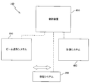
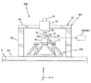
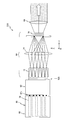
- FIG. 1 It is a block diagram which shows the whole structure of the modeling apparatus which concerns on one Embodiment. It is a figure which shows the structure of a movement system schematically with a measurement system. It is a perspective view which shows the movement system with which the workpiece
- FIG. 9A is an enlarged view of the inside of circle A in FIG. 4, and FIG. 9B is a view showing the relationship between one character area shown in FIG. 9A and the scan direction. It is a figure which shows an example of the irradiation area
- FIG. 12B are diagrams for explaining one effect of the modeling apparatus according to the embodiment in comparison with the prior art. It is a figure for demonstrating the example which performs the additional process with respect to a workpiece
- FIG. 15A and FIG. 15B are diagrams for explaining an example in which the thickness of the coating layer is increased by slightly increasing the width of one character region.
- FIG. 1 is a block diagram showing the overall configuration of a modeling apparatus 100 according to an embodiment.
- the modeling apparatus 100 is a DED M3DP.
- the modeling apparatus 100 can also be used to form a three-dimensional modeled object on the table 12 described later by rapid prototyping, but performs additional processing by three-dimensional modeling on a workpiece (for example, an existing part). It can also be used to do. In the present embodiment, the description will be made centering on the case of performing additional machining on the latter workpiece. In actual manufacturing, it is common to repeat the processing of parts produced with different manufacturing methods, different materials, or different machine tools, and tailor them to the desired parts. The requirements for processing are potentially the same.
- the modeling apparatus 100 includes a moving system 200, a measurement system 400, a beam modeling system 500, and a control apparatus 600 that includes these systems and controls the entire modeling apparatus 100.
- the measurement system 400 and the beam shaping system 500 are arranged separately in a predetermined direction. In the following description, for convenience, it is assumed that the measurement system 400 and the beam shaping system 500 are arranged apart from each other in the X-axis direction (see FIG. 2) described later.
- FIG. 2 schematically shows the configuration of the mobile system 200 together with the measurement system 400.
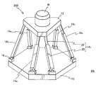
- FIG. 3 is a perspective view of the moving system 200 on which the workpiece W is mounted.
- the horizontal direction in FIG. 2 is defined as the Y-axis direction
- the direction orthogonal to the paper surface is defined as the X-axis direction
- the direction orthogonal to the X-axis and Y-axis is defined as the Z-axis direction.
- the rotation (tilt) direction will be described as ⁇ x, ⁇ y, and ⁇ z directions, respectively.
- the moving system 200 changes the position and orientation of a modeling target surface (here, a surface on which the target portion TA on the workpiece W is set) TAS (see, for example, FIGS. 4 and 9A). Specifically, by driving a workpiece having a target surface and a table (described later) on which the workpiece is mounted in directions of six degrees of freedom (X-axis, Y-axis, Z-axis, ⁇ x, ⁇ y, and ⁇ z directions), Change the position of the target surface in the direction of 6 degrees of freedom.
- a modeling target surface here, a surface on which the target portion TA on the workpiece W is set
- TAS see, for example, FIGS. 4 and 9A.
- the positions of the three degrees of freedom in the ⁇ x, ⁇ y, and ⁇ z directions of the table, work, or target surface are collectively referred to as “posture” as appropriate, and the remaining three degrees of freedom directions (X The positions of the axis, the Y-axis, and the Z-axis direction) are collectively referred to as “position” where appropriate.
- the moving system 200 includes a Stewart platform type 6-degree-of-freedom parallel link mechanism as an example of a drive mechanism that changes the position and posture of the table.
- the moving system 200 is not limited to one that can drive the table in the direction of 6 degrees of freedom.
- the moving system 200 (excluding the stator of a planar motor described later) is disposed on a base BS installed on the floor F so that its upper surface is substantially parallel to the XY plane.
- the moving system 200 includes a regular hexagonal slider 10 constituting a base platform, a table 12 constituting an end effector, and six expansion / contractions connecting the slider 10 and the table 12.
- Possible rods (links) 14 1 to 14 6 and expansion / contraction mechanisms 16 1 to 16 6 (not shown in FIG. 3, but refer to FIG. 11) provided on the rods 14 1 to 14 6 to expand and contract the rods.
- Possible rods (links) 14 1 to 14 6 and expansion / contraction mechanisms 16 1 to 16 6 (not shown in FIG. 3, but refer to FIG. 11) provided on the rods 14 1 to 14 6 to expand and contract the rods.
- the moving system 200 has a structure in which the movement of the table 12 can be controlled with six degrees of freedom in a three-dimensional space by independently adjusting the lengths of the rods 14 1 to 14 6 with the extension mechanisms 16 1 to 16 6. ing. Since the moving system 200 includes a Stewart platform type 6-degree-of-freedom parallel link mechanism as a driving mechanism of the table 12, it has features such as high accuracy, high rigidity, large support force, and easy inverse kinematics calculation. .
- a beam to be described later is more specifically described with respect to the beam modeling system 500 in order to form a modeled object having a desired shape on the workpiece at the time of additional processing on the workpiece.
- the position and posture of the work (table 12) are controlled with respect to the beam from the irradiation unit.
- the beam from the beam irradiation unit may be movable, or both the beam and the work (table) may be movable.
- the beam shaping system 500 since the beam shaping system 500 has a complicated configuration, it is easier to move the workpiece.
- the table 12 is made of a plate member having a shape that is obtained by cutting off each vertex of the equilateral triangle.
- a workpiece W to be subjected to additional processing is mounted on the upper surface of the table 12.
- the table 12 is provided with a chuck mechanism 13 (not shown in FIG. 3, refer to FIG. 11) for fixing the workpiece W.
- a mechanical chuck or a vacuum chuck is used as the chuck mechanism 13.
- the table 12 is not limited to the shape shown in FIG. 3, and may have any shape such as a rectangular plate shape or a disk shape.
- each end of each of the rods 14 1 to 14 6 is connected to the slider 10 and the table 12 via the universal joint 18. Further, the rods 14 1 and 14 2 are connected in the vicinity of one vertex position of the triangle of the table 12, and the slider 10 and the rods 14 1 and 14 2 constitute an approximate triangle. Yes. Similarly, the rods 14 3 and 14 4 and the rods 14 5 and 14 6 are respectively connected in the vicinity of the remaining vertex positions of the triangle of the table 12, and the slider 10, the rods 14 3 , 14 4 , and the rod 14 are connected. 5 and 14 6 are arranged so as to form an approximate triangle.
- Each of these rods 14 1 to 14 6 includes a first shaft member 20 and a second shaft member 22 that are relatively movable in the respective axial directions, as representatively shown for rod 14 1 in FIG.
- One end (lower end) of the first shaft member 20 is attached to the slider 10 via the universal joint 18, and the other end (upper end) of the second shaft member 22 has a universal joint on the table 12. Is attached through.
- a stepped cylindrical hollow portion is formed inside the first shaft member 20, and a bellows type air cylinder, for example, is accommodated at the lower end side of the hollow portion.
- a pneumatic circuit and an air pressure source are connected to the air cylinder. Then, by controlling the air pressure of the compressed air supplied from the air pressure source via the pneumatic circuit, the internal pressure of the air cylinder is controlled so that the piston of the air cylinder is reciprocated in the axial direction. It has become.
- the return process uses gravity that acts on the piston when it is incorporated into the parallel link mechanism.
- an armature unit (not shown) composed of a plurality of armature coils arranged in the axial direction is disposed on the upper end side in the hollow portion of the first shaft member 20.
- the second shaft member 22 has one end (lower end) inserted into the hollow portion of the first shaft member 20.
- One end of the second shaft member 22 is formed with a small-diameter portion having a smaller diameter than the other portions, and a circular-shaped mover yoke made of a magnetic member is provided around the small-diameter portion. It has been.
- On the outer peripheral portion of the mover yoke a hollow columnar shape composed of a plurality of permanent magnets having the same dimensions, that is, a cylindrical magnet body is provided.
- a hollow cylindrical magnet unit is constituted by the mover yoke and the magnet body.
- the armature unit and the magnet unit constitute a shaft motor that is a kind of electromagnetic force linear motor.
- a sinusoidal drive current having a predetermined period and a predetermined amplitude is supplied to each coil of the armature unit, which is a stator, so that a gap between the magnet unit and the armature unit is obtained.
- the second shaft member 22 is driven relative to the first shaft member 20 in the axial direction by Lorentz force (driving force) generated by electromagnetic interaction, which is a kind of electromagnetic interaction.
- the first shaft member 20 and the second shaft member 22 are relatively driven in the axial direction by the air cylinder and the shaft motor described above to expand and contract each of the rods 14 1 to 14 6 .
- the aforementioned telescopic mechanisms 16 1 to 16 6 are respectively configured.
- the magnet unit that is the mover of the shaft motor is supported in a non-contact manner with respect to the armature unit that is the stator via an air pad provided on the inner peripheral surface of the first shaft member 20.
- each of the rods 14 1 to 14 6 has an absolute linear that detects the axial position of the second shaft member 22 with respect to the first shaft member 20.
- Encoders 24 1 to 24 6 are provided, and outputs of these linear encoders 24 1 to 24 6 are supplied to the control device 600 (see FIG. 11).
- the axial position of the second shaft member 22 detected by the linear encoders 24 1 to 24 6 corresponds to the length of each of the rods 14 1 to 14 6 .
- the telescopic mechanisms 16 1 to 16 6 are controlled by the control device 600 (see FIG. 11). Details of the configuration of the parallel link mechanism similar to the mobile system 200 of the present embodiment are disclosed in, for example, US Pat. No. 6,940,582, and the control device 600 is disclosed in the above US patent specification.
- the position and posture of the table 12 are controlled via the expansion and contraction mechanisms 16 1 to 16 6 by using the inverse kinematics calculation in the same manner as described above.
- the telescopic mechanisms 16 1 to 16 63 provided on the rods 14 1 to 14 6 respectively include an air cylinder arranged in series (or in parallel) and a shaft motor that is a kind of electromagnetic force linear motor. Therefore, in the control device 600, the table 12 can be driven roughly coarsely and finely and finely moved by the shaft motor by air pressure control of the air cylinder. As a result, the position of the table 12 in the 6-degree-of-freedom direction (that is, the position and orientation) can be accurately controlled in a short time.
- each of the rods 14 1 to 14 6 has an air pad that supports the magnet unit, which is the mover of the shaft motor, in a non-contact manner with respect to the armature unit, which is the stator. Friction, which is a non-linear component when controlling expansion and contraction, can be avoided, whereby the position and posture of the table 12 can be controlled with higher accuracy.
- a shaft motor is used as the electromagnetic force linear motor constituting the expansion / contraction mechanisms 94 1 to 94 6 , and the shaft motor uses a magnet unit in which a cylindrical magnet is used on the mover side. Therefore, magnetic flux (magnetic field) is generated in all directions in the radial direction of the magnet, and the magnetic flux in all directions can be contributed to the generation of Lorentz force (driving force) due to electromagnetic interaction. Compared to a motor or the like, a clearly large thrust can be generated, and the size can be easily reduced as compared to a hydraulic cylinder or the like.
- each rod includes a shaft motor, it is possible to simultaneously realize a reduction in size and weight and an improvement in output, which can be suitably applied to the modeling apparatus 100.
- control device 600 can suppress low-frequency vibrations by controlling the air pressures of the air cylinders that constitute the expansion and contraction mechanisms, and can insulate high-frequency vibrations by controlling the current to the shaft motor.
- the moving system 200 further includes a planar motor 26 (see FIG. 11).
- a mover of a planar motor 26 made of a magnet unit (or coil unit) is provided on the bottom surface of the slider 10.
- a flat surface made of a coil unit (or magnet unit) is formed inside the base BS.
- the stator of the motor 26 is accommodated.
- a plurality of air bearings are provided on the bottom surface of the slider 10 so as to surround the mover, and the slider 10 is finished with high flatness (guide surface) by the plurality of air bearings. It is levitated and supported above via a predetermined clearance (gap or gap).
- the slider 10 is driven in the XY plane in a non-contact manner with respect to the upper surface of the base BS by electromagnetic force (Lorentz force) generated by electromagnetic interaction between the stator and the movable element of the planar motor 26.
- the moving system 200 is arranged between the arrangement positions of the measurement system 400, the beam shaping system 500, and the work transfer system 300 (not shown in FIG. 1, see FIG. 11).
- the table 12 can be moved freely.
- the moving system 200 may include a plurality of tables 12 on which the workpieces W are mounted. For example, while processing using the beam shaping system 500 is performed on a workpiece held on one of a plurality of tables, measurement using the measurement system 400 is performed on a workpiece held on another table.
- each table may be freely movable between the arrangement positions of the measurement system 400, the beam shaping system 500, and the workpiece transfer system 300 (not shown in FIG. 1, refer to FIG. 11).
- a table that holds the workpiece exclusively during measurement using the measurement system 400 and a table that holds the workpiece exclusively during machining using the beam shaping system 500 are provided, and the workpiece is loaded into the two tables.
- each slider 10 may be fixed on the base BS. Even when a plurality of tables 12 are provided, each table 12 is movable in the direction of 6 degrees of freedom, and the position in the direction of 6 degrees of freedom can be controlled.
- the planar motor 26 is not limited to the air levitation method, and a magnetic levitation method planar motor may be used. In the latter case, the slider 10 need not be provided with an air bearing. As the planar motor 26, either a moving magnet type or a moving coil type can be used.
- the control device 600 controls the slider 10 in the X and Y two-dimensional directions on the base BS by controlling at least one of the magnitude and direction of the current supplied to each coil of the coil unit constituting the planar motor 26. Can be driven.
- the moving system 200 includes a position measurement system 28 (see FIG. 11) that measures position information regarding the X-axis direction and the Y-axis direction of the slider 10.
- a position measurement system 28 (see FIG. 11) that measures position information regarding the X-axis direction and the Y-axis direction of the slider 10.
- a two-dimensional absolute encoder can be used as the position measurement system 28 . Specifically, a two-dimensional scale having a belt-like absolute cord with a predetermined width over the entire length in the X-axis direction is provided on the upper surface of the base BS, and a light source such as a light emitting element is provided on the bottom surface of the slider 10 correspondingly.
- a configured X head and Y head are provided.
- As a two-dimensional scale for example, on a non-reflective substrate (reflectance 0%), a plurality of square reflecting portions (with a constant period) along two directions (X-axis direction and Y-axis direction) orthogonal to each other ( Marks) are two-dimensionally arranged, and the reflection characteristic (reflectance) of the reflection portion has a gradation according to a predetermined rule.
- the two-dimensional absolute encoder for example, the same configuration as the two-dimensional absolute encoder disclosed in US Patent Application Publication No. 2014/0070073 may be adopted. According to the absolute two-dimensional encoder having the same configuration as that of US Patent Application Publication No. 2014/0070073, it is possible to measure two-dimensional position information with high accuracy equivalent to that of a conventional incremental encoder. Since it is an absolute encoder, unlike the incremental encoder, origin detection is not required. Measurement information of the position measurement system 28 is sent to the control device 600.
- position information in this embodiment, shape information
- a target surface for example, the upper surface
- additional processing modeling
- the target value of the target surface TAS on the workpiece W is controlled by open loop control of the position of the table 12 in the direction of 6 degrees of freedom based on the measurement results of the linear encoders 24 1 to 24 6 and the position measurement system 28.
- Position control in the direction of 6 degrees of freedom with respect to is possible.
- absolute encoders are used as the linear encoders 24 1 to 24 6 and the position measuring system 28, so that it is not necessary to return to the origin, so that resetting is easy.
- the above-described position information in the three-dimensional space is not limited to the shape, and it is sufficient if the position information is at least three points according to the shape of the target surface.
- a linear motor may be used instead of the planar motor 26.
- a position measurement system for measuring the position information of the slider 10 may be configured by an absolute linear encoder.
- the position measurement system for measuring the position information of the slider 10 is not limited to the encoder, and may be configured using an interferometer system.
- the mechanism which drives a table is comprised using the plane motor which drives a slider in XY plane, and the Stewart platform type 6 degree-of-freedom parallel link mechanism by which a base platform is comprised with a slider.
- a mechanism for driving the table may be configured by using another type of parallel link mechanism or a mechanism other than the parallel link mechanism.
- a slider that moves in the XY plane and a Z tilt drive mechanism that drives the table 12 in the Z-axis direction and the tilt direction with respect to the XY plane on the slider may be employed.
- the table 12 is supported from below by, for example, a universal joint or other joint at each vertex position of a triangle, and each supporting point can be driven independently in the Z-axis direction.
- a mechanism having two actuators such as a voice coil motor
- the configuration of the mechanism that drives the table of the moving system 200 is not limited to these, and the table (movable member) on which the workpiece is placed is placed in the three-degree-of-freedom direction in the XY plane, the Z-axis direction,
- any structure that can be driven in at least five degrees of freedom in the tilt direction with respect to the XY plane is acceptable, and a slider that moves in the XY plane may not be provided.
- the movement system may be configured by a table and a robot that drives the table. Regardless of the configuration, if the measurement system that measures the position of the table is configured using a combination of an absolute linear encoder or a combination of the linear encoder and an absolute rotary encoder, the resetting is facilitated. be able to.
- the table 12 itself may be supported by levitation (non-contact support) via a predetermined clearance (gap or gap) on the upper surface of a support member such as the base BS by air levitation or magnetic levitation.
- the table moves in a non-contact manner with respect to a member that supports the table, which is extremely advantageous in terms of positioning accuracy, and greatly contributes to improvement in modeling accuracy.
- the measurement system 400 measures the three-dimensional position information of the workpiece for associating the position and posture of the workpiece mounted on the table 12 with the table coordinate system, for example, the shape.
- the measurement system 400 includes a laser non-contact type three-dimensional measuring machine 401.
- the three-dimensional measuring instrument 401 is provided at the frame 30 installed on the base BS, the head part 32 attached to the frame 30, the Z-axis guide 34 attached to the head part 32, and the lower end of the Z-axis guide 34.
- a sensor unit 38 connected to the lower end of the rotation mechanism 36.
- the frame 30 includes a horizontal member 40 extending in the Y-axis direction and a pair of column members 42 that support the horizontal member 40 from below at both ends in the Y-axis direction.
- the head portion 32 is attached to the horizontal member 40 of the frame 30.
- the Z-axis guide 34 is attached to the head portion 32 so as to be movable in the Z-axis direction, and is driven in the Z-axis direction by a Z drive mechanism 44 (not shown in FIG. 2, see FIG. 11).
- the position of the Z-axis guide 34 in the Z-axis direction (or the displacement from the reference position) is measured by a Z encoder 46 (not shown in FIG. 2, see FIG. 11).
- the rotation mechanism 36 rotates the sensor unit 38 parallel to the Z axis within a predetermined angle range (for example, a range of 90 degrees ( ⁇ / 2) or 180 degrees ( ⁇ )) with respect to the head unit 32 (Z-axis guide 34). It is driven to rotate continuously (or at a predetermined angle step) around the central axis.
- a predetermined angle range for example, a range of 90 degrees ( ⁇ / 2) or 180 degrees ( ⁇ )
- the rotation center axis of the sensor unit 38 by the rotation mechanism 36 coincides with the center axis of line light emitted from an irradiation unit (described later) constituting the sensor unit 38.
- the rotation angle from the reference position of the sensor unit 38 by the rotation mechanism 36 (or the position of the sensor unit in the ⁇ z direction) is measured by a rotation angle sensor 48 (not shown in FIG. 2, see FIG. 11) such as a rotary encoder, for example.
- the sensor unit 38 is configured to irradiate a test object (work W in FIG. 2) placed on the table 12 with line light for irradiating the line light, and to irradiate the line light with the irradiation unit 50.
- a detection unit 52 that detects the surface of the test object on which the surface (line) appears is mainly configured.
- the sensor unit 38 is connected to an arithmetic processing unit 54 that obtains the shape of the test object based on the image data detected by the detection unit 52.
- the arithmetic processing unit 54 is included in a control device 600 for comprehensively controlling each component of the modeling apparatus 100 (see FIG. 11).
- the irradiation unit 50 includes a cylindrical lens (not shown) and a slit plate having a thin band-shaped notch, and generates fan-shaped line light 50a upon receiving illumination light from a light source.
- a light source an LED, a laser light source, an SLD (super luminescent diode), or the like can be used.
- the LED when used, the light source can be formed at a low cost.
- a laser light source it is a point light source, so it can produce line light with less aberration, excellent wavelength stability, a small half-value width, and a filter with a small half-value width can be used to cut stray light. Can be reduced.
- the detection part 52 is for imaging the line light 50a projected on the surface of the test object (work W) from a direction different from the light irradiation direction of the irradiation part 50.
- the detection unit 52 includes an imaging lens (not shown), a CCD, and the like. As described later, the detection unit 52 moves the table 12 and images the test object (work W) every time the line light 50a is scanned at a predetermined interval. It is like that.
- the positions of the irradiation unit 50 and the detection unit 52 are such that the incident direction of the line light 50a on the surface of the test object (work W) with respect to the detection unit 52 and the light irradiation direction of the irradiation unit 50 form a predetermined angle ⁇ . It is determined to make.
- the predetermined angle ⁇ is set to 45 degrees, for example.
- the image data of the test object (work W) captured by the detection unit 52 is sent to the arithmetic processing unit 54, where a predetermined image calculation process is performed, and the height of the surface of the test object (work W) is increased.
- the calculated three-dimensional shape (surface shape) of the test object (work W) is obtained.
- the arithmetic processing unit 54 uses the light cutting surface based on the position information of the light cutting surface (line) by the line light 50a deformed according to the unevenness of the testing object (work W) in the image of the testing object (work W).
- the control device 600 moves the table 12 in a direction substantially perpendicular to the longitudinal direction of the line light 50a projected on the test object (work W), so that the line light 50a is transferred to the test object (work).
- the surface of W) is scanned.
- the control device 600 detects the rotation angle of the sensor unit 38 with the rotation angle sensor 48, and moves the table 12 in a direction substantially perpendicular to the longitudinal direction of the line light 50a based on the detection result.
- the table 12 is moved when measuring the shape or the like of the test object (work W). As a precondition, the work W is held below the sensor unit 38 of the measurement system 400.
- the reference state is a state in which, for example, all of the rods 14 1 to 14 6 have a length corresponding to the neutral point of the expansion / contraction stroke range (or the minimum length).
- the Z axis of the table 12, ⁇ x, ⁇ y And ⁇ z (Z, ⁇ x, ⁇ y, ⁇ z) (Z 0 , 0, 0 , 0).
- the position (X, Y) of the table 12 in the XY plane coincides with the X and Y positions of the slider 10 measured by the position measurement system 28.
- the position of the table 12 in the 6-degree-of-freedom direction is managed on the table coordinate system by the control device 600 including this measurement. That is, the control device 600 controls the planar motor 26 based on the measurement information of the position measurement system 28 and controls the expansion / contraction mechanisms 16 1 to 16 6 based on the measurement values of the linear encoders 24 1 to 24 6. Thus, the position of the table 12 in the direction of 6 degrees of freedom is controlled.
- the line light 50 a irradiated from the irradiation unit 50 of the sensor unit 38 to the test object (work W) is referred to as the sensor unit 38. It is desirable to arrange in a direction orthogonal to the relative movement direction with respect to the table 12 (test object (work W)). For example, in FIG. 2, when the relative movement direction between the sensor unit 38 and the test object (work W) is set in the Y-axis direction, it is desirable to arrange the line light 50a along the X-axis direction.
- a rotation mechanism 36 is provided so that the direction of the line light 50a and the relative movement direction described above can always be orthogonal to each other.
- the above-described three-dimensional measuring instrument 401 is configured in the same manner as the shape measuring apparatus disclosed in, for example, US Patent Application Publication No. 2012/0105867. However, scanning of the line light in the direction parallel to the X and Y planes with respect to the test object is performed by the movement of the sensor unit in the apparatus described in US Patent Application No. 2012/0105867.
- the embodiment is different in that it is performed by moving the table 12. In the present embodiment, either the Z-axis guide 34 or the table 12 may be driven when the line light is scanned in the direction parallel to the Z-axis.
- a line-shaped projection pattern composed of one line light is projected onto the surface of the test object, and the line-shaped projection pattern is converted into a line-shaped projection pattern.
- the line-shaped projection pattern projected onto the test object is imaged from an angle different from the projection direction.
- the height from the reference plane of the surface of the test object is calculated from the captured image of the surface of the test object for each pixel in the longitudinal direction of the linear projection pattern using the principle of triangulation, etc. Find the three-dimensional shape of the surface.
- the three-dimensional measuring machine constituting the measuring system 400 for example, an apparatus having the same configuration as the optical probe disclosed in US Pat. No. 7,009,717 can be used.
- the optical probe is composed of two or more optical groups, and includes two or more visual field directions and two or more projection directions.
- One optical group includes one or more field directions and one or more projection directions. At least one field direction and at least one projection direction are different between the optical groups, and the data obtained by the field direction is the same optical group. It is generated only by the pattern projected according to the projection direction.
- the measurement system 400 may include a mark detection system 56 (see FIG. 11) that optically detects an alignment mark instead of the above-described three-dimensional measuring device 401 or in addition to the above-described three-dimensional measuring device. .
- the mark detection system 56 can detect, for example, an alignment mark formed on the workpiece.
- the control device 600 calculates the position and orientation of the workpiece (or table 12) by accurately detecting the center positions (three-dimensional coordinates) of at least three alignment marks using the mark detection system 56, respectively.
- the mark detection system 56 can be configured to include a stereo camera, for example.
- the mark detection system 56 may optically detect at least three alignment marks formed in advance on the table 12.
- control device 600 scans the surface (target surface) of the workpiece W using the three-dimensional measuring device 401 as described above, and acquires the surface shape data. Then, the control device 600 performs a least square process using the surface shape data, and associates the three-dimensional position and orientation of the target surface on the workpiece with the table coordinate system.
- the control device 600 since the position of the table 12 in the six-degree-of-freedom direction is managed on the table coordinate system by the control device 600, including the above-described measurement with respect to the test object (work W), the three-dimensional position of the work And after the posture is associated with the table coordinate system, the control of the position of the workpiece W in the 6 degrees of freedom direction (that is, the position and the posture) is all in accordance with the table coordinate system, including the time of additional processing by three-dimensional modeling. This can be done by open loop control of the table 12.
- the beam shaping system 500 includes a light source system 510, a beam irradiation unit 520 that emits a beam, a material processing unit 530 that supplies a powdery shaping material, and a water shower nozzle 540 (see FIG. 4). 4) (see FIG. 11). Note that the beam shaping system 500 may not include the water shower nozzle 540.
- the light source system 510 includes a light source unit 60, a light guide fiber 62 connected to the light source unit 60, a double fly's eye optical system 64 disposed on the emission side of the light guide fiber 62, A condenser lens system 66.
- the light source unit 60 includes a housing 68 and a plurality of laser units 70 housed in the housing 68 and arranged in a matrix in parallel with each other.
- the laser unit 70 various lasers that perform pulse oscillation or continuous wave oscillation operation, for example, a light source unit such as a carbon dioxide laser, an Nd: YAG laser, a fiber laser, or a GaN semiconductor laser can be used.
- the light guide fiber 62 is a fiber bundle configured by randomly bundling a large number of optical fiber strands, and includes a plurality of incident ports 62a individually connected to the emission ends of the plurality of laser units 70, and an incident port 62a. And an injection part 62b having a larger number of injection ports.
- the light guide fiber 62 receives a plurality of laser beams emitted from each of the plurality of laser units 70 (hereinafter, abbreviated as “beams” as appropriate) through each incident port 62a and distributes the laser beams to a plurality of emission ports. Then, at least a part of each laser beam is emitted from a common exit.
- the light guide fiber 62 mixes and emits the beams emitted from each of the plurality of laser units 70.
- the total output can be increased according to the number of laser units 70.
- a plurality of laser units need not be used.
- the emitting portion 62b has a cross-sectional shape similar to the overall shape of the incident end of the first fly-eye lens system that constitutes the incident end of the double fly's eye optical system 64 described below, and the incident portion 62b projects within the cross section.
- the outlets are provided in a substantially uniform arrangement.
- the light guide fiber 62 also serves as a shaping optical system that shapes the beam mixed as described above so as to be similar to the overall shape of the incident end of the first fly-eye lens system.
- the double fly's eye optical system 64 is for uniformizing the cross-sectional illuminance distribution (cross-sectional intensity distribution) of the beam (illumination light), and is sequentially arranged on the beam path (optical path) of the laser beam behind the light guide fiber 62.
- a diaphragm is provided around the second fly-eye lens system 76.
- the incident surface of the first fly-eye lens system 72 and the incident surface of the second fly-eye lens system 76 are set optically conjugate with each other.
- the exit-side focal plane of the first fly-eye lens system 72 (a surface light source described later is formed), and the exit-side focal plane of the second fly-eye lens system 76 (a surface light source described later is formed).
- a pupil plane (incidence pupil) PP of the condensing optical system 82 to be described later are optically conjugate with each other.
- the pupil plane (incident pupil) PP of the condensing optical system 82 coincides with the front focal plane (see, for example, FIGS. 4, 6, and 7).
- the beam mixed by the light guide fiber 62 enters the first fly eye lens system 72 of the double fly eye optical system 64.
- a surface light source that is, a secondary light source composed of a large number of light source images (point light sources) is formed on the exit-side focal plane of the first fly-eye lens system 72.
- Laser light from each of these many point light sources enters the second fly's eye lens system 76 via the lens system 74.
- a surface light source (tertiary light source) is formed on the exit-side focal plane of the second fly's eye lens system 76 in which a large number of minute light source images are uniformly distributed within a region having a predetermined shape.
- the condenser lens system 66 emits the laser light emitted from the tertiary light source as a beam having a uniform illuminance distribution.
- the beam emitted from the condenser lens system 66 can be regarded as a parallel beam by optimizing the area of the incident end of the second fly-eye lens system 76, the focal length of the condenser lens system 66, and the like.
- the light source system 510 of the present embodiment includes an illuminance uniformizing optical system including a light guide fiber 62, a double fly's eye optical system 64, and a condenser lens system 66, and a plurality of lasers using the illuminance uniforming optical system.
- the beams respectively emitted from the units 70 are mixed to generate a parallel beam having a uniform cross-sectional illuminance distribution.
- the illuminance uniformizing optical system is not limited to the above-described configuration.
- the illuminance uniforming optical system may be configured using a rod integrator, a collimator lens system, or the like.
- the light source unit 60 of the light source system 510 is connected to the control device 600 (see FIG. 11), and on / off of the plurality of laser units 70 constituting the light source unit 60 is individually controlled by the control device 600. Thereby, the light quantity (laser output) of the laser beam irradiated to the workpiece
- the modeling apparatus 100 may not include the light source unit 60 or the light source unit 60 and the illuminance uniforming optical system.
- a parallel beam having a desired light amount (energy) and desired illuminance uniformity may be supplied to the modeling apparatus 100 from an external device.
- the beam irradiation unit 520 includes a beam cross-sectional intensity conversion optical system 78 and a space sequentially arranged on the optical path of the parallel beam from the light source system 510 (condenser lens system 66). It has a mirror array 80 which is a kind of light modulator (SLM: Spatial Light Modulator) and a condensing optical system 82 for condensing light from the mirror array 80.
- SLM Spatial Light Modulator
- the spatial light modulator is a general term for elements that spatially modulate the amplitude (intensity), phase, or polarization state of light traveling in a predetermined direction.
- the beam cross-sectional intensity conversion optical system 78 converts the cross-sectional intensity distribution of the parallel beam from the light source system 510 (condenser lens system 66).
- the beam cross-section intensity conversion optical system 78 converts the parallel beam from the light source system 510 into a donut-shaped (annular) parallel beam in which the intensity of the region including the center of the cross-section is substantially zero.
- the beam cross-section intensity conversion optical system 78 is constituted by, for example, a convex cone reflector and a concave cone reflector that are sequentially arranged on the optical path of the parallel beam from the light source system 510.
- the convex conical reflecting mirror has a conical reflecting surface on the light source system 510 side, and the concave conical reflecting mirror is composed of an annular member whose inner diameter is larger than the outer diameter of the convex conical reflecting mirror.
- a reflection surface facing the reflection surface of the convex cone reflector is provided on the inner peripheral surface.
- the parallel beam from the light source system 510 is reflected radially by the reflecting surface of the convex cone reflector, and this reflected beam is reflected by the reflecting surface of the concave cone reflector, thereby converting it into an annular parallel beam. Is done.
- the parallel beam that has passed through the beam cross-sectional intensity conversion optical system 78 is irradiated onto the workpiece via a mirror array 80 and a condensing optical system 82 as described later.
- the beam cross-sectional intensity conversion optical system 78 By converting the cross-sectional intensity distribution of the parallel beam from the light source system 510 using the beam cross-sectional intensity conversion optical system 78, the intensity of the beam incident on the pupil plane (incident pupil) PP of the condensing optical system 82 from the mirror array 80. It is possible to change the distribution. Further, by converting the cross-sectional intensity distribution of the parallel beam from the light source system 510 using the beam cross-sectional intensity conversion optical system 78, the emission of the beam substantially emitted from the condensing optical system 82 is emitted. It is also possible to change the intensity distribution on the surface.
- the beam cross-sectional intensity conversion optical system 78 is not limited to a combination of a convex cone reflector and a concave cone reflector, and is disclosed in, for example, US Patent Application Publication No. 2008/0030852. A combination of a lens and a conical axicon system may be used.
- the beam cross-sectional intensity conversion optical system 78 may be any one that converts the cross-sectional intensity distribution of the beam, and various configurations are conceivable.
- the intensity of the parallel beam from the light source system 510 in the region including the center of the cross-section is not substantially zero, It is also possible to make it smaller than the intensity in the region.
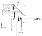
- the mirror array 80 includes a base member 80A having a plane (hereinafter referred to as a reference plane for convenience) that forms 45 degrees ( ⁇ / 4) with respect to the XY plane and the XZ plane, and a base member 80A.
- a drive unit 87 (not shown in FIG. 4; see FIG. 11) including M actuators (not shown) that individually drive 81 p and q .
- the mirror array 80 can substantially form a large reflecting surface parallel to the reference surface by adjusting the inclination of the multiple mirror elements 81 p, q with respect to the reference surface.
- Each mirror element 81 p, q of the mirror array 80 is configured to be rotatable in parallel to the rotation axis, for example, in one diagonal of each mirror element 81 p, q, a predetermined inclination angle with respect to the reference plane of the reflecting surface An arbitrary angle within the angle range can be set.
- the angle of the reflecting surface of each mirror element is measured by a sensor that detects the rotation angle of the rotating shaft, for example, a rotary encoder 83 p, q (not shown in FIG. 4, refer to FIG. 11).
- the drive unit 87 includes, for example, an electromagnet or a voice coil motor as an actuator, and each mirror element 81 p, q is driven by the actuator and operates with a very high response.
- each of the mirror elements 81p and q illuminated by the annular parallel beam from the light source system 510 has a reflected beam in a direction according to the inclination angle of its reflecting surface. (Parallel beam) is emitted and incident on the condensing optical system 82 (see FIG. 6).
- the cross-sectional shape (cross-sectional intensity distribution) of the parallel beam may be different from the annular shape, or the beam cross-sectional intensity conversion optical system 78 may not be provided.
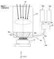
- Condensing optical system 82 has a numerical aperture of N.P. A. Is an optical system with a high NA of 0.5 or more, preferably 0.6 or more, and low aberration. Since the condensing optical system 82 has a large aperture, low aberration, and high NA, a plurality of parallel beams from the mirror array 80 can be condensed on the rear focal plane. Although details will be described later, the beam irradiation unit 520 can condense the beam emitted from the condensing optical system 82 into, for example, a spot shape or a slit shape. Further, the condensing optical system 82 is configured by one or a plurality of large-diameter lenses (in FIG.
- the beam condensed by the condensing optical system 82 according to the present embodiment is extremely sharp and has a high energy density, which directly leads to an increase in processing accuracy of additional processing by modeling.
- a workpiece W having a beam and a modeling target surface TAS at the upper end by moving the table 12 in a scanning direction parallel to the XY plane (in FIG. 4, as an example, the Y-axis direction), a workpiece W having a beam and a modeling target surface TAS at the upper end.
- modeling processing
- the table 12 may be moved in at least one of the X axis direction, the Z axis direction, the ⁇ x direction, the ⁇ y direction, and the ⁇ z direction while the table 12 is moving in the Y axis direction. Needless to say.
- the powdery modeling material (metal material) supplied by the material processing unit 530 is melted by the energy of the laser beam. Therefore, as described above, if the total amount of energy taken in by the condensing optical system 82 increases, the energy of the beam emitted from the condensing optical system 82 increases, and the amount of metal that can be dissolved per unit time increases. Accordingly, if the supply amount of the modeling material and the speed of the table 12 are increased, the throughput of modeling processing by the beam modeling system 500 is improved.
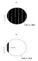
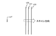
- a slit-shaped beam irradiation region (hereinafter referred to as a single character region (FIG. 9B). Is formed on a surface (hereinafter referred to as a modeling surface) MP (for example, see FIGS. 4 and 9A) on which the modeling target surface TAS is to be aligned, and the one-character area LS is formed.
- Modeling can be performed while relatively scanning the workpiece W in a direction perpendicular to the longitudinal direction of a beam to be formed (hereinafter referred to as a single character beam). Thereby, an extremely large area (for example, an area of several times to several tens of times) can be processed at a stroke as compared with the case of scanning a workpiece with a spot-like beam.
- the above-described modeling surface MP is the rear focal plane of the condensing optical system 82 (see, for example, FIGS. 4 and 9A), but the modeling surface is the rear surface. A surface near the side focal plane may be used.
- the modeling surface MP is perpendicular to the optical axis AX on the exit side of the condensing optical system 82, but may not be perpendicular.
- the incident angles of a plurality of parallel beams incident on the condensing optical system 82 A technique for controlling the distribution can be employed.
- the condensing position on the side focal plane (condensing surface) is determined.
- the incident angle is: a.
- a two-dimensional orthogonal coordinate system (X, Y) orthogonal to the optical axis AX is set on the pupil plane PP and the point on the optical axis AX is set as the origin, it is incident on the pupil plane PP.
- a beam incident perpendicularly to the pupil plane PP of the condensing optical system 82 (parallel to the optical axis) is incident on the optical axis AX with respect to the condensing optical system 82.
- a beam slightly tilted (with respect to the optical axis AX) is condensed at a position slightly deviated from the optical axis AX.
- the incident angles (incident directions) of the plurality of parallel beams LB incident on the pupil plane PP of the condensing optical system 82 are arbitrarily changed.
- the incident angle (incident direction) is set to an angle ⁇ and an angle ⁇ .
- the incident angle (incident direction), and the incident angle (incident direction) of the parallel beam incident on the pupil plane PP is not limited to control using the angles ⁇ and ⁇ as parameters. Needless to say, the.
- the condensing optical system 82 of this embodiment has a configuration in which the pupil plane (incidence pupil) PP and the front focal plane coincide, the incident angles of a plurality of parallel beams LB using the mirror array 80 are used.
- the converging position of the plurality of parallel beams LB can be controlled accurately and simply, but the pupil plane (incident pupil) of the condensing optical system 82 and the front focal plane are not matched. May be.
- the incident angle can be controlled to change the position of the irradiation region.
- the area of the target surface where the target site for modeling is set is not always a flat surface. That is, relative scanning of one character beam is not always possible.
- the boundary is slanted, narrowed, or has an R, making it difficult to apply relative scanning of a single character beam. It is. For example, with a wide brush, it is difficult to paint in such a place, so a narrow brush and a thin pencil are needed, so to speak, in real time and continuously, freely I want to use a brush and a thin pencil separately.
- the width of the irradiation area of the beam in the scanning direction can be changed, or the size of the irradiation area ( For example, there is a demand for changing the length of one character beam), the number, or the position (position of the irradiation point of the beam).
- the mirror array 80 is employed, and the control device 600 operates each mirror element 81 p, q with a very high response so that a plurality of light incident on the pupil plane PP of the condensing optical system 82 is obtained.
- the incident angle of the parallel beam LB is controlled.
- the intensity distribution of the beam on the modeling surface MP is set or changed.
- the control device 600 is on the modeling surface MP during the relative movement between the beam and the target surface TAS (the surface on which the modeling target portion TA is set, which is the surface on the workpiece W in this embodiment). It becomes possible to change the intensity distribution of the beam, for example, at least one of the shape, size and number of the irradiation region of the beam.
- control device 600 can change the intensity distribution of the beam on the modeling surface MP continuously or intermittently. For example, it is possible to continuously or intermittently change the width of one character area in the relative movement direction during the relative movement of the beam and the target surface TAS.
- the control device 600 can also change the intensity distribution of the beam on the modeling surface MP according to the relative position between the beam and the target surface TAS.
- the control device 600 can also change the intensity distribution of the beam on the modeling surface MP according to the required modeling accuracy and throughput.
- the control device 600 detects the state of each mirror element (here, the inclination angle of the reflecting surface) using the rotary encoder 83 p, q described above, and thereby the state of each mirror element is determined. Since the monitoring is performed in real time, the inclination angle of the reflecting surface of each mirror element of the mirror array 80 can be accurately controlled.
- the material processing unit 530 includes a nozzle unit 84 having a nozzle member (hereinafter abbreviated as a nozzle) 84 a provided below the exit surface of the condensing optical system 82, and a nozzle unit 84.
- a material supply device 86 connected via a pipe 90a and a plurality of, for example, two powder cartridges 88A and 88B connected to the material supply device 86 via a pipe, respectively. 7 shows a portion below the condensing optical system 82 in FIG. 4 as viewed from the ⁇ Y direction.
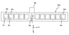
- the nozzle unit 84 extends in the X-axis direction below the condensing optical system 82 and supports at least one supply port for supplying the powder of the modeling material and both ends in the longitudinal direction of the nozzle 84a. , And a pair of support members 84 b and 84 c each having an upper end connected to the housing of the condensing optical system 82.
- One support member 84b is connected to one end (lower end) of a material supply device 86 via a pipe 90a, and a supply path for communicating the pipe 90a and the nozzle 84a is formed therein.
- the nozzle 84a is disposed immediately below the optical axis of the condensing optical system 82, and a plurality of supply ports to be described later are provided on the lower surface (bottom surface).
- the nozzle 84a is not necessarily arranged on the optical axis of the condensing optical system 82, and may be arranged at a position somewhat shifted from the optical axis to one side in the Y-axis direction.
- the other ends (upper ends) of the material supply device 86 are connected to pipes 90b and 90c as supply paths to the material supply device 86, and powder cartridges 88A and 88B are connected to the material supply device 86 via the pipes 90b and 90c, respectively. It is connected.
- One powder cartridge 88A contains a powder of a first modeling material (for example, titanium).
- the other powder cartridge 88B contains powder of the second modeling material (for example, stainless steel).
- the modeling apparatus 100 includes two powder cartridges for supplying two types of modeling materials to the material supply apparatus 86, but the modeling apparatus 100 may include only one powder cartridge.
- the supply of powder from the powder cartridges 88A and 88B to the material supply device 86 may have a function of forcibly supplying the powder to the material supply device 86 in each of the powder cartridges 88A and 88B.
- the material supply device 86 has a function of sucking powder from one of the powder cartridges 88A and 88B by using a vacuum, in addition to a function of switching the pipes 90b and 90c.
- the material supply device 86 is connected to the control device 600 (see FIG. 11). At the time of modeling, the control device 600 switches between the pipes 90b and 90c using the material supply device 86, and the first modeling material (for example, titanium) powder from the powder cartridge 88A and the second from the powder cartridge 88B.
- the powder of the modeling material (for example, stainless steel) is alternatively supplied to the material supply device 86, and either one of the powders of the modeling material is supplied from the material supply device 86 to the nozzle 84a via the pipe 90a.
- the first modeling material from the powder cartridge 88A and the second modeling material from the powder cartridge 88B are supplied to the material supply device 86 at the same time if necessary. It is good also as a structure which can supply the mixture of two modeling materials to the nozzle 84a via the piping 90a.
- a nozzle that can be connected to the powder cartridge 88A and another nozzle that can be connected to the powder cartridge 88B are provided below the condensing optical system 82, and powder is supplied from either one of the nozzles during modeling, or both nozzles. You may supply powder from.
- control device 600 can adjust the supply amount of the modeling material supplied from the powder cartridges 88A and 88B to the nozzle 84a via the material supply device 86 per unit time. For example, by adjusting the amount of powder supplied from at least one of the powder cartridges 88A and 88B to the material supply device 86, the supply amount of the modeling material supplied to the nozzle 84a via the material supply device 86 per unit time. Can be adjusted. For example, it is possible to adjust the supply amount per unit time of the modeling material supplied to the nozzle 84a by adjusting the vacuum level used for supplying the powder from the powder cartridges 88A and 88B to the material supply device 86. It is. Alternatively, a valve for adjusting the amount of powder supplied from the material supply device 86 to the pipe 90a may be provided to adjust the supply amount per unit time of the modeling material supplied to the nozzle 84a.
- N supply ports 91 i 1 to N
- FIG. 8 for convenience of illustration, twelve supply ports 91 i are illustrated as an example, and both are illustrated so that the relationship between the supply port and the opening / closing member can be understood.
- more than 12 supply ports are formed, and the partition portion between adjacent supply ports is narrower.
- the number of supply ports may be any number as long as the supply ports are arranged over substantially the entire length in the longitudinal direction of the nozzle 84a.
- the supply port may be a single slit-like opening over almost the entire length in the longitudinal direction of the nozzle 84a.
- Closing member 93 i can be driven slide in the + Y direction and the -Y direction, the supply port 91 i, Open and close.
- the opening / closing member 93 i is not limited to the slide drive, and may be configured to be rotatable in the tilt direction with the one end portion as the center.
- Each opening / closing member 93 i is driven and controlled by the control device 600 via an actuator (not shown).
- the control device 600 supplies a plurality of, for example, N supplies according to the setting (or change) of the intensity distribution of the beam on the modeling surface, for example, the shape, size, and arrangement of the irradiation region of the beam formed on the modeling surface.
- Each of the ports 91 i is controlled to be opened and closed using each opening and closing member 93 i . Thereby, the supply operation of the modeling material by the material processing unit 530 is controlled.
- the modeling material can be supplied from only a part of a plurality of, for example, N supply ports 91 i .
- the control device 600 includes a supply amount control per unit time of the building material to be supplied to the nozzle 84a through the material supply device 86 described above, by at least one of the opening and closing control using any of the opening and closing member 93 i It is also possible to adjust the supply amount per unit time of the modeling material from the supply port 91 i opened and closed by the opening and closing member 93 i .
- the control device 600 controls the intensity distribution of the beam on the modeling surface, for example, from any supply port 91 i according to the setting (or change) of the shape, size, arrangement, etc. of the irradiation region of the beam formed on the modeling surface.
- the supply amount per unit time of the modeling material is determined.
- the control device 600 determines the supply amount per unit time from each supply port 91 i based on, for example, the width in the scan direction of the one character area described above.
- the control device 600 may adjust the opening degree of each supply port by each opening / closing member 93 i according to, for example, the width in the scanning direction of the one character region described above.
- At least one supply port for supplying the powder of the modeling material may be movable.
- one slit-like supply port extending in the X-axis direction is formed on the lower surface of the nozzle 84a, and the nozzle 84a is disposed on at least one of the X-axis direction and the Y-axis direction with respect to the pair of support members 84b and 84c, for example.
- the control device 600 has a movable configuration, and the control device 600 changes the intensity distribution of the beam on the modeling surface, that is, the nozzle 84a having the supply port formed on the lower surface in accordance with the change in the shape, size, and position of the irradiation region of the beam. You may move.
- the nozzle 84a may be movable in the Z-axis direction.
- the nozzle 84a can be moved in at least one of the X-axis direction and the Y-axis direction in the XY plane with respect to the main body part, for example, in the XY plane, and at least two movable members having a supply port formed on the bottom surface thereof.
- the control device 600 may move at least a part of the movable member according to a change in the intensity distribution of the beam on the modeling surface. Also in this case, at least a part of the movable member may be movable in the Z-axis direction.
- a configuration may be adopted in which one of the plurality of supply ports and another supply port are relatively movable.
- the position of the one supply port in the Y-axis direction may be different from the position of the other one supply port in the Y-axis direction.
- the position of the one supply port in the Z-axis direction may be different from the position of the other supply port in the Z-axis direction.
- the movement of at least one supply port may be performed not only for the setting or change of the beam intensity distribution but also for other purposes.
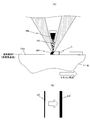
- the plurality of supply ports 91 i provided in the nozzle 84 a are arranged at equal intervals over the entire length of the nozzle 84 a in the X-axis direction perpendicular to the optical axis of the condensing optical system 82 and adjacent to each other. There is only a slight gap between the supply ports 91 i . For this reason, as shown by the black arrow in FIG. 9A, the powdery modeling material PD is parallel to the optical axis AX of the condensing optical system 82 from each of the plurality of supply ports 91 i of the nozzle 84a.
- the modeling material PD is supplied to the one character region LS (one character beam irradiation region) immediately below the optical axis AX of the condensing optical system 82.
- supply of the modeling material PD from the nozzle 84a can be performed by utilizing the weight of the modeling material PD or by jetting with a slight jet pressure. Therefore, a complicated mechanism such as a gas flow generation mechanism for guiding the supply of the modeling material as in the case of supplying the modeling material from an oblique direction with respect to the modeling target surface is unnecessary.
- the ability to supply a modeling material perpendicularly to a workpiece at a close distance as in the present embodiment is extremely advantageous in ensuring processing accuracy in modeling.
- a gas supply port may be provided in the nozzle 84a.
- the gas supplied from the gas supply port may flow in order to guide the supply of the modeling material, or may flow a gas that contributes to another purpose, for example, modeling.
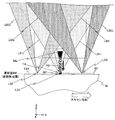
- the reflected beam from the mirror array 80 is a partial region (partial region having a large NA) in the vicinity of the periphery of the condensing optical system 82.
- the shaping surface MP (the main surface of the condensing optical system 82 through the peripheral area away from the optical axis of the terminal lens located at the exit end of the condensing optical system 82, that is, the exit end of the beam irradiation unit 520.
- the light is condensed on the rear focal plane of the condensing optical system 82 (see FIG. 4).
- a single character beam is formed only by the light passing through the vicinity of the periphery of the same condensing optical system 82. For this reason, it is possible to form a high-quality beam spot as compared with the case where a beam spot (laser spot) is formed by condensing light through different optical systems in the same region. Further, in the present embodiment, it is possible to limit the irradiation of the beam to the nozzle 84 a provided below the center of the exit surface (lower end surface) of the condensing optical system 82.
- the present embodiment it is possible to use all of the reflected beam from the mirror array 80 for spot formation, and the beam is provided at a portion corresponding to the nozzle 84a on the incident surface side of the condensing optical system 82. There is no need to provide a light shielding member or the like for restricting the irradiation to 84a. For this reason, the mirror array 80 is illuminated with an annular parallel beam.
- the optical member located at the exit end of the condensing optical system 82 has an optical surface formed at least in a region away from the optical axis of the exit side surface, and a modeling surface (rear focal plane) is interposed through the optical surface. It is only necessary that the beam can be condensed. Therefore, in the optical member, in the region including the optical axis, at least one of the exit surface and the incident surface may be a plane perpendicular to the optical axis of the condensing optical system 82, or the region including the optical axis. A hole may be formed in the hole.
- the optical member positioned at the exit end of the condensing optical system 82 may be configured by a donut-shaped condensing lens having a hole in the central region including the optical axis.
- a limiting member 85 indicated by a two-dot chain line in FIG. 7 is provided on the incident surface side (for example, the pupil plane PP) of the condensing optical system 82. It may be provided.
- the limiting member 85 limits the incidence of the beam from the condensing optical system 82 on the nozzle 84a.
- a light shielding member may be used, or a neutral density filter or the like may be used.
- the parallel beam incident on the condensing optical system 82 may be a parallel beam having a circular cross section or an annular parallel beam. In the latter case, since the beam is not irradiated on the limiting member 85, all the reflected beams from the mirror array 80 can be used for spot formation.
- the condensing optical system It is not always necessary to completely shield the beam incident on the nozzle 84a from the condensing optical system 82, but in order to prevent the beam from the condensing optical system 82 from entering the nozzle 84a, the condensing optical system.
- the beam may be emitted only from the peripheral region (for example, two arc regions) separated from both sides of the optical axis in the Y-axis direction on the exit surface of the terminal lens 82.
- the water shower nozzle 540 (see FIG. 11) is used for so-called quenching.
- the water shower nozzle 540 has a supply port for supplying a cooling liquid (cooling water), and jets the cooling liquid onto the object to be cooled.
- the water shower nozzle 540 is connected to the control device 600 (see FIG. 11).
- the control device 600 controls the light source unit 60 to adjust the thermal energy of the beam from the beam irradiation unit 520 to a value appropriate for quenching.
- the control device 600 can perform quenching by irradiating the surface of the workpiece with a beam to increase the temperature, and then injecting a cooling liquid into the high temperature portion via the water shower nozzle 540 to rapidly cool the workpiece.
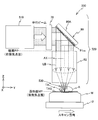
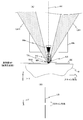
- FIG. 9A showing an enlarged view of the circle A in FIGS. 4 and 4, it passes through the vicinity of the peripheral portion of the condensing optical system 82.
- Beams passing through the optical path on the + Y side and -Y side of the nozzle 84a (front and rear in the scanning direction of the workpiece W (table 12)) (shown as beams LB1 1 and LB1 2 for convenience in FIG. 9A) Is condensed directly below the nozzle 84a, and a one-character region LS having a longitudinal direction in the X-axis direction (the direction orthogonal to the paper surface in FIG. 9A) is formed on the modeling surface (see FIG. 9B).
- the powdered modeling material PD passes along the Z axis parallel to the optical axis AX of the condensing optical system 82 via the plurality of supply ports 91 i of the nozzle 84a (optical axis). (Along the XZ plane including AX). As a result, a linear molten pool WP extending in the X-axis direction is formed directly below the nozzle 84a. The molten pool WP is formed while scanning the table 12 in the scanning direction (+ Y direction in FIG. 9A).
- the beams LB1 1 and LB1 2 shown in FIG. 9A are different from each other in the mirror elements 81 p. It may be a separate parallel beam reflected at q and incident on the pupil plane PP of the condensing optical system 82 at a different incident angle, or may be a part of the same parallel beam, for example, a parallel beam having a ring-shaped cross section. Also good.
- the condensing density (energy density) of the beams is increased. Accordingly, by increasing the supply amount of powder (modeling material) per unit time and increasing the scanning speed of the target surface TAS accordingly, the thickness of the formed bead BE layer is kept constant, and the throughput is increased. Can be kept at a high level.
- the thickness of the bead BE layer to be formed can be kept constant by using other adjustment methods as well as the adjustment method.
- the laser output (the amount of energy of the laser beam) of at least one of the plurality of laser units 70 may be adjusted according to the width in the X-axis direction, the width in the Y-axis direction, or both widths of one character beam.
- the number of parallel beams LB incident on the condensing optical system 82 from the mirror array 80 may be changed. In this case, the throughput is somewhat lower than the adjustment method described above, but the adjustment is simple.
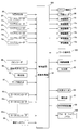
- FIG. 11 is a block diagram showing the input / output relationship of the control device 600 that mainly configures the control system of the modeling apparatus 100.
- the control device 600 includes a workstation (or a microcomputer) and the like, and comprehensively controls each component of the modeling device 100.
- the basic function of the modeling apparatus 100 is to add a desired shape to an existing part (work) by three-dimensional modeling.
- the workpiece is put into the modeling apparatus 100, and after a desired shape is accurately added, the workpiece is unloaded from the modeling apparatus 100. At this time, the actual shape data of the added shape is sent from the device to an external device, for example, a host device.
- a series of operations performed by the modeling apparatus 100 is roughly as follows.
- the table 12 is at a predetermined loading / unloading position, the workpiece is loaded on the table 12 by the workpiece transfer system 300.
- the table 12 on which the workpiece W is mounted is moved below the measurement system 400 by the control device 600.
- the table 12 is moved by the control device 600 controlling the planar motor 26 based on the measurement information of the position measurement system 28 and driving the slider 10 in the X-axis direction (and Y-axis direction) on the base BS. Done. During this movement, the above-described reference state is maintained on the table 12.
- the control device 600 uses the measurement system 400 to store the position information (shape information in the present embodiment) in at least a part of the target surface TAS on the workpiece W on the table 12 in the reference state in the three-dimensional space. Measurement is performed. Thereafter, based on this measurement result, the position of the target surface TAS on the workpiece W in the direction of 6 degrees of freedom can be managed by open loop control on the table coordinate system (reference coordinate system).
- the table 12 on which the workpiece W on which measurement of at least a part of the shape information of the target surface TAS has been completed is moved by the control device 600 to the lower side of the beam shaping system 500.
- the control device 600 converts the 3D CAD data of the shape to be added by the additional processing (the shape obtained by removing the shape of the workpiece to be subjected to the additional processing from the shape of the object created after the additional processing) to the data for three-dimensional modeling.
- the data is converted into STL (Stereo-Lithography) data, and data of each layer sliced in the Z-axis direction is generated from the three-dimensional STL data.
- the control device 600 controls the moving system 200 and the beam shaping system 500 to perform additional processing of each layer on the workpiece based on the data of each layer, thereby forming the above-described one character region and the nozzle 84a for one character beam.
- the formation of the linear (slit-shaped) molten pool by supplying the modeling material from is repeatedly performed for each layer while scanning the table 12 in the scanning direction.
- the control of the position and orientation of the target surface on the workpiece during the additional machining is performed in consideration of the shape information of the target surface measured previously.
- the target surface (for example, the upper surface) TAS on which the target portion TA for the additional processing of the workpiece W is set is perpendicular to the optical axis of the condensing optical system 82 by adjusting the tilt of the table 12.
- the surface is a flat surface (a surface parallel to the XY plane)
- modeling with the scanning operation of the table 12 is performed.
- the target surface on which the target part for workpiece additional machining is set is not necessarily a plane that can use a single character beam.
- the modeling apparatus 100 according to the present embodiment includes the moving system 200 that can arbitrarily set the position of the table 12 on which the workpiece is mounted in the direction of 6 degrees of freedom.
- the control device 600 controls the moving surface 200 and the beam irradiation unit 520 of the beam forming system 500 based on the three-dimensional shape of the workpiece measured using the measuring system 400, and the forming surface MP.
- the width in the X-axis direction of the beam irradiation region on the modeling surface MP to the extent that the target surface (for example, the upper surface) on the workpiece W aligned with the surface of the modeling surface MP can be regarded as a flat that can be additionally processed in the irradiation region of the beam on the modeling surface MP
- the supply port 91 i is opened / closed via the open / close members 93 i of the nozzle 84 a, and the modeling material is supplied from the necessary supply port to the beam irradiated to the irradiation region.
- additional processing is performed with a beam having a small width in the X-axis direction of the irradiation region on the modeling surface, and a relatively large area plane is formed. Additional processing (bead formation) may be performed on the plane using a single character beam having a larger width in the X-axis direction of the irradiation region.
- Additional processing may be performed on the plane using a single character beam having a larger width in the X-axis direction of the irradiation region on the surface MP.
- control device 600 moves the table 12 on which the additional workpiece W has been mounted to the loading / unloading position described above.
- the control device 600 instructs the workpiece transfer system 300 to unload the workpiece.
- the workpiece transfer system 300 takes out the workpiece W that has undergone additional processing from the table 12 and transfers it to the outside of the modeling apparatus 100.
- the control device 600 sets the table 12 of the mobile system 200 to the reference state.
- the moving system 200 stands by in preparation for loading the next workpiece at the loading / unloading position.
- the modeling apparatus 100 As described above in detail, according to the modeling apparatus 100 according to the present embodiment and the modeling method performed in the modeling apparatus 100, at least one of the plurality of supply ports 91 i of the nozzle 84a at the time of modeling,
- the modeling material PD is supplied along the optical axis AX on the exit surface side of the condensing optical system 82 or an axis parallel to the optical axis AX, that is, along the vertical direction, and is ejected from the exit surface of the condensing optical system, A beam LB passing through an optical path inclined with respect to the optical axis AX is irradiated to the modeling material PD.
- the condensing optical system 82 can be an optical system having a large aperture, a high NA (for example, NA is 0.5 or more) and a low aberration. Multiple parallel beams from the array 80 can be collected on the back focal plane. Further, since the condensing optical system 82 is composed of one or a plurality of large-diameter lenses, the area of incident light can be increased, and the beam condensed by the condensing optical system 82 is It is extremely sharp and has a high energy density, which directly leads to an increase in processing accuracy of additional processing by modeling. In addition, since the modeling material can be supplied perpendicularly to the target surface at a close distance, it is extremely advantageous for ensuring the processing accuracy in modeling.
- a spot-like or slit-like beam for example, a single character beam is formed only by light passing through a portion near the periphery of the same condensing optical system 82. For this reason, it is possible to form a high-quality beam spot as compared with the case where a beam spot (laser spot) is formed by condensing light through different optical systems in the same region.
- the modeling apparatus 100 according to the present embodiment and the modeling method performed by the modeling apparatus 100, it is possible to form a three-dimensional modeled object with good processing accuracy on the target surface.
- the intensity distribution of the beam in the modeling surface MP is determined only before the modeling is started by relative movement between the beam and the target surface TAS.
- it can be changed continuously if necessary, and depending on the relative position between the target surface TAS and the beam, the required modeling accuracy and throughput can be obtained. It can be changed according to As a result, the modeling apparatus 100 can form a modeled object on the target surface TAS of the workpiece W with high processing accuracy and high throughput, for example, by rapid prototyping.
- the powder from the nozzle 84a is applied to the single character beam described above.
- a linear shaped molten pool WP is formed immediately below the nozzle 84a by supplying the shaped molding material PD, and the molten pool WP is formed while scanning the table 12 in the scanning direction (+ Y direction in FIG. 4).
- FIG. 12 (B) a shape that cannot be generated unless the spot-like beam is reciprocated dozens of times as shown in FIG. 12 (A).
- the table 12 can be generated by several reciprocations for one character beam. According to the present embodiment, it becomes possible to form a modeled object on the target surface of the workpiece in a much shorter time than in the case of modeling with a conventional spot-shaped beam, that is, modeling with a single stroke. That is, also in this respect, throughput can be improved.
- the modeling surface of the condensing optical system 82 is changed by changing the inclination angle of the reflecting surface of each mirror element of the mirror array 80. Since the intensity distribution of the beam is changed, at least one of the position, number, size, and shape of the irradiation area of the beam in the modeling surface can be easily changed as the intensity distribution change. . Therefore, for example, by setting the irradiation area in a spot shape, slit shape (line shape), etc., and performing the three-dimensional modeling on the target surface on the workpiece by the method described above, a highly accurate three-dimensional structure can be formed. It becomes possible.
- the modeling apparatus 100 includes a plurality of, for example, two powder cartridges 88A and 88B, and each of the powder cartridges 88A and 88B includes a first modeling material (for example, titanium) powder, a first The powder of 2 modeling materials (for example, stainless steel) is accommodated.
- the control device 600 switches the powder supply path to the nozzle unit 84 using the material supply device 86, that is, the pipes 90b and 90c.
- the powder of the first modeling material (for example, titanium) from the powder cartridge 88A and the powder of the second modeling material (for example, stainless steel) from the powder cartridge 88B are alternatively supplied to the nozzle unit 84.
- the joining shape of different materials can be easily generated by simply switching the powder material supplied by the control device 600 according to the site.
- the switching can be performed almost instantaneously.
- an irradiation area of a single linear beam is formed by the beam shaping system 500, and the workpiece W is scanned in the scanning direction (for example, the Y-axis direction) with respect to the one character beam.
- the intensity distribution of the beam on the shaping surface MP can be freely set by appropriately distributing the incident angles of the plurality of parallel beams LB incident on the condensing optical system 82. Can be changed. Therefore, in the modeling apparatus 100, at least one of the position, number, size, and shape of the beam irradiation area on the modeling surface MP can be changed.
- the beam irradiation area for example, one character area, three It is also possible to form a row region, a missing single character region, etc. (see FIG. 10).
- FIG. 13 shows a state in which additional processing is performed on the workpiece W using three one-character beams that are respectively irradiated on the three one-character areas constituting the three-row area described above as an example.
- beams LB1 1 and LB1 2 that pass through the vicinity of the peripheral portion of the condensing optical system 82 and pass through the front and rear optical paths in the scanning direction of the workpiece W (table 12) with respect to the nozzle 84a.
- a slit-shaped (line-shaped) first first character region LS1 having a longitudinal direction in the X-axis direction (the direction orthogonal to the paper surface in FIG.
- the target surface TAS in which the target part TA of the workpiece W is set is aligned with the modeling surface MP. Further, the beams LB2 1 and LB2 2 that pass through the vicinity of the peripheral edge of the condensing optical system 82 and pass through the optical path on the rear side in the scanning direction with respect to the nozzle 84a are condensed and rearward in the scanning direction of the first first character area LS1.
- a second character region LS2 extending in the X-axis direction and having the same length as the first character region LS1 is formed at a position that is a predetermined distance away from the first character region LS1. Further, the beams LB3 1 and LB3 2 that pass through the vicinity of the peripheral edge of the condensing optical system 82 and pass through the optical path in the scanning direction with respect to the nozzle 84a are collected, and the first one character region LS1 is moved forward in the scanning direction.
- a third character region LS3 extending in the X-axis direction is formed at a position that is a predetermined distance away from the first character region LS1 in parallel with the first character region LS1.
- FIG. 14 shows the relationship between the three one-character areas LS1, LS2, and LS3 shown in FIG. 13 and the scan direction in the XY plane.
- the beams LB1 1 , LB1 2 , LB2 1 , LB2 2 , LB3 1 , and LB3 2 shown in FIG. 13 are schematically shown, and the optical path of the at least one beam incident on each character region and the beam
- the number and the like can be set and changed by controlling the mirror array 80, for example.
- one character beam formed in the first one character region LS1 located in the center of the scanning direction of the table 12 among the three one character regions LS1, LS2, LS3 (hereinafter referred to as the first one character beam for convenience).
- the powdery modeling material PD is supplied from the nozzle 84a, a linear molten pool WP is formed immediately below the plurality of supply ports of the nozzle 84a, and the formation of the molten pool WP is the work W (table 12).
- the one character beam forming the second one character region LS2 (hereinafter referred to as the second one character beam for convenience) formed behind the scanning direction (backward in the traveling direction) of the table 12 with respect to the first one character region LS1 is shaped as an example. Before being performed, it plays a role of preheating (heating to a moderate temperature) the surface of the workpiece W (target portion of the target surface). If such preheating is not performed, rapid cooling of the molten metal occurs due to a large temperature difference between the high-temperature metal melted by the laser beam and the low-temperature workpiece (target surface), and it instantly solidifies and becomes a loose lump. Become.
- One character beam (hereinafter referred to as the third one character beam for convenience) forming the third one character region LS3 positioned in front of the table 12 in the scanning direction (forward in the traveling direction) with respect to the first one character region LS1 is, for example, the surface of the workpiece W It brings about the effect
- Surface polishing with a laser beam is well known as a general technique. However, good surface accuracy and surface roughness that cannot normally be obtained by one additional processing (modeling) are immediately polished with the third first character beam. This can be achieved.
- the above-described preheating (preheating) of the surface of the workpiece W, the molten pool and the bead for the workpiece are performed.
- laser polishing of the formed bead surface can be performed.
- the second one-character beam in the case of FIG. 13 is not limited to preheating and may be used for other purposes.
- the third first character beam may be used for purposes other than laser polishing.
- three nozzles are provided corresponding to the arrangement of the first, second, and third one character regions LS1, LS2, and LS3, and three are formed on the modeling surface of the workpiece W by the first, second, and third one character beams.
- Two linear molten pools having a predetermined width may be formed simultaneously.
- the surface temperature of the workpiece W is set to a moderate temperature before the third first character beam is shaped.
- the second first character beam adheres to the surface of the workpiece W and plays a role of laser polishing the surface of the metal material once solidified.
- the second first character beam used for preheating (preheating) the surface of the work W.
- the irradiation region (second one character region) and the third one character beam irradiation region (third one character region) used for laser polishing of the formed bead surface are formed apart from each other on the modeling surface.
- at least a part of the first one character region and the second one character region may overlap.
- at least one of the second one character region LS2 and the third one character region LS3 may be different from the first one character region LS1 in at least one of shape and size.
- the thickness of the molten pool is controlled by making the single character area as thin and sharp as possible, making use of the fact that the energy density of the beam irradiated to the single character area drops sharply when defocused.
- the explanation was given on the premise that usage was enhanced as much as possible.
- the thickness of the coating layer becomes very thin, and when adding a layer of the same thickness, additional processing (modeling) must be carried out by dividing it into more layers (overlapping many times). It has to be painted), which is disadvantageous in terms of productivity.
- the control device 600 changes the intensity distribution of the beam in the modeling surface according to the required modeling accuracy and throughput, specifically, the mirror elements 81 p and q of the mirror array 80. It is only necessary to control the tilt angle to make the width of one character area a little thicker.
- the one character area LS shown in FIG. 15B changes to one character area LS ′. In this way, the energy density change at the time of defocusing becomes gradual, and as shown in FIG. 15A, the thickness h of the high-energy area in the vertical direction is increased, and this makes it possible to perform one scan.
- the thickness of the layer that can be generated can be increased, and productivity can be improved.
- the modeling apparatus 100 is characterized in that it has a large number of conveniences and solutions that meet the demands of the actual processing site as compared with the conventional metal 3D printer. .
- the case where the mirror array 80 is used as the spatial light modulator has been described.
- a digital micromirror device (DMD (registered trademark)) manufactured by MEMS technology is used.
- DMD digital micromirror device
- MEMS microelectror device
- the surface of the large-area digital mirror device is irradiated with detection light, reflected light from a large number of mirror elements constituting the digital mirror device is received, and each mirror element is based on its intensity distribution.
- the detection system may detect the state of each of a large number of mirror elements based on image information obtained by imaging an image formed by the digital mirror device by the imaging means.
- the detection system 89 indicated by a virtual line in FIG. 11 may be used together with the rotary encoders 83 p and q .
- this detection system 89 for example, the reflected light from a large number of mirror elements 81p and q constituting the mirror array 80 is passed through a beam splitter disposed between the mirror array 80 and the condensing optical system 82.
- a detection system that receives light and detects the state of each mirror element 81 p, q based on the intensity distribution can be used.
- the detection system for example, a system having the same configuration as that disclosed in US Pat. No. 8,456,624 can be used.
- the mirror array 80 of a type that can change the inclination angle of the reflection surface of each mirror element 81p , q with respect to the reference surface is used, but the present invention is not limited to this.
- each mirror element does not necessarily have to be tiltable with respect to the reference plane.
- a mirror array that can be displaced in a direction perpendicular to the reference plane is disclosed in, for example, US Pat. No. 8,456,624.
- a mirror array of a type in which each mirror element can rotate around two mutually orthogonal axes parallel to the reference plane (that is, the tilt angle in two orthogonal directions can be changed) may be employed.
- Such a mirror array capable of changing the inclination angle in two orthogonal directions is disclosed in, for example, US Pat. No. 6,737,662. Even in these cases, the state of each mirror element can be detected using the detection system disclosed in the above-mentioned US Pat. No. 8,456,624.
- a detection system that irradiates the surface of the mirror array 80 with detection light and receives reflected light from a large number of mirror elements 81 p and q constituting the mirror array 80 may be used.
- a sensor that individually detects an inclination angle and an interval with respect to a reference plane (base) of each mirror element may be provided in the mirror array (optical device).
- the case where the intensity distribution of the beam on the modeling surface is changed by individually controlling the incident angles of the plurality of parallel beams incident on the pupil plane of the condensing optical system 82 has been described.
- the incident angles of the plurality of parallel beams incident on the pupil plane of the condensing optical system 82 may not be controllable (changeable). Therefore, when the incident angle of the parallel beam incident on the condensing optical system 82 is controlled using a mirror array as in the above embodiment, all mirror elements are in the state of the reflecting surface (the position and the inclination angle of the reflecting surface). At least one of them may not be changeable.
- the mirror array 80 is used to control the incident angles of a plurality of parallel beams incident on the condensing optical system 82, that is, to change the intensity distribution of the beam on the modeling surface.
- a spatial light modulator non-light emitting image display element
- the transmissive spatial light modulator include an electrochromic display (ECD) in addition to a transmissive liquid crystal display element (LCD).
- the reflective spatial light modulator includes a reflective liquid crystal display element, an electrophoretic display (EPD), electronic paper (or electronic ink), and a light diffraction light.
- An example is a bulb (Grating Light Valve).
- a mirror array a kind of spatial light modulator
- the condensing optical system 82 has a large aperture.
- a condensing optical system having a smaller than 0.5 may be used.
- the modeling apparatus 100 may include a sensor capable of arranging the light receiving unit on the rear focal plane of the condensing optical system 82 or in the vicinity thereof.
- a sensor capable of arranging the light receiving unit on the rear focal plane of the condensing optical system 82 or in the vicinity thereof.
- measurement may be performed in a state where the light receiving unit (for example, the table 12) of the sensor is stopped. You can go.
- the intensity distribution of the beam can be managed in consideration of the fluctuation factors such as thermal aberration of the condensing optical system 82. It becomes possible. Further, by controlling the mirror array 80 and the like based on the result, the beam intensity distribution on the rear focal plane of the condensing optical system 82 can be set to a desired state with high accuracy.
- the case where titanium or stainless steel powder is used as the modeling material is exemplified.
- powders other than metals such as iron powder and other metal powders, as well as powders such as nylon, polypropylene, and ABS are used.
- the modeling apparatus 100 according to the above embodiment can be applied to the case where a material other than powder, such as a filler wire used for welding, is used as the modeling material. In this case, however, a wire feeder or the like is provided in place of the powder supply system such as the powder cartridge and the nozzle unit.
- the present invention is not limited thereto, and the modeling material (powder) may be supplied from a direction inclined with respect to the optical axis AX. Moreover, you may supply modeling material (powder) from the direction inclined with respect to the perpendicular direction.
- the nozzle 84a included in the material processing unit 530 has a recovery port (suction port) for recovering the powdered modeling material that has not been melted together with the above-described modeling material supply port. You may do it.
- the usage of the modeling apparatus 100 according to the present embodiment is not limited to this, and on the table 12 as in a normal 3D printer or the like. It is also possible to generate a three-dimensional shape by modeling from nothing. In this case, it is nothing but to perform additional processing on the work "None".
- the control device 600 uses the mark detection system 56 (see FIG. 11) included in the measurement system 400 to form at least three places formed in advance on the table 12.
- the position information in the direction of six degrees of freedom of the target surface of the modeling set on the table 12 is obtained by optically detecting the alignment mark, and on the table 12 with respect to the beam (irradiation area) based on this result Three-dimensional modeling may be performed while controlling the position and orientation of the target surface.
- each processing device 600 controls each component of the moving system 200, the measurement system 400, and the beam modeling system 500 .
- a plurality of hardware units each including a processing unit such as a microprocessor may be used.
- each of the movement system 200, the measurement system 400, and the beam shaping system 500 may include a processing device, or the second one that controls two of the movement system 200, the measurement system 400, and the beam shaping system 500.
- a combination of one processing apparatus and a second processing apparatus that controls the remaining one system may be used.
- each processing device is responsible for a part of the function of the control device 600 described above.
- the modeling apparatus and the modeling method according to the present invention are suitable for forming a three-dimensional modeled object.
- Modeling material LB1 1 , LB1 2 ... Beam, LS ... One character area, LS1 ... First one character area, LS2 ... Second one character area, LS3 ... Third one character Area, MP ... modeling surface, TA ... target site, TAS ... target surface, W ... work, WP ... molten pool.
Landscapes
- Physics & Mathematics (AREA)
- Optics & Photonics (AREA)
- Engineering & Computer Science (AREA)
- Manufacturing & Machinery (AREA)
- Mechanical Engineering (AREA)
- Powder Metallurgy (AREA)
Abstract
L'invention concerne un dispositif de mise en forme comprenant : un système de mise en forme par des faisceaux comprenant une unité d'émission de faisceaux et une unité de traitement de matériau qui apporte un matériau de mise en forme (PD) exposé à des faisceaux (LB11, LB12) provenant de l'unité d'émission de faisceaux; et un dispositif de commande qui, sur la base de données tridimensionnelles d'un objet de forme tridimensionnelle, commande le système de mise en forme par des faisceaux et le système de déplacement d'une pièce (W) de façon telle qu'une zone cible (TA) sur une surface cible (TAS) est mise en forme par apport du matériau de mise en forme (PD) avec déplacement simultané des faisceaux (LB11, LB12) provenant de l'unité d'émission de faisceaux et de la surface cible (TAS) sur la pièce (W) les uns par rapport aux autres. Le matériau de mise en forme (PD) est apporté verticalement vers le bas à partir de l'orifice d'apport d'une buse (84a) disposée sur l'unité de traitement de matériau et le matériau de mise en forme est exposé aux faisceaux (LB11, LB12), qui sont émis à partir d'une surface d'émission d'un système optique de condensation de l'unité d'émission de faisceaux et qui passent le long du trajet optique incliné par rapport à l'axe optique (AX).
Priority Applications (1)
| Application Number | Priority Date | Filing Date | Title |
|---|---|---|---|
| PCT/JP2014/080152 WO2016075803A1 (fr) | 2014-11-14 | 2014-11-14 | Dispositif et procédé de mise en forme |
Applications Claiming Priority (1)
| Application Number | Priority Date | Filing Date | Title |
|---|---|---|---|
| PCT/JP2014/080152 WO2016075803A1 (fr) | 2014-11-14 | 2014-11-14 | Dispositif et procédé de mise en forme |
Publications (1)
| Publication Number | Publication Date |
|---|---|
| WO2016075803A1 true WO2016075803A1 (fr) | 2016-05-19 |
Family
ID=55953916
Family Applications (1)
| Application Number | Title | Priority Date | Filing Date |
|---|---|---|---|
| PCT/JP2014/080152 Ceased WO2016075803A1 (fr) | 2014-11-14 | 2014-11-14 | Dispositif et procédé de mise en forme |
Country Status (1)
| Country | Link |
|---|---|
| WO (1) | WO2016075803A1 (fr) |
Cited By (6)
| Publication number | Priority date | Publication date | Assignee | Title |
|---|---|---|---|---|
| JP2018149595A (ja) * | 2017-03-09 | 2018-09-27 | ツェーエル・シュッツレヒツフェアヴァルトゥングス・ゲゼルシャフト・ミト・べシュレンクテル・ハフツング | 三次元的な物体を付加的に製造するための装置 |
| WO2018181334A1 (fr) * | 2017-03-31 | 2018-10-04 | 株式会社ニコン | Système de modélisation et procédé de modélisation |
| CN110355364A (zh) * | 2018-03-26 | 2019-10-22 | 技术研究组合次世代3D积层造形技术综合开发机构 | 喷嘴及层叠造型装置 |
| JP2019218600A (ja) * | 2018-06-20 | 2019-12-26 | コマツNtc株式会社 | 3次元造形装置および3次元造形方法 |
| US20200164463A1 (en) * | 2017-05-01 | 2020-05-28 | Nikon Corporation | Processing apparatus and processing method |
| EP4462392A3 (fr) * | 2015-10-30 | 2024-12-18 | Seurat Technologies, Inc. | Système de combinaison de polarisations dans une fabrication additive |
Citations (6)
| Publication number | Priority date | Publication date | Assignee | Title |
|---|---|---|---|---|
| JPH02147184A (ja) * | 1988-11-28 | 1990-06-06 | Komatsu Ltd | レーザクラッディング方法及び装置 |
| JPH0810978A (ja) * | 1994-06-30 | 1996-01-16 | Mitsubishi Heavy Ind Ltd | レーザ加工ヘッド |
| JPH08156106A (ja) * | 1992-11-13 | 1996-06-18 | Japan Atom Energy Res Inst | 3次元物体製作法 |
| JPH09216083A (ja) * | 1995-12-05 | 1997-08-19 | Mitsubishi Heavy Ind Ltd | レーザー加工ヘッド及びレーザー加工方法 |
| JP2003251480A (ja) * | 2002-03-01 | 2003-09-09 | Toyota Motor Corp | レーザクラッド装置およびレーザ照射装置 |
| JP2003266189A (ja) * | 2002-03-15 | 2003-09-24 | Laserx:Kk | 溶接装置、溶接方法、および溶接された被溶接物を有する物品の製造方法 |
-
2014
- 2014-11-14 WO PCT/JP2014/080152 patent/WO2016075803A1/fr not_active Ceased
Patent Citations (6)
| Publication number | Priority date | Publication date | Assignee | Title |
|---|---|---|---|---|
| JPH02147184A (ja) * | 1988-11-28 | 1990-06-06 | Komatsu Ltd | レーザクラッディング方法及び装置 |
| JPH08156106A (ja) * | 1992-11-13 | 1996-06-18 | Japan Atom Energy Res Inst | 3次元物体製作法 |
| JPH0810978A (ja) * | 1994-06-30 | 1996-01-16 | Mitsubishi Heavy Ind Ltd | レーザ加工ヘッド |
| JPH09216083A (ja) * | 1995-12-05 | 1997-08-19 | Mitsubishi Heavy Ind Ltd | レーザー加工ヘッド及びレーザー加工方法 |
| JP2003251480A (ja) * | 2002-03-01 | 2003-09-09 | Toyota Motor Corp | レーザクラッド装置およびレーザ照射装置 |
| JP2003266189A (ja) * | 2002-03-15 | 2003-09-24 | Laserx:Kk | 溶接装置、溶接方法、および溶接された被溶接物を有する物品の製造方法 |
Cited By (17)
| Publication number | Priority date | Publication date | Assignee | Title |
|---|---|---|---|---|
| EP4462392A3 (fr) * | 2015-10-30 | 2024-12-18 | Seurat Technologies, Inc. | Système de combinaison de polarisations dans une fabrication additive |
| US11911959B2 (en) | 2017-03-09 | 2024-02-27 | Concept Laser Gmbh | Device for additive production of three-dimensional objects |
| JP2018149595A (ja) * | 2017-03-09 | 2018-09-27 | ツェーエル・シュッツレヒツフェアヴァルトゥングス・ゲゼルシャフト・ミト・べシュレンクテル・ハフツング | 三次元的な物体を付加的に製造するための装置 |
| JP2020073288A (ja) * | 2017-03-09 | 2020-05-14 | ツェーエル・シュッツレヒツフェアヴァルトゥングス・ゲゼルシャフト・ミト・べシュレンクテル・ハフツング | 三次元的な物体を付加的に製造するための方法 |
| EP3603853A4 (fr) * | 2017-03-31 | 2020-12-23 | Nikon Corporation | Système de modélisation et procédé de modélisation |
| WO2018181334A1 (fr) * | 2017-03-31 | 2018-10-04 | 株式会社ニコン | Système de modélisation et procédé de modélisation |
| CN110709195A (zh) * | 2017-03-31 | 2020-01-17 | 株式会社尼康 | 造型系统及造型方法 |
| JPWO2018181334A1 (ja) * | 2017-03-31 | 2020-02-06 | 株式会社ニコン | 造形システム及び造形方法 |
| JP7099443B2 (ja) | 2017-03-31 | 2022-07-12 | 株式会社ニコン | 造形システム及び造形方法 |
| US11691217B2 (en) * | 2017-05-01 | 2023-07-04 | Nikon Corporation | Laser processing device with optical device for changing cross-sectional intensity distribution of a beam at a pupil plane |
| US20200164463A1 (en) * | 2017-05-01 | 2020-05-28 | Nikon Corporation | Processing apparatus and processing method |
| US12296404B2 (en) | 2017-05-01 | 2025-05-13 | Nikon Corporation | Processing apparatus and processing method for removal processing with a light beam and having a workpiece position measurement system |
| CN110355364A (zh) * | 2018-03-26 | 2019-10-22 | 技术研究组合次世代3D积层造形技术综合开发机构 | 喷嘴及层叠造型装置 |
| JP7084224B2 (ja) | 2018-06-20 | 2022-06-14 | コマツNtc株式会社 | 3次元造形装置および3次元造形方法 |
| WO2019244416A1 (fr) * | 2018-06-20 | 2019-12-26 | コマツNtc株式会社 | Dispositif de modélisation en trois dimensions et procédé de modélisation en trois dimensions |
| JP2019218600A (ja) * | 2018-06-20 | 2019-12-26 | コマツNtc株式会社 | 3次元造形装置および3次元造形方法 |
| US12011761B2 (en) | 2018-06-20 | 2024-06-18 | Komatsu Ntc Ltd. | Three-dimensional shaping device and three-dimensional shaping method |
Similar Documents
| Publication | Publication Date | Title |
|---|---|---|
| JP6840540B2 (ja) | 造形装置 | |
| JP7255635B2 (ja) | 造形装置及び造形方法 | |
| JP6804298B2 (ja) | 造形装置 | |
| JP7061093B2 (ja) | 造形装置及び造形方法 | |
| WO2016075803A1 (fr) | Dispositif et procédé de mise en forme | |
| JP6886422B2 (ja) | 造形装置及び造形方法 | |
| JP2022106693A (ja) | 造形装置及び造形方法 | |
| JP2019137071A (ja) | 造形装置及び造形方法 | |
| JP6886423B2 (ja) | 造形装置及び造形方法 | |
| HK1234367A1 (en) | Shaping device and a shaping method | |
| HK1241800A1 (en) | Shaping device and a shaping method |
Legal Events
| Date | Code | Title | Description |
|---|---|---|---|
| 121 | Ep: the epo has been informed by wipo that ep was designated in this application |
Ref document number: 14905686 Country of ref document: EP Kind code of ref document: A1 |
|
| NENP | Non-entry into the national phase |
Ref country code: DE |
|
| 122 | Ep: pct application non-entry in european phase |
Ref document number: 14905686 Country of ref document: EP Kind code of ref document: A1 |
|
| NENP | Non-entry into the national phase |
Ref country code: JP |