WO2015158016A1 - Industrial treatment method and device for oil field wastes - Google Patents
Industrial treatment method and device for oil field wastes Download PDFInfo
- Publication number
- WO2015158016A1 WO2015158016A1 PCT/CN2014/076479 CN2014076479W WO2015158016A1 WO 2015158016 A1 WO2015158016 A1 WO 2015158016A1 CN 2014076479 W CN2014076479 W CN 2014076479W WO 2015158016 A1 WO2015158016 A1 WO 2015158016A1
- Authority
- WO
- WIPO (PCT)
- Prior art keywords
- oil
- dryer
- gas
- microwave
- treatment
- Prior art date
- Legal status (The legal status is an assumption and is not a legal conclusion. Google has not performed a legal analysis and makes no representation as to the accuracy of the status listed.)
- Ceased
Links
Classifications
-
- C—CHEMISTRY; METALLURGY
- C10—PETROLEUM, GAS OR COKE INDUSTRIES; TECHNICAL GASES CONTAINING CARBON MONOXIDE; FUELS; LUBRICANTS; PEAT
- C10B—DESTRUCTIVE DISTILLATION OF CARBONACEOUS MATERIALS FOR PRODUCTION OF GAS, COKE, TAR, OR SIMILAR MATERIALS
- C10B53/00—Destructive distillation, specially adapted for particular solid raw materials or solid raw materials in special form
-
- C—CHEMISTRY; METALLURGY
- C10—PETROLEUM, GAS OR COKE INDUSTRIES; TECHNICAL GASES CONTAINING CARBON MONOXIDE; FUELS; LUBRICANTS; PEAT
- C10B—DESTRUCTIVE DISTILLATION OF CARBONACEOUS MATERIALS FOR PRODUCTION OF GAS, COKE, TAR, OR SIMILAR MATERIALS
- C10B19/00—Heating of coke ovens by electrical means
-
- C—CHEMISTRY; METALLURGY
- C10—PETROLEUM, GAS OR COKE INDUSTRIES; TECHNICAL GASES CONTAINING CARBON MONOXIDE; FUELS; LUBRICANTS; PEAT
- C10G—CRACKING HYDROCARBON OILS; PRODUCTION OF LIQUID HYDROCARBON MIXTURES, e.g. BY DESTRUCTIVE HYDROGENATION, OLIGOMERISATION, POLYMERISATION; RECOVERY OF HYDROCARBON OILS FROM OIL-SHALE, OIL-SAND, OR GASES; REFINING MIXTURES MAINLY CONSISTING OF HYDROCARBONS; REFORMING OF NAPHTHA; MINERAL WAXES
- C10G1/00—Production of liquid hydrocarbon mixtures from oil-shale, oil-sand, or non-melting solid carbonaceous or similar materials, e.g. wood, coal
- C10G1/02—Production of liquid hydrocarbon mixtures from oil-shale, oil-sand, or non-melting solid carbonaceous or similar materials, e.g. wood, coal by distillation
-
- C—CHEMISTRY; METALLURGY
- C10—PETROLEUM, GAS OR COKE INDUSTRIES; TECHNICAL GASES CONTAINING CARBON MONOXIDE; FUELS; LUBRICANTS; PEAT
- C10G—CRACKING HYDROCARBON OILS; PRODUCTION OF LIQUID HYDROCARBON MIXTURES, e.g. BY DESTRUCTIVE HYDROGENATION, OLIGOMERISATION, POLYMERISATION; RECOVERY OF HYDROCARBON OILS FROM OIL-SHALE, OIL-SAND, OR GASES; REFINING MIXTURES MAINLY CONSISTING OF HYDROCARBONS; REFORMING OF NAPHTHA; MINERAL WAXES
- C10G1/00—Production of liquid hydrocarbon mixtures from oil-shale, oil-sand, or non-melting solid carbonaceous or similar materials, e.g. wood, coal
- C10G1/10—Production of liquid hydrocarbon mixtures from oil-shale, oil-sand, or non-melting solid carbonaceous or similar materials, e.g. wood, coal from rubber or rubber waste
-
- E—FIXED CONSTRUCTIONS
- E21—EARTH OR ROCK DRILLING; MINING
- E21B—EARTH OR ROCK DRILLING; OBTAINING OIL, GAS, WATER, SOLUBLE OR MELTABLE MATERIALS OR A SLURRY OF MINERALS FROM WELLS
- E21B21/00—Methods or apparatus for flushing boreholes, e.g. by use of exhaust air from motor
- E21B21/06—Arrangements for treating drilling fluids outside the borehole
- E21B21/063—Arrangements for treating drilling fluids outside the borehole by separating components
- E21B21/065—Separating solids from drilling fluids
- E21B21/066—Separating solids from drilling fluids with further treatment of the solids, e.g. for disposal
Definitions
- the present invention relates to the field of oil field waste treatment, and more particularly to an industrial treatment method for oil field waste and a device thereof.
- Oilfield waste generally refers to cuttings, water-based mud and oil-based mud generated during drilling, oily sludge and sediment generated during operation of oil and oil wells, soil contaminated with crude oil, and storage of crude oil in storage tanks. Tank bottom sediments, etc.
- oilfield waste also contains a large amount of toxic substances such as benzene, phenols, strontium and barium, salts and heavy metals such as copper, rhodium, chromium and mercury.
- These oilfield wastes are not easy to handle. It takes hundreds of years to completely decompose under natural conditions. It not only directly occupies land and space, but also seriously pollutes the air, soil and groundwater, which restricts the production and development of the petroleum industry to a certain extent.
- oilfield waste With the continuous improvement of the requirements of national environmental protection regulations and standards, environmental protection law enforcement has been continuously increased, and pollution control and resource utilization of oilfield wastes have become the focus of the industry's sustainable development.
- For the harmless and resource treatment of oilfield waste it now mainly includes quenching and tempering, separation and extraction treatment technology, curing treatment technology, incineration treatment technology, biological treatment technology, reinjection and blending technology, and pyrolysis treatment technology.
- pyrolysis technology uses electric heating or gas, fuel, and coal-fired heating methods, and its heat transfer is mainly through heat conduction, convection, and radiation.
- These conventional heating pyrolysis methods have low heating efficiency, and the processed products are required to meet national standards, and often consume more energy and have lower economic efficiency.
- the technical problem solved by the invention is to provide an industrial treatment method and device for oil field waste, which has good treatment effect, high energy utilization rate and good economy.
- the invention discloses an industrial treatment method for oil field waste, comprising the following steps:
- the gas is subjected to condensation separation and purification treatment to recover water and oil, and the recovered oil is used for steam heating or heat transfer oil heating.
- the pre-heat treatment controls the oxygen content to be less than 7%.
- the microwave pyrolysis treatment controls the oxygen content to be less than 7%.
- the step B) further comprises spraying the lyophilized or solidified treatment.
- the invention discloses an industrial processing device for oil field waste, comprising:
- the feed hopper is connected to the feed end of the dryer
- a discharge end of the dryer is connected to a feeding end of the microwave heating chamber
- the heating device is a steam boiler or a heat transfer oil boiler, and a steam outlet or a heat transfer oil outlet of the heating device is connected to a steam inlet or a heat transfer oil inlet of the dryer;
- the gas outlet of the dryer and the gas outlet of the microwave heating chamber are connected to the condensation separation purification device;
- the microwave generator is coupled to a microwave heating chamber.
- the air lock or the conveying device is further included;
- the conveying device is a feeding screw and a rotating material feeding device which are sequentially connected, and the feeding hopper and the feeding end of the dryer are connected or conveyed by an air lock. Device connection.
- a discharge spiral is further included, and the discharge spiral is connected to the discharge end of the microwave heating chamber.
- a first circulating water jacket is disposed outside the discharging spiral casing, and a second circulating water jacket is disposed outside the feeding spiral casing, and the first circulating water jacket passes through the cold and hot water pipelines. Connected to the second circulating water jacket.
- the condensing separation and purification device comprises a dust remover, a condenser, a fan, an exhaust gas purifying device, a gravity settler, and a water separator.
- the connection sequence is that the dust collector is connected to the condenser, and the gas outlet of the condenser is connected to the exhaust gas purifying device through the fan; the liquid outlet of the condenser is connected with the gravity settler; the water outlet of the gravity settler is connected with the oil water separator.
- the exhaust gas outlet of the heating device is connected to the inert gas inlet of the dryer or microwave heating chamber.
- the present invention provides an industrial treatment method for oil field waste as compared with the prior art. Firstly, according to the component analysis data of the obtained oilfield waste, the present application performs preheating and microwave pyrolysis treatment; the microwave heating rate is fast, the penetration is high, the processing efficiency and the heating uniformity are superior to the conventional ones. Pyrolysis technology, high economic feasibility. Secondly, microwave preheating at -5000-100 Pa pressure can reduce the boiling point of the oil in the material, increase the gasification rate of the oil, reduce the energy consumption in the microwave pyrolysis stage, and have high processing efficiency.
- the gas generated by the pretreatment and the microwave pyrolysis treatment is condensed, separated, purified and treated, and the obtained oil and non-condensable gas are used for fuel heated by steam heating or heat transfer oil to realize fuel self-sufficiency and have high energy utilization rate. And economic.
- the preheating stage can greatly remove the water in the oil field waste, reduce the amount of water vapor generated during the microwave pyrolysis stage, and reduce the chance of "ignition".
- the invention completes the pre-heat treatment in the dryer, and then delivers the pre-treated solid product to the microwave heating chamber to complete the microwave pyrolysis treatment, and the gas generated in the pre-treatment stage and the microwave pyrolysis treatment stage uses the condensation separation and purification device to complete the vapor-liquid separation. And purification and recycling.
- FIG. 1 is a schematic structural view of an industrial treatment apparatus for oil field waste provided in Embodiment 1;
- FIG. 2 is a schematic structural view of an industrial treatment apparatus for oil field waste provided in Embodiment 2;
- FIG. 3 is an oil field waste provided by Embodiment 3.
- FIG. 4 is a schematic structural view of an industrial processing apparatus for oil field waste provided in Embodiment 4.
- the embodiment of the invention discloses an industrial processing method for oil field waste, which comprises the following steps:
- the gas is subjected to condensation separation and purification treatment, and water and oil are recovered, and the recovered oil is used for steam heating or heat-conducting oil-heated fuel; the solid processed material is sprayed and then wet or solidified, and discharged for storage and transportation. .
- the oilfield waste is subjected to sample analysis to determine the basic composition of the oilfield waste, and the required final pyrolysis temperature can be calculated according to the processing requirements.
- the present invention has no particular limitation on the calculation method.
- the material is preheated to 80 300 ° C, preferably 85 to 95 ° C, by steam heating or heat transfer oil heating to obtain pretreated solid products and gases.
- the gas is a mixture of water vapor and C1 to C7 hydrocarbons.
- the gas is subjected to condensation separation and purification treatment to obtain water, oil and non-condensable gas, and the recovered oil and non-condensable gas are used for fuel heated by steam heating or heat transfer oil, thereby saving energy and improving energy utilization.
- the oxygen content it is preferred to control the oxygen content to be less than 7% to prevent the petroleum waste from generating a flammable or explosive gas to cause fire or explosion.
- the method for controlling the oxygen content is that after the steam pan is obtained from the pretreated solid product, it is subjected to microwave pyrolysis treatment, the control pressure is -5000-100 Pa, and the pressure is preferably -1000-200 Pa, and the total is obtained.
- the resulting solid treatment preferably has a total petroleum hydrocarbon content of less than 1%.
- microwave pyrolysis treatment with lower power and shorter time can be used.
- microwave power pyrolysis with higher power and longer time can be used. deal with.
- the manner of controlling the oxygen content is preferably such that the tail gas generated by the steam boiler or the heat transfer oil boiler is used as an inert gas in the microwave pyrolysis treatment.
- the solid treatment After the solid treatment is obtained, it is preferable to further spray or rewet or solidify the solid treatment to reduce the discharge temperature, prevent burns and dust pollution, and simplify the subsequent treatment process.
- the gas obtained by the microwave pyrolysis treatment is subjected to condensation separation and purification treatment to recover water and oil; and the recovered oil is used for steam heating or heat conduction oil heating.
- the invention also discloses an industrial processing device for oil field waste, comprising:
- the feed hopper is connected to the feed end of the dryer
- a discharge end of the dryer is connected to a feeding end of the microwave heating chamber
- the heating device is a steam boiler or a heat transfer oil boiler, and a steam outlet or a heat transfer oil outlet of the heating device is connected to a steam inlet or a heat transfer oil inlet of the dryer;
- the gas outlet of the dryer and the gas outlet of the microwave heating chamber are connected to the condensation separation purification device;
- the microwave generator is coupled to a microwave heating chamber.
- the dryer is a device in which oil field waste is preheated to obtain a pretreated solid product and a gas.
- the type of the dryer of the present invention is not particularly limited, and is preferably a paddle dryer.
- the feed hopper is an inlet for oil field waste, and the feed hopper is connected to a feed end of the dryer.
- the feed hopper and the feed end of the dryer are preferably connected by an airlock connection or a feed device, which is a feed screw and a rotary unloading device that are sequentially connected.
- the heating device is a steam boiler or a heat transfer oil boiler, which provides a high temperature heat medium for the dryer. Said The steam outlet or the heat transfer oil outlet of the heating device is connected to the steam inlet or the heat transfer oil inlet of the dryer.
- the heating device generates high-temperature steam or heat-conducting oil, and is input to a steam inlet or a heat-conducting oil inlet in the dryer through a steam outlet or a heat-conducting oil outlet to preheat the oil field waste.
- the heating device simultaneously generates exhaust gas, that is, a gas such as carbon dioxide.
- the exhaust gas outlet of the heating device is connected to the inert gas inlet of the dryer, and the generated exhaust gas is input into the dryer to control the oxygen content in the dryer.
- the exhaust gas outlet of the heating device is connected to the inert gas inlet of the microwave heating chamber, and the generated exhaust gas is input into the microwave heating chamber to control the oxygen content in the microwave heating chamber.
- the microwave heating chamber is a device for subjecting the pretreated solid product to microwave pyrolysis treatment.
- the pretreated solid product is preferably conveyed in the microwave heating chamber by means of a conveyor, preferably a conveyor belt, a paddle conveyor, a screw conveyor or a scraper conveyor.
- the microwave generator is a device that generates microwaves that convert electrical energy into energy of an electromagnetic field.
- the microwave generator can be one or more.
- the microwave generator is connected to the microwave heating chamber through the wave guiding device, and the electromagnetic wave is transmitted into the microwave heating chamber, and the pretreated solid product is subjected to microwave pyrolysis treatment, so that the remaining water and hydrocarbons therein are converted into gas, and the solid remains. Treatment.
- the discharge end of the dryer is preferably connected to the feed end of the microwave heating chamber by means of an air lock or a rotary unloading device.
- the discharge end of the microwave heating chamber is preferably connected to the discharge screw by means of an air lock or a rotary unloading device.
- first circulating water jacket outside the discharging spiral casing, and a second circulating water jacket disposed outside the feeding spiral casing, the first circulating water jacket passing through The cold water pipe and the hot water pipe are connected to the second circulating water jacket.
- the water in the first circulating water jacket absorbs the heat of the solid processing material discharged from the microwave heating chamber, the temperature rises, and is sent to the second circulating water jacket through the hot water pipeline, and is used for the auxiliary pretreatment of the oil field waste. heat.
- the water released from the second circulating water jacket is then sent back to the first circulating water jacket through the cold water pipe to complete the heat recycling.
- the function of the condensing separation purification device is to condense, vapor-liquid, and purify the gas.
- the gas outlet of the dryer and the gas outlet of the microwave heating chamber are connected to a condensing separation purification device.
- the condensing separation and purification device preferably includes a dust remover, a condenser, a fan, an exhaust gas purifying device, a gravity sink, and a water-oil separator;
- the connection sequence is that the dust collector is connected to the condenser, and the gas outlet of the condenser is connected to the exhaust gas purifying device through the fan; the liquid outlet of the condenser is connected with the gravity settler, and the water outlet of the gravity settler is connected with the oil water separator.
- the position of the fan can be appropriately adjusted according to the common knowledge of those skilled in the art.
- the condensing separation and purification device further preferably includes a dust remover, a fan, a condenser, an exhaust gas purifying device, a gravity settler, and a water-oil separator;
- the connection order is that the outlet of the precipitator is connected to the condenser through a fan, and the gas outlet of the condenser is connected with the exhaust gas purifying device; the liquid outlet of the condenser is connected with the gravity settler, and the outlet of the gravity settler is connected with the oil-water separator.
- the present invention is not particularly limited to the type of the dust remover, and is preferably a bag filter or a cyclone dust remover.
- the condenser is preferably one or more.
- the oil-water separator is preferably one or more.
- the exhaust gas purifying device is preferably a water washing device, an activated carbon filter or a UV high efficiency gas purifier.
- FIG. 1 The industrial treatment device and process flow of the oil field waste provided in the embodiment 1 are as shown in FIG. In Fig. 1, the feed hopper (1) is connected to the dryer (3) through the air lock (2), and the steam outlet of the steam boiler (6) is connected to the steam inlet of the dryer (3).
- the discharge end of the dryer (3) is connected to the feed end of the microwave heating chamber (4) through an air lock (2-1), and the microwave generator (7) is connected to the microwave heating chamber (4) via a wave guiding device.
- a paddle conveyor (5) is provided in the microwave heating chamber (4).
- the gas outlets of the dryer (3) and the microwave heating chamber (4) are connected to the dust remover (12), and the dust remover (12) is sequentially connected to the condenser (13) and the condenser (13-1), and the condenser (13)
- the gas outlet of -1 ) is connected to the UV high efficiency gas purifier ( 15 ) via a fan ( 14 ).
- the liquid outlets of the condenser (13) and the condenser (13-1) are connected to a gravity settler (16), and the outlet of the gravity settler (16) is connected to the water separator (17).
- the discharge end of the microwave heating chamber (4) is connected to the discharge screw (8) through the air lock (2-2), and the spray device (9) is arranged in the discharge screw (8).
- a discharge bin (10) is arranged below the end of the discharge screw (8).
- the exhaust gas outlets of the steam boiler (6) are connected to the inert gas inlets of the dryer (3) and the microwave heating chamber (4), respectively.
- the oxygen content detecting device (12) is connected to the dryer (3) and the microwave heating chamber (4), respectively.
- the oil field waste enters the dryer (3) through the feed hopper (1) through the air lock (2), using the steam boiler (6)
- the generated high temperature steam preheats the oil field waste to obtain water vapor, oil and gas and pretreated solid products.
- the pretreated solid product is subjected to microwave pyrolysis treatment through air lock (2-1) into the microwave heating chamber (4) to obtain water vapor, oil and gas and microwave pyrolysis solid products.
- the water vapor and oil and gas generated in the dryer and the microwave heating chamber are extracted by the fan (14), dedusted by the dust remover (12), and condensed at the condenser (13) and the condenser (13-1) to obtain non-condensation.
- the gas is discharged to the atmosphere through a fan (14) and a UV-efficient gas purifier (15); the condensed liquid is separated from the oil-water separator (17) by a gravity settler (16).
- the solid product subjected to the microwave pyrolysis treatment passes through the air lock (2-2) to the downstream discharge spiral (8), and the discharge is gradually performed. At the same time, the solid product is sprayed and then wetted using a spraying device (9), and the final treated product falls into the unloading bin (10) for storage and transportation.
- FIG. 2 The industrial treatment device and process flow of the oil field waste provided in Embodiment 2 are as shown in FIG. 2 .
- the feed hopper (1) is connected to the dryer (4) through the feed screw (2) and the rotary unloading device (3), the steam outlet of the steam boiler (7) and the steam inlet of the dryer (4). connection.
- the discharge end of the dryer (4) is connected to the feeding end of the microwave heating chamber (5) through a rotary unloading device (3-1), and the microwave generator (8) is connected to the microwave heating chamber (5) through the waveguide device.
- a conveyor belt (6) is arranged in the microwave heating chamber (5).
- the gas outlets of the dryer (4) and the microwave heating chamber (5) are respectively connected to the dust collector (13), the fan (14) and the condenser (15) and the condenser (15-1), respectively, and the condenser (15)
- the gas outlet of 1) is connected to a UV high efficiency gas purifier (16).
- the liquid outlet of the condenser (15) and the condenser (15-1) is connected to a gravity settler (17), and the outlet of the gravity settler (17) is connected to the water separator (18).
- the discharge end of the microwave heating chamber (5) is connected to the discharge screw (9) by means of a rotary unloading device (3-2).
- a sprinkler (10) is arranged in the discharge screw (9), and a discharge bin (11) is arranged below the end of the discharge screw (9).
- the exhaust gas outlets of the steam boiler (7) are connected to the dryer (4) and the inert gas inlet of the microwave heating chamber (5), respectively.
- the oxygen content detecting device (12) is connected to the dryer (4) and the microwave heating chamber (5), respectively.
- the oil field waste enters the dryer (4) through the feed hopper (1), the feed screw (2) and the rotary unloading device (3), and is preheated by the high temperature steam generated by the steam boiler (7) to obtain water vapor. Oil and gas And pre-treating the solid product.
- the pretreated solid product is subjected to microwave pyrolysis treatment through a rotary unloading device (3-1) into the microwave heating chamber (5) to obtain a water vapor, oil and gas and microwave pyrolysis solid product.
- the water vapor and oil and gas generated in the dryer and the microwave heating chamber are extracted by the fan (14), dedusted by the dust collector (13), and condensed at the condenser (15) and the condenser (15-1) to obtain non-condensation.
- the gas is discharged to the atmosphere through a UV high efficiency gas purifier (16); the condensed liquid is separated by oil and water through a gravity settler (17) and a water separator (18).
- the solid product subjected to the microwave pyrolysis treatment is passed through a rotary unloading device (3-2) to a downstream discharge spiral (9), and the discharge is gradually performed. At the same time, the solid product is sprayed and then wetted using a spraying device (10), and the final treated product falls into the unloading bin (11) for storage and transportation.
- the industrial treatment device and process flow of the oil field waste provided in Embodiment 3 are as shown in FIG.
- the feed hopper (1) is connected to the dryer (3) through the air lock (2), and the heat transfer oil outlet of the heat transfer oil boiler (6) is connected to the heat transfer oil inlet of the dryer (3).
- the discharge end of the dryer (3) is connected to the feed end of the microwave heating chamber (4) via an air lock (2-1), and the microwave generator (7) is connected to the microwave heating chamber (4) via a wave guiding device.
- a scraper conveyor (5) is arranged in the microwave heating chamber (4).
- the gas outlets of the dryer (3) and the microwave heating chamber (4) are respectively connected to the dust remover (12), the condenser (13) and the condenser (13-1), respectively, and the gas outlet of the condenser (13-1) Connected to the activated carbon filter ( 15 ) via the fan ( 14 ).
- the liquid outlet of the condenser (13) and the condenser (13-1) is connected to the gravity settler (16), and the water outlet of the gravity settler (16) is connected to the water separator (17).
- the discharge end of the microwave heating chamber (4) is connected to the discharge screw (8) through the air lock (2-2), and the discharge screw (8) is provided with a spray device (9), and the discharge spiral (8) A discharge bin (10) is arranged below the end.
- the exhaust gas outlet of the heat transfer oil boiler (6) is connected to the dryer (3) and the inert gas inlet of the microwave heating chamber (4).
- the oxygen content detecting device (12) is connected to the dryer (3) and the microwave heating chamber (4), respectively.
- the oil field waste enters the dryer (3) through the air hopper (2) through the air lock (2), and heats the oil field waste by using the high temperature heat transfer oil generated by the heat transfer oil boiler (6) to obtain water vapor, oil and gas and pretreatment.
- Solid product The pretreated solid product is subjected to microwave pyrolysis treatment through air lock (2-1) into the microwave heating chamber (4).
- the water vapor and oil and gas generated in the dryer and the microwave heating chamber are extracted by the fan (14).
- the dust collector (12) After the dust collector (12) is dedusted, it is condensed at the condenser (13) and the condenser (13-1), and the obtained non-condensable gas is discharged to the atmosphere through the activated carbon filter (15); the liquid obtained by condensation passes through gravity
- the settler (16) is separated from the oil-water separator (17) by oil-water separation. The separated oil can be reused as a fuel for the heat transfer oil boiler (6).
- the solid product subjected to the microwave pyrolysis treatment passes through the air lock (2-2) to the downstream discharge spiral (8), and the discharge is gradually performed. At the same time, the solid product is sprayed and then wetted using a spraying device (9), and the final treated product falls into the unloading bin (10) for storage and transportation.
- the industrial treatment device and process flow of the oil field waste provided in the embodiment 4 are as shown in FIG. In Figure 4, the feed hopper (1) passes through the feed screw (2) and the rotary unloading device (3) with the dryer
- the gas outlets of the dryer (4) and the microwave heating chamber (5) are respectively connected to the dust collector (13), and the outlet of the dust collector (13) passes through the fan (14) and the condenser (15) and the condenser (15-1).
- the gas outlet of the condenser ( 15-1) is connected to the activated carbon filter ( 16 ).
- the liquid outlet of the condenser (15) and condenser (5-11) is connected to a gravity settler (17), and the water outlet of the gravity settler (17) is connected to the oil water separator (18).
- the discharge end of the microwave heating chamber (5) is connected to the discharge screw (9) through a rotary unloading device (3-2), and a discharge device (10) is arranged in the discharge screw (9), and a discharge spiral (9) There is a discharge bin (11) below the end of the).
- the exhaust gas outlets of the steam boiler (7) are connected to the dryer (4) and the inert gas inlet of the microwave heating chamber (5), respectively.
- the oxygen content detecting device (12) is connected to the dryer (4) and the microwave heating chamber (5), respectively.
- a first circulating water jacket (20a) is disposed outside the casing of the discharging screw (9), and a second circulating water jacket (20b) is disposed outside the casing of the feeding screw (2) through the hot water pipe (19a) ) Connected to the cold water line ( 19b).
- the oil field waste enters the dryer (3) through the feed hopper (1) and the air lock (2), using the steam boiler (6)
- the resulting high temperature steam heats the oil field waste to obtain water vapor, oil and gas, and pretreated solid products.
- the pretreated solid product is subjected to microwave pyrolysis treatment through air lock (2-1) into the microwave heating chamber (4).
- the water vapor and oil and gas generated in the dryer and the microwave heating chamber are extracted by the fan (14), dedusted by the dust collector (12), and condensed at the condenser (15) and the condenser (15-1) to obtain non-condensation.
- the gas is discharged to the atmosphere through an activated carbon filter (16); the condensed liquid is separated from the oil and water by a gravity settler (17) and a water separator (18).
- the solid product subjected to the microwave pyrolysis treatment passes through the air lock (2-2) to the downstream discharge spiral (9), and the discharge is gradually performed. At the same time, the solid product is sprayed and wetted using the spraying device (10), and the final treated product falls into the unloading bin (11) for storage and transportation.
- a first circulating water jacket (20a) is disposed outside the casing of the discharge screw (9), and a second circulating water jacket (20b) is disposed outside the casing of the feeding screw (2).
- the circulating water in the first circulating water jacket (20a) absorbs heat in the solid product discharged from the microwave heating chamber, and the temperature rises, and is sent to the second circulating water jacket (20b) via the hot water pipe (19a). Hot initial material.
- the circulating water that releases heat and lowers the temperature is returned to the first circulating water jacket (20a) by the cold water pipe (1%) to complete the heat recycling.
- 1000kg of drilling cuttings (water content 19%, oil content 7%) are fed into the paddle dryer by air lock from the feed hopper, using the high temperature steam generated by the steam boiler (steam temperature is 160 ° C, pressure is
- the vaporized gas is pumped out by a high-pressure fan, the pressure in the chamber is -170-200Pa, and the oxygen content is about 7%.
- the material outlet temperature is 90 °C:.
- the preheated and dried cuttings enter the microwave heating chamber through the air lock and reach the feeding end of the blade conveyor. During this process, the temperature drops to 60 ° C, and the speed of the central shaft is adjusted to 1 rpm.
- the two microwave generators output a total of 130kw of microwaves, which are transmitted to the microwave heating chamber through the waveguide device to heat the materials, so that the water and hydrocarbons contained therein are evaporated and separated from the materials, and are quickly taken out of the cavity by the high-pressure fan.
- the internal pressure is -170-200Pa, and the oxygen content is about 4%-7%.
- the process lasts for 60 minutes and the material outlet temperature is 267 °C.
- the solid phase residue that completes the thermal desorption is lost When it is sent to the discharge end of the heating chamber, it reaches the downstream discharge screw through the air lock, and gradually discharges the material, and finally the material falls into the discharge bin for storage and transportation.
- boiler exhaust gas (mainly carbon dioxide) is used to charge the dryer and the microwave heating chamber to control its oxygen content.
- the gas generated during the drying and thermal desorption process is extracted by a high-pressure fan, and the dust is removed by a dust remover, and then condensed by a condenser, and the obtained liquid-phase oil-water mixture flows into the gravity settler and the oil-water separator, and is separated.
- the oil and water are recovered, and the non-condensable gas is treated by a UV-efficient gas purifier and discharged to the atmosphere.
- the solid phase residue obtained in the above process was sampled and tested by three sample points, and the results were as follows (mass percentage):
- the industrial treatment of petroleum waste was carried out using the treatment apparatus described in Example 1. 1000kg drilling cuttings (water content 19%, oil content 7%) are fed into the paddle dryer by air lock from the feed hopper, using high temperature steam generated by steam boiler (steam temperature is 160 °C, pressure is 0.6) MPa, flow rate 120kg / hr) preheating materials, preliminary removal of volatile components, the vaporized gas is extracted by a high-pressure fan, the pressure in the chamber is -170-200Pa, the oxygen content is about 7%, this process continues At 1 hour, the material outlet temperature was 92 °C.
- the preheated and dried cuttings enter the microwave heating chamber through the air lock and reach the feeding end of the blade conveyor. During this process, the temperature drops to 63 °C, and the speed of the central shaft is adjusted to 1 rpm.
- the two microwave generators output a total of llOkw microwaves, which are transmitted to the microwave heating chamber through the waveguide device to heat the materials.
- the water and hydrocarbons contained therein are evaporated and separated from the material, and are taken out of the chamber by a high-pressure blower in time.
- the pressure in the chamber is -170-200Pa, and the oxygen content is about 7%.
- the process lasts for 60 minutes and the material outlet temperature is 222. °C.
- boiler exhaust gas (mainly carbon dioxide) is used to charge the dryer and microwave heating chamber to control its oxygen content.
- the gas generated during the drying and thermal desorption process is extracted by a high-pressure fan, and the dust is removed by a dust remover, and then condensed by a condenser, and the obtained liquid-phase oil-water mixture flows into the gravity settler and the oil-water separator, and is separated.
- the oil and water are recovered, and the non-condensable gas is treated by a UV-efficient gas purifier and discharged to the atmosphere.
- the solid phase residue obtained in the above process was selected and sampled by three sample points, and the results were as follows (mass percentage):
- Example 7 The industrial treatment of petroleum waste was carried out using the treatment apparatus described in Example 1. 1000kg drilling cuttings (water content 17%, oil content 7%) are fed into the paddle dryer by gas lock from the feed hopper, using high temperature steam generated by steam boiler (steam temperature is 160 °C, pressure is 0.6) MPa, flow rate 120kg / hr) preheating materials, preliminary removal of volatile components, the vaporized gas is extracted by a high-pressure fan, the pressure in the chamber is -170-200Pa, the oxygen content is about 7%, this process continues At 1 hour, the material outlet temperature was 90 °C. The preheated and dried cuttings enter the microwave heating chamber through the air lock and reach the feeding end of the blade conveyor.
- the temperature drops to 62 °C, and the speed of the central axis is adjusted to 1 rpm.
- the two microwave generators output a total of 120kw of microwaves, which are transmitted to the microwave heating chamber through the waveguide device, and heat the materials to evaporate and remove the water and hydrocarbons, and are quickly extracted by the high-pressure fan.
- the internal pressure is -170-200Pa, and the oxygen content is about 7%.
- the process lasts for 60 minutes and the material outlet temperature is 245 °C.
- boiler exhaust gas (mainly carbon dioxide) is used to charge the dryer and the microwave heating chamber to control its oxygen content.
- the gas generated during the drying and thermal desorption process is extracted by a high-pressure fan, and the dust is removed by a dust remover, and then condensed by a condenser, and the obtained liquid-phase oil-water mixture flows into the gravity settler and the oil-water separator, and is separated.
- the oil and water are recovered, and the non-condensable gas is treated by a UV-efficient gas purifier and discharged to the atmosphere.
- the solid phase residue obtained in the above process was sampled and tested by three sample points, and the results were as follows (mass percentage):
Landscapes
- Chemical & Material Sciences (AREA)
- Engineering & Computer Science (AREA)
- Oil, Petroleum & Natural Gas (AREA)
- Life Sciences & Earth Sciences (AREA)
- Organic Chemistry (AREA)
- General Chemical & Material Sciences (AREA)
- Wood Science & Technology (AREA)
- Chemical Kinetics & Catalysis (AREA)
- Materials Engineering (AREA)
- Geology (AREA)
- Mining & Mineral Resources (AREA)
- Mechanical Engineering (AREA)
- Physics & Mathematics (AREA)
- Environmental & Geological Engineering (AREA)
- Fluid Mechanics (AREA)
- General Life Sciences & Earth Sciences (AREA)
- Geochemistry & Mineralogy (AREA)
- Processing Of Solid Wastes (AREA)
Abstract
Description
油田废弃物的工业处理方法及其装置 Industrial treatment method and device for oil field waste
本申请要求于 2014 年 04 月 17 日提交中国专利局、 申请号为 201410155734.7、 发明名称为 "油田废弃物的工业处理方法及其装置" 的中国 专利申请的优先权, 其全部内容通过引用结合在本申请中。 The present application claims priority to Chinese Patent Application No. 201410155734.7, entitled "Industrial Processing Method for Oil Field Wastes and Apparatus" thereof, filed on April 17, 2014, the entire contents of which are incorporated herein by reference. In this application.
技术领域 本发明涉及油田废弃物处理领域,特别涉及油田废弃物的工业处理方法及 其装置。 TECHNICAL FIELD The present invention relates to the field of oil field waste treatment, and more particularly to an industrial treatment method for oil field waste and a device thereof.
背景技术 Background technique
油田废弃物通常指钻井过程中产生的岩屑、水基泥浆和油基泥浆、釆油和 油井作业过程中产生的含油污泥和泥沙、原油污染的土壤、原油在储罐内存放 过程中的罐底沉积物等。 油田废弃物除了含有一定的石油类物质外,还含有大 量的苯系物、 酚类、 蒽、 芘等有毒物质, 盐类以及铜、 辞、 铬、 汞等重金属。 这些油田废弃物不易处理, 自然条件下完全分解需要上百年时间, 不仅直接占 用土地与空间, 而且严重污染空气、 土壤和地下水, 在一定程度上制约了石油 工业的生产和发展。 Oilfield waste generally refers to cuttings, water-based mud and oil-based mud generated during drilling, oily sludge and sediment generated during operation of oil and oil wells, soil contaminated with crude oil, and storage of crude oil in storage tanks. Tank bottom sediments, etc. In addition to certain petroleum substances, oilfield waste also contains a large amount of toxic substances such as benzene, phenols, strontium and barium, salts and heavy metals such as copper, rhodium, chromium and mercury. These oilfield wastes are not easy to handle. It takes hundreds of years to completely decompose under natural conditions. It not only directly occupies land and space, but also seriously pollutes the air, soil and groundwater, which restricts the production and development of the petroleum industry to a certain extent.
随着国家环保法规标准的要求不断提高, 环保执法力度不断加大, 油田废 弃物的污染控制与资源化利用成为本行业保持持续发展所必须面对的焦点。对 于油田废弃物的无害化、 资源化处理, 现在主要包括调质、 分离与萃取处理技 术, 固化处理技术, 焚烧处理技术, 生物处理技术, 回注与调配技术, 热解处 理技术等。 With the continuous improvement of the requirements of national environmental protection regulations and standards, environmental protection law enforcement has been continuously increased, and pollution control and resource utilization of oilfield wastes have become the focus of the industry's sustainable development. For the harmless and resource treatment of oilfield waste, it now mainly includes quenching and tempering, separation and extraction treatment technology, curing treatment technology, incineration treatment technology, biological treatment technology, reinjection and blending technology, and pyrolysis treatment technology.
通常热解处理技术使用电加热或燃气、 燃油、 燃煤加热方法, 其热量传递 主要通过热传导、对流、辐射三种途径。这些传统的加热热解方法加热效率低, 要使处理后的产物达到国家标准, 往往耗费的能源较多, 经济性较低。 Usually, pyrolysis technology uses electric heating or gas, fuel, and coal-fired heating methods, and its heat transfer is mainly through heat conduction, convection, and radiation. These conventional heating pyrolysis methods have low heating efficiency, and the processed products are required to meet national standards, and often consume more energy and have lower economic efficiency.
发明内容 Summary of the invention
本发明解决的技术问题在于提供一种油田废弃物的工业处理方法及其装 置, 处理效果好, 能源利用率高, 经济性好。 The technical problem solved by the invention is to provide an industrial treatment method and device for oil field waste, which has good treatment effect, high energy utilization rate and good economy.
本发明公开了油田废弃物的工业处理方法, 包括以下步骤: The invention discloses an industrial treatment method for oil field waste, comprising the following steps:
( A )对油田废弃物进行釆样分析后, 运用蒸汽加热或导热油加热将油田 废弃物预热至 80~300 °C , 得到预处理固体产物和气体, 所述气体经冷凝分离 及净化处理, 回收得到水、 油和不凝气体, 所述回收的油和不凝气体用于蒸汽 加热或导热油加热的燃料; (A) After the sample analysis of the oilfield waste, the oil field is heated by steam heating or heat transfer oil. The waste is preheated to 80~300 °C, and the pretreated solid product and gas are obtained. The gas is separated and purified by condensation, and water, oil and non-condensable gas are recovered, and the recovered oil and non-condensable gas are used for a fuel heated by steam or heat transfer oil;
( B ) 将所述预处理固体产物进行微波热解处理, 控制压力为 -5000—lOOPa, 得到总石油烃含量低于 3%的固体处理物及气体; (B) subjecting the pretreated solid product to microwave pyrolysis treatment at a controlled pressure of -5000 to 100 Pa to obtain a solid treatment product and a gas having a total petroleum hydrocarbon content of less than 3%;
所述气体经冷凝分离及净化处理, 回收得到水和油, 所述回收的油用于 蒸汽加热或导热油加热的燃料。 The gas is subjected to condensation separation and purification treatment to recover water and oil, and the recovered oil is used for steam heating or heat transfer oil heating.
优选的, 所述步骤 A ) 中, 所述预热处理时控制含氧量低于 7%。 Preferably, in the step A), the pre-heat treatment controls the oxygen content to be less than 7%.
优选的, 所述步骤 B ) 中, 所述微波热解处理时控制含氧量低于 7%。 优选的 ,所述步骤 B )还包括将所述固体处理物进行喷淋再湿或固化处理。 本发明公开了油田废弃物的工业处理装置, 包括: Preferably, in the step B), the microwave pyrolysis treatment controls the oxygen content to be less than 7%. Preferably, the step B) further comprises spraying the lyophilized or solidified treatment. The invention discloses an industrial processing device for oil field waste, comprising:
进料斗, 干燥机, 微波加热腔, 微波发生器, 加热装置和冷凝分离净化装 置; Feed hopper, dryer, microwave heating chamber, microwave generator, heating device and condensation separation and purification device;
所述进料斗与干燥机的进料端连接; The feed hopper is connected to the feed end of the dryer;
所述干燥机的出料端与所述微波加热腔的进料端连接; a discharge end of the dryer is connected to a feeding end of the microwave heating chamber;
所述加热装置为蒸汽锅炉或导热油锅炉,所述加热装置的蒸汽出口或导热 油出口与干燥机的蒸汽进口或导热油进口连接; The heating device is a steam boiler or a heat transfer oil boiler, and a steam outlet or a heat transfer oil outlet of the heating device is connected to a steam inlet or a heat transfer oil inlet of the dryer;
所述干燥机的气体出口及微波加热腔的气体出口均与冷凝分离净化装置 连接; The gas outlet of the dryer and the gas outlet of the microwave heating chamber are connected to the condensation separation purification device;
所述微波发生器与微波加热腔连接。 The microwave generator is coupled to a microwave heating chamber.
优选的,还包括气锁或输料装置; 所述输料装置为依次连接的进料螺旋和 旋转下料装置, 所述进料斗与干燥机的进料端间通过气锁连接或输料装置连 接。 Preferably, the air lock or the conveying device is further included; the conveying device is a feeding screw and a rotating material feeding device which are sequentially connected, and the feeding hopper and the feeding end of the dryer are connected or conveyed by an air lock. Device connection.
优选的, 还包括出料螺旋, 所述出料螺旋与微波加热腔出料端连接。 Preferably, a discharge spiral is further included, and the discharge spiral is connected to the discharge end of the microwave heating chamber.
优选的, 所述出料螺旋壳体外设置有第一循环水夹套, 所述进料螺旋壳体 外设置有第二循环水夹套 , 所述第一循环水夹套通过冷、 热水管路与第二循 环水夹套相连。 Preferably, a first circulating water jacket is disposed outside the discharging spiral casing, and a second circulating water jacket is disposed outside the feeding spiral casing, and the first circulating water jacket passes through the cold and hot water pipelines. Connected to the second circulating water jacket.
优选的, 所述冷凝分离净化装置包括除尘器、 冷凝器、 风机、 废气净化装 置、 重力沉降器、 油水分离器。 连接次序为除尘器与冷凝器连接,冷凝器的气体出口通过风机与废气净化 装置连接; 冷凝器的液体出口与重力沉降器连接; 重力沉降器的出水口与油水 分离器连接。 Preferably, the condensing separation and purification device comprises a dust remover, a condenser, a fan, an exhaust gas purifying device, a gravity settler, and a water separator. The connection sequence is that the dust collector is connected to the condenser, and the gas outlet of the condenser is connected to the exhaust gas purifying device through the fan; the liquid outlet of the condenser is connected with the gravity settler; the water outlet of the gravity settler is connected with the oil water separator.
优选的, 所述加热装置的尾气出口与干燥机或微波加热腔的惰气进口连 接。 Preferably, the exhaust gas outlet of the heating device is connected to the inert gas inlet of the dryer or microwave heating chamber.
与现有技术相比, 本发明提供了一种油田废弃物的工业处理方法。 首先, 本申请根据得到的油田废弃物的组分分析数据, 对其进行预热和微波热解处 理; 微波的加热速率快, 穿透性高, 处理效率和加热均勾性均优于传统的热解 技术, 经济可行性高。 其次, 预热处理后再进行 -5000— lOOPa压力下的微波热 解, 可以降低物料中油分的沸点, 提高油分的气化速率, 降低了微波热解阶段 的能量消耗, 处理效率高。 再次, 预处理和微波热解处理产生的气体经冷凝分 离及净化处理和回收, 得到的油和不凝气体用于蒸汽加热或导热油加热的燃 料, 实现燃料自给, 具有较高的能源利用率和经济性。 最后, 预热阶段可以大 量去除油田废弃物中的水分, 减少微波热解阶段产生的水汽量, 减小 "打火" 几率。 The present invention provides an industrial treatment method for oil field waste as compared with the prior art. Firstly, according to the component analysis data of the obtained oilfield waste, the present application performs preheating and microwave pyrolysis treatment; the microwave heating rate is fast, the penetration is high, the processing efficiency and the heating uniformity are superior to the conventional ones. Pyrolysis technology, high economic feasibility. Secondly, microwave preheating at -5000-100 Pa pressure can reduce the boiling point of the oil in the material, increase the gasification rate of the oil, reduce the energy consumption in the microwave pyrolysis stage, and have high processing efficiency. Thirdly, the gas generated by the pretreatment and the microwave pyrolysis treatment is condensed, separated, purified and treated, and the obtained oil and non-condensable gas are used for fuel heated by steam heating or heat transfer oil to realize fuel self-sufficiency and have high energy utilization rate. And economic. Finally, the preheating stage can greatly remove the water in the oil field waste, reduce the amount of water vapor generated during the microwave pyrolysis stage, and reduce the chance of "ignition".
本发明在干燥机中完成预热处理,然后将预处理固体产物输送至微波加热 腔中完成微波热解处理 ,预处理阶段和微波热解处理阶段产生的气体利用冷凝 分离净化装置完成汽液分离和净化回收。 The invention completes the pre-heat treatment in the dryer, and then delivers the pre-treated solid product to the microwave heating chamber to complete the microwave pyrolysis treatment, and the gas generated in the pre-treatment stage and the microwave pyrolysis treatment stage uses the condensation separation and purification device to complete the vapor-liquid separation. And purification and recycling.
附图说明 DRAWINGS
图 1为实施例 1提供的油田废弃物的工业处理装置的结构示意图; 图 2为实施例 2提供的油田废弃物的工业处理装置的结构示意图; 图 3为实施例 3提供的油田废弃物的工业处理装置的结构示意图; 图 4为实施例 4提供的油田废弃物的工业处理装置的结构示意图。 1 is a schematic structural view of an industrial treatment apparatus for oil field waste provided in Embodiment 1; FIG. 2 is a schematic structural view of an industrial treatment apparatus for oil field waste provided in Embodiment 2; FIG. 3 is an oil field waste provided by Embodiment 3. FIG. 4 is a schematic structural view of an industrial processing apparatus for oil field waste provided in Embodiment 4. FIG.
具体实施方式 detailed description
为了进一步理解本发明, 下面结合实施例对本发明优选实施方案进行描 述, 但是应当理解, 这些描述只是为进一步说明本发明的特征和优点, 而不是 对本发明权利要求的限制。 In order to further understand the present invention, the preferred embodiments of the present invention are described in the accompanying drawings.
本发明实施例公开了油田废弃物的工业处理方法, 包括以下步骤: The embodiment of the invention discloses an industrial processing method for oil field waste, which comprises the following steps:
( A )对油田废弃物进行釆样分析, 运用蒸汽加热或导热油加热将油田废 弃物预热至 80~300°C , 得到预处理固体产物和气体, 所述气体经冷凝分离及 净化处理, 回收得到水、 油和不凝气体; 所述回收的油和不凝气体用于蒸汽加 热或导热油加热的燃料; (A) Performing a sample analysis of oilfield waste, using steam heating or heat transfer oil to heat the oil field The waste material is preheated to 80~300 ° C to obtain a pretreated solid product and gas, and the gas is separated and purified by condensation, and water, oil and non-condensable gas are recovered; the recovered oil and non-condensable gas are used for a fuel heated by steam or heat transfer oil;
( B ) 将所述预处理固体产物进行微波热解处理, 控制压力为 -5000—lOOPa, 得到总石油烃含量低于 3%的固体处理物和气体; (B) subjecting the pretreated solid product to microwave pyrolysis treatment at a controlled pressure of -5000 to 100 Pa to obtain a solid treatment product and a gas having a total petroleum hydrocarbon content of less than 3%;
所述气体经冷凝分离及净化处理, 回收得到水和油, 所述回收的油用于 蒸汽加热或导热油加热的燃料; 所述固体处理物经喷淋再湿或固化处理,排出 进行储运。 The gas is subjected to condensation separation and purification treatment, and water and oil are recovered, and the recovered oil is used for steam heating or heat-conducting oil-heated fuel; the solid processed material is sprayed and then wet or solidified, and discharged for storage and transportation. .
在本发明中, 对油田废弃物进行釆样分析, 确定油田废弃物的基本组成, 可以根据处理要求计算需要的最终热解温度,本发明对于所述计算的方法没有 特殊限制。 预处理阶段中, 运用蒸汽加热或导热油加热将物料预热至 80 300 °C,优选为 85~95 °C,得到预处理固体产物和气体。所述气体为水蒸汽和 C1~C7 的烃类的混合物。 所述气体经冷凝分离及净化处理, 得到水、 油和不凝气, 所 述回收的油和不凝气体用于蒸汽加热或导热油加热的燃料,从而节约能源,提 高能源利用率。 所述预处理时, 优选控制含氧量低于 7%, 以防止石油废弃物 产生易燃易爆气体而发生着火或爆炸。所述控制含氧量的方式优选为将蒸汽锅 得到所述预处理固体产物后, 对其进行微波热解处理, 控制压力为 -5000—lOOPa, 所述压力优选为 -1000— 200Pa,得到总石油烃含量低于 3%的固 体处理物和气体。 由于油田废弃物的成分组成复杂, 本申请可以根据其成分组 成,对于一定的处理量及处理要求可以适当调整微波热解阶段微波发生器的输 出功率, 实现操作参数与处理需求的匹配, 并且节省能源。 才艮据不同的处理标 准, 优选最终得到的固体处理物的总石油烃含量低于 1%。 油田废弃物中低碳 烃类含量较高时可以釆用较低功率及较短时间的微波热解处理,高碳烃类含量 较高时则釆用较高功率及较长时间的微波热解处理。 所述微波热解处理时,优 选控制含氧量低于 7%, 以防止石油废弃物产生易燃易爆气体而发生着火或爆 炸。所述控制含氧量的方式优选为将蒸汽锅炉或导热油锅炉产生的尾气作为惰 性气体用于微波热解处理中。 得到所述固体处理物后, 优选的还包括将所述固体处理物进行喷淋再湿 或固化处理, 以降低出料温度, 防止烫伤及扬尘污染, 简化后续处理过程。 所述微波热解处理得到的气体经冷凝分离及净化处理 , 回收得到水和油; 所述回收的油用于蒸汽加热或导热油加热的燃料。 In the present invention, the oilfield waste is subjected to sample analysis to determine the basic composition of the oilfield waste, and the required final pyrolysis temperature can be calculated according to the processing requirements. The present invention has no particular limitation on the calculation method. In the pretreatment stage, the material is preheated to 80 300 ° C, preferably 85 to 95 ° C, by steam heating or heat transfer oil heating to obtain pretreated solid products and gases. The gas is a mixture of water vapor and C1 to C7 hydrocarbons. The gas is subjected to condensation separation and purification treatment to obtain water, oil and non-condensable gas, and the recovered oil and non-condensable gas are used for fuel heated by steam heating or heat transfer oil, thereby saving energy and improving energy utilization. In the pretreatment, it is preferred to control the oxygen content to be less than 7% to prevent the petroleum waste from generating a flammable or explosive gas to cause fire or explosion. Preferably, the method for controlling the oxygen content is that after the steam pan is obtained from the pretreated solid product, it is subjected to microwave pyrolysis treatment, the control pressure is -5000-100 Pa, and the pressure is preferably -1000-200 Pa, and the total is obtained. A solids treatment and gas having a petroleum hydrocarbon content of less than 3%. Due to the complex composition of the oilfield waste, the present application can appropriately adjust the output power of the microwave generator in the microwave pyrolysis stage according to its composition, and achieve the matching of the operating parameters and the processing requirements, and save energy. According to different processing standards Preferably, the resulting solid treatment preferably has a total petroleum hydrocarbon content of less than 1%. When the content of low-carbon hydrocarbons in oilfield waste is high, microwave pyrolysis treatment with lower power and shorter time can be used. When high-carbon hydrocarbon content is higher, microwave power pyrolysis with higher power and longer time can be used. deal with. In the microwave pyrolysis treatment, it is preferred to control the oxygen content to less than 7% to prevent the petroleum waste from generating a flammable or explosive gas to cause fire or explosion. The manner of controlling the oxygen content is preferably such that the tail gas generated by the steam boiler or the heat transfer oil boiler is used as an inert gas in the microwave pyrolysis treatment. After the solid treatment is obtained, it is preferable to further spray or rewet or solidify the solid treatment to reduce the discharge temperature, prevent burns and dust pollution, and simplify the subsequent treatment process. The gas obtained by the microwave pyrolysis treatment is subjected to condensation separation and purification treatment to recover water and oil; and the recovered oil is used for steam heating or heat conduction oil heating.
本发明还公开了油田废弃物的工业处理装置, 包括: The invention also discloses an industrial processing device for oil field waste, comprising:
进料斗, 干燥机, 微波加热腔, 微波发生器, 加热装置和冷凝分离净化装 置; Feed hopper, dryer, microwave heating chamber, microwave generator, heating device and condensation separation and purification device;
所述进料斗与干燥机的进料端连接; The feed hopper is connected to the feed end of the dryer;
所述干燥机的出料端与所述微波加热腔的进料端连接; a discharge end of the dryer is connected to a feeding end of the microwave heating chamber;
所述加热装置为蒸汽锅炉或导热油锅炉,所述加热装置的蒸汽出口或导热 油出口与干燥机的蒸汽进口或导热油进口连接; The heating device is a steam boiler or a heat transfer oil boiler, and a steam outlet or a heat transfer oil outlet of the heating device is connected to a steam inlet or a heat transfer oil inlet of the dryer;
所述干燥机的气体出口与微波加热腔的气体出口均与冷凝分离净化装置 连接; The gas outlet of the dryer and the gas outlet of the microwave heating chamber are connected to the condensation separation purification device;
所述微波发生器与微波加热腔连接。 The microwave generator is coupled to a microwave heating chamber.
在本发明中,所述干燥机是油田废弃物经过预热得到预处理固体产物和气 体的装置。本发明对于所述干燥机的种类没有特殊限制,优选为桨叶式干燥机。 In the present invention, the dryer is a device in which oil field waste is preheated to obtain a pretreated solid product and a gas. The type of the dryer of the present invention is not particularly limited, and is preferably a paddle dryer.
所述进料斗为油田废弃物的进口, 所述进料斗与干燥机的进料端连接。 所 述进料斗与干燥机的进料端优选通过气锁连接或输料装置连接,所述输料装置 为依次连接的进料螺旋和旋转下料装置。 The feed hopper is an inlet for oil field waste, and the feed hopper is connected to a feed end of the dryer. The feed hopper and the feed end of the dryer are preferably connected by an airlock connection or a feed device, which is a feed screw and a rotary unloading device that are sequentially connected.
所述加热装置为蒸汽锅炉或导热油锅炉, 为干燥机提供高温热媒介。 所述 加热装置的蒸汽出口或导热油出口与干燥机的蒸汽进口或导热油进口连接。所 述加热装置产生高温蒸汽或导热油,通过蒸汽出口或导热油出口输入到所述干 燥机中的蒸汽进口或导热油进口,对油田废弃物进行预热。 所述加热装置同时 产生尾气, 即二氧化碳等气体。 优选的, 所述加热装置的尾气出口与干燥机的 惰气进口连接, 将产生的尾气输入到干燥机中, 以控制干燥机内的含氧量。 优 选的, 所述加热装置的尾气出口与微波加热腔的惰气进口连接,将产生的尾气 输入到微波加热腔中, 以控制微波加热腔内的含氧量。 The heating device is a steam boiler or a heat transfer oil boiler, which provides a high temperature heat medium for the dryer. Said The steam outlet or the heat transfer oil outlet of the heating device is connected to the steam inlet or the heat transfer oil inlet of the dryer. The heating device generates high-temperature steam or heat-conducting oil, and is input to a steam inlet or a heat-conducting oil inlet in the dryer through a steam outlet or a heat-conducting oil outlet to preheat the oil field waste. The heating device simultaneously generates exhaust gas, that is, a gas such as carbon dioxide. Preferably, the exhaust gas outlet of the heating device is connected to the inert gas inlet of the dryer, and the generated exhaust gas is input into the dryer to control the oxygen content in the dryer. Preferably, the exhaust gas outlet of the heating device is connected to the inert gas inlet of the microwave heating chamber, and the generated exhaust gas is input into the microwave heating chamber to control the oxygen content in the microwave heating chamber.
所述微波加热腔为将预处理固体产物进行微波热解处理的装置。所述微波 加热腔内优选通过传送装置对预处理固体产物进行输送,所述传送装置优选为 传送带、 桨叶输送机、 螺旋输送机或刮板输送机。 所述微波发生器为产生微波 的装置, 其将电能转化为电磁场的能量。 所述微波发生器可为一个或多个。 所 述微波发生器通过导波器件与微波加热腔连接, 将电磁波传输到微波加热腔 内 ,对预处理固体产物进行微波热解处理,使其中的剩余水和烃类转化为气体, 剩下固体处理物。所述干燥机的出料端优选通过气锁或旋转下料装置与所述微 波加热腔进料端连接。所述微波加热腔的出料端优选通过气锁或旋转下料装置 与出料螺旋连接。 The microwave heating chamber is a device for subjecting the pretreated solid product to microwave pyrolysis treatment. The pretreated solid product is preferably conveyed in the microwave heating chamber by means of a conveyor, preferably a conveyor belt, a paddle conveyor, a screw conveyor or a scraper conveyor. The microwave generator is a device that generates microwaves that convert electrical energy into energy of an electromagnetic field. The microwave generator can be one or more. The microwave generator is connected to the microwave heating chamber through the wave guiding device, and the electromagnetic wave is transmitted into the microwave heating chamber, and the pretreated solid product is subjected to microwave pyrolysis treatment, so that the remaining water and hydrocarbons therein are converted into gas, and the solid remains. Treatment. The discharge end of the dryer is preferably connected to the feed end of the microwave heating chamber by means of an air lock or a rotary unloading device. The discharge end of the microwave heating chamber is preferably connected to the discharge screw by means of an air lock or a rotary unloading device.
为了提高能源利用率,优选的在所述出料螺旋壳体外设置有第一循环水夹 套, 所述进料螺旋壳体外设置有第二循环水夹套, 所述第一循环水夹套通过冷 水管路和热水管路与第二循环水夹套相连。所述第一循环水夹套中的水吸收微 波加热腔排出的固体处理物的热量, 温度升高, 并通过热水管路输送至第二循 环水夹套, 用于油田废弃物的辅助预热。 第二循环水夹套中释放出热量的水再 通过冷水管路输送回第一循环水夹套, 完成热量的循环利用。 In order to improve energy utilization, it is preferable to provide a first circulating water jacket outside the discharging spiral casing, and a second circulating water jacket disposed outside the feeding spiral casing, the first circulating water jacket passing through The cold water pipe and the hot water pipe are connected to the second circulating water jacket. The water in the first circulating water jacket absorbs the heat of the solid processing material discharged from the microwave heating chamber, the temperature rises, and is sent to the second circulating water jacket through the hot water pipeline, and is used for the auxiliary pretreatment of the oil field waste. heat. The water released from the second circulating water jacket is then sent back to the first circulating water jacket through the cold water pipe to complete the heat recycling.
所述冷凝分离净化装置的作用是将气体进行冷凝、 汽液分离和净化。 所述 干燥机的气体出口及微波加热腔的气体出口均与冷凝分离净化装置连接。所述 冷凝分离净化装置优选的包括除尘器、 冷凝器、 风机、 废气净化装置、 重力沉 降器、 油水分离器; The function of the condensing separation purification device is to condense, vapor-liquid, and purify the gas. The gas outlet of the dryer and the gas outlet of the microwave heating chamber are connected to a condensing separation purification device. The condensing separation and purification device preferably includes a dust remover, a condenser, a fan, an exhaust gas purifying device, a gravity sink, and a water-oil separator;
连接次序为除尘器与冷凝器连接,冷凝器的气体出口通过风机与废气净化 装置连接; 冷凝器的液体出口与重力沉降器连接, 重力沉降器的出水口与油水 分离器连接。 或者, 所述风机的位置可以按照本领域技术人员的常识进行适当调节。 所 述冷凝分离净化装置还优选的包括除尘器、 风机、 冷凝器、 废气净化装置、 重 力沉降器、 油水分离器; The connection sequence is that the dust collector is connected to the condenser, and the gas outlet of the condenser is connected to the exhaust gas purifying device through the fan; the liquid outlet of the condenser is connected with the gravity settler, and the water outlet of the gravity settler is connected with the oil water separator. Alternatively, the position of the fan can be appropriately adjusted according to the common knowledge of those skilled in the art. The condensing separation and purification device further preferably includes a dust remover, a fan, a condenser, an exhaust gas purifying device, a gravity settler, and a water-oil separator;
连接次序为除尘器出口通过风机与冷凝器连接,冷凝器的气体出口与废气 净化装置连接; 冷凝器的液体出口与重力沉降器连接, 重力沉降器的出水口与 油水分离器连接。 本发明对于所述除尘器的种类没有特殊限制,优选为袋式除尘器或旋流除 尘器。 所述冷凝器优选为 1个或多个。 所述油水分离器优选为 1个或多个。 所 述废气净化装置优选为水洗装置、 活性炭过滤器或 UV高效气体净化器。 The connection order is that the outlet of the precipitator is connected to the condenser through a fan, and the gas outlet of the condenser is connected with the exhaust gas purifying device; the liquid outlet of the condenser is connected with the gravity settler, and the outlet of the gravity settler is connected with the oil-water separator. The present invention is not particularly limited to the type of the dust remover, and is preferably a bag filter or a cyclone dust remover. The condenser is preferably one or more. The oil-water separator is preferably one or more. The exhaust gas purifying device is preferably a water washing device, an activated carbon filter or a UV high efficiency gas purifier.
为了进一步理解本发明,下面结合实施例对本发明提供的油田废弃物的工 业处理方法及装置进行说明, 本发明的保护范围不受以下实施例的限制。 In order to further understand the present invention, the industrial treatment method and apparatus for oil field waste provided by the present invention will be described below with reference to the embodiments, and the scope of protection of the present invention is not limited by the following examples.
实施例 1 Example 1
实施例 1所提供的油田废弃物的工业处理装置及工艺流程, 如图 1所示。 图 1中, 进料斗 (1 )通过气锁 (2)与干燥机 (3)连接, 蒸汽锅炉 (6) 的蒸汽出口与干燥机 (3) 的蒸汽进口连接。 The industrial treatment device and process flow of the oil field waste provided in the embodiment 1 are as shown in FIG. In Fig. 1, the feed hopper (1) is connected to the dryer (3) through the air lock (2), and the steam outlet of the steam boiler (6) is connected to the steam inlet of the dryer (3).
干燥机(3) 的出料端通过气锁(2-1 )与微波加热腔(4)的进料端连接, 微波发生器 (7)通过导波器件与微波加热腔(4)连接。 微波加热腔(4) 内 设置有桨叶输送机(5)。 The discharge end of the dryer (3) is connected to the feed end of the microwave heating chamber (4) through an air lock (2-1), and the microwave generator (7) is connected to the microwave heating chamber (4) via a wave guiding device. A paddle conveyor (5) is provided in the microwave heating chamber (4).
干燥机(3)和微波加热腔(4)的气体出口均与除尘器(12)连接、 除尘 器( 12 )依次与冷凝器 ( 13 )及冷凝器 ( 13-1 )连接, 冷凝器 ( 13-1 ) 的气体 出口通过风机( 14 )与 UV高效气体净化器 ( 15 )连接。 冷凝器 ( 13 )和冷凝 器(13-1 )的液体出口与重力沉降器(16)连接, 重力沉降器(16) 的出水口 与油水分离器(17)连接。 The gas outlets of the dryer (3) and the microwave heating chamber (4) are connected to the dust remover (12), and the dust remover (12) is sequentially connected to the condenser (13) and the condenser (13-1), and the condenser (13) The gas outlet of -1 ) is connected to the UV high efficiency gas purifier ( 15 ) via a fan ( 14 ). The liquid outlets of the condenser (13) and the condenser (13-1) are connected to a gravity settler (16), and the outlet of the gravity settler (16) is connected to the water separator (17).
微波加热腔(4) 的出料端通过气锁 (2-2) 与出料螺旋(8)连接, 出料 螺旋( 8 )内设置有喷淋装置( 9 )。出料螺旋( 8 )的末端下方设置有卸料仓( 10 )。 The discharge end of the microwave heating chamber (4) is connected to the discharge screw (8) through the air lock (2-2), and the spray device (9) is arranged in the discharge screw (8). A discharge bin (10) is arranged below the end of the discharge screw (8).
蒸汽锅炉 (6) 的尾气出口分别与干燥机 (3)和微波加热腔(4) 的惰气 进口连接。 The exhaust gas outlets of the steam boiler (6) are connected to the inert gas inlets of the dryer (3) and the microwave heating chamber (4), respectively.
含氧量检测装置 (12)分别与干燥机(3)和微波加热腔(4)连接。 The oxygen content detecting device (12) is connected to the dryer (3) and the microwave heating chamber (4), respectively.
油田废弃物经进料斗( 1 )经气锁( 2 )进入干燥机( 3 ), 利用蒸汽锅炉( 6 ) 产生的高温蒸汽对油田废弃物进行预热,得到水蒸汽、油气和预处理固体产物。 预处理固体产物经过气锁 (2-1 )进入微波加热腔(4) 中进行微波热解处理, 得到水蒸汽、油气和微波热解固体产物。干燥机和微波加热腔内产生的水蒸汽 和油气被风机(14)抽出, 经过除尘器 (12) 除尘, 在冷凝器(13)、 冷凝器 ( 13-1 )处被冷凝,得到的不凝气体通过风机( 14 )与 UV高效气体净化器( 15 ), 排放到大气中; 冷凝得到的液体通过重力沉降器(16)与油水分离器(17)进 行油水分离。 The oil field waste enters the dryer (3) through the feed hopper (1) through the air lock (2), using the steam boiler (6) The generated high temperature steam preheats the oil field waste to obtain water vapor, oil and gas and pretreated solid products. The pretreated solid product is subjected to microwave pyrolysis treatment through air lock (2-1) into the microwave heating chamber (4) to obtain water vapor, oil and gas and microwave pyrolysis solid products. The water vapor and oil and gas generated in the dryer and the microwave heating chamber are extracted by the fan (14), dedusted by the dust remover (12), and condensed at the condenser (13) and the condenser (13-1) to obtain non-condensation. The gas is discharged to the atmosphere through a fan (14) and a UV-efficient gas purifier (15); the condensed liquid is separated from the oil-water separator (17) by a gravity settler (16).
完成微波热解处理的固体产物通过气锁(2-2)到达下游的出料螺旋(8), 逐渐进行排料。 同时使用喷淋装置 (9)对固体产物进行喷淋再湿处理, 最终 的处理物落入卸料仓( 10) 中, 进行储运。 The solid product subjected to the microwave pyrolysis treatment passes through the air lock (2-2) to the downstream discharge spiral (8), and the discharge is gradually performed. At the same time, the solid product is sprayed and then wetted using a spraying device (9), and the final treated product falls into the unloading bin (10) for storage and transportation.
实施例 2 Example 2
实施例 2所提供的油田废弃物的工业处理装置及工艺流程, 如图 2所示。 图 2中, 进料斗 ( 1 )通过进料螺旋( 2 )和旋转下料装置 ( 3 ) 与干燥机 (4)连接, 蒸汽锅炉 (7) 的蒸汽出口与干燥机(4) 的蒸汽进口连接。 干燥 机( 4 )的出料端通过旋转下料装置 ( 3-1 )与微波加热腔 ( 5 )的进料端连接, 微波发生器 (8)通过导波器件与微波加热腔(5)连接。 微波加热腔(5) 内 设置有输料传送带 ( 6 )。 The industrial treatment device and process flow of the oil field waste provided in Embodiment 2 are as shown in FIG. 2 . In Fig. 2, the feed hopper (1) is connected to the dryer (4) through the feed screw (2) and the rotary unloading device (3), the steam outlet of the steam boiler (7) and the steam inlet of the dryer (4). connection. The discharge end of the dryer (4) is connected to the feeding end of the microwave heating chamber (5) through a rotary unloading device (3-1), and the microwave generator (8) is connected to the microwave heating chamber (5) through the waveguide device. . A conveyor belt (6) is arranged in the microwave heating chamber (5).
干燥机(4)和微波加热腔(5) 的气体出口均分别依次与除尘器 (13)、 风机 ( 14 )和冷凝器 ( 15 )及冷凝器 ( 15-1 )连接, 冷凝器 ( 15-1 ) 的气体出 口与 UV高效气体净化器 ( 16 )连接。 冷凝器 ( 15 )和冷凝器 ( 15-1 ) 的液体 出口与重力沉降器( 17 )连接, 重力沉降器( 17 )的出水口与油水分离器( 18 ) 连接。 微波加热腔(5) 的出料端通过旋转下料装置 (3-2) 与出料螺旋(9) 连接。 出料螺旋(9) 内设置有喷淋装置 (10), 出料螺旋(9) 的末端下方设 置有卸料仓(11)。 The gas outlets of the dryer (4) and the microwave heating chamber (5) are respectively connected to the dust collector (13), the fan (14) and the condenser (15) and the condenser (15-1), respectively, and the condenser (15) The gas outlet of 1) is connected to a UV high efficiency gas purifier (16). The liquid outlet of the condenser (15) and the condenser (15-1) is connected to a gravity settler (17), and the outlet of the gravity settler (17) is connected to the water separator (18). The discharge end of the microwave heating chamber (5) is connected to the discharge screw (9) by means of a rotary unloading device (3-2). A sprinkler (10) is arranged in the discharge screw (9), and a discharge bin (11) is arranged below the end of the discharge screw (9).
蒸汽锅炉 (7) 的尾气出口分别与干燥机(4)和微波加热腔(5) 的惰气 进口连接。 The exhaust gas outlets of the steam boiler (7) are connected to the dryer (4) and the inert gas inlet of the microwave heating chamber (5), respectively.
含氧量检测装置 (12)分别与干燥机(4)和微波加热腔(5)连接。 The oxygen content detecting device (12) is connected to the dryer (4) and the microwave heating chamber (5), respectively.
油田废弃物经进料斗 ( 1 )、 进料螺旋 ( 2 )和旋转下料装置 ( 3 )进入干燥 机(4) 中, 利用蒸汽锅炉(7)产生的高温蒸汽进行预热, 得到水蒸汽、 油气 和预处理固体产物。 预处理固体产物经过旋转下料装置 (3-1 )进入微波加热 腔(5) 中进行微波热解处理, 得到水蒸汽、 油气和微波热解固体产物。 干燥 机和微波加热腔内产生的水蒸汽和油气被风机( 14 )抽出, 经过除尘器 ( 13 ) 除尘, 到达冷凝器 (15)及冷凝器 (15-1 )处被冷凝, 得到的不凝气体通过 UV 高效气体净化器(16), 排放到大气中; 冷凝得到的液体通过重力沉降器 ( 17)和油水分离器(18)进行油水分离。 The oil field waste enters the dryer (4) through the feed hopper (1), the feed screw (2) and the rotary unloading device (3), and is preheated by the high temperature steam generated by the steam boiler (7) to obtain water vapor. Oil and gas And pre-treating the solid product. The pretreated solid product is subjected to microwave pyrolysis treatment through a rotary unloading device (3-1) into the microwave heating chamber (5) to obtain a water vapor, oil and gas and microwave pyrolysis solid product. The water vapor and oil and gas generated in the dryer and the microwave heating chamber are extracted by the fan (14), dedusted by the dust collector (13), and condensed at the condenser (15) and the condenser (15-1) to obtain non-condensation. The gas is discharged to the atmosphere through a UV high efficiency gas purifier (16); the condensed liquid is separated by oil and water through a gravity settler (17) and a water separator (18).
完成微波热解处理的固体产物通过旋转下料装置 (3-2)到达下游的出料 螺旋 ( 9 ), 逐渐进行排料。 同时使用喷淋装置 ( 10 )对固体产物进行喷淋再湿 处理, 最终的处理物落入卸料仓(11 ) 中, 进行储运。 The solid product subjected to the microwave pyrolysis treatment is passed through a rotary unloading device (3-2) to a downstream discharge spiral (9), and the discharge is gradually performed. At the same time, the solid product is sprayed and then wetted using a spraying device (10), and the final treated product falls into the unloading bin (11) for storage and transportation.
实施例 3 Example 3
实施例 3所提供的油田废弃物的工业处理装置及工艺流程, 如图 3所示。 图 3中, 进料斗( 1 )通过气锁( 2 )与干燥机 ( 3 )连接, 导热油锅炉( 6 ) 的导热油出口与干燥机 (3) 的导热油进口连接。 The industrial treatment device and process flow of the oil field waste provided in Embodiment 3 are as shown in FIG. In Fig. 3, the feed hopper (1) is connected to the dryer (3) through the air lock (2), and the heat transfer oil outlet of the heat transfer oil boiler (6) is connected to the heat transfer oil inlet of the dryer (3).
干燥机(3)的出料端通过气锁(2-1 )与微波加热腔(4)的进料端连接, 微波发生器 (7)通过导波器件与微波加热腔(4)连接。 微波加热腔(4) 内 设置有刮板输送机 ( 5 )。 The discharge end of the dryer (3) is connected to the feed end of the microwave heating chamber (4) via an air lock (2-1), and the microwave generator (7) is connected to the microwave heating chamber (4) via a wave guiding device. A scraper conveyor (5) is arranged in the microwave heating chamber (4).
干燥机 (3)和微波加热腔(4) 的气体出口均分别依次与除尘器 (12)、 冷凝器 ( 13 )及冷凝器 ( 13-1 )连接, 冷凝器 ( 13-1 )的气体出口通过风机 ( 14 ) 与活性炭过滤器 ( 15 )连接。 冷凝器 ( 13 )和冷凝器 ( 13-1 ) 的液体出口与重 力沉降器(16)连接, 重力沉降器(16) 的出水口与油水分离器(17)连接。 The gas outlets of the dryer (3) and the microwave heating chamber (4) are respectively connected to the dust remover (12), the condenser (13) and the condenser (13-1), respectively, and the gas outlet of the condenser (13-1) Connected to the activated carbon filter ( 15 ) via the fan ( 14 ). The liquid outlet of the condenser (13) and the condenser (13-1) is connected to the gravity settler (16), and the water outlet of the gravity settler (16) is connected to the water separator (17).
微波加热腔(4) 的出料端通过气锁 (2-2) 与出料螺旋(8)连接, 出料 螺旋( 8 )内设置有喷淋装置( 9 ),出料螺旋( 8 )的末端下方设置有卸料仓( 10 )。 The discharge end of the microwave heating chamber (4) is connected to the discharge screw (8) through the air lock (2-2), and the discharge screw (8) is provided with a spray device (9), and the discharge spiral (8) A discharge bin (10) is arranged below the end.
导热油锅炉 (6) 的尾气出口分别与干燥机(3)和微波加热腔(4) 的惰 气进口连接。 The exhaust gas outlet of the heat transfer oil boiler (6) is connected to the dryer (3) and the inert gas inlet of the microwave heating chamber (4).
含氧量检测装置 ( 12 )分别与干燥机 ( 3 )和微波加热腔 ( 4 )连接。 The oxygen content detecting device (12) is connected to the dryer (3) and the microwave heating chamber (4), respectively.
油田废弃物由进料斗 ( 1 )经气锁 ( 2 )进入干燥机 ( 3 ), 利用导热油锅炉 (6)产生的高温导热油对油田废弃物进行加热, 得到水蒸汽、 油气和预处理 固体产物。 预处理固体产物经过气锁(2-1 )进入微波加热腔(4) 中进行微波 热解处理。 干燥机和微波加热腔内产生的水蒸汽和油气被风机( 14 )抽出, 经 过除尘器(12)除尘, 在冷凝器(13)及冷凝器(13-1 )处被冷凝, 得到的不 凝气体通过活性炭过滤器( 15 ), 排放到大气中; 冷凝得到的液体通过重力沉 降器(16)与油水分离器(17)进行油水分离。 分离得到的油可以重新作为导 热油锅炉 (6) 的燃料。 The oil field waste enters the dryer (3) through the air hopper (2) through the air lock (2), and heats the oil field waste by using the high temperature heat transfer oil generated by the heat transfer oil boiler (6) to obtain water vapor, oil and gas and pretreatment. Solid product. The pretreated solid product is subjected to microwave pyrolysis treatment through air lock (2-1) into the microwave heating chamber (4). The water vapor and oil and gas generated in the dryer and the microwave heating chamber are extracted by the fan (14). After the dust collector (12) is dedusted, it is condensed at the condenser (13) and the condenser (13-1), and the obtained non-condensable gas is discharged to the atmosphere through the activated carbon filter (15); the liquid obtained by condensation passes through gravity The settler (16) is separated from the oil-water separator (17) by oil-water separation. The separated oil can be reused as a fuel for the heat transfer oil boiler (6).
完成微波热解处理的固体产物通过气锁 ( 2-2 )到达下游的出料螺旋 ( 8 ), 逐渐进行排料。 同时使用喷淋装置 (9)对固体产物进行喷淋再湿处理, 最终 的处理物落入卸料仓(10) 中, 进行储运。 The solid product subjected to the microwave pyrolysis treatment passes through the air lock (2-2) to the downstream discharge spiral (8), and the discharge is gradually performed. At the same time, the solid product is sprayed and then wetted using a spraying device (9), and the final treated product falls into the unloading bin (10) for storage and transportation.
实施例 4 Example 4
实施例 4所提供的油田废弃物的工业处理装置及工艺流程, 如图 4所示。 图 4中, 进料斗 ( 1 )通过进料螺旋 ( 2 )和旋转下料装置 ( 3 ) 与干燥机 The industrial treatment device and process flow of the oil field waste provided in the embodiment 4 are as shown in FIG. In Figure 4, the feed hopper (1) passes through the feed screw (2) and the rotary unloading device (3) with the dryer
(4)连接, 蒸汽锅炉 (7) 的蒸汽出口与干燥机(4) 的蒸汽进口连接。 干燥 机(4)的出料端通过旋转下料装置(3-1 )与微波加热腔(5)的进料端连接, 微波发生器 (8)通过导波器件与微波加热腔(5)连接。 微波加热腔(5) 内 设置有桨叶输送机(6)。 (4) Connection, steam outlet of steam boiler (7) is connected to steam inlet of dryer (4). The discharge end of the dryer (4) is connected to the feeding end of the microwave heating chamber (5) through a rotary unloading device (3-1), and the microwave generator (8) is connected to the microwave heating chamber (5) through the waveguide device. . A paddle conveyor (6) is provided in the microwave heating chamber (5).
干燥机(4)和微波加热腔(5) 的气体出口均分别与除尘器(13)连接, 除尘器( 13 ) 出口通过风机 ( 14 )与冷凝器 ( 15 )及冷凝器 ( 15-1 )连接, 冷 凝器 ( 15-1 ) 的气体出口与活性炭过滤器 ( 16 )连接。 冷凝器 ( 15 )和冷凝器 ( 15-1 )的液体出口与重力沉降器(17)连接, 重力沉降器(17)的出水口与 油水分离器(18)连接。 The gas outlets of the dryer (4) and the microwave heating chamber (5) are respectively connected to the dust collector (13), and the outlet of the dust collector (13) passes through the fan (14) and the condenser (15) and the condenser (15-1). Connect, the gas outlet of the condenser ( 15-1) is connected to the activated carbon filter ( 16 ). The liquid outlet of the condenser (15) and condenser (5-11) is connected to a gravity settler (17), and the water outlet of the gravity settler (17) is connected to the oil water separator (18).
微波加热腔( 5 ) 的出料端通过旋转下料装置 ( 3-2 ) 与出料螺旋( 9 )连 接, 出料螺旋(9) 内设置有喷淋装置 (10), 出料螺旋(9) 的末端下方设置 有卸料仓( 11 )。 The discharge end of the microwave heating chamber (5) is connected to the discharge screw (9) through a rotary unloading device (3-2), and a discharge device (10) is arranged in the discharge screw (9), and a discharge spiral (9) There is a discharge bin (11) below the end of the).
蒸汽锅炉 (7) 的尾气出口分别与干燥机(4)和微波加热腔(5) 的惰气 进口连接。 The exhaust gas outlets of the steam boiler (7) are connected to the dryer (4) and the inert gas inlet of the microwave heating chamber (5), respectively.
含氧量检测装置 ( 12 )分别与干燥机 ( 4 )和微波加热腔 ( 5 )连接。 The oxygen content detecting device (12) is connected to the dryer (4) and the microwave heating chamber (5), respectively.
出料螺旋(9)的壳体外设置有第一循环水夹套(20a), 进料螺旋(2)的 壳体外设置有第二循环水夹套(20b), 其间通过热水管路(19a)和冷水管路 ( 19b)连接。 A first circulating water jacket (20a) is disposed outside the casing of the discharging screw (9), and a second circulating water jacket (20b) is disposed outside the casing of the feeding screw (2) through the hot water pipe (19a) ) Connected to the cold water line ( 19b).
油田废弃物经进料斗( 1 )和气锁( 2 )进入干燥机( 3 ), 利用蒸汽锅炉( 6 ) 产生的高温蒸汽对油田废弃物进行加热,得到水蒸汽、油气和预处理固体产物。 预处理固体产物经过气锁 (2-1 )进入微波加热腔(4) 中进行微波热解处理。 干燥机和微波加热腔内产生的水蒸汽和油气被风机( 14 )抽出,经过除尘器( 12 ) 除尘, 在冷凝器 ( 15)及冷凝器 ( 15-1 )处被冷凝, 得到的不凝气体经过活性 炭过滤器(16), 排放到大气中; 冷凝得到的液体通过重力沉降器 (17)和油 水分离器(18)进行油水分离。 The oil field waste enters the dryer (3) through the feed hopper (1) and the air lock (2), using the steam boiler (6) The resulting high temperature steam heats the oil field waste to obtain water vapor, oil and gas, and pretreated solid products. The pretreated solid product is subjected to microwave pyrolysis treatment through air lock (2-1) into the microwave heating chamber (4). The water vapor and oil and gas generated in the dryer and the microwave heating chamber are extracted by the fan (14), dedusted by the dust collector (12), and condensed at the condenser (15) and the condenser (15-1) to obtain non-condensation. The gas is discharged to the atmosphere through an activated carbon filter (16); the condensed liquid is separated from the oil and water by a gravity settler (17) and a water separator (18).
完成微波热解处理的固体产物通过气锁(2-2)到达下游的出料螺旋(9), 逐渐进行排料。 同时使用喷淋装置(10)对固体产物进行喷淋再湿处理, 最终 的处理物落入卸料仓(11 ) 中, 进行储运。 The solid product subjected to the microwave pyrolysis treatment passes through the air lock (2-2) to the downstream discharge spiral (9), and the discharge is gradually performed. At the same time, the solid product is sprayed and wetted using the spraying device (10), and the final treated product falls into the unloading bin (11) for storage and transportation.
出料螺旋(9)的壳体外设置有第一循环水夹套(20a), 进料螺旋(2)的 壳体外设置有第二循环水夹套(20b )。 第一循环水夹套(20a) 中的循环水吸 收微波加热腔排出的固体产物中的热量, 温度升高, 经由热水管路(19a)输 送至第二循环水夹套(20b) 中预热初始物料。 释放出热量、 温度降低的循环 水由冷水管路(1%) 回到第一循环水夹套(20a) 中, 完成热量的循环利用。 A first circulating water jacket (20a) is disposed outside the casing of the discharge screw (9), and a second circulating water jacket (20b) is disposed outside the casing of the feeding screw (2). The circulating water in the first circulating water jacket (20a) absorbs heat in the solid product discharged from the microwave heating chamber, and the temperature rises, and is sent to the second circulating water jacket (20b) via the hot water pipe (19a). Hot initial material. The circulating water that releases heat and lowers the temperature is returned to the first circulating water jacket (20a) by the cold water pipe (1%) to complete the heat recycling.
实施例 5 Example 5
釆用实施例 1所述的处理装置进行石油废弃物的工业处理。 The industrial treatment of petroleum waste was carried out using the treatment apparatus described in Example 1.
将 1000kg钻井岩屑 (含水率为 19%, 含油率为 7%) 由进料斗经气锁进 入桨叶式干燥机, 利用蒸汽锅炉产生的高温蒸汽 (蒸汽温度为 160°C, 压力为 1000kg of drilling cuttings (water content 19%, oil content 7%) are fed into the paddle dryer by air lock from the feed hopper, using the high temperature steam generated by the steam boiler (steam temperature is 160 ° C, pressure is
0.6MPa, 流量为 120kg/hr)预热物料, 初步除去其中的挥发性组分, 蒸发出的 气体由高压风机抽出, 腔内压力为 -170— 200Pa, 含氧量在 7%左右, 此过程持 续 1 小时, 物料出口温度为 90°C:。 经预热干燥的岩屑通过气锁进入微波加热 腔, 到达桨叶输送机的进料端, 这个过程中温度降至 60°C, 调节中心轴的转 速为 1转 /分钟。 两个微波发生器共输出 130kw的微波, 通过导波器件传输到 微波加热腔内, 对物料进行加热, 使其含有的水和烃类蒸发、 脱离物料, 并及 时被高压风机抽出腔体外,腔体内压力为 -170— 200Pa,含氧量在 4%~7%左右, 此过程持续 60分钟, 物料出口温度为 267°C。 完成热解吸附的固相残渣被输 送到加热腔的出料端时, 通过气锁到达下游的出料螺旋, 逐渐进行排料, 最终 物料落进卸料仓中, 进行储运。 该过程中使用锅炉尾气 (主要成分为二氧化碳)充入干燥机和微波加热腔, 以控制其含氧量。 干燥和热解吸附过程中产生的气体由高压风机抽出,经除尘器除去其中的 灰尘,再由一个冷凝器对其进行冷凝,得到的液相油水混合物流进重力沉降器 和油水分离器, 分离回收油和水, 不凝气体经过 UV高效气体净化器处理, 排 放到大气中。 将上述过程得到的固相残渣选取 3个样品点分别进行取样检测,结果如下 (质量百分数): 0.6MPa, flow rate 120kg / hr) preheating materials, preliminary removal of volatile components, the vaporized gas is pumped out by a high-pressure fan, the pressure in the chamber is -170-200Pa, and the oxygen content is about 7%. For 1 hour, the material outlet temperature is 90 °C:. The preheated and dried cuttings enter the microwave heating chamber through the air lock and reach the feeding end of the blade conveyor. During this process, the temperature drops to 60 ° C, and the speed of the central shaft is adjusted to 1 rpm. The two microwave generators output a total of 130kw of microwaves, which are transmitted to the microwave heating chamber through the waveguide device to heat the materials, so that the water and hydrocarbons contained therein are evaporated and separated from the materials, and are quickly taken out of the cavity by the high-pressure fan. The internal pressure is -170-200Pa, and the oxygen content is about 4%-7%. The process lasts for 60 minutes and the material outlet temperature is 267 °C. The solid phase residue that completes the thermal desorption is lost When it is sent to the discharge end of the heating chamber, it reaches the downstream discharge screw through the air lock, and gradually discharges the material, and finally the material falls into the discharge bin for storage and transportation. In the process, boiler exhaust gas (mainly carbon dioxide) is used to charge the dryer and the microwave heating chamber to control its oxygen content. The gas generated during the drying and thermal desorption process is extracted by a high-pressure fan, and the dust is removed by a dust remover, and then condensed by a condenser, and the obtained liquid-phase oil-water mixture flows into the gravity settler and the oil-water separator, and is separated. The oil and water are recovered, and the non-condensable gas is treated by a UV-efficient gas purifier and discharged to the atmosphere. The solid phase residue obtained in the above process was sampled and tested by three sample points, and the results were as follows (mass percentage):
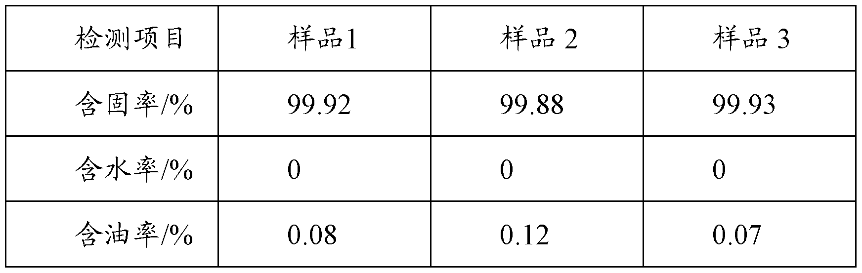
实施例 6 Example 6
釆用实施例 1所述的处理装置进行石油废弃物的工业处理。 将 1000kg钻 井岩屑 (含水率为 19%, 含油率为 7% ) 由进料斗经气锁进入桨叶式干燥机, 利用蒸汽锅炉产生的高温蒸汽 (蒸汽温度为 160 °C , 压力为 0.6MPa, 流量为 120kg/hr)预热物料, 初步除去其中的挥发性组分, 蒸发出的气体由高压风机抽 出, 腔内压力为 -170— 200Pa, 含氧量在 7%左右, 此过程持续 1小时, 物料出 口温度为 92 °C。 The industrial treatment of petroleum waste was carried out using the treatment apparatus described in Example 1. 1000kg drilling cuttings (water content 19%, oil content 7%) are fed into the paddle dryer by air lock from the feed hopper, using high temperature steam generated by steam boiler (steam temperature is 160 °C, pressure is 0.6) MPa, flow rate 120kg / hr) preheating materials, preliminary removal of volatile components, the vaporized gas is extracted by a high-pressure fan, the pressure in the chamber is -170-200Pa, the oxygen content is about 7%, this process continues At 1 hour, the material outlet temperature was 92 °C.
经预热干燥的岩屑通过气锁进入微波加热腔, 到达桨叶输送机的进料端, 这个过程中温度降至 63 °C , 调节中心轴的转速为 1转 /分钟。 两个微波发生器 共输出 llOkw的微波, 通过导波器件传输到微波加热腔内, 对物料进行加热, 使其含有的水和烃类蒸发、 脱离物料, 并及时被高压风机抽出腔体外, 腔体内 压力为 -170— 200Pa, 含氧量在 7%左右, 此过程持续 60分钟, 物料出口温度 为 222 °C。 完成热解吸附的固相残渣被输送到加热腔的出料端时, 通过气锁到 达下游的出料螺旋, 逐渐进行排料, 最终物料落进卸料仓中, 进行储运。 The preheated and dried cuttings enter the microwave heating chamber through the air lock and reach the feeding end of the blade conveyor. During this process, the temperature drops to 63 °C, and the speed of the central shaft is adjusted to 1 rpm. The two microwave generators output a total of llOkw microwaves, which are transmitted to the microwave heating chamber through the waveguide device to heat the materials. The water and hydrocarbons contained therein are evaporated and separated from the material, and are taken out of the chamber by a high-pressure blower in time. The pressure in the chamber is -170-200Pa, and the oxygen content is about 7%. The process lasts for 60 minutes and the material outlet temperature is 222. °C. When the solid phase residue that completes the thermal desorption is transported to the discharge end of the heating chamber, it passes through the air lock to reach the downstream discharge spiral, and gradually discharges, and finally the material falls into the discharge bin for storage and transportation.
该过程中使用锅炉尾气 (主要成分为二氧化碳)充入干燥机和微波加热腔, 以控制其含氧量。 干燥和热解吸附过程中产生的气体由高压风机抽出,经除尘器除去其中的 灰尘,再由一个冷凝器对其进行冷凝,得到的液相油水混合物流进重力沉降器 和油水分离器, 分离回收油和水, 不凝气体经过 UV高效气体净化器处理, 排 放到大气中。 将上述过程得到的固相残渣选取 3个样品点分别进行取样检测,结果如下 (质量百分数): In the process, boiler exhaust gas (mainly carbon dioxide) is used to charge the dryer and microwave heating chamber to control its oxygen content. The gas generated during the drying and thermal desorption process is extracted by a high-pressure fan, and the dust is removed by a dust remover, and then condensed by a condenser, and the obtained liquid-phase oil-water mixture flows into the gravity settler and the oil-water separator, and is separated. The oil and water are recovered, and the non-condensable gas is treated by a UV-efficient gas purifier and discharged to the atmosphere. The solid phase residue obtained in the above process was selected and sampled by three sample points, and the results were as follows (mass percentage):

实施例 7 釆用实施例 1所述的处理装置进行石油废弃物的工业处理。 将 1000kg钻井岩屑 (含水率为 17%, 含油率为 7% ) 由进料斗经气锁进 入桨叶式干燥机, 利用蒸汽锅炉产生的高温蒸汽 (蒸汽温度为 160 °C , 压力为 0.6MPa, 流量为 120kg/hr)预热物料, 初步除去其中的挥发性组分, 蒸发出的 气体由高压风机抽出, 腔内压力为 -170— 200Pa, 含氧量在 7%左右, 此过程持 续 1小时, 物料出口温度为 90°C。 经预热干燥的岩屑通过气锁进入微波加热腔, 到达桨叶输送机的进料端, 这个过程中温度降至 62 °C , 调节中心轴的转速为 1转 /分钟。 两个微波发生器 共输出 120kw的微波, 通过导波器件传输到微波加热腔内, 对物料进行加热, 使其含有的水和烃类蒸发、 脱离物料, 并及时被高压风机抽出腔体外, 腔体内 压力为 -170— 200Pa, 含氧量在 7%左右, 此过程持续 60分钟, 物料出口温度 为 245 °C。 完成热解吸附的固相残渣被输送到加热腔的出料端时, 通过气锁到 达下游的出料螺旋, 逐渐进行排料, 最终物料落进卸料仓中, 进行储运。 该过程中使用锅炉尾气 (主要成分为二氧化碳)充入干燥机和微波加热腔, 以控制其含氧量。 干燥和热解吸附过程中产生的气体由高压风机抽出,经除尘器除去其中的 灰尘,再由一个冷凝器对其进行冷凝,得到的液相油水混合物流进重力沉降器 和油水分离器, 分离回收油和水, 不凝气体经过 UV高效气体净化器处理, 排 放到大气中。 将上述过程得到的固相残渣选取 3个样品点分别进行取样检测,结果如下 (质量百分数): Example 7 The industrial treatment of petroleum waste was carried out using the treatment apparatus described in Example 1. 1000kg drilling cuttings (water content 17%, oil content 7%) are fed into the paddle dryer by gas lock from the feed hopper, using high temperature steam generated by steam boiler (steam temperature is 160 °C, pressure is 0.6) MPa, flow rate 120kg / hr) preheating materials, preliminary removal of volatile components, the vaporized gas is extracted by a high-pressure fan, the pressure in the chamber is -170-200Pa, the oxygen content is about 7%, this process continues At 1 hour, the material outlet temperature was 90 °C. The preheated and dried cuttings enter the microwave heating chamber through the air lock and reach the feeding end of the blade conveyor. During this process, the temperature drops to 62 °C, and the speed of the central axis is adjusted to 1 rpm. The two microwave generators output a total of 120kw of microwaves, which are transmitted to the microwave heating chamber through the waveguide device, and heat the materials to evaporate and remove the water and hydrocarbons, and are quickly extracted by the high-pressure fan. The internal pressure is -170-200Pa, and the oxygen content is about 7%. The process lasts for 60 minutes and the material outlet temperature is 245 °C. When the solid phase residue that completes the thermal desorption is transported to the discharge end of the heating chamber, it passes through the air lock to reach the downstream discharge spiral, and gradually discharges, and finally the material falls into the discharge bin for storage and transportation. In the process, boiler exhaust gas (mainly carbon dioxide) is used to charge the dryer and the microwave heating chamber to control its oxygen content. The gas generated during the drying and thermal desorption process is extracted by a high-pressure fan, and the dust is removed by a dust remover, and then condensed by a condenser, and the obtained liquid-phase oil-water mixture flows into the gravity settler and the oil-water separator, and is separated. The oil and water are recovered, and the non-condensable gas is treated by a UV-efficient gas purifier and discharged to the atmosphere. The solid phase residue obtained in the above process was sampled and tested by three sample points, and the results were as follows (mass percentage):
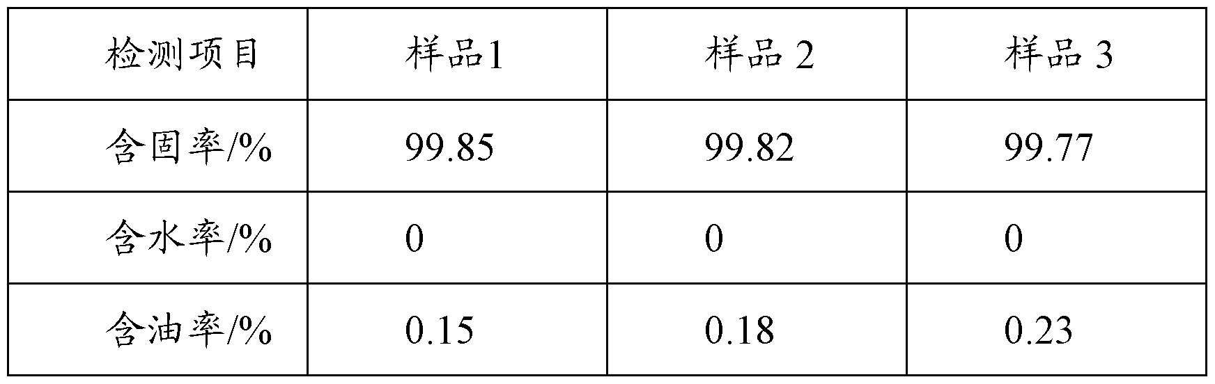
以上实施例的说明仅用于帮助理解本发明的方法及其核心思想。 应当指 出, 对于本技术领域的普通技术人员来说, 在不脱离本发明原理的前提下, 还 可以对本发明进行若干改进和修饰,这些改进和修饰也落入本发明权利要求的 保护范围内。 The above description of the embodiments is only to assist in understanding the method of the present invention and its core idea. It should be noted that those skilled in the art can make several modifications and changes to the present invention without departing from the principles of the present invention. These modifications and modifications also fall within the scope of the present invention. Within the scope of protection.
对所公开的实施例的上述说明,使本领域专业技术人员能够实现或使用本 发明。 对这些实施例的多种修改对本领域的专业技术人员来说将是显而易见 的, 本文中所定义的一般原理可以在不脱离本发明的精神或范围的情况下,在 其它实施例中实现。 因此, 本发明将不会被限制于本文所示的这些实施例, 而 是要符合与本文所公开的原理和新颖特点相一致的最宽的范围。 The above description of the disclosed embodiments enables those skilled in the art to make or use the invention. Various modifications to these embodiments are obvious to those skilled in the art, and the general principles defined herein may be implemented in other embodiments without departing from the spirit or scope of the invention. Therefore, the present invention is not to be limited to the embodiments shown herein, but is to be accorded to the broadest scope of the principles and novel features disclosed herein.
Claims
Applications Claiming Priority (2)
| Application Number | Priority Date | Filing Date | Title |
|---|---|---|---|
| CN201410155734.7 | 2014-04-17 | ||
| CN201410155734.7A CN103923670B (en) | 2014-04-17 | 2014-04-17 | The industrial processing method of oil field waste and device thereof |
Publications (1)
| Publication Number | Publication Date |
|---|---|
| WO2015158016A1 true WO2015158016A1 (en) | 2015-10-22 |
Family
ID=51142072
Family Applications (1)
| Application Number | Title | Priority Date | Filing Date |
|---|---|---|---|
| PCT/CN2014/076479 Ceased WO2015158016A1 (en) | 2014-04-17 | 2014-04-29 | Industrial treatment method and device for oil field wastes |
Country Status (2)
| Country | Link |
|---|---|
| CN (1) | CN103923670B (en) |
| WO (1) | WO2015158016A1 (en) |
Cited By (2)
| Publication number | Priority date | Publication date | Assignee | Title |
|---|---|---|---|---|
| CN106338066A (en) * | 2016-03-14 | 2017-01-18 | 四川宏图普新微波科技有限公司 | Solid organic material cracking method and system |
| CN109653716A (en) * | 2018-10-29 | 2019-04-19 | 中国石油天然气集团有限公司 | Super-viscous oil is handled up development block closed gathering method and device |
Families Citing this family (54)
| Publication number | Priority date | Publication date | Assignee | Title |
|---|---|---|---|---|
| CZ304835B6 (en) * | 2013-09-04 | 2014-11-26 | Hedviga Group, A.S. | Process for producing fuels for power engineering and fuel producing apparatus |
| CN104150728B (en) * | 2014-08-01 | 2016-01-20 | 杰瑞能源服务有限公司 | A kind of oilfield waste substance treating method and system |
| CN104178200B (en) * | 2014-08-14 | 2016-05-04 | 中国石油集团川庆钻探工程有限公司工程技术研究院 | The hot analyzing and processing method of a kind of oil base drilling cuttings |
| CN105201432A (en) * | 2015-10-08 | 2015-12-30 | 中国石油天然气股份有限公司 | A method for treating oily drilling cuttings |
| CN105945041A (en) * | 2016-06-29 | 2016-09-21 | 程秀 | Thermal desorption treatment method for tar residues |
| CN106082580A (en) * | 2016-08-12 | 2016-11-09 | 东华大学 | A kind of greasy filth is dried and the close-coupled processing Zero emission device of carbonization |
| DE102017102271B4 (en) | 2017-02-06 | 2021-08-12 | Rheinmetall Waffe Munition Gmbh | Method and device for drying explosives |
| US11624326B2 (en) | 2017-05-21 | 2023-04-11 | Bj Energy Solutions, Llc | Methods and systems for supplying fuel to gas turbine engines |
| CN107120078A (en) * | 2017-06-07 | 2017-09-01 | 西南石油大学 | Oil-contained drilling cuttings microwave thermal desorption apparatus for continuous treatment |
| CN107282607B (en) * | 2017-08-15 | 2024-09-20 | 上海艾目介流体技术有限公司 | Oil-containing solid waste microwave thermal desorption recycling treatment system and treatment method |
| CN111378513B (en) * | 2018-12-28 | 2021-04-06 | 中国石油化工股份有限公司 | Auxiliary agent for biomass treatment and biomass gasification treatment method |
| TWI705862B (en) | 2019-01-31 | 2020-10-01 | 廖珮瑜 | Continuous treatment method and system for sludge or waste |
| US11560845B2 (en) | 2019-05-15 | 2023-01-24 | Bj Energy Solutions, Llc | Mobile gas turbine inlet air conditioning system and associated methods |
| CN110259399B (en) * | 2019-06-25 | 2024-02-06 | 成都华寰环保科技有限公司 | A technology and device for recovering base oil in drilling oil-based mud cuttings |
| CN110500055B (en) * | 2019-08-27 | 2024-07-02 | 河北迪运化工科技有限公司 | Separation recovery unit of oil-containing mixture in petroleum drilling and oil recovery process |
| US11015594B2 (en) | 2019-09-13 | 2021-05-25 | Bj Energy Solutions, Llc | Systems and method for use of single mass flywheel alongside torsional vibration damper assembly for single acting reciprocating pump |
| US10989180B2 (en) | 2019-09-13 | 2021-04-27 | Bj Energy Solutions, Llc | Power sources and transmission networks for auxiliary equipment onboard hydraulic fracturing units and associated methods |
| CA3092859A1 (en) | 2019-09-13 | 2021-03-13 | Bj Energy Solutions, Llc | Fuel, communications, and power connection systems and related methods |
| US12065968B2 (en) | 2019-09-13 | 2024-08-20 | BJ Energy Solutions, Inc. | Systems and methods for hydraulic fracturing |
| CA3092865C (en) | 2019-09-13 | 2023-07-04 | Bj Energy Solutions, Llc | Power sources and transmission networks for auxiliary equipment onboard hydraulic fracturing units and associated methods |
| US11555756B2 (en) | 2019-09-13 | 2023-01-17 | Bj Energy Solutions, Llc | Fuel, communications, and power connection systems and related methods |
| US11015536B2 (en) | 2019-09-13 | 2021-05-25 | Bj Energy Solutions, Llc | Methods and systems for supplying fuel to gas turbine engines |
| US10815764B1 (en) | 2019-09-13 | 2020-10-27 | Bj Energy Solutions, Llc | Methods and systems for operating a fleet of pumps |
| US12338772B2 (en) | 2019-09-13 | 2025-06-24 | Bj Energy Solutions, Llc | Systems, assemblies, and methods to enhance intake air flow to a gas turbine engine of a hydraulic fracturing unit |
| CA3092863C (en) | 2019-09-13 | 2023-07-18 | Bj Energy Solutions, Llc | Fuel, communications, and power connection systems and related methods |
| US11002189B2 (en) | 2019-09-13 | 2021-05-11 | Bj Energy Solutions, Llc | Mobile gas turbine inlet air conditioning system and associated methods |
| CA3191280A1 (en) | 2019-09-13 | 2021-03-13 | Bj Energy Solutions, Llc | Methods and systems for supplying fuel to gas turbine engines |
| US10895202B1 (en) | 2019-09-13 | 2021-01-19 | Bj Energy Solutions, Llc | Direct drive unit removal system and associated methods |
| US11708829B2 (en) | 2020-05-12 | 2023-07-25 | Bj Energy Solutions, Llc | Cover for fluid systems and related methods |
| US10968837B1 (en) | 2020-05-14 | 2021-04-06 | Bj Energy Solutions, Llc | Systems and methods utilizing turbine compressor discharge for hydrostatic manifold purge |
| US11428165B2 (en) | 2020-05-15 | 2022-08-30 | Bj Energy Solutions, Llc | Onboard heater of auxiliary systems using exhaust gases and associated methods |
| US11208880B2 (en) | 2020-05-28 | 2021-12-28 | Bj Energy Solutions, Llc | Bi-fuel reciprocating engine to power direct drive turbine fracturing pumps onboard auxiliary systems and related methods |
| US11109508B1 (en) | 2020-06-05 | 2021-08-31 | Bj Energy Solutions, Llc | Enclosure assembly for enhanced cooling of direct drive unit and related methods |
| US10961908B1 (en) | 2020-06-05 | 2021-03-30 | Bj Energy Solutions, Llc | Systems and methods to enhance intake air flow to a gas turbine engine of a hydraulic fracturing unit |
| US11208953B1 (en) | 2020-06-05 | 2021-12-28 | Bj Energy Solutions, Llc | Systems and methods to enhance intake air flow to a gas turbine engine of a hydraulic fracturing unit |
| US10954770B1 (en) | 2020-06-09 | 2021-03-23 | Bj Energy Solutions, Llc | Systems and methods for exchanging fracturing components of a hydraulic fracturing unit |
| US11022526B1 (en) | 2020-06-09 | 2021-06-01 | Bj Energy Solutions, Llc | Systems and methods for monitoring a condition of a fracturing component section of a hydraulic fracturing unit |
| US11066915B1 (en) | 2020-06-09 | 2021-07-20 | Bj Energy Solutions, Llc | Methods for detection and mitigation of well screen out |
| US11933153B2 (en) | 2020-06-22 | 2024-03-19 | Bj Energy Solutions, Llc | Systems and methods to operate hydraulic fracturing units using automatic flow rate and/or pressure control |
| US11125066B1 (en) | 2020-06-22 | 2021-09-21 | Bj Energy Solutions, Llc | Systems and methods to operate a dual-shaft gas turbine engine for hydraulic fracturing |
| US11939853B2 (en) | 2020-06-22 | 2024-03-26 | Bj Energy Solutions, Llc | Systems and methods providing a configurable staged rate increase function to operate hydraulic fracturing units |
| US11028677B1 (en) | 2020-06-22 | 2021-06-08 | Bj Energy Solutions, Llc | Stage profiles for operations of hydraulic systems and associated methods |
| US11473413B2 (en) | 2020-06-23 | 2022-10-18 | Bj Energy Solutions, Llc | Systems and methods to autonomously operate hydraulic fracturing units |
| US11466680B2 (en) | 2020-06-23 | 2022-10-11 | Bj Energy Solutions, Llc | Systems and methods of utilization of a hydraulic fracturing unit profile to operate hydraulic fracturing units |
| US11149533B1 (en) | 2020-06-24 | 2021-10-19 | Bj Energy Solutions, Llc | Systems to monitor, detect, and/or intervene relative to cavitation and pulsation events during a hydraulic fracturing operation |
| US11220895B1 (en) | 2020-06-24 | 2022-01-11 | Bj Energy Solutions, Llc | Automated diagnostics of electronic instrumentation in a system for fracturing a well and associated methods |
| CN111701985A (en) * | 2020-06-27 | 2020-09-25 | 商洛市海蓝科技有限公司 | Oil field solid waste microwave degradation processing unit |
| CN111701984A (en) * | 2020-06-27 | 2020-09-25 | 商洛市海蓝科技有限公司 | Oil field solid waste microwave degradation processing apparatus |
| US11193361B1 (en) | 2020-07-17 | 2021-12-07 | Bj Energy Solutions, Llc | Methods, systems, and devices to enhance fracturing fluid delivery to subsurface formations during high-pressure fracturing operations |
| CN112645563A (en) * | 2020-12-25 | 2021-04-13 | 苏州精英环保有限公司 | Combined type ex-situ thermal desorption treatment system for oil sludge |
| US11639654B2 (en) | 2021-05-24 | 2023-05-02 | Bj Energy Solutions, Llc | Hydraulic fracturing pumps to enhance flow of fracturing fluid into wellheads and related methods |
| US12378864B2 (en) | 2021-10-25 | 2025-08-05 | Bj Energy Solutions, Llc | Systems and methods to reduce acoustic resonance or disrupt standing wave formation in a fluid manifold of a high-pressure fracturing system |
| CN114100546A (en) * | 2021-12-07 | 2022-03-01 | 苏州汉浩分离技术有限公司 | Device and method for separating natural products |
| CN114482927B (en) * | 2021-12-31 | 2024-06-07 | 西安本清化学技术有限公司 | A green and low-carbon development system and method for heavy oil |
Citations (4)
| Publication number | Priority date | Publication date | Assignee | Title |
|---|---|---|---|---|
| CN101963358A (en) * | 2010-09-30 | 2011-02-02 | 昆明理工大学 | Combined treatment method for oilfield solid waste |
| US20110132902A1 (en) * | 2009-12-07 | 2011-06-09 | Novak John F | Method and apparatus for microwave-based liquid vaporization system |
| CN202529962U (en) * | 2012-03-09 | 2012-11-14 | 中国石油天然气股份有限公司 | Continuous feeding type oil sludge microwave heat treatment device |
| CN103058481A (en) * | 2011-10-21 | 2013-04-24 | 中国石油化工股份有限公司 | A method for microwave catalytic pyrolysis treatment of oil sludge |
Family Cites Families (8)
| Publication number | Priority date | Publication date | Assignee | Title |
|---|---|---|---|---|
| CN101560404A (en) * | 2008-04-15 | 2009-10-21 | 上海鸿泽企业发展有限公司 | Method for preparing biomass oil in microwave thermal decomposition way |
| CN102071041A (en) * | 2011-01-30 | 2011-05-25 | 福州大学 | Method for preparing bio-oil by continuously and rapidly cracking mushroom wastes |
| CN102874997A (en) * | 2011-07-11 | 2013-01-16 | 中国石油化工股份有限公司 | Oil-containing sludge pyrolysis and its resource treatment method |
| CN102849905B (en) * | 2012-03-22 | 2014-01-15 | 中国石油天然气股份有限公司 | Experimental method for heat treatment of oily sludge |
| CN103160301B (en) * | 2013-03-21 | 2014-04-16 | 何建祥 | Low-temperature carbonization apparatus and method for oil sand, oil sludge, oil shale and biomass |
| CN103420555B (en) * | 2013-08-01 | 2015-07-15 | 中国大唐集团科学技术研究院有限公司 | Oil sludge treating system and method |
| CN103449701B (en) * | 2013-08-14 | 2015-04-08 | 湖州宜可欧环保科技有限公司 | Method and device for refinery sludge carbonization treatment and carbon recovery |
| CN203890292U (en) * | 2014-04-17 | 2014-10-22 | 杰瑞能源服务有限公司 | Oilfield waste industrial treatment device co |
-
2014
- 2014-04-17 CN CN201410155734.7A patent/CN103923670B/en active Active
- 2014-04-29 WO PCT/CN2014/076479 patent/WO2015158016A1/en not_active Ceased
Patent Citations (4)
| Publication number | Priority date | Publication date | Assignee | Title |
|---|---|---|---|---|
| US20110132902A1 (en) * | 2009-12-07 | 2011-06-09 | Novak John F | Method and apparatus for microwave-based liquid vaporization system |
| CN101963358A (en) * | 2010-09-30 | 2011-02-02 | 昆明理工大学 | Combined treatment method for oilfield solid waste |
| CN103058481A (en) * | 2011-10-21 | 2013-04-24 | 中国石油化工股份有限公司 | A method for microwave catalytic pyrolysis treatment of oil sludge |
| CN202529962U (en) * | 2012-03-09 | 2012-11-14 | 中国石油天然气股份有限公司 | Continuous feeding type oil sludge microwave heat treatment device |
Cited By (4)
| Publication number | Priority date | Publication date | Assignee | Title |
|---|---|---|---|---|
| CN106338066A (en) * | 2016-03-14 | 2017-01-18 | 四川宏图普新微波科技有限公司 | Solid organic material cracking method and system |
| CN106338066B (en) * | 2016-03-14 | 2018-12-07 | 四川宏图普新微波科技有限公司 | A kind of cleavage method and system of solid organic material |
| CN109653716A (en) * | 2018-10-29 | 2019-04-19 | 中国石油天然气集团有限公司 | Super-viscous oil is handled up development block closed gathering method and device |
| CN109653716B (en) * | 2018-10-29 | 2021-10-08 | 中国石油天然气集团有限公司 | Ultra-thick oil huff and puff development block closed gathering and transportation method and device |
Also Published As
| Publication number | Publication date |
|---|---|
| CN103923670B (en) | 2016-04-20 |
| CN103923670A (en) | 2014-07-16 |
Similar Documents
| Publication | Publication Date | Title |
|---|---|---|
| WO2015158016A1 (en) | Industrial treatment method and device for oil field wastes | |
| CN203890292U (en) | Oilfield waste industrial treatment device co | |
| CN207391231U (en) | A kind of refinery's oily sludge high-temperature steam pyrolysis installation | |
| CN107200452B (en) | Device and method for microwave pyrolysis of sludge | |
| CN107117787B (en) | A process method for synergistic pyrolysis of oily sludge by adding microalgae biomass | |
| CN108101335A (en) | A kind of oily sludge continuous processing technique and processing unit | |
| CN108911456B (en) | Novel oily sludge treatment method and system | |
| CN108840539B (en) | Oil sludge and sludge cooperative treatment device and method | |
| CN209276447U (en) | A continuous pyrolysis and carbonization system for high-viscosity liquid organic waste | |
| CN109990301B (en) | Negative pressure reverse burning equipment for oil pollutants and oil recovery method | |
| WO2019050431A1 (en) | Method for utilizing solid carbon-containing waste by pyrolysis and waste processing complex for implementing same | |
| CN104876421A (en) | Treatment method of oilfield waste and device thereof | |
| CN104860508A (en) | Oil field waste treatment method and device | |
| CN110330198B (en) | Oil sludge treatment method and system | |
| CN106807734B (en) | Thermal desorption system for organic contaminated soil | |
| US8298304B1 (en) | Coal treatment process for a coal-fired power plant | |
| CN104692607B (en) | A kind of greasy filth pyrolysis resource utilization method and device | |
| WO2013015719A1 (en) | Method for processing solid waste and apparatus for carrying out said method | |
| KR101296267B1 (en) | Recycling apparatus for waste wire | |
| RU2543619C1 (en) | Device for processing rubber wastes | |
| CN203360242U (en) | Oil sludge treatment system | |
| CN108246774A (en) | A kind of organic pollution environmental protection pyrolysis treatment systems and method | |
| CN204529626U (en) | A kind of greasy filth pyrolysis resource utilization device | |
| CN107513392A (en) | It is a kind of to handle house refuse and the system and method for sewage sludge | |
| CN109442437B (en) | Incineration treatment system and method for low-concentration organic waste liquid |
Legal Events
| Date | Code | Title | Description |
|---|---|---|---|
| 121 | Ep: the epo has been informed by wipo that ep was designated in this application |
Ref document number: 14889372 Country of ref document: EP Kind code of ref document: A1 |
|
| NENP | Non-entry into the national phase |
Ref country code: DE |
|
| 122 | Ep: pct application non-entry in european phase |
Ref document number: 14889372 Country of ref document: EP Kind code of ref document: A1 |