WO2015119028A1 - 変速機の油圧回路 - Google Patents
変速機の油圧回路 Download PDFInfo
- Publication number
- WO2015119028A1 WO2015119028A1 PCT/JP2015/052452 JP2015052452W WO2015119028A1 WO 2015119028 A1 WO2015119028 A1 WO 2015119028A1 JP 2015052452 W JP2015052452 W JP 2015052452W WO 2015119028 A1 WO2015119028 A1 WO 2015119028A1
- Authority
- WO
- WIPO (PCT)
- Prior art keywords
- port
- oil
- pump
- pressure
- main pump
- Prior art date
- Legal status (The legal status is an assumption and is not a legal conclusion. Google has not performed a legal analysis and makes no representation as to the accuracy of the status listed.)
- Ceased
Links
Images




Classifications
-
- F—MECHANICAL ENGINEERING; LIGHTING; HEATING; WEAPONS; BLASTING
- F16—ENGINEERING ELEMENTS AND UNITS; GENERAL MEASURES FOR PRODUCING AND MAINTAINING EFFECTIVE FUNCTIONING OF MACHINES OR INSTALLATIONS; THERMAL INSULATION IN GENERAL
- F16H—GEARING
- F16H61/00—Control functions within control units of change-speed- or reversing-gearings for conveying rotary motion ; Control of exclusively fluid gearing, friction gearing, gearings with endless flexible members or other particular types of gearing
- F16H61/0021—Generation or control of line pressure
-
- F—MECHANICAL ENGINEERING; LIGHTING; HEATING; WEAPONS; BLASTING
- F16—ENGINEERING ELEMENTS AND UNITS; GENERAL MEASURES FOR PRODUCING AND MAINTAINING EFFECTIVE FUNCTIONING OF MACHINES OR INSTALLATIONS; THERMAL INSULATION IN GENERAL
- F16H—GEARING
- F16H57/00—General details of gearing
- F16H57/04—Features relating to lubrication or cooling or heating
- F16H57/0434—Features relating to lubrication or cooling or heating relating to lubrication supply, e.g. pumps; Pressure control
- F16H57/0436—Pumps
-
- F—MECHANICAL ENGINEERING; LIGHTING; HEATING; WEAPONS; BLASTING
- F16—ENGINEERING ELEMENTS AND UNITS; GENERAL MEASURES FOR PRODUCING AND MAINTAINING EFFECTIVE FUNCTIONING OF MACHINES OR INSTALLATIONS; THERMAL INSULATION IN GENERAL
- F16H—GEARING
- F16H57/00—General details of gearing
- F16H57/04—Features relating to lubrication or cooling or heating
- F16H57/0434—Features relating to lubrication or cooling or heating relating to lubrication supply, e.g. pumps; Pressure control
- F16H57/0446—Features relating to lubrication or cooling or heating relating to lubrication supply, e.g. pumps; Pressure control the supply forming part of the transmission control unit, e.g. for automatic transmissions
-
- F—MECHANICAL ENGINEERING; LIGHTING; HEATING; WEAPONS; BLASTING
- F16—ENGINEERING ELEMENTS AND UNITS; GENERAL MEASURES FOR PRODUCING AND MAINTAINING EFFECTIVE FUNCTIONING OF MACHINES OR INSTALLATIONS; THERMAL INSULATION IN GENERAL
- F16H—GEARING
- F16H61/00—Control functions within control units of change-speed- or reversing-gearings for conveying rotary motion ; Control of exclusively fluid gearing, friction gearing, gearings with endless flexible members or other particular types of gearing
- F16H61/0021—Generation or control of line pressure
- F16H61/0025—Supply of control fluid; Pumps therefor
-
- F—MECHANICAL ENGINEERING; LIGHTING; HEATING; WEAPONS; BLASTING
- F16—ENGINEERING ELEMENTS AND UNITS; GENERAL MEASURES FOR PRODUCING AND MAINTAINING EFFECTIVE FUNCTIONING OF MACHINES OR INSTALLATIONS; THERMAL INSULATION IN GENERAL
- F16H—GEARING
- F16H61/00—Control functions within control units of change-speed- or reversing-gearings for conveying rotary motion ; Control of exclusively fluid gearing, friction gearing, gearings with endless flexible members or other particular types of gearing
- F16H61/0021—Generation or control of line pressure
- F16H61/0025—Supply of control fluid; Pumps therefor
- F16H61/0031—Supply of control fluid; Pumps therefor using auxiliary pumps, e.g. pump driven by a different power source than the engine
-
- F—MECHANICAL ENGINEERING; LIGHTING; HEATING; WEAPONS; BLASTING
- F16—ENGINEERING ELEMENTS AND UNITS; GENERAL MEASURES FOR PRODUCING AND MAINTAINING EFFECTIVE FUNCTIONING OF MACHINES OR INSTALLATIONS; THERMAL INSULATION IN GENERAL
- F16H—GEARING
- F16H61/00—Control functions within control units of change-speed- or reversing-gearings for conveying rotary motion ; Control of exclusively fluid gearing, friction gearing, gearings with endless flexible members or other particular types of gearing
- F16H61/02—Control functions within control units of change-speed- or reversing-gearings for conveying rotary motion ; Control of exclusively fluid gearing, friction gearing, gearings with endless flexible members or other particular types of gearing characterised by the signals used
- F16H61/0202—Control functions within control units of change-speed- or reversing-gearings for conveying rotary motion ; Control of exclusively fluid gearing, friction gearing, gearings with endless flexible members or other particular types of gearing characterised by the signals used the signals being electric
- F16H61/0204—Control functions within control units of change-speed- or reversing-gearings for conveying rotary motion ; Control of exclusively fluid gearing, friction gearing, gearings with endless flexible members or other particular types of gearing characterised by the signals used the signals being electric for gearshift control, e.g. control functions for performing shifting or generation of shift signal
- F16H61/0206—Layout of electro-hydraulic control circuits, e.g. arrangement of valves
-
- F—MECHANICAL ENGINEERING; LIGHTING; HEATING; WEAPONS; BLASTING
- F16—ENGINEERING ELEMENTS AND UNITS; GENERAL MEASURES FOR PRODUCING AND MAINTAINING EFFECTIVE FUNCTIONING OF MACHINES OR INSTALLATIONS; THERMAL INSULATION IN GENERAL
- F16H—GEARING
- F16H61/00—Control functions within control units of change-speed- or reversing-gearings for conveying rotary motion ; Control of exclusively fluid gearing, friction gearing, gearings with endless flexible members or other particular types of gearing
- F16H61/0021—Generation or control of line pressure
- F16H2061/0037—Generation or control of line pressure characterised by controlled fluid supply to lubrication circuits of the gearing
Definitions
- the present invention provides a transmission including a main pump and a sub pump driven by a common drive source, supplying oil discharged from the main pump to a shift control system and supplying oil discharged from the sub pump to a lubrication system. It relates to a hydraulic circuit.
- Japanese Patent Application Laid-Open Publication No. 2004-228667 discloses that when a hydraulic pressure of a torque converter or a lubrication system is lowered, a supply destination of oil discharged from a sub pump is switched in the order of a pulley oil chamber, a torque converter, and a lubrication system.
- the oil discharged from the oil pump when the engine is started is first used for filling the pulley oil chamber and then used for filling the torque converter, which may delay the start of the vehicle. .
- the present invention has been made in view of the above-described circumstances, and an object thereof is to quickly fill oil in a torque converter in a hydraulic circuit of a transmission including a main pump and a sub pump.
- a main pump and a sub pump driven by a common drive source are provided, and oil discharged from the main pump is supplied to a shift control system, and the sub pump discharges the oil.
- a hydraulic circuit of a transmission for supplying oil to a lubrication system, wherein a switching valve for assisting the main pump by increasing the discharge pressure of the sub pump when the discharge flow rate of the main pump is insufficient, and the main pump A first pressure regulating valve for regulating the hydraulic pressure supplied to the speed change control system; a first oil passage connecting the discharge port of the main pump and the first port of the first pressure regulating valve; and a discharge port of the sub pump.
- a second oil passage connecting the first port of the switching valve and the discharge port of the main pump and the discharge port of the sub pump.
- a third oil passage, a one-way valve interposed in the third oil passage and opened when a discharge pressure of the sub pump is higher than a discharge pressure of the main pump, and a torque converter from the main pump or the sub pump A second pressure regulating valve that regulates the hydraulic pressure supplied to the first valve, a fourth oil passage connecting the first port of the switching valve and the first port of the second pressure regulating valve, and a first pressure regulating valve of the first pressure regulating valve.
- a hydraulic circuit for a transmission having the first feature is proposed.
- the second pressure regulating valve includes a feedback port connected to the second port, and when the internal pressure of the torque converter exceeds a predetermined value, the second pressure regulating valve is provided.
- a hydraulic circuit for a transmission is proposed in which the communication between the first port and the second port of the pressure valve is blocked and the first port and the second port of the switching valve are in communication.
- the first pressure regulating valve includes a feedback port connected to the first port, and when the internal pressure of the torque converter becomes a predetermined value or less, A hydraulic circuit for a transmission is proposed in which the communication between the first port and the second port of the switching valve is blocked.
- a fourth feature is provided with a solenoid valve for operating the switching valve to a position where communication between the first port and the second port is blocked.
- a transmission hydraulic circuit is proposed.
- a fifth feature is that the sub pump has a lower discharge pressure and a higher discharge flow rate than the main pump.
- a hydraulic circuit for a transmission is proposed.
- the engine E of the embodiment corresponds to the drive source of the present invention
- the pulley oil chambers 27a and 28a of the embodiment correspond to the shift control system of the present invention.
- the hydraulic circuit of the transmission includes a main pump and a sub pump driven by a common drive source, supplies oil discharged from the main pump to the shift control system, and discharges the sub pump. Supply oil to the lubrication system.
- the discharge flow rate of the main pump is insufficient, the discharge pressure of the sub pump is increased by the switching valve to assist the main pump. Therefore, the main pump can be reduced in size and the driving load can be reduced.
- the oil discharged from the main pump is supplied through the first oil passage ⁇ the first port of the first pressure regulating valve ⁇ the passage of the speed change control system to be used for the speed change control of the transmission, and the oil discharged from the sub pump.
- the one-way valve of the third oil passage is closed and the second oil passage is closed. The communication between the first oil passage and the second oil passage is blocked.
- the internal pressure of the torque converter is low, so that sufficient hydraulic pressure is not transmitted to the feedback port of the switching valve via the fifth oil passage. Since the communication between the first port and the second port is cut off, the oil discharged from the sub pump is not supplied to the lubrication system, and the second oil passage ⁇ the first port of the switching valve ⁇ the fourth oil passage ⁇ the second oil passage.
- the two pressure regulating valves are supplied via the first port and the second port ⁇ the torque converter, and the inside of the torque converter can be quickly filled with oil to enable transmission of driving force.
- the second pressure regulating valve includes a feedback port connected to the second port, and when the internal pressure of the torque converter exceeds a predetermined value, the first port of the second pressure regulating valve and Since the communication of the second port is cut off and the first port and the second port of the switching valve are connected, the oil discharged from the sub pump is supplied only to the lubrication system, and the driving load of the sub pump is reduced. Can do.
- the first pressure regulating valve since the first pressure regulating valve includes a feedback port connected to the first port, if the hydraulic pressure of the speed change control system is insufficient due to a sudden shift, the first pressure regulating valve The communication between the port and the second port is cut off, and the hydraulic pressure is not supplied to the torque converter. As a result, when the internal pressure of the torque converter falls below a predetermined value, the communication between the first port and the second port of the switching valve is shut off, so that all the oil discharged from the sub-pump is supplied to the shift control system side and a quick shift is performed. As a result, the shift response at the time of sudden shift is ensured.
- the solenoid valve for operating the switching valve to a position where the communication between the first port and the second port is blocked is provided.
- the sub-pump mainly responsible for lubrication has a low discharge pressure and a large discharge flow rate
- the main pump mainly responsible for gear shifting has a high discharge pressure and a small discharge flow rate.
- the total driving load of the source can be reduced.
- FIG. 1 is a longitudinal sectional view of a belt type continuously variable transmission.
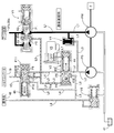
- FIG. 2 is a hydraulic circuit diagram of the belt type continuously variable transmission.
- FIG. 3 is a hydraulic circuit diagram for explaining the operation when starting the engine.
- FIG. 4 is a hydraulic circuit diagram for explaining the operation during normal operation.
- FIG. 5 is a hydraulic circuit diagram for explaining the operation of automatic switching during sudden shift.
- FIG. 6 is a hydraulic circuit diagram for explaining the action of forced switching at the time of sudden shift.
- a transmission case 11 of the belt-type continuously variable transmission T includes a torque converter case 12 coupled to an engine (not shown) and a transmission case body 13 coupled to the torque converter case 12. 11, an input shaft 14, a drive pulley shaft 15, a driven pulley shaft 16, and an idle shaft 17 are supported in parallel.
- a forward drive gear 21 that can be coupled to the input shaft 14 via a forward clutch 20 is rotatably supported on the input shaft 14 connected to the crankshaft 18 of the engine via a torque converter 19.
- the forward drive gear 21 meshes with a forward driven gear 22 fixed to the drive pulley shaft 15.
- a reverse driven gear 24 that can be coupled to the drive pulley shaft 15 via a reverse clutch 23 is supported on the drive pulley shaft 15 so as to be relatively rotatable.
- the reverse driven gear 24 is supported by an idle shaft 17. It meshes with a reverse drive gear 26 fixed to the input shaft 14 via a gear 25.
- a drive pulley 27 supported by the drive pulley shaft 15 and a driven pulley 28 supported by the driven pulley shaft 16 are connected by a metal belt 29, and a pulley oil chamber 27a of the drive pulley 27 and a pulley oil chamber 28a of the driven pulley 28 are connected.
- the ratio between the drive pulley shaft 15 and the driven pulley shaft 16 can be changed by controlling the hydraulic pressure supplied to the drive pulley 27 and changing the groove widths of the drive pulley 27 and the driven pulley 28.
- a final drive gear 30 fixed to the driven pulley shaft 16 is engaged with a final driven gear 32 fixed to the case of the differential gear 31, and the left and right axles 33, 33 are connected to the outside of the transmission case 11 from the differential gear 31. Extend.
- the driving force of the engine is as follows: crankshaft 18 ⁇ torque converter 19 ⁇ input shaft 14 ⁇ forward clutch 20 ⁇ forward drive gear 21 ⁇ Driven gear 22 is driven by a path of forward driven gear 22 ⁇ drive pulley shaft 15 ⁇ drive pulley 27 ⁇ metal belt 29 ⁇ driven pulley 28 ⁇ driven pulley shaft 16 ⁇ final drive gear 30 ⁇ final driven gear 32 ⁇ differential gear 31 ⁇ axles 33 and 33. The vehicle is moved forward.
- the groove width of the drive pulley 27 is decreased to increase the groove width of the driven pulley 28, the ratio between the drive pulley shaft 15 and the driven pulley shaft 16 is stepless. If the vehicle speed is decreased and the groove width of the drive pulley 27 is increased to decrease the groove width of the driven pulley 28, the ratio between the drive pulley shaft 15 and the driven pulley shaft 16 is continuously reduced. The vehicle speed increases.
- the hydraulic circuit includes a main pump PM and a sub pump PS that are driven by an engine E that is a drive source of the belt-type continuously variable transmission T described above.
- the characteristics of the main pump PM used mainly for gear shifting are set such that the discharge pressure is relatively high and the discharge flow rate is set relatively small, and the characteristics of the sub-pump PS used mainly for lubrication are discharge with a relatively low discharge pressure.
- the flow rate is set to be relatively large, whereby the total driving load of the hydraulic power source of the belt type continuously variable transmission T can be reduced.
- the oil pumped up from the oil tank 41 by the main pump PM is supplied to the first oil passage L1, and belt-type continuously variable transmissions such as pulley oil chambers 27a and 28a from the first oil passage L1 through the first pressure regulating valve V1. Supplied to T shift control system.
- the oil pumped up from the oil tank 41 by the sub pump PS is supplied to the second oil passage L2, and is supplied from the second oil passage L2 to the torque converter 19 via the switching valve V2, the fourth oil passage L4, and the second pressure regulating valve V3. While being supplied, it is supplied from the second oil passage L2 to the lubrication system 48 such as each bearing of the belt type continuously variable transmission T through the switching valve V2 and the sixth oil passage L6.
- the first oil passage L1 and the second oil passage L2 are connected via a third oil passage L3, and a one-way valve V4 is disposed in the third oil passage L3.
- the one-way valve V4 blocks the flow of oil from the first oil path L1 to the second oil path L2, and allows the oil to flow from the second oil path L2 to the first oil path L1.
- the first pressure regulating valve V1 includes a spool 43 biased to the left side by a spring 42.
- a groove 43a is formed in the spool 43, and a first port P1 and a second port facing the outer peripheral surface of the spool 43 are formed.
- a port P2 and a feedback port P3 are formed.
- the first port P1 is connected to the first oil passage L1 and the pulley oil chambers 27a and 28a
- the feedback port P3 is connected to the pulley oil chambers 27a and 28a
- the second port P2 is connected to the switching valve V2 via the oil passage L5. It is connected to the feedback port P4 and the second port P9 of the second pressure regulating valve V3.
- the switching valve V2 includes a spool 45 urged to the left side by a spring 44.
- the spool 45 is formed with a groove 45a, and a first port P5, a second port P6 facing the outer peripheral surface of the spool 45, A third port P7 and the feedback port P4 are formed.
- the first port P5 is connected to the second oil passage L2, and is connected to the first port P8 of the second pressure regulating valve V3 via the fourth oil passage L4, and the second port P6 is connected to the sixth oil passage L6.
- the third port P7 is connected to an on / off type solenoid valve V5 via a seventh oil passage L7.
- the second pressure regulating valve V3 includes a spool 47 biased to the right by a spring 46.
- the spool 47 is formed with a groove 47a, and a second port P9 and a third port facing the outer periphery of the spool 47.
- P10, a feedback port P11, and the first port P8 are formed.
- the first port P8 is connected to the fourth oil passage L4, the second port P9 is connected to the fifth oil passage L5 and the torque converter 19, and the third port P10 is connected to the first switch valve V2 via the eighth oil passage L8. It is connected to the 2-port P6, the fifth oil passage L5, and the lubrication system 48.
- the sixth oil passage L6 is connected to the oil tank 41 via a relief valve V6.
- the oil pressure in the pulley oil chambers 27a and 28a has not yet risen, so the first pressure regulating valve V1
- the spool 43 is moved to the left by the elastic force of the spring 42 to block communication between the first port P1 and the second port P2. Therefore, the oil discharged from the main pump PM is supplied through the route of the first oil passage L1 ⁇ the first port P1 of the first pressure regulating valve V1 ⁇ the pulley oil chambers 27a and 28a, and the belt-type continuously variable transmission T is shifted. It becomes possible.
- the oil discharged from the sub pump PS operating together with the main pump PM is the second oil passage L2, the first port P5 of the switching valve V2, the fourth oil passage L4, the first port P8 and the second port P9 of the second pressure regulating valve V3.
- ⁇ Supplied through the route of the torque converter 19.
- the internal pressure is low, and the hydraulic pressure applied to the feedback port P4 of the switching valve V2 is defeated by the elastic force of the spring 44, and the spool 45 moves to the left.
- the communication between the first port P5 and the second port P6 of the switching valve V2 is blocked, and the oil discharged from the sub pump PS is not supplied to the lubrication system 48.
- the one-way valve V4 interposed in the third oil passage L3 connecting the first oil passage L1 and the second oil passage L2 is closed, and the main Oil discharged from the pump PM does not flow to the sub pump PS side.
- the oil pressure in the pulley oil chambers 27a and 28a rises sufficiently, so that the spool 43 is moved rightward to a position where the spool 43 is balanced with the elastic force of the spring 42 by the oil pressure applied to the feedback port P3 of the first pressure regulating valve V1.
- P1 communicates with the second port P2 to exert the pressure regulating function, and after that, the oil remaining when the main pump PM is generated and regulated by the first pressure regulating valve V1 is the fifth oil passage L5.
- Is supplied to the second pressure regulating valve V3, is regulated by the second pressure regulating valve V3, and is supplied to the torque converter 19.
- the oil discharged from the sub pump PS is supplied through the second oil passage L2 ⁇ the first port P5 of the switching valve V2 and the second port P6 ⁇ the sixth oil passage L6 ⁇ the lubrication system 48, and is used only for lubrication. Is done. Therefore, the driving load of the engine E can be reduced by lowering the discharge pressure of the sub pump PS.
- the one-way valve V4 interposed in the third oil passage L3 connecting the first oil passage L1 and the second oil passage L2 is closed. However, the oil discharged from the main pump PM does not flow to the sub pump PS side.
- the switching of the switching valve V2 described with reference to FIG. 5 has a slight time delay, it is necessary to further improve the shift response of the belt-type continuously variable transmission T at a sudden shift beyond that.
- the solenoid valve V5 is opened and the line pressure is supplied to the third port P7 of the switching valve V2, thereby resisting the spool 45 against the hydraulic pressure of the feedback port P4.
- the fourth oil passage L4 is quickly closed and the main pump PM can be assisted by the sub pump PS, thereby further improving the shift response of the belt type continuously variable transmission T. be able to.
- the drive source of the main pump PM and the sub pump PS is not limited to the engine E, and may be another type of drive source such as an electric motor.
- the transmission of the present invention is not limited to the belt type continuously variable transmission T of the embodiment, and may be a chain type continuously variable transmission or a toroidal type continuously variable transmission.
Landscapes
- Engineering & Computer Science (AREA)
- General Engineering & Computer Science (AREA)
- Mechanical Engineering (AREA)
- Control Of Transmission Device (AREA)
- General Details Of Gearings (AREA)
Abstract
Description
27a プーリ油室(変速制御系)
28a プーリ油室(変速制御系)
48 潤滑系
E エンジン(駆動源)
L1 第1油路
L2 第2油路
L3 第3油路
L4 第4油路
L5 第5油路
L6 第6油路
PM メインポンプ
PS サブポンプ
P1 第1調圧バルブの第1ポート
P2 第1調圧バルブの第2ポート
P3 第1調圧バルブのフィードバックポート
P4 切換バルブのフィードバックポート
P5 切換バルブの第1ポート
P6 切換バルブの第2ポート
P8 第2調圧バルブの第1ポート
P9 第2調圧バルブの第2ポート
P11 第2調圧バルブのフィードバックポート
V1 第1調圧バルブ
V2 切換バルブ
V3 第2調圧バルブ
V4 ワンウェイバルブ
V5 ソレノイドバルブ
Claims (5)
- 共通の駆動源(E)により駆動されるメインポンプ(PM)およびサブポンプ(PS)を備え、前記メインポンプ(PM)が吐出するオイルを変速制御系(27a,28a)に供給するとともに、前記サブポンプ(PS)が吐出するオイルを潤滑系(48)に供給する変速機の油圧回路であって、
前記メインポンプ(PM)の吐出流量が不足したときに前記サブポンプ(PS)の吐出圧を昇圧して該メインポンプ(PM)を補助する切換バルブ(V2)と、
前記メインポンプ(PM)から前記変速制御系(27a,28a)に供給される油圧を調圧する第1調圧バルブ(V1)と、
前記メインポンプ(PM)の吐出ポートおよび前記第1調圧バルブ(V1)の第1ポート(P1)を接続する第1油路(L1)と、
前記サブポンプ(PS)の吐出ポートおよび前記切換バルブ(V2)の第1ポート(P5)を接続する第2油路(L2)と、
前記メインポンプ(PM)の吐出ポートおよび前記サブポンプ(PS)の吐出ポートを接続する第3油路(L3)と、
前記第3油路(L3)に介装されて前記サブポンプ(PS)の吐出圧が前記メインポンプ(PM)の吐出圧よりも高いときに開弁するワンウェイバルブ(V4)と、
前記メインポンプ(PM)あるいは前記サブポンプ(PS)からトルクコンバータ(19)に供給される油圧を調圧する第2調圧バルブ(V3)と、
前記切換バルブ(V2)の第1ポート(P5)および前記第2調圧バルブ(V3)の第1ポート(P8)を接続する第4油路(L4)と、
前記第1調圧バルブ(V1)の第2ポート(P2)、前記第2調圧バルブ(V3)の第2ポート(P9)および前記切換バルブ(V2)のフィードバックポート(P4)を接続する第5油路(L5)と、
前記切換バルブ(V2)の第2ポート(P6)および前記潤滑系(48)を接続する第6油路(L6)とを備えることを特徴とする変速機の油圧回路。 - 前記第2調圧バルブ(V3)はその第2ポート(P9)に接続するフィードバックポート(P11)を備え、前記トルクコンバータ(19)の内圧が所定値以上になると前記第2調圧バルブ(V3)の第1ポート(P8)および第2ポート(P9)の連通が遮断され、前記切換バルブ(V2)の第1ポート(P5)および第2ポート(P6)が連通することを特徴とする、請求項1に記載の変速機の油圧回路。
- 前記第1調圧バルブ(V1)はその第1ポート(P1)に接続するフィードバックポート(P3)を備え、前記トルクコンバータ(19)の内圧が所定値以下になると前記切換バルブ(V2)の第1ポート(P5)および第2ポート(P6)の連通が遮断されることを特徴とする、請求項1または請求項2に記載の変速機の油圧回路。
- 前記切換バルブ(V2)をその第1ポート(P5)および第2ポート(P6)の連通が遮断される位置に操作するソレノイドバルブ(V5)を備えることを特徴とする、請求項3に記載の変速機の油圧回路。
- 前記サブポンプ(PS)は、前記メインポンプ(PM)に比べて吐出圧が低く、かつ吐出流量が大きいことを特徴とする、請求項1~請求項4の何れか1項に記載の変速機の油圧回路。
Priority Applications (3)
| Application Number | Priority Date | Filing Date | Title |
|---|---|---|---|
| US15/114,210 US10274078B2 (en) | 2014-02-10 | 2015-01-29 | Hydraulic circuit for transmission |
| JP2015560951A JP6148354B2 (ja) | 2014-02-10 | 2015-01-29 | 変速機の油圧回路 |
| CN201580003530.4A CN105874244B (zh) | 2014-02-10 | 2015-01-29 | 变速器的液压回路 |
Applications Claiming Priority (2)
| Application Number | Priority Date | Filing Date | Title |
|---|---|---|---|
| JP2014-022944 | 2014-02-10 | ||
| JP2014022944 | 2014-02-10 |
Publications (1)
| Publication Number | Publication Date |
|---|---|
| WO2015119028A1 true WO2015119028A1 (ja) | 2015-08-13 |
Family
ID=53777835
Family Applications (1)
| Application Number | Title | Priority Date | Filing Date |
|---|---|---|---|
| PCT/JP2015/052452 Ceased WO2015119028A1 (ja) | 2014-02-10 | 2015-01-29 | 変速機の油圧回路 |
Country Status (4)
| Country | Link |
|---|---|
| US (1) | US10274078B2 (ja) |
| JP (1) | JP6148354B2 (ja) |
| CN (1) | CN105874244B (ja) |
| WO (1) | WO2015119028A1 (ja) |
Cited By (2)
| Publication number | Priority date | Publication date | Assignee | Title |
|---|---|---|---|---|
| JP2017214963A (ja) * | 2016-05-31 | 2017-12-07 | 株式会社Subaru | 無段変速機の制御装置 |
| JP2018159399A (ja) * | 2017-03-22 | 2018-10-11 | 本田技研工業株式会社 | 流体圧回路 |
Families Citing this family (15)
| Publication number | Priority date | Publication date | Assignee | Title |
|---|---|---|---|---|
| US9671013B2 (en) * | 2013-02-26 | 2017-06-06 | Honda Motor Co., Ltd. | Hydraulic pressure supply apparatus |
| US10077834B2 (en) * | 2016-08-12 | 2018-09-18 | GM Global Technology Operations LLC | Hydraulic control system for a transmission |
| US10781919B2 (en) * | 2016-11-24 | 2020-09-22 | Nissan Motor Co., Ltd. | Method for controlling continuously variable transmission and continuously variable transmission system |
| JP6857064B2 (ja) * | 2017-03-24 | 2021-04-14 | 株式会社Subaru | 油圧制御装置 |
| JP6535365B2 (ja) * | 2017-05-26 | 2019-06-26 | 本田技研工業株式会社 | 油圧制御装置 |
| JP6673311B2 (ja) * | 2017-09-22 | 2020-03-25 | トヨタ自動車株式会社 | 車両用油圧装置 |
| EP3477159A1 (de) * | 2017-10-26 | 2019-05-01 | ZF Friedrichshafen AG | Hydrauliksystem für ein kraftfahrzeuggetriebe |
| WO2019081110A1 (de) * | 2017-10-26 | 2019-05-02 | Zf Friedrichshafen Ag | Hydrauliksystem für ein kraftfahrzeuggetriebe |
| KR20190080488A (ko) * | 2017-12-28 | 2019-07-08 | 현대자동차주식회사 | 차량용 자동변속기의 유압공급시스템 |
| US10480649B2 (en) * | 2018-02-12 | 2019-11-19 | Ford Global Technologies, Llc | System and method for filling torque converter with fluid |
| JP6764900B2 (ja) * | 2018-06-21 | 2020-10-07 | 本田技研工業株式会社 | 車両用動力伝達装置 |
| JP6771001B2 (ja) * | 2018-07-26 | 2020-10-21 | 本田技研工業株式会社 | 変速機の油圧回路 |
| JP7223675B2 (ja) * | 2019-11-12 | 2023-02-16 | 本田技研工業株式会社 | 油圧制御装置 |
| CN112594372B (zh) * | 2020-12-08 | 2022-01-28 | 浙江吉利控股集团有限公司 | 一种汽车混合动力变速器液压系统 |
| CN116104928A (zh) * | 2022-12-21 | 2023-05-12 | 盛瑞传动股份有限公司 | 油路控制装置、油路系统以及变速箱 |
Citations (4)
| Publication number | Priority date | Publication date | Assignee | Title |
|---|---|---|---|---|
| JP2004353694A (ja) * | 2003-05-27 | 2004-12-16 | Toyota Motor Corp | 油圧制御装置 |
| JP2007085485A (ja) * | 2005-09-22 | 2007-04-05 | Toyota Motor Corp | 油圧制御装置 |
| JP2008157322A (ja) * | 2006-12-21 | 2008-07-10 | Toyota Motor Corp | 無段変速機用の油圧制御装置 |
| WO2010131345A1 (ja) * | 2009-05-13 | 2010-11-18 | トヨタ自動車 株式会社 | 無段変速機の油圧装置 |
Family Cites Families (6)
| Publication number | Priority date | Publication date | Assignee | Title |
|---|---|---|---|---|
| JP4244592B2 (ja) | 2002-08-12 | 2009-03-25 | トヨタ自動車株式会社 | 油圧制御装置 |
| JP4179364B2 (ja) | 2006-08-28 | 2008-11-12 | トヨタ自動車株式会社 | 車両用動力伝達装置の油圧制御装置 |
| CN101809329B (zh) * | 2007-09-26 | 2013-03-27 | 日立建机株式会社 | 工业用车辆的液压供给装置 |
| KR20130060046A (ko) | 2011-11-29 | 2013-06-07 | 현대자동차주식회사 | 자동변속기의 유압제어장치 |
| US9829091B2 (en) * | 2012-12-18 | 2017-11-28 | Robert Bosch Gmbh | Continuously variable transmission with a hydraulic control system |
| WO2014157689A1 (ja) * | 2013-03-29 | 2014-10-02 | アイシン・エィ・ダブリュ株式会社 | 油供給装置 |
-
2015
- 2015-01-29 WO PCT/JP2015/052452 patent/WO2015119028A1/ja not_active Ceased
- 2015-01-29 CN CN201580003530.4A patent/CN105874244B/zh not_active Expired - Fee Related
- 2015-01-29 US US15/114,210 patent/US10274078B2/en active Active
- 2015-01-29 JP JP2015560951A patent/JP6148354B2/ja not_active Expired - Fee Related
Patent Citations (4)
| Publication number | Priority date | Publication date | Assignee | Title |
|---|---|---|---|---|
| JP2004353694A (ja) * | 2003-05-27 | 2004-12-16 | Toyota Motor Corp | 油圧制御装置 |
| JP2007085485A (ja) * | 2005-09-22 | 2007-04-05 | Toyota Motor Corp | 油圧制御装置 |
| JP2008157322A (ja) * | 2006-12-21 | 2008-07-10 | Toyota Motor Corp | 無段変速機用の油圧制御装置 |
| WO2010131345A1 (ja) * | 2009-05-13 | 2010-11-18 | トヨタ自動車 株式会社 | 無段変速機の油圧装置 |
Cited By (2)
| Publication number | Priority date | Publication date | Assignee | Title |
|---|---|---|---|---|
| JP2017214963A (ja) * | 2016-05-31 | 2017-12-07 | 株式会社Subaru | 無段変速機の制御装置 |
| JP2018159399A (ja) * | 2017-03-22 | 2018-10-11 | 本田技研工業株式会社 | 流体圧回路 |
Also Published As
| Publication number | Publication date |
|---|---|
| JPWO2015119028A1 (ja) | 2017-03-23 |
| CN105874244B (zh) | 2017-10-10 |
| US20170009877A1 (en) | 2017-01-12 |
| JP6148354B2 (ja) | 2017-06-14 |
| CN105874244A (zh) | 2016-08-17 |
| US10274078B2 (en) | 2019-04-30 |
Similar Documents
| Publication | Publication Date | Title |
|---|---|---|
| JP6148354B2 (ja) | 変速機の油圧回路 | |
| JP6107930B2 (ja) | 車両の油圧制御装置 | |
| JP5212542B2 (ja) | 無段変速機の油圧装置 | |
| JP5177123B2 (ja) | 動力伝達装置 | |
| JP4289407B2 (ja) | 油圧供給装置 | |
| WO2016084588A1 (ja) | 自動変速機 | |
| JP4385752B2 (ja) | 変速機の潤滑装置 | |
| US9346453B2 (en) | Transmission device | |
| JP2014052034A (ja) | 自動変速機の油圧制御装置 | |
| JP5811011B2 (ja) | 無段変速機 | |
| JP2020070824A (ja) | 車両用駆動装置の油圧制御回路 | |
| JP2018035900A (ja) | 油圧制御装置 | |
| JPS61130656A (ja) | ベルト式無段変速装置を備えた変速機の油圧制御装置 | |
| JP6771001B2 (ja) | 変速機の油圧回路 | |
| CN103216445B (zh) | 可变容量泵的运转状态切换装置 | |
| WO2013069101A1 (ja) | 可変容量ポンプの運転状態切換装置 | |
| JP4680615B2 (ja) | 無段変速機の変速制御装置 | |
| JP5163483B2 (ja) | 動力伝達装置およびこれを搭載する車両 | |
| JP2015017624A (ja) | 車両用潤滑装置 | |
| JP2018112240A (ja) | 自動変速機の油圧制御装置 | |
| JPWO2019130573A1 (ja) | 無段変速機及び無段変速機の制御方法 | |
| JP6579015B2 (ja) | 油圧制御装置 | |
| WO2010064307A1 (ja) | 無段変速機の油圧装置 | |
| US20160061318A1 (en) | Hydraulic control device of belt-type continuously variable transmission | |
| JP2017133567A (ja) | 車両の油圧制御装置 |
Legal Events
| Date | Code | Title | Description |
|---|---|---|---|
| 121 | Ep: the epo has been informed by wipo that ep was designated in this application |
Ref document number: 15746865 Country of ref document: EP Kind code of ref document: A1 |
|
| ENP | Entry into the national phase |
Ref document number: 2015560951 Country of ref document: JP Kind code of ref document: A |
|
| WWE | Wipo information: entry into national phase |
Ref document number: 15114210 Country of ref document: US |
|
| NENP | Non-entry into the national phase |
Ref country code: DE |
|
| WWE | Wipo information: entry into national phase |
Ref document number: IDP00201605401 Country of ref document: ID |
|
| 122 | Ep: pct application non-entry in european phase |
Ref document number: 15746865 Country of ref document: EP Kind code of ref document: A1 |