WO2015108106A1 - Packet transfer device, control device, communication system, communication method, and program - Google Patents
Packet transfer device, control device, communication system, communication method, and program Download PDFInfo
- Publication number
- WO2015108106A1 WO2015108106A1 PCT/JP2015/050937 JP2015050937W WO2015108106A1 WO 2015108106 A1 WO2015108106 A1 WO 2015108106A1 JP 2015050937 W JP2015050937 W JP 2015050937W WO 2015108106 A1 WO2015108106 A1 WO 2015108106A1
- Authority
- WO
- WIPO (PCT)
- Prior art keywords
- multicast
- packet
- mapping information
- mapping
- unit
- Prior art date
- Legal status (The legal status is an assumption and is not a legal conclusion. Google has not performed a legal analysis and makes no representation as to the accuracy of the status listed.)
- Ceased
Links
Images


Classifications
-
- H—ELECTRICITY
- H04—ELECTRIC COMMUNICATION TECHNIQUE
- H04L—TRANSMISSION OF DIGITAL INFORMATION, e.g. TELEGRAPHIC COMMUNICATION
- H04L65/00—Network arrangements, protocols or services for supporting real-time applications in data packet communication
- H04L65/60—Network streaming of media packets
- H04L65/61—Network streaming of media packets for supporting one-way streaming services, e.g. Internet radio
- H04L65/611—Network streaming of media packets for supporting one-way streaming services, e.g. Internet radio for multicast or broadcast
-
- H—ELECTRICITY
- H04—ELECTRIC COMMUNICATION TECHNIQUE
- H04L—TRANSMISSION OF DIGITAL INFORMATION, e.g. TELEGRAPHIC COMMUNICATION
- H04L12/00—Data switching networks
- H04L12/02—Details
- H04L12/16—Arrangements for providing special services to substations
- H04L12/18—Arrangements for providing special services to substations for broadcast or conference, e.g. multicast
- H04L12/1886—Arrangements for providing special services to substations for broadcast or conference, e.g. multicast with traffic restrictions for efficiency improvement, e.g. involving subnets or subdomains
-
- H—ELECTRICITY
- H04—ELECTRIC COMMUNICATION TECHNIQUE
- H04L—TRANSMISSION OF DIGITAL INFORMATION, e.g. TELEGRAPHIC COMMUNICATION
- H04L12/00—Data switching networks
- H04L12/28—Data switching networks characterised by path configuration, e.g. LAN [Local Area Networks] or WAN [Wide Area Networks]
- H04L12/46—Interconnection of networks
- H04L12/4633—Interconnection of networks using encapsulation techniques, e.g. tunneling
-
- H—ELECTRICITY
- H04—ELECTRIC COMMUNICATION TECHNIQUE
- H04L—TRANSMISSION OF DIGITAL INFORMATION, e.g. TELEGRAPHIC COMMUNICATION
- H04L45/00—Routing or path finding of packets in data switching networks
- H04L45/58—Association of routers
- H04L45/586—Association of routers of virtual routers
-
- H—ELECTRICITY
- H04—ELECTRIC COMMUNICATION TECHNIQUE
- H04L—TRANSMISSION OF DIGITAL INFORMATION, e.g. TELEGRAPHIC COMMUNICATION
- H04L45/00—Routing or path finding of packets in data switching networks
- H04L45/74—Address processing for routing
Definitions
- the present invention is based on a Japanese patent application: Japanese Patent Application No. 2014-005637 (filed on January 16, 2014), and the entire description of the application is incorporated herein by reference.
- the present invention relates to a packet transfer apparatus, a control apparatus, a communication system, a communication method, and a program, and in particular, a packet transfer apparatus, a control apparatus, and a communication system that handle multicast packets on a virtual network configured on a base network (Substrate Network).
- the present invention relates to a communication method and a program.
- Edge overlay network technologies include tunneling technologies such as VXLAN (Virtual eXtensible Local Area Network) and NVGRE (Network Virtualization using Generic Routing Encapsulation) and other non-patent reference technologies such as NRTRE. These technologies encapsulate communication of a virtual network constructed on a virtual computer, and flow the communication to a basic network (Substrate Network: physical network) composed of network devices constructing a virtual computer environment. In these tunneling technologies, it is possible to virtually increase the partition resources of the virtual network by adding a virtual network ID at the time of encapsulation. Moreover, in these tunneling technologies, the setting burden on the network device is reduced by using the communication of the base network.
- VXLAN Virtual eXtensible Local Area Network
- NVGRE Network Virtualization using Generic Routing Encapsulation
- NRTRE Network Virtualization using Generic Routing Encapsulation
- Non-Patent Document 1 See “4.2. Broadcastcast Communication and Mapping to Multicast”, Non-Patent Document 2, “4.1. Broadcastcast and Multicast Traffic”).
- Patent Document 1 discloses a switch used for a configuration in which a packet is encapsulated by a header called a TRILL (Transparent Interconnection of Lots of Links) header.
- the switch includes a determination mechanism configured to determine an internal multicast group identifier based on a source address, a multicast address, and a multicast tree identifier field associated with the multicast packet, and the internal multicast group identifier.
- a forwarding mechanism configured to forward the multicast packet based on
- Non-Patent Document 3 is a white paper on network control technology called OpenFlow.
- OpenFlow the OpenFlow switch can also function as a TEP device using tunneling technology.
- NVGRE Network Virtualization using Generating Routing Encapsulation
- [online] [January 11, 2013 search]
- Nick McKeown and 7 others “OpenFlow: Enabling Innovation in Campus Networks”, [online], [November 11, 2013 search], Internet ⁇ URL: http://www.openflow.org/documents/ openflow-wp-latest.pdf>
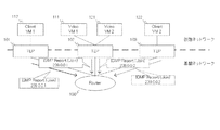
- FIG. 37 shows an example of constructing a virtual network. It is assumed that the streaming server 111 (Video VM 1) and the client terminal 112 (Client VM 1) belong to one virtual network. At this time, the TEP (Tunnel End Point) devices 101 and 102 perform encapsulation and decapsulation by tunneling technology in a virtual switch (not shown) serving as a packet transfer device (not shown) of the virtual network. And infrastructure network.
- TEP Transmission Protocol
- the virtual network ID (corresponding to “VNI” of VXLAN and “TNI” of NVGRE) of the virtual network to which the streaming server 111 (Video VM 1) and the client terminal 112 (Client VM 1) belong is 1.
- the streaming server 121 Video VM 2
- the client terminal 122 Client VM 2
- the TEP device 102 and the TEP device 103 to which each belongs belongs to construct a multicast network of the base network.
- IP multicast addresses need to be preset in each TEP device device or set from an external setting control device when each virtual network is constructed.
- the TEP device 101, the TEP device 102, and the TEP device 103 all use the same IP multicast address 239.0.0.1, multicast communication performed in the infrastructure network is communicated to all the TEP devices. .
- each TEP device decapsulates in the virtual network it can be recognized by the virtual network ID and can recognize whether or not to communicate inside (VM side).
- the original communication range of the multicast communications is different.
- the multicast communication in the base network may be performed so as to reach the entire virtual network.
- the multicast communication in the virtual network uses all the lines of the base network to which the virtual network belongs regardless of the multicast area. This impairs multicast line utilization efficiency.
- the multicast communication transmitted from the streaming server 211 it is sufficient for the multicast communication transmitted from the streaming server 211 to be able to communicate with the TEP device 202 through the TEP device 201.
- multicast communication is also performed on the TEP device 203. Is called.
- the client terminal 222 (Client VM 2-1) and the client terminal 223 (Client VM 2-2) reject the reception before the TEP device 203, in this example, so that the received terminal is correct.
- the use of the line from the Router to the TEP device 203, or the network resources ahead of it is used without meaning.
- the present invention is a packet transfer device, control device, communication system, communication method, and method that can save the IP multicast address pre-setting for performing multicast communication in a virtual network and contribute to the improvement of communication utilization efficiency of the base network
- the purpose is to provide a program.
- the packet transfer apparatus includes a multicast determination unit that determines whether or not a packet flowing through a virtual network obtained by logically dividing the base network is a packet for multicast communication.
- the packet transfer apparatus further includes a mapping in which a first multicast address used on the logically divided virtual network side is associated with a second multicast address used from a multicast address usable in the infrastructure network.
- a multicast mapping information storage unit for storing information;
- the packet transfer apparatus further includes a multicast mapping unit that assigns the second multicast address to the first multicast address of the newly generated multicast communication and manages it as the mapping information.
- the packet transfer apparatus further includes a packet encapsulation unit that encapsulates a packet flowing through the virtual network so that the packet can reach the opposite packet transfer apparatus via the infrastructure network. Then, the packet encapsulation unit performs encapsulation on a packet for multicast communication in the virtual network using a second multicast address associated with the first multicast address.
- control device that realizes the function of the packet transfer device by setting control information in the packet transfer device described above.
- a base network in which a router having a multicast function is arranged, the above-described packet transfer device, a server that provides a virtual machine that communicates with the base network and the packet transfer device, A communication system is provided.
- a packet transfer apparatus that communicates by encapsulating a packet that flows through a virtual network obtained by logically dividing a base network so that the packet can reach an opposing packet transfer apparatus via the base network, Determining whether a packet flowing through the network is a packet of multicast communication, and for the multicast communication of the virtual network, for the first multicast address used on the logically divided virtual network side, Multicast that allocates a second multicast address to be used from multicast addresses that can be used in the base network and stores the mapping information associating the first multicast address with the second multicast address. And a step of managing by a second mapping address associated with the first multicast address with respect to a multicast communication packet of the virtual network.
- a communication method is provided. This method is linked to a specific machine called a packet transfer apparatus that processes a packet flowing in a virtual network obtained by logically dividing a physical network including a base network.
- the packet flowing through the virtual network obtained by logically dividing the base network is mounted on the packet transfer apparatus that communicates by encapsulating the packet so that the packet can reach the opposite packet transfer apparatus via the base network.
- a process for determining whether or not a packet flowing through the virtual network is a packet for multicast communication, and a first multicast address used on the logically divided virtual network side for multicast communication of the virtual network.
- a second multicast address to be used is assigned from multicast addresses that can be used in the infrastructure network, and is recorded as mapping information in which the first multicast address and the second multicast address are associated with each other.
- a process managed by the multicast mapping information storage unit and a process of performing encapsulation using a second multicast address associated with the first multicast address for the multicast communication packet of the virtual network.
- a program is provided. This program can be recorded on a computer-readable (non-transient) storage medium. That is, the present invention can be embodied as a computer program product. Note that each element of the packet transfer device, the control device, the communication system, the communication method, and the program of the packet transfer device described above contributes to solving the above-described problems.
- the present invention it is possible to save labor in advance setting of an IP multicast address for performing multicast communication in a virtual network, and to contribute to improvement in communication utilization efficiency of the base network.
- FIG. 38 is a continuation diagram of FIG. 37.
- a multicast determination unit that determines whether or not a packet flowing in a virtual network obtained by logically dividing a physical network including a base network is a packet for multicast communication.
- 11 and a multicast mapping information storage unit that stores a correspondence relationship between a first multicast address in the logically divided virtual network and a second multicast address used from the multicast address that can be used in the base network 13, a multicast mapping unit 12 that assigns and manages the second multicast address to the first multicast address of the newly generated multicast communication, and packets that flow through the virtual network
- a packet capsulation section 14 for capsulating to reach the packet transfer apparatus of the counterpart through the chromatography click can be realized by the packet transfer apparatus 1A equipped with.
- the packet encapsulation unit 14 uses the second multicast address associated with the first multicast address for the packet of the multicast communication of the virtual network. Uses to encapsulate.
- the second multicast address is performed.
- group management and transfer based on the existing group management protocol are performed based on the second multicast address that has been encapsulated. For this reason, it is possible to transfer multicast packets to an appropriate range without prior setting, and the improvement of the communication utilization efficiency of the infrastructure network is achieved.
- FIG. 2 is a diagram illustrating the configuration of the packet transfer apparatus according to the first embodiment of this invention.
- a multicast determination unit 11 a multicast mapping unit 12, a multicast mapping information storage unit 13, a multicast mapping information sharing unit 15, a packet encapsulation unit 14, a communication packet to a virtual network and a base network, respectively.
- a packet transfer apparatus including a virtual network interface 18 and a base network interface 19 for transmitting and receiving is shown.
- the multicast determination unit 11 When the multicast determination unit 11 receives a communication packet from the virtual network interface 18, it determines whether the communication packet is a multicast packet or a multicast control message. When the communication packet received from the virtual network interface 18 is a multicast packet or a multicast control message, the multicast determination unit 11 sends information on the multicast packet to the multicast mapping unit 12 and requests a mapping process. At this time, when the multicast packet address is a special-purpose address such as all multicast domain addresses (224.0.0.1 in IP version 4), the multicast determination unit 11 treats the same as the broadcast, It is not a request for mapping processing. A packet determined to be neither a multicast packet nor a multicast control message is transferred to the packet encapsulation unit 14.
- the multicast mapping unit 12 When the multicast mapping unit 12 is requested to perform the mapping process of the multicast packet, the multicast mapping unit 12 refers to the multicast mapping information storage unit 13 and refers to the multicast address for the base network (second multicast address) corresponding to the multicast packet address (first multicast address). (Multicast address) is extracted or determined.
- the multicast mapping unit 12 can extract the base network multicast address (second multicast address) as a result of referring to the multicast mapping information storage unit 13, the multicast mapping unit 12 sends the extracted base network multicast address to the packet encapsulation unit 14. Requests encapsulation at (second multicast address).
- the multicast mapping unit 12 is requested to encapsulate the base network multicast address set when the virtual network is constructed.
- the multicast mapping unit 12 when the multicast mapping unit 12 is requested to perform the multicast control message mapping process from the multicast determination unit 11 or the packet encapsulation unit 14, the multicast mapping unit 12 performs the following process according to the type.
- the multicast mapping unit 12 refers to the multicast mapping information storage unit 13 and refers to the multicast address for the base network corresponding to the joined multicast address. (Second multicast address) is extracted. When the corresponding base network multicast address can be extracted, the multicast mapping unit 12 requests the packet encapsulation unit 14 to transmit a multicast join message at the base network multicast address (second multicast address).
- the multicast mapping unit 12 determines new multicast mapping information and records the correspondence relationship in the multicast mapping information storage unit 13. After the recording, the multicast mapping unit 12 requests the multicast mapping information sharing unit 15 to notify the correspondence relationship to other packet transfer apparatuses and shares it. After the sharing process, the multicast mapping unit 12 requests the packet encapsulation unit 14 to transmit a multicast control join message at the base network multicast address (second multicast address).
- the multicast mapping unit 12 refers to the multicast mapping information storage unit 13 and extracts the virtual network multicast address corresponding to the confirmed multicast address.
- the multicast mapping unit 12 requests the packet encapsulation unit 14 to transmit a multicast confirmation message at the virtual network multicast address. After the transmission, the multicast mapping unit 12 executes a multicast existence confirmation sequence (described later).
- the corresponding multicast address for the virtual network cannot be extracted.
- the packet encapsulation unit 14 Request to send a multicast confirmation message without changing the multicast address.
- the multicast mapping unit 12 executes a multicast existence confirmation sequence for all the mapping information.
- the multicast mapping unit 12 deletes the correspondence from the multicast mapping information storage unit 13. Otherwise, if the corresponding virtual network multicast address cannot be extracted, the multicast mapping unit 12 discards the received multicast confirmation message.
- the multicast mapping unit 12 refers to the multicast mapping information storage unit 13 and extracts the base network multicast address (second multicast address) corresponding to the leaving multicast address.
- the packet encapsulating unit 14 is requested to transmit a multicast leaving message at the base network multicast address.
- the multicast mapping information storage unit 13 stores at least mapping information indicating a correspondence relationship with the multicast address (second multicast address) of the base network associated with the multicast address (first multicast address) in the virtual network. To do.
- FIG. 3 is a diagram illustrating an example of mapping information held in the multicast mapping information storage unit 13. Although omitted in the example of FIG. 3, a virtual network ID or the like may be associated with each multicast address pair.
- the packet encapsulation unit 14 connects virtual networks connected by a packet transfer device functioning as a TEP device by performing encapsulation / decapsulation of packets flowing between the base network and the virtual network. Specifically, the packet encapsulation unit 14 performs the following processing.
- the packet encapsulation unit 14 when receiving a packet that is not multicast determination from the multicast determination unit 11, performs encapsulation using a communication address that can be communicated to the packet transfer device corresponding to the designated destination. Specifically, when the received packet is a unicast packet, the packet encapsulation unit 14, as in the methods of Non-Patent Documents 1 and 2, and the address to the packet transfer apparatus (strictly, the TEP apparatus) with which the other party is located Are encapsulated and transferred via the infrastructure network interface 19. If the received packet is a broadcast packet or an unknown unicast packet, the packet encapsulation unit 14 encapsulates the packet using the multicast packet address used for constructing the virtual network and transfers the packet via the infrastructure network interface 19.
- the packet encapsulation unit 14 uses the base network multicast address (second multicast address) instructed by the multicast mapping unit 12 to perform encapsulation.
- the data is transferred via the network interface 19.
- the packet encapsulation unit 14 creates a multicast control message in accordance with the request and sends it via the virtual network interface 18 or the base network interface 19. Communicate.
- the packet encapsulation unit 14 when receiving a packet from the infrastructure network interface 19, the packet encapsulation unit 14 confirms whether the packet is a packet that has been encapsulated and whether it is a virtual network to be managed by the device itself. When the received packet is a packet having an address linked to the virtual network managed by the own device, the received packet is decapsulated and communicated via the virtual network interface 18. Further, when the packet obtained by decapsulating the received packet is a mapping information sharing message, the packet encapsulation unit 14 transfers the mapping information sharing message to the multicast mapping information sharing unit 15.
- the multicast mapping information sharing unit 15 When the multicast mapping unit 12 is requested to share the multicast information, the multicast mapping information sharing unit 15 creates a mapping information sharing message describing the correspondence between the multicast address of the virtual network and the multicast address of the infrastructure network. The multicast mapping information sharing unit 15 notifies the packet encapsulation unit 14 of the mapping information sharing message, encapsulates the multicast packet address used for constructing the default virtual network, and transmits it. Thereby, the mapping information is shared with other packet transfer apparatuses.
- the multicast mapping information sharing unit 15 stores the mapping information sharing message from the packet encapsulation unit 14 in the multicast mapping information storage unit 13 via the multicast mapping unit 12.
- the multicast mapping information sharing unit 15 resolves the conflict state using a predetermined conflict resolution rule (contention resolution algorithm).
- the conflict resolution rule contention resolution algorithm
- the multicast mapping information sharing unit 15 creates a contention resolution message, encapsulates the multicast packet address used for constructing the virtual network via the packet encapsulation unit 14, and shares the multicast mapping information of other packet transfer apparatuses. Notification to the unit 15.
- the virtual network interface 18 and the base network interface 19 transmit and receive virtual network packets and base network packets, respectively. These may be realized as the same physical interface.
- FIG. 4 is a flowchart showing the operation of the packet transfer apparatus according to the first exemplary embodiment of the present invention (when receiving a packet from the virtual network interface).
- the virtual network interface 18 passes the received packet to the multicast determination unit 11.
- the multicast determination unit 11 determines whether the received packet is a multicast packet or a multicast communication control message (step S1101).
- the multicast determination unit 11 passes the received packet to the packet capsuling unit 14 to cause the encapsulation.
- the packet encapsulation unit 14 encapsulates the packet as a unicast communication to the packet transfer apparatus to which the communication partner is connected, and passes it to the base network interface 19.
- the packet encapsulation unit 14 uses the multicast address for the base network of the corresponding virtual network, and passes it to the base network interface 19.
- the infrastructure network interface 19 transmits the encapsulated packet to the infrastructure network (step S1106).
- the multicast determination unit 11 passes the packet to the multicast mapping unit 12.
- the multicast mapping unit 12 refers to the multicast mapping information storage unit 13 and sets mapping information in which the multicast address (first multicast address) of the received packet is associated with the multicast address (second multicast address) of the base network. Search is performed (step S1102).
- the multicast mapping unit 12 passes the received packet together with the mapping information to the packet encapsulation unit 14 to perform encapsulation.
- the packet encapsulation unit 14 uses the infrastructure network multicast address (second multicast address) specified by the mapping information to encapsulate the packet and passes it to the infrastructure network interface 19.
- the packet encapsulation unit 14 replaces the control multicast address information with the base network multicast address (second multicast address) designated by the mapping information, and the base network interface Pass to 19.
- the infrastructure network interface 19 transmits the encapsulated packet to the infrastructure network (step S1106).
- step S1103 when the mapping information corresponding to the received packet is not found, the multicast mapping unit 12 performs the following process according to the message type. First, when the received packet is a group leaving message, the multicast mapping unit 12 discards the packet and ends (Leave in step S1104).
- the multicast mapping unit 12 uses the multicast address (first multicast address) of the virtual network and the multicast address (second multicast address) of the base network. ) Mapping information is created and registered in the multicast mapping information storage unit 13.
- the multicast mapping unit 12 creates a mapping information sharing message for sharing the created mapping information, and requests the packet encapsulation unit 14 for encapsulation using the base network multicast address of the virtual network.
- the packet encapsulation unit 14 encapsulates the mapping information sharing message with the multicast address for the base network of the corresponding virtual network, and transmits the encapsulated packet to the base network via the base network interface 19 (step S1105). .
- the multicast mapping unit 12 requests the packet encapsulating unit 14 to convert the multicast join message, which is a received packet, with the newly created mapping information.
- the packet encapsulating unit 14 replaces the control multicast address information of the multicast join message with the base network multicast address (second multicast address) designated by the mapping information, and transfers it to the base network via the base network interface 19. Transmit (step S1106).
- a method for creating the mapping information of the multicast address there is a method in which a base multicast address that can be used in advance is prepared and one of them is selected. In that case, it is also preferable to set the usable range for each virtual network.
- the pre-setting method itself include a method of setting each device individually, and a method of setting from an external setting integrated controller when performing basic setting of a virtual network.
- step S1104 when the received packet is multicast communication (Multicast in S1104), the multicast mapping unit 12 requests the packet encapsulation unit 14 to perform encapsulation using the multicast address for the base network of the corresponding virtual network.
- the packet encapsulation unit 14 encapsulates the received multicast packet with the base network multicast address of the corresponding virtual network, and transmits the encapsulated packet to the base network via the base network interface 19 (step S1106).
- FIG. 5 is a flowchart showing the operation of the packet transfer apparatus according to the first exemplary embodiment of the present invention (when receiving a packet from the base network interface).
- the infrastructure network interface 19 when receiving a packet from the infrastructure network side, the infrastructure network interface 19 passes the received packet to the packet encapsulation unit 14.
- the packet encapsulation unit 14 confirms whether or not the received packet is encapsulated (step S1201).
- the packet encapsulation unit 14 checks whether it is a multicast control message (step S1202). If the received packet is not encapsulated and is not a multicast control message, the packet encapsulating unit 14 discards the received packet (No in step S1202).
- the packet encapsulation unit 14 passes the received packet to the multicast mapping unit 12, and requests a search for mapping information corresponding to the multicast address of the received packet.
- the multicast mapping unit 12 refers to the multicast mapping information storage unit 13 and searches for mapping information corresponding to the multicast address of the received packet (step S1203).
- the multicast mapping unit 12 transfers the received packet and the mapping information to the packet encapsulation unit 14. Similarly, when the multicast address of the received packet is the entire multicast domain address (for example, 224.0.0.1 in the above-mentioned IP version 4), the multicast mapping unit 12 A request is made to transfer the received packet without converting the address.
- the packet encapsulation unit 14 changes the control target multicast address of the received packet (multicast control message) to the virtual network multicast address (first multicast address) based on the mapping information.
- the multicast mapping unit 12 transmits the changed multicast control message to the virtual network via the virtual network interface 18.
- the packet encapsulation unit 14 executes a multicast existence confirmation sequence (Yes to S1205 in Step S1204).
- the multicast mapping unit 12 discards the received packet and ends (No in step S1204).
- step S1201 if the received packet has been encapsulated (Yes in step S1201), the packet encapsulation unit 14 decapsulates the received packet and extracts an internal message (step S1206).
- the packet encapsulation unit 14 confirms whether or not the packet after decapsulation is a multicast shared message. If the packet is not a multicast shared message (No in step S1207), the packet encapsulation unit 14 transmits the decapsulation packet to the virtual network via the virtual network interface 18 (step S1208).
- the packet encapsulation unit 14 notifies the multicast mapping information sharing unit 15.
- the multicast mapping information sharing unit 15 causes the multicast mapping unit 12 to register mapping information to the multicast mapping information storage unit 13 based on the multicast sharing message.
- the multicast mapping information sharing unit 15 can operate a mapping information arbitration algorithm.
- the arbitration by the arbitration algorithm when priority is given to the mapping information of the own device, the multicast mapping information sharing unit 15 again transmits the mapping information on the own device side to the mapping information sharing unit 15 of another packet transfer device. Do.
- the packet encapsulation unit 14 encapsulates and transmits a multicast sharing message using the base network multicast address of the virtual network (step S1209).
- mapping information arbitration algorithm there is a method of setting priority by an identifier and selecting mapping information having a high priority.
- identifiers use at least one of the device ID, device IF address, device setting priority, mapping information use multicast address, and mapping information creation time, and select the mapping information to be prioritized in the order. The method of doing is mentioned.
- decapsulation control of packets received from the infrastructure network is realized.
- Video VM 1 and Video VM 2 in FIGS. 6 to 17 are streaming servers, and Client VMs 1-1, 1-2, 2-1, and 2-2 are clients that receive streaming data from this streaming server.
- Router 300 is a router having an IP multicast function (hereinafter also referred to as “multicast router”), and at least one router 300 is disposed in the infrastructure network.
- the TEPs (devices) 301 to 303 in FIGS. 6 to 17 are respectively configured by the packet transfer device 1 of the first embodiment described above.
- the Video VM and the Client VM are virtual entities that operate using server virtualization technology on a server connected to a TEP (device).
- the streaming server 311 transmits streaming data to the clients 312 and 313 by multicast.
- the multicast address at this time is 225.0.0.1.
- the streaming server 321 transmits streaming data to the clients 322 and 323 by multicast.
- the multicast address at this time is 226.0.0.1.
- the two streaming servers and the four clients construct a single virtual network as the same group. It is assumed that 239.0.0.1 is set as the virtual network multicast address at this time. Also, the mapping use multicast address is used from 238.0.0.1 as needed.
- IGMP Internet Group Management Protocol
- the multicast control message is expressed as “IGMP [message type] [target IP address]”. Additional information attached to each is omitted.
- the message type is expressed as “Report (join)” for the join message, “Query” for the confirmation message, and “Leave” for the leave message.
- the leave confirmation message GroupSpecificQuery for Leave is the same as the confirmation message and is treated as “Query”, but it is described here that it is obvious that it may be handled separately according to the implementation method.
- the communication message is expressed as “[address] ⁇ [message] ⁇ ”. For the address, enter only the destination address. In practice, a source address, attribute information, and the like are attached, but are omitted in this example. In the case of encapsulation, this communication message becomes a message body, so it is expressed as “[capsuling address] ⁇ [encapsulated address] ⁇ message ⁇ ”.
- the mapping information sharing message is expressed as “Shared Inner [virtual network address] Outer [base network address]”. Data actually handled by the application is expressed as “DATA”.
- the streaming server 311 transmits 225.0.0.1 of IGMP Report (join) as a multicast join message.
- the TEP (packet transfer device) 301 treats the packet as reception of a packet from the virtual network (processing start in FIG. 4).
- the multicast determination unit 11 of the TEP (packet transfer apparatus) 301 determines that the packet is a multicast control message, and requests the multicast mapping unit 12 to search for mapping information (steps S1101 to S1102 in FIG. 4).
- the multicast mapping unit 12 Since the multicast mapping unit 12 could not find the corresponding mapping information, it grasps the message type and confirms that it is a subscription message (Report). For this reason, the multicast mapping unit 12 selects 238.0.0.1 as the base network multicast address from the mapping use multicast address, and creates mapping information. The multicast mapping unit 12 stores the created mapping information in the multicast mapping information storage unit 13 (see the first entry in FIG. 3).
- the multicast mapping unit 12 passes the created mapping information to the multicast mapping information sharing unit 15 and requests sharing of mapping information to another TEP (packet transfer device).
- the multicast mapping information sharing unit 15 creates a mapping information sharing message “Shared Inner 225.0.0.1 Outer 238.0.0.1” and forwards it to the packet encapsulation unit 14 using the multicast address for virtual network construction. Ask.
- the packet encapsulation unit 14 performs the multicast communication by encapsulating with the virtual network construction multicast address 239.0.0.1.
- the multicast router 300 transfers the encapsulated mapping information sharing message to the other TEP devices 302 and 303 belonging to the virtual network (steps S1103 to S1105 in FIG. 4).
- the TEP devices 302 and 303 that have received the encapsulated mapping information sharing message handle the mapping information sharing message as packet reception from the infrastructure network (start of processing in FIG. 5).
- the packet encapsulation unit 14 performs decapsulation because the target is the encapsulated packet, and extracts the mapping information sharing message “Shared Inner 225.0.0.1 Outer 238.0.0.1” (S1201 in FIG. 5). To S1206). Since the decapsulation result is a mapping information sharing message, the packet encapsulation unit 14 notifies the multicast mapping unit 12 and stores the mapping information in the multicast mapping information storage unit 13 (S1207 to S1209 in FIG. 5). As a result, multicast mapping information is shared.
- FIG. 6 shows a flow from when the multicast join message (IGMP Report (join)) is transmitted from the streaming server 311 until mapping information is generated and shared with another TEP (packet transfer device) by the mapping information sharing message. Represents.
- IGMP Report join
- the multicast mapping unit 12 of the TEP (packet transfer apparatus) 301 passes the received packet “IGMP Report (join) 225.0.0.1” and the created mapping information to the packet encapsulation unit 14. Based on the received information, the packet encapsulation unit 14 converts the multicast control information into the base network side multicast address, and creates “IGMP Report (join) 238.0.0.1”. The packet encapsulation unit 14 transmits the converted multicast control message to the infrastructure network side.
- FIG. 7 shows a state in which a TEP (packet transfer apparatus) 301 has transmitted a converted multicast control message to the infrastructure network side.
- the multicast address 225.0.0.1 of the virtual network is associated with 238.0.0.1 of the base network, and only the TEP device 301 belongs to the multicast router 300.
- the streaming server 311 when the streaming server 311 tries to flow the streaming data, the message “225.0.0.1 ⁇ DATA ⁇ ” flows and arrives at the TEP (packet transfer device) 301.
- the TEP (packet transfer device) 301 treats the packet as reception of a packet from the virtual network (processing start in FIG. 4).
- the multicast determination unit 11 of the TEP (packet transfer apparatus) 301 determines that the packet is a multicast control message, and requests the multicast mapping unit 12 to search for mapping information (steps S1101 to S1102 in FIG. 4).
- the multicast mapping unit 12 passes the mapping information and the received packet to the packet encapsulation unit 14.
- the packet encapsulation unit 14 performs the encapsulation based on the received information, creates a message “238.0.0. 1 ⁇ 225.0.0.1 ⁇ DATA ⁇ ”, and sends it to the infrastructure network. Since the multicast router 300 belongs only to the TEP (packet transfer device) 301 to the multicast group 238.0.0.1, the multicast router 300 does not perform a new transfer (see FIG. 8).
- the client 312 wishes to receive multicast data from the streaming server 311.
- the client 312 transmits IGMP Report (join) 225.0.0.1 as a multicast join message.
- the TEP (packet transfer apparatus) 302 treats the packet as reception of a packet from the virtual network (processing start in FIG. 4).
- the multicast determination unit 11 of the TEP (packet transfer apparatus) 302 determines that the packet is a multicast control message, and requests the multicast mapping unit 12 to search for mapping information (steps S1101 to S1102 in FIG. 4). Since the corresponding mapping information is found, the multicast mapping unit 12 passes the mapping information to the packet encapsulation unit 14.
- the packet encapsulation unit 14 Based on the received information, the packet encapsulation unit 14 converts the multicast address of the multicast control information into a multicast address on the infrastructure network side, and creates “IGMP Report (join) 238.0.0.1”. The packet encapsulation unit 14 sends the converted multicast control message to the base network side. As a result, the TEP device 302 also joins the multicast group 238.0.0.1 (see FIG. 9).
- the streaming data “225.0.0.1 ⁇ DATA ⁇ ” sent out by the streaming server 311 is encapsulated by the TEP (packet transfer apparatus) 301 as shown in FIG. 10, and the message “238.0. 0.1 ⁇ 225.0.1 ⁇ DATA ⁇ ], and reaches the TEP device 302 through the multicast router 300.
- the TEP (packet transfer device) 302 that has received the encapsulated message “238.0.0.1 ⁇ 225.0.1. ⁇ DATA ⁇ ” treats the packet as being received from the base network (processing in FIG. 5). start).
- the packet encapsulating unit 14 performs decapsulation because the target is the encapsulated packet, and extracts the multicast communication message “225.0.0.1 ⁇ DATA ⁇ ” (S1201 to S1206 in FIG. 5). Since the decapsulation result is not a mapping information sharing message, the packet encapsulation unit 14 sends it to the virtual network (S1207 to S1208 in FIG. 5). Thereby, the streaming data transmitted from the streaming server 311 reaches the client 312 as multicast data of the same virtual network (see FIG. 10).
- the group having the multicast address 226.0.0.1 to which the streaming server 321 joins and the client 323 joins is associated with the multicast address 238.0.0.2 of the base network (
- the multicast addresses on the two virtual networks are encapsulated with the multicast addresses of the base network at the entrance TEP (packet transfer device), and then transferred to the destination TEP (packet transfer device). Again, it shows a state of being decapsulated and delivered to the client.
- communication of a multicast group having a new multicast address 226.0.0.1 is transferred only between TEPs (packet transfer apparatuses) 301 and 303, and is sent to TEP (packet transfer apparatus) 302. Does not flow.
- the multicast communication on the virtual network side can be controlled in the same manner as the multicast communication in the base network.
- the multicast address in the base network is 239.0.0.1 for the entire virtual network, 238.0.0.1 for streaming of the streaming server 311, and 238.0.0.2 for streaming of the streaming server 321. Therefore, it can be used as load distribution or QoS control.
- a multicast router prompts communication of a join message IGMP Report by issuing a query to all multicast domain addresses (224.0.0.1 in IP version 4). As shown in FIG. 12, the multicast router 300 creates “IGMP Query 0.0.0.0” with a destination address of 224.0.0.1 and transmits it to all TEPs (packet transfer apparatuses). .
- TEPs packet transfer apparatuses 301, 302, and 303 handle the multicast control message as reception of packets from the base network (start processing in FIG. 5).
- the packet encapsulating unit 14 requests the multicast mapping unit 12 to extract mapping information because the received packet is not an encapsulated packet (S1201 to S1203 in FIG. 5).
- the multicast mapping unit 12 reports to the packet encapsulation unit 14 that there is no mapping information. However, since the packet encapsulation unit 14 has all multicast addresses 224.0.0.1, the packet encapsulation unit 14 treats the information as it is and transmits it to the virtual network (S1204 to S1205 in FIG. 5).
- the Query message can be delivered to each terminal or an arbitrary terminal of the virtual network, and the Report can be transmitted.
- the multicast mapping unit 12 executes a multicast existence confirmation sequence. If the presence of a multicast client cannot be confirmed by the multicast existence confirmation sequence, that is, if the group is not reported in the report, the corresponding mapping information is deleted from the multicast mapping information storage unit 13.
- a leave message is transmitted.
- the TEP (packet transfer apparatus) 302 treats the packet as reception of a packet from the virtual network (processing start in FIG. 4).
- the multicast determination unit 11 of the TEP (packet transfer apparatus) 302 determines that the packet is a multicast control message, and requests the multicast mapping unit 12 to search for mapping information (steps S1101 to S1102 in FIG. 4).
- the multicast mapping unit 12 passes the mapping information to the packet encapsulation unit 14.
- the packet encapsulation unit 14 converts the multicast control information into a base network side multicast address based on the received information, and creates “IGMP Leave 238.0.0.1”.
- the packet encapsulation unit 14 sends the converted multicast control message to the infrastructure network side.
- the multicast router 300 receives an opportunity to leave the multicast group 238.0.0.1 (see FIG. 13).
- the multicast router 300 that has received the multicast leave message transmits, as a response, an existence confirmation message “IGMP Query 238.0.0.1” for confirming whether or not there is a member in the corresponding group.
- the TEP (packet transfer apparatus) 302 that has received the leave confirmation message handles the packet as reception of a packet from the base network (start of processing in FIG. 5). Since the received packet is not a packet that has been encapsulated, the packet encapsulation unit 14 requests the multicast mapping unit 12 to search for mapping information (S1201 to S1203 in FIG. 5). The multicast mapping unit 12 finds the corresponding mapping information and notifies the packet encapsulation unit 14 of it.
- the packet encapsulation unit 14 performs message conversion using the mapping information so that the multicast control address is treated as a multicast address on the virtual network side.
- the packet encapsulation unit 14 converts it into a leave confirmation message with “IGMP Query 225.0.0.1” and transmits it to the virtual network. (S1204 to S1205).
- the Report can be transmitted to each terminal or any terminal of the virtual network.
- the multicast mapping unit 12 also executes the multicast existence confirmation sequence at this timing.
- the corresponding mapping information is deleted from the multicast mapping information storage unit 13 (for example, 1 in FIG. 3). Delete the second entry).
- mapping of mapping information Next, a specific example of mediation of mapping information will be described with reference to FIGS. It is assumed that the client 313 newly joins the group with the multicast address 225.0.0.1 after the client 312 leaves. At this time, since the mapping information has already been deleted, it is assumed that TEP (packet transfer apparatus) 302 newly maps to 238.0.0.3. As shown in FIG. 15, the TEP (packet transfer apparatus) 302 sends a mapping information sharing message “Shared Inner 225.0.0.1 Outer 238.0.0. 3 ”is transmitted (see FIG. 15).
- the TEP (packet transfer device) 301 selects mapping information to be prioritized based on the arbitration rule or the arbitration algorithm described above. In this case, it is assumed that priority is given to 238.0.0.1 as the multicast address order.
- the TEP (packet transfer device) 301 transmits the mapping information sharing message “Shared Inner 225.0.0.1 Outer 238.0.0.1” again to the TEP (packet transfer device) 302 and 303 ( (See FIG. 16).
- the TEP (packet transfer apparatus) 302 updates the mapping information. Thereafter, the TEP (packet transfer apparatus) 302 can reconcile the client 313 with the new multicast group (state shown in FIG. 17).
- the multicast router 300 is used, but it can also be realized as a plurality of multicast router groups.
- the multicast router 300 can also be realized as a network device group including an L2 switch that can specify a communication range for an IGMP message using IGMP snooping, CGMP (Cisco Group Management Protocol), or the like.
- the TEP packet transfer apparatus
- the multicast space of the virtual network can be mapped to the multicast space of the base network
- the range of multicast communication line use can be limited to a necessary range. This improves the efficiency of communication line usage.
- FIG. 18 is a diagram illustrating a configuration of a packet transfer device and a multicast mapping management device according to the second embodiment of this invention.
- a configuration in which a multicast mapping management device 26 is added outside the packet transfer device in place of the multicast mapping information sharing unit 15 is shown. Since the configuration of the other packet transfer apparatus 1B is substantially the same as that of the packet transfer apparatus 1 of the first embodiment, the difference will be mainly described below.
- the multicast mapping unit 22 of the second embodiment requests the multicast mapping management device 26 to inquire the mapping information.
- the multicast mapping unit 22 of the second embodiment requests the multicast mapping management device 26 to delete the mapping information.
- the multicast mapping management device 26 uses mapping information as shown in FIG. 19 to maintain and manage mapping information associated with member information. For example, when the multicast mapping management device 26 is requested to inquire mapping information from the multicast mapping unit 22 of any packet transfer device including the packet transfer device 1B, if the corresponding mapping information is not held, Any one of the usable multicast addresses is selected, and mapping information with the multicast address of the requesting virtual network is created. Further, the member of the request source is added to the member field of the created mapping information. The created mapping information is notified to the multicast mapping unit 22 of the requesting packet transfer apparatus.
- the multicast mapping management device 26 when requested to inquire mapping information from the multicast mapping unit 22 of an arbitrary packet transfer device, if it holds the corresponding mapping information, it requests the member field of the mapping information. Add the original member. Then, the mapping information is notified to the multicast mapping unit 22 of the requesting packet transfer apparatus.
- the multicast mapping management device 26 when the multicast mapping management device 26 is requested to release the mapping information from the multicast mapping unit 22 of any packet transfer device, the multicast mapping management device 26 deletes the requesting member from the member field of the stored mapping information. When all members in the member field of the mapping information are gone, the multicast mapping management device 26 deletes the mapping information.
- mapping information inquiry and deletion request can be realized using communication of the infrastructure network.
- mapping management device 26 that functions as an aggregation management point of mapping management information, it is possible to exclude the sharing work and the arbitration work of the mapping work.
- FIG. 20 is a flowchart showing the operation of the packet transfer apparatus 1B according to the second exemplary embodiment of the present invention (when receiving a packet from the virtual network interface).
- the operation of the packet transfer apparatus shown in FIG. 20 is almost the same as the flowchart shown in FIG. The difference is that the creation and sharing of the mapping information in step S1105 results in a mapping information inquiry and response reception to the multicast mapping management device 26 (see step S1105A).
- FIG. 21 is a flowchart showing the operation of the multicast mapping management apparatus when receiving an inquiry about the mapping information.
- the multicast mapping unit 22 receives the multicast join message, if there is no mapping information corresponding to the multicast address specified in the multicast join message, the multicast mapping unit 26 inquires the multicast mapping management device 26 about the mapping information. (Start processing in FIG. 21).
- the inquiry information includes at least a virtual network identifier and a multicast address of the virtual network.
- the multicast mapping management device 26 If the multicast mapping management device 26 does not hold mapping information corresponding to the multicast address of the requesting virtual network (No in step S2101), the multicast mapping management device 26 newly selects any one of the multicast addresses that can be used in the infrastructure network. Mapping information with the multicast address of the requesting virtual network is created (step S2102 in FIG. 21).
- the multicast mapping management device 26 uses the identifier of the requesting packet transfer device as a member (user) for the existing mapping information (Yes in step S2101) or the mapping information created in step S2102. Registration is performed (step S2103).
- the multicast mapping management device 26 responds to the multicast mapping unit 22 of the requesting packet transfer device with the existing mapping information (Yes in step S2101) or the mapping information created in step S2102. (Step S2104).
- the multicast mapping unit 22 that has received the mapping information stores the mapping information in the multicast mapping information storage device 13. After that, based on the received packet and the mapping information returned as a response, the packet encapsulation unit 14 is requested to convert the packet message (step S1106 in FIG. 20).
- the multicast mapping unit 22 can leave the creation of mapping information and the sharing of the mapping information to the multicast mapping management device 26.
- FIG. 22 is a flowchart showing the operation of the packet transfer apparatus according to the second exemplary embodiment of the present invention (when receiving a packet from the base network interface).
- the difference from the operation of the packet transfer apparatus of the first embodiment shown in FIG. 5 is that the mapping information arbitration process shown in step 1209 in FIG. 5 is deleted, and that the multicast confirmation sequence in step S1205 is executed.
- step S1210 for requesting the multicast mapping management device 26 to delete the mapping information when the mapping information on the own device side is deleted is added.
- the multicast mapping unit 22 deletes the mapping information from the multicast mapping information storage unit 13 when detecting a multicast group in which the presence of a member cannot be confirmed. Thereafter, the multicast mapping unit 22 requests the multicast mapping management device 26 to delete the mapping information (start processing in FIG. 23).
- the request to delete the mapping information includes at least mapping information deleted on the packet transfer apparatus 1B side.
- FIG. 23 is a flowchart showing the operation of the multicast mapping management apparatus when receiving a request for deleting the mapping information.
- the multicast mapping management device 26 deletes the identifier of the requesting packet transfer device registered as a member (user) from the member field of the mapping information held by itself (step S2201). ).
- the multicast mapping management device 26 deletes the mapping information (step S2203).
- mapping information that is no longer necessary in the multicast mapping management device 26 is organized.
- Video VM 1 and Video VM 2 are streaming servers, and Client VMs 1-1, 1-2, 2-1, and 2-2 receive streaming data from this streaming server.
- the router 400 is a multicast router having an IP multicast function.
- the TEPs (devices) 401 to 403 in FIGS. 24 to 30 are respectively configured by the packet transfer device 1B of the second embodiment described above.
- a significant difference from the first embodiment is that a Connection Server (hereinafter referred to as “connection server”) 409 that functions as the multicast mapping management device 26 is added.
- mapping information query is expressed as “Shared query [virtual network multicast address]”
- response is expressed as “Shared map [virtual network multicast address] [base network multicast address]”.
- a TEP (packet transfer device) 401 performs multicast address mapping processing. However, since the mapping information is not held at this point, the multicast mapping unit 22 of the TEP (packet transfer apparatus) 401 makes an inquiry about the mapping information to the connection server 409, and therefore the inquiry message “Shared query 225.0.0. .1 "is transmitted (see FIG. 24).
- connection server 409 Since the connection server 409 does not yet hold the mapping information, the connection server 409 selects 238.0.0.1 as the multicast that can be used in the infrastructure network and creates the mapping information (No to S2102 in steps S2101 in FIG. 21). . Further, the connection server 409 stores a TEP (packet transfer device) 401 as a member of the created mapping information (step S2103). The connection server 409 creates a mapping information response message “Shared map 225.0.0.1 238.0.0.1” in order to respond to the TEP (packet transfer device) 401 with the created mapping information. And transmit (see FIG. 25).
- TEP packet transfer device
- the TEP (packet transfer device) 401 Since the TEP (packet transfer device) 401 has obtained the mapping information, it stores it in the multicast mapping information storage unit 13 of the own device. Further, the TEP (packet transfer apparatus) 401 converts the join message into “IGMP Report (join) 238.0.0.1” and transmits it to the base network side. As a result, the TEP (packet transfer apparatus) 401 has joined the multicast address of 238.0.0.1 as the infrastructure network (see FIG. 26).
- the TEP (packet transfer device) 402 performs mapping of the multicast address. Process. However, at this point, the TEP (packet transfer device) 402 does not hold the corresponding mapping information. Therefore, the multicast mapping unit 22 of the TEP (packet transfer device) 402 sends an inquiry message “Shared query 225.0.0.1” to the connection server 409 to inquire about mapping information (FIG. 27). reference).
- connection server 409 Since the connection server 409 that has received the inquiry holds the corresponding mapping information, a TEP (packet transfer device) 402 is added as a member of the mapping information (No to S2103 in steps S2101 in FIG. 21, FIG. 19 first entry).
- the connection server 409 creates a mapping information response message “Shared map 225.0.0.1 238.0.0.1” in order to respond to the mapping information to the TEP (packet transfer device) 402. (See FIG. 28).
- the TEP (packet transfer device) 402 Since the TEP (packet transfer device) 402 has obtained the mapping information, it stores it in the multicast mapping information storage unit 13 of its own device. Further, the TEP (packet transfer device) 402 converts the join message into “IGMP Report (join) 238.0.0.1” and transmits it to the base network side. As a result, the TEP (packet transfer device) 402 has joined the multicast address of 238.0.0.1 as the infrastructure network (see FIG. 29).
- the subsequent multicast communication using 225.0.0.1 of the streaming server 411 is encapsulated with the multicast address of the base network by the TEP (packet transfer device) 401 on the entrance side, and then the destination address.
- the data is transferred to a TEP (packet transfer device) 402, decapsulated again, and delivered to the client (see FIG. 30).
- the load of sharing mapping information and the load of mediation can be reduced.
- the reason is that a multicast mapping management device 26 is provided, and a configuration is adopted in which the mapping information is collectively managed.
- FIG. 31 is a diagram illustrating a configuration of a packet transfer apparatus according to the third embodiment of this invention. Referring to FIG. 31, there is shown a configuration in which a mapping information integration unit 37 is added to the configuration of the packet transfer apparatus according to the first embodiment shown in FIG.
- the mapping information integration unit 37 integrates the mapping information stored in the multicast mapping information storage unit 13 at a predetermined opportunity.
- the multicast mapping unit 12 performs registration and deletion of synchronized multicast information with other packet transfer devices via the multicast mapping information sharing unit 15 based on information of packet transfer devices that share preset mapping information. Do.
- the mapping information integration unit 37 refers to the multicast mapping information storage unit 13, searches for mapping information that is common to the set of packet transfer apparatuses being used, and integrates the searched mapping information. When the mapping information is integrated, the mapping information integration unit 37 notifies the multicast mapping unit 12 of the changed mapping information as a result of the integration.
- mapping information having the same multicast notification range can be unified with the multicast address of either base network.
- mapping information having a narrower multicast notification range than other mapping information can be unified to a multicast address of a base network having a wider multicast notification range.
- Examples of the predetermined trigger include the following. (1) Periodic check (2) When the base multicast address is exhausted, or when the number of usable base multicast addresses falls below a certain level (3) When the mapping information is updated
- the multicast mapping unit 12 updates the mapping information in the multicast mapping information storage unit 13 and receives other packets through the multicast mapping information sharing unit 15 when the mapping information changed by the integration is transmitted from the mapping information integration unit 37. Requests the transfer apparatus to update the mapping information synchronously.
- the multicast mapping unit 12 changes the multicast subscription address based on the mapping information changed by the integration.
- the multicast mapping unit 12 outputs a leave message in which the base multicast address is set.
- FIG. 32 is a diagram illustrating configurations of a packet transfer device and an external device according to the fourth embodiment of this invention. Referring to FIG. 32, there is shown a configuration in which a mapping information integration device 47 is added to the configuration in which the packet transfer device 1D and the multicast mapping management device 46 are connected as in FIG. In the example of FIG. 32, the multicast mapping management device 46 and the mapping information integration device 47 are shown as separate devices, but they may be integrated and realized by the same device.
- the mapping information integration device 47 acquires the mapping information from the multicast mapping management device 46, and searches for mapping information that is common to a set of packet transfer devices participating in the group. When the mapping information common to the group of packet transfer apparatuses participating in the group is found, the mapping information integration apparatus 47 requests the multicast mapping management apparatus 46 to integrate the mapping information.
- the multicast mapping management device 46 When the mapping information is integrated, the multicast mapping management device 46 notifies the changed mapping information as a result of the integration to the multicast mapping unit 22 of the packet transfer device affected by the integration of the mapping information.
- the multicast mapping unit 22 Upon receiving the notification, the multicast mapping unit 22 updates the mapping information in the multicast mapping information storage unit 13. In addition, the multicast mapping unit 22 changes the multicast subscription address based on the changed mapping information.
- Video VM 1, Video VM 2, and Video VM 3 are streaming servers, and Client VMs 1-1, 2-1, 2-2, and 3-1 are streaming from these streaming servers.
- the client 500 is a client that receives data
- the Router 500 is a multicast router having an IP multicast function.
- TEPs (devices) 501 to 503 in FIGS. 33 to 36 are respectively configured by the packet transfer device 1D of the fourth embodiment described above.
- a connection server (hereinafter referred to as “connection server”) 509 functions as a multicast mapping management device 46 and a mapping information integration device 47.
- connection server functions as a multicast mapping management device 46 and a mapping information integration device 47.
- Other terms and message expressions are the same as those in the first embodiment, and a description thereof will be omitted.
- the mapping information stored in the multicast mapping management device 46 of the connection server 509 is as shown in FIG. That is, 225.0.0.1 is mapped to 238.0.0.1, and TEPs (packet transfer apparatuses) 501 and 502 belong to it. 226.0.0.1 is mapped to 238.0.0.2, and TEPs (packet transfer apparatuses) 501 and 503 belong to it. 227.0.0.1 is mapped to 238.0.0.3, and TEPs (packet transfer apparatuses) 501 and 502 belong to it.
- the mapping information integration device 47 of the connection server 509 receives the mapping information from the multicast mapping management device 46 and searches for mapping information that can be integrated. As a result, in this example, it is determined that the mapping information for 225.0.0.1 and the mapping information for 227.0.0.1 can be integrated because the members are equal. When the mapping information integration device 47 of the connection server 509 selects these two pieces of mapping information as integration targets, the mapping information integration device 47 requests the multicast mapping management device 46 of the connection server 509 to integrate the mapping information. In this example, it is assumed that mapping information for 227.0.0.1 is requested to be integrated with mapping information for 225.0.0.1 into the same base multicast address.
- the multicast mapping management device 46 of the connection server 509 sends a mapping information update message “Shared change 227. to the TEPs (packet transfer devices) 501 and 502 that are members of the mapping information before and after the integration. "0.0.1 238.0.0.1" is transmitted.
- the multicast mapping units 22 of the TEPs (packet transfer apparatuses) 501 and 502 update the mapping information based on the mapping information update message. This unifies the encapsulation for 225.0.0.1 and 227.0.0.1 to 238.0.0.1. (See FIG. 34).
- the multicast mapping unit 22 of the TEPs (packet transfer apparatuses) 501 and 502 has the member of 238.0.0.3 used in the original 227.0.0.1 when the mapping information is updated. Therefore, the leaving process can be started by transmitting a leaving message “IGMP Leave 238.0.0.3” via the packet encapsulation unit 14 (see FIG. 35).
- the base multicast address mapped to 225.0.0.1 and 227.0.0.1 is unified to 238.0.0.1.
- those with overlapping communication ranges can be communicated with the same multicast address on the base network side.
- FIG. 36 it is written that the clients 512 and 532 receive only their own multicast communication, but such communication control can be realized by installing the IGMP snooping technology in the TEP device. .
- IP multicast a purpose of use such as a global IP multicast address area is generally defined.
- the influence of communication with the outside may become a problem.
- the multicast router is connected to the external network only for specific multicast communication, and the influence of the external machine is separated by setting the filter to drop the multicast address that uses the mapping purpose. be able to.
- the packet transfer apparatuses 1, 1 ⁇ / b> A to 1 ⁇ / b> D described above can also be realized by the OpenFlow switch of Non-Patent Document 3.
- the functions of the packet transfer apparatuses 1, 1A to 1D described above are realized by the central control apparatus setting control information in each apparatus.
- the above-described function for determining whether a packet is a multicast packet sets a flow entry that associates a match condition for identifying the multicast packet with an operation (instruction) at that time in the packet transfer apparatuses 1 and 1A to 1D. Can be realized.
- each unit (processing means) of the packet transfer apparatus shown in each figure can be realized by a computer program that causes the computer constituting the packet transfer apparatus to execute the above-described processes using its hardware.
- a packet transfer apparatus comprising a multicast mapping information sharing unit for notifying another packet transfer apparatus of a change in mapping information stored in the multicast mapping information storage unit.
- the packet transfer device of the second form When the multicast mapping information sharing unit receives a notification of a change in mapping information that conflicts with the mapping information held on the own device side from another packet transfer device, the packet transfer that performs an arbitration operation according to a predetermined rule apparatus.
- the multicast mapping unit uses a multicast address provided from an external multicast mapping management device as the second multicast address.
- the multicast mapping unit manages the members participating in the multicast group in association with the mapping information, and when there are no more members, the multicast mapping unit requests the multicast mapping management apparatus to delete the mapping information. apparatus.
- the multicast mapping unit manages the members participating in the multicast group in association with the mapping information
- the packet transfer device further includes: A packet transfer apparatus comprising: a mapping information integration unit that selects, from among the mapping information, mapping information that overlaps members participating in a multicast group and shares the second multicast address.
Landscapes
- Engineering & Computer Science (AREA)
- Computer Networks & Wireless Communication (AREA)
- Signal Processing (AREA)
- Multimedia (AREA)
- Data Exchanges In Wide-Area Networks (AREA)
- Small-Scale Networks (AREA)
Abstract
Description
[関連出願についての記載]
本発明は、日本国特許出願:特願2014-005637号(2014年 1月16日出願)に基づくものであり、同出願の全記載内容は引用をもって本書に組み込み記載されているものとする。
本発明は、パケット転送装置、制御装置、通信システム、通信方法及びプログラムに関し、特に、基盤ネットワーク(Substrate Network)上に構成された仮想ネットワーク上のマルチキャストパケットを取り扱うパケット転送装置、制御装置、通信システム、通信方法及びプログラムに関する。
[Description of related applications]
The present invention is based on a Japanese patent application: Japanese Patent Application No. 2014-005637 (filed on January 16, 2014), and the entire description of the application is incorporated herein by reference.
The present invention relates to a packet transfer apparatus, a control apparatus, a communication system, a communication method, and a program, and in particular, a packet transfer apparatus, a control apparatus, and a communication system that handle multicast packets on a virtual network configured on a base network (Substrate Network). The present invention relates to a communication method and a program.
近年、大規模データセンター環境、また、その上での仮想計算機環境の利用が増え、仮想計算機環境上でのSDN(Software-Defined Network)構築が行われている。このとき、VLAN(Virtual Local Area Network)などでは、ネットワーク装置の区画資源の少なさや、ネットワーク機器の設定の複雑さという問題が発生するため、エッジオーバレイを構築するためのオーバレイネットワーク技術が使用される。 In recent years, the use of large-scale data center environments and virtual computer environments thereon has increased, and SDN (Software-Defined Network) construction on virtual computer environments has been carried out. At this time, in the case of VLAN (Virtual Local Area Network) and the like, there are problems such as a small number of partition resources of the network device and the complexity of setting of the network device, so the overlay network technology for constructing the edge overlay is used. .
エッジオーバレイネットワーク技術としては、VXLAN (Virtual eXtensible Local Area Network) や NVGRE (Network Virtualization using Generic Routing Encapsulation)などのトンネリング技術が用いられる(非特許文献1、2参照)。これらの技術は、仮想計算機上に構築される仮想ネットワークの通信をカプセル化して、仮想計算機環境を構築しているネットワーク機器で構成される基盤ネットワーク(Substrate Network;物理ネットワーク)に通信を流す。これらトンネリング技術では、カプセリングの際に、仮想ネットワークIDを付加することで、仮想的に、仮想ネットワークの区画資源を増やすことが可能となっている。また、これらトンネリング技術では、基盤ネットワークの通信を用いることで、ネットワーク機器への設定の負担を削減している。 Edge overlay network technologies include tunneling technologies such as VXLAN (Virtual eXtensible Local Area Network) and NVGRE (Network Virtualization using Generic Routing Encapsulation) and other non-patent reference technologies such as NRTRE. These technologies encapsulate communication of a virtual network constructed on a virtual computer, and flow the communication to a basic network (Substrate Network: physical network) composed of network devices constructing a virtual computer environment. In these tunneling technologies, it is possible to virtually increase the partition resources of the virtual network by adding a virtual network ID at the time of encapsulation. Moreover, in these tunneling technologies, the setting burden on the network device is reduced by using the communication of the base network.
しかしながら、これらのトンネリング技術は、ブロードキャスト、マルチキャスト、Unknown ユニキャストに関しては、その処理を詳細に規定しておらず、基盤ネットワークのIP(Internet Protocol)マルチキャスト技術を用いることが定められている程度である。このIPマルチキャストアドレスは、共有されることもあるが、通常、仮想ネットワークIDごとに設定され、構築する仮想計算機環境のネットワーク、即ち、対象仮想ネットワークの全域に届けられている(非特許文献1の「4.2. Broadcast Communication and Mapping to Multicast」、非特許文献2の「4.1. Broadcast and Multicast Traffic」参照)。
However, these tunneling technologies do not stipulate the processing in detail for broadcast, multicast, and unknown unicast, and are to the extent that the IP (Internet Protocol) multicast technology of the base network is used. . Although this IP multicast address may be shared, it is usually set for each virtual network ID and delivered to the entire network of the virtual machine environment to be constructed, that is, the entire target virtual network (Non-Patent Document 1). (See “4.2. Broadcastcast Communication and Mapping to Multicast”, Non-Patent
特許文献1には、TRILL(Transparent Interconnection of Lots of Links)ヘッダと呼ばれるヘッダによりパケットをカプセル化する構成に用いるスイッチが開示されている。同文献によると、このスイッチは、マルチキャストパケットと関連付けられるソースアドレス、マルチキャストアドレス、およびマルチキャストツリー識別子フィールドに基づいて、内部マルチキャストグループ識別子を判定するように構成される判定機構と、該内部マルチキャストグループ識別子に基づいて該マルチキャストパケットを転送するように構成される転送機構とを備えている。
非特許文献3は、オープンフローと呼ばれるネットワーク制御技術のホワイトペーパーである。オープンフローを用いることで、オープンフロースイッチをトンネリング技術のTEP装置として機能させることもできる。 Non-Patent Document 3 is a white paper on network control technology called OpenFlow. By using OpenFlow, the OpenFlow switch can also function as a TEP device using tunneling technology.
以下の分析は、本発明によって与えられたものである。図37に仮想ネットワークを構築する一例を示す。ストリーミングサーバ111(Video VM 1)とクライアント端末112(Client VM 1)が1つの仮想ネットワークに属するものとする。このとき、仮想ネットワークのパケット転送装置(不図示)となる仮想スイッチ(不図示)内において、TEP(Tunnel End Point)装置101、102がトンネリング技術によりカプセル化、デカプセル化を行うことで、仮想ネットワークと基盤ネットワークとの分離を行う。
The following analysis is given by the present invention. FIG. 37 shows an example of constructing a virtual network. It is assumed that the streaming server 111 (Video VM 1) and the client terminal 112 (Client VM 1) belong to one virtual network. At this time, the TEP (Tunnel End Point)
前記ストリーミングサーバ111(Video VM 1)とクライアント端末112(Client VM 1)の属する仮想ネットワークの仮想ネットワークID(VXLANの「VNI」、NVGREの「TNI」に相当)が1であるとする。このとき、仮想ネットワークID=1に対し、IPマルチキャストアドレス(図例では239.0.0.1)を設定し、各々の属するTEP装置102及びTEP装置101が基盤ネットワークのマルチキャスト網を構築する。今後、仮想ネットワークID=1に属する端末におけるブロードキャスト、マルチキャスト、Unknown ユニキャストは、基盤ネットワークでは、このIPマルチキャストアドレス239.0.0.1を用いて通信される。
It is assumed that the virtual network ID (corresponding to “VNI” of VXLAN and “TNI” of NVGRE) of the virtual network to which the streaming server 111 (Video VM 1) and the client terminal 112 (Client VM 1) belong is 1. At this time, an IP multicast address (239.0.0.1 in the example) is set for the virtual network ID = 1, and the
同様に、ストリーミングサーバ121(Video VM 2)とクライアント端末122(Client VM 2)が仮想ネットワークID=2の別の仮想ネットワークに属するとする。このとき、仮想ネットワークID=2に対し、IPマルチキャストアドレス(図例では239.0.0.2)を設定し、各々の属するTEP装置102及びTEP装置103が基盤ネットワークのマルチキャスト網を構築する。
Similarly, it is assumed that the streaming server 121 (Video VM 2) and the client terminal 122 (Client VM 2) belong to another virtual network with the virtual network ID = 2. At this time, an IP multicast address (239.0.0.2 in the figure) is set for the virtual network ID = 2, and the
これらのIPマルチキャストアドレスは、各仮想ネットワークを構築する際に、各々のTEP装置デバイスに事前設定したり、外部設定制御装置から設定したりする必要がある。また、このIPマルチキャストアドレスは、明確に分割しない場合、同一マルチキャストアドレスを用いることもできる。例えば、図37の例では、仮想ネットワークID=2用に239.0.0.2を用いたが、仮想ネットワークID=1に対して設定されている239.0.0.1を用いても構わない。このとき、TEP装置101、TEP装置102、TEP装置103すべてが同一IPマルチキャストアドレス239.0.0.1を用いるため、基盤ネットワークで行われるマルチキャスト通信はすべてのTEP装置に通信されることになる。各TEP装置が仮想ネットワーク内にデカプセリングするときに仮想ネットワークIDで認識し、内部(VM側)に通信するかどうかを認識することができる。
These IP multicast addresses need to be preset in each TEP device device or set from an external setting control device when each virtual network is constructed. In addition, when the IP multicast address is not clearly divided, the same multicast address can be used. For example, in the example of FIG. 37, 239.0.0.2 is used for virtual network ID = 2, but 239.0.0.1 set for virtual network ID = 1 may be used. I do not care. At this time, since the
上記のように仮想ネットワーク内で複数のマルチキャスト通信を扱うとき、それらマルチキャスト通信の本来の通信範囲は異なる。一方で、前述のように、基盤ネットワークでのマルチキャスト通信は、仮想ネットワーク全域に届くように通信が行われることがある。このとき、仮想ネットワーク内のマルチキャスト通信は、そのマルチキャスト領域に拘わらず、仮想ネットワークが属する基盤ネットワークの回線をすべて利用する。これは、マルチキャストの回線利用効率性を損なう。 As described above, when handling a plurality of multicast communications in a virtual network, the original communication range of the multicast communications is different. On the other hand, as described above, the multicast communication in the base network may be performed so as to reach the entire virtual network. At this time, the multicast communication in the virtual network uses all the lines of the base network to which the virtual network belongs regardless of the multicast area. This impairs multicast line utilization efficiency.
上記した方式の問題点について図38を用いて別の視点から説明する。すべての端末に、同一ネットワークIDの仮想ネットワークが設定されているとする。このとき、クライアント端末212(Client VM 1-1)とクライアント端末213(Client VM 1-2)は、ストリーミングサーバ211(Video VM 1)からストリーミングを受信したいため、仮想ネットワーク上でマルチキャスト通信を行う。同様に、クライアント端末222(Client VM 2-1)とクライアント端末223(Client VM 2-2)は、ストリーミングサーバ221(Video VM 2)からストリーミングを受信したいため、仮想ネットワーク上でマルチキャスト通信を行う。このとき、ストリーミングサーバ211から発信されるマルチキャスト通信は、TEP装置201を通り、TEP装置202に通信できれば十分であるが、同一仮想ネットワークを構築しているため、TEP装置203にもマルチキャスト通信が行われる。その後、TEP装置203の先、本例では、クライアント端末222(Client VM 2-1)とクライアント端末223 (Client VM 2-2)が受信を拒否することで、受信される端末としては正しくなる。しかしながら、図38に示したように、RouterからTEP装置203の回線の利用、もしくは、その先のネットワーク資源を意味なく利用する。
The problem of the above method will be described from another viewpoint with reference to FIG. It is assumed that virtual networks having the same network ID are set in all terminals. At this time, since the client terminal 212 (Client VM 1-1) and the client terminal 213 (Client VM 1-2) want to receive streaming from the streaming server 211 (Video VM 1), they perform multicast communication on the virtual network. Similarly, the client terminal 222 (Client VM 2-1) and the client terminal 223 (Client VM 2-2) want to receive streaming from the streaming server 221 (Video VM 2), and thus perform multicast communication on the virtual network. At this time, it is sufficient for the multicast communication transmitted from the
上記マルチキャストによりネットワーク資源の利用効率が損なわれる点は、特許文献1の段落0139にも記載されている。しかしながら、同文献には、IVNID(内部仮想ネットワークID)に基づいてマルチキャストパケットをフィルタリングすることが開示されているに止まり、如何にしてIVNID(内部仮想ネットワークID)を設定するかや、スイッチ間で動的に共有する仕組みについては記載されていない。
The point that the use efficiency of network resources is impaired by the multicast is also described in paragraph 0139 of
本発明は、仮想ネットワークでマルチキャスト通信を行うためのIPマルチキャストアドレスの事前設定を省力化するとともに、前記基盤ネットワークの通信利用効率の向上に貢献できるパケット転送装置、制御装置、通信システム、通信方法及びプログラムを提供することを目的とする。 The present invention is a packet transfer device, control device, communication system, communication method, and method that can save the IP multicast address pre-setting for performing multicast communication in a virtual network and contribute to the improvement of communication utilization efficiency of the base network The purpose is to provide a program.
第1の視点によれば、特定のパケット転送装置が提供される。このパケット転送装置は、基盤ネットワークを論理的に分割した仮想ネットワークを流れるパケットがマルチキャスト通信のパケットであるか否かを判定するマルチキャスト判定部を有する。このパケット転送装置は、さらに、前記論理的に分割された仮想ネットワーク側で用いる第1のマルチキャストアドレスと前記基盤ネットワーク内で使用可能なマルチキャストアドレスから使用する第2のマルチキャストアドレスとを対応付けたマッピング情報を記憶するマルチキャストマッピング情報記憶部を有する。このパケット転送装置は、さらに、新規に発生したマルチキャスト通信の第1のマルチキャストアドレスに対して、前記第2のマルチキャストアドレスを割り当てて、前記マッピング情報として管理するマルチキャストマッピング部を有する。このパケット転送装置は、さらに、前記仮想ネットワークを流れるパケットを、前記基盤ネットワークを介して対向するパケット転送装置に到達できるようカプセリングするパケットカプセリング部を有する。そして、前記パケットカプセリング部は、前記仮想ネットワークのマルチキャスト通信のパケットについて、前記第1のマルチキャストアドレスに対応付けられた第2のマルチキャストアドレスを用いてカプセリングを行う。 According to the first aspect, a specific packet transfer device is provided. The packet transfer apparatus includes a multicast determination unit that determines whether or not a packet flowing through a virtual network obtained by logically dividing the base network is a packet for multicast communication. The packet transfer apparatus further includes a mapping in which a first multicast address used on the logically divided virtual network side is associated with a second multicast address used from a multicast address usable in the infrastructure network. A multicast mapping information storage unit for storing information; The packet transfer apparatus further includes a multicast mapping unit that assigns the second multicast address to the first multicast address of the newly generated multicast communication and manages it as the mapping information. The packet transfer apparatus further includes a packet encapsulation unit that encapsulates a packet flowing through the virtual network so that the packet can reach the opposite packet transfer apparatus via the infrastructure network. Then, the packet encapsulation unit performs encapsulation on a packet for multicast communication in the virtual network using a second multicast address associated with the first multicast address.
第2の視点によれば、上記したパケット転送装置に制御情報を設定することにより、前記パケット転送装置の機能を実現する制御装置が提供される。 According to the second aspect, there is provided a control device that realizes the function of the packet transfer device by setting control information in the packet transfer device described above.
第3の視点によれば、マルチキャスト機能を備えたルータが配置された基盤ネットワークと、上記したパケット転送装置と、前記基盤ネットワーク及び前記パケット転送装置を介して通信する仮想マシンを提供するサーバと、を含む通信システムが提供される。 According to a third aspect, a base network in which a router having a multicast function is arranged, the above-described packet transfer device, a server that provides a virtual machine that communicates with the base network and the packet transfer device, A communication system is provided.
第4の視点によれば、基盤ネットワークを論理的に分割した仮想ネットワークを流れるパケットを、前記基盤ネットワークを介して対向するパケット転送装置に到達できるようカプセリングして通信するパケット転送装置において、前記仮想ネットワークを流れるパケットがマルチキャスト通信のパケットであるか否かを判定するステップと、前記仮想ネットワークのマルチキャスト通信に関して、前記論理的に分割された仮想ネットワーク側で用いる第1のマルチキャストアドレスに対して、前記基盤ネットワーク内で使用可能なマルチキャストアドレスから使用する第2のマルチキャストアドレスを割り当てて、前記第1のマルチキャストアドレスと第2のマルチキャストアドレスとを対応付けたマッピング情報として記憶するマルチキャストマッピング情報記憶部にて管理するステップと、前記仮想ネットワークのマルチキャスト通信のパケットに関して、前記第1のマルチキャストアドレスに対応付けられた第2のマルチキャストアドレスを用いてカプセリングを行うステップと、を含む通信方法が提供される。本方法は、基盤ネットワークを含む物理ネットワークを論理的に分割した仮想ネットワークを流れるパケットを処理するパケット転送装置という、特定の機械に結びつけられている。 According to a fourth aspect, in a packet transfer apparatus that communicates by encapsulating a packet that flows through a virtual network obtained by logically dividing a base network so that the packet can reach an opposing packet transfer apparatus via the base network, Determining whether a packet flowing through the network is a packet of multicast communication, and for the multicast communication of the virtual network, for the first multicast address used on the logically divided virtual network side, Multicast that allocates a second multicast address to be used from multicast addresses that can be used in the base network and stores the mapping information associating the first multicast address with the second multicast address. And a step of managing by a second mapping address associated with the first multicast address with respect to a multicast communication packet of the virtual network. A communication method is provided. This method is linked to a specific machine called a packet transfer apparatus that processes a packet flowing in a virtual network obtained by logically dividing a physical network including a base network.
第5の視点によれば、基盤ネットワークを論理的に分割した仮想ネットワークを流れるパケットを、前記基盤ネットワークを介して対向するパケット転送装置に到達できるようカプセリングして通信するパケット転送装置に搭載されたコンピュータに、前記仮想ネットワークを流れるパケットがマルチキャスト通信のパケットであるか否かを判定する処理と、前記仮想ネットワークのマルチキャスト通信に関して、前記論理的に分割された仮想ネットワーク側で用いる第1のマルチキャストアドレスに対して、前記基盤ネットワーク内で使用可能なマルチキャストアドレスから使用する第2のマルチキャストアドレスを割り当てて、前記第1のマルチキャストアドレスと第2のマルチキャストアドレスとを対応付けたマッピング情報として記憶するマルチキャストマッピング情報記憶部にて管理する処理と、前記仮想ネットワークのマルチキャスト通信のパケットに関して、前記第1のマルチキャストアドレスに対応付けられた第2のマルチキャストアドレスを用いてカプセリングを行う処理と、を実行させるプログラムが提供される。なお、このプログラムは、コンピュータが読み取り可能な(非トランジエントな)記憶媒体に記録することができる。即ち、本発明は、コンピュータプログラム製品として具現することも可能である。
なお、前記したパケット転送装置のパケット転送装置、制御装置、通信システム、通信方法及びプログラムの各要素は、それぞれ上記した課題の解決に貢献する。
According to a fifth aspect, the packet flowing through the virtual network obtained by logically dividing the base network is mounted on the packet transfer apparatus that communicates by encapsulating the packet so that the packet can reach the opposite packet transfer apparatus via the base network. A process for determining whether or not a packet flowing through the virtual network is a packet for multicast communication, and a first multicast address used on the logically divided virtual network side for multicast communication of the virtual network. On the other hand, a second multicast address to be used is assigned from multicast addresses that can be used in the infrastructure network, and is recorded as mapping information in which the first multicast address and the second multicast address are associated with each other. A process managed by the multicast mapping information storage unit, and a process of performing encapsulation using a second multicast address associated with the first multicast address for the multicast communication packet of the virtual network. A program is provided. This program can be recorded on a computer-readable (non-transient) storage medium. That is, the present invention can be embodied as a computer program product.
Note that each element of the packet transfer device, the control device, the communication system, the communication method, and the program of the packet transfer device described above contributes to solving the above-described problems.
本発明によれば、仮想ネットワークでマルチキャスト通信を行うためのIPマルチキャストアドレスの事前設定を省力化するとともに、前記基盤ネットワークの通信利用効率の向上に貢献することが可能となる。 According to the present invention, it is possible to save labor in advance setting of an IP multicast address for performing multicast communication in a virtual network, and to contribute to improvement in communication utilization efficiency of the base network.
はじめに本発明の一実施形態の概要について図面を参照して説明する。なお、この概要に付記した図面参照符号は、理解を助けるための一例として各要素に便宜上付記したものであり、本発明を図示の態様に限定することを意図するものではない。 First, an outline of an embodiment of the present invention will be described with reference to the drawings. Note that the reference numerals of the drawings attached to this summary are attached to the respective elements for convenience as an example for facilitating understanding, and are not intended to limit the present invention to the illustrated embodiment.
本発明は、その一実施形態において、図1に示すように、基盤ネットワークを含む物理ネットワークを論理的に分割した仮想ネットワークを流れるパケットがマルチキャスト通信のパケットであるか否かを判定するマルチキャスト判定部11と、前記論理的に分割された仮想ネットワーク内の第1のマルチキャストアドレスと前記基盤ネットワーク内で使用可能なマルチキャストアドレスから使用する第2のマルチキャストアドレスとの対応関係を記憶するマルチキャストマッピング情報記憶部13と、新規に発生したマルチキャスト通信の第1のマルチキャストアドレスに対して、前記第2のマルチキャストアドレスを割り当てて管理するマルチキャストマッピング部12と、前記仮想ネットワークを流れるパケットを、前記基盤ネットワークを介して対向するパケット転送装置に到達できるようカプセリングするパケットカプセリング部14と、を備えるパケット転送装置1Aにて実現できる。
In one embodiment of the present invention, as shown in FIG. 1, a multicast determination unit that determines whether or not a packet flowing in a virtual network obtained by logically dividing a physical network including a base network is a packet for multicast communication. 11 and a multicast mapping information storage unit that stores a correspondence relationship between a first multicast address in the logically divided virtual network and a second multicast address used from the multicast address that can be used in the
そして、前記パケットカプセリング部14が、マルチキャスト判定部11及びマルチキャストマッピング部12からの指示に基づき、前記仮想ネットワークのマルチキャスト通信のパケットについて、前記第1のマルチキャストアドレスに対応付けられた第2のマルチキャストアドレスを用いてカプセリングを行う。このようにすることで、仮想ネットワークでマルチキャスト通信が基盤ネットワークに流入する際に、第2のマルチキャストアドレスによるカプセリングが行われる。基盤ネットワークにおいては、カプセリングされた第2のマルチキャストアドレスをベースに既存のグループ管理プロトコル等を用いて、グループ管理とこれに基づく転送が行われる。このため、事前設定をしなくとも、適正な範囲にマルチキャストパケットを転送することが可能となり、基盤ネットワークの通信利用効率の向上が達成される。
Then, based on instructions from the
[第1の実施形態]
続いて、本発明の第1の実施形態について、図面を参照して詳細に説明する。図2は、本発明の第1の実施形態のパケット転送装置の構成を示す図である。図2を参照すると、マルチキャスト判定部11と、マルチキャストマッピング部12と、マルチキャストマッピング情報記憶部13と、マルチキャストマッピング情報共有部15と、パケットカプセリング部14と、仮想ネットワーク、基盤ネットワークへそれぞれ通信パケットを送受信する仮想ネットワーク用インタフェース18、基盤ネットワーク用インタフェース19とを備えるパケット転送装置が示されている。
[First Embodiment]
Next, a first embodiment of the present invention will be described in detail with reference to the drawings. FIG. 2 is a diagram illustrating the configuration of the packet transfer apparatus according to the first embodiment of this invention. Referring to FIG. 2, a
マルチキャスト判定部11は、仮想ネットワーク用インタフェース18から通信パケットを受信したとき、当該通信パケットがマルチキャストパケット、または、マルチキャスト制御メッセージかどうかを判定する。仮想ネットワーク用インタフェース18から受信した通信パケットが、マルチキャストパケット、または、マルチキャスト制御メッセージである場合、マルチキャスト判定部11は、マルチキャストマッピング部12に対しマルチキャストパケットの情報を送付し、マッピング処理を要求する。このとき、マルチキャストパケットアドレスが、全マルチキャストドメインアドレス(IP version 4では、224.0.0.1)のように特殊用途のアドレスである場合、マルチキャスト判定部11は、ブロードキャストと同様の扱いにし、マッピング処理の要求対象とはしない。マルチキャストパケット、及び、マルチキャスト制御メッセージのいずれでもないと判定されたパケットは、パケットカプセリング部14に転送される。
When the
マルチキャストマッピング部12は、マルチキャストパケットのマッピング処理を要求された場合、マルチキャストマッピング情報記憶部13を参照し、該マルチキャストパケットアドレス(第1のマルチキャストアドレス)に対応する基盤ネットワーク用のマルチキャストアドレス(第2のマルチキャストアドレス)を抽出、又は、決定する。
When the
マルチキャストマッピング部12は、マルチキャストマッピング情報記憶部13の参照の結果、基盤ネットワーク用マルチキャストアドレス(第2のマルチキャストアドレス)を抽出できた場合、パケットカプセリング部14に対し、該抽出した基盤ネットワーク用マルチキャストアドレス(第2のマルチキャストアドレス)でのカプセリングを依頼する。
When the
一方、基盤ネットワーク用マルチキャストアドレスを抽出できなかった場合、即ち、マルチキャストアドレスが前述の全マルチキャストドメインアドレス(IP version 4では、224.0.0.1)である場合、マルチキャストマッピング部12は、パケットカプセリング部14に対し、当該仮想ネットワークを構築する際に設定されている基盤ネットワーク用マルチキャストアドレスでのカプセリングを依頼する。
On the other hand, when the multicast address for the base network could not be extracted, that is, when the multicast address is the above-mentioned all multicast domain address (224.0.0.1 in IP version 4), the
また、マルチキャストマッピング部12は、マルチキャスト判定部11、または、パケットカプセリング部14から、マルチキャスト制御メッセージのマッピング処理を要求された場合、その種類に応じて、次のように処理する。
Further, when the
まず、マルチキャスト制御メッセージのうち、マルチキャストグループへの加入メッセージに対するマッピング処理を要求された場合、マルチキャストマッピング部12は、マルチキャストマッピング情報記憶部13を参照し、加入マルチキャストアドレスに対応する基盤ネットワーク用マルチキャストアドレス(第2のマルチキャストアドレス)を抽出する。対応する基盤ネットワーク用マルチキャストアドレスが抽出できた場合、マルチキャストマッピング部12は、パケットカプセリング部14に対し、基盤ネットワーク用マルチキャストアドレス(第2のマルチキャストアドレス)でのマルチキャスト加入メッセージの送信を依頼する。
First, when a mapping process for a multicast group join message to a multicast group join message is requested, the
一方、加入マルチキャストアドレスに対応する制御基盤ネットワーク用マルチキャストアドレスが抽出できなかった場合、マルチキャストマッピング部12は、新たなマルチキャストマッピング情報を決定し、マルチキャストマッピング情報記憶部13へ対応関係を記録する。記録後、マルチキャストマッピング部12は、マルチキャストマッピング情報共有部15に対し、他のパケット転送装置への対応関係通達を依頼し、共有させる。共有処理後、マルチキャストマッピング部12は、パケットカプセリング部14に対し、基盤ネットワーク用マルチキャストアドレス(第2のマルチキャストアドレス)でのマルチキャスト制御加入メッセージの送信を依頼する。
On the other hand, when the multicast address for the control infrastructure network corresponding to the joined multicast address cannot be extracted, the
なお、加入マルチキャストアドレスに対応する制御基盤ネットワーク用マルチキャストアドレス(第2のマルチキャストアドレス)が抽出できなかった場合の新たなマルチキャストマッピング情報の決定方法としては、予め条件、範囲等を設定しておいた使用可能なマルチキャストアドレスの中から未使用マルチキャストアドレスを選択する方法が挙げられる。 As a method for determining new multicast mapping information when the multicast address for the control infrastructure network (second multicast address) corresponding to the subscribed multicast address could not be extracted, conditions, ranges, etc. were set in advance. There is a method of selecting an unused multicast address from among available multicast addresses.
次に、マルチキャストマッピング部12が、マルチキャスト制御メッセージの確認メッセージに対応するマッピング処理を要求された場合について説明する。マルチキャスト制御メッセージの確認メッセージに対応するマッピング処理を要求された場合、マルチキャストマッピング部12は、マルチキャストマッピング情報記憶部13を参照し、確認マルチキャストアドレスに対応する仮想ネットワーク用マルチキャストアドレスを抽出する。対応する仮想ネットワーク用マルチキャストアドレスが抽出できた場合、マルチキャストマッピング部12は、パケットカプセリング部14に対し、仮想ネットワーク用マルチキャストアドレスでのマルチキャスト確認メッセージの送信を依頼する。送信後、マルチキャストマッピング部12は、マルチキャスト存在確認シーケンスを実行する(後述)。
Next, a case where the
ここで、対応する仮想ネットワーク用マルチキャストアドレスが抽出できない場合であるが、マルチキャストアドレスが全マルチキャストドメインアドレス(IP version 4 では、224.0.0.1)であった場合、パケットカプセリング部14に対し、マルチキャストアドレスを変更せずにマルチキャスト確認メッセージを送信するよう依頼する。送信後、マルチキャストマッピング部12は、全マッピング情報に対して、マルチキャスト存在確認シーケンスを実行する。マルチキャスト存在確認シーケンスでマルチキャストのクライアントの存在が確認できない場合、マルチキャストマッピング部12は、マルチキャストマッピング情報記憶部13から、対応関係を削除する。前記以外で、対応する仮想ネットワーク用マルチキャストアドレスが抽出できない場合、マルチキャストマッピング部12は、該受信マルチキャスト確認メッセージを破棄する。
Here, the corresponding multicast address for the virtual network cannot be extracted. However, if the multicast address is all multicast domain addresses (224.0.0.1 in IP version 4), the
次に、マルチキャストマッピング部12が、マルチキャスト制御メッセージのグループ離脱メッセージに対するマッピング処理を要求された場合について説明する。この場合、マルチキャストマッピング部12は、マルチキャストマッピング情報記憶部13を参照し、離脱マルチキャストアドレスに対応する基盤ネットワーク用マルチキャストアドレス(第2のマルチキャストアドレス)を抽出する。離脱マルチキャストアドレスに対応する基盤ネットワーク用マルチキャストアドレスが抽出できた場合は、パケットカプセリング部14に対し、基盤ネットワーク用マルチキャストアドレスでのマルチキャスト離脱メッセージの送信を依頼する。
Next, a case where the
マルチキャストマッピング情報記憶部13は、少なくとも、仮想ネットワーク内のマルチキャストアドレス(第1のマルチキャストアドレス)に対応付けられた基盤ネットワークのマルチキャストアドレス(第2のマルチキャストアドレス)との対応関係を示すマッピング情報を記憶する。図3は、マルチキャストマッピング情報記憶部13に保持されるマッピング情報の例を示す図である。なお、図3の例では省略されているが、各マルチキャストアドレスの対に、仮想ネットワークID等を対応付けておいてもよい。
The multicast mapping
パケットカプセリング部14は、基盤ネットワークと仮想ネットワーク間を流れるパケットのカプセリング・デカプセリングを行うことで、TEP装置として機能するパケット転送装置より接続された仮想ネットワーク同士を接続する。具体的には、パケットカプセリング部14は、次の処理を行う。
The
パケットカプセリング部14は、マルチキャスト判定部11からマルチキャスト判定でないパケットを受信した場合、指定された宛先に対応するパケット転送装置へ通達可能な通信アドレスを用いてカプセリングする。具体的には、受信パケットがユニキャストパケットである場合、パケットカプセリング部14は、非特許文献1、2の方法と同様に、相手のいるパケット転送装置(厳密にはTEP装置)へのアドレスとの通信としてカプセリングし、基盤ネットワーク用インタフェース19を介して転送する。また、受信パケットがブロードキャストパケット又はUnknownユニキャストパケットである場合、パケットカプセリング部14は、仮想ネットワークの構築に利用したマルチキャストパケットアドレスでカプセリングし、基盤ネットワーク用インタフェース19を介して転送する。
The
また、パケットカプセリング部14は、マルチキャストマッピング部12からマルチキャストパケットのカプセリングを依頼された場合、マルチキャストマッピング部12から指示された基盤ネットワーク用マルチキャストアドレス(第2のマルチキャストアドレス)を用いてカプセリングし、基盤ネットワーク用インタフェース19を介して転送する。また、マルチキャストマッピング部12から、マルチキャスト制御メッセージの転送を依頼された場合、パケットカプセリング部14は、当該依頼に従いマルチキャスト制御メッセージを作成し、仮想ネットワーク用インタフェース18、または、基盤ネットワーク用インタフェース19を介して通信する。
Further, when the
また、パケットカプセリング部14は、基盤ネットワーク用インタフェース19からパケットを受信したとき、カプセリングされたパケットか否かと、自装置の管理対象の仮想ネットワークであるか否かをそれぞれ確認する。受信パケットが自装置の管理対象の仮想ネットワークに紐づけられたアドレスを持つパケットである場合、受信パケットをデカプセリングし、仮想ネットワーク用インタフェース18を介して通信する。さらに、受信パケットをデカプセリングしたパケットがマッピング情報共有メッセージの場合、パケットカプセリング部14は、マルチキャストマッピング情報共有部15へマッピング情報共有メッセージを転送する。
Also, when receiving a packet from the
マルチキャストマッピング情報共有部15は、マルチキャストマッピング部12からマルチキャスト情報の共有を依頼されたとき、仮想ネットワークのマルチキャストアドレスと基盤ネットワークのマルチキャストアドレスの対応関係を記したマッピング情報共有メッセージを作成する。マルチキャストマッピング情報共有部15は、該マッピング情報共有メッセージをパケットカプセリング部14へ通知し、デフォルトの仮想ネットワークの構築に利用したマルチキャストパケットアドレスでカプセリングし、送信させる。これにより、他のパケット転送装置とマッピング情報を共有する。
When the
マルチキャストマッピング情報共有部15は、パケットカプセリング部14からマッピング情報共有メッセージを受信したときに、マルチキャストマッピング部12を介して、マルチキャストマッピング情報記憶部13に記憶する。マッピング情報共有メッセージにより送信されたマッピング情報が既存のマッピング情報と競合する場合、マルチキャストマッピング情報共有部15は、予め定められた競合解決ルール(競合解決アルゴリズム)により競合状態を解消する。前記競合解決ルールを適用した結果、マッピング情報共有メッセージにより送信されたマッピング情報を登録しない場合がある。この場合、マルチキャストマッピング情報共有部15は、競合解決メッセージを作成し、パケットカプセリング部14を介して、仮想ネットワークの構築に利用したマルチキャストパケットアドレスでカプセリングし、他のパケット転送装置のマルチキャストマッピング情報共有部15へと通知する。
The multicast mapping
仮想ネットワーク用インタフェース18、および、基盤ネットワーク用インタフェース19は、それぞれ、仮想ネットワークのパケット、基盤ネットワークのパケットの送受信を行う。これらは、同一の物理インタフェースとして実現されていても構わない。
The
続いて、本実施形態の動作について図面を参照して詳細に説明する。図4は、本発明の第1の実施形態のパケット転送装置の動作(仮想ネットワーク用インタフェースからパケット受信時)を表した流れ図である。図4を参照すると、仮想ネットワーク用インタフェース18は、パケットを受信すると、マルチキャスト判定部11へ受信パケットを渡す。マルチキャスト判定部11は、該受信パケットがマルチキャストパケット、または、マルチキャスト通信制御メッセージかどうかを判定する(ステップS1101)。
Subsequently, the operation of the present embodiment will be described in detail with reference to the drawings. FIG. 4 is a flowchart showing the operation of the packet transfer apparatus according to the first exemplary embodiment of the present invention (when receiving a packet from the virtual network interface). Referring to FIG. 4, when receiving the packet, the
マルチキャスト通信、及び、マルチキャスト通信制御メッセージのいずれでもない場合(ステップS1101のNo)、マルチキャスト判定部11は、該受信パケットをパケットカプセリング部14へ渡し、カプセリングを行わせる。ユニキャスト通信の通信相手情報を保持している場合、パケットカプセリング部14は、当該通信相手が接続されているパケット転送装置へのユニキャスト通信としてカプセリングし、基盤ネットワーク用インタフェース19へ渡す。それ以外の場合(ブロードキャストパケット又はUnknownユニキャストパケット等)、パケットカプセリング部14は、該当仮想ネットワークの基盤ネットワーク用マルチキャストアドレスを用いてカプセリングし、基盤ネットワーク用インタフェース19へ渡す。基盤ネットワーク用インタフェース19は、基盤ネットワークに、前記カプセリング済みのパケットを送信する(ステップS1106)。
If neither the multicast communication nor the multicast communication control message (No in step S1101), the
一方、該受信パケットが、マルチキャスト通信、または、マルチキャスト通信制御メッセージの場合、マルチキャスト判定部11は、マルチキャストマッピング部12に対し、該パケットを渡す。マルチキャストマッピング部12は、マルチキャストマッピング情報記憶部13を参照し、受信パケットのマルチキャストアドレス(第1のマルチキャストアドレス)と、基盤ネットワークのマルチキャストアドレス(第2のマルチキャストアドレス)とを対応付けたマッピング情報を検索する(ステップS1102)。
On the other hand, when the received packet is a multicast communication or a multicast communication control message, the
マルチキャストマッピング部12は、該受信パケットに対応するマッピング情報が見つかった場合(ステップS1103のYES)、パケットカプセリング部14に対し、前記マッピング情報とともに受信パケットを渡し、カプセリングを行わせる。パケットカプセリング部14は、該受信パケットがマルチキャストパケットの場合、前記マッピング情報にて指定された基盤ネットワーク用マルチキャストアドレス(第2のマルチキャストアドレス)を用いてカプセリングし、基盤ネットワーク用インタフェース19へ渡す。一方、該受信パケットがマルチキャスト制御メッセージの場合、パケットカプセリング部14は、制御マルチキャストアドレス情報を前記マッピング情報にて指定された基盤ネットワーク用マルチキャストアドレス(第2のマルチキャストアドレス)に置きかえ、基盤ネットワーク用インタフェース19へ渡す。基盤ネットワーク用インタフェース19は、該カプセリング済みパケットを基盤ネットワークに送信する(ステップS1106)。
When the mapping information corresponding to the received packet is found (YES in step S1103), the
ステップS1103において、受信パケットに対応するマッピング情報が見つからなかった場合、マルチキャストマッピング部12は、メッセージの種別に応じて次の処理を行う。まず、受信パケットがグループ離脱メッセージの場合、マルチキャストマッピング部12は、該パケットを破棄して終了する(ステップS1104のLeave)。
In step S1103, when the mapping information corresponding to the received packet is not found, the
また、受信パケットがグループ加入メッセージの場合(ステップS1104のReport(Join))、マルチキャストマッピング部12は、仮想ネットワークのマルチキャストアドレス(第1のマルチキャストアドレス)と基盤ネットワークのマルチキャストアドレス(第2のマルチキャストアドレス)のマッピング情報を作成し、マルチキャストマッピング情報記憶部13へ登録する。マルチキャストマッピング部12は、作成したマッピング情報を共有するためのマッピング情報共有メッセージを作成し、パケットカプセリング部14へ該当仮想ネットワークの基盤ネットワーク用マルチキャストアドレスを用いてカプセリングを依頼する。パケットカプセリング部14は、前記マッピング情報共有メッセージを該当仮想ネットワークの基盤ネットワーク用マルチキャストアドレスでカプセリングし、基盤ネットワーク用インタフェース19を介して基盤ネットワークに対し、該カプセリング済みのパケットを送信する(ステップS1105)。
When the received packet is a group join message (Report (Join) in step S1104), the
その後、マルチキャストマッピング部12は、パケットカプセリング部14に対し、受信パケットであるマルチキャスト加入メッセージを、前記新規に作成したマッピング情報で変換するよう依頼する。パケットカプセリング部14は、前記マルチキャスト加入メッセージの制御マルチキャストアドレス情報を該マッピング情報にて指定された基盤ネットワーク用マルチキャストアドレス(第2のマルチキャストアドレス)に置きかえ、基盤ネットワーク用インタフェース19を介して基盤ネットワークに送信する(ステップS1106)。
Thereafter, the
前記マルチキャストアドレスのマッピング情報の作成方法の一例としては、事前に使用可能な基盤マルチキャストアドレスを用意しておき、その中から1つ選択する方法が挙げられる。その際に、仮想ネットワーク単位に使用可能範囲を設定しておくことも好ましい。この事前設定の方法自体も、装置個別に設定する方法や、仮想ネットワークの基本設定をする際に外部設定統合コントローラから設定する方法などが挙げられる。 As an example of a method for creating the mapping information of the multicast address, there is a method in which a base multicast address that can be used in advance is prepared and one of them is selected. In that case, it is also preferable to set the usable range for each virtual network. Examples of the pre-setting method itself include a method of setting each device individually, and a method of setting from an external setting integrated controller when performing basic setting of a virtual network.
また、ステップS1104において、受信パケットがマルチキャスト通信の場合(S1104のMulticast)、マルチキャストマッピング部12は、パケットカプセリング部14へ該当仮想ネットワークの基盤ネットワーク用マルチキャストアドレスを用いてカプセリングを依頼する。パケットカプセリング部14は、受信マルチキャストパケットを該当仮想ネットワークの基盤ネットワーク用マルチキャストアドレスでカプセリングし、基盤ネットワーク用インタフェース19を介して基盤ネットワークに、前記カプセリング済みパケットを送信する(ステップS1106)。
In step S1104, when the received packet is multicast communication (Multicast in S1104), the
以上の処理により、仮想ネットワークからの受信パケットのカプセリング制御が実現される。 By the above processing, the encapsulation control of the received packet from the virtual network is realized.
続いて、基盤ネットワーク用インタフェース19からパケットを受信した際のパケット転送装置の動作について説明する。図5は、本発明の第1の実施形態のパケット転送装置の動作(基盤ネットワーク用インタフェースからパケット受信時)を表した流れ図である。
Subsequently, the operation of the packet transfer apparatus when a packet is received from the
図5を参照すると、基盤ネットワーク用インタフェース19は、基盤ネットワーク側からパケットを受信すると、パケットカプセリング部14に対し、受信パケットを渡す。パケットカプセリング部14は、該受信パケットがカプセリングされているかどうかを確認する(ステップS1201)。
Referring to FIG. 5, when receiving a packet from the infrastructure network side, the
パケットカプセリング部14は、受信パケットがカプセリングされていない場合(ステップS1201のNo)、マルチキャスト制御メッセージかどうかを確認する(ステップS1202)。受信パケットがカプセリングされておらず、マルチキャスト制御メッセージでもない場合、パケットカプセリング部14は、受信パケットを破棄する(ステップS1202のNo)。
If the received packet is not encapsulated (No in step S1201), the
一方、受信パケットがマルチキャスト制御メッセージの場合(ステップS1202のYes)、パケットカプセリング部14は、該マルチキャストマッピング部12へ該受信パケットを渡し、受信パケットのマルチキャストアドレスに対応するマッピング情報の検索を依頼する。マルチキャストマッピング部12は、マルチキャストマッピング情報記憶部13を参照し、該受信パケットのマルチキャストアドレスに対応するマッピング情報を検索する(ステップS1203)。
On the other hand, if the received packet is a multicast control message (Yes in step S1202), the
受信パケットのマルチキャストアドレスに対応するマッピング情報が見つかった場合、マルチキャストマッピング部12は、パケットカプセリング部14に対し、該受信パケットとマッピング情報を転送する。また、受信パケットのマルチキャストアドレスが全マルチキャストドメインアドレス(例えば、前述のIP version 4 では、224.0.0.1)である場合も同様に、マルチキャストマッピング部12は、パケットカプセリング部14に対し、該受信パケットのアドレスの変換せずに転送することを依頼する。
When the mapping information corresponding to the multicast address of the received packet is found, the
パケットカプセリング部14は、マッピング情報に基づいて、受信パケット(マルチキャスト制御メッセージ)の制御対象マルチキャストアドレスを、仮想ネットワーク用マルチキャストアドレス(第1のマルチキャストアドレス)へ変更する。マルチキャストマッピング部12は、仮想ネットワーク用インタフェース18を介し、仮想ネットワークへ該変更後のマルチキャスト制御メッセージを送信する。このとき、マルチキャスト制御メッセージが確認メッセージ(Query)である場合、パケットカプセリング部14は、マルチキャスト存在確認シーケンスを実行する(ステップS1204のYes~S1205)。
The
マルチキャストマッピング部12は、該受信パケットに対応するマルチキャストマッピング情報が抽出できない場合、該受信パケットを破棄して終了する(ステップS1204 No)。
If the multicast mapping information corresponding to the received packet cannot be extracted, the
ステップS1201において、受信パケットがカプセリングされていた場合(ステップS1201のYes)、パケットカプセリング部14は、受信パケットをデカプセリングし、内部メッセージを取り出す(ステップS1206)。
In step S1201, if the received packet has been encapsulated (Yes in step S1201), the
パケットカプセリング部14は、該デカプセリング後のパケットがマルチキャスト共有メッセージであるか否かを確認する。パケットがマルチキャスト共有メッセージでない場合(ステップS1207のNo)、パケットカプセリング部14は、仮想ネットワーク用インタフェース18を介し、仮想ネットワークへ該デカプセリングパケットを送信する(ステップS1208)。
The
一方、デカプセリング後のパケットがマルチキャスト共有メッセージである場合ステップS1207のYes)、パケットカプセリング部14は、マルチキャストマッピング情報共有部15へ通知する。マルチキャストマッピング情報共有部15は、該マルチキャスト共有メッセージを元に、マルチキャストマッピング部12に、マルチキャストマッピング情報記憶部13へのマッピング情報を登録させる。このとき、マルチキャストマッピング情報共有部15は、マッピング情報の調停アルゴリズムを動作させることができる。調停アルゴリズムによる調停の結果、自装置のマッピング情報を優先するとき、マルチキャストマッピング情報共有部15は、再び、他のパケット転送装置のマッピング情報共有部15に対し、自装置側のマッピング情報の送信を行う。具体的には、マルチキャストマッピング情報共有部15からの指示に基づきパケットカプセリング部14が、該当仮想ネットワークの基盤ネットワーク用マルチキャストアドレスを用いてマルチキャスト共有メッセージをカプセリングし、送信する(ステップS1209)。
On the other hand, if the packet after decapsulation is a multicast sharing message (Yes in step S1207), the
マッピング情報の調停アルゴリズムの一例としては、識別子による優先度を設定し、優先度の高いマッピング情報を選択する方法が挙げられる。識別子の例としては、装置ID、装置IFアドレス、装置設定優先度、マッピング情報の利用マルチキャストアドレス、マッピング情報作成時間のうち少なくとも1つ以上を用い、順序づけられた中で優先されるマッピング情報を選択する方法が挙げられる。 As an example of the mapping information arbitration algorithm, there is a method of setting priority by an identifier and selecting mapping information having a high priority. As examples of identifiers, use at least one of the device ID, device IF address, device setting priority, mapping information use multicast address, and mapping information creation time, and select the mapping information to be prioritized in the order. The method of doing is mentioned.
以上のように、基盤ネットワークから受信したパケットのデカプセリング制御が実現される。 As described above, decapsulation control of packets received from the infrastructure network is realized.
続いて、図6~図17を参照して、第1の実施形態の構成による具体的な動作を説明する。図中の用語やメッセージの表記について説明する。図6~図17のVideo VM 1、Video VM 2はストリーミングサーバであり、Client VM 1-1、1-2、2-1、2-2は、このストリーミングサーバからストリーミングデータを受信するクライアントであり、Router300は、IPマルチキャスト機能を備えたルータ(以下、「マルチキャストルータ」とも記載)であり、基盤ネットワークに少なくとも1つ配置されている。また、図6~図17のTEP(装置)301~303は、それぞれ上記した第1の実施形態のパケット転送装置1によって構成されている。なお、以下の説明において、Video VM及びClient VMは、それぞれTEP(装置)に接続されたサーバ上で、サーバ仮想化技術を用いて動作する仮想的なエンティティである。
Next, specific operations according to the configuration of the first embodiment will be described with reference to FIGS. Terminology and message notation in the figure will be explained.
ここでは、ストリーミングサーバ311は、クライアント312及び313に対してマルチキャストでストリーミングデータを送信する。このときのマルチキャストアドレスは、225.0.0.1とする。同様に、ストリーミングサーバ321は、クライアント322、323に対してマルチキャストでストリーミングデータを送信する。このときのマルチキャストアドレスは、226.0.0.1とする。前記2台のストリーミングサーバ及び4台のクライアントは、同一グループとして、単一仮想ネットワークを構築している。このときの仮想ネットワーク用マルチキャストアドレスとして、239.0.0.1が設定されているものとする。また、マッピング使用マルチキャストアドレスは、238.0.0.1から随時使用する。
Here, the streaming
また、以下の説明では、マルチキャストグループの管理プロトコルとして、IGMP(Internet Group Management Protocol)を用いるものとし、そのマルチキャスト制御メッセージを、『IGMP [メッセージタイプ] [対象IPアドレス]』として表記する。それぞれに付属する付加情報は省略する。メッセージタイプは、加入メッセージを『Report(join)』、確認メッセージを『Query』、離脱メッセージを『Leave』としてそれぞれ表記する。Leaveに対する離脱確認メッセージGroupSpecificQueryは確認メッセージと同じで『Query』として扱うが、実現方式に応じて別々に扱ってよいことは明白であることをここに記載しておく。 Also, in the following description, IGMP (Internet Group Management Protocol) is used as the management protocol for the multicast group, and the multicast control message is expressed as “IGMP [message type] [target IP address]”. Additional information attached to each is omitted. The message type is expressed as “Report (join)” for the join message, “Query” for the confirmation message, and “Leave” for the leave message. The leave confirmation message GroupSpecificQuery for Leave is the same as the confirmation message and is treated as “Query”, but it is described here that it is obvious that it may be handled separately according to the implementation method.
通信メッセージは、『[アドレス] { [メッセージ] } 』で表現する。アドレスは送信先アドレスのみを記載する。実際には送信元アドレスや属性情報などが付随するが本例では省略する。カプセリングした場合は、この通信メッセージがメッセージボディとなるため、『[カプセリングアドレス] { [被カプセリングアドレス] {メッセージ} }』と表記される。マッピング情報共有メッセージは、『Shared Inner [仮想ネットワークアドレス] Outer [基盤ネットワークアドレス]』として表現する。また、アプリケーションが実際に扱うデータは『DATA』として表現する。 The communication message is expressed as “[address] {[message]}”. For the address, enter only the destination address. In practice, a source address, attribute information, and the like are attached, but are omitted in this example. In the case of encapsulation, this communication message becomes a message body, so it is expressed as “[capsuling address] {[encapsulated address] {message}}”. The mapping information sharing message is expressed as “Shared Inner [virtual network address] Outer [base network address]”. Data actually handled by the application is expressed as “DATA”.
[マルチキャストグループの作成、マッピング、カプセリング]
まず、マルチキャストサービスの開始に当たり、ストリーミングサーバ311は、マルチキャスト加入メッセージとして、IGMP Report(join)の225.0.0.1を送信する。該パケットを受信したTEP(パケット転送装置)301は、該パケットを仮想ネットワークからのパケット受信として扱う(図4の処理開始)。TEP(パケット転送装置)301のマルチキャスト判定部11は、該パケットをマルチキャスト制御メッセージと判断し、マルチキャストマッピング部12へマッピング情報の検索を依頼する(図4のステップS1101~S1102)。
[Create, map, and encapsulate a multicast group]
First, at the start of the multicast service, the streaming
マルチキャストマッピング部12は、該当するマッピング情報を発見できなかったため、メッセージ種別を把握し、加入メッセージ(Report)であることを確認する。このため、マルチキャストマッピング部12は、マッピング使用マルチキャストアドレスから、基盤ネットワーク用マルチキャストアドレスとして、238.0.0.1を選択し、マッピング情報を作成する。マルチキャストマッピング部12は、前記作成したマッピング情報をマルチキャストマッピング情報記憶部13に記憶する(図3の1番目のエントリ参照)。
Since the
マルチキャストマッピング部12は、マルチキャストマッピング情報共有部15に前記作成したマッピング情報を渡し、他のTEP(パケット転送装置)へのマッピング情報共有を依頼する。マルチキャストマッピング情報共有部15は、マッピング情報共有メッセージ『Shared Inner 225.0.0.1 Outer 238.0.0.1』を作成し、パケットカプセリング部14へ仮想ネットワーク構築用マルチキャストアドレスでの転送を依頼する。
The
パケットカプセリング部14は、仮想ネットワーク構築用マルチキャストアドレス239.0.0.1でカプセリングし、マルチキャスト通信をする。マルチキャストルータ300は、仮想ネットワークに属する他のTEP装置302、および、303へとカプセリング済みマッピング情報共有メッセージを転送する(図4のステップS1103~S1105)。
The
該カプセリングされたマッピング情報共有メッセージを受信したTEP装置302、303は、マッピング情報共有メッセージを基盤ネットワークからのパケット受信として扱う(図5の処理開始)。パケットカプセリング部14は、対象がカプセリング済みパケットであるため、デカプセリングを行い、マッピング情報共有メッセージ『Shared Inner 225.0.0.1 Outer 238.0.0.1』を取り出す(図5のS1201~S1206)。パケットカプセリング部14は、デカプセリング結果がマッピング情報共有メッセージであるため、マルチキャストマッピング部12へ通知し、マッピング情報をマルチキャストマッピング情報記憶部13に記憶させる(図5のS1207~S1209)。これらにより、マルチキャストマッピング情報が共有される。図6は、上記ストリーミングサーバ311からのマルチキャスト加入メッセージ(IGMP Report(join))の送信により、マッピング情報が生成され、マッピング情報共有メッセージで他のTEP(パケット転送装置)と共有されるまでの流れを表している。
The
さらに、TEP(パケット転送装置)301のマルチキャストマッピング部12は、受信パケット『IGMP Report(join) 225.0.0.1』と作成したマッピング情報をパケットカプセリング部14へ渡す。パケットカプセリング部14は、受け取った情報を元にマルチキャスト制御情報を基盤ネットワーク側マルチキャストアドレスに変換し、『IGMP Report(join) 238.0.0.1』を作成する。パケットカプセリング部14は、該変換後マルチキャスト制御メッセージを基盤ネットワーク側に送信する。図7は、TEP(パケット転送装置)301が、基盤ネットワーク側に、変換後のマルチキャスト制御メッセージを送信した状態を示している。
Further, the
以上により、仮想ネットワークのマルチキャストアドレス225.0.0.1は、基盤ネットワークの238.0.0.1に関連付けられ、マルチキャストルータ300からはTEP装置301のみが属していることとなる。
As described above, the multicast address 225.0.0.1 of the virtual network is associated with 238.0.0.1 of the base network, and only the
その後、図8に示すように、ストリーミングサーバ311が、ストリーミングデータを流そうとすると、メッセージ『225.0.0.1 {DATA}』が流れ、TEP(パケット転送装置)301に到着する。該パケットを受信したTEP(パケット転送装置)301は、該パケットを仮想ネットワークからのパケット受信として扱う(図4の処理開始)。
Then, as shown in FIG. 8, when the
TEP(パケット転送装置)301のマルチキャスト判定部11は、該パケットをマルチキャスト制御メッセージと判断し、マルチキャストマッピング部12へマッピング情報の検索を依頼する(図4のステップS1101~S1102)。ここでは、前記作成したマッピング情報が見つかるため、マルチキャストマッピング部12は、該マッピング情報と受信パケットを、パケットカプセリング部14へ渡す。パケットカプセリング部14は、受け取った情報を元にカプセリングし、メッセージ『238.0.0.1{ 225.0.0.1 { DATA } }』を作成し、基盤ネットワークへと送出する。マルチキャストルータ300は、マルチキャストグループ238.0.0.1には、TEP(パケット転送装置)301しか属していないため、新たな転送は行わない(図8参照)。
The
次に、クライアント312が、ストリーミングサーバ311からのマルチキャストデータの受信を希望したとする。クライアント312は、マルチキャスト加入メッセージとして、IGMP Report(join)の225.0.0.1を送信する。このパケットを受信したTEP(パケット転送装置)302は、該パケットを仮想ネットワークからのパケット受信として扱う(図4の処理開始)。TEP(パケット転送装置)302のマルチキャスト判定部11は、該パケットをマルチキャスト制御メッセージと判断し、マルチキャストマッピング部12へマッピング情報の検索を依頼する(図4のステップS1101~S1102)。マルチキャストマッピング部12は、該当するマッピング情報が見つかったため、マッピング情報をパケットカプセリング部14へ渡す。パケットカプセリング部14は、受け取った情報を元にマルチキャスト制御情報のマルチキャストアドレスを基盤ネットワーク側マルチキャストアドレスに変換し、『IGMP Report(join) 238.0.0.1』を作成する。パケットカプセリング部14は、基盤ネットワーク側に変換後のマルチキャスト制御メッセージを送出する。これにより、TEP装置302もマルチキャストグループ238.0.0.1に加入する(図9参照)。
Next, it is assumed that the
上記の後、ストリーミングサーバ311が送出するストリーミングデータ『225.0.0.1 {DATA}』は、図10に示すように、TEP(パケット転送装置)301でカプセリングされ、メッセージ『238.0.0.1{ 225.0.0.1 { DATA } }』となり、マルチキャストルータ300を通して、TEP装置302へと到達するようになる。
After the above, the streaming data “225.0.0.1 {DATA}” sent out by the streaming
カプセリングされたメッセージ『238.0.0.1{ 225.0.0.1 { DATA } }』を受信したTEP(パケット転送装置)302は、基盤ネットワークからのパケット受信として扱う(図5の処理開始)。パケットカプセリング部14は、対象がカプセリング済みパケットであるため、デカプセリングを行い、マルチキャスト通信メッセージ『225.0.0.1 { DATA }』を取り出す(図5のS1201~S1206)。パケットカプセリング部14は、デカプセリング結果がマッピング情報共有メッセージでないため、仮想ネットワークへと送出する(図5のS1207~S1208)。これにより、ストリーミングサーバ311が送出するストリーミングデータが、クライアント312に、同一仮想ネットワークのマルチキャストデータとして届くことになる(図10参照)。
The TEP (packet transfer device) 302 that has received the encapsulated message “238.0.0.1 {225.0.1. {DATA}}” treats the packet as being received from the base network (processing in FIG. 5). start). The
以上の流れと同様に、ストリーミングサーバ321が加入し、クライアント323が加入するマルチキャストアドレス226.0.0.1を持つグループは、基盤ネットワークのマルチキャストアドレス238.0.0.2に対応付けられる(例えば、図3の2番目のエントリ参照)。図11は、上記2つの仮想ネットワーク側のマルチキャストアドレスが、入り口側のTEP(パケット転送装置)でそれぞれ基盤ネットワークのマルチキャストアドレスでカプセリングされた後、宛先のTEP(パケット転送装置)に転送されて、再度、デカプセリングされてクライアントに届けられている状態を示している。図11に示すように、新たなマルチキャストアドレス226.0.0.1を持つマルチキャストグループの通信は、TEP(パケット転送装置)301と303の間にのみ転送され、TEP(パケット転送装置)302へは流れない。
Similar to the above flow, the group having the multicast address 226.0.0.1 to which the
このように、仮想ネットワーク側のマルチキャスト通信を、基盤ネットワークにおけるマルチキャスト通信と同様に制御することができる。また、基盤ネットワークにおけるマルチキャストアドレスは、仮想ネットワーク全体は239.0.0.1、ストリーミングサーバ311のストリーミングは、238.0.0.1、ストリーミングサーバ321のストリーミングは、238.0.0.2と区別可能なため、負荷分散やQoS制御として利用できることが分かる。
Thus, the multicast communication on the virtual network side can be controlled in the same manner as the multicast communication in the base network. The multicast address in the base network is 239.0.0.1 for the entire virtual network, 238.0.0.1 for streaming of the
[マルチキャストグループの維持管理]
次に、マルチキャストグループの維持について、図12を用いて説明する。IGMPでは、マルチキャストルータは、全マルチキャストドメインアドレス(IP version 4 では、224.0.0.1)に対して、Queryを出すことで、加入メッセージIGMP Reportの通信を促す。マルチキャストルータ300は、図12に示すように、宛先アドレスを224.0.0.1とした『IGMP Query 0.0.0.0』を作成し、全TEP(パケット転送装置)へと送信する。
[Maintenance management of multicast group]
Next, the maintenance of the multicast group will be described with reference to FIG. In IGMP, a multicast router prompts communication of a join message IGMP Report by issuing a query to all multicast domain addresses (224.0.0.1 in IP version 4). As shown in FIG. 12, the
TEP(パケット転送装置)301、302、303は、前記マルチキャスト制御メッセージを、基盤ネットワークからのパケット受信として扱う(図5の処理開始)。パケットカプセリング部14は、受信パケットがカプセリング済みパケットでないため、マルチキャストマッピング部12へマッピング情報の抽出を依頼する(図5のS1201~S1203)。マルチキャストマッピング部12は、パケットカプセリング部14に対し、マッピング情報が存在しないことを報告する。しかし、パケットカプセリング部14は、全マルチキャストアドレス224.0.0.1であるため、そのままの情報として扱うようにし、仮想ネットワークへと送信する(図5のS1204~S1205)。これにより、各端末、もしくは、仮想ネットワークの任意の端末に、Queryメッセージを届け、Reportの送信をさせることができる。また、マルチキャストマッピング部12は、マルチキャスト存在確認シーケンスを実行する。マルチキャスト存在確認シーケンスでマルチキャストのクライアントの存在が確認できない場合、すなわち、Reportでの報告がないグループの場合、マルチキャストマッピング情報記憶部13から、該当するマッピング情報を削除する。
TEPs (packet transfer apparatuses) 301, 302, and 303 handle the multicast control message as reception of packets from the base network (start processing in FIG. 5). The
[マルチキャストグループからの離脱]
次に、マルチキャストグループからの離脱について、図13~図14を用いて説明する。IGMP v2以降からは、マルチキャスト通信から離脱するとき、離脱メッセージを送信する。ここでは、図13に示すように、クライアント312が離脱をするため、『IGMP Leave 225.0.0.1』を送信したものとする。該パケットを受信したTEP(パケット転送装置)302は、該パケットを仮想ネットワークからのパケット受信として扱う(図4の処理開始)。TEP(パケット転送装置)302のマルチキャスト判定部11は、該パケットをマルチキャスト制御メッセージと判断し、マルチキャストマッピング部12へマッピング情報の検索を依頼する(図4のステップS1101~S1102)。マルチキャストマッピング部12は、該当するマッピング情報が見つかったため、パケットカプセリング部14に対しマッピング情報を渡す。パケットカプセリング部14は、受け取った情報を元にマルチキャスト制御情報を基盤ネットワーク側マルチキャストアドレスに変換し、『IGMP Leave 238.0.0.1』を作成する。パケットカプセリング部14は、該変換後マルチキャスト制御メッセージを基盤ネットワーク側に送出する。これにより、マルチキャストルータ300は、マルチキャストグループ238.0.0.1における離脱の契機を受信する(図13参照)。
[Leaving a multicast group]
Next, withdrawal from the multicast group will be described with reference to FIGS. From IGMP v2 or later, when leaving multicast communication, a leave message is transmitted. Here, as shown in FIG. 13, it is assumed that the
マルチキャスト離脱メッセージを受信したマルチキャストルータ300は、応答として、該当グループにメンバーが存在するか否かを確認する存在確認メッセージ『IGMP Query 238.0.0.1』を送信する。該離脱確認メッセージを受信したTEP(パケット転送装置)302は、該パケットを基盤ネットワークからのパケット受信として扱う(図5の処理開始)。パケットカプセリング部14は、受信パケットがカプセリング済みパケットでないため、マルチキャストマッピング部12へマッピング情報の検索を依頼する(図5のS1201~S1203)。マルチキャストマッピング部12は、該当するマッピング情報を見つけ、パケットカプセリング部14へと通知する。パケットカプセリング部14は、前記マッピング情報を用いて、マルチキャスト制御アドレスを仮想ネットワーク側のマルチキャストアドレスとして扱うようにメッセージ変換を行う。ここでは、パケットカプセリング部14は、図14に示すように、『IGMP Query 225.0.0.1』との離脱確認メッセージに変換し仮想ネットワークへと送信する。(S1204~S1205)。これにより、各端末、もしくは、仮想ネットワークの任意の端末にReportの送信をさせることができる。また、マルチキャストマッピング部12は、このタイミングでも、マルチキャスト存在確認シーケンスを実行する。マルチキャスト存在確認シーケンスでクライアントの存在が確認できないマルチキャストグループがあった場合、すなわち、Reportでの報告がない場合、マルチキャストマッピング情報記憶部13から、該当するマッピング情報を削除する(例えば、図3の1番目のエントリを削除)。
The
[マッピング情報の調停]
次に、図15~図17を用いてマッピング情報の調停の具体例について説明する。前記クライアント312の離脱後、新たに、クライアント313がマルチキャストアドレス225.0.0.1のグループに加入してきたとする。このとき、すでにマッピング情報は削除されているため、新たに、TEP(パケット転送装置)302は、238.0.0.3にマッピングしたとする。TEP(パケット転送装置)302は、図15に示すように、TEP(パケット転送装置)301、303に対して、マッピング情報共有メッセージ『Shared Inner 225.0.0.1 Outer 238.0.0.3』を送信する(図15参照)。しかしながら、実際に当該グループに属しているホスト(この場合、ストリーミングサーバ311)が存在しているTEP(パケット転送装置)301などでは、マッピング情報の削除は行われていないため、衝突する。このときに、TEP(パケット転送装置)301は、前述の調停ルール乃至調停アルゴリズムに基づき、優先されるマッピング情報を選択する。今回は、マルチキャストアドレス順として、238.0.0.1が優先されるとする。TEP(パケット転送装置)301は、TEP(パケット転送装置)302、303に対して、再びマッピング情報共有メッセージ『Shared Inner 225.0.0.1 Outer 238.0.0.1』を送信する(図16参照)。これによりTEP(パケット転送装置)302は、マッピング情報を更新する。その後、TEP(パケット転送装置)302は、新たなマルチキャストグループに、クライアント313を再加入させることで整合を取ることができる(図17の状態)。
[Mapping of mapping information]
Next, a specific example of mediation of mapping information will be described with reference to FIGS. It is assumed that the
なお、上記した具体例では、マルチキャストルータ300としたが、複数のマルチキャストルータ群として実現することもできる。マルチキャストルータ300は、またIGMP snoopingやCGMP(Cisco Group Management Protocol)などを利用してIGMPメッセージに対して通信範囲を特定可能なL2スイッチを含んだネットワーク装置群として実現することもできる。
In the above-described specific example, the
本実施形態の効果について総括する。上記のように、TEP(パケット転送装置)において、仮想ネットワークと基盤ネットワークのマルチキャストアドレスをマッピングする機能を追加することで、仮想ネットワークのマルチキャスト空間を、基盤ネットワークのマルチキャスト空間にマッピングすることができ、マルチキャスト通信の回線利用の範囲を必要な範囲に制限することができる。これにより、通信の回線利用の効率が向上する。また、2次的効果として、基盤ネットワーク側のマルチキャストアドレスで、仮想ネットワークのマルチキャスト通信を分別することが可能になる。そのため、マルチキャストアドレスの違いを用いた、基盤ネットワークでの負荷分散機能、QoS制御機能を有効にすることができる。また、アドレスの違いから、同様に、基盤ネットワークでの障害解析や性能解析等にも活用することができる。 The effects of this embodiment will be summarized. As described above, in the TEP (packet transfer apparatus), by adding a function for mapping the multicast address of the virtual network and the base network, the multicast space of the virtual network can be mapped to the multicast space of the base network, The range of multicast communication line use can be limited to a necessary range. This improves the efficiency of communication line usage. As a secondary effect, it becomes possible to sort the multicast communication of the virtual network by the multicast address on the infrastructure network side. Therefore, it is possible to validate the load distribution function and the QoS control function in the infrastructure network using the difference in multicast address. Similarly, due to the difference in address, it can also be used for failure analysis and performance analysis in the base network.
[第2の実施形態]
続いて、個々のパケット転送装置に代わって、マッピング情報とメンバー情報を集中して管理する装置を追加した第2の実施形態について図面を参照して詳細に説明する。図18は、本発明の第2の実施形態のパケット転送装置とマルチキャストマッピング管理装置の構成を示す図である。図18を参照すると、マルチキャストマッピング情報共有部15に代わって、マルチキャストマッピング管理装置26がパケット転送装置の外部に追加された構成が示されている。その他パケット転送装置1Bの構成は、第1の実施形態のパケット転送装置1とほぼ共通するため、以下、その相違点を中心に説明する。
[Second Embodiment]
Next, a second embodiment in which a device that centrally manages mapping information and member information instead of individual packet transfer devices is added will be described in detail with reference to the drawings. FIG. 18 is a diagram illustrating a configuration of a packet transfer device and a multicast mapping management device according to the second embodiment of this invention. Referring to FIG. 18, a configuration in which a multicast
第2の実施形態のマルチキャストマッピング部22は、マッピング情報を作成する必要があるときに、マルチキャストマッピング管理装置26へマッピング情報の問合せを依頼する。
When the mapping information needs to be created, the
また、第2の実施形態のマルチキャストマッピング部22は、マッピング情報を削除するときは、マルチキャストマッピング管理装置26に対し、マッピング情報の削除を依頼する。
Also, when deleting the mapping information, the
マルチキャストマッピング管理装置26は、図19に示すようなマッピング情報を用いて、メンバー情報を対応付けたマッピング情報の維持管理を行う。例えば、マルチキャストマッピング管理装置26は、パケット転送装置1Bを含む任意のパケット転送装置のマルチキャストマッピング部22からマッピング情報の問合せを依頼されたとき、該当するマッピング情報を保持していない場合、基盤ネットワークで使用可能なマルチキャストアドレスの中から任意の1つを選択し、依頼元仮想ネットワークのマルチキャストアドレスとのマッピング情報を作成する。また、前記作成したマッピング情報のメンバーフィールドに依頼元のメンバーを追記する。そして、作成したマッピング情報を依頼元のパケット転送装置のマルチキャストマッピング部22へ通達する。
The multicast
また、マルチキャストマッピング管理装置26は、任意のパケット転送装置のマルチキャストマッピング部22からマッピング情報の問合せを依頼されたとき、該当するマッピング情報を保持している場合は、該マッピング情報のメンバーフィールドに依頼元のメンバーを追記する。そして、該マッピング情報を依頼元のパケット転送装置のマルチキャストマッピング部22へ通達する。
Further, when the multicast
また、マルチキャストマッピング管理装置26は、任意のパケット転送装置のマルチキャストマッピング部22からマッピング情報の解除を依頼されたときは、記憶しているマッピング情報のメンバーフィールドから、依頼元のメンバーを削除する。該マッピング情報のメンバーフィールドのすべてのメンバーがいなくなったとき、マルチキャストマッピング管理装置26は、該マッピング情報を削除する。
Further, when the multicast
なお、上記マッピング情報の問合せ、削除の依頼は、基盤ネットワークの通信を用いて実現することができる。 It should be noted that the above-mentioned mapping information inquiry and deletion request can be realized using communication of the infrastructure network.
以上のように、マッピング管理情報の集約管理点として機能するマルチキャストマッピング管理装置26を配置することにより、マッピング作業の共有作業、調停作業を除くことができる。
As described above, by arranging the multicast
続いて、本実施形態の動作について図面を参照して詳細に説明する。図20は、本発明の第2の実施形態のパケット転送装置1Bの動作(仮想ネットワーク用インタフェースからパケット受信時)を表した流れ図である。図20に示すパケット転送装置の動作は、図4に示す流れ図とほぼ同様である。相違点は、ステップS1105におけるマッピング情報の作成、共有が、マルチキャストマッピング管理装置26に対するマッピング情報の問い合わせ、応答受信となる点である(ステップS1105A参照)。
Subsequently, the operation of the present embodiment will be described in detail with reference to the drawings. FIG. 20 is a flowchart showing the operation of the
図21は、前記マッピング情報の問い合わせを受けた場合のマルチキャストマッピング管理装置の動作を表した流れ図である。図20を参照すると、マルチキャストマッピング部22は、マルチキャスト加入メッセージを受信すると、このマルチキャスト加入メッセージで指定されたマルチキャストアドレスに対応するマッピング情報が存在しない場合、マルチキャストマッピング管理装置26に対しマッピング情報の問合せを行う(図21の処理開始)。問合せ情報は、仮想ネットワーク識別子と仮想ネットワークのマルチキャストアドレスを少なくとも含む。
FIG. 21 is a flowchart showing the operation of the multicast mapping management apparatus when receiving an inquiry about the mapping information. Referring to FIG. 20, when the
マルチキャストマッピング管理装置26は、依頼元の仮想ネットワークのマルチキャストアドレスに対応するマッピング情報を保持していない場合(ステップS2101のNo)、新たに、基盤ネットワークで使用可能なマルチキャストアドレスの中から任意の1つを選択し、依頼元仮想ネットワークのマルチキャストアドレスとのマッピング情報を作成する(図21のステップS2102)。
If the multicast
次に、マルチキャストマッピング管理装置26は、既存のマッピング情報(ステップS2101のYes)、または、前記ステップS2102で作成したマッピング情報に対して、依頼元のパケット転送装置の識別子をメンバー(利用者)として登録する(ステップS2103)。
Next, the multicast
次に、マルチキャストマッピング管理装置26は、依頼元のパケット転送装置のマルチキャストマッピング部22に対して、前記既存のマッピング情報(ステップS2101のYes)、または、前記ステップS2102で作成したマッピング情報を応答する(ステップS2104)。
Next, the multicast
マッピング情報を応答されたマルチキャストマッピング部22は、マッピング情報をマルチキャストマッピング情報記憶装置13へ記憶する。その後、受信パケットと応答されたマッピング情報を元に、パケットカプセリング部14へパケットのメッセージ変換を依頼する(図20のステップS1106)。
The
以上の処理により、マルチキャストマッピング部22は、マッピング情報の作成、および、マッピング情報の共有をマルチキャストマッピング管理装置26に任せることができる。
Through the above processing, the
続いて、基盤ネットワーク用インタフェース19からパケットを受信した際のパケット転送装置1Bの動作について説明する。図22は、本発明の第2の実施形態のパケット転送装置の動作(基盤ネットワーク用インタフェースからパケット受信時)を表した流れ図である。図5に示した第1の実施形態のパケット転送装置の動作との違いは、図5のステップ1209で示されていたマッピング情報調停処理が削除され、また、ステップS1205のマルチキャスト確認シーケンスの実行の結果、自装置側のマッピング情報を削除した場合にマルチキャストマッピング管理装置26に対してマッピング情報の削除を要求するステップS1210が追加されている点である。
Subsequently, the operation of the
上述した第1の実施形態と同様に、本実施形態においてもマルチキャストマッピング部22は、メンバーの存在を確認できないマルチキャストグループを検知すると、マルチキャストマッピング情報記憶部13からマッピング情報を削除する。その後、マルチキャストマッピング部22は、マルチキャストマッピング管理装置26に対し、マッピング情報の削除を要求する(図23の処理開始)。なお、前記マッピング情報の削除を要求には、少なくともパケット転送装置1B側で削除したマッピング情報が含まれている。
As in the first embodiment described above, also in this embodiment, the
図23は、前記マッピング情報の削除要求を受けた場合のマルチキャストマッピング管理装置の動作を表した流れ図である。図23を参照すると、マルチキャストマッピング管理装置26は、自身が保持しているマッピング情報のメンバーフィールドから、メンバー(利用者)として登録されていた依頼元のパケット転送装置の識別子を削除する(ステップS2201)。
FIG. 23 is a flowchart showing the operation of the multicast mapping management apparatus when receiving a request for deleting the mapping information. Referring to FIG. 23, the multicast
次に、マルチキャストマッピング管理装置26は、前記削除後のマッピング情報のメンバーフィールドに、別のメンバーが存在しなくなった場合(ステップS2202のNo)、マッピング情報を削除する(ステップS2203)。
Next, when there is no other member in the member field of the deleted mapping information (No in step S2202), the multicast
以上の処理により、マルチキャストマッピング管理装置26において不要となったマッピング情報が整理される。
Through the above processing, mapping information that is no longer necessary in the multicast
続いて、図24~図30を参照して、第2の実施形態の構成による具体的な動作を説明する。第1の実施形態と同様に、Video VM 1、Video VM 2はストリーミングサーバであり、Client VM 1-1、1-2、2-1、2-2は、このストリーミングサーバからストリーミングデータを受信するクライアントであり、Router400は、IPマルチキャスト機能を備えたマルチキャストルータである。また、図24~図30のTEP(装置)401~403は、それぞれ上記した第2の実施形態のパケット転送装置1Bによって構成されている。第1の実施形態との大きな違いは、マルチキャストマッピング管理装置26として機能するConnection Server(以下、「接続サーバ」と記す。)409が追加されている点である。
Next, specific operations according to the configuration of the second embodiment will be described with reference to FIGS. As in the first embodiment,
本例では、新たなメッセージの表現として、マッピング情報の問合せを『Shared query [仮想ネットワークマルチキャストアドレス]』、その応答を『Shared map [仮想ネットワークマルチキャストアドレス] [基盤ネットワークマルチキャストアドレス]』として表現する。今回は分かりやすくするために、仮想ネットワークは1つとし、メッセージ表現としては省略する。また、その他用語やメッセージの表現は第1の実施形態と同様であるので、説明を省略する。 In this example, as a new message expression, the mapping information query is expressed as “Shared query [virtual network multicast address]”, and the response is expressed as “Shared map [virtual network multicast address] [base network multicast address]”. This time, for the sake of simplicity, there is only one virtual network, and the message expression is omitted. Other terms and message expressions are the same as those in the first embodiment, and a description thereof will be omitted.
図24に示すように、ストリーミングサーバ411が225.0.0.1でマルチキャストグループに加入しようとすると(『IGMP Report(join) 225.0.0.1』)、TEP(パケット転送装置)401は、マルチキャストアドレスのマッピング処理を行う。しかし、この時点ではマッピング情報を保持していないため、TEP(パケット転送装置)401のマルチキャストマッピング部22は、接続サーバ409へマッピング情報の問合せを行うため、問合せメッセージ『Shared query 225.0.0.1』を送信する(図24参照)。
As shown in FIG. 24, when the
接続サーバ409は、未だマッピング情報を保持していないため、基盤ネットワークで利用可能なマルチキャストとして238.0.0.1を選択し、マッピング情報を作成する(図21のステップS2101のNo~S2102)。また、接続サーバ409は、作成したマッピング情報のメンバーとして、TEP(パケット転送装置)401を記憶する(ステップS2103)。接続サーバ409は、TEP(パケット転送装置)401に対し、前記作成したマッピング情報を応答するために、マッピング情報応答メッセージ『Shared map 225.0.0.1 238.0.0.1』を作成して送信する(図25参照)。
Since the
TEP(パケット転送装置)401は、マッピング情報を入手したため、自装置のマルチキャストマッピング情報記憶部13に記憶する。さらに、TEP(パケット転送装置)401は、加入メッセージを『IGMP Report(join) 238.0.0.1』に変換して基盤ネットワーク側に送信する。これにより、TEP(パケット転送装置)401は、基盤ネットワークとしては、238.0.0.1のマルチキャストアドレスに加入したことになる(図26参照)。
Since the TEP (packet transfer device) 401 has obtained the mapping information, it stores it in the multicast mapping
その後、クライアント412が225.0.0.1でマルチキャストグループに加入しようとすると(『IGMP Report(join) 225.0.0.1』)、TEP(パケット転送装置)402は、マルチキャストアドレスのマッピング処理を行う。しかし、この時点では、TEP(パケット転送装置)402は、該当マッピング情報を保持していない。このため、TEP(パケット転送装置)402のマルチキャストマッピング部22は、接続サーバ409に対して、問合せメッセージ『Shared query 225.0.0.1』を送信してマッピング情報の問合せを行う(図27参照)。
Thereafter, when the
前記問い合わせを受けた接続サーバ409は、対応するマッピング情報を保持しているため、該マッピング情報のメンバーとして、TEP(パケット転送装置)402を追加する(図21のステップS2101のNo~S2103、図19の1番目のエントリ参照)。接続サーバ409は、TEP(パケット転送装置)402に対して、該マッピング情報を応答するために、マッピング情報応答メッセージ『Shared map 225.0.0.1 238.0.0.1』を作成して送信する(図28参照)。
Since the
TEP(パケット転送装置)402は、マッピング情報を入手したため、自装置のマルチキャストマッピング情報記憶部13に記憶する。さらに、TEP(パケット転送装置)402は、加入メッセージを『IGMP Report(join) 238.0.0.1』に変換して基盤ネットワーク側に送信する。これにより、TEP(パケット転送装置)402は、基盤ネットワークとしては、238.0.0.1のマルチキャストアドレスに加入したことになる(図29参照)。
Since the TEP (packet transfer device) 402 has obtained the mapping information, it stores it in the multicast mapping
以上の処理により、その後のストリーミングサーバ411の225.0.0.1を用いてのマルチキャスト通信は、入り口側のTEP(パケット転送装置)401で基盤ネットワークのマルチキャストアドレスでカプセリングされた後、宛先のTEP(パケット転送装置)402に転送されて、再度、デカプセリングされてクライアントに届けられることになる(図30参照)。
Through the above processing, the subsequent multicast communication using 225.0.0.1 of the
以上のように、本実施形態によれば、第1の実施の形態の効果に加え、マッピング情報の共有の負荷、及び、調停の負荷を削減することができる。その理由は、マルチキャストマッピング管理装置26を設け、マッピング情報に集約管理させる構成を採用したことにある。
As described above, according to the present embodiment, in addition to the effects of the first embodiment, the load of sharing mapping information and the load of mediation can be reduced. The reason is that a multicast
[第3の実施形態]
続いて、上記した第1の実施形態にマッピング情報の統合機能を追加した第3の実施形態について説明する。図31は、本発明の第3の実施形態のパケット転送装置の構成を示す図である。図31を参照すると、図2に示した第1の実施形態のパケット転送装置の構成に、マッピング情報統合部37が追加された構成が示されている。
[Third Embodiment]
Next, a third embodiment in which a mapping information integration function is added to the first embodiment described above will be described. FIG. 31 is a diagram illustrating a configuration of a packet transfer apparatus according to the third embodiment of this invention. Referring to FIG. 31, there is shown a configuration in which a mapping
マッピング情報統合部37は、所定の契機で、マルチキャストマッピング情報記憶部13に記憶されているマッピング情報の統合を行う。
The mapping
マルチキャストマッピング部12は、予め設定されたマッピング情報を共有するパケット転送装置の情報に基づいて、マルチキャストマッピング情報共有部15を介して、他のパケット転送装置と、マルチキャスト情報の同期した登録、削除を行う。
The
マッピング情報統合部37は、マルチキャストマッピング情報記憶部13を参照し、利用しているパケット転送装置の組が共通するマッピング情報を探索し、検索されたマッピング情報同士を統合する。また、マッピング情報の統合を行った場合、マッピング情報統合部37は、マルチキャストマッピング部12に対し、統合の結果、変更されたマッピング情報を通知する。
The mapping
以下に、統合できる例を示す。
(1)マルチキャストの通達範囲が同一のマッピング情報は、どちらかの基盤ネットワークのマルチキャストアドレスに統一することができる。
(2)マルチキャストの通達範囲が他より狭いマッピング情報は、マルチキャストの通達範囲が広い基盤ネットワークのマルチキャストアドレスに統一することができる。
An example that can be integrated is shown below.
(1) Mapping information having the same multicast notification range can be unified with the multicast address of either base network.
(2) Mapping information having a narrower multicast notification range than other mapping information can be unified to a multicast address of a base network having a wider multicast notification range.
また、前記所定の契機(統合タイミング)としては、以下のものが挙げられる。
(1)定期的チェック
(2)基盤マルチキャストアドレスが枯渇したとき、または、使用可能な基盤マルチキャストアドレスの数が一定以下になったとき
(3)マッピング情報が更新されたとき
Examples of the predetermined trigger (integration timing) include the following.
(1) Periodic check (2) When the base multicast address is exhausted, or when the number of usable base multicast addresses falls below a certain level (3) When the mapping information is updated
マルチキャストマッピング部12は、マッピング情報統合部37から統合により変更されたマッピング情報を伝えられた場合、マルチキャストマッピング情報記憶部13のマッピング情報を更新するとともに、マルチキャストマッピング情報共有部15を通じて、他のパケット転送装置に対してマッピング情報の同期更新を要求する。また、マルチキャストマッピング部12は、統合により変更されたマッピング情報に基づいて、マルチキャスト加入アドレスの変更を行う。
The
さらに、マルチキャストマッピング部12は、加入アドレスの変更に伴い、同一の基盤マルチキャストアドレスを利用している他のマッピング情報が存在しなくなった場合、基盤マルチキャストアドレスを設定した離脱メッセージを出力する。
Furthermore, when there is no other mapping information using the same base multicast address due to the change of the subscription address, the
以上のように、本実施形態によれば、第1の実施形態の効果に加えて、基盤マルチキャストアドレスが枯渇する状態の発生を抑止することが可能となる。 As described above, according to the present embodiment, in addition to the effects of the first embodiment, it is possible to suppress the occurrence of a state where the base multicast address is exhausted.
[第4の実施形態]
続いて、上記した第2の実施形態にマッピング情報の統合機能を追加した第4の実施形態について説明する。図32は、本発明の第4の実施形態のパケット転送装置と外部装置の構成を示す図である。図32を参照すると、図18と同様のパケット転送装置1Dとマルチキャストマッピング管理装置46を接続した構成に、マッピング情報統合装置47が追加された構成が示されている。なお、図32の例では、マルチキャストマッピング管理装置46と、マッピング情報統合装置47とをそれぞれ別の装置として示しているが、両者を統合し同一の装置で実現してもよい。
[Fourth Embodiment]
Next, a fourth embodiment in which a mapping information integration function is added to the above-described second embodiment will be described. FIG. 32 is a diagram illustrating configurations of a packet transfer device and an external device according to the fourth embodiment of this invention. Referring to FIG. 32, there is shown a configuration in which a mapping
マッピング情報統合装置47は、マルチキャストマッピング管理装置46からマッピング情報を取得し、グループに参加しているパケット転送装置の組が共通するマッピング情報を検索する。グループに参加しているパケット転送装置の組が共通するマッピング情報が見つかった場合、マッピング情報統合装置47は、マルチキャストマッピング管理装置46に対しマッピング情報の統合を要求する。
The mapping
マルチキャストマッピング管理装置46は、マッピング情報の統合を行った場合、当該マッピング情報の統合により影響を受けるパケット転送装置のマルチキャストマッピング部22に対し、統合の結果、変更されたマッピング情報を通知する。
When the mapping information is integrated, the multicast
前記通知を受けたマルチキャストマッピング部22は、マルチキャストマッピング情報記憶部13のマッピング情報を更新する。また、マルチキャストマッピング部22は、変更されたマッピング情報に基づいて、マルチキャスト加入アドレスの変更を行う。
Upon receiving the notification, the
続いて、図33~図36を参照して、第4の実施形態の構成による具体的な動作を説明する。第1の実施形態と同様に、Video VM 1、Video VM 2、Video VM 3はストリーミングサーバであり、Client VM 1-1、2-1、2-2、3-1は、これらストリーミングサーバからストリーミングデータを受信するクライアントであり、Router500は、IPマルチキャスト機能を備えたマルチキャストルータである。また、図33~図36のTEP(装置)501~503は、それぞれ上記した第4の実施形態のパケット転送装置1Dによって構成されている。Connection Server(以下、「接続サーバ」と記す。)509は、マルチキャストマッピング管理装置46及びマッピング情報統合装置47として機能する。また、その他用語やメッセージの表現は第1の実施形態と同様であるので、説明を省略する。
Next, specific operations according to the configuration of the fourth embodiment will be described with reference to FIGS. As in the first embodiment,
各ストリーミングのためのマルチキャスト通信制御が行われた時、接続サーバ509のマルチキャストマッピング管理装置46が記憶しているマッピング情報は、図33の通りとなる。すなわち、225.0.0.1は、238.0.0.1にマッピングされ、TEP(パケット転送装置)501、502が属する。226.0.0.1は、238.0.0.2にマッピングされ、TEP(パケット転送装置)501、503が属する。227.0.0.1は、238.0.0.3にマッピングされ、TEP(パケット転送装置)501、502が属する。
When the multicast communication control for each streaming is performed, the mapping information stored in the multicast
接続サーバ509のマッピング情報統合装置47は、マルチキャストマッピング管理装置46からマッピング情報を受け取って統合できるマッピング情報を探す。その結果、本例では、225.0.0.1に対するマッピング情報と227.0.0.1に対するマッピング情報が、メンバーが等しいために統合可能と判定されることになる。接続サーバ509のマッピング情報統合装置47は、これら2つのマッピング情報を統合対象として選択すると、接続サーバ509のマルチキャストマッピング管理装置46に対し、マッピング情報の統合を要求する。本例では、227.0.0.1に対するマッピング情報に、225.0.0.1に対するマッピング情報を同一の基盤マルチキャストアドレスに統合するよう要求したものとする。
The mapping
接続サーバ509のマルチキャストマッピング管理装置46は、マッピング情報の統合を行うと、統合前後のマッピング情報のメンバーであるTEP(パケット転送装置)501、502に対し、マッピング情報の更新メッセージ『Shared change 227.0.0.1 238.0.0.1』を送信する。TEP(パケット転送装置)501、502のマルチキャストマッピング部22は、それぞれマッピング情報の更新メッセージに基づいて、マッピング情報を更新する。これにより、225.0.0.1、及び227.0.0.1に関するカプセル化が238.0.0.1に統一される。(図34参照)。
When the mapping information is integrated, the multicast
その後、TEP(パケット転送装置)501、502のマルチキャストマッピング部22は、マッピング情報の更新を契機に、元の227.0.0.1で利用していた238.0.0.3のメンバーがいなくなるので、パケットカプセリング部14を介して、離脱メッセージ『IGMP Leave 238.0.0.3』を送信することで、離脱処理を開始することができる(図35参照)。
After that, the
結果として、図36のように、225.0.0.1、および、227.0.0.1にマッピングする基盤マルチキャストアドレスが238.0.0.1に統一される。このようにして、仮想ネットワークの異なるマルチキャストアドレスのマルチキャスト通信のうち、通信範囲が重複するものについて、基盤ネットワーク側では、同一マルチキャストアドレスで通信することができる。 As a result, as shown in FIG. 36, the base multicast address mapped to 225.0.0.1 and 227.0.0.1 is unified to 238.0.0.1. In this way, among the multicast communications with different multicast addresses in the virtual network, those with overlapping communication ranges can be communicated with the same multicast address on the base network side.
なお、図36では、クライアント512、532がそれぞれ自身のマルチキャスト通信のみを受信するように書いているが、このような通信制御は、IGMP snooping技術をTEP装置に装備することで実現することができる。
In FIG. 36, it is written that the
以上のように、本実施形態によれば、第3の実施形態と同様に、基盤マルチキャストアドレスが枯渇する状態の発生を抑止することが可能となる。 As described above, according to this embodiment, as in the third embodiment, it is possible to suppress the occurrence of a state where the base multicast address is exhausted.
最後に、上記開示した構成を、さらに効果的に活用するための外部装置との組み合わせを述べる。IPマルチキャストでは、一般的にグローバルIPマルチキャストアドレス領域など利用目的が定義付けられている。このような領域を使用するとき、外部との通信との影響が問題となる可能性が出てくる。このような場合、マルチキャストルータには、特定のマルチキャスト通信のみを外部ネットワークと接続し、マッピング目的を利用しているマルチキャストアドレスなどをDropさせるフィルタ設定をすることで、外部マシンとの影響度を切り離すことができる。これにより、グローバルIPマルチキャストアドレス領域をマッピング用途として利用しても問題ないことは明白である。 Finally, a combination with an external device for more effectively using the above disclosed configuration will be described. In IP multicast, a purpose of use such as a global IP multicast address area is generally defined. When such an area is used, the influence of communication with the outside may become a problem. In such a case, the multicast router is connected to the external network only for specific multicast communication, and the influence of the external machine is separated by setting the filter to drop the multicast address that uses the mapping purpose. be able to. Thus, it is clear that there is no problem even if the global IP multicast address area is used for mapping.
以上、本発明の各実施形態を説明したが、本発明は、上記した実施形態に限定されるものではなく、本発明の基本的技術的思想を逸脱しない範囲で、更なる変形・置換・調整を加えることができる。例えば、各図面に示したネットワーク構成、各要素の構成、メッセージの表現形態は、本発明の理解を助けるための一例であり、これらの図面に示した構成に限定されるものではない。 Although the embodiments of the present invention have been described above, the present invention is not limited to the above-described embodiments, and further modifications, substitutions, and adjustments are possible without departing from the basic technical idea of the present invention. Can be added. For example, the network configuration, the configuration of each element, and the expression form of a message shown in each drawing are examples for helping understanding of the present invention, and are not limited to the configuration shown in these drawings.
なお、上記したパケット転送装置1、1A~1Dは、非特許文献3のオープンフロースイッチにて実現することもできる。この場合、上記したパケット転送装置1、1A~1Dの各機能は、集中制御装置が、各装置に制御情報を設定することにより実現する。例えば、上記したマルチキャストパケットかどうかを判断する機能は、パケット転送装置1、1A~1Dに、マルチキャストパケットを識別するマッチ条件と、その際の動作(インストラクション)とを対応付けたフローエントリを設定することにより実現できる。
Note that the
また、各図に示したパケット転送装置の各部(処理手段)は、パケット転送装置を構成するコンピュータに、そのハードウェアを用いて、上記した各処理を実行させるコンピュータプログラムにより実現することもできる。 Also, each unit (processing means) of the packet transfer apparatus shown in each figure can be realized by a computer program that causes the computer constituting the packet transfer apparatus to execute the above-described processes using its hardware.
最後に、本発明の好ましい形態を要約する。
[第1の形態]
(上記第1の視点によるパケット転送装置参照)
[第2の形態]
第1の形態のパケット転送装置において、
さらに、
他のパケット転送装置に対して、前記マルチキャストマッピング情報記憶部に記憶されているマッピング情報の変更内容を通知するマルチキャストマッピング情報共有部を備えるパケット転送装置。
[第3の形態]
第2の形態のパケット転送装置において、
前記マルチキャストマッピング情報共有部は、他のパケット転送装置から、自装置側に保持されているマッピング情報と競合するマッピング情報の変更内容の通知を受け取った場合、所定のルールで調停動作を行うパケット転送装置。
[第4の形態]
第1の形態のパケット転送装置において、
前記マルチキャストマッピング部は、前記第2のマルチキャストアドレスとして、外部のマルチキャストマッピング管理装置から提供されたマルチキャストアドレスを用いるパケット転送装置。
[第5の形態]
第4の形態のパケット転送装置において、
前記マルチキャストマッピング部は、前記マッピング情報と対応付けて、マルチキャストグループへの参加メンバーを管理し、メンバーが存在しなくなったとき、前記マルチキャストマッピング管理装置に対して、マッピング情報の削除を要求するパケット転送装置。
[第6の形態]
第1から第4いずれか一の形態のパケット転送装置において、
前記マルチキャストマッピング部は、前記マッピング情報と対応付けて、マルチキャストグループへの参加メンバーを管理し、
前記パケット転送装置は、さらに、
前記マッピング情報の中から、マルチキャストグループに参加しているメンバーが重複するマッピング情報を選択して、前記第2のマルチキャストアドレスを共有するよう統合するマッピング情報統合部を備えるパケット転送装置。
[第7の形態]
(上記第2の視点による制御装置参照)
[第8の形態]
(上記第3の視点による通信システム参照)
[第9の形態]
(上記第4の視点による通信方法参照)
[第10の形態]
(上記第5の視点によるプログラム参照)
なお、上記第7~第10の形態は、第1の形態と同様に、第2~第6の形態に展開することが可能である。
Finally, a preferred form of the invention is summarized.
[First embodiment]
(Refer to the packet transfer apparatus according to the first viewpoint)
[Second form]
In the packet transfer device according to the first aspect,
further,
A packet transfer apparatus comprising a multicast mapping information sharing unit for notifying another packet transfer apparatus of a change in mapping information stored in the multicast mapping information storage unit.
[Third embodiment]
In the packet transfer device of the second form,
When the multicast mapping information sharing unit receives a notification of a change in mapping information that conflicts with the mapping information held on the own device side from another packet transfer device, the packet transfer that performs an arbitration operation according to a predetermined rule apparatus.
[Fourth form]
In the packet transfer device according to the first aspect,
The multicast mapping unit uses a multicast address provided from an external multicast mapping management device as the second multicast address.
[Fifth embodiment]
In the packet transfer device according to the fourth aspect,
The multicast mapping unit manages the members participating in the multicast group in association with the mapping information, and when there are no more members, the multicast mapping unit requests the multicast mapping management apparatus to delete the mapping information. apparatus.
[Sixth embodiment]
In the packet transfer device according to any one of the first to fourth aspects,
The multicast mapping unit manages the members participating in the multicast group in association with the mapping information,
The packet transfer device further includes:
A packet transfer apparatus comprising: a mapping information integration unit that selects, from among the mapping information, mapping information that overlaps members participating in a multicast group and shares the second multicast address.
[Seventh form]
(Refer to the control device according to the second viewpoint)
[Eighth form]
(Refer to the communication system according to the third viewpoint)
[Ninth Embodiment]
(Refer to the communication method from the fourth viewpoint above.)
[Tenth embodiment]
(Refer to the program from the fifth viewpoint above)
Note that the seventh to tenth embodiments can be developed into the second to sixth embodiments as in the first embodiment.
なお、上記の特許文献および非特許文献の各開示を、本書に引用をもって繰り込むものとする。本発明の全開示(請求の範囲を含む)の枠内において、さらにその基本的技術思想に基づいて、実施形態ないし実施例の変更・調整が可能である。また、本発明の請求の範囲の枠内において種々の開示要素(各請求項の各要素、各実施形態ないし実施例の各要素、各図面の各要素等を含む)の多様な組み合わせ、ないし選択が可能である。すなわち、本発明は、請求の範囲を含む全開示、技術的思想にしたがって当業者であればなし得るであろう各種変形、修正を含むことは勿論である。特に、本書に記載した数値範囲については、当該範囲内に含まれる任意の数値ないし小範囲が、別段の記載のない場合でも具体的に記載されているものと解釈されるべきである。 It should be noted that the disclosures of the above patent documents and non-patent documents are incorporated herein by reference. Within the scope of the entire disclosure (including claims) of the present invention, the embodiments and examples can be changed and adjusted based on the basic technical concept. Further, various combinations or selections of various disclosed elements (including each element of each claim, each element of each embodiment or example, each element of each drawing, etc.) within the scope of the claims of the present invention. Is possible. That is, the present invention of course includes various variations and modifications that could be made by those skilled in the art according to the entire disclosure including the claims and the technical idea. In particular, with respect to the numerical ranges described in this document, any numerical value or small range included in the range should be construed as being specifically described even if there is no specific description.
1、1A~1D パケット転送装置
11 マルチキャスト判定部
12、22 マルチキャストマッピング部
13 マルチキャストマッピング情報記憶部
14 パケットカプセリング部
15 マルチキャストマッピング情報共有部
18 仮想ネットワーク用インタフェース
19 基盤ネットワーク用インタフェース
26、46 マルチキャストマッピング管理装置
37 マッピング情報統合部
47 マッピング情報統合装置
111、121、211、221、311、321、411、421、511、521、531 Video VM
112、122、212、213、222、223、312、313、322、323、412、413、422、423、512、532、522、523 Client VM
101~103、201~203、301~303、401~403、501~503 TEP(装置)
100、200、300、400、500 ルータ(マルチキャストルータ)
409、509 コネクションサーバ(マルチキャストマッピング管理装置)
DESCRIPTION OF
112, 122, 212, 213, 222, 223, 312, 313, 322, 323, 412, 413, 422, 423, 512, 532, 522, 523 Client VM
101 to 103, 201 to 203, 301 to 303, 401 to 403, 501 to 503 TEP (apparatus)
100, 200, 300, 400, 500 router (multicast router)
409, 509 connection server (multicast mapping management device)
Claims (10)
前記論理的に分割された仮想ネットワーク側で用いる第1のマルチキャストアドレスと前記基盤ネットワーク内で使用可能なマルチキャストアドレスから使用する第2のマルチキャストアドレスとを対応付けたマッピング情報を記憶するマルチキャストマッピング情報記憶部と、
新規に発生したマルチキャスト通信の第1のマルチキャストアドレスに対して、前記第2のマルチキャストアドレスを割り当てて、前記マッピング情報として管理するマルチキャストマッピング部と、
前記仮想ネットワークを流れるパケットを、前記基盤ネットワークを介して対向するパケット転送装置に到達できるようカプセリングするパケットカプセリング部と、を備え、
前記パケットカプセリング部は、前記仮想ネットワークのマルチキャスト通信のパケットについて、前記第1のマルチキャストアドレスに対応付けられた第2のマルチキャストアドレスを用いてカプセリングを行うことを特徴とするパケット転送装置。 A multicast determination unit that determines whether or not a packet flowing through a virtual network obtained by logically dividing the base network is a packet for multicast communication;
Multicast mapping information storage for storing mapping information in which a first multicast address used on the logically divided virtual network side and a second multicast address used from a multicast address usable in the infrastructure network are associated with each other And
A multicast mapping unit that assigns the second multicast address to the first multicast address of the newly generated multicast communication and manages as the mapping information;
A packet encapsulating unit that encapsulates the packet flowing through the virtual network so that the packet can reach the opposing packet transfer device via the infrastructure network,
The packet transfer unit, wherein the packet transfer unit performs encapsulation using a second multicast address associated with the first multicast address for a multicast communication packet of the virtual network.
他のパケット転送装置に対して、前記マルチキャストマッピング情報記憶部に記憶されているマッピング情報の変更内容を通知するマルチキャストマッピング情報共有部を備える請求項1のパケット転送装置。 further,
The packet transfer apparatus according to claim 1, further comprising a multicast mapping information sharing unit that notifies other packet transfer apparatuses of changes in mapping information stored in the multicast mapping information storage unit.
前記パケット転送装置は、さらに、
前記マッピング情報の中から、マルチキャストグループに参加しているメンバーが重複するマッピング情報を選択して、前記第2のマルチキャストアドレスを共有するよう統合するマッピング情報統合部を備える請求項1から4いずれか一のパケット転送装置。 The multicast mapping unit manages the members participating in the multicast group in association with the mapping information,
The packet transfer device further includes:
5. The mapping information integration unit according to any one of claims 1 to 4, further comprising: a mapping information integration unit that selects overlapping mapping information among members participating in a multicast group from the mapping information and integrates the second multicast address so as to share the second multicast address. One packet transfer device.
前記基盤ネットワークを含む物理ネットワークを論理的に分割した仮想ネットワークを流れるパケットがマルチキャスト通信のパケットであるか否かを判定するマルチキャスト判定部と、
前記論理的に分割された仮想ネットワーク側で用いる第1のマルチキャストアドレスと前記基盤ネットワーク内で使用可能なマルチキャストアドレスから使用する第2のマルチキャストアドレスとを対応付けたマッピング情報を記憶するマルチキャストマッピング情報記憶部と、
新規に発生したマルチキャスト通信の第1のマルチキャストアドレスに対して、前記第2のマルチキャストアドレスを割り当てて、前記マッピング情報として管理するマルチキャストマッピング部と、
前記仮想ネットワークを流れるパケットを、前記基盤ネットワークを介して対向するパケット転送装置に到達できるようカプセリングするパケットカプセリング部と、を備え、
前記パケットカプセリング部は、前記仮想ネットワークのマルチキャスト通信のパケットについて、前記第1のマルチキャストアドレスに対応付けられた第2のマルチキャストアドレスを用いてカプセリングを行うパケット転送装置と、
前記基盤ネットワーク及び前記パケット転送装置を介して通信する仮想マシンを提供するサーバと、
を含む通信システム。 A base network on which a router with a multicast function is arranged;
A multicast determination unit for determining whether a packet flowing in a virtual network obtained by logically dividing a physical network including the base network is a packet for multicast communication;
Multicast mapping information storage for storing mapping information in which a first multicast address used on the logically divided virtual network side and a second multicast address used from a multicast address usable in the base network are associated with each other And
A multicast mapping unit that assigns the second multicast address to the first multicast address of the newly generated multicast communication and manages as the mapping information;
A packet encapsulating unit that encapsulates the packet flowing through the virtual network so that the packet can reach the opposing packet transfer device via the infrastructure network,
The packet encapsulation unit performs packet encapsulation using a second multicast address associated with the first multicast address for a multicast communication packet of the virtual network; and
A server that provides a virtual machine that communicates via the infrastructure network and the packet transfer device;
A communication system including:
前記マッピング情報を管理し、
前記マルチキャストマッピング部からの要求に応じて、前記第1のマルチキャストアドレスに対応する第2のマルチキャストアドレスを提供するマルチキャストマッピング管理装置を含む請求項7の通信システム。 further,
Managing the mapping information;
The communication system according to claim 7, further comprising a multicast mapping management device that provides a second multicast address corresponding to the first multicast address in response to a request from the multicast mapping unit.
前記マルチキャスト管理装置または前記パケット転送装置は、所定の契機で、マルチキャストグループに参加しているメンバーが重複するマッピング情報を選択して、前記第2のマルチキャストアドレスを共有するよう統合する動作を行う請求項8の通信システム。 further,
The multicast management device or the packet transfer device performs an operation of selecting a mapping information that overlaps members participating in a multicast group and sharing the second multicast address at a predetermined opportunity. Item 9. The communication system according to Item 8.
前記仮想ネットワークを流れるパケットがマルチキャスト通信のパケットであるか否かを判定するステップと、
前記仮想ネットワークのマルチキャスト通信に関して、前記論理的に分割された仮想ネットワーク側で用いる第1のマルチキャストアドレスに対して、前記基盤ネットワーク内で使用可能なマルチキャストアドレスから使用する第2のマルチキャストアドレスを割り当てて、前記第1のマルチキャストアドレスと第2のマルチキャストアドレスとを対応付けたマッピング情報として記憶するマルチキャストマッピング情報記憶部にて管理するステップと、
前記仮想ネットワークのマルチキャスト通信のパケットに関して、前記第1のマルチキャストアドレスに対応付けられた第2のマルチキャストアドレスを用いてカプセリングを行うステップと、を含む通信方法。 In a packet transfer device that communicates by encapsulating packets that flow through a virtual network obtained by logically dividing a base network so that the packet can reach an opposing packet transfer device via the base network,
Determining whether a packet flowing through the virtual network is a packet of multicast communication;
Regarding the multicast communication of the virtual network, a second multicast address to be used from a multicast address that can be used in the infrastructure network is assigned to a first multicast address used on the logically divided virtual network side. Managing in a multicast mapping information storage unit that stores the first multicast address and the second multicast address as mapping information associated with each other;
Performing a encapsulation using a second multicast address associated with the first multicast address with respect to a packet of the multicast communication of the virtual network.
Priority Applications (4)
| Application Number | Priority Date | Filing Date | Title |
|---|---|---|---|
| EP15737821.7A EP3096498A4 (en) | 2014-01-16 | 2015-01-15 | Packet transfer device, control device, communication system, communication method, and program |
| JP2015557866A JP6206508B2 (en) | 2014-01-16 | 2015-01-15 | Packet transfer device, control device, communication system, communication method, and program |
| US15/110,853 US10154073B2 (en) | 2014-01-16 | 2015-01-15 | Packet forwarding apparatus for handling multicast packet |
| US16/188,633 US10742697B2 (en) | 2014-01-16 | 2018-11-13 | Packet forwarding apparatus for handling multicast packet |
Applications Claiming Priority (2)
| Application Number | Priority Date | Filing Date | Title |
|---|---|---|---|
| JP2014005637 | 2014-01-16 | ||
| JP2014-005637 | 2014-01-16 |
Related Child Applications (2)
| Application Number | Title | Priority Date | Filing Date |
|---|---|---|---|
| US15/110,853 A-371-Of-International US10154073B2 (en) | 2014-01-16 | 2015-01-15 | Packet forwarding apparatus for handling multicast packet |
| US16/188,633 Division US10742697B2 (en) | 2014-01-16 | 2018-11-13 | Packet forwarding apparatus for handling multicast packet |
Publications (1)
| Publication Number | Publication Date |
|---|---|
| WO2015108106A1 true WO2015108106A1 (en) | 2015-07-23 |
Family
ID=53542992
Family Applications (1)
| Application Number | Title | Priority Date | Filing Date |
|---|---|---|---|
| PCT/JP2015/050937 Ceased WO2015108106A1 (en) | 2014-01-16 | 2015-01-15 | Packet transfer device, control device, communication system, communication method, and program |
Country Status (4)
| Country | Link |
|---|---|
| US (2) | US10154073B2 (en) |
| EP (1) | EP3096498A4 (en) |
| JP (2) | JP6206508B2 (en) |
| WO (1) | WO2015108106A1 (en) |
Cited By (1)
| Publication number | Priority date | Publication date | Assignee | Title |
|---|---|---|---|---|
| WO2016042385A1 (en) * | 2014-09-18 | 2016-03-24 | パナソニックIpマネジメント株式会社 | Control device and program |
Families Citing this family (8)
| Publication number | Priority date | Publication date | Assignee | Title |
|---|---|---|---|---|
| US10057386B1 (en) * | 2016-07-29 | 2018-08-21 | Cisco Technology, Inc. | Summarizing and flood suppressing messages |
| US10904036B2 (en) * | 2017-02-13 | 2021-01-26 | International Business Machines Corporation | Multicast traffic across virtual networks (VNs) |
| CN108512671A (en) * | 2017-02-24 | 2018-09-07 | 华为技术有限公司 | A kind of outer layer multicast ip address distribution method and device |
| US10511548B2 (en) * | 2017-06-22 | 2019-12-17 | Nicira, Inc. | Multicast packet handling based on control information in software-defined networking (SDN) environment |
| US10616097B2 (en) | 2017-11-10 | 2020-04-07 | Cisco Technology, Inc. | Local switching for flexible cross-connect VLAN-aware based service |
| US11206243B2 (en) * | 2019-03-04 | 2021-12-21 | Cyxtera Cybersecurity, Inc. | Multiple gateway controllers to establish network access |
| JP7309580B2 (en) * | 2019-11-14 | 2023-07-18 | 株式会社東芝 | Communication device, communication method and program |
| US20240097941A1 (en) * | 2021-01-28 | 2024-03-21 | Nippon Telegraph And Telephone Corporation | Setting device, setting method, and setting program |
Citations (5)
| Publication number | Priority date | Publication date | Assignee | Title |
|---|---|---|---|---|
| JPH11127200A (en) * | 1997-10-22 | 1999-05-11 | Nippon Telegr & Teleph Corp <Ntt> | Multicast method |
| WO2006095391A1 (en) * | 2005-03-04 | 2006-09-14 | Fujitsu Limited | Packet relay device |
| JP2012191518A (en) * | 2011-03-11 | 2012-10-04 | Ntt Comware Corp | Address management device, address management method, and address management program |
| JP2013528340A (en) | 2010-06-08 | 2013-07-08 | ブロケード コミュニケーションズ システムズ インコーポレイテッド | Method and apparatus for processing and / or forwarding packets |
| JP2014007681A (en) * | 2012-06-27 | 2014-01-16 | Hitachi Ltd | Network system, and management device thereof, switch thereof |
Family Cites Families (11)
| Publication number | Priority date | Publication date | Assignee | Title |
|---|---|---|---|---|
| US5079767A (en) * | 1988-09-27 | 1992-01-07 | Digital Equipment Corporation | Method of multicast message distribution |
| JP3906679B2 (en) * | 2001-12-05 | 2007-04-18 | 日本電気株式会社 | Mobile communication method, system, and program |
| US7698455B2 (en) * | 2003-08-01 | 2010-04-13 | Foundry Networks, Inc. | Method for providing scalable multicast service in a virtual private LAN service |
| CN1272943C (en) * | 2004-03-24 | 2006-08-30 | 华为技术有限公司 | Realizing method of group broadcasting business |
| US8811405B2 (en) | 2009-08-19 | 2014-08-19 | Electronics And Telecommunications Research Institute | System and method for providing IPTV service |
| US8576844B1 (en) | 2010-04-16 | 2013-11-05 | Juniper Networks, Inc. | Forwarding multicast packets in a VPLS router on the basis of MAC addresses |
| US9559855B2 (en) * | 2010-05-20 | 2017-01-31 | Cisco Technology, Inc. | System and method for providing multicast delivery in a network environment |
| EP2813032B1 (en) * | 2012-02-24 | 2018-05-02 | Huawei Technologies Co., Ltd. | Balancing of forwarding and address resolution in overlay networks |
| WO2013140507A1 (en) | 2012-03-19 | 2013-09-26 | 株式会社日立製作所 | Network integration device, network integration method, and network integration system |
| US8811409B2 (en) * | 2012-06-04 | 2014-08-19 | Telefonaktiebolaget L M Ericsson (Publ) | Routing VLAN tagged packets to far end addresses of virtual forwarding instances using separate administrations |
| US9350558B2 (en) * | 2013-01-09 | 2016-05-24 | Dell Products L.P. | Systems and methods for providing multicast routing in an overlay network |
-
2015
- 2015-01-15 WO PCT/JP2015/050937 patent/WO2015108106A1/en not_active Ceased
- 2015-01-15 JP JP2015557866A patent/JP6206508B2/en active Active
- 2015-01-15 EP EP15737821.7A patent/EP3096498A4/en not_active Withdrawn
- 2015-01-15 US US15/110,853 patent/US10154073B2/en active Active
-
2017
- 2017-09-07 JP JP2017171764A patent/JP6544401B2/en active Active
-
2018
- 2018-11-13 US US16/188,633 patent/US10742697B2/en active Active
Patent Citations (5)
| Publication number | Priority date | Publication date | Assignee | Title |
|---|---|---|---|---|
| JPH11127200A (en) * | 1997-10-22 | 1999-05-11 | Nippon Telegr & Teleph Corp <Ntt> | Multicast method |
| WO2006095391A1 (en) * | 2005-03-04 | 2006-09-14 | Fujitsu Limited | Packet relay device |
| JP2013528340A (en) | 2010-06-08 | 2013-07-08 | ブロケード コミュニケーションズ システムズ インコーポレイテッド | Method and apparatus for processing and / or forwarding packets |
| JP2012191518A (en) * | 2011-03-11 | 2012-10-04 | Ntt Comware Corp | Address management device, address management method, and address management program |
| JP2014007681A (en) * | 2012-06-27 | 2014-01-16 | Hitachi Ltd | Network system, and management device thereof, switch thereof |
Non-Patent Citations (4)
| Title |
|---|
| M. MAHALINGAM, VXLAN: A FRAMEWORK FOR OVERLAYING VIRTUALIZED LAYER 2 NETWORKS OVER LAYER 3 NETWORK, 11 November 2013 (2013-11-11), Retrieved from the Internet <URL:http://tools.ietf. org/pdf/draft-mahalingam-dutt-dcops-vxlan-02.p df> |
| M. SRIDHARAN, NVGRE: NETWORK VIRTUALIZATION USING GENERIC ROUTING ENCAPSULATION, 11 November 2013 (2013-11-11), Retrieved from the Internet <URL:http://tools.ietf. org/pdf/draft-sridharan-virtualization-nvgre-01. pdf> |
| NICK MCKEOWN, OPENFLOW: ENABLING INNOVATION IN CAMPUS NETWORKS, 11 November 2013 (2013-11-11), Retrieved from the Internet <URL:http://www.openflow.org/documents/openflow-wp-latest.pdf> |
| See also references of EP3096498A4 |
Cited By (2)
| Publication number | Priority date | Publication date | Assignee | Title |
|---|---|---|---|---|
| WO2016042385A1 (en) * | 2014-09-18 | 2016-03-24 | パナソニックIpマネジメント株式会社 | Control device and program |
| JP2016063418A (en) * | 2014-09-18 | 2016-04-25 | パナソニックIpマネジメント株式会社 | Control device and program |
Also Published As
| Publication number | Publication date |
|---|---|
| EP3096498A1 (en) | 2016-11-23 |
| US20160337423A1 (en) | 2016-11-17 |
| US10742697B2 (en) | 2020-08-11 |
| EP3096498A4 (en) | 2017-10-11 |
| US10154073B2 (en) | 2018-12-11 |
| JP2017212759A (en) | 2017-11-30 |
| JP6544401B2 (en) | 2019-07-17 |
| JP6206508B2 (en) | 2017-10-04 |
| US20190098061A1 (en) | 2019-03-28 |
| JPWO2015108106A1 (en) | 2017-03-23 |
Similar Documents
| Publication | Publication Date | Title |
|---|---|---|
| JP6206508B2 (en) | Packet transfer device, control device, communication system, communication method, and program | |
| KR101989333B1 (en) | Data forwarding method, device and system in software-defined networking | |
| JP5991424B2 (en) | Packet rewriting device, control device, communication system, packet transmission method and program | |
| EP2974133B1 (en) | Method and system for controlling an underlying physical network by a software defined network | |
| CN103746911B (en) | A kind of SDN structure and its communication means | |
| EP3069471B1 (en) | Optimized multicast routing in a clos-like network | |
| WO2015180040A1 (en) | Flow table management method and relevant device and system | |
| WO2016004556A1 (en) | Service flow processing method, apparatus and device | |
| JPWO2013168737A1 (en) | COMMUNICATION SYSTEM, CONTROL DEVICE, COMMUNICATION METHOD, AND PROGRAM | |
| CN104838625A (en) | Communication system, control device, communication control method, transmission control method, and transmission control program | |
| WO2019184653A1 (en) | Link configuration method and controller | |
| WO2018068588A1 (en) | Method and software-defined networking (sdn) controller for providing multicast service | |
| CN108259466B (en) | DDoS traffic re-injection method, SDN controller and network system | |
| CN107005479A (en) | The method, apparatus and system of data forwarding in software defined network SDN | |
| US9503272B2 (en) | Fast convergence with multicast source mobility | |
| US8855015B2 (en) | Techniques for generic pruning in a trill network | |
| CN107070791A (en) | A kind of SDN system and its data transmission method | |
| WO2017124712A1 (en) | Message generating method, message forwarding method and device | |
| US20150381775A1 (en) | Communication system, communication method, control apparatus, control apparatus control method, and program | |
| CN108923946A (en) | A centralized multicast control method based on software definition | |
| CN106357443B (en) | A kind of method and apparatus of network configuration | |
| JP6379702B2 (en) | Data transfer system, data transfer server, data transfer method, and program | |
| JP5889813B2 (en) | Communication system and program | |
| WO2014133025A1 (en) | Communication system, host controller, network control method, and program | |
| WO2016068238A1 (en) | Network control system, control device, network information management method, and program |
Legal Events
| Date | Code | Title | Description |
|---|---|---|---|
| 121 | Ep: the epo has been informed by wipo that ep was designated in this application |
Ref document number: 15737821 Country of ref document: EP Kind code of ref document: A1 |
|
| WWE | Wipo information: entry into national phase |
Ref document number: 15110853 Country of ref document: US |
|
| ENP | Entry into the national phase |
Ref document number: 2015557866 Country of ref document: JP Kind code of ref document: A |
|
| NENP | Non-entry into the national phase |
Ref country code: DE |
|
| REEP | Request for entry into the european phase |
Ref document number: 2015737821 Country of ref document: EP |
|
| WWE | Wipo information: entry into national phase |
Ref document number: 2015737821 Country of ref document: EP |