WO2015076571A1 - 분리막 코팅제 조성물, 상기 코팅제 조성물로 형성된 분리막 및 이를 이용한 전지 - Google Patents
분리막 코팅제 조성물, 상기 코팅제 조성물로 형성된 분리막 및 이를 이용한 전지 Download PDFInfo
- Publication number
- WO2015076571A1 WO2015076571A1 PCT/KR2014/011173 KR2014011173W WO2015076571A1 WO 2015076571 A1 WO2015076571 A1 WO 2015076571A1 KR 2014011173 W KR2014011173 W KR 2014011173W WO 2015076571 A1 WO2015076571 A1 WO 2015076571A1
- Authority
- WO
- WIPO (PCT)
- Prior art keywords
- separator
- meth
- separation membrane
- binder
- acrylate
- Prior art date
- Legal status (The legal status is an assumption and is not a legal conclusion. Google has not performed a legal analysis and makes no representation as to the accuracy of the status listed.)
- Ceased
Links
Classifications
-
- H—ELECTRICITY
- H01—ELECTRIC ELEMENTS
- H01M—PROCESSES OR MEANS, e.g. BATTERIES, FOR THE DIRECT CONVERSION OF CHEMICAL ENERGY INTO ELECTRICAL ENERGY
- H01M50/00—Constructional details or processes of manufacture of the non-active parts of electrochemical cells other than fuel cells, e.g. hybrid cells
- H01M50/40—Separators; Membranes; Diaphragms; Spacing elements inside cells
- H01M50/409—Separators, membranes or diaphragms characterised by the material
- H01M50/446—Composite material consisting of a mixture of organic and inorganic materials
-
- H—ELECTRICITY
- H01—ELECTRIC ELEMENTS
- H01M—PROCESSES OR MEANS, e.g. BATTERIES, FOR THE DIRECT CONVERSION OF CHEMICAL ENERGY INTO ELECTRICAL ENERGY
- H01M50/00—Constructional details or processes of manufacture of the non-active parts of electrochemical cells other than fuel cells, e.g. hybrid cells
- H01M50/40—Separators; Membranes; Diaphragms; Spacing elements inside cells
- H01M50/489—Separators, membranes, diaphragms or spacing elements inside the cells, characterised by their physical properties, e.g. swelling degree, hydrophilicity or shut down properties
-
- H—ELECTRICITY
- H01—ELECTRIC ELEMENTS
- H01M—PROCESSES OR MEANS, e.g. BATTERIES, FOR THE DIRECT CONVERSION OF CHEMICAL ENERGY INTO ELECTRICAL ENERGY
- H01M10/00—Secondary cells; Manufacture thereof
- H01M10/05—Accumulators with non-aqueous electrolyte
- H01M10/052—Li-accumulators
-
- H—ELECTRICITY
- H01—ELECTRIC ELEMENTS
- H01M—PROCESSES OR MEANS, e.g. BATTERIES, FOR THE DIRECT CONVERSION OF CHEMICAL ENERGY INTO ELECTRICAL ENERGY
- H01M10/00—Secondary cells; Manufacture thereof
- H01M10/05—Accumulators with non-aqueous electrolyte
- H01M10/058—Construction or manufacture
-
- H—ELECTRICITY
- H01—ELECTRIC ELEMENTS
- H01M—PROCESSES OR MEANS, e.g. BATTERIES, FOR THE DIRECT CONVERSION OF CHEMICAL ENERGY INTO ELECTRICAL ENERGY
- H01M50/00—Constructional details or processes of manufacture of the non-active parts of electrochemical cells other than fuel cells, e.g. hybrid cells
- H01M50/40—Separators; Membranes; Diaphragms; Spacing elements inside cells
- H01M50/409—Separators, membranes or diaphragms characterised by the material
- H01M50/449—Separators, membranes or diaphragms characterised by the material having a layered structure
- H01M50/451—Separators, membranes or diaphragms characterised by the material having a layered structure comprising layers of only organic material and layers containing inorganic material
-
- H—ELECTRICITY
- H01—ELECTRIC ELEMENTS
- H01M—PROCESSES OR MEANS, e.g. BATTERIES, FOR THE DIRECT CONVERSION OF CHEMICAL ENERGY INTO ELECTRICAL ENERGY
- H01M50/00—Constructional details or processes of manufacture of the non-active parts of electrochemical cells other than fuel cells, e.g. hybrid cells
- H01M50/40—Separators; Membranes; Diaphragms; Spacing elements inside cells
- H01M50/489—Separators, membranes, diaphragms or spacing elements inside the cells, characterised by their physical properties, e.g. swelling degree, hydrophilicity or shut down properties
- H01M50/494—Tensile strength
-
- Y—GENERAL TAGGING OF NEW TECHNOLOGICAL DEVELOPMENTS; GENERAL TAGGING OF CROSS-SECTIONAL TECHNOLOGIES SPANNING OVER SEVERAL SECTIONS OF THE IPC; TECHNICAL SUBJECTS COVERED BY FORMER USPC CROSS-REFERENCE ART COLLECTIONS [XRACs] AND DIGESTS
- Y02—TECHNOLOGIES OR APPLICATIONS FOR MITIGATION OR ADAPTATION AGAINST CLIMATE CHANGE
- Y02E—REDUCTION OF GREENHOUSE GAS [GHG] EMISSIONS, RELATED TO ENERGY GENERATION, TRANSMISSION OR DISTRIBUTION
- Y02E60/00—Enabling technologies; Technologies with a potential or indirect contribution to GHG emissions mitigation
- Y02E60/10—Energy storage using batteries
Definitions
- the present invention relates to a membrane coating composition.
- the present invention also relates to a separator coated with the coating composition and an electrochemical cell using the same.
- a separator for an electrochemical cell refers to an interlayer membrane which maintains ionic conductivity while separating an anode and a cathode from each other in a cell, thereby allowing the battery to be charged and discharged.
- a non-woven separator prepared by processing heat-resistant polymer into a fibrous shape, a ceramic separator made by connecting inorganic particles using a small amount of binder, and a coated separator coated with ceramic and binder on existing polyolefin or nonwoven fabrics.
- Korean Registered Patent No. 10-0775310 Korean Registered Patent No. 10-0775310
- the present invention is to provide a coating separator that is prevented from shrinking in the battery and improved heat resistance and shape stability.
- an organic binder comprising an acrylic copolymer comprising a (meth) acrylate-based monomer-derived repeating unit and an acetate group-containing monomer-derived repeating unit; Inorganic particles; And there is provided a membrane coating composition comprising a solvent.
- a separator comprising an acrylic copolymer comprising a unit and a repeating unit derived from an acetate group-containing monomer.
- a separator comprising a polyolefin-based substrate film and a coating layer comprising an organic binder and inorganic particles, formed on one or both sides of the substrate film, is placed between the anode and the cathode at 100 °C After pressing for 10 seconds at a pressure of 20kgf / cm 2 to 100kgf / cm 2, the membrane is provided with a separation shrinkage of 10% or less in the MD and TD directions when left at 130 ° C. for 10 minutes.
- an electrochemical cell particularly a lithium secondary battery, including the separator according to the above example is provided.
- the separator according to the present invention has the effect of preventing shrinkage in the battery and improving heat resistance.
- the separator according to the present invention is further excellent in physical properties such as air permeability and mechanical strength.
- the separator according to an embodiment of the present invention includes a base film, and a coating layer formed on one side or both sides of the base film.
- the base film may be a polyolefin-based.
- the polyolefin-based substrate film has an excellent shut down function and may contribute to improvement of safety of the battery.
- the polyolefin-based substrate film may be selected from the group consisting of, for example, polyethylene monolayer, polypropylene monolayer, polyethylene / polypropylene double membrane, polypropylene / polyethylene / polypropylene triple membrane, and polyethylene / polypropylene / polyethylene triple membrane. .
- the polyolefin based film may have a thickness of 1 to 40 ⁇ m, specifically 5 ⁇ m to 15 ⁇ m. When using the base film within the thickness range, it is possible to produce a separator having a suitable thickness, thick enough to prevent a short circuit between the positive and negative electrodes of the battery, but not thick enough to increase the internal resistance of the battery.
- the coating layer may be formed of a coating composition, the coating composition may include an organic binder, inorganic particles, and a solvent.
- the organic binder may be an acrylic copolymer, and for example, may be an acrylic copolymer including a (meth) acrylate-based monomer-derived repeating unit and an acetate group-containing monomer-derived repeating unit.
- an acrylic copolymer having a (meth) acrylate-based monomer-derived repeating unit and an acetate group-containing monomer-derived repeating unit as a binder, it is possible to prevent shrinkage of the membrane and improve heat resistance in a battery in which the separator is actually used. have.
- the heat resistance of the separator is applied to the separator itself under constant conditions, and in each of the longitudinal direction (hereinafter referred to as 'MD direction') and width direction (hereinafter referred to as 'TD direction') of the separator before and after heating.
- the degree of shrinkage is evaluated.
- the heat resistance evaluated as described above does not properly reflect the heat shrinkage stability in the environment in which the actual separator is used, and does not match the actual shape stability of the separator in the battery. Therefore, it is necessary to arrange the separator between the electrodes in the battery and to evaluate the heat resistance and shrinkage in the compressed state.
- the acrylic copolymer improves the adhesion between the electrode and the separator, and the adhesive strength increases the heat resistance. There is an effect to promote and prevent the shrinkage of the separator. That is, the shape stability of the separator in the battery is improved, thereby improving the safety of the battery.
- the glass transition temperature (Tg) of the acrylic copolymer may be less than 100 °C, for example, 20 to 60 °C. Within this range, the separator may be positioned between the electrodes and formed to have good adhesion at a temperature at which the separator is pressed, thereby improving the shrinkage rate and improving heat resistance.
- the acrylic copolymer having a (meth) acrylate-based monomer-derived repeating unit and an acetate group-containing monomer-derived repeating unit which can be used herein may be capable of forming a good adhesive force at a temperature compressed between the anode and the cathode as described above.
- the acrylic copolymer may include at least one selected from the group consisting of butyl (meth) acrylate, propyl (meth) acrylate, ethyl (meth) acrylate and methyl (meth) acrylate ( It may be a copolymer produced by polymerizing a meth) acrylate-based monomer and at least one acetate group-containing monomer selected from the group consisting of vinyl acetate and allyl acetate.
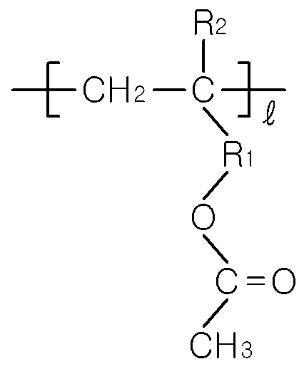
- the acetate group-containing monomer-derived repeating unit may be a repeating unit of Formula 1:
- R 1 is a single bond, straight or branched alkyl of 1 to 6 carbon atoms
- R 2 is hydrogen or methyl
- l is an integer between 1 and 100, respectively.
- the acrylic copolymer is a (meth) acrylate monomer and an acetate group-containing monomer, for example, vinyl acetate and / or allyl acetate in a molar ratio of 3: 7 to 7: 3, specifically 4: 6 to 6: 4 More specifically, by polymerization in a ratio of about 5: 5.
- the acrylic copolymer may include, for example, a butyl (meth) acrylate monomer, a methyl (meth) acrylate monomer, and a vinyl acetate and / or allyl acetate monomer, in a weight ratio of 3 to 5: 0.5 to 1.5: 4 to 6, specifically It may be prepared by a polymerization reaction of 4: 1: 5.
- the inorganic particles used in the present invention are not particularly limited and may be inorganic particles commonly used in the art.
- Non-limiting examples of the inorganic particles usable in the present invention include Al 2 O 3 , SiO 2 , B 2 O 3 , Ga 2 O 3 , TiO 2 , SnO 2 , and the like. These can be used individually or in mixture of 2 or more types.
- Al 2 O 3 (alumina) can be used as the inorganic particles used in the present invention.
- the size of the inorganic particles used in the present invention is not particularly limited, but the average particle diameter may be 1 nm to 2,000 nm, for example, 100 to 1,000 nm, 300 nm to 500 nm.
- the inorganic particles in the size range it is possible to prevent the dispersibility and coating processability of the inorganic particles in the coating liquid to be lowered and the thickness of the coating layer is appropriately adjusted to prevent the reduction of mechanical properties and increase of electrical resistance. Can be.
- the size of the pores generated in the separator is appropriately adjusted, there is an advantage that can lower the probability of the internal short circuit occurs during the charge and discharge of the battery.
- the inorganic particles may be used in the form of an inorganic dispersion in which it is dispersed in a suitable solvent.
- the appropriate solvent is not particularly limited and may be a solvent commonly used in the art.
- Acetone can be used as a suitable solvent for dispersing the inorganic particles, for example.
- the inorganic dispersion may be prepared by a conventional method without any particular limitation. For example, Al 2 O 3 may be added to acetone in an appropriate amount, and the inorganic dispersion may be milled and dispersed using a bead mill. Dispersions can be prepared.
- the inorganic particles in the coating layer may be included in 70 to 99% by weight, specifically 75 to 95% by weight, more specifically 80 to 90% by weight based on the total weight of the coating layer.
- the inorganic particles are contained within the above range, the heat dissipation characteristics of the inorganic particles may be sufficiently exhibited, and when the separator is coated using the inorganic particles, heat shrinkage of the separator may be effectively suppressed.
- Non-limiting examples of the solvent usable in the present invention include dimethyl formamide (DMF), dimethyl sulfoxide (DMSO), dimethylacetamide (DMAc), dimethyl carbonate (Dimethyl carbonate, DMC). ) Or N-methylpyrrolidone (N-Methyl pyrrolydone, NMP).
- the content of the solvent may be 20 to 99% by weight, specifically 50 to 95% by weight, and more specifically 70 to 95% by weight based on the weight of the coating composition. When the solvent is contained in the above range, the coating agent may be easily prepared, and the drying process of the coating layer may be performed smoothly.
- the coating layer and the coating composition according to the present embodiment is distinguished from the embodiment of the present invention in that another binder is added in addition to the acrylic copolymer.
- another binder is added in addition to the acrylic copolymer.
- binders added in addition to the acrylic copolymers include polyvinylidene fluoride (PVdF) homopolymers, polyvinylidene fluoride-Hexafluoropropylene copolymers (PVDF-HFP), and polymethyl Methacrylate (polymethylmethacrylate, PMMA), polyacrylonitrile (PAN), polyvinylpyrrolidone (PVP), polyvinylacetate (PVAc), polyethylene oxide (PEO), cellulose acetate (cellulose acetate, CA), cellulose acetate butyrate (CAB), cellulose acetate propionate (CAP), cyanoethylpullulan (CYEPL), cyanoethylpolyvinyl alcohol ( cyanoethylpolyvinylalcohol (CR-V), cyanoethylcellulose (CEC), Single or a mixture thereof selected from the group consisting of cynoethylsucrose, pullulan, carb
- the weight ratio of the acrylic copolymer and the added binder may be 9: 1 to 3: 7, specifically 9: 1 to 5: 5, and more specifically 8: 2 to 6: 4. Within this range, the shape stability may be further improved, and thus manufacturing of a battery having high efficiency charge and discharge characteristics may be possible.
- the PVdF-based binder when the PVdF-based binder is further included, the PVdF-based binder may have a weight average molecular weight (Mw) of 500,000 to 1,500,000 (g / mol).
- the PVdF-based binder may use, for example, PVdF-HFP or PVdF homopolymer.
- the PVdF-based binder may use a weight average molecular weight of 1,000,000 g / mol or more.
- one or more types of weight average molecular weights of 1,000,000 g / mol or less and one or more types of 1,000,000 g / mol or more can be mixed and used.
- the use of the PVdF-based binder within the above molecular weight range enhances the adhesion between the coating layer and the polyolefin-based substrate film, thereby effectively suppressing shrinkage of the polyolefin-based substrate film, which is weak to heat, and further improving the separation membrane with sufficient electrolyte impregnation. It can be manufactured and by using this has the advantage that can produce a battery with efficient electrical output.
- Membrane in accordance with embodiments of the present invention is to position the membrane between the anode and the cathode, when On the 100 °C 10 chogan pressure pressed into the 20kgf / cm 2 to 100kgf / cm 2 eseo 130 °C to stand for 10 minutes MD and TD
- Directional compression shrinkage may be less than 10% each. Specifically, it may be 5% or less, and more specifically 3% or less. Since the compression shrinkage rate is low, heat resistance and shrinkage of the separator are improved in an environment in which the separator is used, thereby improving the safety of the battery. That is, it is possible to provide a separation membrane having excellent shape stability.
- the method of measuring the compression shrinkage of the separator is as follows:
- Membrane samples were prepared in 50 mm x 50 mm lengths, and the positive and negative electrodes were cut into 55 mm x 55 mm, respectively, and the aluminum pouches used for cell production were cut into 6 cm x 6 cm. do.
- the anodes, separators, and cathodes are then placed in order and placed in half folded aluminum pouches.
- the sample is pressed at 100 ° C. for 10 seconds at a pressure of 20 kgf / cm 2 to 100 kgf / cm 2 , and then left at 130 ° C. for 10 minutes to obtain shrinkage.
- Separation membrane according to embodiments of the present invention may be less than 500 sec / 100cc, specifically 50 to 400 sec / 100cc, more specifically 50 to 300 sec / 100cc.
- the tensile strength in the MD direction of the separator according to the embodiments of the present invention may be 1750 kg / cm 2 or more, and the tensile strength in the TD direction may be 1650 kg / cm 2 or more, specifically 1700 kg / cm 2 or more.
- Separation membrane according to the embodiments of the present invention is excellent in mechanical properties without lowering the air permeability despite excellent compression shrinkage.
- Method for producing a separator according to an embodiment of the present invention is a repeating unit derived from the (meth) acrylate monomers on one or both sides of the polyolefin-based substrate film, and repeating units derived from an acetate group-containing monomer, such as vinyl acetate or allyl acetate monomer
- a binder comprising an acrylic copolymer having a; Inorganic particles; And forming a coating layer with a coating composition comprising a solvent.
- forming the coating composition may include mixing a binder, a solvent, and an inorganic particle including an acrylic copolymer and stirring at 10 to 40 ° C. for 30 minutes to 5 hours.
- the content of the solid content may be 10 to 20 parts by weight based on the coating composition, the weight ratio of the binder and the inorganic particles in the solid content may be 3: 7 to 0.1: 9.9.
- a coating composition may be prepared by preparing an inorganic dispersion in which the inorganic particles are dispersed in a dispersion medium, and mixing the mixture with a polymer solution containing a binder and a solvent including an acrylic copolymer.
- the inorganic dispersion is prepared separately as described above, the dispersibility and crude liquid stability of the inorganic particles and the binder may be improved.
- the binder component and the inorganic particles may each be prepared and mixed in a dissolved or dispersed state in a suitable solvent.
- an acrylic copolymer, a polyvinylidene fluoride homopolymer, and / or a polyvinylidene fluoride-hexafluoropropylene copolymer are prepared by dissolving each in an appropriate solvent, and an inorganic dispersion in which inorganic particles are dispersed.
- the coating composition can then be prepared by mixing them with a suitable solvent.
- a ball mill, a beads mill, a screw mixer, or the like may be used for the mixing.
- a coating layer is formed of the coating composition on one or both surfaces of the polyolefin-based substrate film.
- the method of coating the polyolefin-based substrate film using the coating agent is not particularly limited, and a method commonly used in the art may be used.
- Non-limiting examples of the coating method may include a dip coating method, a die coating method, a roll coating method, or a comma coating method. These may be applied alone or in combination of two or more methods.
- the coating layer of the separator of the present invention may be formed by, for example, a dip coating method.
- the coating layer may have a thickness of 0.01 ⁇ m to 20 ⁇ m, specifically 1 ⁇ m to 10 ⁇ m, and more specifically 1 ⁇ m to 5 ⁇ m. Within the thickness range, it is possible to form a coating layer having a suitable thickness to obtain excellent thermal stability and adhesion, and to prevent the thickness of the entire separator from being too thick to suppress the increase in the internal resistance of the battery.
- the coating layer may be dried by hot air, hot air, low humidity, vacuum drying, or a method of irradiating far infrared rays or electron beams.
- the drying temperature is different depending on the type of the solvent, but can be dried at a temperature of approximately 60 °C to 120 °C.
- the drying time also varies depending on the type of solvent, but may generally be dried for 1 minute to 1 hour. In embodiments, it may be dried for 1 minute to 30 minutes, or 1 minute to 10 minutes at a temperature of 90 °C to 120 °C.
- an electrochemical cell including a polyolefin-based porous separator including the coating layer and an anode and a cathode and filled with an electrolyte is provided.
- the kind of the electrochemical cell is not particularly limited, and may be a battery of a kind known in the art.
- the electrochemical cell of the present invention may be a lithium secondary battery such as a lithium metal secondary battery, a lithium ion secondary battery, a lithium polymer secondary battery or a lithium ion polymer secondary battery.
- a lithium secondary battery such as a lithium metal secondary battery, a lithium ion secondary battery, a lithium polymer secondary battery or a lithium ion polymer secondary battery.
- the method for producing the electrochemical cell of the present invention is not particularly limited, and a method commonly used in the art may be used.
- a non-limiting example of a method of manufacturing the electrochemical cell is as follows: A polyolefin-based separator comprising the coating layer of the present invention is placed between a positive electrode and a negative electrode of the battery, and then the battery is filled in such a manner as to fill an electrolyte solution. It can manufacture.
- the electrode constituting the electrochemical cell of the present invention can be produced in a form in which the electrode active material is bound to the electrode current collector by a method commonly used in the technical field of the present invention.
- the cathode active material is not particularly limited, and a cathode active material commonly used in the technical field of the present invention may be used.
- Non-limiting examples of the positive electrode active material include lithium manganese oxide, lithium cobalt oxide, lithium nickel oxide, lithium iron oxide or a lithium composite oxide in combination thereof.
- the negative electrode active material of the electrode active material used in one embodiment of the present invention is not particularly limited and may be a negative electrode active material commonly used in the technical field of the present invention.
- Non-limiting examples of the negative electrode active material include lithium adsorption materials such as lithium metal or lithium alloy, carbon, petroleum coke, activated carbon, graphite (graphite) or other carbons, and the like.
- the electrode current collector used in one embodiment of the present invention is not particularly limited, and an electrode current collector commonly used in the technical field of the present invention may be used.
- Non-limiting examples of the positive electrode current collector material of the electrode current collector may be a foil made of aluminum, nickel or a combination thereof.
- Non-limiting examples of the negative electrode current collector material of the electrode current collector may be a foil produced by copper, gold, nickel, copper alloy or a combination thereof.
- the electrolyte solution used in the present invention is not particularly limited and may be used an electrochemical cell electrolyte solution commonly used in the technical field of the present invention.
- the electrolyte solution may be one in which a salt having a structure such as A + B ⁇ is dissolved or dissociated in an organic solvent.
- a + include a cation consisting of an alkali metal cation such as Li + , Na + or K + , or a combination thereof.
- the B - Non-limiting examples of the, PF 6 -, BF 4 - , Cl -, Br -, I -, ClO 4 -, AsF 6 -, CH 3 CO 2 -, CF 3 SO 3 -, N (CF 3 SO 2) 2 - or C (CF 2 SO 2) 3 - anions, such as, or may be an anion consisting of a combination thereof.
- Non-limiting examples of the organic solvent include propylene carbonate (PC), ethylene carbonate (EC), diethyl carbonate (DEC), dimethyl carbonate (DMC), dipropyl carbonate (Dipropyl carbonate, DPC), dimethyl sulfoxide (DMSO), acetonitrile, dimethoxyethane, diethoxyethane, tetrahydrofuran (Tetrahydrofuran, THF), N-methyl- 2-pyrrolidone (N-methyl-2-pyrrolidone, NMP), ethyl methyl carbonate (EMC), gamma-butyrolactone ( ⁇ -Butyrolactone, GBL), etc. are mentioned. These may be used alone or in combination of two or more thereof.
- PC propylene carbonate
- EC ethylene carbonate
- DEC diethyl carbonate
- DMC dimethyl carbonate
- Dipropyl carbonate Dipropyl carbonate
- DMSO dimethyl sulfoxide
- Acetone is an acrylic copolymer binder in which butyl methacrylate (BMA), methyl methacrylate (MMA), and vinyl acetate (Vinyl Acetate, VAc) are polymerized at a 4/1/5 molar ratio.
- BMA butyl methacrylate
- MMA methyl methacrylate
- VAc vinyl acetate
- Alumina dispersion was prepared by adding alumina (LS235, Nippon Light Metal) to acetone at 25% by weight and dispersing the beads for 3 hours.
- the first and second binder solutions and the alumina dispersion were mixed so that the weight ratio of the binder solid content and the alumina solid content was 1/6 so that the weight ratio of the acrylic binder and the PVdF binder was 7/3, and the total solid content was 10 weight.
- Acetone was added to make the coating solution.
- 12 ⁇ m thick polyethylene fabric (SK, Inc.) was coated on both sides of the coating solution with a thickness of 2 ⁇ m, respectively, to prepare a coating separator having a total thickness of about 16 ⁇ m.
- the binder solution and the alumina dispersion were mixed so that the weight ratio of the binder solid content and the alumina solid content was 1/5 such that the weight ratio of the acrylic binder and the KF9300, 21216 binder was 5/3/2, and the total solid content was 10% by weight.
- Acetone was added to prepare a coating solution.
- a coating separator of about 16 ⁇ m in total thickness was prepared by coating 2 ⁇ m thick with the coating solution on both sides of a 12 ⁇ m thick polyethylene fabric (SK).
- Example 1 except that butyl methacrylate (BMA), methyl methacrylate (MMA) and allyl acetate (Allyl Acetate) as the acrylic binder was used in a molar ratio of 4/1/5. In the same manner as in the production of a coating separator having a total thickness of about 16 ⁇ m.
- BMA butyl methacrylate
- MMA methyl methacrylate
- Allyl Acetate allyl acetate
- Example 1 except that the molar ratio of butyl methacrylate (BMA), acrylonitrile (AN), and vinyl acetate 4/1/5 was used as the acrylic binder in the same manner as in Example 1 A coating separator having a total thickness of about 16 ⁇ m was prepared.
- BMA butyl methacrylate
- AN acrylonitrile
- vinyl acetate 4/1/5 vinyl acetate 4/1/5
- a separator was manufactured in the same manner as in Example 1, except that the weight ratio of the binder solids to the alumina solids was 1/6 by using only the acrylic copolymer binder without using the PVdF-based binder.
- Alumina dispersion was prepared by adding alumina (LS235, Nippon Light Metal) to acetone at 25% by weight and dispersing the beads for 3 hours. The binder solution and the alumina dispersion were mixed so that the weight ratio of the binder solid content and the alumina solid content was 1/6 so that the weight ratio of the KF9300 and 21216 binders was 5/5, and acetone was added so that the total solid content was 11% by weight.
- a coating solution was prepared.
- a coating separator having a total thickness of about 16 ⁇ m was prepared using a coating solution of polyethylene fabric (SK) having a thickness of 12 ⁇ m.
- Example 1 except that polybutyl methacrylate (PBMA) was used as the acrylic binder was carried out in the same manner as in Example 1 to prepare a coating separator having a total thickness of about 16 ⁇ m.
- PBMA polybutyl methacrylate
- Comparative Example 3 a polyethylene fabric (SK company) having a thickness of 12 um which was the same as that used in Comparative Example 1 was used without coating.
- Each of the separators prepared in the above Examples and Comparative Examples was prepared to cut 10 samples cut at 10 different points to a size of 1 inch (1 inch) in diameter, and then the air permeability measuring device (Asahi Seiko) G) was used to measure the time for passage of 100 cc of air in each sample. The time was measured five times each, and then the average value was calculated as air permeability.
- Each of the separators prepared in Examples and Comparative Examples was cut into five pieces in a rectangular shape of 50 mm long by 150 mm long by 150 mm long by MD, and 150 mm long by 50 mm wide by 50 mm TD.
- Ten samples were prepared, and each sample was mounted on a UTM (tension tester) to bite to a measurement length of 20 mm, and then the sample was pulled to measure average tensile strength in the MD and TD directions.
- Each of the separators prepared in Examples and Comparative Examples was 50 mm long by 50 mm long by TD.
- the aluminum pouches used for battery production are cut into 6 cm x 6 cm and prepared.
- the anodes, separators, and cathodes are then placed in order and placed in half folded aluminum pouches.
- the compression shrinkage is indicated by 5 points at regular intervals on the membrane, pressurized at 20 kgf / cm 2 for 10 seconds at 100 ° C., left at 130 ° C. for 10 minutes, and then measured by the contracted length between the gaps. The compression shrinkage was obtained.
- the non-compression shrinkage was measured for 10 minutes after leaving the membrane sample in an oven at 130 °C to measure the shrinkage of the membrane.
Landscapes
- Chemical & Material Sciences (AREA)
- Chemical Kinetics & Catalysis (AREA)
- Electrochemistry (AREA)
- General Chemical & Material Sciences (AREA)
- Inorganic Chemistry (AREA)
- Engineering & Computer Science (AREA)
- Composite Materials (AREA)
- Materials Engineering (AREA)
- Manufacturing & Machinery (AREA)
- Cell Separators (AREA)
Abstract
본 발명은, 폴리올레핀계 기재 필름, 및 상기 기재 필름의 일면 혹은 양면에 형성된, 유기 바인더 및 무기입자를 포함하는 코팅층을 포함하고, 상기 유기 바인더는 (메트)아크릴레이트 단량체 유래 반복단위, 및 아세테이트기 함유 단량체 유래 반복단위를 갖는 아크릴계 공중합체를 포함하는 분리막, 분리막 코팅제 조성물 및 상기 분리막을 포함하는 전기 화학 전지에 관한 것이다.
Description
본 발명은 분리막 코팅제 조성물에 관한 것이다. 또한, 본 발명은 상기 코팅제 조성물로 코팅 처리된 분리막 및 이를 이용한 전기 화학 전지에 관한 것이다.
전기 화학 전지용 분리막(separator)은 전지 내에서 양극과 음극을 서로 격리시키면서 이온 전도도를 지속적으로 유지시켜 주어 전지의 충전과 방전이 가능하게 하는 중간막을 의미한다.
최근 전지의 안정성이 대두됨에 따라, 이러한 특성과 관련하여 양극간의 단락을 방지하는 분리막의 역할이 중요하게 다루어지고 있다. 일반적으로 사용되는 폴리올레핀 계열 원단의 경우 고온에서 열수축이 심하고 물리적으로 내구성이 약하다. 따라서 전지에 이상이 발생하여 내부의 온도가 상승하게 되면, 분리막의 변형이 일어나기 쉽고 심각할 경우 폭발이 발생할 수 있다. 따라서 고온 안정성과 관련된 내열도 및 내수축성의 향상은 분리막 개발에 중요한 요소이다. 분리막의 내열성 개선과 관련하여 내열성 고분자를 섬유상으로 가공하여 제조하는 부직포 분리막, 적은 양의 바인더를 사용하여 무기물 입자를 연결하여 만드는 세라믹 분리막, 기존의 폴리올레핀 또는 부직포 원단에 세라믹과 바인더를 코팅하는 코팅 분리막(대한민국 등록특허 제10-0775310호) 등의 개발이 진행되고 있다. 최근에는 분리막 두께 제한으로 인하여 코팅층의 두께에 대한 한계가 있기 때문에, 보다 얇은 코팅층을 통해 물성을 확보하기 위한 연구가 진행되고 있다.
본 발명은 전지 내에서의 수축이 방지되고 내열성 및 형태안정성이 증진된 코팅 분리막을 제공하고자 한다.
본 발명의 일 예에 따르면, (메트)아크릴레이트계((meth)acrylate) 단량체 유래 반복단위, 및 아세테이트기 함유 단량체 유래 반복단위를 포함하는 아크릴계 공중합체를 포함하는 유기 바인더; 무기 입자; 및 용매를 포함하는 분리막 코팅제 조성물이 제공된다.
본 발명의 다른 예에 따르면, 폴리올레핀계 기재 필름, 및 상기 기재 필름의 일면 혹은 양면에 형성된, 유기 바인더 및 무기입자를 포함하는 코팅층을 포함하고, 상기 유기 바인더는 (메트)아크릴레이트계 단량체 유래 반복단위 및 아세테이트기 함유 단량체 유래 반복단위를 포함하는 아크릴계 공중합체를 포함하는, 분리막이 제공된다.
본 발명의 다른 일 예에 따르면, 폴리올레핀계 기재 필름, 및 상기 기재 필름의 일면 혹은 양면에 형성된, 유기 바인더 및 무기입자를 포함하는 코팅층을 포함하는 분리막을, 양극 및 음극 사이에 위치시키고 100℃에서 10초간 20kgf/cm2 내지 100kgf/cm2의 압력으로 압착한 후 130℃에서 10분간 방치시 MD 및 TD 방향의 압착 수축률이 각각 10%이하인 분리막이 제공된다.
본 발명의 다른 일 예에 따르면, 상기 일 예에 따른 분리막을 포함하는 전기 화학 전지, 특히 리튬 이차 전지가 제공된다.
본 발명에 따른 분리막은 전지 내에서의 수축이 방지되고 내열성이 증진된 효과가 있다. 또한, 본 발명에 따른 분리막은 추가로 통기도 및 기계적 강도 등의 물성이 우수하다.
이하 본 발명에 대해 보다 상세히 설명한다. 본원 명세서에 기재되어 있지 않은 내용은 본 발명의 기술 분야 또는 유사 분야에서 숙련된 자이면 충분히 인식하고 유추할 수 있는 것이므로 그 설명을 생략한다.
본 발명의 일 실시예에 따른 분리막은 기재 필름, 및 상기 기재 필름의 일면 혹은 양면에 형성된 코팅층을 포함한다.
상기 기재 필름은 폴리올레핀계일 수 있다. 폴리올레핀계 기재 필름은 셧 다운(shut down) 기능이 우수하여 전지의 안전성 향상에 기여할 수 있다. 폴리올레핀계 기재 필름은 예를 들어 폴리에틸렌 단일막, 폴리프로필렌 단일막, 폴리에틸렌/폴리프로필렌 이중막, 폴리프로필렌/폴리에틸렌/폴리프로필렌 삼중막 및 폴리에틸렌/폴리프로필렌/폴리에틸렌 삼중막으로 이루어진 군에서 선택될 수 있다. 상기 폴리올레핀계 기재 필름의 두께는 1 내지 40 ㎛일 수 있고, 구체적으로는 5 ㎛ 내지 15 ㎛ 일 수 있다. 상기 두께 범위 내의 기재 필름을 사용하는 경우, 전지의 양극과 음극의 단락을 방지할 수 있을 만큼 충분히 두꺼우면서도 전지의 내부 저항을 증가시킬 만큼 두껍지는 않은, 적절한 두께를 갖는 분리막을 제조할 수 있다.
상기 코팅층은 코팅제 조성물로 형성될 수 있으며, 코팅제 조성물은 유기 바인더, 무기입자, 및 용매를 포함할 수 있다.
구체적으로, 상기 유기 바인더는 아크릴계 공중합체일 수 있으며, 예를 들어 (메트)아크릴레이트계 단량체 유래 반복단위, 및 아세테이트기 함유 단량체 유래 반복단위를 포함하는 아크릴계 공중합체일 수 있다. 바인더로 (메트)아크릴레이트계 단량체 유래 반복단위, 및 아세테이트기 함유 단량체 유래 반복단위를 갖는 아크릴계 공중합체를 사용하면 분리막이 실제 사용되는 환경인 전지 내에서 분리막의 수축을 방지하고 내열성을 증진시킬 수 있다. 통상 분리막의 내열도는 분리막 자체에 대해 일정한 조건에서 열을 가하고 가열 전후 분리막의 길이 방향(이하, 이를 'MD 방향'이라 한다) 및 폭 방향(이하, 이를 'TD 방향'이라 한다) 각각에서의 수축 정도로 평가된다. 그러나, 상기와 같이 평가하는 내열도는 실제 분리막이 사용되는 환경에서의 열 수축 안정성을 제대로 반영하지 못하며, 전지 내에서의 분리막의 실제 형태 안정성과 일치하지 않는다. 따라서, 전지 내에서의 전극 사이에 분리막을 배치하고 압착된 상태에서의 내열도 및 수축률을 평가할 필요가 있다. (메트)아크릴레이트계 단량체 유래 반복단위, 및 아세테이트기 함유 단량체 유래 반복단위를 포함하는 아크릴계 공중합체를 바인더로 사용하면 상기 아크릴계 공중합체가 전극과 분리막의 접착력을 향상시키고, 이러한 접착력이 내열도를 증진시키고 분리막의 수축을 방지하는 효과가 있다. 즉, 전지 내에서 분리막의 형태안정성이 개선되고 이에 따른 전지의 안전성이 향상된다.
상기 아크릴계 공중합체의 유리전이온도(Tg)는 100℃ 미만, 예를 들어, 20 내지 60℃일 수 있다. 상기 범위이면 분리막을 전극 사이에 위치시키고 이를 압착하는 온도에서 양호한 접착을 형성하여 수축률 개선 및 내열도 증진에 유리할 수 있다.
본원에서 사용될 수 있는 (메트)아크릴레이트계 단량체 유래 반복단위, 및 아세테이트기 함유 단량체 유래 반복단위를 갖는 아크릴계 공중합체는 상기와 같이 양극과 음극 사이에서 압착하는 온도에서 양호한 접착력을 형성할 수 있는 것이라면 특별히 제한되지 않으나, 예를 들어, 상기 아크릴계 공중합체는 부틸 (메트)아크릴레이트, 프로필 (메트)아크릴레이트, 에틸 (메트)아크릴레이트 및 메틸 (메트)아크릴레이트로 이루어진 군으로부터 선택된 1종 이상의 (메트)아크릴레이트계 단량체와, 비닐 아세테이트 및 알릴 아세테이트로 이루어진 군으로부터 선택된 1종 이상의 아세테이트기 함유 단량체를 중합시켜 생성된 공중합체일 수 있다.
상기 아세테이트기 함유 단량체 유래 반복단위는 화학식 1의 반복단위일 수 있다:
[화학식 1]
상기 화학식 1에서,
R1은 단일 결합이거나, 직쇄 또는 분지된 탄소수 1 내지 6의 알킬이고, R2는 수소이거나 메틸이고, l은 각각 1 내지 100 사이의 정수이다.
상기 아크릴계 공중합체는 상기 (메트)아크릴레이트계 단량체와, 아세테이트기 함유 단량체, 예를 들어, 비닐 아세테이트 및/또는 알릴 아세테이트를 몰비 3:7 내지 7:3, 구체적으로 4:6 내지 6:4, 보다 구체적으로는 약 5:5의 비로 중합하여 제조될 수 있다. 상기 아크릴계 공중합체는 예를 들어, 부틸 (메트)아크릴레이트 단량체, 메틸 (메트)아크릴레이트 단량체, 및 비닐 아세테이트 및/또는 알릴 아세테이트 단량체를, 중량비 3 내지 5 : 0.5 내지 1.5 : 4 내지 6, 구체적으로, 4 : 1 : 5로 중합 반응시켜 제조될 수 있다.
본 발명에서 사용되는 무기 입자는 특별히 제한되지 아니하며 당해 기술 분야에서 통상적으로 사용하는 무기 입자를 사용할 수 있다. 본 발명에서 사용 가능한 무기 입자의 비제한적인 예로는 Al2O3, SiO2, B2O3, Ga2O3, TiO2 또는 SnO2 등을 들 수 있다. 이들은 단독 또는 2종 이상을 혼합하여 사용할 수 있다. 본 발명에서 사용되는 무기 입자로는 예를 들어, Al2O3(알루미나)를 사용할 수 있다.
본 발명에서 사용되는 무기 입자의 크기는 특별히 제한되지 아니하나, 평균 입경이 1 nm 내지 2,000 nm일 수 있고, 예를 들어, 100 내지 1,000 nm, 300 nm 내지 500 nm일 수 있다. 상기 크기 범위의 무기 입자를 사용하는 경우, 코팅액 내에서의 무기 입자의 분산성 및 코팅 공정성이 저하되는 것을 방지할 수 있고 코팅층의 두께가 적절히 조절되어 기계적 물성의 저하 및 전기적 저항의 증가를 방지할 수 있다. 또한, 분리막에 생성되는 기공의 크기가 적절히 조절되어 전지의 충방전 시 내부 단락이 일어날 확률을 낮출 수 있는 이점이 있다.
코팅제 조성물의 제조에 있어서 상기 무기 입자는 이를 적절한 용매에 분산시킨 무기 분산액 형태로 이용될 수 있다. 상기 적절한 용매는 특별히 제한되지 아니하며 당해 기술 분야에서 통상적으로 사용하는 용매를 사용할 수 있다. 상기 무기 입자를 분산시키는 적절한 용매로서 예를 들어, 아세톤을 사용할 수 있다. 상기 무기 분산액을 제조하는 방법은 특별한 제한없이 통상적인 방법에 의할 수 있으며, 예를 들어 Al2O3를 아세톤에 적정 함량으로 첨가하고 비즈 밀(Beads mill)을 이용해 밀링하여 분산시키는 방식으로 무기 분산액을 제조할 수 있다.
코팅층 내에서 상기 무기입자는 코팅층 전체 중량을 기준으로 70 내지 99 중량%, 구체적으로 75 내지 95중량%, 보다 구체적으로 80 내지 90중량%로 포함될 수 있다. 상기 범위 내로 무기 입자를 함유하는 경우, 무기 입자의 방열 특성이 충분히 발휘될 수 있으며 이를 이용하여 분리막을 코팅할 경우 분리막의 열수축을 효과적으로 억제할 수 있다.
본 발명에서 사용 가능한 상기 용매의 비제한적인 예로는 디메틸포름아미드 (Dimethyl formamide, DMF), 디메틸설폭사이드 (Dimethyl sulfoxide, DMSO), 디메틸아세트아미드 (Dimethyl acetamide, DMAc), 디메틸카보네이트 (Dimethyl carbonate, DMC) 또는 N-메틸피롤리돈 (N-Methyl pyrrolydone, NMP) 등을 들 수 있다. 코팅제 조성물의 중량을 기준으로 용매의 함량은 20 내지 99 중량%일 수 있고, 구체적으로 50 내지 95 중량%일 수 있으며, 보다 구체적으로 70 내지 95 중량%일 수 있다. 상기 범위의 용매를 함유하는 경우 코팅제의 제조가 용이해지며 코팅층의 건조 공정이 원활히 수행될 수 있다.
이하, 본 발명의 다른 실시예에 따른 분리막 및 코팅제 조성물에 대해 설명한다. 본 실시예에 따른 코팅층 및 코팅제 조성물은 상기 아크릴계 공중합체 외에 다른 바인더를 추가한다는 점에서 상기 본 발명의 일 실시예와 구분된다. 아크릴계 공중합체외에 다른 바인더를 추가로 포함함으로써 접착력 및 내열성을 더욱 향상시킬 수 있다. 이에 이하에서는 추가되는 다른 바인더를 중심으로 설명한다.
아크릴계 공중합체 외에 추가되는 바인더의 예로, 폴리비닐리덴 플루오라이드(Polyvinylidene fluoride, PVdF) 호모폴리머, 폴리비닐리덴 플루오라이드-헥사플루오로프로필렌 코폴리머 (Polyvinylidene fluoride-Hexafluoropropylene copolymer, PVdF-HFP), 폴리메틸메타크릴레이트(polymethylmethacrylate, PMMA), 폴리아크릴로니트릴 (polyacrylonitrile, PAN), 폴리비닐피롤리돈(polyvinylpyrrolidone, PVP), 폴리비닐아세테이트(polyvinylacetate, PVAc), 폴리에틸렌옥사이드(polyethylene oxide, PEO), 셀룰로오스 아세테이트 (cellulose acetate, CA), 셀룰로오스 아세테이트 부틸레이트(cellulose acetate butyrate, CAB), 셀룰로오스 아세테이트 프로피오네이트 (cellulose acetate propionate, CAP), 시아노에틸풀루란 (cyanoethylpullulan, CYEPL), 시아노에틸폴리비닐알콜 (cyanoethylpolyvinylalcohol, CR-V), 시아노에틸셀룰로오스 (cyanoethylcellulose, CEC), 시아노에틸수크로오스 (cyanoethylsucrose), 풀루란 (pullulan), 카르복실 메틸 셀룰로오스 (carboxyl methyl cellulose, CMC), 및 아크릴로니트릴스티렌부타디엔 공중합체 (acrylonitrilestyrene-butadiene copolymer)로 이루어진 군으로부터 선택된 단독 또는 이들의 혼합물을 들 수 있다. 아크릴계 공중합체 및 상기 추가되는 바인더의 중량비는 9:1 내지 3:7으로, 구체적으로 9:1 내지 5:5로, 보다 구체적으로는 8:2 내지 6:4일 수 있다. 상기 범위이면 형태 안정성이 더욱 개선되어 고효율의 충방전 특성을 갖는 전지의 제조가 가능할 수 있다. 예를 들어 PVdF계 바인더를 추가로 포함하는 경우, PVdF계 바인더는 중량평균분자량(Mw)이 500,000 내지 1,500,000 (g/mol) 일 수 있다. 또한, PVdF계 바인더는 예를 들어 PVdF-HFP 또는 PVdF 호모폴리머를 사용할 수 있다. 또한, PVdF계 바인더는 중량평균분자량이 1,000,000 g/mol 이상인 것을 사용할 수도 있다. 또한, 중량평균분자량이 상이한 2종 이상을 혼합하여 사용할 수도 있다. 예를 들어, 중량평균분자량이 1,000,000 g/mol 이하인 1종 이상과 1,000,000 g/mol 이상인 1종 이상을 혼합하여 사용할 수 있다. 상기 분자량 범위 내의 PVdF계 바인더를 사용하면 코팅층과 폴리올레핀계 기재 필름 사이의 접착력이 강화되어, 열에 약한 폴리올레핀계 기재 필름이 열에 의해 수축되는 것을 효과적으로 억제할 수 있으며, 또한 전해질 함침성이 충분히 향상된 분리막을 제조할 수 있으며 이를 활용하여 전기 출력이 효율적으로 일어나는 전지를 생산할 수 있는 이점이 있다.
본 발명의 실시예들에 따른 분리막은 양극과 음극 사이에 분리막을 위치시키고, 100℃에서 10초간 20kgf/cm2 내지 100kgf/cm2의 압력으로 압착한 후 130℃에서 10분간 방치시 MD 및 TD 방향 압착 수축률이 각각 10%이하일 수 있다. 구체적으로 5% 이하, 보다 구체적으로 3% 이하일 수 있다. 압착 수축률이 낮으므로 분리막이 사용되는 전지 내 환경에서 분리막의 내열성 및 수축성이 개선되어 전지의 안전성을 향상시키는 이점이 있다. 즉, 형태안정성이 우수한 분리막을 제공할 수 있다.
상기 분리막의 압착 수축률을 측정하는 방법은 다음과 같다:
분리막 샘플을 가로(MD) 50 mm ×세로(TD) 50 mm로 준비하고, 양극과 음극을 각각 55 mm ×55 mm로 잘라 준비하고, 또한 전지 제작에 사용되는 알루미늄 파우치를 6cm×6cm로 잘라 준비한다. 양극, 분리막, 및 음극 순서로 차례로 올려 반으로 접은 알루미늄 파우치에 집어넣는다. 상기 샘플을 100℃에서 10초간 20kgf/cm2 내지 100kgf/cm2의 압력으로 압착한 후 130℃에서 10분간 방치 후 수축률을 구한다.
본 발명의 실시예들에 따른 분리막은 통기도가 500 sec/100cc 이하, 구체적으로 50 내지 400 sec/100cc, 보다 구체적으로 50 내지 300 sec/100cc 일 수 있다. 본 발명의 실시예들에 따른 분리막의 MD 방향의 인장강도가 1750 kg/cm2 이상이고, TD 방향의 인장강도가 1650 kg/cm2 이상, 구체적으로 1700 kg/cm2 이상일 수 있다.
본 발명의 실시예들에 따른 분리막은 압착 수축률이 우수함에도 통기도가 저하되지 않고 기계적 물성까지 우수하다.
이하, 본 발명의 일 실시예에 따른 분리막의 제조방법에 대해 설명한다. 본 발명의 일 실시예에 따른 분리막의 제조 방법은 폴리올레핀계 기재 필름의 일면 또는 양면에 (메트)아크릴레이트계 단량체 유래 반복단위, 및 비닐 아세테이트 또는 알릴 아세테이트 단량체와 같은, 아세테이트기 함유 단량체 유래 반복단위를 갖는 아크릴계 공중합체를 포함하는 바인더; 무기 입자; 및 용매를 포함하는 코팅제 조성물로 코팅층을 형성하는 것을 포함한다.
우선, 상기 코팅제 조성물을 형성하는 것은 아크릴계 공중합체를 포함하는 바인더, 용매, 및 무기 입자를 혼합하고 10 내지 40℃에서 30분 내지 5시간 동안 교반하는 것을 포함할 수 있다. 이 때, 고형분의 함량은 코팅 조성물에 대해 10 내지 20 중량부일 수 있으며, 고형분에서 바인더와 무기입자의 중량비는 3:7 내지 0.1:9.9일 수 있다.
또는, 상기 무기 입자를 분산 매질에 분산시킨 무기 분산액을 제조하고, 이를 아크릴계 공중합체를 포함하는 바인더 및 용매를 함유하는 고분자 용액과 혼합하여 코팅제 조성물을 제조할 수 있다. 상기와 같이 무기 분산액을 별도로 제조하는 경우 무기입자 및 바인더의 분산성 및 조액 안정성을 향상시킬 수 있다. 따라서, 다른 양태에서, 본 발명의 코팅제 조성물을 제조함에 있어서, 바인더 성분 및 무기 입자는 각각 적절한 용매 내에 용해 또는 분산된 상태로 제조되어 혼합될 수 있다.
예를 들어, 아크릴계 공중합체와 폴리비닐리덴 플루오라이드 호모폴리머 및/또는 폴리비닐리덴 플루오라이드-헥사플루오로프로필렌 코폴리머 각각을 적절한 용매에 용해시킨 용액과, 무기 입자를 분산시킨 무기 분산액을 각각 제조한 다음, 이들을 적절한 용매와 함께 혼합하는 방식으로 코팅제 조성물을 제조할 수 있다. 상기 혼합에는 볼 밀(Ball mill), 비즈 밀(Beads mill) 또는 스크류 믹서(Screw mixer) 등을 이용할 수 있다.
이어서, 폴리올레핀계 기재 필름의 일면 또는 양면에 상기 코팅제 조성물로 코팅층을 형성한다.
상기 코팅제를 이용하여 폴리올레핀계 기재 필름을 코팅하는 방법은 특별히 제한되지 아니하며, 본 발명의 기술 분야에서 통상적으로 사용하는 방법을 사용할 수 있다. 상기 코팅 방법의 비제한적인 예로는, 딥(Dip) 코팅법, 다이(Die) 코팅법, 롤(Roll) 코팅법 또는 콤마(Comma) 코팅법 등을 들 수 있다. 이들은 단독 또는 2 가지 이상의 방법을 혼합하여 적용될 수 있다. 본 발명의 분리막의 코팅층은 예를 들어 딥 코팅법에 의해 형성된 것일 수 있다.
본 실시예의 코팅층의 두께는 0.01 ㎛ 내지 20 ㎛일 수 있으며, 구체적으로 1 ㎛ 내지 10 ㎛, 보다 구체적으로 1 ㎛ 내지 5 ㎛일 수 있다. 상기 두께 범위 내에서, 적절한 두께의 코팅층을 형성하여 우수한 열적 안정성 및 접착력을 얻을 수 있으며, 전체 분리막의 두께가 지나치게 두꺼워지는 것을 방지하여 전지의 내부 저항이 증가하는 것을 억제할 수 있다.
본 발명에서 코팅층을 건조하는 것은 온풍, 열풍, 저습풍에 의한 건조나 진공 건조 또는 원적외선이나 전자선 등을 조사하는 방법을 사용할 수 있다. 그리고 건조 온도는 용매의 종류에 따라 차이가 있으나 대체로 60℃ 내지 120℃의 온도에서 건조할 수 있다. 건조 시간 역시 용매의 종류에 따라 차이가 있으나 대체로 1분 내지 1시간 건조할 수 있다. 구체예에서, 90℃ 내지 120 ℃의 온도에서 1분 내지 30분, 또는 1분 내지 10분 건조할 수 있다.
본 발명의 또 다른 일 양태에 따르면, 상기 코팅층을 포함하는 폴리올레핀계 다공성 분리막 및 양극, 음극을 포함하며 전해질로 채워진 전기 화학 전지를 제공한다.
상기 전기 화학 전지의 종류는 특별히 제한되지 아니하며, 본 발명의 기술 분야에서 알려진 종류의 전지일 수 있다.
본 발명의 상기 전기 화학 전지는 구체적으로는 리튬 금속 이차 전지, 리튬 이온 이차 전지, 리튬 폴리머 이차 전지 또는 리튬 이온 폴리머 이차 전지 등과 같은 리튬 이차 전지일 수 있다.
본 발명의 전기 화학 전지를 제조하는 방법은 특별히 제한되지 아니하며, 본 발명의 기술 분야에서 통상적으로 사용하는 방법을 사용할 수 있다.
상기 전기 화학 전지를 제조하는 방법의 비제한적인 예는 다음과 같다: 본 발명의 상기 코팅층을 포함하는 폴리올레핀계 분리막을, 전지의 양극과 음극 사이에 위치시킨 후, 이에 전해액을 채우는 방식으로 전지를 제조할 수 있다.
본 발명의 전기 화학 전지를 구성하는 전극은, 본 발명의 기술 분야에서 통상적으로 사용하는 방법에 의해 전극 활물질을 전극 전류집전체에 결착된 형태로 제조할 수 있다.
본 발명의 일 실시예에서 사용되는 상기 전극 활물질 중 양극 활물질은 특별히 제한되지 아니하며, 본 발명의 기술 분야에서 통상적으로 사용하는 양극 활물질을 사용할 수 있다. 상기 양극 활물질의 비제한적인 예로는, 리튬 망간 산화물, 리튬 코발트 산화물, 리튬 니켈 산화물, 리튬 철 산화물 또는 이들을 조합한 리튬 복합 산화물 등을 들 수 있다.
본 발명의 일 실시예에서 사용되는 상기 전극 활물질 중 음극 활물질은 특별히 제한되지 아니하며, 본 발명의 기술 분야에서 통상적으로 사용하는 음극 활물질을 사용할 수 있다.
상기 음극 활물질의 비제한적인 예로는, 리튬 금속 또는 리튬 합금, 탄소, 석유 코크 (petroleum coke), 활성화 탄소 (activated carbon), 그라파이트 (graphite) 또는 기타 탄소류 등과 같은 리튬 흡착 물질 등을 들 수 있다. 본 발명의 일 실시예에서 사용되는 상기 전극 전류집전체는 특별히 제한되지 아니하며, 본 발명의 기술 분야에서 통상적으로 사용하는 전극 전류집전체를 사용할 수 있다.
상기 전극 전류집전체 중 양극 전류집전체 소재의 비제한적인 예로는, 알루미늄, 니켈 또는 이들의 조합에 의하여 제조되는 호일 등을 들 수 있다. 상기 전극 전류집전체 중 음극 전류집전체 소재의 비제한적인 예로는, 구리, 금, 니켈, 구리 합금 또는 이들의 조합에 의하여 제조되는 호일 등을 들 수 있다.
본 발명에서 사용되는 전해액은 특별히 제한되지 아니하며, 본 발명의 기술 분야에서 통상적으로 사용하는 전기 화학 전지용 전해액을 사용할 수 있다.
상기 전해액은 A+ B-와 같은 구조의 염이, 유기 용매에 용해 또는 해리된 것일 수 있다. 상기 A+의 비제한적인 예로는, Li+, Na+ 또는 K+와 같은 알칼리 금속 양이온, 또는 이들의 조합으로 이루어진 양이온을 들 수 있다. 상기 B-의 비제한적인 예로는, PF6
-, BF4
-, Cl-, Br-, I-, ClO4
-, AsF6
-, CH3CO2
-, CF3SO3
-, N (CF3SO2)2
- 또는 C (CF2SO2)3
-와 같은 음이온, 또는 이들의 조합으로 이루어진 음이온을 들 수 있다. 상기 유기 용매의 비제한적인 예로는, 프로필렌 카보네이트 (Propylene carbonate; PC), 에틸렌 카보네이트 (Ethylene carbonate, EC), 디에틸카보네이트 (Diethyl carbonate; DEC), 디메틸카보네이트 (Dimethyl carbonate, DMC), 디프로필카보네이트 (Dipropyl carbonate, DPC), 디메틸설폭사이드 (Dimethyl sulfoxide, DMSO), 아세토니트릴 (Acetonitrile), 디메톡시에탄 (Dimethoxyethane), 디에톡시에탄 (Diethoxyethane), 테트라하이드로푸란 (Tetrahydrofuran, THF), N-메틸-2-피롤리돈 (N-methyl-2-pyrrolidone, NMP), 에틸메틸카보네이트 (Ethyl methyl carbonate, EMC) 또는 감마-부티로락톤 (γ-Butyrolactone, GBL) 등을 들 수 있다. 이들은 단독으로 사용되거나 2 종 이상을 혼합하여 사용될 수 있다.
이하, 실시예, 비교예 및 실험예를 기술함으로써 본 발명을 보다 상세히 설명한다. 다만, 하기의 실시예, 비교예 및 실험예는 본 발명의 일 예시에 불과하며 본 발명의 내용이 이에 한정되는 것으로 해석되어서는 아니된다.
실시예
실시예 1: 코팅 분리막의 제조
부틸 메타아크릴레이트(Buthyl Methacrylate, BMA), 메틸 메타크릴레이트(Methyl Methacrylate, MMA), 비닐 아세테이트(Vinyl Acetate, VAc) 가 4/1/5 몰비율로 중합된 아크릴계 공중합체 바인더를 아세톤(acetone)에 용해시켜 고형분 5 중량% 인 제1 바인더 용액과, PVdF계 바인더 KF9300 (쿠레하사, Mw: 1,200,000 g/mol)을 아세톤, DMAc 혼합 용매에 용해시켜 고형분 7 중량% 용액인 제2 바인더 용액을 각각 제조하였다. 알루미나 (LS235, 일본경금속)를 아세톤에 25 중량%로 첨가 후 3시간 동안 비즈밀 분산을 하여 알루미나 분산액을 제조하였다. 위의 아크릴계 바인더와 PVdF계 바인더의 중량비가 7/3이 되도록, 바인더 고형분과 알루미나 고형분의 중량비가 1/6 비율이 되도록 제1, 제2 바인더 용액 및 알루미나 분산액을 혼합하였으며, 전체 고형분이 10 중량%가 되도록 아세톤을 첨가하여 코팅액을 제조하였다. 두께가 12 ㎛인 폴리에틸렌 원단(SK社)의 양면에 상기 코팅액으로 각각 2㎛ 두께로 코팅하여 총 두께 16 ㎛정도의 코팅 분리막을 제작하였다.
실시예 2: 코팅 분리막의 제조
부틸 메타크릴레이트(BMA), 메틸 메타크릴레이트(MMA), 비닐 아세테이트(VAc)가 4/1/5 몰비율로 중합된 아크릴계 바인더를 아세톤에 용해시킨 5 중량% 용액과, PVdF계 바인더 KF9300을 아세톤, DMAc 혼합 용매에 용해시킨 7 중량% 용액, PVdF-HFP 바인더(21216(솔베이), 중량 평균 분자량: 700,000 g/mol)를 아세톤에 용해시킨 10 중량% 용액을 각각 제조하였다. 알루미나 (LS235, 일본경금속)를 아세톤에 25 중량% 로 첨가 후 3시간 동안 비즈밀 분산을 하여 알루미나 분산액을 제조하였다. 위의 아크릴계 바인더와 KF9300, 21216 바인더의 중량비가 5/3/2가 되도록, 바인더 고형분과 알루미나 고형분의 중량비가 1/5 비율이 되도록 바인더 용액 및 알루미나 분산액을 혼합하였으며, 전체 고형분이 10 중량%가 되도록 아세톤을 첨가하여 코팅액을 제조하였다. 두께가 12 ㎛인 폴리에틸렌 원단(SK)의 양면에 상기 코팅액으로 각각 2㎛ 두께로 코팅하여 총 두께 16 ㎛ 정도의 코팅 분리막을 제작하였다.
실시예 3: 코팅 분리막의 제조
상기 실시예 1에 있어서, 아크릴계 바인더로 부틸 메타크릴레이트(BMA), 메틸 메타크릴레이트(MMA) 및 알릴 아세테이트(Allyl Acetate)가 4/1/5의 몰비를 사용한 것을 제외하고는 상기 실시예 1과 동일하게 실시하여 총 두께 16 ㎛ 정도의 코팅 분리막을 제작하였다.
실시예 4: 코팅 분리막의 제조
상기 실시예 1에 있어서, 아크릴계 바인더로 부틸 메타크릴레이트(BMA), 아크릴로니트릴(AN), 및 비닐아세테이트 4/1/5의 몰비를 사용한 것을 제외하고는 상기 실시예 1과 동일하게 실시하여 총 두께 16 ㎛ 정도의 코팅 분리막을 제작하였다.
실시예 5: 코팅 분리막의 제조
상기 실시예 1 에서 PVdF계 바인더를 사용하지 않고 아크릴계 공중합체 바인더만 사용하여 바인더 고형분과 알루미나 고형분의 중량비가 1/6 비율이 되도록 한 것을 제외하고는 실시예 1과 동일한 방법으로 분리막을 제조하였다.
비교예 1: 코팅 분리막의 제조
PVdF계 바인더인 KF9300을 아세톤, DMAc 혼합 용매에 용해시킨 7 중량% 용액과, 21216 바인더를 아세톤에 용해시킨 10 중량% 용액을 각각 제조하였다. 알루미나(LS235, 일본경금속)를 아세톤에 25 중량%로 첨가 후 3시간 동안 비즈밀 분산을 하여 알루미나 분산액을 제조하였다. 위의 KF9300, 21216 바인더의 중량비가 5/5가 되도록, 바인더 고형분과 알루미나 고형분의 중량비가 1/6 비율이 되도록 바인더 용액 및 알루미나 분산액을 혼합하였으며, 전체 고형분이 11 중량%가 되도록 아세톤을 첨가하여 코팅액을 제조하였다. 두께가 12 ㎛인 폴리에틸렌 원단(SK社)의 코팅액을 사용하여 총 두께 16 ㎛ 정도의 코팅 분리막을 제작하였다.
비교예 2: 분리막의 제조
상기 실시예 1에 있어서, 아크릴계 바인더로 폴리부틸메타크릴레이트(Poly Butyl Methacrylate(PBMA))를 사용한 것을 제외하고는 상기 실시예 1과 동일하게 실시하여 총 두께 16 ㎛ 정도의 코팅 분리막을 제작하였다.
비교예 3: 분리막의 제조
비교예 3에서는 비교예 1에서 사용된 것과 동일한 두께가 12 um인 폴리에틸렌 원단 (SK社)을 코팅하지 않고 그대로 사용하였다.
상기 실시예 1 내지 5 및 비교예 1 내지 3에 따른 각 분리막 혹은 분리막 코팅의 조성을 하기 표 1에 나타낸다.
표 1
| 원단/두께(㎛) | 바인더 조성 | 코팅층 내 무기입자 함량 | ||
| 실시예1 | PE/12 | 아크릴/PVdF계 바인더, 70/30% | BMA+MMA+VAc | 86중량% |
| 실시예2 | PE/12 | 아크릴/PVdF계 바인더+PVdF-HFP, 50/50% | BMA+MMA+VAc | 83중량% |
| 실시예 3 | PE/12 | 아크릴/PVdF계 바인더, 70/30% | BMA+MMA+allyl Ac | 86중량% |
| 실시예 4 | PE/12 | 아크릴/PVdF계 바인더, 70/30% | BMA+AN+VAc | 86중량% |
| 실시예 5 | PE/12 | 아크릴, 100% | BMA+MMA+VAc | 86 중량% |
| 비교예 1 | PE/12 | PVdF계 바인더+PVdF-HFP, 100% | 86중량% | |
| 비교예2 | PE/12 | PBMA/PVdF계 바인더, 70/30% | 86중량% | |
| 비교예3 | PE/12 | - | - | |
실험예
상기 실시예 1 내지 5 및 비교예 1 내지 3에서 제조된 분리막에 대해 아래에 개시된 측정 방법으로 통기도; 인장강도; 비압착시 및 압착시 양극, 분리막 및 음극 구조에서의 수축률을 측정하고 그 결과를 표 2에 나타내었다.
표 2
| 실시예1 | 실시예2 | 실시예3 | 실시예4 | 실시예5 | 비교예1 | 비교예2 | 비교예3 | ||
| 두께(㎛) | 16 | 16 | 16 | 16 | 16 | 16 | 16 | 12 | |
| 통기도(sec/100cc) | 198 | 195 | 291 | 202 | 183 | 209 | 1320 | 140 | |
| 인장강도(kgf/cm2) | MD | 1790 | 1794 | 1786 | 1803 | 1750 | 1807 | 1792 | 1765 |
| TD | 1713 | 1705 | 1698 | 1712 | 1684 | 1709 | 1713 | 1680 | |
| 비압착 수축률%)(130℃, 10분 방치) | MD | 16 | 15 | 17 | 18 | 19 | 13 | 16 | 24 |
| TD | 11 | 10 | 12 | 12 | 15 | 8 | 11 | 23 | |
| 압착 수축률(%)(100℃, 10초, 20 kgf/cm2 압착 후 130℃, 10분 방치) | MD | 2 | 1 | 2 | 2 | 2 | 15 | 4 | 24 |
| TD | 2 | 1 | 1 | 2 | 1 | 8 | 2 | 22 | |
1. 통기도
상기 실시예 및 비교예들에서 제조된 분리막 각각을 지름이 1 인치 (inch) 인 원이 들어갈 수 있는 크기로 서로 다른 10 개의 지점에서 재단한 10 개의 시료를 제작한 다음, 통기도 측정 장치(아사히 세이코 사)를 사용하여 상기 각 시료에서 공기 100cc가 통과하는 시간을 측정하였다. 상기 시간을 각각 다섯 차례씩 측정한 다음 평균값을 계산하여 이를 통기도로 하였다.
2. 인장강도
상기 실시예 및 비교예들에서 제조된 분리막 각각을 가로(MD) 50 mm ×세로(TD) 150 mm, 그리고 가로(MD) 150 mm × 세로(TD) 50 mm의 직사각형 형태로 각각 5개 씩 재단한 10 개의 시료를 제작한 다음, 상기 각 시료를 UTM(인장시험기)에 장착하여 측정 길이가 20 mm가 되도록 물린 후 상기 시료를 당겨 MD 방향 및 TD 방향의 평균 인장 강도를 측정하였다.
3. 양극, 분리막 및 음극 구조에서의 압착 및 비압착 수축률
상기 실시예 및 비교예들에서 제조된 분리막 각각을 가로(MD) 50 mm ×세로(TD) 50 mm로, 양극(LCO(lithium cobalt oxide) 양극활물질/바인더 스티렌부타디엔고무(SBR)+카복시메틸세룰로오스(CMC)/도전재(carbon black)=95/2.5/2.5)과 음극(natural graphite, 음극활물질/바인더(스티렌부타디엔고무(SBR)+카복시메틸세룰로오스(CMC) 5%)/도전재(carbon black)=98/1/1) 을 각각 55 mm ×55 mm로 잘라 준비한다. 전지 제작에 사용되는 알루미늄 파우치를 6cm×6cm로 잘라 준비한다. 양극, 분리막, 음극 순서로 차례로 올려 반으로 접은 알루미늄 파우치에 집어넣는다.
압착 수축률은 분리막에 일정한 간격으로 5개의 점들을 표시하고, 100℃에서 10초간 20 kgf/cm2의 압력으로 프레스하고 130℃ 에서 10분간 방치한 후 상기 간격 사이의 수축된 길이를 측정하여 이로부터 압착 수축률을 구했다.
비압착 수축률은 분리막 샘플을 130℃의 오븐에서 10분간 방치 후 분리막의 수축률을 측정하였다.
상기 표 2에서 확인할 수 있는 바와 같이, 코팅층이 형성되지 않은 분리막 원단인 비교예 3의 경우 압착 유무에 상관없이 큰 수축률을 보이며, 비교예 1 또는 2의 경우 압착시와 비압착시에 수축률 정도가 유사하였다. 반면, (메트)아크릴레이트계 반복단위 및 아세테이트기 함유 단량체 유래 반복단위를 포함하는 아크릴계 공중합체를 함유한 실시예 1 내지 5의 분리막의 경우, 비압착 수축률에 비해 압착 수축률이 크게 감소함을 알 수 있다.
Claims (13)
- 폴리올레핀계 기재 필름, 및상기 기재 필름의 일면 혹은 양면에 형성된, 유기 바인더 및 무기입자를 포함하는 코팅층을 포함하고,상기 유기 바인더는 (메트)아크릴레이트계 단량체 유래 반복단위, 및 아세테이트기 함유 단량체 유래 반복단위를 포함하는 아크릴계 공중합체를 포함하는, 분리막.
- 제1항에 있어서, 상기 아세테이트기 함유 단량체 유래 반복단위가 비닐 아세테이트 및 알릴 아세테이트 중 하나 이상의 단량체 유래 단복단위인, 분리막.
- 제1항 또는 제2항에 있어서, 상기 아크릴계 공중합체의 유리전이온도가 100℃ 미만인, 분리막.
- 제1항 내지 제3항 중 어느 하나의 항에 있어서, 상기 무기입자가 코팅층의 전체 중량을 기준으로 70 내지 99 중량%인, 분리막.
- 제1항 내지 제4항 중 어느 하나의 항에 있어서, 상기 유기 바인더로 폴리비닐리덴 플루오라이드 호모폴리머, 폴리비닐리덴 플루오라이드-헥사플루오로프로필렌 코폴리머, 폴리메틸메타크릴레이트, 폴리아크릴로니트릴, 폴리비닐피롤리돈, 폴리비닐아세테이트, 폴리에틸렌옥사이드, 셀룰로오스 아세테이트, 셀룰로오스 아세테이트 부틸레이트, 셀룰로오스 아세테이트 프로피오네이트, 시아노에틸풀루란, 시아노에틸폴리비닐알콜, 시아노에틸셀룰로오스, 시아노에틸수크로오스, 풀루란, 카르복실 메틸 셀룰로오스, 및 아크릴로니트릴스티렌부타디엔 공중합체로 이루어진 군으로부터 하나 이상 선택된 바인더를 추가로 포함하는, 분리막.
- 제1항 내지 제5항 중 어느 하나의 항에 있어서, 상기 (메트)아크릴레이트계 단량체 유래 반복단위가, 부틸 (메트)아크릴레이트, 프로필 (메트)아크릴레이트, 에틸 (메트)아크릴레이트 및 메틸 (메트)아크릴레이트로 이루어진 군으로부터 선택된 1종 이상의 단량체로부터 유래된 반복단위인 분리막.
- 제1항 내지 제6항 중 어느 하나의 항에 있어서, 상기 아크릴계 공중합체가, 상기 (메트)아크릴레이트계 단량체와, 상기 아세테이트기 함유 단량체를 몰비 3:7 내지 7:3으로 중합시켜 제조된, 분리막.
- 폴리올레핀계 기재 필름, 및상기 기재 필름의 일면 혹은 양면에 형성된, 유기 바인더 및 무기입자를 포함하는 코팅층을 포함하며,양극과 음극 사이의 분리막을 100℃에서 10초간 20kgf/cm2 내지 100kgf/cm2의 압력으로 압착한 후 130℃에서 10분간 방치시 분리막의 길이 방향 및 폭 방향으로 압착 수축률이 각각 10%이하이고,상기 분리막의 통기도가 500 sec/100cc 이하인, 분리막.
- 제8항에 있어서, 상기 분리막의 MD 방향의 인장강도가 1750 kg/cm2 이상이고, TD 방향의 인장강도가 1650 kg/cm2 이상인 분리막.
- 제8항 또는 제9항에 있어서, 상기 유기 바인더가 (메트)아크릴레이트계 유래 반복단위 및 아세테이트기 함유 단량체 유래 반복단위를 포함하는 아크릴계 공중합체를 포함하는, 분리막.
- 제8항 내지 제10항 중 어느 하나의 항에 있어서, 상기 유기 바인더로 폴리비닐리덴 플루오라이드 호모폴리머, 폴리비닐리덴 플루오라이드-헥사플루오로프로필렌 코폴리머, 폴리메틸메타크릴레이트, 폴리아크릴로니트릴, 폴리비닐피롤리돈, 폴리비닐아세테이트, 폴리에틸렌옥사이드, 셀룰로오스 아세테이트, 셀룰로오스 아세테이트 부틸레이트, 셀룰로오스 아세테이트 프로피오네이트, 시아노에틸풀루란, 시아노에틸폴리비닐알콜, 시아노에틸셀룰로오스, 시아노에틸수크로오스, 풀루란, 카르복실 메틸 셀룰로오스, 및 아크릴로니트릴스티렌부타디엔 공중합체로 이루어진 군으로부터 하나 이상 선택된 바인더를 추가로 포함하는, 분리막.
- 제1항 내지 제11항 중 어느 하나의 항에 따른 분리막을 포함하는 전기 화학 전지.
- 제12항에 있어서, 상기 전기 화학 전지는 리튬 이차 전지인 전기 화학 전지.
Applications Claiming Priority (2)
| Application Number | Priority Date | Filing Date | Title |
|---|---|---|---|
| KR10-2013-0142324 | 2013-11-21 | ||
| KR20130142324 | 2013-11-21 |
Publications (1)
| Publication Number | Publication Date |
|---|---|
| WO2015076571A1 true WO2015076571A1 (ko) | 2015-05-28 |
Family
ID=53179776
Family Applications (1)
| Application Number | Title | Priority Date | Filing Date |
|---|---|---|---|
| PCT/KR2014/011173 Ceased WO2015076571A1 (ko) | 2013-11-21 | 2014-11-20 | 분리막 코팅제 조성물, 상기 코팅제 조성물로 형성된 분리막 및 이를 이용한 전지 |
Country Status (2)
| Country | Link |
|---|---|
| KR (1) | KR20150059621A (ko) |
| WO (1) | WO2015076571A1 (ko) |
Cited By (12)
| Publication number | Priority date | Publication date | Assignee | Title |
|---|---|---|---|---|
| CN109935755A (zh) * | 2018-08-20 | 2019-06-25 | 苏州清陶新能源科技有限公司 | 一种有机-无机复合凝胶隔膜及其制备方法 |
| WO2019156410A1 (ko) * | 2018-02-12 | 2019-08-15 | 삼성에스디아이주식회사 | 리튬이차전지용 분리막 및 이를 포함하는 리튬이차전지 |
| CN112640195A (zh) * | 2018-09-18 | 2021-04-09 | 三星Sdi株式会社 | 用于锂二次电池的隔板以及包括该隔板的锂二次电池 |
| CN112640196A (zh) * | 2019-05-09 | 2021-04-09 | 株式会社Lg化学 | 用于电化学装置的隔板和包括该隔板的电化学装置 |
| CN113471625A (zh) * | 2021-06-30 | 2021-10-01 | 无锡恩捷新材料科技有限公司 | 二次电池、电池隔膜以及制备电池隔膜涂层的浆料 |
| US12136743B2 (en) | 2018-12-26 | 2024-11-05 | Samsung Sdi Co., Ltd. | Separator for lithium secondary battery, and lithium secondary battery comprising same |
| US12230834B2 (en) | 2019-01-16 | 2025-02-18 | Samsung Sdi Co., Ltd. | Separator including porous substrate and coating layer of acrylic copolymer, organic filler, and inorganic particles, and lithium secondary battery including the same |
| US12230837B2 (en) | 2018-12-21 | 2025-02-18 | Samsung Sdi Co., Ltd. | Separator having coating layer with ternary acrylic copolymer and inorganic particles with different particle diameters, and lithium secondary battery comprising same |
| US12237536B2 (en) | 2018-12-28 | 2025-02-25 | Samsung Sdi Co., Ltd. | Separator for lithium secondary battery and lithium secondary battery comprising same |
| US12300849B2 (en) | 2018-12-20 | 2025-05-13 | Samsung Sdi Co., Ltd. | Separator for lithium secondary battery and lithium secondary battery comprising same |
| US12322830B2 (en) | 2018-12-26 | 2025-06-03 | Samsung Sdi Co., Ltd. | Separator for lithium secondary battery and lithium secondary battery comprising same |
| US12562435B2 (en) | 2019-01-04 | 2026-02-24 | Samsung Sdi Co., Ltd. | Separator for lithium secondary battery, and lithium secondary battery comprising same |
Families Citing this family (6)
| Publication number | Priority date | Publication date | Assignee | Title |
|---|---|---|---|---|
| WO2017010779A1 (ko) * | 2015-07-10 | 2017-01-19 | 주식회사 엘지화학 | 세퍼레이터 및 이를 포함하는 전기화학소자 |
| KR101880237B1 (ko) * | 2015-08-28 | 2018-08-17 | 삼성에스디아이 주식회사 | 다공성 내열층 조성물, 상기 다공성 내열층 조성물을 포함하는 분리막, 이를 이용한 이차 전지 및 이들의 제조 방법 |
| KR102546315B1 (ko) * | 2015-09-25 | 2023-06-21 | 삼성전자주식회사 | 리튬전지용 전극 복합분리막 어셈블리 및 이를 포함한 리튬전지 |
| WO2021206431A1 (ko) * | 2020-04-06 | 2021-10-14 | 주식회사 엘지에너지솔루션 | 전기화학소자용 분리막 및 이를 제조하는 방법 |
| CN115398735B (zh) * | 2020-04-14 | 2024-09-06 | 株式会社Lg新能源 | 用于电化学装置的复合隔板和制造其的方法 |
| KR102825704B1 (ko) * | 2020-08-13 | 2025-06-26 | 주식회사 엘지에너지솔루션 | PVAc-PMA 공중합체를 포함하는 전지용 고접착 분리막 및 이를 포함하는 이차전지 |
Citations (5)
| Publication number | Priority date | Publication date | Assignee | Title |
|---|---|---|---|---|
| US20090123828A1 (en) * | 2007-11-14 | 2009-05-14 | Koichi Kono | Multi-Layer, Microporous Membrane, Battery Separator And Battery |
| KR20120025619A (ko) * | 2007-05-10 | 2012-03-15 | 히다치 막셀 에너지 가부시키가이샤 | 전기 화학 소자 |
| KR20120108686A (ko) * | 2011-03-25 | 2012-10-05 | 주식회사 엘지화학 | 세퍼레이터 및 그 세퍼레이터의 제조방법 |
| KR20130114926A (ko) * | 2012-04-10 | 2013-10-21 | 주식회사 엘지화학 | 다공성 코팅층이 형성된 전극, 이의 제조방법 및 이를 포함하는 전기화학소자 |
| KR20130126445A (ko) * | 2012-05-10 | 2013-11-20 | 삼성에스디아이 주식회사 | 세퍼레이터 및 그 제조 방법과 상기 세퍼레이터를 포함하는 리튬 이차 전지 |
-
2014
- 2014-11-20 WO PCT/KR2014/011173 patent/WO2015076571A1/ko not_active Ceased
- 2014-11-21 KR KR1020140163287A patent/KR20150059621A/ko not_active Ceased
Patent Citations (5)
| Publication number | Priority date | Publication date | Assignee | Title |
|---|---|---|---|---|
| KR20120025619A (ko) * | 2007-05-10 | 2012-03-15 | 히다치 막셀 에너지 가부시키가이샤 | 전기 화학 소자 |
| US20090123828A1 (en) * | 2007-11-14 | 2009-05-14 | Koichi Kono | Multi-Layer, Microporous Membrane, Battery Separator And Battery |
| KR20120108686A (ko) * | 2011-03-25 | 2012-10-05 | 주식회사 엘지화학 | 세퍼레이터 및 그 세퍼레이터의 제조방법 |
| KR20130114926A (ko) * | 2012-04-10 | 2013-10-21 | 주식회사 엘지화학 | 다공성 코팅층이 형성된 전극, 이의 제조방법 및 이를 포함하는 전기화학소자 |
| KR20130126445A (ko) * | 2012-05-10 | 2013-11-20 | 삼성에스디아이 주식회사 | 세퍼레이터 및 그 제조 방법과 상기 세퍼레이터를 포함하는 리튬 이차 전지 |
Cited By (20)
| Publication number | Priority date | Publication date | Assignee | Title |
|---|---|---|---|---|
| CN111712943B (zh) * | 2018-02-12 | 2023-08-25 | 三星Sdi株式会社 | 用于锂二次电池的隔板和包括该隔板的锂二次电池 |
| WO2019156410A1 (ko) * | 2018-02-12 | 2019-08-15 | 삼성에스디아이주식회사 | 리튬이차전지용 분리막 및 이를 포함하는 리튬이차전지 |
| CN111712943A (zh) * | 2018-02-12 | 2020-09-25 | 三星Sdi株式会社 | 用于锂二次电池的隔板和包括该隔板的锂二次电池 |
| US12212017B2 (en) | 2018-02-12 | 2025-01-28 | Samsung Sdi Co., Ltd. | Separator for lithium secondary battery and lithium secondary battery comprising same |
| CN109935755A (zh) * | 2018-08-20 | 2019-06-25 | 苏州清陶新能源科技有限公司 | 一种有机-无机复合凝胶隔膜及其制备方法 |
| CN112640195A (zh) * | 2018-09-18 | 2021-04-09 | 三星Sdi株式会社 | 用于锂二次电池的隔板以及包括该隔板的锂二次电池 |
| US12531310B2 (en) | 2018-09-18 | 2026-01-20 | Samsung Sdi Co., Ltd. | Separator for lithium secondary battery, and lithium secondary battery including same |
| CN112640195B (zh) * | 2018-09-18 | 2023-04-14 | 三星Sdi株式会社 | 用于锂二次电池的隔板以及包括该隔板的锂二次电池 |
| US12300849B2 (en) | 2018-12-20 | 2025-05-13 | Samsung Sdi Co., Ltd. | Separator for lithium secondary battery and lithium secondary battery comprising same |
| US12230837B2 (en) | 2018-12-21 | 2025-02-18 | Samsung Sdi Co., Ltd. | Separator having coating layer with ternary acrylic copolymer and inorganic particles with different particle diameters, and lithium secondary battery comprising same |
| US12322830B2 (en) | 2018-12-26 | 2025-06-03 | Samsung Sdi Co., Ltd. | Separator for lithium secondary battery and lithium secondary battery comprising same |
| US12136743B2 (en) | 2018-12-26 | 2024-11-05 | Samsung Sdi Co., Ltd. | Separator for lithium secondary battery, and lithium secondary battery comprising same |
| US12237536B2 (en) | 2018-12-28 | 2025-02-25 | Samsung Sdi Co., Ltd. | Separator for lithium secondary battery and lithium secondary battery comprising same |
| US12562435B2 (en) | 2019-01-04 | 2026-02-24 | Samsung Sdi Co., Ltd. | Separator for lithium secondary battery, and lithium secondary battery comprising same |
| US12230834B2 (en) | 2019-01-16 | 2025-02-18 | Samsung Sdi Co., Ltd. | Separator including porous substrate and coating layer of acrylic copolymer, organic filler, and inorganic particles, and lithium secondary battery including the same |
| US12100860B2 (en) | 2019-05-09 | 2024-09-24 | Lg Energy Solution, Ltd. | Separator for electrochemical device and an electrochemical device comprising the same |
| CN112640196B (zh) * | 2019-05-09 | 2024-02-09 | 株式会社Lg新能源 | 用于电化学装置的隔板和包括该隔板的电化学装置 |
| CN112640196A (zh) * | 2019-05-09 | 2021-04-09 | 株式会社Lg化学 | 用于电化学装置的隔板和包括该隔板的电化学装置 |
| CN113471625B (zh) * | 2021-06-30 | 2022-08-19 | 无锡恩捷新材料科技有限公司 | 二次电池、电池隔膜以及制备电池隔膜涂层的浆料 |
| CN113471625A (zh) * | 2021-06-30 | 2021-10-01 | 无锡恩捷新材料科技有限公司 | 二次电池、电池隔膜以及制备电池隔膜涂层的浆料 |
Also Published As
| Publication number | Publication date |
|---|---|
| KR20150059621A (ko) | 2015-06-01 |
Similar Documents
| Publication | Publication Date | Title |
|---|---|---|
| WO2015076571A1 (ko) | 분리막 코팅제 조성물, 상기 코팅제 조성물로 형성된 분리막 및 이를 이용한 전지 | |
| WO2018147714A1 (ko) | 접착층을 구비한 리튬 이차전지용 분리막 | |
| WO2014084681A1 (ko) | 표면 특성이 다른 무기물 입자의 이중 다공성 코팅층을 포함하는 이차전지용 분리막, 이를 포함하는 이차전지, 및 상기 분리막의 제조방법 | |
| WO2015076611A1 (ko) | 코팅층을 포함하는 분리막 및 이를 이용한 전지 | |
| WO2019088672A1 (ko) | 전기화학소자용 음극 활물질, 상기 음극 활물질을 포함하는 음극 및 이를 포함하는 전기화학소자 | |
| WO2013154253A1 (ko) | 다공성 코팅층을 포함하는 전극, 상기 전극의 제조방법 및 상기 전극을 포함하는 전기화학소자 | |
| WO2013066052A1 (ko) | 세퍼레이터 및 이를 구비한 전기화학소자 | |
| WO2012046966A2 (ko) | 사이클 특성이 개선된 전기화학소자 | |
| WO2018088735A1 (ko) | 음극 및 상기 음극의 제조방법 | |
| WO2013157902A1 (ko) | 세퍼레이터의 제조방법, 이로부터 형성된 세퍼레이터 및 이를 포함하는 전기화학소자 | |
| WO2016171519A1 (ko) | 리튬 이차전지용 분리막 및 그의 제조방법 | |
| WO2014157955A1 (ko) | 애노드 활물질 슬러리, 그 슬러리를 이용한 애노드 및 그를 포함하는 전기화학소자 | |
| WO2015084053A1 (ko) | 코팅층을 포함하는 분리막, 이의 제조방법 및 이를 이용한 전지 | |
| WO2018038584A1 (ko) | 전기화학소자용 분리막 및 상기 분리막을 포함하는 전기화학소자 | |
| WO2015076573A1 (ko) | 이차 전지 | |
| WO2019135527A1 (ko) | Cmc, 입자형 바인더 및 용해형 바인더를 포함하는 분리막 | |
| WO2014208926A1 (ko) | 코팅층을 포함하는 분리막 및 상기 분리막을 이용한 전지 | |
| WO2021080258A1 (ko) | 전극조립체 제조방법, 그 전극조립체 및 이를 포함하는 전기화학소자 | |
| WO2020111432A1 (ko) | 내열층 조성물, 이로부터 형성된 내열층을 포함하는 리튬 이차 전지용 분리막 및 이를 포함하는 리튬 이차 전지 | |
| WO2016140454A1 (ko) | 접착력이 강화된 분리막을 포함하는 전지셀 | |
| WO2022092679A1 (ko) | 전극 조립체 및 이를 포함하는 전지셀 | |
| WO2021033795A1 (ko) | 그래핀을 포함하는 2차원소재 코팅 조성물과 이를 이용한 이차전지 분리막 및 그 제조방법 | |
| WO2019231113A1 (ko) | 이차 전지용 분리막 및 이를 포함하는 리튬 이차 전지 | |
| WO2020149681A1 (ko) | 음극 및 상기 음극을 포함하는 이차 전지 | |
| WO2014209021A1 (ko) | 나노증기를 이용한 이차 전지용 다공성 분리막의 제조 방법, 이를 이용해 제조된 분리막, 및 이차 전지 |
Legal Events
| Date | Code | Title | Description |
|---|---|---|---|
| 121 | Ep: the epo has been informed by wipo that ep was designated in this application |
Ref document number: 14864186 Country of ref document: EP Kind code of ref document: A1 |
|
| NENP | Non-entry into the national phase |
Ref country code: DE |
|
| 122 | Ep: pct application non-entry in european phase |
Ref document number: 14864186 Country of ref document: EP Kind code of ref document: A1 |