WO2015059977A1 - Curtain airbag and curtain airbag device - Google Patents
Curtain airbag and curtain airbag device Download PDFInfo
- Publication number
- WO2015059977A1 WO2015059977A1 PCT/JP2014/070580 JP2014070580W WO2015059977A1 WO 2015059977 A1 WO2015059977 A1 WO 2015059977A1 JP 2014070580 W JP2014070580 W JP 2014070580W WO 2015059977 A1 WO2015059977 A1 WO 2015059977A1
- Authority
- WO
- WIPO (PCT)
- Prior art keywords
- curtain airbag
- coupling portion
- panel
- radial
- tie
- Prior art date
- Legal status (The legal status is an assumption and is not a legal conclusion. Google has not performed a legal analysis and makes no representation as to the accuracy of the status listed.)
- Ceased
Links
Images


Classifications
-
- B—PERFORMING OPERATIONS; TRANSPORTING
- B60—VEHICLES IN GENERAL
- B60R—VEHICLES, VEHICLE FITTINGS, OR VEHICLE PARTS, NOT OTHERWISE PROVIDED FOR
- B60R21/00—Arrangements or fittings on vehicles for protecting or preventing injuries to occupants or pedestrians in case of accidents or other traffic risks
- B60R21/02—Occupant safety arrangements or fittings, e.g. crash pads
- B60R21/16—Inflatable occupant restraints or confinements designed to inflate upon impact or impending impact, e.g. air bags
- B60R21/23—Inflatable members
- B60R21/231—Inflatable members characterised by their shape, construction or spatial configuration
- B60R21/232—Curtain-type airbags deploying mainly in a vertical direction from their top edge
-
- B—PERFORMING OPERATIONS; TRANSPORTING
- B60—VEHICLES IN GENERAL
- B60R—VEHICLES, VEHICLE FITTINGS, OR VEHICLE PARTS, NOT OTHERWISE PROVIDED FOR
- B60R21/00—Arrangements or fittings on vehicles for protecting or preventing injuries to occupants or pedestrians in case of accidents or other traffic risks
- B60R21/02—Occupant safety arrangements or fittings, e.g. crash pads
- B60R21/16—Inflatable occupant restraints or confinements designed to inflate upon impact or impending impact, e.g. air bags
- B60R21/20—Arrangements for storing inflatable members in their non-use or deflated condition; Arrangement or mounting of air bag modules or components
- B60R21/213—Arrangements for storing inflatable members in their non-use or deflated condition; Arrangement or mounting of air bag modules or components in vehicle roof frames or pillars
-
- B—PERFORMING OPERATIONS; TRANSPORTING
- B60—VEHICLES IN GENERAL
- B60R—VEHICLES, VEHICLE FITTINGS, OR VEHICLE PARTS, NOT OTHERWISE PROVIDED FOR
- B60R21/00—Arrangements or fittings on vehicles for protecting or preventing injuries to occupants or pedestrians in case of accidents or other traffic risks
- B60R21/02—Occupant safety arrangements or fittings, e.g. crash pads
- B60R21/16—Inflatable occupant restraints or confinements designed to inflate upon impact or impending impact, e.g. air bags
- B60R21/23—Inflatable members
- B60R21/231—Inflatable members characterised by their shape, construction or spatial configuration
- B60R21/23138—Inflatable members characterised by their shape, construction or spatial configuration specially adapted for side protection
-
- B—PERFORMING OPERATIONS; TRANSPORTING
- B60—VEHICLES IN GENERAL
- B60R—VEHICLES, VEHICLE FITTINGS, OR VEHICLE PARTS, NOT OTHERWISE PROVIDED FOR
- B60R21/00—Arrangements or fittings on vehicles for protecting or preventing injuries to occupants or pedestrians in case of accidents or other traffic risks
- B60R21/02—Occupant safety arrangements or fittings, e.g. crash pads
- B60R21/16—Inflatable occupant restraints or confinements designed to inflate upon impact or impending impact, e.g. air bags
- B60R21/23—Inflatable members
- B60R21/239—Inflatable members characterised by their venting means
-
- B—PERFORMING OPERATIONS; TRANSPORTING
- B60—VEHICLES IN GENERAL
- B60R—VEHICLES, VEHICLE FITTINGS, OR VEHICLE PARTS, NOT OTHERWISE PROVIDED FOR
- B60R21/00—Arrangements or fittings on vehicles for protecting or preventing injuries to occupants or pedestrians in case of accidents or other traffic risks
- B60R21/02—Occupant safety arrangements or fittings, e.g. crash pads
- B60R21/16—Inflatable occupant restraints or confinements designed to inflate upon impact or impending impact, e.g. air bags
- B60R21/26—Inflatable occupant restraints or confinements designed to inflate upon impact or impending impact, e.g. air bags characterised by the inflation fluid source or means to control inflation fluid flow
-
- B—PERFORMING OPERATIONS; TRANSPORTING
- B60—VEHICLES IN GENERAL
- B60R—VEHICLES, VEHICLE FITTINGS, OR VEHICLE PARTS, NOT OTHERWISE PROVIDED FOR
- B60R21/00—Arrangements or fittings on vehicles for protecting or preventing injuries to occupants or pedestrians in case of accidents or other traffic risks
- B60R2021/0002—Type of accident
- B60R2021/0006—Lateral collision
-
- B—PERFORMING OPERATIONS; TRANSPORTING
- B60—VEHICLES IN GENERAL
- B60R—VEHICLES, VEHICLE FITTINGS, OR VEHICLE PARTS, NOT OTHERWISE PROVIDED FOR
- B60R21/00—Arrangements or fittings on vehicles for protecting or preventing injuries to occupants or pedestrians in case of accidents or other traffic risks
- B60R2021/003—Arrangements or fittings on vehicles for protecting or preventing injuries to occupants or pedestrians in case of accidents or other traffic risks characterised by occupant or pedestian
- B60R2021/0032—Position of passenger
-
- B—PERFORMING OPERATIONS; TRANSPORTING
- B60—VEHICLES IN GENERAL
- B60R—VEHICLES, VEHICLE FITTINGS, OR VEHICLE PARTS, NOT OTHERWISE PROVIDED FOR
- B60R21/00—Arrangements or fittings on vehicles for protecting or preventing injuries to occupants or pedestrians in case of accidents or other traffic risks
- B60R21/02—Occupant safety arrangements or fittings, e.g. crash pads
- B60R21/16—Inflatable occupant restraints or confinements designed to inflate upon impact or impending impact, e.g. air bags
- B60R21/23—Inflatable members
- B60R21/231—Inflatable members characterised by their shape, construction or spatial configuration
- B60R2021/23161—Inflatable members characterised by their shape, construction or spatial configuration specially adapted for protecting at least two passengers, e.g. preventing them from hitting each other
-
- B—PERFORMING OPERATIONS; TRANSPORTING
- B60—VEHICLES IN GENERAL
- B60R—VEHICLES, VEHICLE FITTINGS, OR VEHICLE PARTS, NOT OTHERWISE PROVIDED FOR
- B60R21/00—Arrangements or fittings on vehicles for protecting or preventing injuries to occupants or pedestrians in case of accidents or other traffic risks
- B60R21/02—Occupant safety arrangements or fittings, e.g. crash pads
- B60R21/16—Inflatable occupant restraints or confinements designed to inflate upon impact or impending impact, e.g. air bags
- B60R21/23—Inflatable members
- B60R21/231—Inflatable members characterised by their shape, construction or spatial configuration
- B60R21/2334—Expansion control features
- B60R21/2338—Tethers
- B60R2021/23386—External tether means
-
- B—PERFORMING OPERATIONS; TRANSPORTING
- B60—VEHICLES IN GENERAL
- B60R—VEHICLES, VEHICLE FITTINGS, OR VEHICLE PARTS, NOT OTHERWISE PROVIDED FOR
- B60R21/00—Arrangements or fittings on vehicles for protecting or preventing injuries to occupants or pedestrians in case of accidents or other traffic risks
- B60R21/02—Occupant safety arrangements or fittings, e.g. crash pads
- B60R21/16—Inflatable occupant restraints or confinements designed to inflate upon impact or impending impact, e.g. air bags
- B60R21/23—Inflatable members
- B60R21/231—Inflatable members characterised by their shape, construction or spatial configuration
- B60R21/233—Inflatable members characterised by their shape, construction or spatial configuration comprising a plurality of individual compartments; comprising two or more bag-like members, one within the other
Definitions
- the curtain airbag body When an occupant is received by the curtain airbag body in the event of a vehicle emergency, in addition to the gas in the curtain airbag body flowing out, the curtain airbag body is deformed to reduce this triangular prism-shaped space, The energy applied to the passenger is absorbed.
- the annular coupling portion 44 is located above and slightly behind the annular coupling portion 45.
- the linear coupling portion 36 extends obliquely so as to be higher toward the rear.
- a linear coupling portion 37 is provided behind the linear coupling portion 36 so as to be substantially parallel to the linear coupling portion 36.
- the lower end of the linear coupling portion 37 is connected to the linear coupling portion 30 on the lower side of the curtain airbag body 2.
- the upper end of the linear coupling portion 37 is connected to the front end of the substantially horizontal linear coupling portion 38.
- the linear coupling portion 38 extends rearward substantially in parallel with the linear coupling portion 30 on the upper side of the curtain airbag body 2.
- the rear end of the linear coupling portion 38 is connected to a linear coupling portion 39 that extends obliquely so as to be lower toward the rear.
- the lower end of the linear coupling portion 39 is connected to the annular coupling portion 47.
- a gas passage portion 22 is formed between the annular coupling portion 47 and the linear coupling portion 30 on the lower side of the curtain airbag body 2.
- the gas supplied from the inflator into the curtain airbag body 2 is diverted forward and backward by the duct panel 4 (FIG. 3a).
- the gas diverted forward expands the expansion chambers 8, 9, 10, 12, and 11 sequentially.
- Part of the gas that goes from the expansion chamber 9 to the expansion chamber 10 flows into the expansion chamber 13 from the gas passage portion 20 and expands the expansion chamber 13.
- the annular coupling portion 44 is omitted, and the annular coupling portion 45 is disposed slightly above the curtain airbag body 2.
- the linear coupling portion 35A extends rearward and upward from the annular coupling portion 50 in the same manner as the linear coupling portion 35, but the rear portion extends substantially horizontally rearward at a higher position than the annular coupling portion 45.
- the linear coupling portion 35 ⁇ / b> A is curved downward in a substantially J shape behind the annular coupling portion 45 and continues to the annular coupling portion 45.
- annular coupling portion 51 is provided above the annular coupling portion 47 at the rear of the curtain airbag body, and an annular coupling portion 52 is provided behind the annular coupling portion 47.
- An annular coupling portion 53 is provided behind the coupling portion 51 and above the annular coupling portion 52.
- the annular coupling part 51 is separated from the linear coupling parts 38 and 39.
- the linear coupling portions 54 to 57 intersect in an X shape at the intersection N, the linear coupling portion 54 extends forward and upward from the intersection N, and the linear coupling portion 55 extends rearward and downward from the intersection N.
- the linear coupling portion 56 extends forward and downward from the intersection N, and the linear coupling portion 57 extends rearward and upward from the intersection N.
Landscapes
- Engineering & Computer Science (AREA)
- Mechanical Engineering (AREA)
- Physics & Mathematics (AREA)
- Fluid Mechanics (AREA)
- Air Bags (AREA)
Abstract
Description
本発明は、車両室内の側面に沿って下方に向って展開するカーテンエアバッグ(カーテン状エアバッグ)に係り、特に、インフレータからのガスによって膨張するカーテンエアバッグ本体と、該カーテンエアバッグ本体の前後方向の途中の一部の反室内側に設けられたタイパネルとを備えたカーテンエアバッグに関する。また、本発明は、このカーテンエアバッグを備えたカーテンエアバッグ装置に関する。 The present invention relates to a curtain airbag (curtain-like airbag) that deploys downward along a side surface in a vehicle compartment, and in particular, a curtain airbag body that is inflated by gas from an inflator, and the curtain airbag body. The present invention relates to a curtain airbag including a tie panel provided on a part of the interior side in the front-rear direction. Moreover, this invention relates to the curtain airbag apparatus provided with this curtain airbag.
カーテンエアバッグ装置を備えた自動車にあっては、自動車が側面衝突を受けたり、横転した場合などには、カーテンエアバッグが車両室内の側面(例えばドアやピラーなど)に沿って車体下方に向って膨張する。 In an automobile equipped with a curtain airbag device, when the automobile receives a side collision or rolls over, the curtain airbag is directed downward along the side of the vehicle interior (for example, a door or a pillar). Expands.
特許文献1(特開2006-137413)には、インフレータからのガスにより膨張するカーテンエアバッグ本体と、このカーテンエアバッグ本体の車両前後方向の途中の一部における反室内側に配置されたタイパネルとを有するカーテンエアバッグが記載されている。このタイパネルの上辺部及び下辺部がそれぞれカーテンエアバッグ本体の上部及び下部に縫合されている。タイパネルの上側縫合部から下側縫合までの長さは、カーテンエアバッグ本体の上側縫合部から下側縫合までの長さよりも短い。そのため、カーテンエアバッグ本体が膨張した場合、特許文献1の0033段落及び図7(c)のように、カーテンエアバッグ本体は横から見て<形状あるいはL字型になり、カーテンエアバッグ本体とタイパネルとの間に、前方又は後方から見て三角形となる三角柱形状の空間が形成される。 Patent Document 1 (Japanese Patent Application Laid-Open No. 2006-137413) discloses a curtain airbag main body that is inflated by gas from an inflator, and a tie panel disposed on the opposite side of the interior of the curtain airbag main body in the vehicle longitudinal direction. A curtain airbag is described. The upper side and the lower side of the tie panel are stitched to the upper and lower parts of the curtain airbag body, respectively. The length from the upper stitching portion to the lower stitching of the tie panel is shorter than the length from the upper stitching portion to the lower stitching of the curtain airbag body. Therefore, when the curtain airbag body is inflated, the curtain airbag body becomes <shaped or L-shaped when viewed from the side as shown in paragraph 0033 of FIG. A triangular prism-shaped space is formed between the tie panel and a triangle when viewed from the front or rear.
車両緊急時に乗員がカーテンエアバッグ本体に受け止められた場合、カーテンエアバッグ本体内のガスが流出することに加えて、カーテンエアバッグ本体がこの三角柱形状の空間を小さくするように変形することにより、乗員に加えられるエネルギーが吸収される。 When an occupant is received by the curtain airbag body in the event of a vehicle emergency, in addition to the gas in the curtain airbag body flowing out, the curtain airbag body is deformed to reduce this triangular prism-shaped space, The energy applied to the passenger is absorbed.
特許文献1のカーテンエアバッグにあっては、エネルギー吸収量を多くするには、カーテンエアバッグ本体の膨張内圧を高くする必要があり、そのためには容量の大きいインフレータが必要となっていた。本発明は、カーテンエアバッグ本体の膨張内圧を低くしても乗員に加えられるエネルギーを小さくすることができるカーテンエアバッグと、このカーテンエアバッグを備えたカーテンエアバッグ装置とを提供することを目的とする。
In the curtain airbag of
本発明のカーテンエアバッグは、車両室内の側面に沿って下方に向って展開するカーテンエアバッグであって、インフレータからのガスによって膨張するカーテンエアバッグ本体と、該カーテンエアバッグ本体の車両前後方向の途中の一部(以下、タイパネル配置部という。)における反室内側面に配置されており、該カーテンエアバッグ本体の上部及び下部に対しそれぞれ上部連結手段及び下部連結手段によって連結されたタイパネルと、を備えており、該カーテンエアバッグ本体は、室内側の第1パネルと、反室内側の第2パネルと、該第1パネルと第2パネルとを結合する結合部とを有しており、該結合部は、該第1パネル及び第2パネルの周縁部に沿う周縁結合部と、該周縁結合部よりも内側に位置する内側結合部とを有しており、前記タイパネルの前記上部連結手段から下部連結手段までの長さは、前記カーテンエアバッグ本体の前記上部連結手段から下部連結手段までの長さよりも小さいカーテンエアバッグにおいて、前記内側結合部の一部として、前記タイパネル配置部の中央部付近から放射3方向又はそれ以上の放射多方向に延在する放射状結合部が設けられており、少なくとも3方向の該放射状結合部は、該タイパネル配置部の該中央部付近から斜め上方又は斜め下方に延在していることを特徴とする。 A curtain airbag according to the present invention is a curtain airbag that is deployed downward along a side surface in a vehicle compartment, the curtain airbag body that is inflated by gas from an inflator, and the vehicle airbag longitudinal direction of the curtain airbag body. The tie panel is disposed on the side of the interior of the curtain airbag body, and is connected to the upper and lower portions of the curtain airbag body by the upper connecting means and the lower connecting means, respectively. The curtain airbag main body includes a first panel on the indoor side, a second panel on the non-indoor side, and a coupling portion that couples the first panel and the second panel. The coupling portion includes a peripheral coupling portion that extends along the peripheral portions of the first panel and the second panel, and an inner coupling portion that is located on the inner side of the peripheral coupling portion. In the curtain airbag, the length of the tie panel from the upper connecting means to the lower connecting means is smaller than the length of the curtain airbag body from the upper connecting means to the lower connecting means. As described above, there is provided a radial coupling portion extending from the vicinity of the central portion of the tie panel arrangement portion in three or more radial directions, and the radial coupling portion in at least three directions is the tie panel arrangement portion. It is characterized by extending obliquely upward or obliquely downward from the vicinity of the central portion of the.
本発明では、前記放射状結合部として、前記タイパネル配置部の中央部付近からそれぞれ前方かつ上方に延在する第1放射状結合部、前方かつ下方に延在する第2放射状結合部、後方かつ下方に延在する第3放射状結合部、及び後方かつ上方に延在する第4放射状結合部が設けられていることが好ましい。 In the present invention, as the radial coupling portion, a first radial coupling portion extending forward and upward from the vicinity of the central portion of the tie panel arrangement portion, a second radial coupling portion extending forward and downward, and rearward and downward It is preferable that a third radial coupling portion extending in the direction and a fourth radial coupling portion extending rearward and upward are provided.
この場合、前記第1放射状結合部と第3放射状結合部とは互いに反対方向に延在しており、前記第2放射状結合部と第4放射状結合部とは互いに反対方向に延在していることが好ましい。 In this case, the first radial coupling portion and the third radial coupling portion extend in opposite directions, and the second radial coupling portion and the fourth radial coupling portion extend in opposite directions. It is preferable.
前記タイパネル配置部の前記中央部付近に、前記第2結合部の一部として、環状に延在した環状結合部が設けられており、前記第1ないし第4放射状結合部は、それぞれ該円環状結合部から放射方向に延在してもよい。 In the vicinity of the center portion of the tie panel arrangement portion, an annular coupling portion extending in a ring shape is provided as a part of the second coupling portion, and the first to fourth radial coupling portions are respectively connected to the circle. It may extend radially from the annular coupling.
該カーテンエアバッグ本体内部のうち、前記放射状結合部同士で挟まれた部分は、インフレータからのガスによって膨張可能となっていることが好ましい。 It is preferable that a portion sandwiched between the radial coupling portions in the curtain airbag main body is inflatable by gas from an inflator.
前記タイパネル配置部における前記カーテンエアバッグ本体の上下方向長さは、該タイパネル配置部における前方又は後方の隣接領域におけるカーテンエアバッグ本体の上下方向長さよりも大きいことが好ましい。 The vertical length of the curtain airbag body in the tie panel placement portion is preferably larger than the vertical length of the curtain airbag body in the adjacent region on the front or rear side in the tie panel placement portion.
タイパネルは、好ましくは、自動車の前席及び後席の少なくとも一方の側方に配置される。 The tie panel is preferably disposed on at least one side of the front seat and the rear seat of the automobile.
本発明のカーテンエアバッグ装置は、かかるカーテンエアバッグと、このカーテンエアバッグを膨張させるためのインフレータとを備える。 The curtain airbag device of the present invention includes such a curtain airbag and an inflator for inflating the curtain airbag.
本発明のカーテンエアバッグ及びカーテンエアバッグ装置においては、カーテンエアバッグ本体がインフレータからのガスによって膨張した場合、放射状結合部を設けた部分が室内側に向って突出し、この膨張部分とタイパネルとの間に空間(スペース)が形成される。この部分が乗員を拘束する場合、膨張したカーテンエアバッグが減容すると共に、上記スぺースが減容し、乗員の衝撃が吸収される。この場合、放射状結合部が少なくとも3方向に延設されているため、乗員からカーテンエアバッグ本体に加えられた力が3方向以上の多方向に分散される。このため、カーテンエアバッグの膨張内圧を低くしても乗員を拘束することができ、インフレータとして低出力のものを採用することが可能となる。 In the curtain airbag and the curtain airbag device of the present invention, when the curtain airbag body is inflated by the gas from the inflator, the portion provided with the radial coupling portion protrudes toward the indoor side, and the inflated portion and the tie panel A space is formed between the two. When this portion restrains the occupant, the volume of the inflated curtain airbag is reduced, the space is reduced, and the occupant's impact is absorbed. In this case, since the radial coupling portion extends in at least three directions, the force applied from the occupant to the curtain airbag main body is dispersed in three or more directions. For this reason, even if the expansion pressure of the curtain airbag is lowered, the occupant can be restrained, and an inflator having a low output can be employed.
放射状結合部をそれぞれ上下、前後の斜め4方向に延設することにより、膨張内圧が低くても乗員を拘束できる。この場合、各放射状結合部同士の間をインフレータからのガスによって膨張させることにより、衝撃吸収量が多くなる。 The occupant can be restrained even if the expansion internal pressure is low by extending the radial coupling portions in four directions, up and down and front and rear. In this case, the amount of shock absorption is increased by expanding the space between the radial coupling portions with the gas from the inflator.
以下、図1~8を参照して本発明の実施の形態に係るカーテンエアバッグ1について説明する。なお、以下の説明において、前後方向及び上下方向は、それぞれ、このカーテンエアバッグ1が車両に設置されたときの車両前後方向及び車両上下方向と一致する。図1~3では、カーテンエアバッグ又はカーテンエアバッグ本体は、平たく広げた、折り畳み前の状態にある。
Hereinafter, a
このカーテンエアバッグ1は、カーテンエアバッグ本体2と、該カーテンエアバッグ本体2の反室内側に設けられたタイパネル3と、カーテンエアバッグ本体2内に配置されたダクトパネル4(図3a)とを有する。このダクトパネル4は、インフレータ差込部7に差し込まれたインフレータ99からのガスを前方と後方とに分流させるためのものである。タイパネル3は、自動車の前席(運転席又は助手席)の側方に位置する。
The
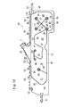
この実施の形態では、カーテンエアバッグ本体2は、図4~7の通り、室内側パネル5(第1パネル)と反室内側パネル6(第2パネル)とを重ね合わせ、これらのパネル5,6同士を線状結合部30~40及び環状結合部41~48により結合することにより、両パネル5,6の間にインフレータ差込部7と膨張室8~17及びガス通過部20~22を形成したものである。
In this embodiment, as shown in FIGS. 4 to 7, the
各線状結合部30~40及び各環状結合部41~48は、パネル5,6同士を気密に結合し、かつカーテンエアバッグ本体2の内圧が設計上限圧力にまで上昇してもパネル5,6同士が離反しないような強固な結合手段(例えば、強度の高い縫糸による縫合や、接着力の高い接着剤による接着、或いは溶着。)により形成されている。パネル5,6を縫合する場合、目止め用接着剤(シーラント)をパネルの縫合予定部に塗布してから縫合してもよく、目止め用接着剤を塗布せずに縫合してもよい。線状結合部の一部(例えば線状結合部32~35)はパネル5,6の相互織込(インターウーブン)により形成されてもよい。
The
線状結合部30は、カーテンエアバッグ本体2を略周回するように延在した周縁結合部である。この線状結合部30は、カーテンエアバッグ本体2の上縁の前後方向途中において断絶しており、これにより、インフレータ差込部7が形成されている。
The
タイパネル3は、自動車の前席の側方に位置する。図4,5の通り、タイパネル3の上辺部は、カーテンエアバッグ本体2の上辺部に沿う上部連結手段3bによってパネル5,6に縫合されている。タイパネル3の下辺部は、カーテンエアバッグ本体2の下辺部に沿う下部連結手段3cによってパネル5,6に縫合されている。上部連結手段3bは上辺側の線状結合部30であってもよく、これとは別の縫合部であってもよい。下部連結手段3cは下辺側の線状結合部30であってもよく、これとは別の縫合部であってもよい。タイパネル3には複数個の空気通過用開口3a(図3b)が設けられている。
図3aの通り、タイパネル3の配置領域(タイパネル配置部)の下方において、カーテンエアバッグ本体2は、下方に延出した延出部2aを有している。この延出部2aを備えたことにより、カーテンエアバッグ本体2は、タイパネル配置部における上下方向長さがその前後の領域における上下方向の長さよりも大きいものとなっている。この延出部2aは、図4の通り上方かつ反室内側に折り返されてタイパネル3の下辺部に下部連結手段3cによって縫合されている。
As shown in FIG. 3a, the curtain airbag
タイルパネル3を平たく広げた状態における上部連結手段3bから下部連結手段3cまでの長さは、タイルパネル3を取り付ける前のカーテンエアバッグ本体2の該上部連結手段3bから下部連結手段3cまでの長さよりも小さい。
The length from the upper connecting means 3b to the lower connecting
カーテンエアバッグ本体2の前部において、上辺側の線状結合部30はV字形に延在しており、このV字の下端部から下方に線状結合部31が延在し、環状結合部41に連なっている。なお、環状結合部41を設けた部分には円形のパッチクロス29が配置され、環状結合部41によってパネル5,6とパッチクロス29とが縫合されている。後述の各環状結合部42~48においても同様にパッチクロスが設けられている。
In the front portion of the
環状結合部41と前辺側の線状結合部30との間が膨張室13となっている。環状結合部41と下辺部の線状結合部30との間はガス通過部20となっている。線状結合部31よりも後方であって、かつタイパネル3よりも若干前方に2個の環状結合部42,43が配置されている。環状結合部42は環状結合部43よりも上方に位置する。環状結合部43は、タイパネル3の下辺と略同一高さに位置している。
The space between the
タイパネル3よりも若干後方に3個の環状結合部44,45,46が配置されている。最も上位の環状結合部44は、インフレータ差込部7の下方に位置する。最も下位の環状結合部46は、タイパネル3の下辺後部の近傍に位置する。環状結合部45は、環状結合部44,46の略中間付近に位置する。環状結合部44,45間に線状結合部36が設けられている。環状結合部45,46間はガス通過部21となっている。
Three
環状結合部42,46間に一直線状に線状結合部32,33が延在し、環状結合部43,44間に一直線状に線状結合部34,35が延在している。
線状結合部32,33と線状結合部34,35とは、交点Mにて交わっている。この交点Mは、タイパネル3の中央点(上下方向及び左右方向の中央の点)よりも若干下方に位置している。この実施の形態では、交点Mは、タイパネル3の前後方向の略中間付近に位置し、かつタイパネル3の下辺から0~250mm特に0~150mm上方に位置することが好ましい。
The
線状結合部32~35は交点MにおいてX字状に交わっており、線状結合部32は交点Mから前方かつ上方に延在し、線状結合部33は交点Mから後方かつ下方に延在し、線状結合部34は交点Mから前方かつ下方に延在し、線状結合部35は交点Mから後方かつ上方に延在している。交点Mは、自動車の前席の側方に位置している。線状結合部35の最後部側は略水平となっている。
The
カーテンエアバッグ本体2内のうち、線状結合部32,35で挟まれた領域が膨張室8であり、線状結合部32,34で挟まれた領域が膨張室9であり、線状結合部34,33で挟まれた領域が膨張室10であり、線状結合部33,35で挟まれた領域が膨張室11である。
In the curtain airbag
カーテンエアバッグ本体2が膨張していない状態において、交点Mから、線状結合部31までの水平距離は約150~450mm特に180~380mm程度が好ましい。環状結合部45は好ましくは交点Mの後方に位置しており、交点Mから環状結合部45までの距離は約150~450mm特に180~380mm程度が好ましい。
In the state where the
環状結合部44は環状結合部45よりも上方かつ若干後方に位置している。そのため、線状結合部36は後方ほど上方となるように斜めに延在している。この線状結合部36の後方に、該線状結合部36と略平行に線状結合部37が設けられている。線状結合部37の下端は、カーテンエアバッグ本体2の下辺側の線状結合部30に連なっている。線状結合部37の上端は、略水平な線状結合部38の前端に連なっている。線状結合部38は、カーテンエアバッグ本体2の上辺の線状結合部30と略平行に後方に向って延在している。
The
線状結合部38の後端は、後方ほど下位となるように斜めに延在した線状結合部39に連なっている。線状結合部39の下端は環状結合部47に連なっている。環状結合部47とカーテンエアバッグ本体2の下辺側の線状結合部30との間はガス通過部22となっている。
The rear end of the
線状結合部37と線状結合部36との間が膨張室12となっている。線状結合部38と上辺部の線状結合部30との間が膨張室14となっている。線状結合部39と後辺側の線状結合部30との間が膨張室15となっている。
The space between the
線状結合部38の前後方向の中間付近の下方に環状結合部48が設けられている。この環状結合部48と下辺側線状結合部30との間に線状結合部40が延在している。この線状結合部40は、後方ほど上位となるように略斜めに延在している。線状結合部40と線状結合部39との間が膨張室16となっている。線状結合部40と線状結合部37,38との間が膨張室17となっている。
An
カーテンエアバッグ本体2の前辺及び後辺からは、カーテンエアバッグ本体2を車体のAピラー及びCピラーに連結するためのテザー51,52が延設されている。また、カーテンエアバッグ本体2の上辺からは、カーテンエアバッグ本体2を車体のルーフサイドレールに連結するための取付片53が延設されている。
From the front side and the rear side of the curtain airbag
このカーテンエアバッグ1のインフレータ差込口7にインフレータ(ガス発生器)99が挿入され、このインフレータ差込口7の外周にバンド等の締結具が締め付けられることにより、インフレータ99が取り付けられる。このインフレータは、自動車のルーフサイドレールに固定される。
The inflator 99 is attached by inserting an inflator (gas generator) 99 into the
図示は省略するが、このカーテンエアバッグ1は、図2,4のように、カーテンエアバッグ本体2の延出部2aを上方に且つ反室内側に折り返した後、前後方向に細長く折り畳まれた状態で自動車のルーフサイド部(車室内の天井面と側面との境界部分)に沿って配置される。テザー51,52はAピラー、Cピラーに連結され、各取付片53はボルトやリベット等の固着具でルーフサイドレールに固着される。カーテンエアバッグ1の折り畳み体は、ルーフガーニッシュにより覆われる。
Although not shown in the drawings, the
このカーテンエアバッグ1は、多数の縦セルを設けていないので、その折り畳み体の嵩(パッケージボリューム)が比較的小さい。
Since this
このように構成されたカーテンエアバッグ装置を備えた自動車が衝突あるいは横転した場合、インフレータ99が作動し、このインフレータ99からカーテンエアバッグ本体2内にガスが供給されてカーテンエアバッグ本体2が膨張を開始する。このカーテンエアバッグ1は、ルーフガーニッシュを押し開けて車室内の側面に沿って下方に展開する。
When the automobile equipped with the curtain airbag device configured as described above collides or rolls over, the
この際、インフレータからカーテンエアバッグ本体2内に供給されたガスは、ダクトパネル4(図3a)によって前方と後方とに分流される。前方に分流したガスは、膨張室8,9,10,12,11を順次に膨張させる。膨張室9から膨張室10に回り込むガスの一部は、ガス通過部20から膨張室13に流入し、膨張室13を膨張させる。
At this time, the gas supplied from the inflator into the
タイパネル3の上下方向長さがカーテンエアバッグ本体2のタイパネル配置部の長さ(図3aのように、タイパネル3を連結していない状態の長さ)よりも小さいので、各膨張室8~11が膨張すると、図5の通り、交点M付近がタイパネル3から室内側に向って突出するようにカーテンエアバッグ本体2が膨張する。交点Mは、好ましくは、自動車の前席乗員(運転者又は助手席乗員)の頭部の側方に位置する。
Since the vertical length of the
ダクトパネル4によって後方に分流したガスは、カーテンエアバッグ本体2内の上辺に沿って流れ、まず膨張室14を膨張させた後、最後部の膨張室15を膨張させ、次いでガス通過部22を通り、各膨張室16,17を順次に膨張させる。
The gas shunted rearward by the
カーテンエアバッグ本体2が膨張した状態において、タイパネル配置部においては、図5,7のように、4個の膨張室8~11が交点Mから上方、前方、下方及び後方に向って延在し、交点Mとタイパネル3との間に略々四角錐(ピラミッド)形状のスペースSが形成される。この交点M付近が乗員を受け止めた場合、各膨張室8~11が減容すると共に、スペースSの厚み(交点Mからタイパネル3までの距離)が小さくなるようにカーテンエアバッグ本体2が変形し、乗員の運動エネルギーが吸収される。
In the state in which the
この実施の形態では、図8のように、乗員が交点M付近に当った場合乗員からカーテンエアバッグ1に加えられる力F1は、前後及び上下の4方向に延在する膨張室8~11によって対抗される。即ち、力F1は上方向の分力FU、前方向の分力FF、下方向の分力FD、後方向の分力FRに分力され、各分力FU、FF、FD、FRが各膨張室8~11によって対抗される。そのため、カーテンエアバッグ本体2の内圧が低くても各分力FU、FF、FD、FRに対抗し、乗員のエネルギーを吸収することができる。従って、インフレータとして小容量のものを用いれば足りる。
In this embodiment, as shown in FIG. 8, when the occupant hits the intersection M, the force F 1 applied to the
これに対し、特許文献1の図7(c)のように横から見て三角形となる三角柱形状に膨張するカーテンエアバッグの場合は、図9のように、乗員からカーテンエアバッグに加えられる力F2は上方に向う分力FUと下方に向う分力FDとに分力されるため、各分力FU及びFDは図8の分力FU及びFDよりも大きくなる。従って、カーテンエアバッグ内圧を図8の場合よりも高くして大きな各分力FU、FDに対応できるようにする必要がある。このため、インフレータとして高出力のものを用いることが必要となる。
On the other hand, in the case of a curtain airbag that inflates into a triangular prism shape as viewed from the side as shown in FIG. 7C of
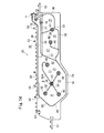
上記実施の形態では、カーテンエアバッグ本体2の最前部に膨張室13を設けているが、図10のカーテンエアバッグ本体2Aのようにこの膨張室13を省略してもよい。また、図10のように、前記交点Mに環状結合部50を設け、交点M付近におけるパネル5,6同士の結合強度を高くしてもよい。線状結合部32,33,34,35Aは、この環状結合部50から放射方向に延在している。
In the above embodiment, the
なお、図10では環状結合部44が省略され、環状結合部45が前記カーテンエアバッグ本体2におけるよりも若干上位に配置されている。線状結合部35Aは、環状結合部50から前記線状結合部35と同様に、後方かつ上方に延在しているが、その後部は、環状結合部45よりも上位において略水平後方に延在している。この線状結合部35Aは、環状結合部45よりも後方において下方に略J字状に湾曲して環状結合部45に連なっている。
In FIG. 10, the
カーテンエアバッグ本体2Aのその他の構成はカーテンエアバッグ本体2と同一であり、同一符号は同一部分を示している。
The other configuration of the
このカーテンエアバッグ本体2Aの膨張作動は、膨張室13がない点を除き、前記カーテンエアバッグ本体2と同じである。このカーテンエアバッグ本体2Aを備えたカーテンエアバッグも、前記カーテンエアバッグ1と同様の作用効果を有する。
The expansion operation of the
上記カーテンエアバッグ本体2,2Aは、ピラミッド状に膨張する部分を前席側にのみ備えているが、図11a,11bのカーテンエアバッグ本体2Bのように、車両後席に臨む位置にもピラミッド状膨張部を設けてもよい。
The curtain airbag
このカーテンエアバッグ2Bでは、図11aの通り、カーテンエアバッグ本体後部の環状結合部47の上方に環状結合部51が設けられ、環状結合部47の後方に環状結合部52が設けられ、該環状結合部51の後方かつ環状結合部52の上方に環状結合部53が設けられている。環状結合部51は、線状結合部38,39から離隔している。
In this
環状結合部51,52間に一直線状に線状結合部54,55が延在し、環状結合部47,53間に一直線状に線状結合部56,57が延在している。
線状結合部54,55と線状結合部56,57は、交点Nにて交わっている。この交点Nは、後席用のタイパネル3Rの中央点(上下方向及び左右方向の中央の点)よりも若干下方に位置している。この実施の形態では、交点Nは、タイパネル3Rの前後方向の略中間付近に位置し、かつタイパネル3Rの下辺から0~250mm特に0~150mm上方に位置することが好ましい。タイパネル3Rは、空気通過用開口を有する。
The
線状結合部54~57は交点NにおいてX字状に交わっており、線状結合部54は交点Nから前方かつ上方に延在し、線状結合部55は交点Nから後方かつ下方に延在し、線状結合部56は交点Nから前方かつ下方に延在し、線状結合部57は交点Nから後方かつ上方に延在している。
The
カーテンエアバッグ本体2B内のうち、線状結合部54,57で挟まれた領域が膨張室58であり、線状結合部57,55で挟まれた領域が膨張室59であり、線状結合部55,56で挟まれた領域が膨張室60であり、線状結合部56,54で挟まれた領域が膨張室61である。
In the curtain airbag
カーテンエアバッグ本体2Bが膨張していない状態において、交点Nから、線状結合部39までの水平距離は約150~450mm特に180~380mm程度が好ましい。交点Nからカーテンエアバッグ本体2の後辺の線状結合部30までの距離は約150~450mm特に180~380mm程度が好ましい。
In the state where the
カーテンエアバッグ本体2Bの後部の下辺部分には、下方に延出した延出部2bが設けられており、タイパネル3Rの下辺部は、この延出部2bの下辺に対し縫合等により結合されている。タイパネル3Rの上辺部は、カーテンエアバッグ本体2Bの上辺に対し縫合等により結合されている。タイルパネル3Rを平たく広げた状態における該タイパネル3Rの上辺部から下辺部までの長さは、タイルパネル3Rを取り付ける前のカーテンエアバッグ本体2Bの上辺から延出部2bの下辺までの長さよりも小さい。
The lower part of the rear part of the curtain airbag
カーテンエアバッグを折り畳む場合は、延出部2a,2bは、いずれも、カーテンエアバッグ本体2Bの反室内側に折り返された図11bに示す状態とされる。この状態から、カーテンエアバッグが前後方向に細長く折り畳まれ、自動車のルーサイドに設置される。タイパネル3Rは、自動車の後席の側方に位置する。交点Nは、好ましくは、後席乗員の頭部の側方に位置する。
When the curtain airbag is folded, the extending
なお、このカーテンエアバッグ本体2Bでは、前記カーテンエアバッグ本体2,2Aで設けられていた環状結合部48と、それに連なる線状結合部40が省略され、線状結合部37,38,39及びカーテンエアバッグ下辺側の線状結合部30によって囲まれた単一の膨張室62が設けられている。この膨張室62は、ガス通過部22を介して膨張室60に連通している。
In the curtain airbag
図11a,11bのカーテンエアバッグ本体2Bのその他の構成は図10のカーテンエアバッグ本体2Aと同じであり、同一符号は同一部分を示している。
Other configurations of the
インフレータが作動したときの図11a,11bのカーテンエアバッグ本体2Bの前半側の膨張作動は前記カーテンエアバッグ本体2Aと同じである。カーテンエアバッグ本体2Bの後半側の膨張作動は次の通りである。即ち、ダクトパネル4(図3a)によって後方に分流されたガスは、膨張室14を膨張させ、次いで膨張室58を膨張させる。なお、膨張室58に向うガスの一部が膨張室61に流れ込み、膨張室61を膨張させる。膨張室58を通過したガスは膨張室59,60,62を順次に膨張させる。
When the inflator is activated, the inflating operation on the front half side of the
図12のカーテンエアバッグ本体2Cは、後席にのみピラミッド状膨張部を設けたものであり、前半側にあってはX字状に交差する線状結合部32~35Aは設けられていない。その代りに、カーテンエアバッグ本体2Cの前部下辺側の線状結合部30から立ち上がる線状結合部68と、インフレータ差込口7の下方において前後方向に延在する線状結合部69と、該線状結合部69に連なり、L字形に延在した線状結合部70とが設けられている。線状結合部68の上端には環状結合部65が設けられ、線状結合部69の両端に環状結合部66,67が設けられている。線状結合部70は、線状結合部69の途中部分から下方に延在し、次いで後方に延在して線状結合部37の下部に連なっている。
The curtain airbag
線状結合部68の前方側が膨張室71となっており、線状結合部68,70間が膨張室72となっており、線状結合部70とカーテンエアバッグ下辺側線状結合部30との間が膨張室73となっている。この膨張室73が膨張室62に連通している。この実施の形態では、カーテンエアバッグ後部の環状結合部47は下辺側線状結合部30に重なっており、膨張室62へは膨張室60からではなく膨張室73からガスが流入する。
The front side of the
このカーテンエアバッグ本体2Cの前半側には延出部2aは設けられていない。このカーテンエアバッグ本体2Cのその他の構成は図11aのカーテンエアバッグ本体2Bと同じであり、同一符号は同一部分を示している。
The
インフレータが作動したときのカーテンエアバッグ本体2Cの膨張室14,58~61の膨張作動はカーテンエアバッグ本体2Bと同一である。カーテンエアバッグ本体2Cの前半側にあっては、インフレータからのガスがダクトパネル4(図3a)によって前方に流出し、まず膨張室71を膨張させる。その後、ガスが膨張室72,73を膨張させ、次いで膨張室62を膨張させる。
The expansion operation of the
上記実施の形態では、いずれもインフレータ差込口7がカーテンエアバッグ本体の上辺の前後方向中間付近に設けられているが、カーテンエアバッグ本体の前部や後部に設けられてもよい。その一例を図13,14に示す。
In any of the above embodiments, the
図13のカーテンエアバッグ本体2Dは、インフレータ差込口7がカーテンエアバッグ本体2Dの後辺上部に設けられている。このカーテンエアバッグ本体2Dにあっては、線状結合部38と線状結合部39との接続部から後方に線状結合部77が延在している。この線状結合部77の後端に環状結合部76が設けられている。環状結合部76よりも後方に環状結合部75が設けられており、カーテンエアバッグ本体後辺の線状結合部30が該環状結合部75に連なっている。環状結合部75から後方に、インフレータ差込口7の下辺に沿って線状結合部79が延設されている。環状結合部76,75間は、膨張室15へのガス流入用のガス通過部78となっている。このカーテンエアバッグ本体2Dのその他の構成は交点Mに環状結合部50が設けられていない点を除いて、図10のカーテンエアバッグ本体2Aと同じであり、同一符号は同一部分を示している。
In the curtain airbag
インフレータ差込口7に設置されたインフレータからのガスは、カーテンエアバッグ本体2D上辺の線状結合部30と線状結合部77,38間の膨張室14を通ってカーテンエアバッグ本体2Dの前半側に供給され、膨張室8~12を膨張させ、ピラミッド状となる。インフレータからのガスの一部は、ガス通過部78から膨張室15に流入し、膨張室15,16,17を順次に膨張させる。
The gas from the inflator installed in the
図14のカーテンエアバッグ本体2Eでは、インフレータ差込口7は、カーテンエアバッグ本体2Eの上辺最後部に設けられている。このカーテンエアバッグ本体2Eでは、環状結合部75は環状結合部76の後方斜め上方に位置している。なお、インフレータ差込口は、図14に示すよりも前方側に設けられてもよい。
In the curtain airbag
カーテンエアバッグ本体2Eのその他の構成は、図13のカーテンエアバッグ本体2Dと同一であり、同一符号は同一部分を示している。また、インフレータが作動したときのカーテンエアバッグ本体2Eの膨張作動もカーテンエアバッグ本体2Dと同一である。
The other configuration of the
本発明のカーテンエアバッグ特に図1~7のカーテンエアバッグ1は、スモールオーバーラップ衝突(ナローオフセット衝突)時の運転席乗員の拘束に好適である。即ち、スモールオーバーラップ衝突に際して図15aのようにカーテンエアバッグ1と運転席エアバッグ90とが膨張し、運転席乗員が拘束される。この場合、ピラミッド状に膨張したカーテンエアバッグ1の前半部が乗員頭部Hに反力を与える。また、カーテンエアバッグ1の最前部に膨張厚みの大きな膨張室13を配置しているので、乗員頭部HはAピラー91に向う方向ではなく、図15b,15cのように運転席エアバッグ90に向って案内され、最終的に運転席エアバッグ90で拘束される。
The curtain airbag of the present invention, particularly the
上記実施の形態では、ピラミッド状の乗員拘束部が形成されるように放射4方向に線状結合部を設けているが、放射3方向又は5方向以上でもよい。また、上記実施の形態では、4条の放射状線状結合部間にすべて膨張室を形成しているが、一部については膨張室ではなく非膨張パネルによって構成されてもよい。 In the above embodiment, linear coupling portions are provided in the four radiation directions so that a pyramid-shaped occupant restraint portion is formed, but three or more radiation directions may be provided. Moreover, in the said embodiment, although the expansion | swelling chamber is all formed between the 4 radial linear coupling | bond parts, you may be comprised by the non-expansion panel instead of an expansion chamber.
上記の実施の形態は、本発明の一例を示すものであり、本発明は上記の実施の形態に限定されない。 The above embodiment shows an example of the present invention, and the present invention is not limited to the above embodiment.
本出願は、2013年10月22日付で出願された日本特許出願2013-219277に基づいており、その全体が引用により援用される。 This application is based on Japanese Patent Application No. 2013-219277 filed on October 22, 2013, which is incorporated by reference in its entirety.
1 カーテンエアバッグ
2,2A~2E カーテンエアバッグ本体
3,3R タイパネル
3b 上部連結手段
3c 下部連結手段
4 ダクトパネル
5 第1パネル
6 第2パネル
7 インフレータ差込部
8~17,58~62,71~73 膨張室
20~22,78 ガス通過部
30~40,54~57,70,77,79 線状結合部
41~48,51~53,66~67,75,76 環状結合部
DESCRIPTION OF
Claims (10)
インフレータからのガスによって膨張するカーテンエアバッグ本体と、
該カーテンエアバッグ本体の車両前後方向の途中の一部(以下、タイパネル配置部という。)における反室内側面に配置されており、該カーテンエアバッグ本体の上部及び下部に対しそれぞれ上部連結手段及び下部連結手段によって連結されたタイパネルと、
を備えており、
該カーテンエアバッグ本体は、室内側の第1パネルと、反室内側の第2パネルと、該第1パネルと第2パネルとを結合する結合部とを有しており、
該結合部は、該第1パネル及び第2パネルの周縁部に沿う周縁結合部と、該周縁結合部よりも内側に位置する内側結合部とを有しており、
前記タイパネルの前記上部連結手段から下部連結手段までの長さは、前記カーテンエアバッグ本体の前記上部連結手段から下部連結手段までの長さよりも小さいカーテンエアバッグにおいて、
前記内側結合部の一部として、前記タイパネル配置部の中央部又はその近傍から放射3方向又はそれ以上の放射多方向に延在する放射状結合部が設けられており、
少なくとも3方向の該放射状結合部は、該タイパネル配置部の該中央部又はその近傍から斜め上方又は斜め下方に延在していることを特徴とするカーテンエアバッグ。 A curtain airbag that deploys downward along the side of the vehicle compartment,
A curtain airbag body that is inflated by gas from the inflator;
The curtain airbag body is disposed on the side of the interior of the curtain airbag body in the middle of the vehicle longitudinal direction (hereinafter referred to as a tie panel placement section). Tie panels connected by lower connecting means;
With
The curtain airbag main body has a first panel on the indoor side, a second panel on the non-indoor side, and a coupling portion that couples the first panel and the second panel.
The joint has a peripheral joint along the peripheral edge of the first panel and the second panel, and an inner joint located on the inner side of the peripheral joint,
In the curtain airbag, the length from the upper connecting means to the lower connecting means of the tie panel is smaller than the length from the upper connecting means to the lower connecting means of the curtain airbag body,
As a part of the inner coupling part, a radial coupling part extending in three or more radial directions from the central part of the tie panel arrangement part or the vicinity thereof is provided,
The curtain airbag according to claim 1, wherein the radial coupling portions in at least three directions extend obliquely upward or obliquely downward from the central portion of the tie panel placement portion or the vicinity thereof.
Priority Applications (1)
| Application Number | Priority Date | Filing Date | Title |
|---|---|---|---|
| US15/029,401 US10017146B2 (en) | 2013-10-22 | 2014-08-05 | Curtain airbag and curtain airbag device |
Applications Claiming Priority (2)
| Application Number | Priority Date | Filing Date | Title |
|---|---|---|---|
| JP2013219277A JP6183142B2 (en) | 2013-10-22 | 2013-10-22 | Curtain airbag and curtain airbag device |
| JP2013-219277 | 2013-10-22 |
Publications (1)
| Publication Number | Publication Date |
|---|---|
| WO2015059977A1 true WO2015059977A1 (en) | 2015-04-30 |
Family
ID=52992588
Family Applications (1)
| Application Number | Title | Priority Date | Filing Date |
|---|---|---|---|
| PCT/JP2014/070580 Ceased WO2015059977A1 (en) | 2013-10-22 | 2014-08-05 | Curtain airbag and curtain airbag device |
Country Status (3)
| Country | Link |
|---|---|
| US (1) | US10017146B2 (en) |
| JP (1) | JP6183142B2 (en) |
| WO (1) | WO2015059977A1 (en) |
Cited By (1)
| Publication number | Priority date | Publication date | Assignee | Title |
|---|---|---|---|---|
| US10479314B2 (en) | 2017-03-08 | 2019-11-19 | Joyson Safety Systems Japan K.K. | Curtain airbag and curtain airbag device |
Families Citing this family (18)
| Publication number | Priority date | Publication date | Assignee | Title |
|---|---|---|---|---|
| JP6183142B2 (en) * | 2013-10-22 | 2017-08-23 | タカタ株式会社 | Curtain airbag and curtain airbag device |
| JP6102857B2 (en) * | 2014-08-01 | 2017-03-29 | トヨタ自動車株式会社 | Curtain airbag device for vehicle |
| KR102203274B1 (en) * | 2014-08-27 | 2021-01-18 | 현대모비스 주식회사 | Curtain Airbag Of Vehicle |
| JP6447122B2 (en) * | 2014-12-26 | 2019-01-09 | 豊田合成株式会社 | Head protection airbag device |
| JP6578822B2 (en) * | 2015-08-28 | 2019-09-25 | Joyson Safety Systems Japan株式会社 | Curtain airbag |
| JP6069451B1 (en) * | 2015-09-30 | 2017-02-01 | 富士重工業株式会社 | Vehicle occupant protection device |
| KR101776506B1 (en) * | 2016-06-08 | 2017-09-08 | 현대자동차주식회사 | Curtain airbag for vehicle |
| JP6597494B2 (en) * | 2016-06-23 | 2019-10-30 | 豊田合成株式会社 | Curtain airbag |
| KR102571842B1 (en) * | 2016-09-09 | 2023-08-30 | 현대모비스 주식회사 | Curtain airbag apparatus for car |
| JP6558340B2 (en) * | 2016-10-07 | 2019-08-14 | トヨタ自動車株式会社 | Curtain airbag device for vehicle |
| JP6540647B2 (en) * | 2016-10-07 | 2019-07-10 | トヨタ自動車株式会社 | Curtain airbag system for vehicles |
| US10144385B2 (en) * | 2016-12-19 | 2018-12-04 | Ford Global Technologies, Llc | Side curtain including a strip connected to an inboard panel |
| KR102293580B1 (en) * | 2017-06-08 | 2021-08-26 | 현대모비스 주식회사 | Curtain airbag apparatus |
| US10836342B2 (en) * | 2017-10-31 | 2020-11-17 | Toyoda Gosei Co., Ltd. | Airbag for head protection |
| DE102018129578A1 (en) * | 2018-11-23 | 2020-05-28 | Dalphi Metal Espana, S.A. | GAS BAG MODULE FOR A VEHICLE PASSENGER RESTRAINT SYSTEM |
| JP7777584B2 (en) * | 2020-11-10 | 2025-11-28 | オートリブ ディベロップメント エービー | Inflatable airbag |
| KR20230157715A (en) * | 2022-05-10 | 2023-11-17 | 현대모비스 주식회사 | Air bag for vehicle |
| KR20250145881A (en) * | 2024-03-29 | 2025-10-13 | 현대모비스 주식회사 | Curtain airbag apparatus |
Citations (5)
| Publication number | Priority date | Publication date | Assignee | Title |
|---|---|---|---|---|
| JP2000006747A (en) * | 1998-06-23 | 2000-01-11 | Takata Kk | Protective bag for automobile occupant head |
| JP2001287612A (en) * | 2000-04-11 | 2001-10-16 | Daihatsu Motor Co Ltd | Air bag device |
| JP2006137413A (en) * | 2004-03-17 | 2006-06-01 | Takata Corp | Airbag system |
| JP2006142964A (en) * | 2004-11-18 | 2006-06-08 | Takata Petri Ag | Head protecting air bag and head protecting air bag device |
| JP2012071718A (en) * | 2010-09-29 | 2012-04-12 | Nippon Plast Co Ltd | Curtain airbag device |
Family Cites Families (20)
| Publication number | Priority date | Publication date | Assignee | Title |
|---|---|---|---|---|
| US5730464A (en) * | 1995-08-11 | 1998-03-24 | General Motors Corporation | Air bag module with tether |
| EP0771694A2 (en) * | 1995-11-03 | 1997-05-07 | Morton International, Inc. | Airbag tether and attachment seam |
| JP4120144B2 (en) * | 1999-09-21 | 2008-07-16 | タカタ株式会社 | Protective bag, protective device for automobile occupant head and automobile |
| JP2003072500A (en) * | 2001-09-07 | 2003-03-12 | Takata Corp | Protective bag of automobile occupant head part |
| JP3891066B2 (en) | 2002-07-30 | 2007-03-07 | 豊田合成株式会社 | Side airbag device |
| US20030168836A1 (en) | 2002-03-11 | 2003-09-11 | Eiji Sato | Side airbag apparatus |
| JP2004210257A (en) * | 2002-12-18 | 2004-07-29 | Takata Corp | Head part protection air bag and head part protection air bag device |
| JP4320591B2 (en) * | 2003-12-19 | 2009-08-26 | タカタ株式会社 | Curtain airbag device |
| EP1577171B1 (en) | 2004-03-17 | 2012-11-14 | Takata AG | Airbag device |
| DE102005002085B4 (en) | 2004-03-17 | 2013-09-05 | TAKATA Aktiengesellschaft | Side air bag device |
| JP4161997B2 (en) | 2005-10-17 | 2008-10-08 | トヨタ自動車株式会社 | Airbag device |
| EP2174841B1 (en) | 2007-07-11 | 2014-04-23 | Asahi Kasei Engineering Corporation | Curtain bag |
| JP2011051526A (en) | 2009-09-03 | 2011-03-17 | Autoliv Development Ab | Head protecting airbag device |
| US8740247B1 (en) * | 2012-12-27 | 2014-06-03 | Nissan North America, Inc. | Airbag assembly |
| US9114776B2 (en) * | 2013-05-09 | 2015-08-25 | GM Global Technology Operations LLC | Vehicle and an airbag assembly for the vehicle |
| JP6183142B2 (en) * | 2013-10-22 | 2017-08-23 | タカタ株式会社 | Curtain airbag and curtain airbag device |
| JP6398430B2 (en) * | 2014-07-30 | 2018-10-03 | Joyson Safety Systems Japan株式会社 | Curtain airbag and curtain airbag device |
| KR102203274B1 (en) * | 2014-08-27 | 2021-01-18 | 현대모비스 주식회사 | Curtain Airbag Of Vehicle |
| KR102239009B1 (en) * | 2014-10-17 | 2021-04-13 | 현대모비스 주식회사 | Curtain Airbag Of Vehicle |
| JP6504049B2 (en) * | 2015-12-28 | 2019-04-24 | 豊田合成株式会社 | Head protection airbag device |
-
2013
- 2013-10-22 JP JP2013219277A patent/JP6183142B2/en not_active Expired - Fee Related
-
2014
- 2014-08-05 WO PCT/JP2014/070580 patent/WO2015059977A1/en not_active Ceased
- 2014-08-05 US US15/029,401 patent/US10017146B2/en not_active Expired - Fee Related
Patent Citations (5)
| Publication number | Priority date | Publication date | Assignee | Title |
|---|---|---|---|---|
| JP2000006747A (en) * | 1998-06-23 | 2000-01-11 | Takata Kk | Protective bag for automobile occupant head |
| JP2001287612A (en) * | 2000-04-11 | 2001-10-16 | Daihatsu Motor Co Ltd | Air bag device |
| JP2006137413A (en) * | 2004-03-17 | 2006-06-01 | Takata Corp | Airbag system |
| JP2006142964A (en) * | 2004-11-18 | 2006-06-08 | Takata Petri Ag | Head protecting air bag and head protecting air bag device |
| JP2012071718A (en) * | 2010-09-29 | 2012-04-12 | Nippon Plast Co Ltd | Curtain airbag device |
Cited By (1)
| Publication number | Priority date | Publication date | Assignee | Title |
|---|---|---|---|---|
| US10479314B2 (en) | 2017-03-08 | 2019-11-19 | Joyson Safety Systems Japan K.K. | Curtain airbag and curtain airbag device |
Also Published As
| Publication number | Publication date |
|---|---|
| JP2015080993A (en) | 2015-04-27 |
| JP6183142B2 (en) | 2017-08-23 |
| US10017146B2 (en) | 2018-07-10 |
| US20160221527A1 (en) | 2016-08-04 |
Similar Documents
| Publication | Publication Date | Title |
|---|---|---|
| JP6183142B2 (en) | Curtain airbag and curtain airbag device | |
| JP6398430B2 (en) | Curtain airbag and curtain airbag device | |
| JP6080344B2 (en) | Airbag device | |
| JP6920030B2 (en) | One-way valve for multi-chamber airbags | |
| JP4075463B2 (en) | Head protection airbag and head protection airbag device | |
| CN205113240U (en) | Curtain airbag apparatus | |
| JP5808983B2 (en) | Airbag device | |
| JP4481248B2 (en) | Side curtain airbag | |
| JP5176923B2 (en) | Side airbag device | |
| JP2004210257A (en) | Head part protection air bag and head part protection air bag device | |
| CN105793119A (en) | Cost-effective use of integrally woven fabrics for curtain airbags | |
| JP2011511734A (en) | Airbag | |
| JP4748141B2 (en) | Head protection airbag and head protection airbag device | |
| JP5232422B2 (en) | Side impact airbag, side impact airbag device, vehicle seat | |
| KR20150001100A (en) | Side curtain airbag for vehicle | |
| JP2008056242A5 (en) | ||
| JP4419696B2 (en) | Curtain airbag device | |
| JP2018070102A (en) | Airbag for rear seat | |
| JP4572485B2 (en) | Car occupant head protective bag | |
| JP2008201265A (en) | Curtain airbag and curtain airbag device | |
| JP7186108B2 (en) | Curtain airbag and curtain airbag device | |
| JP6578822B2 (en) | Curtain airbag | |
| JP2018161925A (en) | Side airbag device | |
| JP2009040265A (en) | Head protection airbag device | |
| JP4850579B2 (en) | Curtain airbag device |
Legal Events
| Date | Code | Title | Description |
|---|---|---|---|
| WWE | Wipo information: entry into national phase |
Ref document number: 15029401 Country of ref document: US |
|
| NENP | Non-entry into the national phase |
Ref country code: DE |
|
| 121 | Ep: the epo has been informed by wipo that ep was designated in this application |
Ref document number: 14855475 Country of ref document: EP Kind code of ref document: A1 |
|
| 122 | Ep: pct application non-entry in european phase |
Ref document number: 14855475 Country of ref document: EP Kind code of ref document: A1 |