WO2011097764A1 - Equipment and method for inter-cell interference coordination in relay auxiliary cellular network - Google Patents
Equipment and method for inter-cell interference coordination in relay auxiliary cellular network Download PDFInfo
- Publication number
- WO2011097764A1 WO2011097764A1 PCT/CN2010/000204 CN2010000204W WO2011097764A1 WO 2011097764 A1 WO2011097764 A1 WO 2011097764A1 CN 2010000204 W CN2010000204 W CN 2010000204W WO 2011097764 A1 WO2011097764 A1 WO 2011097764A1
- Authority
- WO
- WIPO (PCT)
- Prior art keywords
- sector
- relay
- adjacent
- resource
- distribution density
- Prior art date
- Legal status (The legal status is an assumption and is not a legal conclusion. Google has not performed a legal analysis and makes no representation as to the accuracy of the status listed.)
- Ceased
Links
Classifications
-
- H—ELECTRICITY
- H04—ELECTRIC COMMUNICATION TECHNIQUE
- H04W—WIRELESS COMMUNICATION NETWORKS
- H04W16/00—Network planning, e.g. coverage or traffic planning tools; Network deployment, e.g. resource partitioning or cells structures
- H04W16/02—Resource partitioning among network components, e.g. reuse partitioning
- H04W16/10—Dynamic resource partitioning
-
- H—ELECTRICITY
- H04—ELECTRIC COMMUNICATION TECHNIQUE
- H04W—WIRELESS COMMUNICATION NETWORKS
- H04W16/00—Network planning, e.g. coverage or traffic planning tools; Network deployment, e.g. resource partitioning or cells structures
- H04W16/02—Resource partitioning among network components, e.g. reuse partitioning
- H04W16/04—Traffic adaptive resource partitioning
-
- H—ELECTRICITY
- H04—ELECTRIC COMMUNICATION TECHNIQUE
- H04W—WIRELESS COMMUNICATION NETWORKS
- H04W84/00—Network topologies
- H04W84/02—Hierarchically pre-organised networks, e.g. paging networks, cellular networks, WLAN [Wireless Local Area Network] or WLL [Wireless Local Loop]
- H04W84/04—Large scale networks; Deep hierarchical networks
- H04W84/042—Public Land Mobile systems, e.g. cellular systems
- H04W84/047—Public Land Mobile systems, e.g. cellular systems using dedicated repeater stations
Definitions
- the present invention relates to interference coordination methods and apparatus in a cellular system, and more particularly to an apparatus and method for inter-cell interference coordination in a relay-assisted cellular network. Background technique
- Multi-hop relay technology has recently been widely discussed in the 3rd Generation Partnership Project Advanced Long Term Evolution (3GPP LTE-A) and Worldwide Interoperability for Microwave Access (WiMAX), both of which select OFDMA as the downlink transmission scheme.
- 3GPP LTE-A 3rd Generation Partnership Project Advanced Long Term Evolution
- WiMAX Worldwide Interoperability for Microwave Access
- each user terminal can access a base station eNode-B (eNB) or a relay node (RN) based on certain UE access principles (e.g., maximum received signal power, minimum distance).
- the link between the eNB and the UE it serves (called a macro UE) is called a direct link; at the relay node (RN) and the UE it serves (called The link between the UEs is called a relay access link; the link between the eNB and its subordinate RN is called a relay backhaul link.
- these three links occupy the entire frequency band of the cell.
- inter-cell interference In a relay enhanced multi-cell communication system, inter-cell interference (ICI) is the primary source of downlink interference.
- Some inter-cell interference coordination (ICIC) techniques based on fractional frequency reuse (FFR) are proposed.
- FFR fractional frequency reuse
- FFR only cell edge UEs (i.e., relay UEs) are allowed to operate on a small portion of all available subbands. The frequency band portion is allocated such that edges of adjacent cells operate on mutually orthogonal frequency bands to avoid inter-cell interference. Since the cell center user is closer to the eNB and thus protected from co-channel interference, the cell center UE (i.e., macro UE) will operate on all or a major portion of the available frequency band without orthogonality restrictions.
- FFR Partial Frequency Multiplexing
- the reuse factor 3 portion of the frequency band is referred to as a cell edge band (using a sub-relay UE), and the reuse factor 1 portion is referred to as a cell center band (for relay backhaul and macro UE).
- Figure 1 shows a schematic diagram of a prior art static ICIC scheme.
- a cell edge band is allocated for the relay UE, and a cell center band is allocated for the macro UE, and the relay backhaul link can share the cell edge band with the relay UE or share the cell center band with the macro UE.
- the cell served by the eNB includes three sectors 0, 1, and 2, the cell edge band F0 is allocated to the relay UE of sector 0, and the cell edge band F1 is allocated to the relay UE of sector 1 as a fan.
- the relay UE of the area 2 allocates the cell edge frequency band F2; and allocates the cell central frequency band F3 for the macro UEs of the sectors 0, 1, and 2.
- the frequency bands F0, F1, F2, and F3 are orthogonal to each other.
- Figure 2 shows a typical LTE FDD downlink frame structure.
- each downlink frame is 10 ms long and consists of 20 (from 0 to 19) time slots of length 0.5 ms.
- a subframe is defined as consecutive slots, where subframe i consists of slots 2i and 2i+1.
- PRBs physical resource blocks
- Fig. 3 shows a resource distribution diagram of the static ICIC scheme in the case of the frame structure shown in Fig. 2.
- the relay UEs of sectors 0, 1, and 2 are each allocated 6 PRBs, that is, the sector edge bands F0 (corresponding to PRB 1-PRB 6) are allocated for sectors 0, 1, and 2, respectively.
- the present invention proposes an apparatus and method for performing inter-cell interference coordination ICIC in a relay assisted cell.
- an apparatus for performing inter-cell interference coordination ICIC in a relay assisted cell includes: a relay overload determining apparatus, for a sector served by the apparatus, according to the sector The load information of the adjacent sector is determined to be a relay overload of the sector or a relay overload of a neighboring sector of the sector; a relay resource borrowing device if an adjacent fan relative to the sector The relay of the sector is overloaded, so that the sector borrows the relay resources released by the adjacent sectors of the sector; the relay resource release device, if relative to the sector The relay of the adjacent sector of the sector is overloaded, and according to the load signal of the adjacent sector Information to release the relay resources that have been allocated for the sector.
- the relay overload determining apparatus may include: a resource distribution density calculating unit, calculating a resource distribution density in the sector and two types of neighbors of the sector according to load information of adjacent sectors of the sector Average resource distribution density of the sector; a relay overload determining unit that compares the calculated resource distribution density in the sector with an average resource distribution density in any of the adjacent sectors, if the fan If the distribution density of the relay resources in the area is smaller than the average resource distribution density of the adjacent sectors of the sector, determining that the sector is overloaded with respect to the adjacent sectors of the type, if If the distribution density of the relay resources in the sector is greater than the average resource distribution density of the adjacent sectors of the sector, then it is determined that the relay of the adjacent sectors is overloaded with respect to the sector.
- m' m' ⁇ 2
- i denotes sector i
- k' denotes neighbor cell k' of cell k
- i' denotes adjacent sector of sector i
- subscripts 1 and 2 of i' denote adjacent sectors of sector i, respectively
- the two categories of i', f ki denote the total number of PRBs allocated for the relay user equipment UE in the cell k sector i
- N ki denote the number of relay UEs in the cell k sector i.
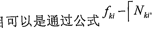
- the number of relay resources that have been allocated for the sector can be calculated by the formula "' I kl ki I ).
- the relay resource borrowing device may include: a borrowing condition determining unit that determines whether the adjacent sector of the sector is overloaded in a case where the relay of the sector is overloaded with respect to any type of adjacent sectors of the sector The common relay resource is released, and the relay resource borrowing unit causes the sector to borrow the adjacent sector of the sector in the case where the adjacent sector releases the common relay resource.
- the common relay resources that are released may include: a borrowing condition determining unit that determines whether the adjacent sector of the sector is overloaded in a case where the relay of the sector is overloaded with respect to any type of adjacent sectors of the sector.
- the load information may include a number of connected UEs, an overload indication 01, a high interference indication ⁇ , and a relative narrowband transmission power indication RNTP;
- the relay resource may be a physical allocated for a relay UE in a sector. Resource block PRB.
- a method for inter-cell interference coordination ICIC in a relay assisted cell comprising the steps of: for one sector, according to load information of adjacent sectors of the sector Determining whether the relay overload of the sector is a relay overload of a neighboring sector of the sector; if the relay of the sector is overloaded with respect to an adjacent sector of the sector, The sector borrows a relay resource released by an adjacent sector of the sector; if the relay of the adjacent sector of the sector is overloaded with respect to the sector, according to the neighbor The load information of the sector releases the relay resources that have been allocated for the sector.
- the determining, based on the load information of the neighboring sectors of the sector, whether the relay of the sector is overloaded or the relay of the sector of the sector is overloaded may include: according to the sector Load information of adjacent sectors to calculate a resource distribution density in the sector and an average resource distribution density of two types of adjacent sectors of the sector; a calculated resource distribution density in the sector Comparing with an average resource distribution density in any of the adjacent sectors, if the distribution density of the relay resources in the sector is less than the average resource distribution density of the adjacent sectors of the sector, Determining a relay overload of the sector relative to the neighboring sectors of the type, if the distribution density of the relay resources in the sector is greater than the average resource distribution density of the adjacent sectors of the sector, Then, it is determined that the relay of the adjacent sector is overloaded with respect to the sector.
- the resource distribution density of the sector may be calculated by the following formula:
- the average resource distribution density of the adjacent sectors can be calculated by the following formula:
- k denotes the cell k
- i denotes sector 1
- k' denotes the neighboring cell k' of the cell k
- ⁇ 'and i 2 ' respectively represent two types of adjacent sectors of the sector i
- f ki denotes a cell k fan
- the total number of PRBs allocated to the relay UE in the area i, and N ki represents the number of relay UEs in the sector k sector i.
- the step of using the relay resources released by the adjacent sectors of the sector may include: in the case of a relay overload of the sector with respect to any type of adjacent sectors of the sector, Determining whether the neighboring sectors release a common relay resource, and if the neighboring sectors release a common relay resource, causing the sector to borrow the neighbor of the sector The common relay resource released by the sector.
- the load information includes a number of connected UEs, an overload indication 01, a high interference indication ⁇ , and a relative narrowband transmission power indication R TP ;
- the relay resource is a physical resource block PRB allocated for a relay UE in a sector.
- the present invention proposes a comparison with the conventional static ICIC scheme in which the cell edge band is equally distributed among adjacent cells.
- a resource allocation scheme for adaptive dynamic ICIC among adjacent cells can greatly improve spectral efficiency.
- Figure 1 shows a schematic diagram of a prior art static ICIC scheme
- Figure 2 shows a typical LTE FDD downlink frame structure
- FIG. 3 shows resource allocation of a prior art static ICIC scheme in the case of the frame structure shown in FIG. 2;
- FIG. 4 shows a block diagram of a structure of an inter-cell interference coordination apparatus 400 according to an exemplary embodiment of the present invention;
- 5 shows a layout of a multi-cell with relays and corresponding resource allocation according to an embodiment of the present invention;
- FIG. 6 is a flow chart showing a dynamic inter-cell interference coordination ICIC scheme according to an embodiment of the present invention in the multi-cell layout shown in FIG. 5;
- Figures 7a and 7b illustrate resource allocation for a dynamic ICIC scheme in accordance with an embodiment of the present invention in the case of the frame structure shown in Figure 2;
- Figures 8a and 8b illustrate another resource allocation of a dynamic ICIC scheme in accordance with an embodiment of the present invention in the case of the frame structure shown in Figure 2;
- Figure 9 illustrates performance evaluation of the method and apparatus of the present invention in a wireless cellular system.
- Embodiments of the present invention propose a new dynamic inter-cell interference coordination ICIC scheme for a relay-assisted pinhole network.
- the basic idea of the embodiment of the present invention is: for each sector of a cell, according to the distribution of the relay UE in the adjacent sector of the sector, the dynamic between the cell and the neighboring cell of the cell
- the coordination is to allocate resources, that is, physical resource blocks (PRBs), to relay UEs in each sector.
- PRBs physical resource blocks
- FIG. 4 shows a block diagram of a structure of an inter-cell interference coordination apparatus 400 according to an exemplary embodiment of the present invention.
- the inter-cell interference coordination device 400 may be implemented by an eNB, and the inter-cell interference coordination device 400 may include: a relay overload determining device 401, for a fan served by the device And determining, according to load information of adjacent sectors of the sector (for example, the number of connected UEs, the overload indication 01, the high interference indication ⁇ , and the relative narrowband transmission power indication RNTP), determining that the sector is a relay
- the overload is also a relay overload of the adjacent sectors of the sector; the relay resource borrowing device 402, if the relay of the sector is overloaded with respect to adjacent sectors of the sector,
- the sector borrows a relay resource released by a neighboring sector of the sector (the relay resource may refer to a physical resource block PRB allocated to a relay UE in a sector, that is, a cell edge band); And a relay resource releasing means
- the relay overload determining apparatus 401 may include: a resource distribution density calculating unit 4011, calculating a resource distribution density in the sector and two types of neighbors of the sector according to load information of neighboring sectors of the sector The average resource distribution density of the sector; the relay overload determining unit 4012 compares the calculated resource distribution density in the sector with the average resource distribution density in any of the adjacent sectors, if If the distribution density of the relay resources in the sector is smaller than the average resource distribution density of the adjacent sectors of the sector, it is determined that the relay of the sector is overloaded with respect to the adjacent sectors of the type. If the distribution density of the relay resources in the sector is greater than the average resource distribution density of the adjacent sectors of the sector, it is determined that the relay overload of the adjacent sectors is relative to the sector.
- the relay resource borrowing means 402 includes: a borrowing condition determining unit 4021, determining that the adjacent sectors of the sector are overloaded in the case where the relay of the sector is overloaded with respect to any type of adjacent sectors of the sector Whether released a common a relay resource borrowing unit 4022, in the case where the adjacent sector releases the common relay resource, the sector is released by borrowing the adjacent sector of the sector Common relay resources.
- the resource distribution density of the sector can be calculated by using formula (1):
- the average resource distribution density of two types of adjacent sectors of the sector can be calculated by equations (2) and (3):
- k denotes the cell k
- i denotes the sector i
- k denotes the neighboring cell k' of the cell k
- i' denotes the adjacent sector of the sector i
- the subscripts 1 and 2 of i' denote the sector i, respectively
- Two categories of adjacent sectors i', f ki denotes the total number of PRBs allocated for the relay user equipment UE in the cell k sector i
- N ki denotes the number of relay UEs in the sector k sector i.
- the number of released relay resources allocated for the sector can be calculated by equation (4)
- each of the components shown in FIG. 4 can be implemented by a plurality of devices in practical applications, and the illustrated components are also used in practical applications. Can be integrated in a chip or a device.
- the eNB may also include any unit and unit for other purposes.
- an inter-cell interference coordination method will be described below with reference to FIG. 5-8.
- an LTE FDD downlink transmission is taken as an example. It will be appreciated that the invention is not limited thereto but may be applied to other wireless fields.
- Fig. 5 schematically shows the layout of a multi-cell with relays and corresponding resource allocation.
- four eNBs are shown in the layout, and are numbered as eNB1, eNB2, eNB3, and eNB4, respectively.
- the cell k served by the eNBk includes three sectors 0, 1, and 2, and the cell edge band Fk0 is allocated to the relay UE of sector 0 as a fan.
- the relay UE of the area 1 allocates the cell edge frequency band Fk1, allocates the cell edge frequency band Fk2 for the relay UE of the sector 2, and allocates the cell central frequency band F3 for the macro UE of the sector 0, 1, and 2.
- FIG. 6 is a flow chart showing a dynamic inter-cell interference coordination ICIC scheme according to an embodiment of the present invention in the multi-cell layout shown in FIG.
- Figures 7a and 7b illustrate resource allocation for a dynamic ICIC scheme in accordance with an embodiment of the present invention in the case of the frame structure shown in Figure 2.
- step 601 initializing cell resource allocation is performed. Similar to FIG. 3, for eNBk, six PRBs can be allocated for each of the relay UEs of sectors 0, 1, and 2, that is, the cell edge band FkO is allocated for sectors 0, 1, and 2, respectively (corresponding to PRB 1 -PRB 6 ), Fkl (corresponding to PRB7-PRB 12 ) and Fk2 (corresponding to PRB 13-PRB18 ); allocating 32 PRBs for macro UEs of sectors 0, 1 and 2, ie, allocating the cell central frequency band F3 (corresponding PRB) 19-PRB 50).
- sector 0, sector 1, and sector 2 may be referred to as three types of sectors.
- step 602 for one sector, determining whether the relay overload of the sector or the relay of the adjacent sector of the sector is overloaded according to load information of neighboring sectors of the sector; If the relay of the sector is overloaded in the adjacent sector of the sector, step 603 is performed; if the relay of the adjacent sector of the sector is overloaded with respect to the sector, Go to step 604.
- this step is explained by taking the sector 0 of the eNB3 (the sector in the center of Fig. 5) as an example.
- This sector 0 is adjacent to sector 2 of eNB1, sectors 1 and 2 of eNB2, and sector 1 of eNB4.
- the eNB3 communicates with the eNB1, the eNB2, and the eNB4 through the X2 interface, and determines the relay overload condition of the sector based on the load information about the neighboring sectors from the neighboring eNBs:
- eNB3 may calculate the resource distribution density m ki of sector 0 of eNB3 according to formula (1), that is, the number of PRBs allocated for each relay UE in the sector 0.
- eNB3 can calculate the average resource distribution density ⁇ and ⁇ of the two types of adjacent sectors of the sector 0 according to formulas (2) and (3).
- ⁇ represents the average resource distribution density of a class of sectors around sector i
- ⁇ represents the average resource distribution density of another type of sector around sector i.
- ⁇ represents the average resource distribution density of three sectors 1 (sectors directly above, lower left, and lower right in FIG. 5) around the sector 0.
- ⁇ Indicates the average resource distribution density of three sectors 2 (sectors directly below, upper left, and upper right in Fig. 5) around the sector 0.
- step 603 it is determined that the relay of the sector i is overloaded, and step 603 is performed; if w > ⁇ , it is determined that the relay of the sector i' is overloaded, and step 604 is performed.
- step 603 If the relay of the three sectors 1 is overloaded with respect to sector 0, step 604 is performed.
- the sector is caused to borrow the relay resources released by the adjacent sectors of the sector.
- the relay of the sector 0 can borrow the PRB7, that is, Use PRB7 that these three sectors 1 are no longer used.
- the resource allocation changes from the initial state of Fig. 7a to the post-coordination state of Fig. 7b.
- the relay resource allocated for the sector is released according to the load information of the adjacent sector.
- the resources of the two PRBs ie, PRB5 and PRB6, are borrowed for the relay of these three sectors.
- the eNB 3 completes the processing of one sector in the eNB 3 by coordinating with three eNBs adjacent thereto.
- the eNB 3 can also perform the above processing for its sectors 1 and 2, respectively.
- Figures 8a and 8b illustrate another resource allocation for a dynamic ICIC scheme in accordance with an embodiment of the present invention in the case of the frame structure shown in Figure 2.
- Figures 8a and 8b for example, if sector 1 is overloaded, it is determined whether three sectors 0 around the sector 1 have released a common PRB, and whether three sectors 2 around the sector 1 are A common PRB is also released. In the present embodiment, it is assumed that all three sectors 0 have released a common PRB6, and three sectors 2 have released a common PRB 13 and 14, and sector 1 borrows PRB 6 and PRBs 13 and 14.
- the resource allocation changes from the initial state of Fig. 8a to the state of Fig. 8b.
- sector 2 can be subjected to corresponding calculations and decisions to coordinate resource allocation.
- eNB3 can implement processing of the three sectors of eNB3.
- each eNB performs the same processing as eNB3, so that each eNB constantly coordinates with its neighboring 6 eNBs to dynamically allocate resources for relay UEs in the respective sectors.
- Table 1 below gives the parameters used in the simulation of the wireless cellular system using the method and apparatus of the present invention.
- Cellular layout ⁇ wrap around hexagonal layout, 7 base stations eNodeB, 3 base stations per base station eNodeB
- ISD Inter-site 500 m (3GPP Case 1 ) Distance, base station
- Downlink HARQ has CC (Chasing Combing, Chase merge) asynchronous state, maximum triple retransmission, and hop-by-hop HARQ in the relay network
- CC Chosing Combing, Chase merge
- Base station eNodeB Day 1 transmit antenna with antenna pattern defined in 3GPP TS 36. 814 VI.5.1
- User terminal UE day 2 receive antennas (0 dBi antenna gain, omnidirectional) downlink receiver MRC (maximum merge ratio)
- Path PL L JR 103. 4+24. 21ogl0 (R)
- Prob ⁇ is based on the ITU model: Case 1:
- the distribution of the UE is set to be non-uniform, and the distribution varies randomly for each time period. It can be seen from the simulation results that the cell average and cell edge spectral efficiency are improved by the method proposed by the embodiment of the present invention.
- Figure 9 illustrates performance evaluation of the method and apparatus of the present invention in a wireless cellular system. It can be seen from Fig. 9 that the dynamic ICIC scheme proposed by the embodiment of the present invention has greatly improved in performance compared with the conventional static ICIC scheme.
- the resource waste caused by the uneven distribution of the relay UE or the movement of the relay UE is greatly improved.
- some embodiments also include a program storage device (eg, a digital data storage medium) that is readable by a machine or a computer, and program instructions executable by the machine or executable by the computer, wherein The instruction performs some or all of the steps of the above method.
- the program storage device can be a digital memory, a magnetic storage medium (such as a magnetic disk and magnetic tape), a hardware or an optically readable digital data storage medium.
- Embodiments also include a computer that executes a program recorded on a storage medium to perform the steps of the above method.
Landscapes
- Engineering & Computer Science (AREA)
- Computer Networks & Wireless Communication (AREA)
- Signal Processing (AREA)
- Mobile Radio Communication Systems (AREA)
Abstract
Description
在中继辅助蜂窝网络中进行小区间干扰协调的设备和方法 Apparatus and method for inter-cell interference coordination in a relay assisted cellular network
技术领域 Technical field
本发明涉及蜂窝系统中的干扰协调方法和设备,更具体地,涉及在中继辅助蜂窝 网络中进行小区间干扰协调的设备和方法。 背景技术 The present invention relates to interference coordination methods and apparatus in a cellular system, and more particularly to an apparatus and method for inter-cell interference coordination in a relay-assisted cellular network. Background technique
最近在第三代合作伙伴计划高级长期演进 (3GPP LTE-A) 和全球微波互联接入 (WiMAX) 中广泛讨论了多跳中继技术, 这两者都选择 OFDMA作为下行链路传输 方案。 在中继辅助系统中, 每个用户终端 (UE)可以基于某些 UE接入原则 (如最大 接收信号功率、 最小距离) 来访问基站 eNode-B (eNB ) 或中继节点 (RN)。 因此, 形成了三种类型的链路: 在 eNB与其服务的 UE (称作宏 UE) 之间的链路称作直连 链路; 在中继节点 (RN) 与其服务的 UE (称作中继 UE) 之间的链路称作中继接入 链路; 在 eNB与其从属 RN之间的链路称作中继回程链路。 对于带内中继, 这三种链 路占用小区的整个频带。 通过在小区边缘采用 RN并利用小区边缘频带为中继 UE服 务, 期望中继 UE不仅不会受到小区间干扰, 而且从提供服务的 R 的接收信号功率 也会提高。 Multi-hop relay technology has recently been widely discussed in the 3rd Generation Partnership Project Advanced Long Term Evolution (3GPP LTE-A) and Worldwide Interoperability for Microwave Access (WiMAX), both of which select OFDMA as the downlink transmission scheme. In a relay assistance system, each user terminal (UE) can access a base station eNode-B (eNB) or a relay node (RN) based on certain UE access principles (e.g., maximum received signal power, minimum distance). Therefore, three types of links are formed: the link between the eNB and the UE it serves (called a macro UE) is called a direct link; at the relay node (RN) and the UE it serves (called The link between the UEs is called a relay access link; the link between the eNB and its subordinate RN is called a relay backhaul link. For in-band relays, these three links occupy the entire frequency band of the cell. By employing the RN at the cell edge and using the cell edge band for the relay UE service, it is expected that the relay UE will not only be subject to inter-cell interference, but also the received signal power from the R providing the service will also increase.
在中继增强多小区通信系统中, 小区间干扰(ICI)是下行链路干扰的主要来源。 提出了一些基于分数频重用 (FFR) 的小区间干扰协调 (ICIC) 技术。 在 FFR中, 仅 允许小区边缘 UE (即, 中继 UE)在所有可用子频带的一小部分上进行操作。 分配该 频带部分, 使得相邻小区的边缘在相互正交的频带上进行操作, 以避免小区间干扰。 由于小区中央用户更靠近 eNB并从而免受同信道干扰,所以小区中央 UE (即,宏 UE) 将在可用频带的所有或主要部分上进行操作而没有正交性限制。 当考虑中继时, FFR 的变体是部分频率复用 (PFR), 将整个频带分成两个部分。 将频带的重用因子 3部分 称作小区边缘频带 (用子中继 UE), 将重用因子 1部分称作小区中央频带 (用于中继 回程和宏 UE)。 In a relay enhanced multi-cell communication system, inter-cell interference (ICI) is the primary source of downlink interference. Some inter-cell interference coordination (ICIC) techniques based on fractional frequency reuse (FFR) are proposed. In FFR, only cell edge UEs (i.e., relay UEs) are allowed to operate on a small portion of all available subbands. The frequency band portion is allocated such that edges of adjacent cells operate on mutually orthogonal frequency bands to avoid inter-cell interference. Since the cell center user is closer to the eNB and thus protected from co-channel interference, the cell center UE (i.e., macro UE) will operate on all or a major portion of the available frequency band without orthogonality restrictions. When considering relaying, the variant of FFR is Partial Frequency Multiplexing (PFR), which divides the entire frequency band into two parts. The reuse factor 3 portion of the frequency band is referred to as a cell edge band (using a sub-relay UE), and the reuse factor 1 portion is referred to as a cell center band (for relay backhaul and macro UE).
图 1示出了现有技术中静态 ICIC方案的示意图。 Figure 1 shows a schematic diagram of a prior art static ICIC scheme.
通常, 为中继 UE分配小区边缘频带, 为宏 UE分配小区中央频带, 中继回程链 路可以与中继 UE共享小区边缘频带或者与宏 UE共享小区中央频带。 例如, 如图 1 所示, 在 eNB所服务的小区包括三个扇区 0、 1和 2, 为扇区 0的中继 UE分配小区边 缘频带 F0, 为扇区 1的中继 UE分配小区边缘频带 F1 , 为扇区 2的中继 UE分配小区 边缘频带 F2; 为扇区 0、 1、 2的宏 UE分配小区中央频带 F3。 其中, 频带 F0、 Fl、 F2和 F3彼此正交。 Generally, a cell edge band is allocated for the relay UE, and a cell center band is allocated for the macro UE, and the relay backhaul link can share the cell edge band with the relay UE or share the cell center band with the macro UE. For example, as shown in Figure 1. As shown, the cell served by the eNB includes three sectors 0, 1, and 2, the cell edge band F0 is allocated to the relay UE of sector 0, and the cell edge band F1 is allocated to the relay UE of sector 1 as a fan. The relay UE of the area 2 allocates the cell edge frequency band F2; and allocates the cell central frequency band F3 for the macro UEs of the sectors 0, 1, and 2. Among them, the frequency bands F0, F1, F2, and F3 are orthogonal to each other.
图 2示出了典型的 LTE FDD下行链路帧结构。 Figure 2 shows a typical LTE FDD downlink frame structure.
如图 2所示, 对于典型的 LTE FDD系统, 每个下行链路帧长度为 10ms, 并且由 长度为 0.5ms的 20个 (从 0到 19) 时隙构成。 将子帧定义为连个连续的时隙, 其中 子帧 i由时隙 2i和 2i+l构成。 在 10MHz系统带宽的情况下, 在每个子帧中存在总计 50个 PRB (物理资源块)。 As shown in Figure 2, for a typical LTE FDD system, each downlink frame is 10 ms long and consists of 20 (from 0 to 19) time slots of length 0.5 ms. A subframe is defined as consecutive slots, where subframe i consists of slots 2i and 2i+1. In the case of a 10 MHz system bandwidth, there are a total of 50 PRBs (physical resource blocks) in each subframe.
图 3示出了在图 2所示帧结构的情况下静态 ICIC方案的资源分布图。 Fig. 3 shows a resource distribution diagram of the static ICIC scheme in the case of the frame structure shown in Fig. 2.
如图 3所示, 假设为扇区 0、 1和 2的中继 UE各分配 6个 PRB, 即, 为扇区 0、 1和 2分别分配小区边缘频带 F0 (对应 PRB 1-PRB 6)、 F1 (对应 PRB7-PRB12) 和 F2 (对应 PRB13-PRB18 ); 为扇区 0、 1和 2的宏 UE各分配 32个 PRB, 即, 分配小 区中央频带 F3 (对应 PRB 19-PRB 50)。 As shown in FIG. 3, it is assumed that the relay UEs of sectors 0, 1, and 2 are each allocated 6 PRBs, that is, the sector edge bands F0 (corresponding to PRB 1-PRB 6) are allocated for sectors 0, 1, and 2, respectively. F1 (corresponding to PRB7-PRB12) and F2 (corresponding to PRB13-PRB18); allocate 32 PRBs for macro UEs of sectors 0, 1, and 2, that is, allocate a cell center band F3 (corresponding to PRB 19-PRB 50).
然而,考虑到 UE并不总是均匀分布的, 并且每个中继的负载可能会有很大不同, 这种在小区边缘当中均等地分配带宽资源的静态 ICIC方案限制了边缘区域中可用频 谱的使用, 降低了频谱使用效率。 以图 3所示为例, 当扇区 1中中继(小区边缘) UE 的数目比扇区 2中中继 (小区边缘) UE的数目多很多时, 在扇区 1 中中继出现严重 过载, 而另两个扇区甚至有尚未使用的空闲物理资源块 (PRB), 如, 空闲的 PRB 6、 PRB 13和 PRB14。在这种情况下,需要一种能够提高频谱使用效率的动态 ICIC方案。 发明内容 However, considering that the UEs are not always evenly distributed, and the load of each relay may be very different, such a static ICIC scheme that equally allocates bandwidth resources among the cell edges limits the available spectrum in the edge regions. Use, reducing the efficiency of spectrum use. As shown in FIG. 3, when the number of relay (cell edge) UEs in the sector 1 is much larger than the number of relay (cell edge) UEs in the sector 2, a serious overload occurs in the sector 1 relay. The other two sectors even have unused physical resource blocks (PRBs) that have not been used, such as idle PRB 6, PRB 13, and PRB 14. In this case, a dynamic ICIC scheme that improves the efficiency of spectrum use is needed. Summary of the invention
为了解决现有技术中存在的问题, 本发明提出了在中继辅助蜂窝中进行小区间干 扰协调 ICIC的设备和方法。 In order to solve the problems in the prior art, the present invention proposes an apparatus and method for performing inter-cell interference coordination ICIC in a relay assisted cell.
根据本发明的一方面, 提供了一种在中继辅助蜂窝中进行小区间干扰协调 ICIC 的设备, 包括: 中继过载判定装置, 针对该设备所服务的一个扇区, 根据所述扇区的 相邻扇区的负载信息来判定是所述扇区的中继过载还是所述扇区的相邻扇区的中继 过载;中继资源借用装置,如果相对于所述扇区的相邻扇区而言所述扇区的中继过载, 则使所述扇区借用所述扇区的相邻扇区所释放的中继资源; 中继资源释放装置, 如果 相对于所述扇区而言所述扇区的相邻扇区的中继过载, 则根据所述相邻扇区的负载信 息来释放已为所述扇区分配的中继资源。 According to an aspect of the present invention, an apparatus for performing inter-cell interference coordination ICIC in a relay assisted cell includes: a relay overload determining apparatus, for a sector served by the apparatus, according to the sector The load information of the adjacent sector is determined to be a relay overload of the sector or a relay overload of a neighboring sector of the sector; a relay resource borrowing device if an adjacent fan relative to the sector The relay of the sector is overloaded, so that the sector borrows the relay resources released by the adjacent sectors of the sector; the relay resource release device, if relative to the sector The relay of the adjacent sector of the sector is overloaded, and according to the load signal of the adjacent sector Information to release the relay resources that have been allocated for the sector.
其中, 中继过载判定装置可以包括: 资源分布密度计算单元, 根据所述扇区的相 邻扇区的负载信息来计算所述扇区中的资源分布密度以及所述扇区的两类相邻扇区 的平均资源分布密度; 中继过载判定单元, 对所计算的所述扇区中的资源分布密度与 所述任一类相邻扇区中的平均资源分布密度进行比较, 如果所述扇区中的中继资源分 布密度小于所述扇区的该类相邻扇区的平均资源分布密度, 则判定相对于该类相邻扇 区而言所述扇区的中继过载, 如果所述扇区中的中继资源分布密度大于所述扇区的该 类相邻扇区的平均资源分布密度, 则判定相对于所述扇区而言该类相邻扇区的中继过 载。 The relay overload determining apparatus may include: a resource distribution density calculating unit, calculating a resource distribution density in the sector and two types of neighbors of the sector according to load information of adjacent sectors of the sector Average resource distribution density of the sector; a relay overload determining unit that compares the calculated resource distribution density in the sector with an average resource distribution density in any of the adjacent sectors, if the fan If the distribution density of the relay resources in the area is smaller than the average resource distribution density of the adjacent sectors of the sector, determining that the sector is overloaded with respect to the adjacent sectors of the type, if If the distribution density of the relay resources in the sector is greater than the average resource distribution density of the adjacent sectors of the sector, then it is determined that the relay of the adjacent sectors is overloaded with respect to the sector.
其中, 可以通过以下公式来计算所述扇区的资源分布密度- mki=fki/Nki Wherein, the resource distribution density of the sector can be calculated by the following formula - m k i=fki/N ki
可以通过以下公式来计算所述相邻扇区的平均资源分布密度: m, = m

m' = m' ^ 2 其中, k表示小区!^, i表示扇区 i, k'表示小区 k的相邻小区 k', i'表示扇区 i的 相邻扇区, i'的下标 1和 2分别表示扇区 i的相邻扇区 i'的两个类别, fki表示小区 k扇 区 i中为中继用户设备 UE分配的 PRB的总数, Nki表示小区 k扇区 i中中继 UE的数 目。 此外, 可以通过公式"' I kl ki I 来计算释放已为所述扇区分配的中继资源的 数目。 m' = m' ^ 2 where k is the cell! ^, i denotes sector i, k' denotes neighbor cell k' of cell k, i' denotes adjacent sector of sector i, subscripts 1 and 2 of i' denote adjacent sectors of sector i, respectively The two categories of i', f ki denote the total number of PRBs allocated for the relay user equipment UE in the cell k sector i, and N ki denote the number of relay UEs in the cell k sector i. Furthermore, the number of relay resources that have been allocated for the sector can be calculated by the formula "' I kl ki I ).
中继资源借用装置可以包括: 借用条件判定单元, 在相对于所述扇区的任一类相 邻扇区而言所述扇区的中继过载的情况下, 判定该类相邻扇区是否释放了共同的中继 资源, 中继资源借用单元, 在该类相邻扇区是否释放了共同的中继资源的情况下, 使 所述扇区借用所述扇区的该类相邻扇区所释放的共同的中继资源。 The relay resource borrowing device may include: a borrowing condition determining unit that determines whether the adjacent sector of the sector is overloaded in a case where the relay of the sector is overloaded with respect to any type of adjacent sectors of the sector The common relay resource is released, and the relay resource borrowing unit causes the sector to borrow the adjacent sector of the sector in the case where the adjacent sector releases the common relay resource. The common relay resources that are released.
优选地, 所述负载信息可以包括连接 UE数目、 过载指示 01、 高干扰指示 ΗΠ和 相对窄带发射功率指示 RNTP; 所述中继资源可以是为扇区中的中继 UE分配的物理 资源块 PRB。 Preferably, the load information may include a number of connected UEs, an overload indication 01, a high interference indication ΗΠ, and a relative narrowband transmission power indication RNTP; the relay resource may be a physical allocated for a relay UE in a sector. Resource block PRB.
根据本发明的另一方面,提供了一种在中继辅助蜂窝中进行小区间干扰协调 ICIC 的方法, 包括以下步骤: 针对一个扇区, 根据所述扇区的相邻扇区的负载信息来判定 是所述扇区的中继过载还是所述扇区的相邻扇区的中继过载; 如果相对于所述扇区的 相邻扇区而言所述扇区的中继过载, 则使所述扇区借用所述扇区的相邻扇区所释放的 中继资源; 如果相对于所述扇区而言所述扇区的相邻扇区的中继过载, 则根据所述相 邻扇区的负载信息来释放已为所述扇区分配的中继资源。 According to another aspect of the present invention, a method for inter-cell interference coordination ICIC in a relay assisted cell is provided, comprising the steps of: for one sector, according to load information of adjacent sectors of the sector Determining whether the relay overload of the sector is a relay overload of a neighboring sector of the sector; if the relay of the sector is overloaded with respect to an adjacent sector of the sector, The sector borrows a relay resource released by an adjacent sector of the sector; if the relay of the adjacent sector of the sector is overloaded with respect to the sector, according to the neighbor The load information of the sector releases the relay resources that have been allocated for the sector.
其中, 根据所述扇区的相邻扇区的负载信息来判定是所述扇区的中继过载还是所 述扇区的相邻扇区的中继过载的步骤可以包括: 根据所述扇区的相邻扇区的负载信息 来计算所述扇区中的资源分布密度以及所述扇区的两类相邻扇区的平均资源分布密 度; 对所计算的所述扇区中的资源分布密度与所述任一类相邻扇区中的平均资源分布 密度进行比较, 如果所述扇区中的中继资源分布密度小于所述扇区的该类相邻扇区的 平均资源分布密度, 则判定相对于该类相邻扇区而言所述扇区的中继过载, 如果所述 扇区中的中继资源分布密度大于所述扇区的该类相邻扇区的平均资源分布密度, 则判 定相对于所述扇区而言该类相邻扇区的中继过载。 The determining, based on the load information of the neighboring sectors of the sector, whether the relay of the sector is overloaded or the relay of the sector of the sector is overloaded may include: according to the sector Load information of adjacent sectors to calculate a resource distribution density in the sector and an average resource distribution density of two types of adjacent sectors of the sector; a calculated resource distribution density in the sector Comparing with an average resource distribution density in any of the adjacent sectors, if the distribution density of the relay resources in the sector is less than the average resource distribution density of the adjacent sectors of the sector, Determining a relay overload of the sector relative to the neighboring sectors of the type, if the distribution density of the relay resources in the sector is greater than the average resource distribution density of the adjacent sectors of the sector, Then, it is determined that the relay of the adjacent sector is overloaded with respect to the sector.
其中, 所述扇区的资源分布密度可以是通过以下公式来计算的: The resource distribution density of the sector may be calculated by the following formula:
mki=fki Nki m k i=fki N ki
所述相邻扇区的平均资源分布密度可以是通过以下公式来计算的: The average resource distribution density of the adjacent sectors can be calculated by the following formula:

其中, k表示小区 k, i表示扇区1, k'表示小区 k的相邻小区 k', ΰ '和 i2'分别表 示扇区 i的两类相邻扇区, fki表示小区 k扇区 i中为中继 UE分配的 PRB的总数, Nki 表示小区 k扇区 i中中继 UE的数目。 此外,
来计算的。 To calculate.
其中, 如果相对于所述扇区的相邻扇区而言所述扇区的中继过载则使所述扇区借 用所述扇区的相邻扇区所释放的中继资源的步骤可以包括: 在相对于所述扇区的任一 类相邻扇区而言所述扇区的中继过载的情况下, 判定该类相邻扇区是否释放了共同的 中继资源, 在该类相邻扇区是否释放了共同的中继资源的情况下, 使所述扇区借用所 述扇区的该类相邻扇区所释放的共同的中继资源。 Wherein the sector is borrowed if the sector is overloaded with respect to adjacent sectors of the sector The step of using the relay resources released by the adjacent sectors of the sector may include: in the case of a relay overload of the sector with respect to any type of adjacent sectors of the sector, Determining whether the neighboring sectors release a common relay resource, and if the neighboring sectors release a common relay resource, causing the sector to borrow the neighbor of the sector The common relay resource released by the sector.
优选地, 所述负载信息包括连接 UE数目、 过载指示 01、 高干扰指示 ΗΠ和相对 窄带发射功率指示 R TP; 所述中继资源是为扇区中的中继 UE 分配的物理资源块 PRB。 Preferably, the load information includes a number of connected UEs, an overload indication 01, a high interference indication ΗΠ, and a relative narrowband transmission power indication R TP ; the relay resource is a physical resource block PRB allocated for a relay UE in a sector.
从上述内容可以看出, 当用.户分布不均匀或者考虑用户的移动性时, 与在相邻小 区当中均等地分配小区边沿频带的常规静态 ICIC 方案相比, 本发明所提出的这种在 相邻小区当中进行自适应的动态 ICIC的资源分配方案可以极大地提高频谱效率。 附图说明 As can be seen from the above, when the user distribution is uneven or the user's mobility is considered, the present invention proposes a comparison with the conventional static ICIC scheme in which the cell edge band is equally distributed among adjacent cells. A resource allocation scheme for adaptive dynamic ICIC among adjacent cells can greatly improve spectral efficiency. DRAWINGS
结合附图,本发明的上述和其它方面、特征和优点将从以下对于本发明的非限制 性实施例的详细描述中变得更加清楚, 其中: The above and other aspects, features, and advantages of the present invention will become more apparent from the detailed description of the appended claims.
图 1示出了现有技术中静态 ICIC方案的示意图; Figure 1 shows a schematic diagram of a prior art static ICIC scheme;
图 2示出了典型的 LTE FDD下行链路帧结构; Figure 2 shows a typical LTE FDD downlink frame structure;
图 3示出了在图 2所示帧结构的情况下现有技术中静态 ICIC方案的资源分配; 图 4示出了根据本发明示意性实施例的小区间干扰协调设备 400的结构框图; 图 5 示出了根据本发明的实施例的、 具有中继的多小区的布局以及相应的资源 分配; 3 shows resource allocation of a prior art static ICIC scheme in the case of the frame structure shown in FIG. 2; FIG. 4 shows a block diagram of a structure of an inter-cell interference coordination apparatus 400 according to an exemplary embodiment of the present invention; 5 shows a layout of a multi-cell with relays and corresponding resource allocation according to an embodiment of the present invention;
图 6示出了在图 5所示的多小区布局下根据本发明的实施例的动态小区间干扰 协调 ICIC方案的流程图; 6 is a flow chart showing a dynamic inter-cell interference coordination ICIC scheme according to an embodiment of the present invention in the multi-cell layout shown in FIG. 5;
图 7a和 7b示出了在图 2所示帧结构的情况下根据本发明的实施例的动态 ICIC 方案的资源分配; Figures 7a and 7b illustrate resource allocation for a dynamic ICIC scheme in accordance with an embodiment of the present invention in the case of the frame structure shown in Figure 2;
图 8a和 8b示出了在图 2所示帧结构的情况下根据本发明的实施例的动态 ICIC 方案的另一资源分配; 以及 Figures 8a and 8b illustrate another resource allocation of a dynamic ICIC scheme in accordance with an embodiment of the present invention in the case of the frame structure shown in Figure 2;
图 9示出了在无线蜂窝系统中本发明的方法和设备的性能评估。 具体实施方式 Figure 9 illustrates performance evaluation of the method and apparatus of the present invention in a wireless cellular system. detailed description
以下将结合附图, 对本发明的示意性实施例进行描述。在该示意性实施例中, 以 LTE系统为例。 但是本领域技术人员应当理解, 本发明的范围并不限于此, 该示意性 实施例仅用于描述目的, 应将其看作本发明的示例而非对本发明的任何限制, 任何利 用了本发明实施例的方案均落入本发明的保护范围内。 Exemplary embodiments of the present invention will be described below with reference to the accompanying drawings. In the illustrative embodiment, The LTE system is taken as an example. However, those skilled in the art should understand that the scope of the present invention is not limited thereto, and the exemplary embodiments are only for the purpose of description, and should be considered as an example of the invention, and no limitation of the invention, The solutions of the embodiments are all within the scope of the invention.
本发明的实施例提出了一种新的针对中继辅助峰窝网络中的动态小区间干扰协 调 ICIC方案。 本发明的实施例的基本思想是: 针对一个小区的每个扇区, 根据该扇 区的相邻扇区中中继 UE的分布情况, 来在该小区与该小区的相邻小区之间动态地协 调为各个扇区内的中继 UE分配资源, 即, 物理资源块 (PRB)。 这样, 对于中继 UE 分布密集的扇区来说, 可以从 UE分布稀疏的相邻扇区借用原本为所述相邻扇区中的 中继 UE所分配的资源, 从而极大地提高了频谱使用效率。 Embodiments of the present invention propose a new dynamic inter-cell interference coordination ICIC scheme for a relay-assisted pinhole network. The basic idea of the embodiment of the present invention is: for each sector of a cell, according to the distribution of the relay UE in the adjacent sector of the sector, the dynamic between the cell and the neighboring cell of the cell The coordination is to allocate resources, that is, physical resource blocks (PRBs), to relay UEs in each sector. In this way, for a sector with densely distributed UEs, the resources allocated to the relay UEs in the adjacent sectors can be borrowed from the sparse neighboring sectors distributed by the UE, thereby greatly improving spectrum usage. effectiveness.
图 4示出了根据本发明示意性实施例的小区间干扰协调设备 400的结构框图。如 图 4所示, 在中继辅助蜂窝网络中, 小区间干扰协调设备 400可以由 eNB来实现, 小 区间干扰协调设备 400可以包括: 中继过载判定装置 401, 针对该设备所服务的一个 扇区, 根据所述扇区的相邻扇区的负载信息 (例如, 可以包括连接 UE数目、 过载指 示 01、 高干扰指示 ΗΠ和相对窄带发射功率指示 RNTP)来判定是所述扇区的中继过 载还是所述扇区的相邻扇区的中继过载; 中继资源借用装置 402, 如果相对于所述扇 区的相邻扇区而言所述扇区的中继过载, 则使所述扇区借用所述扇区的相邻扇区所释 放的中继资源 (所述中继资源可以指的是为扇区中的中继 UE分配的物理资源块 PRB, 即, 小区边缘频带); 以及中继资源释放装置 403, 如果相对于所述扇区而言所述扇区 的相邻扇区的中继过载, 则根据所述相邻扇区的负载信息来释放已为所述扇区分配的 中继资源。 FIG. 4 shows a block diagram of a structure of an inter-cell interference coordination apparatus 400 according to an exemplary embodiment of the present invention. As shown in FIG. 4, in the relay assisted cellular network, the inter-cell interference coordination device 400 may be implemented by an eNB, and the inter-cell interference coordination device 400 may include: a relay overload determining device 401, for a fan served by the device And determining, according to load information of adjacent sectors of the sector (for example, the number of connected UEs, the overload indication 01, the high interference indication ΗΠ, and the relative narrowband transmission power indication RNTP), determining that the sector is a relay The overload is also a relay overload of the adjacent sectors of the sector; the relay resource borrowing device 402, if the relay of the sector is overloaded with respect to adjacent sectors of the sector, The sector borrows a relay resource released by a neighboring sector of the sector (the relay resource may refer to a physical resource block PRB allocated to a relay UE in a sector, that is, a cell edge band); And a relay resource releasing means 403, if the relay of the adjacent sector of the sector is overloaded with respect to the sector, releasing the sector as the sector according to load information of the adjacent sector distributed Relay resources.
中继过载判定装置 401可以包括: 资源分布密度计算单元 4011, 根据所述扇区的 相邻扇区的负载信息来计算所述扇区中的资源分布密度以及所述扇区的两类相邻扇 区的平均资源分布密度; 中继过载判定单元 4012, 对所计算的所述扇区中的资源分布 密度与所述任一类相邻扇区中的平均资源分布密度进行比较, 如果所述扇区中的中继 资源分布密度小于所述扇区的该类相邻扇区的平均资源分布密度, 则判定相对于该类 相邻扇区而言所述扇区的中继过载, 如果所述扇区中的中继资源分布密度大于所述扇 区的该类相邻扇区的平均资源分布密度, 则判定相对于所述扇区而言该类相邻扇区的 中继过载。 The relay overload determining apparatus 401 may include: a resource distribution density calculating unit 4011, calculating a resource distribution density in the sector and two types of neighbors of the sector according to load information of neighboring sectors of the sector The average resource distribution density of the sector; the relay overload determining unit 4012 compares the calculated resource distribution density in the sector with the average resource distribution density in any of the adjacent sectors, if If the distribution density of the relay resources in the sector is smaller than the average resource distribution density of the adjacent sectors of the sector, it is determined that the relay of the sector is overloaded with respect to the adjacent sectors of the type. If the distribution density of the relay resources in the sector is greater than the average resource distribution density of the adjacent sectors of the sector, it is determined that the relay overload of the adjacent sectors is relative to the sector.
中继资源借用装置 402包括: 借用条件判定单元 4021, 在相对于所述扇区的任一 类相邻扇区而言所述扇区的中继过载的情况下, 判定该类相邻扇区是否释放了共同的 中继资源; 以及中继资源借用单元 4022, 在该类相邻扇区是否释放了共同的中继资源 的情况下, 使所述扇区借用所述扇区的该类相邻扇区所释放的共同的中继资源。 The relay resource borrowing means 402 includes: a borrowing condition determining unit 4021, determining that the adjacent sectors of the sector are overloaded in the case where the relay of the sector is overloaded with respect to any type of adjacent sectors of the sector Whether released a common a relay resource borrowing unit 4022, in the case where the adjacent sector releases the common relay resource, the sector is released by borrowing the adjacent sector of the sector Common relay resources.
其中, 可以通过以公式 (1 ) 来计算所述扇区的资源分布密度: Wherein, the resource distribution density of the sector can be calculated by using formula (1):
mki=fki/Nki 公式 ( 1 ) m k i=f k i/N ki formula ( 1 )
可以通过公式(2)和(3 )来计算所述扇区的两类相邻扇区的平均资源分布密度: The average resource distribution density of two types of adjacent sectors of the sector can be calculated by equations (2) and (3):
式 (2)

其中, k表示小区 k, i表示扇区 i, k,表示小区 k的相邻小区 k', i'表示扇区 i的 相邻扇区, i'的下标 1和 2分别表示扇区 i的相邻扇区 i'的两个类别, fki表示小区 k扇 区 i中为中继用户设备 UE分配的 PRB的总数, Nki表示小区 k扇区 i中中继 UE的数 目。 Where k denotes the cell k, i denotes the sector i, k, denotes the neighboring cell k' of the cell k, i' denotes the adjacent sector of the sector i, and the subscripts 1 and 2 of i' denote the sector i, respectively Two categories of adjacent sectors i', f ki denotes the total number of PRBs allocated for the relay user equipment UE in the cell k sector i, and N ki denotes the number of relay UEs in the sector k sector i.
可以通过公式 (4) 来计算所释放的已为所述扇区分配的中继资源的数目

虽然上面以分离的功能模块的形式描述了本发明实施例的 eNB,但是图 4中示出 的每一个组件在实际应用中可以用多个器件实现, 示出的多个组件在实际应用中也可 以集成在一块芯片或一个设备中。 该 eNB也可包括用于其它目的的任何单元和单元。 Although the eNB of the embodiment of the present invention has been described above in the form of separate functional modules, each of the components shown in FIG. 4 can be implemented by a plurality of devices in practical applications, and the illustrated components are also used in practical applications. Can be integrated in a chip or a device. The eNB may also include any unit and unit for other purposes.
以下参照图 5-8, 对根据本发明示意性实施例的小区间干扰协调方法进行描述, 在该示意性实施例中, 以 LTE FDD下行链路传输为例。 可以理解, 本发明不限于此, 而是可以应用于其它无线领域。 An inter-cell interference coordination method according to an exemplary embodiment of the present invention will be described below with reference to FIG. 5-8. In the exemplary embodiment, an LTE FDD downlink transmission is taken as an example. It will be appreciated that the invention is not limited thereto but may be applied to other wireless fields.
图 5示意性地示出了具有中继的多小区的布局以及相应的资源分配。如图 5所示, 该布局中示出了 4个 eNB,分别编号为 eNBl、 eNB2、 eNB3和 eNB4。对于 eNBk (k=l, 2, 3, 4) 而言, 该 eNBk所服务的小区 k包括三个扇区 0、 1和 2, 为扇区 0的中继 UE分配小区边缘频带 Fk0, 为扇区 1的中继 UE分配小区边缘频带 Fkl, 为扇区 2的 中继 UE分配小区边缘频带 Fk2; 为扇区 0、 1、 2的宏 UE分配小区中央频带 F3。 Fig. 5 schematically shows the layout of a multi-cell with relays and corresponding resource allocation. As shown in FIG. 5, four eNBs are shown in the layout, and are numbered as eNB1, eNB2, eNB3, and eNB4, respectively. For eNBk (k=l, 2, 3, 4), the cell k served by the eNBk includes three sectors 0, 1, and 2, and the cell edge band Fk0 is allocated to the relay UE of sector 0 as a fan. The relay UE of the area 1 allocates the cell edge frequency band Fk1, allocates the cell edge frequency band Fk2 for the relay UE of the sector 2, and allocates the cell central frequency band F3 for the macro UE of the sector 0, 1, and 2.
图 6示出了在图 5所示的多小区布局下根据本发明的实施例的动态小区间干扰协 调 ICIC方案的流程图。 图 7a和 7b示出了在图 2所示帧结构的情况下根据本发明的实施例的动态 ICIC 方案的资源分配。 6 is a flow chart showing a dynamic inter-cell interference coordination ICIC scheme according to an embodiment of the present invention in the multi-cell layout shown in FIG. Figures 7a and 7b illustrate resource allocation for a dynamic ICIC scheme in accordance with an embodiment of the present invention in the case of the frame structure shown in Figure 2.
同样以图 2所示的典型的 LTE FDD下行链路帧结构为例, 在 10MHz系统带宽的 情况下, 在每个子帧中存在总数为 50的物理资源块 (PRB)。 Also taking the typical LTE FDD downlink frame structure shown in Fig. 2 as an example, in the case of a 10 MHz system bandwidth, there are a total of 50 physical resource blocks (PRBs) in each subframe.
在步骤 601 , 进行初始化小区资源分配。 与图 3所示相类似, 对于 eNBk, 可以为 扇区 0、 1和 2的中继 UE各分配 6个 PRB, 即, 为扇区 0、 1和 2分别分配小区边缘 频带 FkO (对应 PRB 1 -PRB 6 )、 Fkl (对应 PRB7-PRB 12 )和 Fk2 (对应 PRB 13-PRB18 ); 为扇区 0、 1和 2的宏 UE各分配 32个 PRB,即,分配小区中央频带 F3(对应 PRB 19-PRB 50)。 In step 601, initializing cell resource allocation is performed. Similar to FIG. 3, for eNBk, six PRBs can be allocated for each of the relay UEs of sectors 0, 1, and 2, that is, the cell edge band FkO is allocated for sectors 0, 1, and 2, respectively (corresponding to PRB 1 -PRB 6 ), Fkl (corresponding to PRB7-PRB 12 ) and Fk2 (corresponding to PRB 13-PRB18 ); allocating 32 PRBs for macro UEs of sectors 0, 1 and 2, ie, allocating the cell central frequency band F3 (corresponding PRB) 19-PRB 50).
为了便于说明, 在多小区布局中, 本文可以将扇区 0、 扇区 1、 扇区 2称作三类 扇区。 For convenience of explanation, in the multi-cell layout, sector 0, sector 1, and sector 2 may be referred to as three types of sectors.
在步骤 602, 针对一个扇区, 根据所述扇区的相邻扇区的负载信息来判定是所述 扇区的中继过载还是所述扇区的相邻扇区的中继过载; 如果相对于所述扇区的相邻扇 区而言所述扇区的中继过载, 则执行步骤 603; 如果相对于所述扇区而言所述扇区的 相邻扇区的中继过载, 则执行步骤 604。 At step 602, for one sector, determining whether the relay overload of the sector or the relay of the adjacent sector of the sector is overloaded according to load information of neighboring sectors of the sector; If the relay of the sector is overloaded in the adjacent sector of the sector, step 603 is performed; if the relay of the adjacent sector of the sector is overloaded with respect to the sector, Go to step 604.
如图 5所示, 以 eNB3的扇区 0 (图 5中正中央的扇区) 为例来说明该步骤。 该 扇区 0与 eNBl的扇区 2、 eNB2的扇区 1和 2、 以及 eNB4的扇区 1相邻。 eNB3通过 X2接口与 eNBl、 eNB2和 eNB4通信, 根据来自这些相邻 eNB的关于这些相邻扇区 的负载信息来判定扇区的中继过载情况: As shown in Fig. 5, this step is explained by taking the sector 0 of the eNB3 (the sector in the center of Fig. 5) as an example. This sector 0 is adjacent to sector 2 of eNB1, sectors 1 and 2 of eNB2, and sector 1 of eNB4. The eNB3 communicates with the eNB1, the eNB2, and the eNB4 through the X2 interface, and determines the relay overload condition of the sector based on the load information about the neighboring sectors from the neighboring eNBs:
a. eNB3可以根据公式 (1 ) 计算出 eNB3的扇区 0的资源分布密度 mki, 也就是 在该扇区 0内为每个中继 UE分配的 PRB的数目。 a. eNB3 may calculate the resource distribution density m ki of sector 0 of eNB3 according to formula (1), that is, the number of PRBs allocated for each relay UE in the sector 0.
b. eNB3可以根据公式 (2) 和 (3 ) 来计算所述扇区 0的两类相邻扇区的平均资 源分布密度 ^和 ^。其中, ^表示扇区 i周围的一类扇区的平均资源分布密度, ^表示扇区 i周围的另一类扇区的平均资源分布密度。 以扇区 i是 eNB3的扇区 0 的情况为例, ^表示该扇区 0周围的三个扇区 1 (图 5中正上方、 左下方以及右下 方的扇区) 的平均资源分布密度, ^表示该扇区 0周围的三个扇区 2 (图 5中正下 方、 左上方以及右上方的扇区) 的平均资源分布密度。 b. eNB3 can calculate the average resource distribution density ^ and ^ of the two types of adjacent sectors of the sector 0 according to formulas (2) and (3). Where ^ represents the average resource distribution density of a class of sectors around sector i, and ^ represents the average resource distribution density of another type of sector around sector i. Taking the case where sector i is sector 0 of eNB3 as an example, ^ represents the average resource distribution density of three sectors 1 (sectors directly above, lower left, and lower right in FIG. 5) around the sector 0, ^ Indicates the average resource distribution density of three sectors 2 (sectors directly below, upper left, and upper right in Fig. 5) around the sector 0.
c 如果 mfo. < ^ , 则判定扇区 i 的中继过载, 进行步骤 603 ; 如果 w > ^, 则 判定扇区 i'的中继过载, 进行步骤 604。 c If m fo . < ^ , it is determined that the relay of the sector i is overloaded, and step 603 is performed; if w > ^, it is determined that the relay of the sector i' is overloaded, and step 604 is performed.
如图 7a所示, 以扇区 i是 eNB3的扇区 0的情况为例, 如果 mw < ^ , 则 eNB3 判定相对于该扇区 0周围的三个扇区 1而言该扇区 0的中继是过载的,进行步骤 603。 如果 则相对于扇区 0而言这三个扇区 1的中继是过载的, 进行步骤 604。 As shown in FIG. 7a, taking the case where sector i is sector 0 of eNB3, if m w < ^ , then eNB3 It is determined that the relay of the sector 0 is overloaded with respect to the three sectors 1 around the sector 0, and step 603 is performed. If the relay of the three sectors 1 is overloaded with respect to sector 0, step 604 is performed.
在步骤 603, 使所述扇区借用所述扇区的相邻扇区所释放的中继资源。 At step 603, the sector is caused to borrow the relay resources released by the adjacent sectors of the sector.
在本实施例中, 判定这三个扇区 1是否都释放了共同的 PRB。 如图 7b所示, 如 果这三个扇区 1都释放了一个 PRB7, 即, 这三个扇区 1的中继都不使用 PRB7, 则该 扇区 0的中继可以借用该 PRB7, 即, 使用这三个扇区 1都不再使用的 PRB7。 这样, 资源分配从图 7a的初始状态变成了图 7b的协调后状态。 In this embodiment, it is determined whether or not the three sectors 1 have released a common PRB. As shown in FIG. 7b, if all three sectors 1 release a PRB7, that is, the relays of the three sectors 1 do not use PRB7, the relay of the sector 0 can borrow the PRB7, that is, Use PRB7 that these three sectors 1 are no longer used. Thus, the resource allocation changes from the initial state of Fig. 7a to the post-coordination state of Fig. 7b.
在步骤 604, 根据所述相邻扇区的负载信息来释放为所述扇区分配的中继资源。 eNB3根据公式(4)来计算所释放的已为所述扇区分配的中继资源的数目。 在本 实施中, 假定 eNB3计算出 fki =2, 则 eNB3使扇区 0释放出与扇区 1相邻
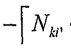
的资源两个 PRB (即, PRB5和 PRB6), 以供这三个扇区 1的中继借用。 The resources of the two PRBs (ie, PRB5 and PRB6) are borrowed for the relay of these three sectors.
至此, eNB3通过与其相邻的三个 eNB进行协调, 完成了对该 eNB3中一个扇区 的处理。 So far, the eNB 3 completes the processing of one sector in the eNB 3 by coordinating with three eNBs adjacent thereto.
eNB3还可以对其扇区 1和 2分别进行上述处理。 The eNB 3 can also perform the above processing for its sectors 1 and 2, respectively.
图 8a和 8b示出了在图 2所示帧结构的情况下根据本发明的实施例的动态 ICIC 方案的另一资源分配。 如图 8a和 8b所示, 例如, 如果扇区 1过载, 则判定该扇区 1 周围的三个扇区 0是否都释放了共同的 PRB, 以及该扇区 1周围的三个扇区 2是否也 释放了共同的 PRB。 在本实施例中, 假定三个扇区 0都释放了共同的 PRB6, 三个扇 区 2都释放了共同的 PRB13和 14, 则扇区 1借用 PRB 6以及 PRB13和 14。这样, 资 源分配从图 8a初始状态变成了图 8b的状态。 类似地, 可以对扇区 2进行相应的计算 和判定以协调资源分配。 Figures 8a and 8b illustrate another resource allocation for a dynamic ICIC scheme in accordance with an embodiment of the present invention in the case of the frame structure shown in Figure 2. As shown in Figures 8a and 8b, for example, if sector 1 is overloaded, it is determined whether three sectors 0 around the sector 1 have released a common PRB, and whether three sectors 2 around the sector 1 are A common PRB is also released. In the present embodiment, it is assumed that all three sectors 0 have released a common PRB6, and three sectors 2 have released a common PRB 13 and 14, and sector 1 borrows PRB 6 and PRBs 13 and 14. Thus, the resource allocation changes from the initial state of Fig. 8a to the state of Fig. 8b. Similarly, sector 2 can be subjected to corresponding calculations and decisions to coordinate resource allocation.
通过与 eNB3周围的 6个 eNB协调, eNB3可以实现对该 eNB3的三个扇区的处 理。 这样, 每个 eNB都进行与 eNB3相同的处理, 从而每个 eNB都不断地与其相邻 的 6个 eNB进行协调, 以动态地为各自的扇区中的中继 UE分配资源。 By coordinating with the six eNBs around eNB3, eNB3 can implement processing of the three sectors of eNB3. Thus, each eNB performs the same processing as eNB3, so that each eNB constantly coordinates with its neighboring 6 eNBs to dynamically allocate resources for relay UEs in the respective sectors.
下面的表 1给出了在无线蜂窝系统中利用本发明的方法和设备进行仿真时所釆用 的参数。 Table 1 below gives the parameters used in the simulation of the wireless cellular system using the method and apparatus of the present invention.
表 1 Table 1
参数 值 Parameter value
蜂窝布局 釆用环绕(wrap around) 的六角形布局, 7个基站 eNodeB, 每个基 站 eNodeB有 3个小区 Cellular layout 六角 wrap around hexagonal layout, 7 base stations eNodeB, 3 base stations per base station eNodeB
系统带宽 10 MHz, 下行链路 System bandwidth 10 MHz, downlink
ISD( Inter-site 500 m (3GPP Case 1 ) distance, 基站 ISD (Inter-site 500 m (3GPP Case 1 ) Distance, base station
间的距离) Distance between)
基站 eNodeB 功 46 dBm 中继 RN Tx功率 30 dBm Base station eNodeB work 46 dBm relay RN Tx power 30 dBm
每个扇区的中继 2 Relay for each sector 2
RN数目 Number of RNs
每个扇区的用户 25 User for each sector 25
终端 UE数目 Number of terminals
调度策略 比例公平调度 Scheduling strategy proportional fair scheduling
下行链路 HARQ 具有 CC (Chasing Combing, Chase合并) 的异步 國、 最大三次 重传、 以及中继网络中的逐跳 HARQ Downlink HARQ has CC (Chasing Combing, Chase merge) asynchronous state, maximum triple retransmission, and hop-by-hop HARQ in the relay network
信道模型 针对 3GPP case 1的宏小区的高频 SCM信道模型 Channel model High frequency SCM channel model for macro cell of 3GPP case 1
基站 eNodeB 天 具有在 3GPP TS 36. 814 VI. 5. 1中定义的天线模式的 1根发射天线 Base station eNodeB Day 1 transmit antenna with antenna pattern defined in 3GPP TS 36. 814 VI.5.1
^继 RN天线配 具有在 3GPP TS 36. 814 VI. 5. 1中定义的天线模式的 1根发射天线 和 2根接收天线 ^ Following the RN antenna with 1 transmit antenna and 2 receive antennas with antenna mode defined in 3GPP TS 36. 814 VI.5.1
用户终端 UE 天 2根接收天线 (0 dBi天线增益、 全向) 下行链路接收机 MRC (最大合并比) User terminal UE day 2 receive antennas (0 dBi antenna gain, omnidirectional) downlink receiver MRC (maximum merge ratio)
类型 Types of
控制信道开销、 LTE : L=3个符号 或者 DL CCH, , 针对解调参考信号的开销 ACK等 Control channel overhead, LTE: L = 3 symbols or DL CCH, , overhead ACK for demodulation reference signals, etc.
L=Prob (R)PLin。 (R) + [1-Prob (R)JP (R), 对于 2GHz, ^?以 km为单 位 L=Prob (R)PL in . (R) + [1-Prob (R)JP (R), for 2GHz, ^? In km
穿透损失 20dB Penetration loss 20dB
路径 PLLJR) = 103. 4+24. 21ogl0 (R) Path PL L JR) = 103. 4+24. 21ogl0 (R)
eNodeB eNodeB
损耗 Loss
至 UE PL s (R)- 131. 1+42. 81oglO (R) To UE PL s (R)- 131. 1+42. 81oglO (R)
模型 Model
Case 1: Case 1:
Prob (R) =min (0. 018/R, l)*(l-exp (-R/0. 063) ) +exp (-R/0. 063) Case 3: Prob (R) =exp (- (R_0. 01)/1. 0) Prob (R) = min (0. 018/R, l)*(l-exp (-R/0. 063) ) +exp (-R/0. 063) Case 3: Prob (R) =exp (- (R_0. 01)/1. 0)
L=Proh (R)PLin (R) + [1-Prob (R) JPL (R) -B, 对于 2GHz, 以 km为 单位, 其中, L=Proh (R)PL in (R) + [1-Prob (R) JPL (R) -B, for 2GHz, in km, where
PLLos (R) =100. 7+23. SloglO (R) PL Los (R) = 100. 7+23. SloglO (R)
eNodeB eNodeB
至 RN PL (R)= 125. 2+36. 31oglO(R) To RN PL (R)= 125. 2+36. 31oglO(R)
Prob ^基于 ITU模型: Case 1: Prob ^ is based on the ITU model: Case 1:
Prob (R) =min (0. 018/R, 1)* (卜 exp (-R/0. 072) ) +exp (~R/0. 072) Prob (R) = min (0. 018/R, 1)* (b exp (-R/0. 072) ) +exp (~R/0. 072)
Case 3 : Prob (R) ^exp (- (R-O. 01)/1. 15) Case 3 : Prob (R) ^exp (- (R-O. 01)/1. 15)
其中, 对于本小区的 RN, B=5dB; 其他小区的 RN, B=OdB Wherein, for the RN of the cell, B=5dB; RN of other cells, B=OdB
L=Prob (R) PL L,OS (R) +[l-Prob (R)]PL NuLiOS (R) , 对于 2GHz, 以 km为单 位, 其中L=Prob (R) PL L, OS (R) + [l-Prob (R)] PL N u L i OS (R) , for 2 GHz, in km, where

PLms (R) ^145. 4+37. 51oglO (R) ' PL ms (R) ^145. 4+37. 51oglO (R) '
RN至 UE RN to UE
Case 1: Case 1:
Prob (R) =0. 5-min (0. 5, 5exp (- 0. 156/R)) +min (0. 5, 5exp (- R/0. 03)) Case 3: Prob (R) =0. 5-min (0. 5, 5exp (- 0. 156/R)) +min (0. 5, 5exp (- R/0. 03)) Case 3:
Prob (R)=0. 5-min (0. 5, 3exp (~0. 3/R)) +min (0. 5, 3exp (-R/0. 095)) 下面的表 2给出了基于表 1的参数配置的仿真结果。 Prob (R)=0. 5-min (0. 5, 3exp (~0. 3/R)) +min (0. 5, 3exp (-R/0. 095)) Table 2 below gives the basis The simulation results of the parameter configuration of Table 1.
表 2 Table 2

在仿真过程中, 将 UE的分布设置为不均勾的, 并且针对每个时间周期该分布是 随机地变化的。 从仿真结果可以看出, 釆用本发明实施例所提出的方法, 小区平均和 小区边缘频谱效率都得到了提高。 During the simulation, the distribution of the UE is set to be non-uniform, and the distribution varies randomly for each time period. It can be seen from the simulation results that the cell average and cell edge spectral efficiency are improved by the method proposed by the embodiment of the present invention.
图 9示出了在无线蜂窝系统中本发明的方法和设备的性能评估。 从图 9中可以看 出, 与传统的静态 ICIC方案相比, 本发明实施例所提出的动态 ICIC方案在性能方面 有了很大提高。 Figure 9 illustrates performance evaluation of the method and apparatus of the present invention in a wireless cellular system. It can be seen from Fig. 9 that the dynamic ICIC scheme proposed by the embodiment of the present invention has greatly improved in performance compared with the conventional static ICIC scheme.
综上所述, 通过根据中继 UE的分布情况来动态地协调为中继 UE分配的资源, 减少了由于中继 UE分布不均匀或者由于中继 UE的移动而导致的资源浪费, 极大地 提高了频谱使用效率。 In summary, by dynamically coordinating the resources allocated to the relay UE according to the distribution of the relay UE, the resource waste caused by the uneven distribution of the relay UE or the movement of the relay UE is greatly improved. The efficiency of spectrum use.
本领域技术人员应该很容易认识到,可以通过编程,利用计算机来实现上述方法 的不同步骤。 在此, 一些实施方式同样包括机器可读或计算机可读的程序存储设备 (如, 数字数据存储介质) 以及编码机器可执行或计算机可执行的程序指令, 其中, 该指令执行上述方法的一些或全部步骤。 例如, 程序存储设备可以是数字存储器、 磁 存储介质 (如磁盘和磁带)、 硬件或光可读数字数据存储介质。 实施方式同样包括执 行存储介质上记录的程序以执行上述方法的所述步骤的计算机。 Those skilled in the art will readily recognize that the various steps of the above methods can be implemented by programming using a computer. Herein, some embodiments also include a program storage device (eg, a digital data storage medium) that is readable by a machine or a computer, and program instructions executable by the machine or executable by the computer, wherein The instruction performs some or all of the steps of the above method. For example, the program storage device can be a digital memory, a magnetic storage medium (such as a magnetic disk and magnetic tape), a hardware or an optically readable digital data storage medium. Embodiments also include a computer that executes a program recorded on a storage medium to perform the steps of the above method.
上面结和附图所做的描述只是为了说明本发明而示例性给出的。本领域技术人员 可以理解, 能够基于上面所描述的本发明的原理提出不同的结构, 虽然这些不同的结 构未在此处明确描述或示出, 但体现了本发明的原理并包括在其精神和范围之内。 此 外, 所有此处提到的示例明确地主要只用于教学目的以帮助读者理解本发明的原理以 及发明人所贡献的促进本领域的构思, 并应被解释为不是对这些特定提到的示例和条 件的限制。 此外, 此处所有提到本发明的原则、 方面和实施方式的陈述及其特定的示 例包含其等同物在内。 The descriptions of the above and the drawings are merely illustrative for the purpose of illustrating the invention. It will be appreciated by those skilled in the art that the present invention may be practiced in various embodiments, and the various structures are not described or illustrated herein. Within the scope. In addition, all of the examples mentioned herein are explicitly used primarily for teaching purposes to assist the reader in understanding the principles of the present invention and the concepts promoted by the inventors, and should be construed as not to the specific examples. And conditional restrictions. In addition, all statements herein reciting principles, aspects, and embodiments of the invention, as well as the specific examples thereof,
Claims


Priority Applications (7)
| Application Number | Priority Date | Filing Date | Title |
|---|---|---|---|
| BR112012020098A BR112012020098A2 (en) | 2010-02-12 | 2010-02-12 | device and method for coordinating inter-cell interference in relay-assisted cellular networks. |
| KR1020127023593A KR20120116016A (en) | 2010-02-12 | 2010-02-12 | Equipment and method for inter-cell interference coordination in relay auxiliary cellular network |
| JP2012552223A JP5749742B2 (en) | 2010-02-12 | 2010-02-12 | Device and method for inter-cell interference coordination in a relay-assisted cellular network |
| EP10845438.0A EP2536192A4 (en) | 2010-02-12 | 2010-02-12 | Equipment and method for inter-cell interference coordination in relay auxiliary cellular network |
| PCT/CN2010/000204 WO2011097764A1 (en) | 2010-02-12 | 2010-02-12 | Equipment and method for inter-cell interference coordination in relay auxiliary cellular network |
| US13/578,202 US9107068B2 (en) | 2010-02-12 | 2010-02-12 | Device and method for inter-cell interference coordination in relay-assistant cellular network |
| CN201080055112.7A CN102652441B (en) | 2010-02-12 | 2010-02-12 | Apparatus and method for inter-cell interference coordination in relay-assisted cellular network |
Applications Claiming Priority (1)
| Application Number | Priority Date | Filing Date | Title |
|---|---|---|---|
| PCT/CN2010/000204 WO2011097764A1 (en) | 2010-02-12 | 2010-02-12 | Equipment and method for inter-cell interference coordination in relay auxiliary cellular network |
Publications (1)
| Publication Number | Publication Date |
|---|---|
| WO2011097764A1 true WO2011097764A1 (en) | 2011-08-18 |
Family
ID=44367122
Family Applications (1)
| Application Number | Title | Priority Date | Filing Date |
|---|---|---|---|
| PCT/CN2010/000204 Ceased WO2011097764A1 (en) | 2010-02-12 | 2010-02-12 | Equipment and method for inter-cell interference coordination in relay auxiliary cellular network |
Country Status (7)
| Country | Link |
|---|---|
| US (1) | US9107068B2 (en) |
| EP (1) | EP2536192A4 (en) |
| JP (1) | JP5749742B2 (en) |
| KR (1) | KR20120116016A (en) |
| CN (1) | CN102652441B (en) |
| BR (1) | BR112012020098A2 (en) |
| WO (1) | WO2011097764A1 (en) |
Cited By (3)
| Publication number | Priority date | Publication date | Assignee | Title |
|---|---|---|---|---|
| WO2013108116A1 (en) * | 2012-01-19 | 2013-07-25 | Telefonaktiebolaget Lm Ericsson (Publ) | Fractional frequency re-use and beamforming in relay nodes of a heterogeneous network |
| JP2015534782A (en) * | 2012-10-05 | 2015-12-03 | テレフオンアクチーボラゲット エル エム エリクソン(パブル) | Mitigating interference from mobile relay nodes to heterogeneous networks |
| WO2022143467A1 (en) * | 2020-12-28 | 2022-07-07 | 索尼集团公司 | Electronic device and method in wireless communication system |
Families Citing this family (2)
| Publication number | Priority date | Publication date | Assignee | Title |
|---|---|---|---|---|
| CN104066093B (en) * | 2013-03-18 | 2018-03-23 | 财团法人工业技术研究院 | Interference management method, anchor point equipment, base station and system of wireless communication system |
| CN103997742B (en) * | 2014-05-07 | 2017-06-27 | 西安交通大学 | Relay selection strategy based on load in a kind of LTE A relayings Cellular Networks |
Citations (6)
| Publication number | Priority date | Publication date | Assignee | Title |
|---|---|---|---|---|
| EP1662825A1 (en) * | 2004-11-24 | 2006-05-31 | Samsung Electronics Co., Ltd. | Method for allocating resources in a multicarrier system and transmission apparatus using same |
| CN101146343A (en) * | 2006-09-13 | 2008-03-19 | 联想(北京)有限公司 | A bandwidth resource allocation method and device in mobile communication system |
| US20080194267A1 (en) * | 2007-02-13 | 2008-08-14 | Samsung Electronics Co., Ltd. | Method of assigning carrier for mitigating inter-cell interference in fixed relay based communication system |
| CN101272549A (en) * | 2008-05-09 | 2008-09-24 | 中兴通讯股份有限公司 | Relay network overload indication reporting method |
| CN101547480A (en) * | 2008-03-24 | 2009-09-30 | 中兴通讯股份有限公司 | Resource allocation control method and resource allocation control device |
| CN101568123A (en) * | 2008-04-21 | 2009-10-28 | 中国移动通信集团公司 | Method and system for data carrying in relay system |
Family Cites Families (12)
| Publication number | Priority date | Publication date | Assignee | Title |
|---|---|---|---|---|
| JP2000138965A (en) | 1998-11-04 | 2000-05-16 | Nec Saitama Ltd | Radio base station, its control method and control program recording medium |
| JP4014950B2 (en) * | 2002-06-26 | 2007-11-28 | 三菱電機株式会社 | Wireless communication system and communication method |
| WO2005041348A2 (en) * | 2003-10-24 | 2005-05-06 | Celletra Ltd. | Distributed cell balancing |
| TWI452884B (en) * | 2006-11-01 | 2014-09-11 | Qualcomm Inc | Sub-band dependent resource management |
| KR20100005227A (en) * | 2007-05-31 | 2010-01-14 | 닛본 덴끼 가부시끼가이샤 | Base station, radio communication system, band control method |
| JP2011505088A (en) * | 2007-11-27 | 2011-02-17 | 中▲興▼通▲訊▼股▲ふん▼有限公司 | Downlink transmission system and method for borrowing spectrum resources and channel resources of adjacent cells |
| US8229449B2 (en) | 2007-12-21 | 2012-07-24 | Samsung Electronics Co., Ltd. | Method and system for allocating subcarrier frequency resources for a relay enhanced cellular communication system |
| KR100973587B1 (en) | 2008-01-02 | 2010-08-02 | 한국과학기술원 | Resource Request and Allocation Method Using CDM Codes in Multi-hop Orthogonal Frequency Division Multiple Access-Based Wireless Access Communication Systems |
| KR101532436B1 (en) | 2008-02-29 | 2015-07-01 | 엘지전자 주식회사 | Resource allocation method for intercell interference adjustment |
| US7962091B2 (en) * | 2008-03-14 | 2011-06-14 | Intel Corporation | Resource management and interference mitigation techniques for relay-based wireless networks |
| US8355734B2 (en) * | 2008-08-07 | 2013-01-15 | Apple Inc. | Wireless system |
| US8208937B2 (en) * | 2009-06-12 | 2012-06-26 | Futurewei Technologies, Inc. | System and method for uplink inter cell interference coordination in a wireless access system |
-
2010
- 2010-02-12 WO PCT/CN2010/000204 patent/WO2011097764A1/en not_active Ceased
- 2010-02-12 BR BR112012020098A patent/BR112012020098A2/en not_active IP Right Cessation
- 2010-02-12 KR KR1020127023593A patent/KR20120116016A/en not_active Ceased
- 2010-02-12 US US13/578,202 patent/US9107068B2/en not_active Expired - Fee Related
- 2010-02-12 EP EP10845438.0A patent/EP2536192A4/en not_active Withdrawn
- 2010-02-12 CN CN201080055112.7A patent/CN102652441B/en active Active
- 2010-02-12 JP JP2012552223A patent/JP5749742B2/en not_active Expired - Fee Related
Patent Citations (6)
| Publication number | Priority date | Publication date | Assignee | Title |
|---|---|---|---|---|
| EP1662825A1 (en) * | 2004-11-24 | 2006-05-31 | Samsung Electronics Co., Ltd. | Method for allocating resources in a multicarrier system and transmission apparatus using same |
| CN101146343A (en) * | 2006-09-13 | 2008-03-19 | 联想(北京)有限公司 | A bandwidth resource allocation method and device in mobile communication system |
| US20080194267A1 (en) * | 2007-02-13 | 2008-08-14 | Samsung Electronics Co., Ltd. | Method of assigning carrier for mitigating inter-cell interference in fixed relay based communication system |
| CN101547480A (en) * | 2008-03-24 | 2009-09-30 | 中兴通讯股份有限公司 | Resource allocation control method and resource allocation control device |
| CN101568123A (en) * | 2008-04-21 | 2009-10-28 | 中国移动通信集团公司 | Method and system for data carrying in relay system |
| CN101272549A (en) * | 2008-05-09 | 2008-09-24 | 中兴通讯股份有限公司 | Relay network overload indication reporting method |
Cited By (4)
| Publication number | Priority date | Publication date | Assignee | Title |
|---|---|---|---|---|
| WO2013108116A1 (en) * | 2012-01-19 | 2013-07-25 | Telefonaktiebolaget Lm Ericsson (Publ) | Fractional frequency re-use and beamforming in relay nodes of a heterogeneous network |
| US9264912B2 (en) | 2012-01-19 | 2016-02-16 | Telefonaktiebolaget L M Ericsson (Publ) | Fractional frequency re-use and beamforming in relay nodes of a heterogeneous network |
| JP2015534782A (en) * | 2012-10-05 | 2015-12-03 | テレフオンアクチーボラゲット エル エム エリクソン(パブル) | Mitigating interference from mobile relay nodes to heterogeneous networks |
| WO2022143467A1 (en) * | 2020-12-28 | 2022-07-07 | 索尼集团公司 | Electronic device and method in wireless communication system |
Also Published As
| Publication number | Publication date |
|---|---|
| US20120315840A1 (en) | 2012-12-13 |
| EP2536192A4 (en) | 2014-11-26 |
| BR112012020098A2 (en) | 2018-03-20 |
| JP5749742B2 (en) | 2015-07-15 |
| CN102652441A (en) | 2012-08-29 |
| EP2536192A1 (en) | 2012-12-19 |
| US9107068B2 (en) | 2015-08-11 |
| JP2013520040A (en) | 2013-05-30 |
| CN102652441B (en) | 2015-03-11 |
| KR20120116016A (en) | 2012-10-19 |
Similar Documents
| Publication | Publication Date | Title |
|---|---|---|
| JP7088146B2 (en) | Communication systems, radio base stations, and control methods for radio base stations | |
| Zhang et al. | Coexistence of Wi-Fi and heterogeneous small cell networks sharing unlicensed spectrum | |
| US9113451B2 (en) | Radio communication system, base station, and control method thereof | |
| JP2011244435A (en) | Control channel interference mitigation | |
| JP5512476B2 (en) | Inter-cell interference coordination method and base station | |
| WO2011129447A1 (en) | Wireless communication system, high-power base station, low-power base station, and communication control method | |
| US9326151B2 (en) | Methods and arrangements for a coordination of frequency band selections for interfering uplink transmissions in a cellular network | |
| WO2011097764A1 (en) | Equipment and method for inter-cell interference coordination in relay auxiliary cellular network | |
| EP2816832B1 (en) | Heterogeneous network | |
| KR20150053796A (en) | Altruistic scheduling in heterogeneous wireless networks | |
| EP2905994B1 (en) | Resource allocation method for shared base station | |
| Fujisawa et al. | Personal-cell scheme using adaptive control CRE for multicarrier HetNets | |
| CN102668659B (en) | Method and device for inter-cell interference coordination in relay-assisted cellular system | |
| CN102696250B (en) | Method and device for allocating frequency bands by using frequency reuse | |
| Wang et al. | Load balance based dynamic inter-cell interference coordination for relay enhanced cellular network | |
| Chhetri et al. | Intercell interference mitigation in lte-advanced heterogeneous network | |
| Hasan et al. | Performance analysis of interference coordination techniques in heterogeneous network | |
| KR101463534B1 (en) | Method of radio resource allocation using channel sensing and frequency reuse for cognitive femtocells and apparatus for performing the same | |
| WO2012110309A1 (en) | A mobile and a base station transceiver, methods and computer programs for providing measurement configuration and measurement result | |
| CN102726084B (en) | Frequency reuse method and device | |
| Yu et al. | A novel semi-static interference coordination scheme for LTE uplink | |
| KR20140077304A (en) | Method of channel allocation for mitigating interference inside basestation cell and inter basestation cell | |
| Wang et al. | A UE-interfering-area based inter-cell interference Coordination scheme in SC-FDMA uplinks | |
| LAWAL et al. | FRACTIONAL FREQUENCY REUSE TECHNIQUES IN CELLULAR NETWORK RESOURCE ALLOCATION: A LITERATURE SURVEY | |
| Salem et al. | Context-aware handoff selection algorithm in femtocell networks |
Legal Events
| Date | Code | Title | Description |
|---|---|---|---|
| WWE | Wipo information: entry into national phase |
Ref document number: 201080055112.7 Country of ref document: CN |
|
| 121 | Ep: the epo has been informed by wipo that ep was designated in this application |
Ref document number: 10845438 Country of ref document: EP Kind code of ref document: A1 |
|
| WWE | Wipo information: entry into national phase |
Ref document number: 13578202 Country of ref document: US |
|
| WWE | Wipo information: entry into national phase |
Ref document number: 2012552223 Country of ref document: JP |
|
| NENP | Non-entry into the national phase |
Ref country code: DE |
|
| REEP | Request for entry into the european phase |
Ref document number: 2010845438 Country of ref document: EP |
|
| WWE | Wipo information: entry into national phase |
Ref document number: 2010845438 Country of ref document: EP |
|
| WWE | Wipo information: entry into national phase |
Ref document number: 7702/CHENP/2012 Country of ref document: IN |
|
| ENP | Entry into the national phase |
Ref document number: 20127023593 Country of ref document: KR Kind code of ref document: A |
|
| REG | Reference to national code |
Ref country code: BR Ref legal event code: B01A Ref document number: 112012020098 Country of ref document: BR |
|
| ENP | Entry into the national phase |
Ref document number: 112012020098 Country of ref document: BR Kind code of ref document: A2 Effective date: 20120810 |