WO2010113719A1 - Multiple air conditioner - Google Patents
Multiple air conditioner Download PDFInfo
- Publication number
- WO2010113719A1 WO2010113719A1 PCT/JP2010/055063 JP2010055063W WO2010113719A1 WO 2010113719 A1 WO2010113719 A1 WO 2010113719A1 JP 2010055063 W JP2010055063 W JP 2010055063W WO 2010113719 A1 WO2010113719 A1 WO 2010113719A1
- Authority
- WO
- WIPO (PCT)
- Prior art keywords
- electromagnetic
- outdoor unit
- valve
- air conditioner
- capillary tube
- Prior art date
- Legal status (The legal status is an assumption and is not a legal conclusion. Google has not performed a legal analysis and makes no representation as to the accuracy of the status listed.)
- Ceased
Links
Images


Classifications
-
- F—MECHANICAL ENGINEERING; LIGHTING; HEATING; WEAPONS; BLASTING
- F25—REFRIGERATION OR COOLING; COMBINED HEATING AND REFRIGERATION SYSTEMS; HEAT PUMP SYSTEMS; MANUFACTURE OR STORAGE OF ICE; LIQUEFACTION SOLIDIFICATION OF GASES
- F25B—REFRIGERATION MACHINES, PLANTS OR SYSTEMS; COMBINED HEATING AND REFRIGERATION SYSTEMS; HEAT PUMP SYSTEMS
- F25B13/00—Compression machines, plants or systems, with reversible cycle
-
- F—MECHANICAL ENGINEERING; LIGHTING; HEATING; WEAPONS; BLASTING
- F25—REFRIGERATION OR COOLING; COMBINED HEATING AND REFRIGERATION SYSTEMS; HEAT PUMP SYSTEMS; MANUFACTURE OR STORAGE OF ICE; LIQUEFACTION SOLIDIFICATION OF GASES
- F25B—REFRIGERATION MACHINES, PLANTS OR SYSTEMS; COMBINED HEATING AND REFRIGERATION SYSTEMS; HEAT PUMP SYSTEMS
- F25B41/00—Fluid-circulation arrangements
- F25B41/30—Expansion means; Dispositions thereof
- F25B41/37—Capillary tubes
-
- F—MECHANICAL ENGINEERING; LIGHTING; HEATING; WEAPONS; BLASTING
- F25—REFRIGERATION OR COOLING; COMBINED HEATING AND REFRIGERATION SYSTEMS; HEAT PUMP SYSTEMS; MANUFACTURE OR STORAGE OF ICE; LIQUEFACTION SOLIDIFICATION OF GASES
- F25B—REFRIGERATION MACHINES, PLANTS OR SYSTEMS; COMBINED HEATING AND REFRIGERATION SYSTEMS; HEAT PUMP SYSTEMS
- F25B41/00—Fluid-circulation arrangements
- F25B41/30—Expansion means; Dispositions thereof
- F25B41/385—Dispositions with two or more expansion means arranged in parallel on a refrigerant line leading to the same evaporator
-
- F—MECHANICAL ENGINEERING; LIGHTING; HEATING; WEAPONS; BLASTING
- F25—REFRIGERATION OR COOLING; COMBINED HEATING AND REFRIGERATION SYSTEMS; HEAT PUMP SYSTEMS; MANUFACTURE OR STORAGE OF ICE; LIQUEFACTION SOLIDIFICATION OF GASES
- F25B—REFRIGERATION MACHINES, PLANTS OR SYSTEMS; COMBINED HEATING AND REFRIGERATION SYSTEMS; HEAT PUMP SYSTEMS
- F25B41/00—Fluid-circulation arrangements
- F25B41/30—Expansion means; Dispositions thereof
- F25B41/39—Dispositions with two or more expansion means arranged in series, i.e. multi-stage expansion, on a refrigerant line leading to the same evaporator
-
- F—MECHANICAL ENGINEERING; LIGHTING; HEATING; WEAPONS; BLASTING
- F24—HEATING; RANGES; VENTILATING
- F24F—AIR-CONDITIONING; AIR-HUMIDIFICATION; VENTILATION; USE OF AIR CURRENTS FOR SCREENING
- F24F11/00—Control or safety arrangements
- F24F11/70—Control systems characterised by their outputs; Constructional details thereof
- F24F11/80—Control systems characterised by their outputs; Constructional details thereof for controlling the temperature of the supplied air
- F24F11/83—Control systems characterised by their outputs; Constructional details thereof for controlling the temperature of the supplied air by controlling the supply of heat-exchange fluids to heat-exchangers
- F24F11/84—Control systems characterised by their outputs; Constructional details thereof for controlling the temperature of the supplied air by controlling the supply of heat-exchange fluids to heat-exchangers using valves
-
- F—MECHANICAL ENGINEERING; LIGHTING; HEATING; WEAPONS; BLASTING
- F25—REFRIGERATION OR COOLING; COMBINED HEATING AND REFRIGERATION SYSTEMS; HEAT PUMP SYSTEMS; MANUFACTURE OR STORAGE OF ICE; LIQUEFACTION SOLIDIFICATION OF GASES
- F25B—REFRIGERATION MACHINES, PLANTS OR SYSTEMS; COMBINED HEATING AND REFRIGERATION SYSTEMS; HEAT PUMP SYSTEMS
- F25B2313/00—Compression machines, plants or systems with reversible cycle not otherwise provided for
- F25B2313/005—Outdoor unit expansion valves
-
- F—MECHANICAL ENGINEERING; LIGHTING; HEATING; WEAPONS; BLASTING
- F25—REFRIGERATION OR COOLING; COMBINED HEATING AND REFRIGERATION SYSTEMS; HEAT PUMP SYSTEMS; MANUFACTURE OR STORAGE OF ICE; LIQUEFACTION SOLIDIFICATION OF GASES
- F25B—REFRIGERATION MACHINES, PLANTS OR SYSTEMS; COMBINED HEATING AND REFRIGERATION SYSTEMS; HEAT PUMP SYSTEMS
- F25B2313/00—Compression machines, plants or systems with reversible cycle not otherwise provided for
- F25B2313/006—Compression machines, plants or systems with reversible cycle not otherwise provided for two pipes connecting the outdoor side to the indoor side with multiple indoor units
-
- F—MECHANICAL ENGINEERING; LIGHTING; HEATING; WEAPONS; BLASTING
- F25—REFRIGERATION OR COOLING; COMBINED HEATING AND REFRIGERATION SYSTEMS; HEAT PUMP SYSTEMS; MANUFACTURE OR STORAGE OF ICE; LIQUEFACTION SOLIDIFICATION OF GASES
- F25B—REFRIGERATION MACHINES, PLANTS OR SYSTEMS; COMBINED HEATING AND REFRIGERATION SYSTEMS; HEAT PUMP SYSTEMS
- F25B2313/00—Compression machines, plants or systems with reversible cycle not otherwise provided for
- F25B2313/023—Compression machines, plants or systems with reversible cycle not otherwise provided for using multiple indoor units
- F25B2313/0233—Compression machines, plants or systems with reversible cycle not otherwise provided for using multiple indoor units in parallel arrangements
-
- F—MECHANICAL ENGINEERING; LIGHTING; HEATING; WEAPONS; BLASTING
- F25—REFRIGERATION OR COOLING; COMBINED HEATING AND REFRIGERATION SYSTEMS; HEAT PUMP SYSTEMS; MANUFACTURE OR STORAGE OF ICE; LIQUEFACTION SOLIDIFICATION OF GASES
- F25B—REFRIGERATION MACHINES, PLANTS OR SYSTEMS; COMBINED HEATING AND REFRIGERATION SYSTEMS; HEAT PUMP SYSTEMS
- F25B2313/00—Compression machines, plants or systems with reversible cycle not otherwise provided for
- F25B2313/027—Compression machines, plants or systems with reversible cycle not otherwise provided for characterised by the reversing means
- F25B2313/02741—Compression machines, plants or systems with reversible cycle not otherwise provided for characterised by the reversing means using one four-way valve
-
- F—MECHANICAL ENGINEERING; LIGHTING; HEATING; WEAPONS; BLASTING
- F25—REFRIGERATION OR COOLING; COMBINED HEATING AND REFRIGERATION SYSTEMS; HEAT PUMP SYSTEMS; MANUFACTURE OR STORAGE OF ICE; LIQUEFACTION SOLIDIFICATION OF GASES
- F25B—REFRIGERATION MACHINES, PLANTS OR SYSTEMS; COMBINED HEATING AND REFRIGERATION SYSTEMS; HEAT PUMP SYSTEMS
- F25B2500/00—Problems to be solved
- F25B2500/01—Geometry problems, e.g. for reducing size
-
- F—MECHANICAL ENGINEERING; LIGHTING; HEATING; WEAPONS; BLASTING
- F25—REFRIGERATION OR COOLING; COMBINED HEATING AND REFRIGERATION SYSTEMS; HEAT PUMP SYSTEMS; MANUFACTURE OR STORAGE OF ICE; LIQUEFACTION SOLIDIFICATION OF GASES
- F25B—REFRIGERATION MACHINES, PLANTS OR SYSTEMS; COMBINED HEATING AND REFRIGERATION SYSTEMS; HEAT PUMP SYSTEMS
- F25B2500/00—Problems to be solved
- F25B2500/06—Damage
-
- F—MECHANICAL ENGINEERING; LIGHTING; HEATING; WEAPONS; BLASTING
- F25—REFRIGERATION OR COOLING; COMBINED HEATING AND REFRIGERATION SYSTEMS; HEAT PUMP SYSTEMS; MANUFACTURE OR STORAGE OF ICE; LIQUEFACTION SOLIDIFICATION OF GASES
- F25B—REFRIGERATION MACHINES, PLANTS OR SYSTEMS; COMBINED HEATING AND REFRIGERATION SYSTEMS; HEAT PUMP SYSTEMS
- F25B2600/00—Control issues
- F25B2600/25—Control of valves
- F25B2600/2513—Expansion valves
-
- F—MECHANICAL ENGINEERING; LIGHTING; HEATING; WEAPONS; BLASTING
- F25—REFRIGERATION OR COOLING; COMBINED HEATING AND REFRIGERATION SYSTEMS; HEAT PUMP SYSTEMS; MANUFACTURE OR STORAGE OF ICE; LIQUEFACTION SOLIDIFICATION OF GASES
- F25B—REFRIGERATION MACHINES, PLANTS OR SYSTEMS; COMBINED HEATING AND REFRIGERATION SYSTEMS; HEAT PUMP SYSTEMS
- F25B2600/00—Control issues
- F25B2600/25—Control of valves
- F25B2600/2519—On-off valves
-
- F—MECHANICAL ENGINEERING; LIGHTING; HEATING; WEAPONS; BLASTING
- F25—REFRIGERATION OR COOLING; COMBINED HEATING AND REFRIGERATION SYSTEMS; HEAT PUMP SYSTEMS; MANUFACTURE OR STORAGE OF ICE; LIQUEFACTION SOLIDIFICATION OF GASES
- F25B—REFRIGERATION MACHINES, PLANTS OR SYSTEMS; COMBINED HEATING AND REFRIGERATION SYSTEMS; HEAT PUMP SYSTEMS
- F25B2700/00—Sensing or detecting of parameters; Sensors therefor
- F25B2700/19—Pressures
- F25B2700/191—Pressures near an expansion valve
Definitions
- the present invention relates to a multi-type air conditioner, and more particularly to a multi-type air conditioner in which a head difference of liquid refrigerant occurs between an outdoor unit and an indoor unit installed below the outdoor unit. .
- an electronic expansion valve is provided in front (inlet) of the indoor heat exchanger.
- An arrangement is known (for example, see Patent Document 1).
- the present invention has been made in view of the above circumstances, and can reduce the liquid head pressure acting on the electronic expansion valve disposed in front (inlet) of the indoor heat exchanger, resulting in poor opening and closing of the electronic expansion valve.
- An object is to provide a multi-type air conditioner capable of preventing (operation failure).
- a first aspect of the multi-type air conditioner according to the present invention includes a single outdoor unit and a plurality of indoor units installed below the outdoor unit and connected to the outdoor unit via refrigerant piping.
- a multi-type air conditioner comprising at least two electromagnetic on-off valves and at least two capillary tubes in the vicinity of an outlet of the outdoor unit during cooling operation. And a pressure reducing mechanism in which a capillary tube connected to the electromagnetic on-off valve is arranged in parallel with the refrigerant pipe.
- the second aspect of the multi-type air conditioner according to the present invention includes a single outdoor unit and a plurality of units installed below the outdoor unit and connected to the outdoor unit via refrigerant piping.
- a multi-type air conditioner including three indoor on-off valves and three capillary tubes having different lengths in the vicinity of the outlet of the outdoor unit during cooling operation.
- the length of the capillary tube is such that, for example, all the solenoid on-off valves are opened and all capillary tubes are used. Is set to “1”, and only the longest capillary tube is used by opening only the electromagnetic on-off valve connected to the longest capillary tube (hereinafter referred to as “longest capillary tube”). / 10 ”, the effect of pressure reduction when only the shortest capillary tube is used by opening only the electromagnetic on-off valve connected to the shortest capillary tube (hereinafter referred to as“ shortest capillary tube ”) is“ 6/10 ”.
- the effect of pressure reduction is “7/10”, the intermediate length capillary tube and the shortest capillary tube
- the effect of pressure reduction is “9/10”. That is, the pressure of the liquid refrigerant supplied (guided) from the outdoor unit to the indoor unit can be reduced in several patterns only by changing the combination (pattern) of the open / close solenoid valves. Thereby, the liquid head pressure which acts on the electronic expansion valve arrange
- each of the electromagnetic on-off valves is electrically connected to a controller that individually opens and closes the electromagnetic control valves, and the controller It is more preferable that the electromagnetic on-off valve is configured to open and close based on the refrigerant pressure in the vicinity of the outlet during the cooling operation of the outdoor unit and the rotation speed of the compressor that constitutes the outdoor unit.
- the electromagnetic on-off valve is instantaneously opened and closed based on the refrigerant pressure in the vicinity of the outlet during the cooling operation of the outdoor unit and the rotational speed of the compressor constituting the outdoor unit,
- the liquid head pressure acting on the electronic expansion valve disposed in front of the indoor heat exchanger is maintained at an optimum pressure.
- the liquid head pressure acting on the electronic expansion valve disposed in front (inlet) of the indoor heat exchanger can be reduced, and the opening / closing failure (operation of the electronic expansion valve) It is possible to prevent defects).
- FIG. 1 is a schematic system diagram of a multi-type air conditioner according to an embodiment of the present invention. It is the figure which expanded the principal part of FIG. It is a graph for demonstrating the length of a capillary tube, and the effect of the pressure reduction. It is the graph which visualized the data memorize
- FIG. 1 is a schematic system diagram of a multi-type air conditioner according to the present embodiment
- FIG. 2 is an enlarged view of the main part of FIG. 1
- FIG. 3 is a diagram for explaining the length of a capillary tube and the effect of decompression thereof.
- 4A and 4B are charts visualizing data stored as a database in the controller
- FIG. 4A is a chart when the measured value measured by the high-pressure sensor is higher than a specified value
- FIG. 4B is a high-pressure sensor.
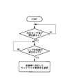
- FIG. 5 is a flowchart for operating the controller when the measured value measured in step 1 is lower than the specified value.
- the multi-type air conditioner 1 includes one outdoor unit 2 and a plurality of (for example, two) indoor units 3.
- the outdoor unit 2 is installed, for example, on the roof of a high-rise building, and includes a compressor 4, a four-way valve 5, an outdoor heat exchanger 6, an outdoor fan (not shown), and a pressure reducing mechanism 7.
- the indoor unit 3 is installed in a living room of a floor (floor), for example, 100 m lower than the rooftop on which the outdoor unit 2 is installed, and includes an indoor heat exchanger (not shown) and an indoor fan (not shown). )).
- the outdoor unit 2 and the indoor unit 3 are connected via a refrigerant pipe 8, and a liquid operation valve 9 is connected in the middle of the refrigerant pipe 8 connected between the decompression mechanism 7 and the indoor unit 3. ing.
- the liquid operation valve 9 is disposed in the vicinity (exit) of the outdoor unit 2, and a high pressure sensor that measures the pressure in the pipe in the middle of the refrigerant pipe 8 connected between the pressure reducing mechanism 7 and the liquid operation valve 9. 10 is attached.
- the high-pressure sensor 10 is electrically connected to a controller 28 described later, and a measurement value (hereinafter referred to as “high-pressure sensor value”) measured by the high-pressure sensor 10 is converted into an electric signal and is then controlled. Is output.
- an electronic expansion valve 11 is connected in the middle of the refrigerant pipe 8 connected between the liquid operation valve 9 and the indoor unit 3.
- An electronic expansion valve (hereinafter referred to as “EEV”) 11 is disposed in the vicinity (inlet) of each indoor unit 3.
- the pressure reducing mechanism 7 includes one check valve 21, a plurality (three in this embodiment) of electromagnetic on-off valves 22, 23, and 24, and a plurality of (in this embodiment) different lengths. 3) capillary tubes 25, 26, and 27.
- a capillary tube 25 is connected to the electromagnetic open / close valve 22
- a capillary tube 26 is connected to the electromagnetic open / close valve 23
- a capillary tube 27 is connected to the electromagnetic open / close valve 24.
- the check valve 21, the electromagnetic on-off valve 22 and the capillary tube 25, the electromagnetic on-off valve 23 and the capillary tube 26, and the electromagnetic on-off valve 24 and the capillary tube 27 are arranged in parallel via the refrigerant pipe 8. Yes.
- the electromagnetic open / close valves 23, 24, 25 are electrically connected to the controller 28, and the opening / closing thereof is controlled by an electric signal output from the controller 28.
- the check valve 21 is attached in a direction that allows a flow from the liquid operation valve 9 to the outdoor heat exchanger 6 and prevents a flow from the outdoor heat exchanger 6 to the liquid operation valve 9.
- the length of the capillary tubes 25, 26, 27 is, for example, the effect of depressurization when all the capillary tubes 25, 26, 27 are used by opening all the electromagnetic on-off valves 22, 23, 24. 1 ”(see column“ 7 ”in FIG. 3), the effect of pressure reduction when only the solenoid valve 22 is opened and only the capillary tube 25 is used is“ 1/10 ”(see column“ 1 ”in FIG. 3). ), Only the electromagnetic on-off valve 23 is opened, and the effect of pressure reduction when only the capillary tube 26 is used is “3/10” (see the column “2” in FIG. 3). The pressure reduction effect when only the tube 27 is used is set to be “6/10” (see the “4” column in FIG. 3).
- the controller 28 stores (accumulates) the database of the charts shown in FIGS. 4A and 4B as a database, and the controller 28 performs electromagnetic on-off valves 22, 23, 24 according to the flowchart shown in FIG. Is opened and closed to adjust the pressure in front of the EEV 11 (inlet). That is, when the high-pressure sensor value measured by the high-pressure sensor 10 is equal to or higher than the specified value, and the compressor speed (the rotational speed of the compressor 4) is equal to or lower than the specified value, the controller 28 controls the controller 28 before EEV11.
- the electromagnetic on-off valves 22, 23, 24 and capillary tubes 25, 26, 27 to be used are selected based on the database stored in the controller 28 so that the pressure at the (inlet) becomes a desired pressure.
- the valves 22, 23 and 24 are opened and closed.
- the high-pressure sensor value measured by the high-pressure sensor 10 is equal to or higher than a specified value, and the compression speed is equal to or lower than the specified value
- the high-pressure sensor value at that time is another specified value (second specified value).
- the electromagnetic on-off valves 22 and 24 are opened and the capillary tubes 25 and 27 are used.
- the high pressure sensor value measured by the high pressure sensor 10 is equal to or higher than the specified value, and the rotational speed of the compressor is equal to or lower than the specified value.
- the high pressure sensor value at that time is another specified value (second specified value). In the case where the rotational speed of the compressor is within the lowest range, only the electromagnetic on-off valve 23 is opened and only the capillary tube 26 is used.
- the lengths of the capillary tubes 25, 26, 27 are set such that, for example, all the electromagnetic on-off valves 22, 23, 24 are opened and all the capillary tubes 25, 26 are opened. , 27 is set to “1”, only the solenoid on / off valve 22 connected to the longest capillary tube 25 is opened, and the pressure reduction effect when only the capillary tube 25 is used is “1 /”.
- the effect of pressure reduction when using only the capillary tube 27 by opening only the electromagnetic on-off valve 24 connected to the shortest capillary tube 27 is“ 6/10 ”, shorter than the capillary tube 25, and the capillary tube 27
- the solenoid on / off valve 23 connected to the longer capillary tube 26 is opened and only the capillary tube 26 is used
- the effect of the reduced pressure is set to be the "3/10”.
- the electromagnetic on-off valves 22 and 23 connected to the capillary tubes 25 and 26 are opened, and the effect of pressure reduction when the capillary tubes 25 and 26 are used is “4/10”, and the capillary tubes 25 and 27 are connected.
- the pressure reduction effect is “7/10”.
- the solenoid valves 23 and 24 connected to the capillary tubes 26 and 27 are opened and the capillaries are opened.
- the effect of pressure reduction when the tubes 26 and 27 are used is “9/10”. That is, the pressure of the liquid refrigerant supplied (guided) from the outdoor unit 2 to the indoor unit 3 can be reduced in several patterns only by changing the combination (pattern) of the open / close solenoid valves 22, 23, 24. .
- positioned in front (inlet) of an indoor heat exchanger can be reduced, and the opening / closing failure (operation failure) of EEV11 can be prevented.
- the electromagnetic opening / closing valves 22, 23, and 24 are electrically connected to a controller 28 that individually opens and closes these electromagnetic control valves 22, 23, and 24, respectively.
- the electromagnetic on-off valves 22, 23, and 24 are configured to open and close based on the refrigerant pressure near the outlet during operation and the rotational speed of the compressor 4 that constitutes the outdoor unit 2. That is, based on the refrigerant pressure in the vicinity of the outlet of the outdoor unit 2 during the cooling operation and the rotational speed of the compressor 4 constituting the outdoor unit 2, the electromagnetic on-off valves 22, 23, and 24 are instantaneously opened and closed, and the indoor heat The liquid head pressure acting on the EEV 11 arranged in front of the exchanger is maintained at an optimum pressure. Thereby, it is possible to prevent an excessive liquid head pressure from acting on the EEV 11 disposed in front of the indoor heat exchanger, and it is possible to more reliably prevent an open / close failure (operation failure) of the EEV 11.
- the present invention is not limited to the above-described embodiments, and various changes and modifications can be made without departing from the gist of the present invention.
- the pressure reducing mechanism 7 including the three electromagnetic opening / closing valves 22, 23, and 24 and the three capillary tubes 25, 26, and 27 having different lengths is described as a specific example. .
- the decompression mechanism 7 includes three electromagnetic on-off valves and three capillary tubes having the same length, two electromagnetic on-off valves, One having two capillary tubes of different lengths, two electromagnetic on-off valves, two capillary tubes having the same length, four or more electromagnetic on-off valves, It may be provided with four or more different capillary tubes, and may be provided with four or more electromagnetic on-off valves and four or more capillary tubes having the same length.
Landscapes
- Engineering & Computer Science (AREA)
- Physics & Mathematics (AREA)
- Mechanical Engineering (AREA)
- Thermal Sciences (AREA)
- General Engineering & Computer Science (AREA)
- Air Conditioning Control Device (AREA)
Abstract
Description
本発明は、マルチ型空気調和機に関し、より詳しくは、室外機と、この室外機の下方に設置された室内機との間に液冷媒のヘッド差が生じるマルチ型空気調和機に関するものである。 The present invention relates to a multi-type air conditioner, and more particularly to a multi-type air conditioner in which a head difference of liquid refrigerant occurs between an outdoor unit and an indoor unit installed below the outdoor unit. .
室外機と、この室外機の下方に設置された室内機との間に液冷媒のヘッド差が生じるマルチ型空気調和機としては、例えば、室内熱交換器の手前(入口)に電子膨張弁を配置したものが知られている(例えば、特許文献1参照)。 As a multi-type air conditioner in which a liquid refrigerant head difference occurs between an outdoor unit and an indoor unit installed below the outdoor unit, for example, an electronic expansion valve is provided in front (inlet) of the indoor heat exchanger. An arrangement is known (for example, see Patent Document 1).
しかしながら、このようなマルチ型空気調和機を高層ビル等に設置する場合には、室外機と室内機との高低差が100m近くになることがあり、このような場合、上記特許文献1に開示されたマルチ型空気調和機(冷凍装置)では、電子膨張弁に過大な液ヘッド圧(液冷媒のヘッド差による圧力)が作用し、電子膨張弁を開閉できなくなるおそれがある。
However, when such a multi-type air conditioner is installed in a high-rise building or the like, the height difference between the outdoor unit and the indoor unit may be close to 100 m. In such a case, it is disclosed in
本発明は、上記の事情に鑑みてなされたもので、室内熱交換器の手前(入口)に配置された電子膨張弁に作用する液ヘッド圧を低減させることができ、電子膨張弁の開閉不良(作動不良)を防止することができるマルチ型空気調和機を提供することを目的とする。 The present invention has been made in view of the above circumstances, and can reduce the liquid head pressure acting on the electronic expansion valve disposed in front (inlet) of the indoor heat exchanger, resulting in poor opening and closing of the electronic expansion valve. An object is to provide a multi-type air conditioner capable of preventing (operation failure).
本発明は、上記課題を解決するため、以下の手段を採用した。
本発明に係るマルチ型空気調和機の第1の態様は、1台の室外機と、この室外機よりも下方に設置されて、前記室外機と冷媒配管を介して接続される複数台の室内機とを備えたマルチ型空気調和機であって、前記室外機の、冷房運転時における出口近傍に、少なくとも2つの電磁開閉弁と、少なくとも2本のキャピラリチューブとを備え、1つの電磁開閉弁と、この電磁開閉弁に接続されたキャピラリチューブとで構成されたものが、前記冷媒配管に対して並列に配置されてなる減圧機構が設けられている。
The present invention employs the following means in order to solve the above problems.
A first aspect of the multi-type air conditioner according to the present invention includes a single outdoor unit and a plurality of indoor units installed below the outdoor unit and connected to the outdoor unit via refrigerant piping. A multi-type air conditioner, comprising at least two electromagnetic on-off valves and at least two capillary tubes in the vicinity of an outlet of the outdoor unit during cooling operation. And a pressure reducing mechanism in which a capillary tube connected to the electromagnetic on-off valve is arranged in parallel with the refrigerant pipe.
また、本発明に係るマルチ型空気調和機の第2の態様は、1台の室外機と、この室外機よりも下方に設置されて、前記室外機と冷媒配管を介して接続される複数台の室内機とを備えたマルチ型空気調和機であって、前記室外機の、冷房運転時における出口近傍に、3つの電磁開閉弁と、長さの異なる3本のキャピラリチューブとを備え、1つの電磁開閉弁と、この電磁開閉弁に接続された1本のキャピラリチューブとで構成されたものが、前記冷媒配管に対して並列に配置されてなる減圧機構が設けられている。 The second aspect of the multi-type air conditioner according to the present invention includes a single outdoor unit and a plurality of units installed below the outdoor unit and connected to the outdoor unit via refrigerant piping. A multi-type air conditioner including three indoor on-off valves and three capillary tubes having different lengths in the vicinity of the outlet of the outdoor unit during cooling operation. There is provided a pressure reducing mechanism in which one solenoid on-off valve and one capillary tube connected to the electromagnetic on-off valve are arranged in parallel to the refrigerant pipe.
本発明に係る第1の態様または第2の態様マルチ型空気調和機において、キャピラリチューブの長さは、例えば、すべての電磁開閉弁を開いて、すべてのキャピラリチューブを使用した場合の減圧の効果を「1」とし、最も長いキャピラリチューブ(以下、「最長のキャピラリチューブ」という。)に接続された電磁開閉弁のみを開いて、最長のキャピラリチューブのみを使用した場合の減圧の効果が「1/10」、最も短いキャピラリチューブ(以下、「最短のキャピラリチューブ」という。)に接続された電磁開閉弁のみを開いて、最短のキャピラリチューブのみを使用した場合の減圧の効果が「6/10」、最長のキャピラリチューブよりも短く、最短のキャピラリチューブよりも長いキャピラリチューブ(以下、「中間長のキャピラリチューブ」という。)に接続された電磁開閉弁のみを開いて、当該キャピラリチューブのみを使用した場合の減圧の効果が「3/10」になるように設定されている。
そして、最長のキャピラリチューブおよび中間長のキャピラリチューブに接続された電磁開閉弁を開いて、最長のキャピラリチューブおよび中間長のキャピラリチューブを使用した場合の減圧の効果は「4/10」、最長のキャピラリチューブおよび最短のキャピラリチューブに接続された電磁開閉弁を開いて、最長のキャピラリチューブおよび最短のキャピラリチューブを使用した場合の減圧の効果は「7/10」、中間長のキャピラリチューブおよび最短のキャピラリチューブに接続された電磁開閉弁を開いて、中間長のキャピラリチューブおよび最短のキャピラリチューブを使用した場合の減圧の効果は「9/10」となる。
すなわち、開く電磁開閉弁の組合せ(パターン)をかえるだけで、室外機から室内機に供給される(導かれる)液冷媒の圧力をいくつかのパターンで減じることができる。
これにより、室内熱交換器の手前(入口)に配置された電子膨張弁に作用する液ヘッド圧を低減させることができ、電子膨張弁の開閉不良(作動不良)を防止することができる。
In the first aspect or the second aspect multi-type air conditioner according to the present invention, the length of the capillary tube is such that, for example, all the solenoid on-off valves are opened and all capillary tubes are used. Is set to “1”, and only the longest capillary tube is used by opening only the electromagnetic on-off valve connected to the longest capillary tube (hereinafter referred to as “longest capillary tube”). / 10 ”, the effect of pressure reduction when only the shortest capillary tube is used by opening only the electromagnetic on-off valve connected to the shortest capillary tube (hereinafter referred to as“ shortest capillary tube ”) is“ 6/10 ”. "Capillary tubes that are shorter than the longest capillary tube and longer than the shortest capillary tube (" intermediate length capillaries ") Tube "hereinafter.) Connected only electromagnetic valve to open, vacuum the effects of using only the capillary tube is set to be" 3/10 ".
Then, the electromagnetic on-off valve connected to the longest capillary tube and the intermediate length capillary tube is opened, and the effect of pressure reduction when using the longest capillary tube and the intermediate length capillary tube is “4/10”. When the longest capillary tube and the shortest capillary tube are used by opening the solenoid on-off valve connected to the capillary tube and the shortest capillary tube, the effect of pressure reduction is “7/10”, the intermediate length capillary tube and the shortest capillary tube When the electromagnetic on-off valve connected to the capillary tube is opened and the intermediate length capillary tube and the shortest capillary tube are used, the effect of pressure reduction is “9/10”.
That is, the pressure of the liquid refrigerant supplied (guided) from the outdoor unit to the indoor unit can be reduced in several patterns only by changing the combination (pattern) of the open / close solenoid valves.
Thereby, the liquid head pressure which acts on the electronic expansion valve arrange | positioned in front (inlet) of the indoor heat exchanger can be reduced, and the opening / closing failure (malfunction) of the electronic expansion valve can be prevented.
上記第1の態様または第2の態様のマルチ型空気調和機においては、前記電磁開閉弁はそれぞれ、これら電磁制御弁を個々に開閉する制御器と電気的に接続されており、前記制御器は、前記室外機の、冷房運転時における出口近傍の冷媒圧力、および前記室外機を構成する圧縮機の回転数に基づいて前記電磁開閉弁を開閉させるように構成されているとさらに好適である。 In the multi-type air conditioner of the first aspect or the second aspect, each of the electromagnetic on-off valves is electrically connected to a controller that individually opens and closes the electromagnetic control valves, and the controller It is more preferable that the electromagnetic on-off valve is configured to open and close based on the refrigerant pressure in the vicinity of the outlet during the cooling operation of the outdoor unit and the rotation speed of the compressor that constitutes the outdoor unit.
このようなマルチ型空気調和機によれば、室外機の、冷房運転時における出口近傍の冷媒圧力、および室外機を構成する圧縮機の回転数に基づいて、電磁開閉弁が瞬時に開閉され、室内熱交換器の手前に配置された電子膨張弁に作用する液ヘッド圧が最適な圧力に維持されることになる。
これにより、室内熱交換器の手前に配置された電子膨張弁に過大な液ヘッド圧が作用することを防止することができ、電子膨張弁の開閉不良(作動不良)をより確実に防止することができる。
According to such a multi-type air conditioner, the electromagnetic on-off valve is instantaneously opened and closed based on the refrigerant pressure in the vicinity of the outlet during the cooling operation of the outdoor unit and the rotational speed of the compressor constituting the outdoor unit, The liquid head pressure acting on the electronic expansion valve disposed in front of the indoor heat exchanger is maintained at an optimum pressure.
As a result, it is possible to prevent an excessive liquid head pressure from acting on the electronic expansion valve disposed in front of the indoor heat exchanger, and to more reliably prevent the electronic expansion valve from opening / closing (operation failure). Can do.
本発明に係るマルチ型空気調和機によれば、室内熱交換器の手前(入口)に配置された電子膨張弁に作用する液ヘッド圧を低減させることができ、電子膨張弁の開閉不良(作動不良)を防止することができるという効果を奏する。 According to the multi-type air conditioner according to the present invention, the liquid head pressure acting on the electronic expansion valve disposed in front (inlet) of the indoor heat exchanger can be reduced, and the opening / closing failure (operation of the electronic expansion valve) It is possible to prevent defects).
以下、本発明に係るマルチ型空気調和機の一実施形態について、図1から図5を参照しながら説明する。
図1は本実施形態に係るマルチ型空気調和機の概略系統図、図2は図1の要部を拡大した図、図3はキャピラリチューブの長さおよびその減圧の効果を説明するための図表、図4A,図4Bは制御器にデータベースとして記憶されたデータを視覚化した図表であり、図4Aは高圧センサで計測された計測値が規定値よりも高い場合の図表、図4Bは高圧センサで計測された計測値が規定値よりも低い場合の図表、図5は制御器を動作させるためのフローチャートである。
図1に示すように、本実施形態に係るマルチ型空気調和機1は、1台の室外機2と、複数台(例えば、2台)の室内機3とを備えている。
Hereinafter, an embodiment of a multi-type air conditioner according to the present invention will be described with reference to FIGS. 1 to 5.
1 is a schematic system diagram of a multi-type air conditioner according to the present embodiment, FIG. 2 is an enlarged view of the main part of FIG. 1, and FIG. 3 is a diagram for explaining the length of a capillary tube and the effect of decompression thereof. 4A and 4B are charts visualizing data stored as a database in the controller, FIG. 4A is a chart when the measured value measured by the high-pressure sensor is higher than a specified value, and FIG. 4B is a high-pressure sensor. FIG. 5 is a flowchart for operating the controller when the measured value measured in
As shown in FIG. 1, the
室外機2は、例えば、高層ビルの屋上に設置されるものであり、圧縮機4と、四方弁5と、室外熱交換器6と、室外ファン(図示せず)と、減圧機構7とを備えている。
室内機3は、室外機2が設置された屋上から、例えば、100m低い階層(フロア)の居室内に設置されるものであり、室内熱交換器(図示せず)と、室内ファン(図示せず)とを備えている。
室外機2と室内機3とは、冷媒配管8を介して接続されており、減圧機構7と室内機3との間に接続された冷媒配管8の途中には、液操作弁9が接続されている。液操作弁9は室外機2の近傍(出口)に配置されており、減圧機構7と液操作弁9との間に接続された冷媒配管8の途中には、管内の圧力を計測する高圧センサ10が取り付けられている。高圧センサ10は、後述する制御器28と電気的に接続されており、高圧センサ10で計測された計測値(以下、「高圧センサ値」という。)は、電気信号に変換されて制御器28に出力される。
また、液操作弁9と室内機3との間に接続された冷媒配管8の途中には、電子膨張弁11が接続されている。電子膨張弁(以下、「EEV」という。)11は各室内機3の近傍(入口)に配置されている。
The
The
The
In addition, an
図2に示すように、減圧機構7は、1つの逆止弁21と、複数(本実施形態では3つ)の電磁開閉弁22,23,24と、長さの異なる複数(本実施形態では3本)のキャピラリチューブ25,26,27とを備えている。
電磁開閉弁22にはキャピラリチューブ25が接続され、電磁開閉弁23にはキャピラリチューブ26が接続されており、電磁開閉弁24にはキャピラリチューブ27が接続されている。また、逆止弁21と、電磁開閉弁22およびキャピラリチューブ25と、電磁開閉弁23およびキャピラリチューブ26と、電磁開閉弁24およびキャピラリチューブ27とは、冷媒配管8を介して並列に配置されている。
電磁開閉弁23,24,25はそれぞれ、制御器28と電気的に接続されており、制御器28から出力された電気信号によりその開閉が制御されるようになっている。
なお、逆止弁21は、液操作弁9から室外熱交換器6への流れを許容し、室外熱交換器6から液操作弁9への流れを阻止する方向に取り付けられている。
As shown in FIG. 2, the
A
The electromagnetic open /
The
ここで、キャピラリチューブ25,26,27の長さは、例えば、すべての電磁開閉弁22,23,24を開いて、すべてのキャピラリチューブ25,26,27を使用した場合の減圧の効果を「1」(図3の「7」欄参照)とし、電磁開閉弁22のみを開いて、キャピラリチューブ25のみを使用した場合の減圧の効果が「1/10」(図3の「1」欄参照)、電磁開閉弁23のみを開いて、キャピラリチューブ26のみを使用した場合の減圧の効果が「3/10」(図3の「2」欄参照)、電磁開閉弁24のみを開いて、キャピラリチューブ27のみを使用した場合の減圧の効果が「6/10」(図3の「4」欄参照)となるように設定されている。
そして、電磁開閉弁22,23を開いて、キャピラリチューブ25,26を使用した場合の減圧の効果は「4/10」(図3の「3」欄参照)、電磁開閉弁22,24を開いて、キャピラリチューブ25,27を使用した場合の減圧の効果は「7/10」(図3の「5」欄参照)、電磁開閉弁23,24を開いて、キャピラリチューブ26,27を使用した場合の減圧の効果は「9/10」(図3の「6」欄参照)となる。
Here, the length of the
Then, when the
制御器28には、図4Aおよび図4Bに示す図表をデータ化したものがデータベースとして記憶(蓄積)されており、制御器28は、図5に示すフローチャートにしたがって電磁開閉弁22,23,24を開閉してEEV11手前(入口)の圧力が調整されるようになっている。
すなわち、高圧センサ10で計測された高圧センサ値が規定値以上になり、かつ、コンプ回転数(圧縮機4の回転数)が規定値以下になった場合には、制御器28が、EEV11手前(入口)の圧力が所望の圧力になるように、当該制御器28に記憶されたデータベースに基づいて使用する電磁開閉弁22,23,24およびキャピラリチューブ25,26,27を選択し、電磁開閉弁22,23,24を開閉する。
例えば、高圧センサ10で計測された高圧センサ値が規定値以上になり、かつ、コンプ回転数が規定値以下になって、そのときの高圧センサ値がもう一つの規定値(第2の規定値)よりも高く、コンプ回転数が制御器28に記憶された最も高い領域内に存する場合には、電磁開閉弁22,24が開かれ、キャピラリチューブ25,27が使用されることになる。
また、高圧センサ10で計測された高圧センサ値が規定値以上になり、かつ、コンプ回転数が規定値以下になって、そのときの高圧センサ値がもう一つの規定値(第2の規定値)よりも低く、コンプ回転数が最も低い領域内に存する場合には、電磁開閉弁23のみが開かれ、キャピラリチューブ26のみが使用されることになる。
The
That is, when the high-pressure sensor value measured by the high-
For example, when the high-pressure sensor value measured by the high-
In addition, the high pressure sensor value measured by the
本実施形態に係るマルチ型空気調和機1によれば、キャピラリチューブ25,26,27の長さは、例えば、すべての電磁開閉弁22,23,24を開いて、すべてのキャピラリチューブ25,26,27を使用した場合の減圧の効果を「1」とし、最も長いキャピラリチューブ25に接続された電磁開閉弁22のみを開いて、キャピラリチューブ25のみを使用した場合の減圧の効果が「1/10」、最も短いキャピラリチューブ27に接続された電磁開閉弁24のみを開いて、キャピラリチューブ27のみを使用した場合の減圧の効果が「6/10」、キャピラリチューブ25よりも短く、キャピラリチューブ27よりも長いキャピラリチューブ26に接続された電磁開閉弁23のみを開いて、キャピラリチューブ26のみを使用した場合の減圧の効果が「3/10」になるように設定されている。
そして、キャピラリチューブ25,26に接続された電磁開閉弁22,23を開いて、キャピラリチューブ25,26を使用した場合の減圧の効果は「4/10」、キャピラリチューブ25,27に接続された電磁開閉弁22,24を開いて、キャピラリチューブ25,27を使用した場合の減圧の効果は「7/10」、キャピラリチューブ26,27に接続された電磁開閉弁23,24を開いて、キャピラリチューブ26,27を使用した場合の減圧の効果は「9/10」となる。
すなわち、開く電磁開閉弁22,23,24の組合せ(パターン)をかえるだけで、室外機2から室内機3に供給される(導かれる)液冷媒の圧力をいくつかのパターンで減じることができる。
これにより、室内熱交換器の手前(入口)に配置されたEEV11に作用する液ヘッド圧を低減させることができ、EEV11の開閉不良(作動不良)を防止することができる。
According to the
Then, the electromagnetic on-off
That is, the pressure of the liquid refrigerant supplied (guided) from the
Thereby, the liquid head pressure which acts on EEV11 arrange | positioned in front (inlet) of an indoor heat exchanger can be reduced, and the opening / closing failure (operation failure) of EEV11 can be prevented.
また、電磁開閉弁22,23,24はそれぞれ、これら電磁制御弁22,23,24を個々に開閉する制御器28と電気的に接続されており、制御器28は、室外機2の、冷房運転時における出口近傍の冷媒圧力、および室外機2を構成する圧縮機4の回転数に基づいて電磁開閉弁22,23,24を開閉させるように構成されている。
すなわち、室外機2の、冷房運転時における出口近傍の冷媒圧力、および室外機2を構成する圧縮機4の回転数に基づいて、電磁開閉弁22,23,24が瞬時に開閉され、室内熱交換器の手前に配置されたEEV11に作用する液ヘッド圧が最適な圧力に維持されることになる。
これにより、室内熱交換器の手前に配置されたEEV11に過大な液ヘッド圧が作用することを防止することができ、EEV11の開閉不良(作動不良)をより確実に防止することができる。
Further, the electromagnetic opening /
That is, based on the refrigerant pressure in the vicinity of the outlet of the
Thereby, it is possible to prevent an excessive liquid head pressure from acting on the
なお、本発明は上述した実施形態に限定されるものではなく、本発明の要旨を逸脱しない範囲で各種変更・変形が可能である。
例えば、上述した実施形態では、3つの電磁開閉弁22,23,24と、長さの異なる3本のキャピラリチューブ25,26,27とを備えた減圧機構7を一具体例として挙げて説明した。しかし、本発明はこのようなものに限定されるものではなく、減圧機構7は、3つの電磁開閉弁と、長さの同じ3本のキャピラリチューブとを備えたもの、2つの電磁開閉弁と、長さの異なる2本のキャピラリチューブとを備えたもの、2つの電磁開閉弁と、長さの同じ2本のキャピラリチューブとを備えたもの、4つ以上の電磁開閉弁と、長さの異なる4本以上のキャピラリチューブとを備えたもの、4つ以上の電磁開閉弁と、長さの同じ4本以上のキャピラリチューブとを備えたものであってもよい。
The present invention is not limited to the above-described embodiments, and various changes and modifications can be made without departing from the gist of the present invention.
For example, in the above-described embodiment, the
1 マルチ型空気調和機
2 室外機
3 室内機
7 減圧機構
8 冷媒配管
22 電磁開閉弁
23 電磁開閉弁
24 電磁開閉弁
25 キャピラリチューブ
26 キャピラリチューブ
27 キャピラリチューブ
28 制御器
DESCRIPTION OF
Claims (3)
前記室外機の、冷房運転時における出口近傍に、少なくとも2つの電磁開閉弁と、少なくとも2本のキャピラリチューブとを備え、1つの電磁開閉弁と、この電磁開閉弁に接続されたキャピラリチューブとで構成されたものが、前記冷媒配管に対して並列に配置されてなる減圧機構が設けられているマルチ型空気調和機。 A multi-type air conditioner comprising one outdoor unit and a plurality of indoor units installed below the outdoor unit and connected to the outdoor unit via refrigerant piping,
The outdoor unit is provided with at least two electromagnetic on-off valves and at least two capillary tubes in the vicinity of the outlet during cooling operation, and includes one electromagnetic on-off valve and a capillary tube connected to the electromagnetic on-off valve. A multi-type air conditioner provided with a decompression mechanism that is configured in parallel with the refrigerant pipe.
前記室外機の、冷房運転時における出口近傍に、3つの電磁開閉弁と、長さの異なる3本のキャピラリチューブとを備え、1つの電磁開閉弁と、この電磁開閉弁に接続された1本のキャピラリチューブとで構成されたものが、前記冷媒配管に対して並列に配置されてなる減圧機構が設けられているマルチ型空気調和機。 A multi-type air conditioner comprising one outdoor unit and a plurality of indoor units installed below the outdoor unit and connected to the outdoor unit via refrigerant piping,
The outdoor unit has three electromagnetic on-off valves and three capillary tubes having different lengths in the vicinity of the outlet during cooling operation, and one electromagnetic on-off valve and one connected to the electromagnetic on-off valve A multi-type air conditioner provided with a pressure reducing mechanism in which a capillary tube is arranged in parallel with the refrigerant pipe.
Priority Applications (2)
| Application Number | Priority Date | Filing Date | Title |
|---|---|---|---|
| CN201080002712.7A CN102165272B (en) | 2009-03-30 | 2010-03-24 | Multiple air conditioner |
| EP10758493.0A EP2416090A4 (en) | 2009-03-30 | 2010-03-24 | Multiple air conditioner |
Applications Claiming Priority (2)
| Application Number | Priority Date | Filing Date | Title |
|---|---|---|---|
| JP2009-083370 | 2009-03-30 | ||
| JP2009083370A JP5489507B2 (en) | 2009-03-30 | 2009-03-30 | Multi-type air conditioner |
Publications (1)
| Publication Number | Publication Date |
|---|---|
| WO2010113719A1 true WO2010113719A1 (en) | 2010-10-07 |
Family
ID=42828014
Family Applications (1)
| Application Number | Title | Priority Date | Filing Date |
|---|---|---|---|
| PCT/JP2010/055063 Ceased WO2010113719A1 (en) | 2009-03-30 | 2010-03-24 | Multiple air conditioner |
Country Status (4)
| Country | Link |
|---|---|
| EP (1) | EP2416090A4 (en) |
| JP (1) | JP5489507B2 (en) |
| CN (1) | CN102165272B (en) |
| WO (1) | WO2010113719A1 (en) |
Cited By (1)
| Publication number | Priority date | Publication date | Assignee | Title |
|---|---|---|---|---|
| CN103486691A (en) * | 2013-09-17 | 2014-01-01 | 青岛海信日立空调系统有限公司 | Refrigerant flow control method and device for multi-connected air conditioning system |
Families Citing this family (14)
| Publication number | Priority date | Publication date | Assignee | Title |
|---|---|---|---|---|
| CN102635927B (en) * | 2012-04-26 | 2018-05-11 | 青岛海尔空调电子有限公司 | Pressure regulation device and method for air-conditioning system |
| CN102635926B (en) * | 2012-04-26 | 2018-08-24 | 青岛海尔空调电子有限公司 | Air-conditioning system and pressure method of adjustment for air-conditioning system |
| CN102654303A (en) * | 2012-05-09 | 2012-09-05 | 青岛海尔空调电子有限公司 | Air conditioning system and pressure adjusting method and device for same |
| CN105091425B (en) * | 2014-04-18 | 2018-05-15 | 广东科龙空调器有限公司 | Capillary throttle device and refrigeration plant |
| WO2015149413A1 (en) * | 2014-03-31 | 2015-10-08 | 广东科龙空调器有限公司 | Capillary tube throttling device and refrigerating apparatus |
| CN104456739B (en) * | 2014-12-26 | 2017-03-01 | 珠海格力电器股份有限公司 | Air conditioning system and control method |
| JP6304058B2 (en) * | 2015-01-29 | 2018-04-04 | 株式会社富士通ゼネラル | Air conditioner |
| CN107284193B (en) * | 2016-03-31 | 2022-06-14 | 杭州三花研究院有限公司 | Air conditioning system, and control system and control method thereof |
| CN106546039A (en) * | 2017-02-06 | 2017-03-29 | 刘勇 | Suitable for the carbon dioxide heat-pump expansion throttling device and heat pump under weather of extremely trembling with fear |
| CN107091498B (en) * | 2017-05-11 | 2020-03-17 | 广东志高暖通设备股份有限公司 | Air conditioner control system and multi-tube set air conditioner |
| CN111247377B (en) * | 2017-10-27 | 2022-05-10 | 三菱电机株式会社 | Refrigeration cycle device |
| CN107894068B (en) * | 2017-11-14 | 2020-05-01 | 宁波奥克斯电气股份有限公司 | A method and device for adjusting the operating state of an air conditioner |
| CN111895671A (en) * | 2019-05-05 | 2020-11-06 | 维谛技术有限公司 | Air conditioning system |
| CN115875876B (en) * | 2023-02-09 | 2025-11-18 | 上海交通大学 | A multi-stage throttling and noise reduction device for an electronic expansion valve in the same flow direction |
Citations (4)
| Publication number | Priority date | Publication date | Assignee | Title |
|---|---|---|---|---|
| JPH11211255A (en) * | 1998-01-20 | 1999-08-06 | Fujitsu General Ltd | Air conditioner |
| JP2000220891A (en) * | 1999-01-29 | 2000-08-08 | Sanyo Electric Co Ltd | Air conditioner |
| JP2004286329A (en) * | 2003-03-24 | 2004-10-14 | Sanyo Electric Co Ltd | Refrigerant cycle device |
| JP2008185292A (en) | 2007-01-31 | 2008-08-14 | Daikin Ind Ltd | Refrigeration equipment |
Family Cites Families (3)
| Publication number | Priority date | Publication date | Assignee | Title |
|---|---|---|---|---|
| DE4238531A1 (en) * | 1992-11-14 | 1994-02-03 | Danfoss As | Expansion valve for refrigeration circuit evaporator - uses at least one setting valve and ON-OFF valves in parallel between input and output connections |
| TWI315383B (en) * | 2003-03-24 | 2009-10-01 | Sanyo Electric Co | Refrigerant cycle apparatus |
| CN2672527Y (en) * | 2003-12-22 | 2005-01-19 | 河南新飞电器有限公司 | Fixed frequency one draging more air conditioner |
-
2009
- 2009-03-30 JP JP2009083370A patent/JP5489507B2/en not_active Expired - Fee Related
-
2010
- 2010-03-24 CN CN201080002712.7A patent/CN102165272B/en not_active Expired - Fee Related
- 2010-03-24 WO PCT/JP2010/055063 patent/WO2010113719A1/en not_active Ceased
- 2010-03-24 EP EP10758493.0A patent/EP2416090A4/en not_active Withdrawn
Patent Citations (4)
| Publication number | Priority date | Publication date | Assignee | Title |
|---|---|---|---|---|
| JPH11211255A (en) * | 1998-01-20 | 1999-08-06 | Fujitsu General Ltd | Air conditioner |
| JP2000220891A (en) * | 1999-01-29 | 2000-08-08 | Sanyo Electric Co Ltd | Air conditioner |
| JP2004286329A (en) * | 2003-03-24 | 2004-10-14 | Sanyo Electric Co Ltd | Refrigerant cycle device |
| JP2008185292A (en) | 2007-01-31 | 2008-08-14 | Daikin Ind Ltd | Refrigeration equipment |
Cited By (2)
| Publication number | Priority date | Publication date | Assignee | Title |
|---|---|---|---|---|
| CN103486691A (en) * | 2013-09-17 | 2014-01-01 | 青岛海信日立空调系统有限公司 | Refrigerant flow control method and device for multi-connected air conditioning system |
| CN103486691B (en) * | 2013-09-17 | 2015-09-30 | 青岛海信日立空调系统有限公司 | The method for controlling flow of refrigerant of multi-online air-conditioning system and device |
Also Published As
| Publication number | Publication date |
|---|---|
| JP5489507B2 (en) | 2014-05-14 |
| JP2010236727A (en) | 2010-10-21 |
| CN102165272B (en) | 2014-10-29 |
| CN102165272A (en) | 2011-08-24 |
| EP2416090A1 (en) | 2012-02-08 |
| EP2416090A4 (en) | 2017-08-16 |
Similar Documents
| Publication | Publication Date | Title |
|---|---|---|
| JP5489507B2 (en) | Multi-type air conditioner | |
| US9074787B2 (en) | Operation controller for compressor and air conditioner having the same | |
| JP4254863B2 (en) | Air conditioner | |
| KR101639837B1 (en) | Air conditioner | |
| WO2012077275A1 (en) | Air-conditioner | |
| CN101529171B (en) | Heating, ventilation, air conditioning and refrigeration system with multi-zone monitoring and diagnostics | |
| JP2007240059A (en) | Refrigerant diverter for heat exchanger for refrigeration equipment | |
| JP5855880B2 (en) | Air conditioner | |
| CN207350468U (en) | Air-conditioning device | |
| KR20170090837A (en) | Air-conditioner and the controlling method for the same | |
| JP4885757B2 (en) | Air conditioning control system | |
| JP7539044B2 (en) | Air Conditioning Equipment | |
| JP2005291553A (en) | Multi-type air conditioner | |
| JP2025078865A (en) | Air Conditioning Equipment | |
| WO2019215813A1 (en) | Air-conditioning apparatus | |
| CN101082440A (en) | Air conditioner | |
| CN110411078A (en) | A kind of air conditioner and control method adjusting throttling based on pressure | |
| JP2006234295A (en) | Multi-type air conditioner | |
| JP2008209021A (en) | Multi-type air conditioner | |
| JP4176677B2 (en) | Air conditioner | |
| KR20080084482A (en) | Control method of air conditioner | |
| CN223826360U (en) | Three-pipe multi-split air conditioner system | |
| JP7533557B2 (en) | Air Conditioning Equipment | |
| JP2005291558A (en) | Air conditioner | |
| KR20100086829A (en) | Air conditioner and controlling method thereof |
Legal Events
| Date | Code | Title | Description |
|---|---|---|---|
| WWE | Wipo information: entry into national phase |
Ref document number: 201080002712.7 Country of ref document: CN |
|
| 121 | Ep: the epo has been informed by wipo that ep was designated in this application |
Ref document number: 10758493 Country of ref document: EP Kind code of ref document: A1 |
|
| WWE | Wipo information: entry into national phase |
Ref document number: 2010758493 Country of ref document: EP |
|
| NENP | Non-entry into the national phase |
Ref country code: DE |