US9875988B2 - Semiconductor device and method of forming DCALGA package using semiconductor die with micro pillars - Google Patents
Semiconductor device and method of forming DCALGA package using semiconductor die with micro pillars Download PDFInfo
- Publication number
- US9875988B2 US9875988B2 US14/927,361 US201514927361A US9875988B2 US 9875988 B2 US9875988 B2 US 9875988B2 US 201514927361 A US201514927361 A US 201514927361A US 9875988 B2 US9875988 B2 US 9875988B2
- Authority
- US
- United States
- Prior art keywords
- semiconductor die
- substrate
- over
- layer
- contact pad
- Prior art date
- Legal status (The legal status is an assumption and is not a legal conclusion. Google has not performed a legal analysis and makes no representation as to the accuracy of the status listed.)
- Active
Links
Images


Classifications
-
- H01L25/065—
-
- H—ELECTRICITY
- H10—SEMICONDUCTOR DEVICES; ELECTRIC SOLID-STATE DEVICES NOT OTHERWISE PROVIDED FOR
- H10W—GENERIC PACKAGES, INTERCONNECTIONS, CONNECTORS OR OTHER CONSTRUCTIONAL DETAILS OF DEVICES COVERED BY CLASS H10
- H10W70/00—Package substrates; Interposers; Redistribution layers [RDL]
- H10W70/01—Manufacture or treatment
- H10W70/05—Manufacture or treatment of insulating or insulated package substrates, or of interposers, or of redistribution layers
- H10W70/08—Manufacture or treatment of insulating or insulated package substrates, or of interposers, or of redistribution layers by depositing layers on the chip or wafer, e.g. "chip-first" RDLs
- H10W70/09—Manufacture or treatment of insulating or insulated package substrates, or of interposers, or of redistribution layers by depositing layers on the chip or wafer, e.g. "chip-first" RDLs extending onto an encapsulation that laterally surrounds the chip or wafer, e.g. fan-out wafer level package [FOWLP] RDLs
-
- H—ELECTRICITY
- H10—SEMICONDUCTOR DEVICES; ELECTRIC SOLID-STATE DEVICES NOT OTHERWISE PROVIDED FOR
- H10W—GENERIC PACKAGES, INTERCONNECTIONS, CONNECTORS OR OTHER CONSTRUCTIONAL DETAILS OF DEVICES COVERED BY CLASS H10
- H10W20/00—Interconnections in chips, wafers or substrates
- H10W20/01—Manufacture or treatment
- H10W20/031—Manufacture or treatment of conductive parts of the interconnections
- H10W20/0698—Local interconnections
-
- H01L21/4825—
-
- H01L21/486—
-
- H01L21/4882—
-
- H01L21/56—
-
- H01L21/565—
-
- H01L23/3107—
-
- H01L23/367—
-
- H01L23/49541—
-
- H01L23/49827—
-
- H01L23/552—
-
- H01L24/13—
-
- H01L25/50—
-
- H—ELECTRICITY
- H10—SEMICONDUCTOR DEVICES; ELECTRIC SOLID-STATE DEVICES NOT OTHERWISE PROVIDED FOR
- H10P—GENERIC PROCESSES OR APPARATUS FOR THE MANUFACTURE OR TREATMENT OF DEVICES COVERED BY CLASS H10
- H10P54/00—Cutting or separating of wafers, substrates or parts of devices
-
- H—ELECTRICITY
- H10—SEMICONDUCTOR DEVICES; ELECTRIC SOLID-STATE DEVICES NOT OTHERWISE PROVIDED FOR
- H10W—GENERIC PACKAGES, INTERCONNECTIONS, CONNECTORS OR OTHER CONSTRUCTIONAL DETAILS OF DEVICES COVERED BY CLASS H10
- H10W20/00—Interconnections in chips, wafers or substrates
- H10W20/01—Manufacture or treatment
- H10W20/031—Manufacture or treatment of conductive parts of the interconnections
- H10W20/063—Manufacture or treatment of conductive parts of the interconnections by forming conductive members before forming protective insulating material
-
- H—ELECTRICITY
- H10—SEMICONDUCTOR DEVICES; ELECTRIC SOLID-STATE DEVICES NOT OTHERWISE PROVIDED FOR
- H10W—GENERIC PACKAGES, INTERCONNECTIONS, CONNECTORS OR OTHER CONSTRUCTIONAL DETAILS OF DEVICES COVERED BY CLASS H10
- H10W20/00—Interconnections in chips, wafers or substrates
- H10W20/40—Interconnections external to wafers or substrates, e.g. back-end-of-line [BEOL] metallisations or vias connecting to gate electrodes
-
- H—ELECTRICITY
- H10—SEMICONDUCTOR DEVICES; ELECTRIC SOLID-STATE DEVICES NOT OTHERWISE PROVIDED FOR
- H10W—GENERIC PACKAGES, INTERCONNECTIONS, CONNECTORS OR OTHER CONSTRUCTIONAL DETAILS OF DEVICES COVERED BY CLASS H10
- H10W40/00—Arrangements for thermal protection or thermal control
- H10W40/01—Manufacture or treatment
- H10W40/03—Manufacture or treatment of arrangements for cooling
- H10W40/037—Assembling together parts thereof
-
- H—ELECTRICITY
- H10—SEMICONDUCTOR DEVICES; ELECTRIC SOLID-STATE DEVICES NOT OTHERWISE PROVIDED FOR
- H10W—GENERIC PACKAGES, INTERCONNECTIONS, CONNECTORS OR OTHER CONSTRUCTIONAL DETAILS OF DEVICES COVERED BY CLASS H10
- H10W40/00—Arrangements for thermal protection or thermal control
- H10W40/10—Arrangements for heating
-
- H—ELECTRICITY
- H10—SEMICONDUCTOR DEVICES; ELECTRIC SOLID-STATE DEVICES NOT OTHERWISE PROVIDED FOR
- H10W—GENERIC PACKAGES, INTERCONNECTIONS, CONNECTORS OR OTHER CONSTRUCTIONAL DETAILS OF DEVICES COVERED BY CLASS H10
- H10W40/00—Arrangements for thermal protection or thermal control
- H10W40/20—Arrangements for cooling
- H10W40/22—Arrangements for cooling characterised by their shape, e.g. having conical or cylindrical projections
-
- H—ELECTRICITY
- H10—SEMICONDUCTOR DEVICES; ELECTRIC SOLID-STATE DEVICES NOT OTHERWISE PROVIDED FOR
- H10W—GENERIC PACKAGES, INTERCONNECTIONS, CONNECTORS OR OTHER CONSTRUCTIONAL DETAILS OF DEVICES COVERED BY CLASS H10
- H10W42/00—Arrangements for protection of devices
- H10W42/20—Arrangements for protection of devices protecting against electromagnetic or particle radiation, e.g. light, X-rays, gamma-rays or electrons
-
- H—ELECTRICITY
- H10—SEMICONDUCTOR DEVICES; ELECTRIC SOLID-STATE DEVICES NOT OTHERWISE PROVIDED FOR
- H10W—GENERIC PACKAGES, INTERCONNECTIONS, CONNECTORS OR OTHER CONSTRUCTIONAL DETAILS OF DEVICES COVERED BY CLASS H10
- H10W70/00—Package substrates; Interposers; Redistribution layers [RDL]
- H10W70/01—Manufacture or treatment
- H10W70/04—Manufacture or treatment of leadframes
- H10W70/041—Connecting or disconnecting interconnections to or from leadframes, e.g. connecting bond wires or bumps
-
- H—ELECTRICITY
- H10—SEMICONDUCTOR DEVICES; ELECTRIC SOLID-STATE DEVICES NOT OTHERWISE PROVIDED FOR
- H10W—GENERIC PACKAGES, INTERCONNECTIONS, CONNECTORS OR OTHER CONSTRUCTIONAL DETAILS OF DEVICES COVERED BY CLASS H10
- H10W70/00—Package substrates; Interposers; Redistribution layers [RDL]
- H10W70/01—Manufacture or treatment
- H10W70/05—Manufacture or treatment of insulating or insulated package substrates, or of interposers, or of redistribution layers
- H10W70/095—Manufacture or treatment of insulating or insulated package substrates, or of interposers, or of redistribution layers of vias therein
-
- H—ELECTRICITY
- H10—SEMICONDUCTOR DEVICES; ELECTRIC SOLID-STATE DEVICES NOT OTHERWISE PROVIDED FOR
- H10W—GENERIC PACKAGES, INTERCONNECTIONS, CONNECTORS OR OTHER CONSTRUCTIONAL DETAILS OF DEVICES COVERED BY CLASS H10
- H10W70/00—Package substrates; Interposers; Redistribution layers [RDL]
- H10W70/40—Leadframes
- H10W70/421—Shapes or dispositions
-
- H—ELECTRICITY
- H10—SEMICONDUCTOR DEVICES; ELECTRIC SOLID-STATE DEVICES NOT OTHERWISE PROVIDED FOR
- H10W—GENERIC PACKAGES, INTERCONNECTIONS, CONNECTORS OR OTHER CONSTRUCTIONAL DETAILS OF DEVICES COVERED BY CLASS H10
- H10W70/00—Package substrates; Interposers; Redistribution layers [RDL]
- H10W70/60—Insulating or insulated package substrates; Interposers; Redistribution layers
- H10W70/611—Insulating or insulated package substrates; Interposers; Redistribution layers for connecting multiple chips together
-
- H—ELECTRICITY
- H10—SEMICONDUCTOR DEVICES; ELECTRIC SOLID-STATE DEVICES NOT OTHERWISE PROVIDED FOR
- H10W—GENERIC PACKAGES, INTERCONNECTIONS, CONNECTORS OR OTHER CONSTRUCTIONAL DETAILS OF DEVICES COVERED BY CLASS H10
- H10W70/00—Package substrates; Interposers; Redistribution layers [RDL]
- H10W70/60—Insulating or insulated package substrates; Interposers; Redistribution layers
- H10W70/62—Insulating or insulated package substrates; Interposers; Redistribution layers characterised by their interconnections
- H10W70/63—Vias, e.g. via plugs
- H10W70/635—Through-vias
-
- H—ELECTRICITY
- H10—SEMICONDUCTOR DEVICES; ELECTRIC SOLID-STATE DEVICES NOT OTHERWISE PROVIDED FOR
- H10W—GENERIC PACKAGES, INTERCONNECTIONS, CONNECTORS OR OTHER CONSTRUCTIONAL DETAILS OF DEVICES COVERED BY CLASS H10
- H10W70/00—Package substrates; Interposers; Redistribution layers [RDL]
- H10W70/60—Insulating or insulated package substrates; Interposers; Redistribution layers
- H10W70/62—Insulating or insulated package substrates; Interposers; Redistribution layers characterised by their interconnections
- H10W70/65—Shapes or dispositions of interconnections
-
- H—ELECTRICITY
- H10—SEMICONDUCTOR DEVICES; ELECTRIC SOLID-STATE DEVICES NOT OTHERWISE PROVIDED FOR
- H10W—GENERIC PACKAGES, INTERCONNECTIONS, CONNECTORS OR OTHER CONSTRUCTIONAL DETAILS OF DEVICES COVERED BY CLASS H10
- H10W72/00—Interconnections or connectors in packages
- H10W72/01—Manufacture or treatment
- H10W72/012—Manufacture or treatment of bump connectors, dummy bumps or thermal bumps
-
- H—ELECTRICITY
- H10—SEMICONDUCTOR DEVICES; ELECTRIC SOLID-STATE DEVICES NOT OTHERWISE PROVIDED FOR
- H10W—GENERIC PACKAGES, INTERCONNECTIONS, CONNECTORS OR OTHER CONSTRUCTIONAL DETAILS OF DEVICES COVERED BY CLASS H10
- H10W72/00—Interconnections or connectors in packages
- H10W72/01—Manufacture or treatment
- H10W72/013—Manufacture or treatment of die-attach connectors
-
- H—ELECTRICITY
- H10—SEMICONDUCTOR DEVICES; ELECTRIC SOLID-STATE DEVICES NOT OTHERWISE PROVIDED FOR
- H10W—GENERIC PACKAGES, INTERCONNECTIONS, CONNECTORS OR OTHER CONSTRUCTIONAL DETAILS OF DEVICES COVERED BY CLASS H10
- H10W72/00—Interconnections or connectors in packages
- H10W72/20—Bump connectors, e.g. solder bumps or copper pillars; Dummy bumps; Thermal bumps
-
- H—ELECTRICITY
- H10—SEMICONDUCTOR DEVICES; ELECTRIC SOLID-STATE DEVICES NOT OTHERWISE PROVIDED FOR
- H10W—GENERIC PACKAGES, INTERCONNECTIONS, CONNECTORS OR OTHER CONSTRUCTIONAL DETAILS OF DEVICES COVERED BY CLASS H10
- H10W72/00—Interconnections or connectors in packages
- H10W72/30—Die-attach connectors
-
- H—ELECTRICITY
- H10—SEMICONDUCTOR DEVICES; ELECTRIC SOLID-STATE DEVICES NOT OTHERWISE PROVIDED FOR
- H10W—GENERIC PACKAGES, INTERCONNECTIONS, CONNECTORS OR OTHER CONSTRUCTIONAL DETAILS OF DEVICES COVERED BY CLASS H10
- H10W74/00—Encapsulations, e.g. protective coatings
- H10W74/01—Manufacture or treatment
- H10W74/016—Manufacture or treatment using moulds
-
- H—ELECTRICITY
- H10—SEMICONDUCTOR DEVICES; ELECTRIC SOLID-STATE DEVICES NOT OTHERWISE PROVIDED FOR
- H10W—GENERIC PACKAGES, INTERCONNECTIONS, CONNECTORS OR OTHER CONSTRUCTIONAL DETAILS OF DEVICES COVERED BY CLASS H10
- H10W74/00—Encapsulations, e.g. protective coatings
- H10W74/10—Encapsulations, e.g. protective coatings characterised by their shape or disposition
- H10W74/111—Encapsulations, e.g. protective coatings characterised by their shape or disposition the semiconductor body being completely enclosed
-
- H01L21/561—
-
- H01L2224/03—
-
- H01L2224/05008—
-
- H01L2224/05548—
-
- H01L2224/05567—
-
- H01L2224/05569—
-
- H01L2224/05611—
-
- H01L2224/05624—
-
- H01L2224/05639—
-
- H01L2224/05644—
-
- H01L2224/05647—
-
- H01L2224/05655—
-
- H01L2224/05664—
-
- H01L2224/11—
-
- H01L2224/1132—
-
- H01L2224/1145—
-
- H01L2224/11452—
-
- H01L2224/1146—
-
- H01L2224/1147—
-
- H01L2224/13005—
-
- H01L2224/13013—
-
- H01L2224/13014—
-
- H01L2224/13022—
-
- H01L2224/13082—
-
- H01L2224/13111—
-
- H01L2224/13113—
-
- H01L2224/13116—
-
- H01L2224/13124—
-
- H01L2224/13139—
-
- H01L2224/13144—
-
- H01L2224/13147—
-
- H01L2224/13155—
-
- H01L2224/13166—
-
- H01L2224/13184—
-
- H01L2224/16057—
-
- H01L2224/16238—
-
- H01L2224/32245—
-
- H01L2224/73253—
-
- H01L2224/81—
-
- H01L2224/81011—
-
- H01L2224/81024—
-
- H01L2224/81191—
-
- H01L2224/81815—
-
- H01L2224/94—
-
- H01L2224/97—
-
- H01L23/295—
-
- H01L23/3121—
-
- H01L23/3192—
-
- H01L23/4334—
-
- H01L24/11—
-
- H01L24/16—
-
- H01L24/81—
-
- H01L24/97—
-
- H01L2924/00014—
-
- H01L2924/01028—
-
- H01L2924/01029—
-
- H01L2924/01046—
-
- H01L2924/01047—
-
- H01L2924/01079—
-
- H01L2924/2064—
-
- H01L2924/2075—
-
- H01L2924/20751—
-
- H01L2924/20752—
-
- H01L2924/20753—
-
- H01L2924/20754—
-
- H01L2924/3841—
-
- H—ELECTRICITY
- H10—SEMICONDUCTOR DEVICES; ELECTRIC SOLID-STATE DEVICES NOT OTHERWISE PROVIDED FOR
- H10W—GENERIC PACKAGES, INTERCONNECTIONS, CONNECTORS OR OTHER CONSTRUCTIONAL DETAILS OF DEVICES COVERED BY CLASS H10
- H10W40/00—Arrangements for thermal protection or thermal control
- H10W40/70—Fillings or auxiliary members in containers or in encapsulations for thermal protection or control
- H10W40/77—Auxiliary members characterised by their shape
- H10W40/778—Auxiliary members characterised by their shape in encapsulations
-
- H—ELECTRICITY
- H10—SEMICONDUCTOR DEVICES; ELECTRIC SOLID-STATE DEVICES NOT OTHERWISE PROVIDED FOR
- H10W—GENERIC PACKAGES, INTERCONNECTIONS, CONNECTORS OR OTHER CONSTRUCTIONAL DETAILS OF DEVICES COVERED BY CLASS H10
- H10W72/00—Interconnections or connectors in packages
- H10W72/01—Manufacture or treatment
- H10W72/012—Manufacture or treatment of bump connectors, dummy bumps or thermal bumps
- H10W72/01221—Manufacture or treatment of bump connectors, dummy bumps or thermal bumps using local deposition
- H10W72/01223—Manufacture or treatment of bump connectors, dummy bumps or thermal bumps using local deposition in liquid form, e.g. by dispensing droplets or by screen printing
-
- H—ELECTRICITY
- H10—SEMICONDUCTOR DEVICES; ELECTRIC SOLID-STATE DEVICES NOT OTHERWISE PROVIDED FOR
- H10W—GENERIC PACKAGES, INTERCONNECTIONS, CONNECTORS OR OTHER CONSTRUCTIONAL DETAILS OF DEVICES COVERED BY CLASS H10
- H10W72/00—Interconnections or connectors in packages
- H10W72/01—Manufacture or treatment
- H10W72/012—Manufacture or treatment of bump connectors, dummy bumps or thermal bumps
- H10W72/01231—Manufacture or treatment of bump connectors, dummy bumps or thermal bumps using blanket deposition
- H10W72/01233—Manufacture or treatment of bump connectors, dummy bumps or thermal bumps using blanket deposition in liquid form, e.g. spin coating, spray coating or immersion coating
- H10W72/01235—Manufacture or treatment of bump connectors, dummy bumps or thermal bumps using blanket deposition in liquid form, e.g. spin coating, spray coating or immersion coating by plating, e.g. electroless plating or electroplating
-
- H—ELECTRICITY
- H10—SEMICONDUCTOR DEVICES; ELECTRIC SOLID-STATE DEVICES NOT OTHERWISE PROVIDED FOR
- H10W—GENERIC PACKAGES, INTERCONNECTIONS, CONNECTORS OR OTHER CONSTRUCTIONAL DETAILS OF DEVICES COVERED BY CLASS H10
- H10W72/00—Interconnections or connectors in packages
- H10W72/01—Manufacture or treatment
- H10W72/012—Manufacture or treatment of bump connectors, dummy bumps or thermal bumps
- H10W72/01231—Manufacture or treatment of bump connectors, dummy bumps or thermal bumps using blanket deposition
- H10W72/01238—Manufacture or treatment of bump connectors, dummy bumps or thermal bumps using blanket deposition in gaseous form, e.g. by CVD or PVD
-
- H—ELECTRICITY
- H10—SEMICONDUCTOR DEVICES; ELECTRIC SOLID-STATE DEVICES NOT OTHERWISE PROVIDED FOR
- H10W—GENERIC PACKAGES, INTERCONNECTIONS, CONNECTORS OR OTHER CONSTRUCTIONAL DETAILS OF DEVICES COVERED BY CLASS H10
- H10W72/00—Interconnections or connectors in packages
- H10W72/01—Manufacture or treatment
- H10W72/012—Manufacture or treatment of bump connectors, dummy bumps or thermal bumps
- H10W72/01251—Changing the shapes of bumps
- H10W72/01255—Changing the shapes of bumps by using masks
-
- H—ELECTRICITY
- H10—SEMICONDUCTOR DEVICES; ELECTRIC SOLID-STATE DEVICES NOT OTHERWISE PROVIDED FOR
- H10W—GENERIC PACKAGES, INTERCONNECTIONS, CONNECTORS OR OTHER CONSTRUCTIONAL DETAILS OF DEVICES COVERED BY CLASS H10
- H10W72/00—Interconnections or connectors in packages
- H10W72/01—Manufacture or treatment
- H10W72/012—Manufacture or treatment of bump connectors, dummy bumps or thermal bumps
- H10W72/01271—Cleaning, e.g. oxide removal or de-smearing
-
- H—ELECTRICITY
- H10—SEMICONDUCTOR DEVICES; ELECTRIC SOLID-STATE DEVICES NOT OTHERWISE PROVIDED FOR
- H10W—GENERIC PACKAGES, INTERCONNECTIONS, CONNECTORS OR OTHER CONSTRUCTIONAL DETAILS OF DEVICES COVERED BY CLASS H10
- H10W72/00—Interconnections or connectors in packages
- H10W72/01—Manufacture or treatment
- H10W72/0198—Manufacture or treatment batch processes
-
- H—ELECTRICITY
- H10—SEMICONDUCTOR DEVICES; ELECTRIC SOLID-STATE DEVICES NOT OTHERWISE PROVIDED FOR
- H10W—GENERIC PACKAGES, INTERCONNECTIONS, CONNECTORS OR OTHER CONSTRUCTIONAL DETAILS OF DEVICES COVERED BY CLASS H10
- H10W72/00—Interconnections or connectors in packages
- H10W72/071—Connecting or disconnecting
- H10W72/072—Connecting or disconnecting of bump connectors
- H10W72/07211—Treating the bond pad before connecting, e.g. by applying flux or cleaning
-
- H—ELECTRICITY
- H10—SEMICONDUCTOR DEVICES; ELECTRIC SOLID-STATE DEVICES NOT OTHERWISE PROVIDED FOR
- H10W—GENERIC PACKAGES, INTERCONNECTIONS, CONNECTORS OR OTHER CONSTRUCTIONAL DETAILS OF DEVICES COVERED BY CLASS H10
- H10W72/00—Interconnections or connectors in packages
- H10W72/071—Connecting or disconnecting
- H10W72/072—Connecting or disconnecting of bump connectors
- H10W72/07231—Techniques
- H10W72/07236—Soldering or alloying
-
- H—ELECTRICITY
- H10—SEMICONDUCTOR DEVICES; ELECTRIC SOLID-STATE DEVICES NOT OTHERWISE PROVIDED FOR
- H10W—GENERIC PACKAGES, INTERCONNECTIONS, CONNECTORS OR OTHER CONSTRUCTIONAL DETAILS OF DEVICES COVERED BY CLASS H10
- H10W72/00—Interconnections or connectors in packages
- H10W72/071—Connecting or disconnecting
- H10W72/072—Connecting or disconnecting of bump connectors
- H10W72/07251—Connecting or disconnecting of bump connectors characterised by changes in properties of the bump connectors during connecting
- H10W72/07253—Connecting or disconnecting of bump connectors characterised by changes in properties of the bump connectors during connecting changes in shapes
-
- H—ELECTRICITY
- H10—SEMICONDUCTOR DEVICES; ELECTRIC SOLID-STATE DEVICES NOT OTHERWISE PROVIDED FOR
- H10W—GENERIC PACKAGES, INTERCONNECTIONS, CONNECTORS OR OTHER CONSTRUCTIONAL DETAILS OF DEVICES COVERED BY CLASS H10
- H10W72/00—Interconnections or connectors in packages
- H10W72/20—Bump connectors, e.g. solder bumps or copper pillars; Dummy bumps; Thermal bumps
- H10W72/221—Structures or relative sizes
- H10W72/222—Multilayered bumps, e.g. a coating on top and side surfaces of a bump core
-
- H—ELECTRICITY
- H10—SEMICONDUCTOR DEVICES; ELECTRIC SOLID-STATE DEVICES NOT OTHERWISE PROVIDED FOR
- H10W—GENERIC PACKAGES, INTERCONNECTIONS, CONNECTORS OR OTHER CONSTRUCTIONAL DETAILS OF DEVICES COVERED BY CLASS H10
- H10W72/00—Interconnections or connectors in packages
- H10W72/20—Bump connectors, e.g. solder bumps or copper pillars; Dummy bumps; Thermal bumps
- H10W72/231—Shapes
- H10W72/232—Plan-view shape, i.e. in top view
-
- H—ELECTRICITY
- H10—SEMICONDUCTOR DEVICES; ELECTRIC SOLID-STATE DEVICES NOT OTHERWISE PROVIDED FOR
- H10W—GENERIC PACKAGES, INTERCONNECTIONS, CONNECTORS OR OTHER CONSTRUCTIONAL DETAILS OF DEVICES COVERED BY CLASS H10
- H10W72/00—Interconnections or connectors in packages
- H10W72/20—Bump connectors, e.g. solder bumps or copper pillars; Dummy bumps; Thermal bumps
- H10W72/231—Shapes
- H10W72/234—Cross-sectional shape, i.e. in side view
-
- H—ELECTRICITY
- H10—SEMICONDUCTOR DEVICES; ELECTRIC SOLID-STATE DEVICES NOT OTHERWISE PROVIDED FOR
- H10W—GENERIC PACKAGES, INTERCONNECTIONS, CONNECTORS OR OTHER CONSTRUCTIONAL DETAILS OF DEVICES COVERED BY CLASS H10
- H10W72/00—Interconnections or connectors in packages
- H10W72/20—Bump connectors, e.g. solder bumps or copper pillars; Dummy bumps; Thermal bumps
- H10W72/241—Dispositions, e.g. layouts
- H10W72/242—Dispositions, e.g. layouts relative to the surface, e.g. recessed, protruding
-
- H—ELECTRICITY
- H10—SEMICONDUCTOR DEVICES; ELECTRIC SOLID-STATE DEVICES NOT OTHERWISE PROVIDED FOR
- H10W—GENERIC PACKAGES, INTERCONNECTIONS, CONNECTORS OR OTHER CONSTRUCTIONAL DETAILS OF DEVICES COVERED BY CLASS H10
- H10W72/00—Interconnections or connectors in packages
- H10W72/20—Bump connectors, e.g. solder bumps or copper pillars; Dummy bumps; Thermal bumps
- H10W72/251—Materials
- H10W72/252—Materials comprising solid metals or solid metalloids, e.g. PbSn, Ag or Cu
-
- H—ELECTRICITY
- H10—SEMICONDUCTOR DEVICES; ELECTRIC SOLID-STATE DEVICES NOT OTHERWISE PROVIDED FOR
- H10W—GENERIC PACKAGES, INTERCONNECTIONS, CONNECTORS OR OTHER CONSTRUCTIONAL DETAILS OF DEVICES COVERED BY CLASS H10
- H10W72/00—Interconnections or connectors in packages
- H10W72/851—Dispositions of multiple connectors or interconnections
- H10W72/874—On different surfaces
- H10W72/877—Bump connectors and die-attach connectors
-
- H—ELECTRICITY
- H10—SEMICONDUCTOR DEVICES; ELECTRIC SOLID-STATE DEVICES NOT OTHERWISE PROVIDED FOR
- H10W—GENERIC PACKAGES, INTERCONNECTIONS, CONNECTORS OR OTHER CONSTRUCTIONAL DETAILS OF DEVICES COVERED BY CLASS H10
- H10W72/00—Interconnections or connectors in packages
- H10W72/90—Bond pads, in general
- H10W72/921—Structures or relative sizes of bond pads
- H10W72/922—Bond pads being integral with underlying chip-level interconnections
- H10W72/9223—Bond pads being integral with underlying chip-level interconnections with redistribution layers [RDL]
-
- H—ELECTRICITY
- H10—SEMICONDUCTOR DEVICES; ELECTRIC SOLID-STATE DEVICES NOT OTHERWISE PROVIDED FOR
- H10W—GENERIC PACKAGES, INTERCONNECTIONS, CONNECTORS OR OTHER CONSTRUCTIONAL DETAILS OF DEVICES COVERED BY CLASS H10
- H10W72/00—Interconnections or connectors in packages
- H10W72/90—Bond pads, in general
- H10W72/921—Structures or relative sizes of bond pads
- H10W72/923—Bond pads having multiple stacked layers
-
- H—ELECTRICITY
- H10—SEMICONDUCTOR DEVICES; ELECTRIC SOLID-STATE DEVICES NOT OTHERWISE PROVIDED FOR
- H10W—GENERIC PACKAGES, INTERCONNECTIONS, CONNECTORS OR OTHER CONSTRUCTIONAL DETAILS OF DEVICES COVERED BY CLASS H10
- H10W72/00—Interconnections or connectors in packages
- H10W72/90—Bond pads, in general
- H10W72/941—Dispositions of bond pads
- H10W72/9415—Dispositions of bond pads relative to the surface, e.g. recessed, protruding
-
- H—ELECTRICITY
- H10—SEMICONDUCTOR DEVICES; ELECTRIC SOLID-STATE DEVICES NOT OTHERWISE PROVIDED FOR
- H10W—GENERIC PACKAGES, INTERCONNECTIONS, CONNECTORS OR OTHER CONSTRUCTIONAL DETAILS OF DEVICES COVERED BY CLASS H10
- H10W72/00—Interconnections or connectors in packages
- H10W72/90—Bond pads, in general
- H10W72/941—Dispositions of bond pads
- H10W72/942—Dispositions of bond pads relative to underlying supporting features, e.g. bond pads, RDLs or vias
-
- H—ELECTRICITY
- H10—SEMICONDUCTOR DEVICES; ELECTRIC SOLID-STATE DEVICES NOT OTHERWISE PROVIDED FOR
- H10W—GENERIC PACKAGES, INTERCONNECTIONS, CONNECTORS OR OTHER CONSTRUCTIONAL DETAILS OF DEVICES COVERED BY CLASS H10
- H10W72/00—Interconnections or connectors in packages
- H10W72/90—Bond pads, in general
- H10W72/951—Materials of bond pads
- H10W72/952—Materials of bond pads comprising metals or metalloids, e.g. PbSn, Ag or Cu
-
- H—ELECTRICITY
- H10—SEMICONDUCTOR DEVICES; ELECTRIC SOLID-STATE DEVICES NOT OTHERWISE PROVIDED FOR
- H10W—GENERIC PACKAGES, INTERCONNECTIONS, CONNECTORS OR OTHER CONSTRUCTIONAL DETAILS OF DEVICES COVERED BY CLASS H10
- H10W74/00—Encapsulations, e.g. protective coatings
-
- H—ELECTRICITY
- H10—SEMICONDUCTOR DEVICES; ELECTRIC SOLID-STATE DEVICES NOT OTHERWISE PROVIDED FOR
- H10W—GENERIC PACKAGES, INTERCONNECTIONS, CONNECTORS OR OTHER CONSTRUCTIONAL DETAILS OF DEVICES COVERED BY CLASS H10
- H10W74/00—Encapsulations, e.g. protective coatings
- H10W74/01—Manufacture or treatment
- H10W74/014—Manufacture or treatment using batch processing
-
- H—ELECTRICITY
- H10—SEMICONDUCTOR DEVICES; ELECTRIC SOLID-STATE DEVICES NOT OTHERWISE PROVIDED FOR
- H10W—GENERIC PACKAGES, INTERCONNECTIONS, CONNECTORS OR OTHER CONSTRUCTIONAL DETAILS OF DEVICES COVERED BY CLASS H10
- H10W74/00—Encapsulations, e.g. protective coatings
- H10W74/10—Encapsulations, e.g. protective coatings characterised by their shape or disposition
- H10W74/111—Encapsulations, e.g. protective coatings characterised by their shape or disposition the semiconductor body being completely enclosed
- H10W74/114—Encapsulations, e.g. protective coatings characterised by their shape or disposition the semiconductor body being completely enclosed by a substrate and the encapsulations
-
- H—ELECTRICITY
- H10—SEMICONDUCTOR DEVICES; ELECTRIC SOLID-STATE DEVICES NOT OTHERWISE PROVIDED FOR
- H10W—GENERIC PACKAGES, INTERCONNECTIONS, CONNECTORS OR OTHER CONSTRUCTIONAL DETAILS OF DEVICES COVERED BY CLASS H10
- H10W74/00—Encapsulations, e.g. protective coatings
- H10W74/10—Encapsulations, e.g. protective coatings characterised by their shape or disposition
- H10W74/131—Encapsulations, e.g. protective coatings characterised by their shape or disposition the semiconductor body being only partially enclosed
- H10W74/147—Encapsulations, e.g. protective coatings characterised by their shape or disposition the semiconductor body being only partially enclosed the encapsulations being multilayered
-
- H—ELECTRICITY
- H10—SEMICONDUCTOR DEVICES; ELECTRIC SOLID-STATE DEVICES NOT OTHERWISE PROVIDED FOR
- H10W—GENERIC PACKAGES, INTERCONNECTIONS, CONNECTORS OR OTHER CONSTRUCTIONAL DETAILS OF DEVICES COVERED BY CLASS H10
- H10W74/00—Encapsulations, e.g. protective coatings
- H10W74/40—Encapsulations, e.g. protective coatings characterised by their materials
- H10W74/47—Encapsulations, e.g. protective coatings characterised by their materials comprising organic materials, e.g. plastics or resins
- H10W74/473—Encapsulations, e.g. protective coatings characterised by their materials comprising organic materials, e.g. plastics or resins containing a filler
-
- H—ELECTRICITY
- H10—SEMICONDUCTOR DEVICES; ELECTRIC SOLID-STATE DEVICES NOT OTHERWISE PROVIDED FOR
- H10W—GENERIC PACKAGES, INTERCONNECTIONS, CONNECTORS OR OTHER CONSTRUCTIONAL DETAILS OF DEVICES COVERED BY CLASS H10
- H10W90/00—Package configurations
-
- H—ELECTRICITY
- H10—SEMICONDUCTOR DEVICES; ELECTRIC SOLID-STATE DEVICES NOT OTHERWISE PROVIDED FOR
- H10W—GENERIC PACKAGES, INTERCONNECTIONS, CONNECTORS OR OTHER CONSTRUCTIONAL DETAILS OF DEVICES COVERED BY CLASS H10
- H10W90/00—Package configurations
- H10W90/701—Package configurations characterised by the relative positions of pads or connectors relative to package parts
- H10W90/721—Package configurations characterised by the relative positions of pads or connectors relative to package parts of bump connectors
- H10W90/724—Package configurations characterised by the relative positions of pads or connectors relative to package parts of bump connectors between a chip and a stacked insulating package substrate, interposer or RDL
-
- H—ELECTRICITY
- H10—SEMICONDUCTOR DEVICES; ELECTRIC SOLID-STATE DEVICES NOT OTHERWISE PROVIDED FOR
- H10W—GENERIC PACKAGES, INTERCONNECTIONS, CONNECTORS OR OTHER CONSTRUCTIONAL DETAILS OF DEVICES COVERED BY CLASS H10
- H10W90/00—Package configurations
- H10W90/701—Package configurations characterised by the relative positions of pads or connectors relative to package parts
- H10W90/731—Package configurations characterised by the relative positions of pads or connectors relative to package parts of die-attach connectors
- H10W90/736—Package configurations characterised by the relative positions of pads or connectors relative to package parts of die-attach connectors between a chip and a stacked lead frame, conducting package substrate or heat sink
Definitions
- the present invention relates in general to semiconductor devices and, more particularly, to a semiconductor device and method of forming a direct chip attach land grid array (DCALGA) package with semiconductor die having micro pillars.
- DCALGA direct chip attach land grid array
- Semiconductor devices are commonly found in modern electronic products. Semiconductor devices vary in the number and density of electrical components. Discrete semiconductor devices generally contain one type of electrical component, e.g., light emitting diode (LED), small signal transistor, resistor, capacitor, inductor, and power metal oxide semiconductor field effect transistor (MOSFET). Integrated semiconductor devices typically contain hundreds to millions of electrical components. Examples of integrated semiconductor devices include microcontrollers, microprocessors, and various signal processing circuits.
- LED light emitting diode
- MOSFET power metal oxide semiconductor field effect transistor
- Semiconductor devices perform a wide range of functions such as signal processing, high-speed calculations, transmitting and receiving electromagnetic signals, controlling electronic devices, transforming sunlight to electricity, and creating visual images for television displays.
- Semiconductor devices are found in the fields of entertainment, communications, power conversion, networks, computers, and consumer products. Semiconductor devices are also found in military applications, aviation, automotive, industrial controllers, and office equipment.
- Semiconductor devices exploit the electrical properties of semiconductor materials.
- the structure of semiconductor material allows the material's electrical conductivity to be manipulated by the application of an electric field or base current or through the process of doping. Doping introduces impurities into the semiconductor material to manipulate and control the conductivity of the semiconductor device.
- a semiconductor device contains active and passive electrical structures.
- Active structures including bipolar and field effect transistors, control the flow of electrical current. By varying levels of doping and application of an electric field or base current, the transistor either promotes or restricts the flow of electrical current.
- Passive structures including resistors, capacitors, and inductors, create a relationship between voltage and current necessary to perform a variety of electrical functions.
- the passive and active structures are electrically connected to form circuits, which enable the semiconductor device to perform high-speed operations and other useful functions.
- Front-end manufacturing involves the formation of a plurality of die on the surface of a semiconductor wafer. Each semiconductor die is typically identical and contains circuits formed by electrically connecting active and passive components.
- Back-end manufacturing involves singulating individual semiconductor die from the finished wafer and packaging the die to provide structural support, electrical interconnect, and environmental isolation.
- semiconductor die refers to both the singular and plural form of the words, and accordingly, can refer to both a single semiconductor device and multiple semiconductor devices.
- One goal of semiconductor manufacturing is to produce smaller semiconductor devices. Smaller devices typically consume less power, have higher performance, and can be produced more efficiently. In addition, smaller semiconductor devices have a smaller footprint, which is desirable for smaller end products. A reduced package profile is of particular importance for packaging in the smart phone, wearable technology, and the internet of things (IoT) industries.
- a smaller semiconductor die size can be achieved by improvements in the front-end process resulting in semiconductor die with smaller, higher density active and passive components.
- Back-end processes can result in semiconductor device packages with a smaller footprint by improvements in electrical interconnection and packaging materials.
- a flip chip package is formed by mounting a semiconductor die in a flip chip orientation to a substrate.
- the substrate provides electrical interconnection between the semiconductor die and external devices.
- a reduction in package height and throughput time for current flip chip packages is constrained by the thickness of the substrate and the height of the interconnections formed between the flip chip and substrate.
- the present invention is a method of making a semiconductor device comprising the steps of providing a substrate, disposing a first semiconductor die including a composite interconnect structure comprising a fusible portion and non-fusible portion over the substrate, reflowing the fusible portion of the composite interconnect structure, and depositing an encapsulant around the first semiconductor die.
- the present invention is a method of making a semiconductor device comprising the steps of providing a substrate, disposing a first semiconductor die including a composite interconnect structure comprising a fusible portion and non-fusible portion over the substrate, and reflowing the fusible portion of the composite interconnect structure.
- the present invention is a semiconductor device comprising a substrate and a first semiconductor die including a composite interconnect structure disposed over the substrate. An encapsulant is deposited around the first semiconductor die.
- the present invention is a semiconductor device comprising a substrate and a first semiconductor die including a composite interconnect structure disposed over the substrate.
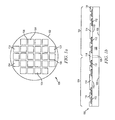
- FIGS. 1 a -1 f illustrate a method of forming semiconductor die with micro pillars
- FIG. 2 illustrates a semiconductor die with micro pillars
- FIG. 3 illustrates a semiconductor die with micro pillars formed over an insulating layer
- FIG. 4 illustrates a semiconductor die with micro pillars formed over an RDL
- FIGS. 5 a -5 f illustrate a method of forming a DCALGA package using semiconductor die with micro pillars
- FIGS. 6 a -6 b illustrate a DCALGA package including a semiconductor die with micro pillars
- FIG. 7 illustrates a DCALGA package including a heat spreader and multiple semiconductor die with micro pillars
- FIG. 8 illustrates a DCALGA package including an exposed heat spreader and multiple semiconductor die with micro pillars.
- Front-end manufacturing involves the formation of a plurality of die on the surface of a semiconductor wafer.
- Each die on the wafer contains active and passive electrical components, which are electrically connected to form functional electrical circuits.
- Active electrical components such as transistors and diodes, have the ability to control the flow of electrical current.
- Passive electrical components such as capacitors, inductors, and resistors, create a relationship between voltage and current necessary to perform electrical circuit functions.
- Passive and active components are formed over the surface of the semiconductor wafer by a series of process steps including doping, deposition, photolithography, etching, and planarization.
- Doping introduces impurities into the semiconductor material by techniques such as ion implantation or thermal diffusion.
- the doping process modifies the electrical conductivity of semiconductor material in active devices by dynamically changing the semiconductor material conductivity in response to an electric field or base current.
- Transistors contain regions of varying types and degrees of doping arranged as necessary to enable the transistor to promote or restrict the flow of electrical current upon the application of the electric field or base current.
- Active and passive components are formed by layers of materials with different electrical properties.
- the layers can be formed by a variety of deposition techniques determined in part by the type of material being deposited. For example, thin film deposition can involve chemical vapor deposition (CVD), physical vapor deposition (PVD), electrolytic plating, and electroless plating processes.
- CVD chemical vapor deposition
- PVD physical vapor deposition
- electrolytic plating electroless plating processes.
- Each layer is generally patterned to form portions of active components, passive components, or electrical connections between components.
- Back-end manufacturing refers to cutting or singulating the finished wafer into the individual semiconductor die and packaging the semiconductor die for structural support, electrical interconnect, and environmental isolation.
- the wafer is scored and broken along non-functional regions of the wafer called saw streets or scribes.
- the wafer is singulated using a laser cutting tool or saw blade.
- the individual semiconductor die are mounted to a package substrate that includes pins or contact pads for interconnection with other system components.
- Contact pads formed over the semiconductor die are then connected to contact pads within the package.
- the electrical connections can be made with conductive layers, bumps, stud bumps, conductive paste, or wirebonds.
- An encapsulant or other molding material is deposited over the package to provide physical support and electrical isolation.
- the finished package is then inserted into an electrical system and the functionality of the semiconductor device is made available to the other system components.
- FIG. 1 a shows a semiconductor wafer 100 with a base substrate material 102 , such as silicon, germanium, aluminum phosphide, aluminum arsenide, gallium arsenide, gallium nitride, indium phosphide, silicon carbide, or other bulk semiconductor material for structural support.
- a plurality of semiconductor die or components 104 is formed on wafer 100 .
- Semiconductor die 104 are separated by a non-active, inter-die wafer area or saw street 106 as described above. Saw street 106 provides cutting areas to singulate semiconductor wafer 100 into individual semiconductor die 104 .
- FIG. 1 b shows a cross-sectional view of a portion of semiconductor wafer 100 .
- Each semiconductor die 104 has a back or non-active surface 108 and an active surface 110 containing analog or digital circuits implemented as active devices, passive devices, conductive layers, and dielectric layers formed within the die and electrically interconnected according to the electrical design and function of the die.
- the circuit includes one or more transistors, diodes, and other circuit elements formed within active surface 110 to implement analog circuits or digital circuits, such as digital signal processor (DSP), ASIC, MEMS, memory, or other signal processing circuit.
- DSP digital signal processor
- Semiconductor die 104 can also contain integrated passive devices (IPDs), such as inductors, capacitors, and resistors, for radio frequency (RF) signal processing.
- IPDs integrated passive devices
- An electrically conductive layer 112 is formed over active surface 110 using PVD, CVD, electrolytic plating, electroless plating process, or other suitable metal deposition process.
- Conductive layer 112 includes one or more layers of aluminum (Al), copper (Cu), tin (Sn), nickel (Ni), gold (Au), silver (Ag), Palladium (Pd), SnAg, SnAgCu, CuNi, CuNiAu, CuNiPdAu, or other suitable electrically conductive material or combination thereof.
- Conductive layer 112 operates as contact pads electrically connected to the circuits on active surface 110 . Contact pads 112 facilitate electrical interconnect between active circuits within semiconductor die 104 and external devices, for example, a printed circuit board (PCB).
- PCB printed circuit board
- An insulating or passivation layer 114 is formed over active surface 110 and contact pads 112 using PVD, CVD, screen printing, spin coating, spray coating, sintering, or thermal oxidation.
- Passivation layer 114 contains one or more layers of silicon dioxide (SiO2), silicon nitride (Si3N4), silicon oxynitride (SiON), tantalum pentoxide (Ta2O5), aluminum oxide (Al2O3), hafnium oxide (HfO2), benzocyclobutene (BCB), polyimide (PI), polybenzoxazoles (PBO), polymer, or other material having similar insulating and structural properties. Passivation layer 114 covers and provides protection for active surface 110 .
- Passivation layer 114 is formed over and around contact pads 112 for electrical isolation. A plurality of openings is formed in passivation layer 114 over contact pads 112 by etching, laser direct ablation (LDA), or other suitable process. The openings in passivation layer 114 expose contact pads 112 for subsequent electrical interconnection.
- LDA laser direct ablation
- a patterning or photoresist layer 116 is formed over passivation layer 114 and contact pads 112 using printing, spin coating, spray coating, or other suitable method. A portion of photoresist layer 116 is removed by etching, LDA, or other suitable process to form openings 117 . Openings 117 are formed over passivation layer 114 and contact pads 112 . Openings 117 expose and extend to contact pads 112 .
- patterned openings 117 have a circular cross-sectional area configured to form conductive pillars with a cylindrical shape including a circular cross-section. In another embodiment, patterned openings 117 have a rectangular cross-sectional area configured to form conductive pillars with a cubic shape including a rectangular cross-section.
- an electrically conductive material is deposited within openings 117 and over contact pads 112 using an evaporation, sputtering, electrolytic plating, electroless plating, screen printing process to form conductive pillars or columns 118 .
- Conductive pillars 118 include one or more layers of Al, Cu, Sn, titanium (Ti), Ni, Au, Ag, tungsten (W), or other suitable electrically conductive material.
- conductive pillars 118 are formed by plating Cu in patterned openings 117 of photoresist layer 116 . Conductive pillars 118 are electrically connected to contact pads 112 .
- An electrically conductive layer or bump material 120 is deposited over conductive pillars 118 using an evaporation, electrolytic plating, electroless plating, ball drop, or screen printing process.
- Electrically conductive layer 120 includes Al, Sn, Ni, Au, Ag, Pb, Bi, Cu, solder, or combinations thereof.
- the combination of conductive pillar 118 and conductive layer 120 constitutes a composite interconnect structure or micro pillar 122 with a non-fusible portion (conductive pillar 118 ) and a fusible portion (conductive layer 120 ).
- the non-fusible portion 118 is a Cu pillar and the fusible layer 120 is SnAg.
- non-fusible pillar portion 118 is Cu
- fusible layer 120 includes a Ni and SnAg.
- micro pillars 122 can have a cylindrical shape with a circular or oval cross-section, or micro pillars 122 can have a cubic shape with a rectangular cross-section. Micro pillars 122 have a height H1 of 50 micrometers ( ⁇ m) or less and have a diameter of 50 ⁇ m or less. Micro pillars 122 represent one type of interconnect structure that can be formed over semiconductor die 104 . The interconnect structure can also use bumps, conductive paste, stud bumps, or other electrical interconnect.
- semiconductor wafer 100 is singulated into individual semiconductor die 104 by cutting through saw street 106 using a saw blade or laser cutting tool 124 .
- FIG. 2 shows semiconductor die 104 after singulation. Micro pillars 122 are formed over and electrically connected to contact pads 112 .
- FIG. 3 shows a semiconductor die 130 , similar to semiconductor die 104 in FIG. 2 .
- Semiconductor die 130 includes an insulating or passivation layer 132 formed over passivation layer 114 .
- Insulating layer 132 is formed over passivation layer 114 and contact pads 112 using PVD, CVD, screen printing, spin coating, spray coating, sintering, or thermal oxidation.
- Insulating layer 132 contains one or more layers of PI, SiO2, Si3N4, SiON, Ta2O5, Al2O3, HfO2, BCB, PBO, polymer, or other material having similar insulating and structural properties. A portion of insulating layer 132 is removed to form a plurality of openings exposing contact pads 112 .
- the openings in insulating layer 132 are smaller, i.e., narrower, than the openings in passivation layer 114 .
- a portion of insulating layer 132 is disposed in the openings in passivation layer 114 and contacts the surface of contact pads 112 .
- Micro pillars 122 are formed over insulating layer 132 and the exposed portion of contact pads 112 .
- Non-fusible conductive pillar portion 118 of micro pillar 122 is electrically connected to contact pads 112 .
- Fusible conductive layer 120 is formed over conductive pillars 118 .
- an under bump metallization (UBM) having an adhesion layer, barrier layer, and seed or wetting layer is formed between conductive pillars 118 and contact pads 112 .
- Insulating layer 132 provides electrical insulation and stress relief to micro pillars 122 over active surface 110 .
- FIG. 4 shows a semiconductor die 134 , similar to semiconductor die 130 in FIG. 3 .
- Semiconductor die 134 includes an electrically conductive layer 136 .
- Conductive layer 136 is formed over insulating layer 132 and contact pads 112 using a patterning and metal deposition process such as PVD, CVD, sputtering, electrolytic plating, and electroless plating.
- Conductive layer 136 includes one or more layers of Al, Cu, Sn, Ni, Au, Ag, Ti, TiW, W, or other suitable electrically conductive material or combination thereof.
- One portion of conductive layer 136 is electrically connected to contact pads 112 of semiconductor die 134 .
- Other portions of conductive layer 136 are electrically common or electrically isolated depending on the design and function of semiconductor die 134 .
- Conductive layer 136 operates as a redistribution layer (RDL) to redistribute electrical connection laterally across semiconductor die 134 , i.e., conductive layer 136 redistributes electrical connection from contact pads 112 to other areas over active surface 110 of semiconductor die 134 .
- RDL redistribution layer
- An insulating or passivation layer 138 is formed over insulating layer 132 and conductive layer 136 using PVD, CVD, printing, spin coating, spray coating, sintering, or thermal oxidation.
- Insulating layer 138 includes one or more layers of SiO2, Si3N4, SiON, Ta2O5, Al2O3, PI, BCB, PBO, or other material having similar insulating and structural properties.
- a portion of insulating layer 138 is removed by etching, LDA, or other suitable process to expose portions of conductive layer 136 .
- Micro pillars 122 are formed over insulating layer 138 and the exposed portions of conductive layer 136 .
- Non-fusible conductive pillar portion 118 of micro pillar 122 is electrically connected to conductive layer 136 .
- Fusible conductive layer 120 is formed over conductive pillar 118 .
- a UBM having an adhesion layer, barrier layer, and seed or wetting layer is formed between conductive pillars 118 and conductive layer 136 .
- Conductive layer 136 redistributes signals across semiconductor die 134 and allows the location and layout of micro pillars 122 to be selected to mirror the location and layout of contact pads on any substrate or leadframe.
- FIGS. 5 a -5 f illustrate a method of forming a DCALGA package using a semiconductor die with micro pillars.
- FIG. 5 a shows a cross-sectional view of a portion of a substrate or PCB 140 containing insulating material 142 and conductive layers 144 .
- substrate 140 contains one or more laminated layers of prepreg, FR-4, FR-1, CEM-1, or CEM-3 with a combination of phenolic cotton paper, epoxy, resin, woven glass, matte glass, polyester, and other reinforcement fibers or fabrics.
- Substrate 140 can also be a leadframe, multi-layer flexible laminate, copper foil, or semiconductor wafer including an active surface containing one or more transistors, diodes, and other circuit elements to implement analog circuits or digital circuits.
- the insulating material 142 contains one or more layers of SiO2, Si3N4, SiON, Ta2O5, Al2O3, HfO2, BCB, PI, PBO, polymer, or other dielectric material having similar structural and insulating properties.
- Conductive layers 144 contain Al, Cu, Sn, Ni, Au, Ag, Ti, W, or other suitable electrically conductive material formed using a patterning and metal deposition process such as sputtering, electrolytic plating, and electroless plating.
- Conductive layers 144 include lateral RDL and vertical conductive vias that provide electrical interconnect laterally across substrate 140 and vertically between opposing surfaces 146 and 148 of substrate 140 .
- Portions of conductive layers 144 are electrically common or electrically isolated according to the design and function of the semiconductor die and other devices subsequently mounted to substrate 140 . Portions of conductive layer 144 on surface 146 provide contact pads for semiconductor die and components mounted over surface 146 . Portions of conductive layer 144 on surface 148 form leads for electrical interconnect between substrate 140 and external devices, for example a PCB.
- semiconductor die 104 are disposed over substrate 140 using, for example, a pick and place operation with active surface 110 oriented toward surface 146 of substrate 140 .
- a flux material 149 is disposed over fusible layer 120 of micro pillars 122 . Flux 149 is deposited by dipping micro pillars 122 in a flux bed prior to disposing semiconductor die 104 over substrate 140 .
- a flux material 151 is formed over conductive layer 144 of substrate 140 , as shown in FIG. 5 c.
- FIG. 5 d shows semiconductor die 104 mounted to substrate 140 .
- Fusible layer 120 is brought into physical contact with contact pad 144 for reflow.
- Fusible layer 120 of micro pillars 122 is reflowed to electrically and metallurgically connect to conductive layer 144 of substrate 140 .
- Fusible layer 120 forms an electrical and metallurgical connection to contact pads 144 upon reflow with heat or application of pressure.
- Non-fusible pillar 118 is fixed to contact pad 112 of semiconductor die 104 .
- Non-fusible pillar 118 does not melt or deform during reflow.
- non-fusible pillar 118 is formed with a material having a higher melting temperature than the material of fusible layer 120 .
- Non-fusible pillar 118 provides a gap between semiconductor die 104 and substrate 140 .
- the height of non-fusible pillar 118 is selected to maintain a fixed offset, or standoff distance, between semiconductor die 104 and surface 146 of substrate 140
- an encapsulant or mold underfill (MUF) material 150 is deposited over semiconductor die 104 and substrate 140 using a vacuum molding, paste printing, compressive molding, transfer molding, liquid encapsulant molding, spin coating, or other suitable application process.
- MUF material 150 is polymer composite material, such as epoxy resin with filler, epoxy acrylate with filler, or polymer with proper filler. MUF material 150 is non-conductive and environmentally protects semiconductor die 104 from external elements and contaminants.
- MUF material 150 is disposed over back surface 108 of semiconductor die 104 and along the four side surfaces of semiconductor die 104 .
- MUF material 150 flows around micro pillars 122 and is disposed between active surface 110 of semiconductor die 104 and surface 146 of substrate.
- the filler size of MUF material 150 is selected to allow MUF material 150 to flow between active surface 110 of semiconductor die 104 and surface 146 of substrate 140 .
- MUF material 150 is thinned in a subsequent backgrinding step to expose back surface 108 or alternatively to leave a reduced thickness of MUF material 150 over back surface 108 .
- back surface 108 is exposed from MUF material 150 by controlling the deposition of MUF material 150 to prevent MUF material 150 from flowing over back surface 108 .
- FIG. 5 f a saw blade or laser cutting device 152 cuts through MUF material 150 and substrate 140 to singulate individual DCALGA packages 154 .
- FIG. 6 a shows DCALGA package 154 after singulation.
- Semiconductor die 104 are electrically connected to conductive layers 144 of substrate 140 via micro pillars 122 .
- Semiconductor die 104 is used by way of example in the present embodiment, semiconductor die 130 from FIG. 3 or semiconductor die 134 from FIG. 4 could be used to form DCALGA package 154 .
- Conductive layers 144 provide electrical interconnect laterally across and vertically through substrate 140 according to the design and function of semiconductor die 104 . Portions of conductive layer 144 on surface 148 of substrate 140 form land grid array (LGA) leads and provide interconnection between DCALGA package 154 and external devices, for example, a PCB.
- LGA land grid array
- FIG. 6 b shows details of the interconnection between a micro pillar 122 of semiconductor die 104 and conductive layer 144 of substrate 140 .
- Non-fusible pillar 118 is fixed to contact pad 112 of semiconductor die 104 .
- Fusible layer 120 is disposed between conductive pillar 118 and contact pad 144 on surface 146 of substrate 140 .
- Reflowed fusible layer 120 forms an electrical and metallurgical connection between pillar 118 and contact pad 144 .
- the reflow of fusible layer 120 is performed at a temperature and pressure selected to prevent pillar 118 from melting or deforming during reflow.
- Non-fusible pillar 118 provides a fixed offset between semiconductor die 104 and surface 146 of substrate 140 .
- Micro pillars 122 can be formed with a narrower pitch than for example solder bumps, because only fusible layer 120 is melted during reflow. Melting only fusible layer 120 , as opposed to the entire interconnect structure, i.e., conductive pillars 118 and fusible layer 120 , reduces the volume of liquidus material during reflow and prevents melted material from spreading between adjacent traces of conductive layer 144 . Melting only fusible layer 120 decreases an occurrence of electrical shorts and increases the reliability of DCALGA 154 . The decreased pitch of micro pillars 122 also allows a greater number of micro pillars 122 to be formed over semiconductor die 104 . Accordingly, semiconductor die and devices with increased input/output density requirements can be incorporated into DCALGA 154 .
- Substrate 140 does not require a solder mask, because the decreased volume of fusible material, i.e., fusible layer 120 , employed by micro pillar 122 does not run a risk spreading between adjacent traces of conductive layer 144 during reflow. Eliminating the need to form a solder mask over substrate 140 simplifies the manufacturing process used to form substrate 140 . Eliminating the solder mask formation step also decreases manufacturing time for substrate 140 , which increases throughput and decreases an overall cost of DCALGA 154 . Additionally, eliminating a solder mask layer from substrate 140 reduces the thickness of substrate 140 and an overall thickness of DCALGA 154 .
- fusible layer 120 is comprised of lead-free materials to provide a green, environmentally friendly interconnect structure. Further, the first reflow of fusible layer 120 is performed after disposing semiconductor die 104 over the substrate 140 . Eliminating a reflow operation at the wafer level, i.e., prior to singulating semiconductor wafer 100 , reduces manufacturing time.
- Eliminating a reflow operation at the wafer level also increases device reliability, as reducing the number of reflow operations performed over semi conductor die 104 minimizes the number of heating cycles semiconductor die 104 are subjected to. Minimizing the number of heating cycles reduces the risk of warpage and device failures.
- DCALGA 154 provides a thinner package having increased reliability, faster performance speeds, and a simplified manufacturing process with reduced costs.
- FIG. 7 illustrates a DCALGA package 160 including a heat spreader and multiple semiconductor die with micro pillars.
- Semiconductor die 104 from FIG. 2 , are disposed over substrate 140 using, for example, a pick and place operation with active surface 110 oriented toward surface 146 of substrate 140 .
- substrate 140 is a leadframe.
- a flux material is disposed over micro pillars 122 or over conductive layer 144 of substrate 140 prior to mounting semiconductor die 104 .
- Semiconductor die 104 are used by way of example in the present embodiment, semiconductor die 130 from FIG. 3 and/or semiconductor die 134 from FIG. 4 could also be used to form DCALGA package 160 .
- Fusible layer 120 of micro pillars 120 is disposed over contact pads of conductive layer 144 on surface 146 of substrate 140 .
- Non-fusible pillar 118 is fixed to contact pad 112 of semiconductor die 104 .
- Fusible layer 120 is reflowed and forms an electrical and metallurgical connection to contact pads 144 on surface 146 .
- Non-fusible pillars 118 do not melt or deform during reflow.
- Non-fusible pillars 118 provide a fixed offset between semiconductor die 104 and substrate 140 . The height of non-fusible pillar 118 is selected to maintain the offset, or standoff, distance between semiconductor die 104 and surface 146 of substrate 140 .
- Semiconductor die 104 are electrically connected to one another via conductive layer 144 .
- An electrically conductive layer 162 is formed over at least one of the semiconductor die 104 .
- An adhesive material, thermal interface material (TIM), or insulation layer 164 is disposed between conductive layer 162 and back surface 108 of semiconductor die 104 .
- Conductive layer 162 is electrically connected to conductive layer 144 of substrate 140 .
- conductive layer 162 acts as a heat spreader to enhance heat dissipation from semiconductor die 104 and improve thermal performance of DCALGA 160 .
- Conductive layer 162 is Cu, Al, or other material with high thermal conductivity.
- conductive layer 162 is connected to ground and acts as a shielding layer to block or absorb EMI, RFI, harmonic distortion, and other interference. Forming a shielding layer over semiconductor die 104 improves the electrical performance of DCALGA 160 .
- MUF material 166 is deposited over semiconductor die 104 , heat spreader 162 , and substrate 140 using a vacuum molding, paste printing, compressive molding, transfer molding, liquid encapsulant molding, spin coating, or other suitable application process.
- MUF material 166 is polymer composite material, such as epoxy resin with filler, epoxy acrylate with filler, or polymer with proper filler. MUF material 166 is non-conductive and environmentally protects semiconductor die and other components from external elements and contaminants.
- MUF material 166 is disposed over heat spreader 162 , over back surfaces 108 of semiconductor die 104 , and around the side surfaces of semiconductor die 104 . MUF material 166 flows around heat spreader 162 and micro pillars 122 . MUF material 166 is disposed between active surfaces 110 of semiconductor die 104 and surface 146 of substrate 140 . The filler size of MUF material 166 is selected to allow MUF material 166 to flow between adjacent semiconductor die 104 , and between semiconductor die 104 and substrate 140 .
- a saw blade or laser cutting device similar to cutting device 152 , is used to cut through MUF material 166 and substrate 140 to singulate individual DCALGA packages 160 .
- FIG. 7 shows DCALGA package 160 after singulation.
- Semiconductor die 104 are electrically connected to conductive layers 144 of substrate 140 via micro pillars 122 .
- Conductive layers 144 provide electrical interconnect laterally across and vertically through substrate 140 according to the design and function of semiconductor die 104 . Portions of conductive layer 144 on surface 148 of substrate 140 form LGA leads, and provide interconnection between DCALGA package 160 and external devices, for example, a PCB.
- Non-fusible pillars 118 of micro pillars 122 are fixed to contact pads 112 of semiconductor die 104 .
- Fusible layer 120 of micro pillars 122 is disposed between conductive pillars 118 and contact pads 144 on surface 146 of substrate 140 .
- Reflowed fusible layer 120 forms an electrical and metallurgical connection between conductive pillars 118 and contact pads 144 .
- Non-fusible pillars 118 do not melt or deform during reflow.
- Non-fusible pillars 118 provide a fixed offset between semiconductor die 104 and surface 146 of substrate 140 .
- the pitch of micro pillars 122 can be reduced because only fusible layer 120 melts during reflow.
- melting only fusible layer 120 decreases the volume of liquidus material during reflow and prevents melted material from spreading between adjacent traces of conductive layer 144 .
- melting only fusible layer 120 decreases an occurrence of electrical shorts and increases the reliability of DCALGA 160 .
- the decreased pitch of micro pillars 122 also allows a greater number of micro pillars 122 to be formed over semiconductor die 104 . Accordingly, semiconductor die and devices with increased input/output density requirements can be incorporated into DCALGA 160 .
- Substrate 140 does not require a solder resist or solder mask over conductive layer 144 and surface 146 of substrate 140 , as the small amount of fusible material 120 employed by micro pillar 122 does not run a risk spreading between adjacent traces of conductive layer 144 during reflow, i.e., melted material fusible layer 120 will not cause conductive bridges or shorts between adjacent traces of conductive layer 144 .
- Eliminating the need to form a solder mask over substrate 140 simplifies the manufacturing process for substrate 140 . Eliminating the need to form a solder mask over substrate 140 decreases manufacturing time and costs, which increase throughput. Eliminating a solder mask layer also reduces the thickness of substrate 140 and an overall thickness of DCALGA 160 .
- Mounting semiconductor die 104 with micro pillars 122 directly to conductive layer 144 of substrate 140 minimizes interconnect distance, which increases package speed. Electrically connecting multiple semiconductor die over substrate 140 increase the performance and functionality of DCALGA 160 . Mounting semiconductor die 104 with micro pillars 122 directly to conductive layer 144 of substrate 140 minimizes package parasitic elements, e.g., parasitic RLC.
- fusible layer 120 of micro pillars 122 is comprised of lead-free materials to provide a green, environmentally friendly, interconnect structure. Further, the first reflow of fusible portions 120 is performed after disposing semiconductor die 104 over the substrate 140 .
- Eliminating a reflow operation at the wafer level, i.e., prior to singulating semiconductor wafer 100 reduces manufacturing time and increases device reliability, as reducing the number of reflow operations performed over semiconductor die 104 reduces the number of heating cycles semiconductor die 104 is subjected to. Minimizing the number of heating cycles preformed over semiconductor die 104 reduce the risk of warpage and device failures.
- Heat spreader 162 further increases the thermal performance and reliability of DCALGA 160 .
- DCALGA 160 provides a thinner package with increased reliability, faster performance speeds, a simplified manufacturing process, and decreased costs.
- FIG. 8 illustrates a DCALGA package 170 having multiple semiconductor die 104 with micro pillars 122 and an exposed heat spreader 162 .
- DCALGA package 170 a portion of MUF material 166 is removed in a backgrinding operation. The backgrinding operation reduces a thickness of MUF material 166 over back surface 108 of semiconductor die 104 and exposes heat spreader 162 . After backgrinding, surface 168 of MUF material 166 is coplanar with the surface of heat spreader 162 . Alternatively, the deposition of MUF material 166 is controlled to prevent MUF material 166 from flowing over heat spreader 162 . Exposed heat spreader 162 dissipates heat generated by semiconductor die 104 .
- Heat spreader 162 can be disposed over one or all of the semiconductor die 104 in DCALGA 170 . Exposed heat spreader 162 increases the thermal performance and reliability of DCALGA 170 .
- a saw blade or laser cutting device similar to cutting device 152 , is used to cut through MUF material 166 and substrate 140 and singulate individual DCALGA packages 170 .
- FIG. 8 shows DCALGA package 170 after singulation.
- Semiconductor die 104 are electrically connected through conductive layers 144 .
- Conductive layers 144 provide electrical interconnect laterally across and vertically through substrate 140 according to the design and function of semiconductor die 104 .
- Portions of conductive layer 144 on surface 148 of substrate 140 form LGA leads and provide interconnection between DCALGA package 170 and external devices, for example, a PCB.
- Semiconductor die 104 are used by way of example in the present embodiment, semiconductor die 130 from FIG. 3 and/or semiconductor die 134 from FIG. 4 could also be used to form DCALGA package 170 .
- Non-fusible pillars 118 of micro pillars 122 are fixed to contact pads 112 of semiconductor die 104 .
- Fusible layer 120 of micro pillars 122 is disposed between conductive pillars 118 and contact pads 144 on surface 146 of substrate 140 .
- Reflowed fusible layer 120 form electrical and metallurgical connections between conductive pillars 118 and contact pads 144 .
- Non-fusible pillars 118 do not melt or deform during reflow.
- Non-fusible pillars 118 provide a fixed offset between semiconductor die 104 and surface 146 of substrate 140 . Reflowing only fusible layer 120 allows the pitch of micro pillars 122 to be reduced.
- Melting only fusible layer 120 as opposed to the entire interconnect structure, i.e., conductive pillars 118 and fusible layer 120 , reduces a volume of liquidus material during reflow and prevents melted material from spreading between adjacent traces of conductive layer 144 during reflow. Melting only fusible layer 120 decreases an occurrence of electrical shorts and increases the reliability of DCALGA 170 .
- the decreased pitch of micro pillars 122 also allows a greater number of micro pillars 122 to be formed over semiconductor die 104 . Accordingly, semiconductor die and devices with increased input/output density requirements can be incorporated into DCALGA 170 .
- Substrate 140 does not require a solder resist or solder mask over conductive layer 144 and surface 146 of substrate 140 , as the small amount of fusible material 120 employed by micro pillar 122 does not run a risk spreading between adjacent traces of conductive layer 144 during reflow, i.e., melted material of fusible layer 120 will not form conductive bridges or shorts between adjacent traces of conductive layer 144 .
- Eliminating the need to form a solder mask over substrate 140 simplifies the manufacturing process for substrate 140 . Eliminating the need to form a solder mask over substrate 140 decreases manufacturing time and costs, which increase throughput. Eliminating a solder mask layer also reduces the thickness of 140 substrate and an overall thickness of DCALGA 170 .
- Mounting semiconductor die 104 with micro pillars 122 directly to conductive layer 144 of substrate 140 minimizes interconnect distance, which increases package speed. Electrically connecting multiple semiconductor die over substrate 140 increase the functionality and overall performance of DCALGA 170 . Mounting semiconductor die 104 having micro pillars 122 directly to conductive layer 144 minimizes package parasitic elements, e.g., parasitic RLC.
- fusible layer 120 of micro pillars 122 is comprised of lead-free materials and provides a green, environmentally friendly, interconnect structure. Further, the first reflow of fusible portions 120 is performed when semiconductor die 104 are mounted to the substrate 140 .
- Eliminating a reflow operation at the wafer level, i.e., prior to singulating semiconductor wafer 100 reduces manufacturing time and increases device reliability, as reducing the number of reflow operations performed over semiconductor die 104 minimizes the number of heating cycles semiconductor die 104 is subjected to. Minimizing the number of heating cycles performed over semiconductor die 104 reduces the risk of warpage and device failures.
- Exposed heat spreader 162 dissipated heat generated by semiconductor die 104 and increases the thermal performance and reliability of DCALGA 170 .
- DCALGA 170 provides a thinner package having increased reliability, faster performance speeds, and a simplified manufacturing process with decreased costs.
Landscapes
- Engineering & Computer Science (AREA)
- Manufacturing & Machinery (AREA)
- Internal Circuitry In Semiconductor Integrated Circuit Devices (AREA)
- Chemical & Material Sciences (AREA)
- Materials Engineering (AREA)
- Wire Bonding (AREA)
- Physics & Mathematics (AREA)
- Health & Medical Sciences (AREA)
- Electromagnetism (AREA)
- Toxicology (AREA)
- Encapsulation Of And Coatings For Semiconductor Or Solid State Devices (AREA)
- Structures Or Materials For Encapsulating Or Coating Semiconductor Devices Or Solid State Devices (AREA)
Abstract
Description
Claims (25)
Priority Applications (6)
| Application Number | Priority Date | Filing Date | Title |
|---|---|---|---|
| US14/927,361 US9875988B2 (en) | 2015-10-29 | 2015-10-29 | Semiconductor device and method of forming DCALGA package using semiconductor die with micro pillars |
| TW105129584A TWI656581B (en) | 2015-10-29 | 2016-09-12 | Semiconductor device and method for forming direct wafer bonded planar grid array package using semiconductor dies having micropillars |
| EP16188869.8A EP3163613B1 (en) | 2015-10-29 | 2016-09-15 | Semiconductor device and method of forming a package of the type direct chip attach land grid array (dcalga) using a emiconductor die with micro pillars |
| CN202110994231.9A CN113690179A (en) | 2015-10-29 | 2016-10-10 | Method of forming DCALGA package using semiconductor die with micropillars and semiconductor device |
| CN201610882505.4A CN107039337A (en) | 2015-10-29 | 2016-10-10 | Method and semiconductor device for forming a DCALGA package with a semiconductor die having micropillars |
| KR1020160131276A KR101958521B1 (en) | 2015-10-29 | 2016-10-11 | Semiconductor device and method of forming DCALGA package using semiconductor die with MICRO PILLARS |
Applications Claiming Priority (1)
| Application Number | Priority Date | Filing Date | Title |
|---|---|---|---|
| US14/927,361 US9875988B2 (en) | 2015-10-29 | 2015-10-29 | Semiconductor device and method of forming DCALGA package using semiconductor die with micro pillars |
Publications (2)
| Publication Number | Publication Date |
|---|---|
| US20170125375A1 US20170125375A1 (en) | 2017-05-04 |
| US9875988B2 true US9875988B2 (en) | 2018-01-23 |
Family
ID=56939889
Family Applications (1)
| Application Number | Title | Priority Date | Filing Date |
|---|---|---|---|
| US14/927,361 Active US9875988B2 (en) | 2015-10-29 | 2015-10-29 | Semiconductor device and method of forming DCALGA package using semiconductor die with micro pillars |
Country Status (5)
| Country | Link |
|---|---|
| US (1) | US9875988B2 (en) |
| EP (1) | EP3163613B1 (en) |
| KR (1) | KR101958521B1 (en) |
| CN (2) | CN107039337A (en) |
| TW (1) | TWI656581B (en) |
Cited By (3)
| Publication number | Priority date | Publication date | Assignee | Title |
|---|---|---|---|---|
| US20170178985A1 (en) * | 2015-12-17 | 2017-06-22 | Renesas Electronics Corporation | Semiconductor device |
| US20170352613A1 (en) * | 2016-06-03 | 2017-12-07 | Amkor Technology, Inc. | Semiconductor device and manufacturing method thereof |
| US20240421053A1 (en) * | 2023-06-14 | 2024-12-19 | Wolfspeed, Inc. | Packaged device having an integrated passive device with wafer level formed connection to at least one semiconductor device and processes for implementing the same |
Families Citing this family (30)
| Publication number | Priority date | Publication date | Assignee | Title |
|---|---|---|---|---|
| WO2017108122A1 (en) | 2015-12-23 | 2017-06-29 | Intel IP Corporation | Wafer level package structure with internal conductive layer |
| US20180240738A1 (en) * | 2017-02-22 | 2018-08-23 | Cyntec Co., Ltd. | Electronic package and fabrication method thereof |
| TWI652774B (en) | 2017-03-03 | 2019-03-01 | Siliconware Precision Industries Co., Ltd. | Electronic package manufacturing method |
| US11302592B2 (en) | 2017-03-08 | 2022-04-12 | Mediatek Inc. | Semiconductor package having a stiffener ring |
| US10573579B2 (en) | 2017-03-08 | 2020-02-25 | Mediatek Inc. | Semiconductor package with improved heat dissipation |
| US10580710B2 (en) | 2017-08-31 | 2020-03-03 | Micron Technology, Inc. | Semiconductor device with a protection mechanism and associated systems, devices, and methods |
| EP3478033B1 (en) * | 2017-10-25 | 2025-02-19 | AT & S Austria Technologie & Systemtechnik Aktiengesellschaft | Embedding component with pre-connected pillar in component carrier |
| US10446521B2 (en) * | 2017-11-07 | 2019-10-15 | Taiwan Semiconductor Manufacturing Co., Ltd. | Integrated fan-out package and method of fabricating an integrated fan-out package |
| US10381329B1 (en) | 2018-01-24 | 2019-08-13 | Micron Technology, Inc. | Semiconductor device with a layered protection mechanism and associated systems, devices, and methods |
| US10475771B2 (en) | 2018-01-24 | 2019-11-12 | Micron Technology, Inc. | Semiconductor device with an electrically-coupled protection mechanism and associated systems, devices, and methods |
| US10854533B2 (en) * | 2018-03-26 | 2020-12-01 | Advanced Semiconductor Engineering, Inc. | Semiconductor package and method for manufacturing the same |
| US10580715B2 (en) * | 2018-06-14 | 2020-03-03 | Texas Instruments Incorporated | Stress buffer layer in embedded package |
| CN110660751B (en) * | 2018-06-29 | 2025-04-01 | 台湾积体电路制造股份有限公司 | Chip package and method for manufacturing the same |
| KR102477356B1 (en) * | 2018-09-11 | 2022-12-15 | 삼성전자주식회사 | Semiconductor package |
| US10734304B2 (en) * | 2018-11-16 | 2020-08-04 | Texas Instruments Incorporated | Plating for thermal management |
| US10985109B2 (en) * | 2018-12-27 | 2021-04-20 | STATS ChipPAC Pte. Ltd. | Shielded semiconductor packages with open terminals and methods of making via two-step process |
| TWI736982B (en) * | 2019-09-17 | 2021-08-21 | 李蕙如 | Active rgb led pixel device |
| US10631405B1 (en) * | 2019-09-20 | 2020-04-21 | Raytheon Company | Additive manufacturing technology (AMT) inverted pad interface |
| US20210217707A1 (en) * | 2020-01-10 | 2021-07-15 | Mediatek Inc. | Semiconductor package having re-distribution layer structure on substrate component |
| EP3852132A1 (en) | 2020-01-20 | 2021-07-21 | Infineon Technologies Austria AG | Additive manufacturing of a frontside or backside interconnect of a semiconductor die |
| CN113725182B (en) * | 2020-03-27 | 2024-02-27 | 矽磐微电子(重庆)有限公司 | Chip packaging structure |
| US11769730B2 (en) * | 2020-03-27 | 2023-09-26 | STATS ChipPAC Pte. Ltd. | Semiconductor device and method of providing high density component spacing |
| US11581281B2 (en) * | 2020-06-26 | 2023-02-14 | Taiwan Semiconductor Manufacturing Co., Ltd. | Packaged semiconductor device and method of forming thereof |
| US11424167B2 (en) * | 2020-10-09 | 2022-08-23 | Advanced Semiconductor Engineering, Inc. | Semiconductor package structure and method for manufacturing the same |
| TWI765617B (en) * | 2021-03-23 | 2022-05-21 | 友達光電股份有限公司 | Display device |
| CN115148614A (en) * | 2021-03-30 | 2022-10-04 | 嘉盛半导体(苏州)有限公司 | Chip packaging method and chip packaging structure |
| US12482719B2 (en) * | 2022-12-27 | 2025-11-25 | Nxp Usa, Inc. | Low-stress thermal interface |
| TWI858929B (en) * | 2023-09-22 | 2024-10-11 | 同欣電子工業股份有限公司 | Light emitting diode package structure and method for manufacturing the same |
| CN118039597A (en) * | 2024-01-17 | 2024-05-14 | 苏州纳芯微电子股份有限公司 | Embedded chip substrate structure and manufacturing method |
| FR3162552A1 (en) * | 2024-05-21 | 2025-11-28 | Commissariat A L'energie Atomique Et Aux Energies Alternatives | Electronic chip assembly comprising adhesive pads directly connected to conductive tracks |
Citations (31)
| Publication number | Priority date | Publication date | Assignee | Title |
|---|---|---|---|---|
| US5147084A (en) * | 1990-07-18 | 1992-09-15 | International Business Machines Corporation | Interconnection structure and test method |
| US5261593A (en) * | 1992-08-19 | 1993-11-16 | Sheldahl, Inc. | Direct application of unpackaged integrated circuit to flexible printed circuit |
| US5448114A (en) * | 1992-07-15 | 1995-09-05 | Kabushiki Kaisha Toshiba | Semiconductor flipchip packaging having a perimeter wall |
| US5969426A (en) * | 1994-12-14 | 1999-10-19 | Mitsubishi Denki Kabushiki Kaisha | Substrateless resin encapsulated semiconductor device |
| US5977626A (en) | 1998-08-12 | 1999-11-02 | Industrial Technology Research Institute | Thermally and electrically enhanced PBGA package |
| US6050832A (en) * | 1998-08-07 | 2000-04-18 | Fujitsu Limited | Chip and board stress relief interposer |
| US6163956A (en) * | 1998-02-23 | 2000-12-26 | Micron Technology, Inc. | Method of making chip scale package with heat spreade |
| US6198169B1 (en) * | 1998-12-17 | 2001-03-06 | Shinko Electric Industries Co., Ltd. | Semiconductor device and process for producing same |
| US20010013423A1 (en) | 1996-10-31 | 2001-08-16 | Hormazdyar M. Dalal | Flip chip attach on flexible circuit carrier using chip with metallic cap on solder |
| US6365500B1 (en) * | 1994-05-06 | 2002-04-02 | Industrial Technology Research Institute | Composite bump bonding |
| US20030049411A1 (en) | 2001-09-10 | 2003-03-13 | Delphi Technologies,Inc | No-flow underfill material and underfill method for flip chip devices |
| US6563712B2 (en) * | 1999-07-30 | 2003-05-13 | Micron Technology, Inc. | Heak sink chip package |
| US20030183947A1 (en) * | 2002-04-01 | 2003-10-02 | Nec Electronics Corporation | Flip-chip type semiconductor device, process for manufacturing such semiconductor device, and process for mounting such semiconductor device |
| US6653730B2 (en) * | 2000-12-14 | 2003-11-25 | Intel Corporation | Electronic assembly with high capacity thermal interface |
| US20040035909A1 (en) | 2002-08-22 | 2004-02-26 | Shing Yeh | Lead-based solder alloys containing copper |
| US20050087852A1 (en) * | 2003-04-22 | 2005-04-28 | Kai-Chi Chen | Chip package structure and process for fabricating the same |
| US6943058B2 (en) | 2003-03-18 | 2005-09-13 | Delphi Technologies, Inc. | No-flow underfill process and material therefor |
| US20080265412A1 (en) * | 2007-04-27 | 2008-10-30 | Oki Electric Industry Co., Ltd. | Semiconductor device and method of manufacturing thereof |
| US20090039514A1 (en) * | 2007-08-08 | 2009-02-12 | Casio Computer Co., Ltd. | Semiconductor device and method for manufacturing the same |
| US20100159645A1 (en) * | 1998-09-01 | 2010-06-24 | Sony Corporation | Semiconductor apparatus and process of production thereof |
| US20100187659A1 (en) * | 2004-11-16 | 2010-07-29 | Rohm Co., Ltd. | Semiconductor device and method for manufacturing semiconductor device |
| US20100246152A1 (en) | 2009-03-30 | 2010-09-30 | Megica Corporation | Integrated circuit chip using top post-passivation technology and bottom structure technology |
| US7906857B1 (en) | 2008-03-13 | 2011-03-15 | Xilinx, Inc. | Molded integrated circuit package and method of forming a molded integrated circuit package |
| US20110084386A1 (en) | 2003-11-10 | 2011-04-14 | Stats Chippac, Ltd. | Semiconductor Device and Method of Self-Confinement of Conductive Bump Material During Reflow Without Solder Mask |
| US20110117700A1 (en) * | 2009-11-18 | 2011-05-19 | Advanced Semiconductor Engineering, Inc. | Stackable semiconductor device packages |
| US20120273935A1 (en) * | 2011-04-29 | 2012-11-01 | Stefan Martens | Semiconductor Device and Method of Making a Semiconductor Device |
| US20120286408A1 (en) | 2011-05-10 | 2012-11-15 | Conexant Systems, Inc. | Wafer level package with thermal pad for higher power dissipation |
| US20130087366A1 (en) | 2011-10-07 | 2013-04-11 | Volterra Semiconductor Corporation | Power management applications of interconnect substrates |
| US20130334685A1 (en) * | 2012-06-14 | 2013-12-19 | SK Hynix Inc. | Embedded packages and methods of manufacturing the same |
| US20140038353A1 (en) * | 2012-08-03 | 2014-02-06 | Samsung Electronics Co., Ltd. | Semiconductor packages, methods of manufacturing the same, and semiconductor package structures including the same |
| US20140131856A1 (en) | 2012-11-09 | 2014-05-15 | Won Chul Do | Semiconductor device and manufacturing method thereof |
Family Cites Families (2)
| Publication number | Priority date | Publication date | Assignee | Title |
|---|---|---|---|---|
| US9312230B2 (en) * | 2010-02-08 | 2016-04-12 | Taiwan Semiconductor Manufacturing Company, Ltd. | Conductive pillar structure for semiconductor substrate and method of manufacture |
| KR101195271B1 (en) * | 2011-04-29 | 2012-11-14 | 에스케이하이닉스 주식회사 | Semiconductor apparatus and method for fabricating the same |
-
2015
- 2015-10-29 US US14/927,361 patent/US9875988B2/en active Active
-
2016
- 2016-09-12 TW TW105129584A patent/TWI656581B/en active
- 2016-09-15 EP EP16188869.8A patent/EP3163613B1/en active Active
- 2016-10-10 CN CN201610882505.4A patent/CN107039337A/en active Pending
- 2016-10-10 CN CN202110994231.9A patent/CN113690179A/en active Pending
- 2016-10-11 KR KR1020160131276A patent/KR101958521B1/en active Active
Patent Citations (32)
| Publication number | Priority date | Publication date | Assignee | Title |
|---|---|---|---|---|
| US5147084A (en) * | 1990-07-18 | 1992-09-15 | International Business Machines Corporation | Interconnection structure and test method |
| US5448114A (en) * | 1992-07-15 | 1995-09-05 | Kabushiki Kaisha Toshiba | Semiconductor flipchip packaging having a perimeter wall |
| US5261593A (en) * | 1992-08-19 | 1993-11-16 | Sheldahl, Inc. | Direct application of unpackaged integrated circuit to flexible printed circuit |
| US6365500B1 (en) * | 1994-05-06 | 2002-04-02 | Industrial Technology Research Institute | Composite bump bonding |
| US5969426A (en) * | 1994-12-14 | 1999-10-19 | Mitsubishi Denki Kabushiki Kaisha | Substrateless resin encapsulated semiconductor device |
| US20010013423A1 (en) | 1996-10-31 | 2001-08-16 | Hormazdyar M. Dalal | Flip chip attach on flexible circuit carrier using chip with metallic cap on solder |
| US6163956A (en) * | 1998-02-23 | 2000-12-26 | Micron Technology, Inc. | Method of making chip scale package with heat spreade |
| US6050832A (en) * | 1998-08-07 | 2000-04-18 | Fujitsu Limited | Chip and board stress relief interposer |
| US5977626A (en) | 1998-08-12 | 1999-11-02 | Industrial Technology Research Institute | Thermally and electrically enhanced PBGA package |
| US20100159645A1 (en) * | 1998-09-01 | 2010-06-24 | Sony Corporation | Semiconductor apparatus and process of production thereof |
| US6198169B1 (en) * | 1998-12-17 | 2001-03-06 | Shinko Electric Industries Co., Ltd. | Semiconductor device and process for producing same |
| US6563712B2 (en) * | 1999-07-30 | 2003-05-13 | Micron Technology, Inc. | Heak sink chip package |
| US6653730B2 (en) * | 2000-12-14 | 2003-11-25 | Intel Corporation | Electronic assembly with high capacity thermal interface |
| US20030049411A1 (en) | 2001-09-10 | 2003-03-13 | Delphi Technologies,Inc | No-flow underfill material and underfill method for flip chip devices |
| US6660560B2 (en) | 2001-09-10 | 2003-12-09 | Delphi Technologies, Inc. | No-flow underfill material and underfill method for flip chip devices |
| US20030183947A1 (en) * | 2002-04-01 | 2003-10-02 | Nec Electronics Corporation | Flip-chip type semiconductor device, process for manufacturing such semiconductor device, and process for mounting such semiconductor device |
| US20040035909A1 (en) | 2002-08-22 | 2004-02-26 | Shing Yeh | Lead-based solder alloys containing copper |
| US6943058B2 (en) | 2003-03-18 | 2005-09-13 | Delphi Technologies, Inc. | No-flow underfill process and material therefor |
| US20050087852A1 (en) * | 2003-04-22 | 2005-04-28 | Kai-Chi Chen | Chip package structure and process for fabricating the same |
| US20110084386A1 (en) | 2003-11-10 | 2011-04-14 | Stats Chippac, Ltd. | Semiconductor Device and Method of Self-Confinement of Conductive Bump Material During Reflow Without Solder Mask |
| US20100187659A1 (en) * | 2004-11-16 | 2010-07-29 | Rohm Co., Ltd. | Semiconductor device and method for manufacturing semiconductor device |
| US20080265412A1 (en) * | 2007-04-27 | 2008-10-30 | Oki Electric Industry Co., Ltd. | Semiconductor device and method of manufacturing thereof |
| US20090039514A1 (en) * | 2007-08-08 | 2009-02-12 | Casio Computer Co., Ltd. | Semiconductor device and method for manufacturing the same |
| US7906857B1 (en) | 2008-03-13 | 2011-03-15 | Xilinx, Inc. | Molded integrated circuit package and method of forming a molded integrated circuit package |
| US20100246152A1 (en) | 2009-03-30 | 2010-09-30 | Megica Corporation | Integrated circuit chip using top post-passivation technology and bottom structure technology |
| US20110117700A1 (en) * | 2009-11-18 | 2011-05-19 | Advanced Semiconductor Engineering, Inc. | Stackable semiconductor device packages |
| US20120273935A1 (en) * | 2011-04-29 | 2012-11-01 | Stefan Martens | Semiconductor Device and Method of Making a Semiconductor Device |
| US20120286408A1 (en) | 2011-05-10 | 2012-11-15 | Conexant Systems, Inc. | Wafer level package with thermal pad for higher power dissipation |
| US20130087366A1 (en) | 2011-10-07 | 2013-04-11 | Volterra Semiconductor Corporation | Power management applications of interconnect substrates |
| US20130334685A1 (en) * | 2012-06-14 | 2013-12-19 | SK Hynix Inc. | Embedded packages and methods of manufacturing the same |
| US20140038353A1 (en) * | 2012-08-03 | 2014-02-06 | Samsung Electronics Co., Ltd. | Semiconductor packages, methods of manufacturing the same, and semiconductor package structures including the same |
| US20140131856A1 (en) | 2012-11-09 | 2014-05-15 | Won Chul Do | Semiconductor device and manufacturing method thereof |
Cited By (6)
| Publication number | Priority date | Publication date | Assignee | Title |
|---|---|---|---|---|
| US20170178985A1 (en) * | 2015-12-17 | 2017-06-22 | Renesas Electronics Corporation | Semiconductor device |
| US20170352613A1 (en) * | 2016-06-03 | 2017-12-07 | Amkor Technology, Inc. | Semiconductor device and manufacturing method thereof |
| US10504827B2 (en) * | 2016-06-03 | 2019-12-10 | Amkor Technology, Inc. | Semiconductor device and manufacturing method thereof |
| US11444013B2 (en) | 2016-06-03 | 2022-09-13 | Amkor Technology Singapore Holding Pte. Ltd. | Semiconductor device and manufacturing method thereof |
| US12581970B2 (en) | 2016-06-03 | 2026-03-17 | Amkor Technology Singapore Holding Pte. Ltd. | Semiconductor device and manufacturing method thereof |
| US20240421053A1 (en) * | 2023-06-14 | 2024-12-19 | Wolfspeed, Inc. | Packaged device having an integrated passive device with wafer level formed connection to at least one semiconductor device and processes for implementing the same |
Also Published As
| Publication number | Publication date |
|---|---|
| TW201727772A (en) | 2017-08-01 |
| US20170125375A1 (en) | 2017-05-04 |
| TWI656581B (en) | 2019-04-11 |
| CN113690179A (en) | 2021-11-23 |
| CN107039337A (en) | 2017-08-11 |
| KR101958521B1 (en) | 2019-03-14 |
| EP3163613A1 (en) | 2017-05-03 |
| KR20170051252A (en) | 2017-05-11 |
| EP3163613B1 (en) | 2024-08-21 |
Similar Documents
| Publication | Publication Date | Title |
|---|---|---|
| US9875988B2 (en) | Semiconductor device and method of forming DCALGA package using semiconductor die with micro pillars | |
| US9601461B2 (en) | Semiconductor device and method of forming inverted pyramid cavity semiconductor package | |
| US8409979B2 (en) | Semiconductor device and method of forming interconnect structure with conductive pads having expanded interconnect surface area for enhanced interconnection properties | |
| US11715703B2 (en) | EMI shielding for flip chip package with exposed die backside | |
| US8587120B2 (en) | Semiconductor device and method of forming interconnect structure over seed layer on contact pad of semiconductor die without undercutting seed layer beneath interconnect structure | |
| KR101647853B1 (en) | Semiconductor device and method of forming adjacent channel and dam material around die attach area of substrate to control outward flow of underfill material | |
| US8492197B2 (en) | Semiconductor device and method of forming vertically offset conductive pillars over first substrate aligned to vertically offset BOT interconnect sites formed over second substrate | |
| TWI614859B (en) | Semiconductor device and method of forming a semiconductor device having a fan-out interconnect structure to reduce substrate complexity | |
| US10096540B2 (en) | Semiconductor device and method of forming dummy pillars between semiconductor die and substrate for maintaining standoff distance | |
| US7842607B2 (en) | Semiconductor device and method of providing a thermal dissipation path through RDL and conductive via | |
| US9252094B2 (en) | Semiconductor device and method of forming an interconnect structure with conductive material recessed within conductive ring over surface of conductive pillar | |
| US8288202B2 (en) | Method of forming partially-etched conductive layer recessed within substrate for bonding to semiconductor die | |
| US20120061824A1 (en) | Semiconductor device and method of forming bond-on-lead interconnection for mounting semiconductor die in fo-wlcsp | |
| US9230896B2 (en) | Semiconductor device and method of reflow soldering for conductive column structure in flip chip package | |
| US8895430B2 (en) | Method of making a semiconductor device comprising a land grid array flip chip bump system with short bumps |
Legal Events
| Date | Code | Title | Description |
|---|---|---|---|
| AS | Assignment |
Owner name: SEMTECH CORPORATION, CALIFORNIA Free format text: ASSIGNMENT OF ASSIGNORS INTEREST;ASSIGNORS:CHINNUSAMY, SATYAMOORTHI;TAN, WENG HING;HO, KOK KHOON;AND OTHERS;REEL/FRAME:036918/0416 Effective date: 20151028 |
|
| AS | Assignment |
Owner name: HSBC BANK USA, NATIONAL ASSOCIATION, CALIFORNIA Free format text: SECURITY INTEREST;ASSIGNOR:SEMTECH CORPORATION;REEL/FRAME:038684/0563 Effective date: 20160131 |
|
| AS | Assignment |
Owner name: HSBC BANK USA, NATIONAL ASSOCIATION, AS ADMINISTRA Free format text: SECURITY INTEREST;ASSIGNORS:SEMTECH CORPORATION;SEMTECH NEW YORK CORPORATION;SIERRA MONOLITHICS, INC.;AND OTHERS;SIGNING DATES FROM 20151115 TO 20161115;REEL/FRAME:040646/0799 Owner name: HSBC BANK USA, NATIONAL ASSOCIATION, AS ADMINISTRATIVE AGENT, CALIFORNIA Free format text: SECURITY INTEREST;ASSIGNORS:SEMTECH CORPORATION;SEMTECH NEW YORK CORPORATION;SIERRA MONOLITHICS, INC.;AND OTHERS;SIGNING DATES FROM 20151115 TO 20161115;REEL/FRAME:040646/0799 |
|
| STCF | Information on status: patent grant |
Free format text: PATENTED CASE |
|
| MAFP | Maintenance fee payment |
Free format text: PAYMENT OF MAINTENANCE FEE, 4TH YEAR, LARGE ENTITY (ORIGINAL EVENT CODE: M1551); ENTITY STATUS OF PATENT OWNER: LARGE ENTITY Year of fee payment: 4 |
|
| AS | Assignment |
Owner name: JPMORGAN CHASE BANK, N.A., AS SUCCESSOR AGENT, ILLINOIS Free format text: ASSIGNMENT OF PATENT SECURITY INTEREST PREVIOUSLY RECORDED AT REEL/FRAME (038684/0563);ASSIGNOR:HSBC BANK USA, NATIONAL ASSOCIATION, AS RESIGNING AGENT;REEL/FRAME:062780/0465 Effective date: 20230210 Owner name: JPMORGAN CHASE BANK, N.A., AS SUCCESSOR AGENT, ILLINOIS Free format text: ASSIGNMENT OF PATENT SECURITY INTEREST PREVIOUSLY RECORDED AT REEL/FRAME (040646/0799);ASSIGNOR:HSBC BANK USA, NATIONAL ASSOCIATION, AS RESIGNING AGENT;REEL/FRAME:062781/0544 Effective date: 20230210 |
|
| MAFP | Maintenance fee payment |
Free format text: PAYMENT OF MAINTENANCE FEE, 8TH YEAR, LARGE ENTITY (ORIGINAL EVENT CODE: M1552); ENTITY STATUS OF PATENT OWNER: LARGE ENTITY Year of fee payment: 8 |