US980805A - Electric-lamp-holding socket. - Google Patents
Electric-lamp-holding socket. Download PDFInfo
- Publication number
- US980805A US980805A US44514908A US1908445149A US980805A US 980805 A US980805 A US 980805A US 44514908 A US44514908 A US 44514908A US 1908445149 A US1908445149 A US 1908445149A US 980805 A US980805 A US 980805A
- Authority
- US
- United States
- Prior art keywords
- lamp
- base
- socket
- receiver
- screw
- Prior art date
- Legal status (The legal status is an assumption and is not a legal conclusion. Google has not performed a legal analysis and makes no representation as to the accuracy of the status listed.)
- Expired - Lifetime
Links
- XEEYBQQBJWHFJM-UHFFFAOYSA-N Iron Chemical compound [Fe] XEEYBQQBJWHFJM-UHFFFAOYSA-N 0.000 description 10
- 229910052742 iron Inorganic materials 0.000 description 5
- 239000002184 metal Substances 0.000 description 3
- 229910052751 metal Inorganic materials 0.000 description 3
- 230000002093 peripheral effect Effects 0.000 description 3
- 229910001369 Brass Inorganic materials 0.000 description 2
- 239000010951 brass Substances 0.000 description 2
- 239000000463 material Substances 0.000 description 2
- 241000183024 Populus tremula Species 0.000 description 1
- 239000004568 cement Substances 0.000 description 1
- 108010085990 projectin Proteins 0.000 description 1
Images
Classifications
-
- H—ELECTRICITY
- H01—ELECTRIC ELEMENTS
- H01R—ELECTRICALLY-CONDUCTIVE CONNECTIONS; STRUCTURAL ASSOCIATIONS OF A PLURALITY OF MUTUALLY-INSULATED ELECTRICAL CONNECTING ELEMENTS; COUPLING DEVICES; CURRENT COLLECTORS
- H01R33/00—Coupling devices specially adapted for supporting apparatus and having one part acting as a holder providing support and electrical connection via a counterpart which is structurally associated with the apparatus, e.g. lamp holders; Separate parts thereof
- H01R33/05—Two-pole devices
- H01R33/22—Two-pole devices for screw type base, e.g. for lamp
-
- H—ELECTRICITY
- H01—ELECTRIC ELEMENTS
- H01R—ELECTRICALLY-CONDUCTIVE CONNECTIONS; STRUCTURAL ASSOCIATIONS OF A PLURALITY OF MUTUALLY-INSULATED ELECTRICAL CONNECTING ELEMENTS; COUPLING DEVICES; CURRENT COLLECTORS
- H01R2103/00—Two poles
Definitions
- ⁇ n r i will be utilized for e ectrical contact with the receiver of the socket.
- My invention re ates to improvements in electric lamp holding sockets, and the objectsof my invention are: First, to provide a socket in which the entire screw surface of the screw plug of the lamp s brought into direct electrical contact with the entire screw surface of the receiver of the socket, thus insuring that the entire screw surface of the outer current flowin pole of the lamps plug socket that is arranged to prevent accidental short clrcuitmg of the sockets or receptacles. And third, to provide a socket especially also for electric signs, that is simple, thoroughly practical, and will fully meet the requirements of the National Board of Und erwriters. I attain these objects by the mechanism illustrated in the accompanying drawings, in which:
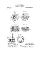
- Figure 1 is a plan view of the improved electric lamp socket, the clamping cap being shown in operative position.
- Fig. 2 is a i similar view with the cap removed:
- Fig. 3 is a vertical, sectional view thereof, on the line 3-3 of Fig. I.
- Fig. 4 is a vertical, sectional view on the line 4-4 of Fig. l, the cap and metal lamp holder bein; omitted.
- Fig. 5 is a bottom view of the socket. Inc termi nals being omitted.
- Fig. 6, is an elevation of the device showing the same clmnped to the lid of the ordinary socket holding casing.
- the numeral 1. designates the base portion of my improved electric lamp supporting socket.
- 'lhisv base portion may be of any desired form. but 1' preferably make it circular.
- 'lhis base is provided with a large axialrhzunlwr "2. which extends nearly but not quite through forms the lu-riphcral portion of the base.
- the central portion of the lower end por tion of this base is nnporl'orate and is pro which acts as an insulating medium between cuit wire.
- connecting strips 4 and 5 and prevents accidental short circuiting of these termina ls across the bottom of the base.
- These terminal contact strips comprise stri s (If any suitable conductive metal, brass.
- the terminal contact strip' l acts as the ter-f through it and the aperture in the base and screws into a threaded hole formed 1n the stri p l to receive it, and to the axial center of the chamber of the base, and on its end portion that. terminates in thecenter of the clnnnber, a slightly raised cone portion 11 is formed, which is adapted to contact-with the terminal pole in the center of the end of toe the screw plug of the lamp.
- the terminal contact strip 4 is c.( )nsequcntly the circuit.” wire connecting terminal of 'the conlact'terminal pole strip 10, of the center pole of the lamp.
- binding screw 12 is threaded tot-ho strip l adjacent to its outer endportion, and the outer end of the strip is turned slightly upward to shield the end of the circuit wirev and to engage the end of the wire and to firmly secure it by the screw between the screw and the strip.
- the terminal contact strip 5 formsthe terminal pole of a lamp receiving shell 13, which is provided at. its lower endwith out-- wardly projecting feet l-t, which are secured to the lloor portion of the chamber by screws lb and "the. screw 9.
- the screws 15 extend through apertures formed through the floor of the chamber of the base, and screwinto nuts, which are set into apertures 17 formed in the lower end 6 of the base at the side of the projecting insulating lug portion, and the aperture '17 over the nuts is filled with non-conductive cement.
- the screw 9 extends loosely through the one foot of the receiver which is arranged-over the terminal contact strip 5, and through an aperture in the bottom of the base, and'screws into the inner end'of the cont-act terminal strip 5, thus clamping the foot of the receiver and the strip 5, together to the base, and providing a circuit through the screw from the receiver to the contact terminal strip
- This strip 5 is also provided with a binding screw 12, and a turned up outer end portion similar to and for the same purpose as the contact terminal strip 4.
- the receiver 13 comprises an inter nal and an external threaded shell of any suitable conductive metal, preferably brass,
- a gap 19 is'cut in the lower end of the receiver opposite to the foot that is con- -nected to the terminal contact strip; 4, and
- the receiver 1 use in my present invention is made enough shorter than the one illustrated in my former applications to permit the lower non-threaded portion of the screw plug end of the lamp to screw through and beyond the lower end of it into a concentric recess 20, which is formed in the floor portion of the chamber in the base.
- this cap is provided with an annularly projectin flange which fits loosely into and exten s into the annular space between the walls of the chamber and the receiver.
- the aperture through the cap and its projecting annular portion is interiorly threaded and formed toscrew onto the outside thread of the receiver.
- The'an-' nnlar projecting flange thus projects into the annular recess and incases the receiver with a non-conductive insulative material, while the top of the cap is made enough larger than the annular flange to extend over the annular peripheral shell of the base portion, and is made especially so in order that the base and cap can be placed onopposite sides of sign boards, and to the covers 22 of the standard, iron socket 'inclosing boxes 23. These boxes are commonly used at the present time in wiring buildings.
- My improved iron box and sign socket is particularly adapted for'use' in horizontal and vertical positions in the iron boxes, and the box is provided with apertures 26 and '27 that permit the current line wires to be attached to the base in either a horizontal or a vertical position. 7
- a lamp socket comprising a body of in sulating material, having its walls shaped to form therein concentric chambers, onc of smaller'diameter than the other, the walls of said smaller chamber having a slot thereslot and means extending through the body portion of the socket to the bottom thereof for making electrical connection to said strip, a conducting screw-threaded shell, having enough threads to engage all the threads on a lamp, supported on the bottom of said larger forms the clamping member ofthe socket.
Landscapes
- Common Detailed Techniques For Electron Tubes Or Discharge Tubes (AREA)
Description
H. W. LAWRENCE. ELEGTBIG LAMP HOLDING SOCKET.
APIPLIOATIOH FILED JULY 24, 1908.
Patented Jan. 3, 1911.
\n r i will be utilized for e ectrical contact with the receiver of the socket. Second, to provide a "it. and leaves a ihin shell portion that adapted for the commonly used iron box and vidcd .with;. a projecting his portion UNITED S T HEENT OFFICE HARRY W. LAWRENCE, OF DENVER, COLORADO.
ELECTRIC-LAMP-HOLDING- SOCKET.
Specification of Letters Patent.
Application filed July 24, 1908. Serial No. 445,149.
To all whom it may concern:
Be it known that I, HARRY \V. LAWRENCE, a citizen of the United States of America, residing in the city and county of Denver and State of Colorado, have invented a new and useful Electric-Lamp-Holding Socket, of which the followin is a specification.
My invention re ates to improvements in electric lamp holding sockets, and the objectsof my invention are: First, to provide a socket in which the entire screw surface of the screw plug of the lamp s brought into direct electrical contact with the entire screw surface of the receiver of the socket, thus insuring that the entire screw surface of the outer current flowin pole of the lamps plug socket that is arranged to prevent accidental short clrcuitmg of the sockets or receptacles. And third, to provide a socket especially also for electric signs, that is simple, thoroughly practical, and will fully meet the requirements of the National Board of Und erwriters. I attain these objects by the mechanism illustrated in the accompanying drawings, in which:
Figure 1, is a plan view of the improved electric lamp socket, the clamping cap being shown in operative position. Fig. 2, is a i similar view with the cap removed: Fig. 3, is a vertical, sectional view thereof, on the line 3-3 of Fig. I. Fig. 4, is a vertical, sectional view on the line 4-4 of Fig. l, the cap and metal lamp holder bein; omitted. Fig. 5, is a bottom view of the socket. Inc termi nals being omitted. And Fig. 6, is an elevation of the device showing the same clmnped to the lid of the ordinary socket holding casing.
Similar letters of reference refer to similar parts throughout the several views.
Referring to the drawings, the numeral 1. designates the base portion of my improved electric lamp supporting socket. 'lhisv base portion may be of any desired form. but 1' preferably make it circular. 'lhis base is provided with a large axialrhzunlwr "2. which extends nearly but not quite through forms the lu-riphcral portion of the base. The central portion of the lower end por tion of this base is nnporl'orate and is pro which acts as an insulating medium between cuit wire. connecting strips 4 and 5, and prevents accidental short circuiting of these termina ls across the bottom of the base. These terminal contact strips comprise stri s (If any suitable conductive metal, brass. eing preferably used, and they are positioned diametrically opposite each other on the opposite sides of the projecting lug portion 3, and are seated on the rim portion of the lower end (3 of the base, a slight radial lug portion 7 being formed on the peripheral surface of the base to form a seat surface, for them. These terminal contact strips arose-- cured at their inner end portions to the lower rim'portion of the base by screws8 and 9,
which ektend through apertures formed through the rim portion of the bottom of the base from the inside of the chamber 2, and,
the terminal contact strip' l acts as the ter-f through it and the aperture in the base and screws into a threaded hole formed 1n the stri p l to receive it, and to the axial center of the chamber of the base, and on its end portion that. terminates in thecenter of the clnnnber, a slightly raised cone portion 11 is formed, which is adapted to contact-with the terminal pole in the center of the end of toe the screw plug of the lamp. The terminal contact strip 4 is c.( )nsequcntly the circuit." wire connecting terminal of 'the conlact'terminal pole strip 10, of the center pole of the lamp. binding screw 12 is threaded tot-ho strip l adjacent to its outer endportion, and the outer end of the strip is turned slightly upward to shield the end of the circuit wirev and to engage the end of the wire and to firmly secure it by the screw between the screw and the strip.
The terminal contact strip 5 formsthe terminal pole of a lamp receiving shell 13, which is provided at. its lower endwith out-- wardly projecting feet l-t, which are secured to the lloor portion of the chamber by screws lb and "the. screw 9. The screws 15 extend through apertures formed through the floor of the chamber of the base, and screwinto nuts, which are set into apertures 17 formed in the lower end 6 of the base at the side of the projecting insulating lug portion, and the aperture '17 over the nuts is filled with non-conductive cement. The screw 9, extends loosely through the one foot of the receiver which is arranged-over the terminal contact strip 5, and through an aperture in the bottom of the base, and'screws into the inner end'of the cont-act terminal strip 5, thus clamping the foot of the receiver and the strip 5, together to the base, and providing a circuit through the screw from the receiver to the contact terminal strip This strip 5 is also provided with a binding screw 12, and a turned up outer end portion similar to and for the same purpose as the contact terminal strip 4. The receiver 13 comprises an inter nal and an external threaded shell of any suitable conductive metal, preferably brass,
and forms an important element of Patent N 0. 864,427 issued to me August 27, 1907.
A gap 19 is'cut in the lower end of the receiver opposite to the foot that is con- -nected to the terminal contact strip; 4, and
the receiver 1 use in my present invention is made enough shorter than the one illustrated in my former applications to permit the lower non-threaded portion of the screw plug end of the lamp to screw through and beyond the lower end of it into a concentric recess 20, which is formed in the floor portion of the chamber in the base. In order to accomplish this desirable object, and remedy a serious fault that exists in all of the presently used sockets and receivers, I have had to shorten the lower end portion of the receiver below the ends of its lower threads over the length of the receivers illustrated in my former applications, and I have also found it necessary to form the concentr1c recess 20 in the center of the floor portion of the chamber of the base in order to allow the end of the lamps plug to extend through and beyond the lower end of the receiver far enough to permit its upper end thread to screw down into the receiver to its upper end, and T have arranged the receiver so that when the lamp )lug is screwedinto it to the end of its threat the lower end of the receivers interior threads will register with the lower end of the plugs threads. Consequently the threaded surface of the receiver and of the plug are of the same length and all of the out flowing current surface The under side of this cap is provided with an annularly projectin flange which fits loosely into and exten s into the annular space between the walls of the chamber and the receiver. The aperture through the cap and its projecting annular portion is interiorly threaded and formed toscrew onto the outside thread of the receiver. The'an-' nnlar projecting flange thus projects into the annular recess and incases the receiver with a non-conductive insulative material, while the top of the cap is made enough larger than the annular flange to extend over the annular peripheral shell of the base portion, and is made especially so in order that the base and cap can be placed onopposite sides of sign boards, and to the covers 22 of the standard, iron socket 'inclosing boxes 23. These boxes are commonly used at the present time in wiring buildings.
use in connection with these iron boxes, and for signs,-the flange of the cap being espe cially designed to extend through an a erture 24 formed through the cover of the ox r through a sign board, and the under side of the head of the cap, to bear flush against My socket has been especially designed for the surface of the cover or sign board. The
the operator, whilethe peripheral surface of the shell of the base is sufliciently uneven owing to the cut away portions and the projecting lugs of the contact terminal strips the base.
My improved iron box and sign socket is particularly adapted for'use' in horizontal and vertical positions in the iron boxes, and the box is provided with apertures 26 and '27 that permit the current line wires to be attached to the base in either a horizontal or a vertical position. 7
' Iaving described my invention, what I claim as new and desire to secure by Letters Patent, is
A lamp socket comprising a body of in sulating material, having its walls shaped to form therein concentric chambers, onc of smaller'diameter than the other, the walls of said smaller chamber having a slot thereslot and means extending through the body portion of the socket to the bottom thereof for making electrical connection to said strip, a conducting screw-threaded shell, having enough threads to engage all the threads on a lamp, supported on the bottom of said larger forms the clamping member ofthe socket.
recess, and means extending' through the in, a contact strip extending through saida friction gripping surface for the hands of to afford a good hand gripping surface on body portion of the socket to the bottom I thereof to make electrical connections with said shell and to secure it in. place, and a ring-shaped cap having an outwardly ex- 5 tending flange and internal screW-threeds' for eiwaging the external screw-threads on the shil.
In testimony whereof I affix my signature m presence of tWo Witnesses.
HARRY W. LAWRENCE.
Witnesses:
G. SARGENT ELLIOIT, ADELLA M. FOWIF.
Priority Applications (1)
| Application Number | Priority Date | Filing Date | Title |
|---|---|---|---|
| US44514908A US980805A (en) | 1908-07-24 | 1908-07-24 | Electric-lamp-holding socket. |
Applications Claiming Priority (1)
| Application Number | Priority Date | Filing Date | Title |
|---|---|---|---|
| US44514908A US980805A (en) | 1908-07-24 | 1908-07-24 | Electric-lamp-holding socket. |
Publications (1)
| Publication Number | Publication Date |
|---|---|
| US980805A true US980805A (en) | 1911-01-03 |
Family
ID=3049172
Family Applications (1)
| Application Number | Title | Priority Date | Filing Date |
|---|---|---|---|
| US44514908A Expired - Lifetime US980805A (en) | 1908-07-24 | 1908-07-24 | Electric-lamp-holding socket. |
Country Status (1)
| Country | Link |
|---|---|
| US (1) | US980805A (en) |
-
1908
- 1908-07-24 US US44514908A patent/US980805A/en not_active Expired - Lifetime
Similar Documents
| Publication | Publication Date | Title |
|---|---|---|
| US980805A (en) | Electric-lamp-holding socket. | |
| US985234A (en) | Electric-light switch. | |
| US745173A (en) | Electrical receptacle. | |
| US973199A (en) | Cluster-socket. | |
| US771916A (en) | Lamp-receptacle. | |
| US575322A (en) | Incandescent-lamp socket | |
| US773725A (en) | Receptacle. | |
| US1135194A (en) | Insulating means for lamp-sockets and the like. | |
| US950651A (en) | Lamp-holding device. | |
| US765625A (en) | Socket for incandescent lamps. | |
| US972987A (en) | Plural lamp-socket. | |
| US966026A (en) | Combined box and socket for electric lamps. | |
| US436316A (en) | Said cartwright | |
| US759962A (en) | Plural lamp-socket. | |
| US817396A (en) | Receptacle for incandescent electric lamps. | |
| US667980A (en) | Terminal socket. | |
| US957806A (en) | Regulating incandescent-lamp sockets for reducing the light. | |
| US1090528A (en) | Electrical border-light receptacle. | |
| US942240A (en) | Plural-lamp-holding device. | |
| US936512A (en) | Cluster lamp-socket. | |
| US662110A (en) | Translating device. | |
| US819418A (en) | Electrical receptacle. | |
| US721778A (en) | Plural-lamp socket. | |
| US1287952A (en) | Current-controller. | |
| US1404733A (en) | Electric fixture |