US894432A - Cooking stove and range. - Google Patents
Cooking stove and range. Download PDFInfo
- Publication number
- US894432A US894432A US35611507A US1907356115A US894432A US 894432 A US894432 A US 894432A US 35611507 A US35611507 A US 35611507A US 1907356115 A US1907356115 A US 1907356115A US 894432 A US894432 A US 894432A
- Authority
- US
- United States
- Prior art keywords
- air
- stove
- fire
- reduced
- range
- Prior art date
- Legal status (The legal status is an assumption and is not a legal conclusion. Google has not performed a legal analysis and makes no representation as to the accuracy of the status listed.)
- Expired - Lifetime
Links
- 238000010411 cooking Methods 0.000 title description 8
- 238000002485 combustion reaction Methods 0.000 description 10
- 239000002956 ash Substances 0.000 description 3
- 239000000567 combustion gas Substances 0.000 description 2
- 238000010438 heat treatment Methods 0.000 description 2
- 238000005192 partition Methods 0.000 description 2
- 235000002918 Fraxinus excelsior Nutrition 0.000 description 1
- 239000011449 brick Substances 0.000 description 1
- 239000000446 fuel Substances 0.000 description 1
- LNEPOXFFQSENCJ-UHFFFAOYSA-N haloperidol Chemical compound C1CC(O)(C=2C=CC(Cl)=CC=2)CCN1CCCC(=O)C1=CC=C(F)C=C1 LNEPOXFFQSENCJ-UHFFFAOYSA-N 0.000 description 1
- 238000003780 insertion Methods 0.000 description 1
- 230000037431 insertion Effects 0.000 description 1
- QEVHRUUCFGRFIF-MDEJGZGSSA-N reserpine Chemical compound O([C@H]1[C@@H]([C@H]([C@H]2C[C@@H]3C4=C(C5=CC=C(OC)C=C5N4)CCN3C[C@H]2C1)C(=O)OC)OC)C(=O)C1=CC(OC)=C(OC)C(OC)=C1 QEVHRUUCFGRFIF-MDEJGZGSSA-N 0.000 description 1
- 239000000779 smoke Substances 0.000 description 1
Images

Classifications
-
- F—MECHANICAL ENGINEERING; LIGHTING; HEATING; WEAPONS; BLASTING
- F24—HEATING; RANGES; VENTILATING
- F24B—DOMESTIC STOVES OR RANGES FOR SOLID FUELS; IMPLEMENTS FOR USE IN CONNECTION WITH STOVES OR RANGES
- F24B1/00—Stoves or ranges
- F24B1/20—Ranges
-
- A—HUMAN NECESSITIES
- A47—FURNITURE; DOMESTIC ARTICLES OR APPLIANCES; COFFEE MILLS; SPICE MILLS; SUCTION CLEANERS IN GENERAL
- A47J—KITCHEN EQUIPMENT; COFFEE MILLS; SPICE MILLS; APPARATUS FOR MAKING BEVERAGES
- A47J37/00—Baking; Roasting; Grilling; Frying
- A47J37/06—Roasters; Grills; Sandwich grills
- A47J37/07—Roasting devices for outdoor use; Barbecues
Definitions
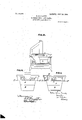
- Figure I is a top plan view of my improvements in cooking stoves showing the reduced combustion chamber, fire pot, and sliding draft regulator.
- Fig: II. is a section of the same along line a:x in Fig: I showing the reduced combustion chamber, inclosed air chamber, fire pot, and shaking grate with mechanism for operating the same, all in vertical section in position on the stove top.
- III. is a front view of a cooking stove .wit
- Fig: IV. is an end elevation of one end of my new or improved portable reduced stove showing the independent chimney, and the air inlets for the incoming air.
- Fig: V. is an elevation with portion broken away of the other end of my new or improved reduced stove, showing the hot air channel round the top of the fire box for heating the incoming air, and the slidingdoor for the insertion of a poker to operate the shaking grate.
- Fig: VI is asimilarview to FigzIII but with the front of the stove cut away to show the reduced stove in position in the fire box of an ordinarycooking stove- Similar letters of reference indicate similar parts in all the drawings.
- the reduced stove consists of two principa chambers, the combustion chamber A and the inclosedair chamber B separatedthe one from the other bythe horizontal diaphragm C and the partition wall D Fig: II. .
- a circular hole or opening is provided at one end of the horizontal diaphragm into which sits a small circular fire pot E tapering from top to bottom so as to fit tightly into the hole.
- the horizontal shakin My invention relates to a portable reduced 'or rocking grate.
- (6) Figs: I and II an through it and the fire pot E is the only means of communication between the air chamber B and the combustion chamber A.
- the air chamber B extends under the small fire pot E'as shown in Fig. II. It must be deep enough to allow of the free circulation of the air, and to provide a suitable ash pit immediately under the fire pot E, said ash pit being provided with a slide (6) Figs. II and V at the bottom to permit'of the ashes being removed.
- the end of the air chamber B immediately under the fire ot E extends upwards into a wide air duct T which being close to the fire pot E tends to heat the incoming air, as shown in Fig. II.
- An additional air channel or duct F Figs. II and V running round the top of the reduced fire 'box may-also be added, air being admitted thereto by means of the openings F F Fig. IV.
- the incoming air traverses the air duct or channel F along the back and front of the reduced fire box and enters the upper extension B of the ,air chamber B and is then drawn down and into the fire, and, by the time it reaches this point is already considerablyheated.
- the 0 ening G- at the op 0- site end of the reduced fire box A Fig. l is normally closed a sliding door, which when open allows a poker to be inserted to engage with and operate the rockin grate lever H.
- This opening G may be le t open for the more direct admission of the air to the air chamber B when it is not desired to use the air .heating ducts or channels F.
- Air may also be admitted to the air chamber ,B by means of auxiliary air ductsI as shown in Fig. II.
- auxiliary air ductsI may be laced in any position against the inside of t e reduced fire box and may be arranged to take the outside air either from the top sides or ends of the reduced fire box and by passes throu h the ducts or channels.
- At one en of the combustion chamber A to carry off the combustion gases'the floor of the combustion chamber adjacent to this auxiliary chimney may also be cut away to still further facilitate the escapeof the smoke and the combustion gases through the stove upon which the reduced stove sets, into the regular chimney.
- Thefire pot E is aflaring cylinder open at both ends, it fits tightly into the circular hole-or o ening inthe horizontal diaphragm C.
- the fire pot being small and only holding a small quantity of fuel is very economical it does not heat the room but places the heat just where it is Wanted directly under the kettle or vessel; and when not required, the Whole apparatus can be lifted from the stove and the ordinary stove plates and bridge replaced.
- a portable reduced stove adapted to be inserted into the fire box of a cooking stove or range from above, comprising in combination the long shallow combustion chamber A running the whole length of the top of the reduced )ortable stove, an incloscd air chamber under one end of said combustion chamber, a horizontal diaphragm C between the said combustion and air chambers, provided with an opening in which sets a plain tapered fire pot E; and closed air channels B and F for conveying the outside air to the air chamber under the fire pot, the whole combined and operating substantially as hereinbefore described.
Landscapes
- Engineering & Computer Science (AREA)
- Food Science & Technology (AREA)
- Chemical & Material Sciences (AREA)
- Combustion & Propulsion (AREA)
- Mechanical Engineering (AREA)
- General Engineering & Computer Science (AREA)
- Cookers (AREA)
- Solid-Fuel Combustion (AREA)
Description
No. 894,432. PATENTED JULY 28, 1908. R. N. GRUNDY.
COOKING STOVE AND RANGE.
APPLICATION FILED PEB.6.1907.
2 SHEETS-SHEET 1.
Witnesses: 1 v w MM fiwmauw nventor.
No. 894,432. PATENTED JULY 2a, 1908.
' R. N. GRUNDY.
COOKING STOVE AND RANGE. APPLICATION FILED PEB.6,1907.
z'snnnws-snsm 2.
I I FIG-v.
l v Y z Inventor TanbJhhmLvw Attorney v UNITED STATES ROBERT N'ELSONGRUNDY, OF GUELPH, ONTARIO, CANADA.
' COOKING STOVE AND RANGE.
Specification-of Letters Patent.
Patented July as, 1908.
Application fi1ed February,6, 1907. Serial No. 356,115.
To all whom it may concern:
Be it known that I, ROBERT NELsoN GRUNDY, a subject of His Majesty KingEd ward VII, of Great Britain, residin' atthe city of Guelph, in the county of We lin ton and Province of Ontario, Dominion of anada, have invented certain new and useful Improvements in Cooking Stoves and Ranges, of which the following is a, specification. Y
stove to be inserted into the fire boxof an ordinary cooking stove or range from above combustion chamber-a small flarin'g fire pot fitting into a circular opening in the horizontal diaphragm dividing the two chambers, and forming the only means of communication between them. attain these objects by the mechanism illustrated in the accompanying drawings, in which: I
Figure I. isa top plan view of my improvements in cooking stoves showing the reduced combustion chamber, fire pot, and sliding draft regulator. Fig: II. is a section of the same along line a:x in Fig: I showing the reduced combustion chamber, inclosed air chamber, fire pot, and shaking grate with mechanism for operating the same, all in vertical section in position on the stove top.
III. is a front view of a cooking stove .wit
my new or improved reduced portable stove in position. Fig: IV. is an end elevation of one end of my new or improved portable reduced stove showing the independent chimney, and the air inlets for the incoming air. Fig: V. is an elevation with portion broken away of the other end of my new or improved reduced stove, showing the hot air channel round the top of the fire box for heating the incoming air, and the slidingdoor for the insertion of a poker to operate the shaking grate. Fig: VI is asimilarview to FigzIII but with the front of the stove cut away to show the reduced stove in position in the fire box of an ordinarycooking stove- Similar letters of reference indicate similar parts in all the drawings. p
The reduced stove consists of two principa chambers, the combustion chamber A and the inclosedair chamber B separatedthe one from the other bythe horizontal diaphragm C and the partition wall D Fig: II. .A circular hole or opening is provided at one end of the horizontal diaphragm into which sits a small circular fire pot E tapering from top to bottom so as to fit tightly into the hole.
At the bottom of the fire pot E but not r 1 touching the'same is the horizontal shakin My invention relates to a portable reduced 'or rocking grate. (6) Figs: I and II an through it and the fire pot E is the only means of communication between the air chamber B and the combustion chamber A.
The air chamber B extends under the small fire pot E'as shown in Fig. II. It must be deep enough to allow of the free circulation of the air, and to provide a suitable ash pit immediately under the fire pot E, said ash pit being provided with a slide (6) Figs. II and V at the bottom to permit'of the ashes being removed. The end of the air chamber B immediately under the fire ot E extends upwards into a wide air duct T which being close to the fire pot E tends to heat the incoming air, as shown in Fig. II. An additional air channel or duct F Figs. II and V running round the top of the reduced fire 'box may-also be added, air being admitted thereto by means of the openings F F Fig. IV. The incoming air traverses the air duct or channel F along the back and front of the reduced fire box and enters the upper extension B of the ,air chamber B and is then drawn down and into the fire, and, by the time it reaches this point is already considerablyheated. The 0 ening G- at the op 0- site end of the reduced fire box A Fig. l is normally closed a sliding door, which when open allows a poker to be inserted to engage with and operate the rockin grate lever H. This opening G may be le t open for the more direct admission of the air to the air chamber B when it is not desired to use the air .heating ducts or channels F. Air may also be admitted to the air chamber ,B by means of auxiliary air ductsI as shown in Fig. II. These auxiliary air ducts Imay be laced in any position against the inside of t e reduced fire box and may be arranged to take the outside air either from the top sides or ends of the reduced fire box and by passes throu h the ducts or channels.
At one en of the combustion chamber A to carry off the combustion gases'the floor of the combustion chamber adjacent to this auxiliary chimney may also be cut away to still further facilitate the escapeof the smoke and the combustion gases through the stove upon which the reduced stove sets, into the regular chimney. This opening-is covered with a sliding plate J controlled by the rod K which projects through the wall of the fire box Figs. I and II.
Thefire pot E is aflaring cylinder open at both ends, it fits tightly into the circular hole-or o ening inthe horizontal diaphragm C.
As wil readily be understood the fire pot being small and only holding a small quantity of fuel is very economical it does not heat the room but places the heat just where it is Wanted directly under the kettle or vessel; and when not required, the Whole apparatus can be lifted from the stove and the ordinary stove plates and bridge replaced.
I am aware that efforts have been made to reduce the area of the fire chambers of stoves by means of fire bricks or movable vertical partitions, but these are necessarily clumsy and difficult of adjustment; whereas my device is compact, effective and easily lifted into or out of position.
What I claim and desire to secure Letters Patent for is: V.
A portable reduced stove adapted to be inserted into the fire box of a cooking stove or range from above, comprising in combination the long shallow combustion chamber A running the whole length of the top of the reduced )ortable stove, an incloscd air chamber under one end of said combustion chamber, a horizontal diaphragm C between the said combustion and air chambers, provided with an opening in which sets a plain tapered fire pot E; and closed air channels B and F for conveying the outside air to the air chamber under the lire pot, the whole combined and operating substantially as hereinbefore described.
ROBERT NELSON GRUNDY.
Witnesses SAMUEL TERRELL, D. H. BARLOW.
Priority Applications (1)
| Application Number | Priority Date | Filing Date | Title |
|---|---|---|---|
| US35611507A US894432A (en) | 1907-02-06 | 1907-02-06 | Cooking stove and range. |
Applications Claiming Priority (1)
| Application Number | Priority Date | Filing Date | Title |
|---|---|---|---|
| US35611507A US894432A (en) | 1907-02-06 | 1907-02-06 | Cooking stove and range. |
Publications (1)
| Publication Number | Publication Date |
|---|---|
| US894432A true US894432A (en) | 1908-07-28 |
Family
ID=2962859
Family Applications (1)
| Application Number | Title | Priority Date | Filing Date |
|---|---|---|---|
| US35611507A Expired - Lifetime US894432A (en) | 1907-02-06 | 1907-02-06 | Cooking stove and range. |
Country Status (1)
| Country | Link |
|---|---|
| US (1) | US894432A (en) |
Cited By (3)
| Publication number | Priority date | Publication date | Assignee | Title |
|---|---|---|---|---|
| US4335702A (en) * | 1979-08-22 | 1982-06-22 | Jarboe Joseph E | Woodburning stove |
| US20140123972A1 (en) * | 2012-11-06 | 2014-05-08 | EnviroFit International, Ltd. | High efficiency wood-burning griddle cook stove |
| US20170079460A1 (en) * | 2015-09-18 | 2017-03-23 | David Gordon Steputis | Heating and cooking system |
-
1907
- 1907-02-06 US US35611507A patent/US894432A/en not_active Expired - Lifetime
Cited By (4)
| Publication number | Priority date | Publication date | Assignee | Title |
|---|---|---|---|---|
| US4335702A (en) * | 1979-08-22 | 1982-06-22 | Jarboe Joseph E | Woodburning stove |
| US20140123972A1 (en) * | 2012-11-06 | 2014-05-08 | EnviroFit International, Ltd. | High efficiency wood-burning griddle cook stove |
| US20170079460A1 (en) * | 2015-09-18 | 2017-03-23 | David Gordon Steputis | Heating and cooking system |
| US10165888B2 (en) * | 2015-09-18 | 2019-01-01 | David Gordon Steputis | Heating and cooking system |
Similar Documents
| Publication | Publication Date | Title |
|---|---|---|
| US894432A (en) | Cooking stove and range. | |
| US1350495A (en) | Fireplace | |
| US293057A (en) | millee | |
| US665436A (en) | Heating-stove. | |
| US781309A (en) | Heating-stove. | |
| US392899A (en) | Stove or furnace | |
| US1938462A (en) | Movable stove | |
| US1127652A (en) | Cooking-stove. | |
| US870686A (en) | Stove. | |
| US135278A (en) | Improvement in base-burning fire-place heaters | |
| US89248A (en) | Improvement in base-burning stoves | |
| US777187A (en) | Stove. | |
| US488665A (en) | seebold | |
| US658696A (en) | Continuous-combustion stove. | |
| US226201A (en) | Heating-stove | |
| US31892A (en) | Furnace fob heating buildings | |
| US6083A (en) | Cooking-stove | |
| US595378A (en) | Heating apparatus | |
| US507017A (en) | Stove or furnace | |
| US764683A (en) | Magazine for heating stoves or furnaces. | |
| US401888A (en) | John h | |
| US738069A (en) | Heating-stove. | |
| US85255A (en) | Improvement in fire-place heaters | |
| US686091A (en) | Stove. | |
| US181942A (en) | Improvement in base-heating stoves |