US8202666B2 - Unit cell assembly, fuel cell, and method for manufacturing unit cell assembly - Google Patents
Unit cell assembly, fuel cell, and method for manufacturing unit cell assembly Download PDFInfo
- Publication number
- US8202666B2 US8202666B2 US12/418,782 US41878209A US8202666B2 US 8202666 B2 US8202666 B2 US 8202666B2 US 41878209 A US41878209 A US 41878209A US 8202666 B2 US8202666 B2 US 8202666B2
- Authority
- US
- United States
- Prior art keywords
- unit cell
- separator
- region
- cell assembly
- manifold
- Prior art date
- Legal status (The legal status is an assumption and is not a legal conclusion. Google has not performed a legal analysis and makes no representation as to the accuracy of the status listed.)
- Expired - Fee Related, expires
Links
Images


Classifications
-
- H—ELECTRICITY
- H01—ELECTRIC ELEMENTS
- H01M—PROCESSES OR MEANS, e.g. BATTERIES, FOR THE DIRECT CONVERSION OF CHEMICAL ENERGY INTO ELECTRICAL ENERGY
- H01M8/00—Fuel cells; Manufacture thereof
- H01M8/02—Details
- H01M8/0202—Collectors; Separators, e.g. bipolar separators; Interconnectors
- H01M8/0204—Non-porous and characterised by the material
- H01M8/0221—Organic resins; Organic polymers
-
- H—ELECTRICITY
- H01—ELECTRIC ELEMENTS
- H01M—PROCESSES OR MEANS, e.g. BATTERIES, FOR THE DIRECT CONVERSION OF CHEMICAL ENERGY INTO ELECTRICAL ENERGY
- H01M8/00—Fuel cells; Manufacture thereof
- H01M8/02—Details
- H01M8/0271—Sealing or supporting means around electrodes, matrices or membranes
- H01M8/0273—Sealing or supporting means around electrodes, matrices or membranes with sealing or supporting means in the form of a frame
-
- H—ELECTRICITY
- H01—ELECTRIC ELEMENTS
- H01M—PROCESSES OR MEANS, e.g. BATTERIES, FOR THE DIRECT CONVERSION OF CHEMICAL ENERGY INTO ELECTRICAL ENERGY
- H01M8/00—Fuel cells; Manufacture thereof
- H01M8/02—Details
- H01M8/0271—Sealing or supporting means around electrodes, matrices or membranes
- H01M8/028—Sealing means characterised by their material
- H01M8/0282—Inorganic material
-
- H—ELECTRICITY
- H01—ELECTRIC ELEMENTS
- H01M—PROCESSES OR MEANS, e.g. BATTERIES, FOR THE DIRECT CONVERSION OF CHEMICAL ENERGY INTO ELECTRICAL ENERGY
- H01M8/00—Fuel cells; Manufacture thereof
- H01M8/02—Details
- H01M8/0271—Sealing or supporting means around electrodes, matrices or membranes
- H01M8/028—Sealing means characterised by their material
- H01M8/0284—Organic resins; Organic polymers
-
- H—ELECTRICITY
- H01—ELECTRIC ELEMENTS
- H01M—PROCESSES OR MEANS, e.g. BATTERIES, FOR THE DIRECT CONVERSION OF CHEMICAL ENERGY INTO ELECTRICAL ENERGY
- H01M8/00—Fuel cells; Manufacture thereof
- H01M8/02—Details
- H01M8/0271—Sealing or supporting means around electrodes, matrices or membranes
- H01M8/0286—Processes for forming seals
-
- Y—GENERAL TAGGING OF NEW TECHNOLOGICAL DEVELOPMENTS; GENERAL TAGGING OF CROSS-SECTIONAL TECHNOLOGIES SPANNING OVER SEVERAL SECTIONS OF THE IPC; TECHNICAL SUBJECTS COVERED BY FORMER USPC CROSS-REFERENCE ART COLLECTIONS [XRACs] AND DIGESTS
- Y02—TECHNOLOGIES OR APPLICATIONS FOR MITIGATION OR ADAPTATION AGAINST CLIMATE CHANGE
- Y02E—REDUCTION OF GREENHOUSE GAS [GHG] EMISSIONS, RELATED TO ENERGY GENERATION, TRANSMISSION OR DISTRIBUTION
- Y02E60/00—Enabling technologies; Technologies with a potential or indirect contribution to GHG emissions mitigation
- Y02E60/30—Hydrogen technology
- Y02E60/50—Fuel cells
-
- Y—GENERAL TAGGING OF NEW TECHNOLOGICAL DEVELOPMENTS; GENERAL TAGGING OF CROSS-SECTIONAL TECHNOLOGIES SPANNING OVER SEVERAL SECTIONS OF THE IPC; TECHNICAL SUBJECTS COVERED BY FORMER USPC CROSS-REFERENCE ART COLLECTIONS [XRACs] AND DIGESTS
- Y02—TECHNOLOGIES OR APPLICATIONS FOR MITIGATION OR ADAPTATION AGAINST CLIMATE CHANGE
- Y02P—CLIMATE CHANGE MITIGATION TECHNOLOGIES IN THE PRODUCTION OR PROCESSING OF GOODS
- Y02P70/00—Climate change mitigation technologies in the production process for final industrial or consumer products
- Y02P70/50—Manufacturing or production processes characterised by the final manufactured product
-
- Y—GENERAL TAGGING OF NEW TECHNOLOGICAL DEVELOPMENTS; GENERAL TAGGING OF CROSS-SECTIONAL TECHNOLOGIES SPANNING OVER SEVERAL SECTIONS OF THE IPC; TECHNICAL SUBJECTS COVERED BY FORMER USPC CROSS-REFERENCE ART COLLECTIONS [XRACs] AND DIGESTS
- Y10—TECHNICAL SUBJECTS COVERED BY FORMER USPC
- Y10T—TECHNICAL SUBJECTS COVERED BY FORMER US CLASSIFICATION
- Y10T29/00—Metal working
- Y10T29/49—Method of mechanical manufacture
- Y10T29/49002—Electrical device making
- Y10T29/49108—Electric battery cell making
- Y10T29/4911—Electric battery cell making including sealing
-
- Y—GENERAL TAGGING OF NEW TECHNOLOGICAL DEVELOPMENTS; GENERAL TAGGING OF CROSS-SECTIONAL TECHNOLOGIES SPANNING OVER SEVERAL SECTIONS OF THE IPC; TECHNICAL SUBJECTS COVERED BY FORMER USPC CROSS-REFERENCE ART COLLECTIONS [XRACs] AND DIGESTS
- Y10—TECHNICAL SUBJECTS COVERED BY FORMER USPC
- Y10T—TECHNICAL SUBJECTS COVERED BY FORMER US CLASSIFICATION
- Y10T29/00—Metal working
- Y10T29/49—Method of mechanical manufacture
- Y10T29/49002—Electrical device making
- Y10T29/49108—Electric battery cell making
- Y10T29/49114—Electric battery cell making including adhesively bonding
Definitions
- the invention relates to a fuel cell and to a manufacturing method thereof.
- Fuel cells are provided with, for instance, unit cell constituent members, having each a substantially plate-like membrane electrode assembly (MEA), that are alternatively stacked with separators (see Japanese Patent Application Publication No. 2007-149393 (JP-A-2007-149393)).
- MEA substantially plate-like membrane electrode assembly
- the fuel cell stack may slip, for instance owing to external forces, deterioration or the like, and neighboring separators may come into contact with each other, giving rise to short circuits. Short circuits may result in various problems such as loss of power generation efficiency in the fuel cell.
- the invention suppresses short circuits that occur in a fuel cell when separators come into contact with each other.
- a first aspect of the invention relates to a unit cell assembly stacked in a plurality to form a fuel cell.
- the unit cell assembly has a separator; a unit cell constituent member disposed at a first region on one face of the separator; a seal member, which is formed of an elastic member and bonded to a second region surrounding the first region on one face of the separator, and which is integrated with at least part of a peripheral edge of the unit cell constituent member; and a first insulating portion having insulating properties and provided at least on part of a peripheral edge of the separator.
- Short circuits occurring when separators come into contact with each other can be prevented in a fuel cell that has a stack of a plurality of such unit cell assemblies.
- the first insulating portion may be provided at an edge face of the separator.
- Short circuits caused by contact between separators in a fuel cell can be suppressed thereby.
- the seal member may have, as the first insulating portion, a first covering portion that covers an edge face at a peripheral edge of the separator.
- Short circuits caused by contact between separators in a fuel cell can be suppressed thereby at the same time that the number of parts in the fuel cell is reduced.
- the first insulating portion may be a cap-like member that covers an edge face at a peripheral edge of the separator.
- an insulating portion can be easily formed on the separator, and slippage of the unit cell assembly stack in the fuel cell can also be prevented.
- the separator may have a conductive plate-like member and a resinous plate-like member formed of a resin; and the resinous plate-like member may have a second covering portion, as the first insulating portion, that covers an edge face of the conductive plate-like at a peripheral edge of the separator.
- Short circuits caused by contact between separators in a fuel cell can be suppressed thereby at the same time that the number of parts in the fuel cell is reduced.
- the first insulating portion may be an oxidatively-treated portion formed by subjecting the separator to an oxidative treatment.
- Short circuits caused by contact between separators in a fuel cell can be suppressed thereby at the same time that the number of parts in the fuel cell is reduced.
- the first insulating portion may be formed through coating with alumina or magnesia.
- the insulating portion can be easily formed thereby on the separator.
- the first insulating portion may have a first projection extending in a thickness direction of the unit cell assembly.
- the separator may have a manifold, which extends through a thickness direction of the unit cell assembly, and through which a reactant gas or a cooling medium flows; and the unit cell assembly may have a second insulating portion optionally having insulating properties and provided at a peripheral edge of the manifold of the separator.
- Short circuits caused by contact between separators in a fuel cell can be suppressed thereby.
- the second insulating portion may have a second projection extending in a thickness direction of the unit cell assembly.
- a second aspect of the invention relates to a unit cell assembly stacked in a plurality to form a fuel cell.
- the unit cell assembly has a separator provided with a manifold which extends through a thickness direction of the unit cell assembly, and through which a reactant gas or a cooling medium flows; a unit cell constituent member disposed on one face of the separator at a first region; a seal member, which is formed of an elastic member and bonded to a second region surrounding the first region on one face of the separator, and which is integrated with at least part of a peripheral edge of the unit cell constituent member; and a manifold insulating portion having insulating properties and provided at least on part of a peripheral edge of the manifold of the separator.
- Short circuits caused by contact between separators in a fuel cell can be suppressed thereby.
- a third aspect of the invention relates to a fuel cell resulting from stacking a plurality of unit cell assemblies according to the first aspect or the second aspect.
- Short circuits caused by contact between separators can be suppressed in such a fuel cell.
- a fourth aspect of the invention relates to a method for manufacturing a unit cell assembly in which a separator and a unit cell constituent member are stacked.
- This method for manufacturing a unit cell assembly includes the steps of arranging the unit cell constituent member on one face of the separator at a first region; molding a seal member formed of an elastic member to be bonded to a second region surrounding the first region on one face of the separator, and to be integrated with a peripheral edge of the unit cell constituent member; and providing an insulating portion at a peripheral edge of the separator.
- This method for manufacturing a unit cell assembly allows manufacturing a unit cell assembly in which an insulating portion is provided at a peripheral edge of a separator. Short circuits caused by contact between separators can be suppressed in a fuel cell having a stack of a plurality of unit cell assemblies thus manufactured.
- a fifth aspect of the invention relates to a method for manufacturing a unit cell assembly in which a separator and a unit cell constituent member are stacked.
- This method for manufacturing a unit cell assembly includes the steps of arranging the separator in a mold; arranging the unit cell constituent member at a first region on one face of the separator; molding a seal member through injection molding or compression molding of a molding material in a space that is demarcated by a second region surrounding the first region on one face of the separator, a peripheral edge of the unit cell constituent member, and the mold; and providing an insulating portion at a peripheral edge of the separator.
- This method for manufacturing a unit cell assembly allows manufacturing a unit cell assembly in which an insulating portion is provided at a peripheral edge of a separator. Short circuits caused by contact between separators can be suppressed in a fuel cell having a stack of a plurality of unit cell assemblies thus manufactured.
- the invention is not limited to the above-described fuel cell manufacturing method, and may be realized as aspects of other invention methods, such as a method for manufacturing a separator or a unit cell assembly.
- the invention is not limited to a fuel cell, and may be realized in other aspects, such as a separator or a unit cell assembly.
- FIG. 1 is an illustrative diagram depicting the construction of a fuel cell 100 in a first embodiment
- FIG. 2 is a side-view diagram of unit cell assemblies 200 that make up the fuel cell 100 ;
- FIG. 3 is a flowchart illustrating manufacturing steps of the fuel cell in the first embodiment
- FIG. 4 is a diagram illustrating a front view of a unit cell assembly 200 (viewed from the right side in FIG. 2 );
- FIG. 5 is a cross-sectional diagram illustrating a cross section V-V in FIG. 4 ;
- FIG. 6 is an illustrative diagram depicting the shape of a cathode plate 400 ;
- FIG. 7 is an illustrative diagram depicting the shape of an anode plate 300 ;
- FIG. 8 is an illustrative diagram depicting the shape of an intermediate plate 500 ;
- FIG. 9 is a front-view diagram of a separator
- FIGS. 10A and 10B are illustrative diagrams showing the flow of reactant gases in the fuel cell
- FIG. 11 is a flowchart outlining the manufacturing steps of a unit cell assembly in the first embodiment
- FIGS. 12A and 12B are diagrams for illustrating a molding step during the manufacture of a unit cell assembly
- FIG. 13 is a diagram illustrating a mold
- FIG. 14 is an illustrative diagram depicting the construction of a unit cell assembly in a second embodiment
- FIG. 15 is an illustrative diagram depicting the construction of a unit cell assembly in a third embodiment
- FIG. 16 is an illustrative diagram depicting the construction of a unit cell assembly in a fourth embodiment
- FIG. 17 is an illustrative diagram depicting the construction of a unit cell assembly in a fifth embodiment.
- FIG. 18 is an illustrative diagram depicting the construction of a unit cell assembly in a sixth embodiment.
- FIG. 1 is an illustrative diagram depicting the construction of a fuel cell 100 in the first embodiment.
- FIG. 2 is a side-view diagram of unit cell assemblies 200 that make up the fuel cell 100 .
- FIG. 3 is a flowchart illustrating the manufacturing steps of the fuel cell in the first embodiment.
- the unit cell assemblies 200 are depicted spaced apart from each other, although in actuality the unit cell assemblies 200 are contiguous to each other.
- the unit cell assemblies 200 illustrated in FIG. 2 are depicted each with a seal member 700 , a unit cell constituent member 800 , a power generation region DA and a surrounding region DR. These are described in detail below.
- the fuel cell 100 has a structure (called a stack structure) in which a plurality of unit cell assemblies 200 is stacked.
- the direction in which the unit cell assemblies 200 are stacked is called the stacking direction, while the direction perpendicular to the stacking direction and extending across the planes of the unit cell assemblies 200 is called the planar direction.
- the fuel cell 100 is manufactured by stacking a predetermined number of unit cell assemblies 200 (step S 102 ), and then fastening the unit cell assemblies 200 in the stacking direction by applying a predetermined fastening force (step S 104 ).
- the thickness direction of the below-described members that are provided in the unit cell assemblies 200 is substantially the same as the stacking direction.
- the fuel cell 100 has an oxidizing gas supply manifold 110 that is supplied with an oxidizing gas, an oxidizing gas discharge manifold 120 that discharges the oxidizing gas, a fuel gas supply manifold 130 that is supplied with a fuel gas, a fuel gas discharge manifold 140 that discharges the fuel gas, a cooling medium supply manifold 150 that supplies a cooling medium, and a cooling medium discharge manifold 160 that discharges the cooling medium.
- the fuel cell 100 generates electric power through supply of the oxidizing gas to the oxidizing gas supply manifold 110 and through supply of the fuel gas to the fuel gas supply manifold 130 .
- a cooling medium is supplied to the cooling medium supply manifold 150 in order to restrain the temperature rise of the fuel cell 100 , which is caused by the release of heat that accompanies power generation.
- air is used as the oxidizing gas, while hydrogen or the like is used as the fuel gas.
- the oxidizing gas and the fuel gas are also called reactant gases.
- the cooling medium there is used, for instance, water, an antifreeze liquid such as ethylene glycol, or air.
- FIG. 4 is a diagram illustrating a front view of a unit cell assembly 200 (viewed from the right side in FIG. 2 ).
- FIG. 5 is a cross-sectional diagram illustrating a cross section V-V in FIG. 4 .
- each unit cell assembly 200 has the separator 600 , the unit cell constituent member 800 and the seal member 700 .
- a surface located at the peripheral edge of the member and extending along the stacking direction will also be called an edge face.
- the end face of the separators 600 will also be called the edge face TM.
- Each separator 600 has an anode plate 300 , a cathode plate 400 , an intermediate plate 500 and a conductive porous member 555 .
- FIG. 6 is an illustrative diagram depicting the shape of the cathode plate 400 .
- FIG. 7 is an illustrative diagram depicting the shape of the anode plate 300 .
- FIG. 8 is an illustrative diagram depicting the shape of the intermediate plate 500 .
- FIGS. 6 to 8 depict the plates 400 , 300 and 500 viewed from the right side in FIG. 2 .
- a region DA in a central portion of each of the plates 300 , 400 , 500 denoted by a dashed line, is in the unit cell assemblies 200 a region corresponding to the region at which the unit cell constituent member 800 is disposed (referred to hereinafter as “power generation region DA”).
- the cathode plate 400 illustrated in FIG. 6 is formed, for example, of a stainless steel.
- the cathode plate 400 has six manifold-forming portions 422 to 432 , an oxidizing gas supply slit 440 , and an oxidizing gas discharge slit 444 .
- the manifold-forming portions 422 to 432 which are through-opening portions for forming the various manifolds during construction of the fuel cell 100 , are provided outside the power generation region DA.
- the oxidizing gas supply slit 440 is disposed at an end portion (upper end in FIG. 6 ) of the power generation region DA.
- the oxidizing gas discharge slit 444 is disposed at an end portion (lower end in FIG. 6 ) of the power generation region DA.
- the anode plate 300 is formed, for instance, of stainless steel, like the cathode plate 400 .
- the anode plate 300 is provided with six manifold-forming portions 322 to 332 , a fuel gas supply slit 350 , and a fuel gas discharge slit 354 .
- the manifold-forming portions 322 to 332 which are through-opening portions for forming the various manifolds during construction of the fuel cell 100 , are provided outside the power generation region DA.
- the fuel gas supply slit 350 is disposed at an end portion (lower end in FIG.
- the fuel gas discharge slit 354 is disposed at an end portion (upper end in FIG. 7 ) of the power generation region DA in such a manner that so as not to overlap with the oxidizing gas supply slit 440 in the cathode plate 400 during construction of the separator 600 .
- the intermediate plate 500 is formed of a laminate resin, unlike the plates 300 and 400 .
- laminate resins that can be used include, for instance, polyethylene terephthalate (PET), polypropylene (PP), polyethylene naphthalate (PEN) or Kapton film.
- the intermediate plate 500 has, as through-opening portions that run through the intermediate plate 500 in the thickness direction thereof, four manifold-forming portions 522 to 528 for supplying/discharging a reactant gas (the oxidizing gas or the fuel gas), supply channel-forming portions 542 , 546 , and discharge channel-forming portions 544 , 548 .
- a reactant gas the oxidizing gas or the fuel gas
- the intermediate plate 500 further includes, as a through-opening portion that runs substantially through the center of the plate, a cooling medium channel-forming portion 550 , as well as cooling medium supply slits 551 and cooling medium discharge slits 552 that communicate with the cooling medium channel-forming portion 550 .
- the manifold-forming portions 522 to 528 which are through-opening portions for forming the various manifolds during construction of the fuel cell 100 , are respectively provided outside the power generation region DA.
- the conductive porous member 555 is a porous member formed of a conductive material such as stainless steel and whose surface area in the planar direction is smaller than that of the cooling medium channel-forming portion 550 .
- the thickness of the conductive porous member 555 is substantially identical to the thickness of the intermediate plate 500 in the stacking direction.
- the conductive porous member 555 which is disposed at the cooling medium channel-forming portion 550 , has the functions of electrically connecting the cathode plate 400 and the anode plate 300 and of serving as a channel through which the cooling medium flows when the three plates 300 , 400 , 500 of the separator 600 are stacked up.
- the supply channel-forming portions 542 , 546 and the discharge channel-forming portions 544 , 548 for the reactant gases have each one end communicating with respective manifold forming portions 522 to 528 .
- the other ends of the channel-forming portions 542 , 544 , 546 , 548 communicate with respective gas supply/discharge slits 440 , 444 , 350 , 354 when the three plates 300 , 400 , 500 are joined.
- FIG. 9 is a front-view diagram of a separator.
- the separator 600 is manufactured by joining the anode plate 300 and the cathode plate 400 to both sides of the intermediate plate 500 , so as to sandwich the intermediate plate 500 , and by punching the portions of the intermediate plate 500 that are exposed to regions that correspond to the cooling medium supply manifold 150 and the cooling medium discharge manifold 160 .
- the three plates are stacked, and then the intermediate plate 500 is joined to the anode plate 300 , and the intermediate plate 500 to the cathode plate 400 , by hot pressing.
- a separator 600 is obtained having six manifolds 110 to 160 , as through-opening portions hatched in FIG.
- oxidizing gas supply channels 650 oxidizing gas discharge channels 660 , a fuel gas supply channel 630 , a fuel gas discharge channel 640 , and cooling medium channels 670 .
- the surfaces of the separator 600 that form the manifolds along the stacking direction and which communicate with the channels 630 to 670 are also called manifold inner-side-forming surfaces MUM.
- the surfaces of the separator 600 that form the manifolds along the stacking direction and that oppose the manifold inner-side-forming surfaces MUM are called manifold outer forming surfaces MSM.
- the oxidizing gas supply channels 650 are formed by the supply channel-forming portions 542 for oxidizing gas, which are formed in the intermediate plate 500 ( FIG. 8 ), and by the oxidizing gas supply slit 440 formed in the cathode plate 400 ( FIG. 6 ).
- the oxidizing gas discharge channels 660 are formed by the discharge channel-forming portions 544 for oxidizing gas, which are formed in the intermediate plate 500 ( FIG. 8 ), and by the oxidizing gas discharge slit 444 formed in the cathode plate 400 ( FIG. 6 ).
- the fuel gas supply channel 630 is formed by the supply channel-forming portion 546 for fuel gas, which is formed in the intermediate plate 500 ( FIG.
- the fuel gas discharge channel 640 is formed by the discharge channel-forming portion 548 for fuel gas, which is formed in the intermediate plate 500 ( FIG. 8 ), and by the fuel gas discharge slit 354 formed in the cathode plate 300 ( FIG. 7 ).
- the cooling medium channels 670 are formed by the cooling medium channel-forming portion 550 ( FIG. 8 ), the cooling medium supply slits 551 ( FIG. 8 ) and the cooling medium discharge slits 552 ( FIG. 8 ).
- the unit cell constituent member 800 is disposed at the power generation region DA, on the face of the separator 600 that is on the side of the cathode plate 400 .
- the seal member 700 is disposed on the same face of the separator 600 , at a region DR (hereinafter surrounding region DR) outside the power generation region DA. As illustrated in FIG. 2 , the unit cell constituent member 800 is disposed at the power generation region DA, on the face of the separator 600 that is on the side of the cathode plate 400 .
- the seal member 700 is disposed on the same face of the separator 600 , at a region DR (hereinafter surrounding region DR) outside the power generation region DA.
- DR hereinafter surrounding region DR
- the unit cell constituent member 800 has an MEA 810 , an anode-side diffusion layer 820 disposed in contact with the anode-side face of the MEA 810 , a cathode-side diffusion layer 830 in contact with the cathode-side face of the MEA 810 , an anode-side porous body 840 and a cathode-side porous body 850 .
- the anode-side porous body 840 is disposed flanking the anode-side diffusion layer 820 , on the anode side of the MEA 810 , while the cathode-side porous body 850 is disposed flanking the cathode-side diffusion layer 830 , on the cathode side of the MEA 810 .
- the cathode-side porous body 850 is in contact with the power generation region DA of the separator 600 .
- the anode-side porous body 840 comes into contact with the face of the separator 600 of another unit cell assembly 200 , on the side of the anode plate 300 of this other separator 600 .
- the MEA 810 has an ion exchange membrane formed, for instance, of a fluororesin material or a hydrocarbon resin material that has good ion conductivity in a moist state, and catalyst layers coated on both surfaces of the ion exchange membrane.
- the catalyst layers contain, for example, platinum, or an alloy of platinum with another metal.
- the anode-side diffusion layer 820 and the cathode-side diffusion layer 830 are formed of, for example, carbon paper, carbon felt or a carbon cloth formed by weaving yarns of carbon fiber.
- the anode-side porous body 840 and the cathode-side porous body 850 are formed of a porous material having gas diffusivity and electrical conductivity, such as a metal porous body.
- the anode-side porous body 840 and the cathode-side porous body 850 have higher porosity than the anode-side diffusion layer 820 and the cathode-side diffusion layer 830 , and have lower internal gas flow resistance than the anode-side diffusion layer 820 and the cathode-side diffusion layer 830 .
- the anode-side porous body 840 and the cathode-side porous body 850 function as channels for allowing the reactant gases to flow, as described below.
- the seal member 700 has a support portion 710 , a rib 720 , an outer covering portion 730 and inner covering portions 740 .
- the seal member 700 is formed of a material having gas impermeability, elasticity and heat resistance in the working temperature range of the fuel cell, for example, an elastic material such as rubber or an elastomer.
- an elastic material such as rubber or an elastomer.
- Specific materials that can be used include, for instance, silicone-based rubbers, butyl rubbers, acrylic rubbers, natural rubbers, fluorocarbon rubbers, ethylene/propylene-based rubbers, styrene-based elastomers, fluorocarbon elastomers and the like.
- the support portion 710 is in contact with the entire surrounding region DR on the surface of the separator 600 that is on the side of the cathode plate 400 (see FIGS. 2 and 5 ).
- the support portion 710 of the seal member 700 is bonded, with a predetermined bonding force, to the separator 600 at a contact surface SU (heavy line in FIG. 5 ) between the support portion 710 and the face of the separator 600 that is on the side of the cathode plate 400 .
- the “predetermined bonding force” denotes a bonding force at a state in which the unit cell assemblies 200 are not stacked/fastened, i.e. at a state in which no load is applied in the stacking direction.
- the bonding force of the contact surface SU may be of 0.01 N/mm (Newton per millimeter) or more per unit length of seal line, or of 0.6 N/mm or more.
- the support portion 710 is integrated with the unit cell constituent member 800 by being impregnated into the edge of the unit cell constituent member 800 , as indicated by the reference numeral BB in FIGS. 4 and 5 .
- reactant gases are prevented from leaking from the cathode side of the MEA 810 towards the anode side thereof, or from the anode side of the MEA 810 towards the cathode side thereof, at the edge of the unit cell constituent member 800 .
- the rib 720 is formed on the upper portion of the support portion 710 in such a way so as to protrude from the support portion 710 in the stacking direction, as illustrated in FIG. 5 .
- the rib 720 is formed in such a way so as to surround the unit cell constituent member 800 and the manifolds 110 to 160 , as illustrated in FIG. 4 .
- the rib 720 is brought into airtight contact with the anode plate 300 of the separator 600 of another unit cell assembly 200 through the action of a fastening force in the stacking direction.
- the outer covering portion 730 is formed at the outer peripheral edge of the support portion 710 in such a way so as to cover the edge face TM of the separator 600 , as illustrated in FIG. 5 .
- the inner covering portions 740 are formed in such a way so as to cover the manifold outer forming surfaces MSM of the manifolds of the separator 600 , as illustrated in FIG. 5 .
- the seal member 700 is integrated with the unit cell constituent member 800 and the separator 600 .
- the separator 600 , the seal member 700 and the unit cell constituent member 800 are integrated together in the unit cell assembly 200 .
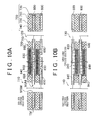
- FIGS. 10A and 10B are illustrative diagrams showing the flow of reactant gases in the fuel cell.
- FIGS. 10A and 10B illustrate a state of two stacked unit cell assemblies 200 .
- FIG. 10A illustrates a sectional view corresponding to the cross section XA-XA in FIG. 9 .
- the right half illustrates a sectional view corresponding to the cross section XB 2 -XB 2 in FIG. 9
- the left half illustrates a sectional view corresponding to the cross section XB 1 -XB 1 in FIG. 9 .
- the oxidizing gas supplied to the oxidizing gas supply manifold 110 is infused from the oxidizing gas supply manifold 110 into the cathode-side porous body 850 via the oxidizing gas supply channels 650 .
- the oxidizing gas supplied to the cathode-side porous body 850 flows from the top down in FIGS. 4 and 9 within the cathode-side porous body 850 that has the function of channeling the oxidizing gas.
- the oxidizing gas is discharged to the oxidizing gas discharge manifold 120 via the oxidizing gas discharge channels 660 .
- the fuel gas supplied to the fuel gas supply manifold 130 is infused from the fuel gas supply manifold 130 into the anode-side porous body 840 via the fuel gas supply channel 630 .
- the fuel gas supplied to the anode-side porous body 840 flows from the bottom up in FIGS. 4 and 9 within the anode-side porous body 840 that has the function of channeling the fuel gas.
- the fuel gas is discharged to the fuel gas discharge manifold 140 via the fuel gas discharge channel 640 .
- Part of the fuel gas flowing through the anode-side porous body 840 diffuses throughout the entire anode-side diffusion layer 820 that abuts the anode-side porous body 840 , to take part in the anode reaction (for instance, H 2 ⁇ 2H + +2e ⁇ ).
- the cooling medium supplied to the cooling medium supply manifold 150 is supplied from the cooling medium supply manifold 150 into the cooling medium channels 670 .
- the cooling medium supplied to the cooling medium channels 670 flows from one end to the other end of the cooling medium channels 670 , and is discharged into the cooling medium discharge manifold 160 .
- the outer covering portion 730 is disposed in such a way so as to cover a peripheral edge of the separator 600 (cathode plate 400 or anode plate 300 ) that includes the edge face TM.
- the inner covering portions 740 are disposed in such a way so as to cover a manifold peripheral edge that includes the manifold outer forming surfaces MSM of the separator 600 (for instance, FIG. 5 , FIGS. 10A and 10B ).
- the outer covering portion 730 comes between the separators 600 even when the stack of unit cell assemblies 200 slips, and the separators 600 are brought close to each other on account of, for instance, external forces applied to the fuel cell 100 or on account of deterioration of the seal member 700 .
- the separators 600 can be prevented from coming into direct contact with each other. This allows suppressing the occurrence of short circuits caused by contact between the separators 600 , and allows curtailing drops in power generation efficiency in the fuel cell 100 .
- the MEA 810 , the seal member 700 and the separator 600 are integrally formed together. This allows enhancing assemblability and handleability during stacking of the unit cell assemblies 200 , while reducing the number of manufacturing steps during the manufacture of the fuel cell 100 .
- FIG. 11 is a flowchart outlining the manufacturing steps of a unit cell assembly in the embodiment.
- FIGS. 12A and 12B are diagrams for illustrating a molding step during the manufacture of the unit cell assembly.
- FIG. 13 is a diagram illustrating a mold.
- FIGS. 12A and 12B correspond to the cross section XII-XII of FIG. 13 .
- a mold for integrative molding is prepared first (step S 202 ).
- the mold has an upper die 910 and a lower die 920 .
- the lower die 920 has protrusions 920 A for positioning the separator 600 .
- the upper die 910 has fitting portions 910 A that fit with the protrusion 920 A, as well as feed ports SH and communicating ports RH for the molding material.
- the separator 600 is disposed next on the lower die 920 (step S 204 ).
- the separator 600 can be positioned by arranging the separator 600 in such a manner that the manifold inner-side-forming surfaces MUM of the separator 600 abut the protrusions 920 A.
- the separator 600 is disposed on the lower die 920 with the side of the anode plate 300 facing down and the side of the cathode plate 400 facing up.
- the cathode-side porous body 850 is disposed on the separator 600 that is arranged on the lower die 920 (step S 206 ).
- the cathode-side porous body 850 is disposed at the power generation region DA ( FIG. 6 and so forth), on the face of the separator 600 that is on the side of the cathode plate 400 .
- a MEGA 860 is stacked then on the arranged cathode-side porous body 850 (step S 208 ).
- the MEGA 860 has been obtained by hot pressing beforehand the anode-side diffusion layer 820 and the cathode-side diffusion layer 830 against both faces of the MEA 810 .
- the anode-side porous body 840 is stacked then on the arranged MEGA 860 (step S 210 ).
- FIG. 12B illustrates the lower die 920 and the upper die 910 when clamped.
- a space SP having the shape of the seal member 700 of the unit cell assembly 200 is formed over the surrounding region DR of the face of the separator 600 on the side of the cathode plate 400 . As illustrated in FIG.
- the space SP is demarcated by the face of the separator 600 on the side of the cathode plate 400 , the inner wall faces of the lower die 920 and the upper die 910 , and the edge of the unit cell constituent member 800 (anode-side porous body 840 , MEGA 860 and cathode-side porous body 850 ).
- Injection molding is performed in this space SP. Specifically, liquid rubber, as the molding material of the seal member 700 , is injected into the space SP via the feed ports SH, and is then vulcanized.
- the communicating ports RH have the function of allowing the molding material, which is fed via the feed ports SH, to get into the space SP.
- the feeding pressure of the molding material during injection molding is controlled in such a manner that the edge of the unit cell constituent member 800 becomes impregnated with the molding material (see region BB in FIGS. 4 and 5 ), whereby the unit cell constituent member 800 and the seal member 700 become integrated together.
- the bonding force at the contact surface SU ( FIG. 5 ) between the seal member 700 and the separator 600 is ensured by adding a silane coupling agent to the molding material.
- the mold is opened to yield a unit cell assembly 200 in which the seal member 700 , the unit cell constituent member 800 and the separator 600 are integrated together.
- the edge face TM of the separator 600 is pressed against the molds to position thereby the separator 600 by way of the edge face TM.
- the separator 600 is positioned by way of the manifold inner-side-forming surfaces MUM of the separator 600 . Doing so allows creating a space, between the edge face TM of the separator 600 and the molds, into which the molding material can be fed.
- the outer covering portion 730 made of the molding material, can be formed as a result at the edge face TM of the separator 600 .
- the separator 600 corresponds to the separator
- the power generation region DA corresponds to the first region
- the surrounding region DR corresponds to the second region
- the unit cell constituent member 800 corresponds to the unit cell constituent member
- the seal member 700 corresponds to the seal member
- the outer covering portion 730 corresponds to the first insulating portion or the first covering portion
- the inner covering portions 740 correspond to the second insulating portion or the manifold insulating portion.
- FIG. 14 is an illustrative diagram depicting the construction of a unit cell assembly in a second embodiment.
- a unit cell assembly 200 A of the second embodiment illustrated in FIG. 14 elements identical to those of the unit cell assembly 200 of the first embodiment are denoted with the same reference numerals, and explanations thereof are omitted.
- the manifold outer forming surfaces MSM the portions corresponding to the anode plate 300 are referred to as manifold outer forming surfaces MSM 1
- the portions corresponding to the cathode plate 400 are referred to as manifold outer forming surfaces MSM 2 .
- the edge faces of the anode plate 300 and the cathode plate 400 are referred to as edge face TM 1 and edge face TM 2 , respectively.
- a seal member 700 A lacks the outer covering portion 730 and the inner covering portions 740 , and the shape of a separator 600 A is different from that of the separator 600 , as illustrated in FIG. 14 .
- part of an intermediate plate 500 A forms a covering portion 510 A and a covering portion 520 A.
- the covering portion 510 A is disposed and fixed in such a way so as to enfold the peripheral edge of the anode plate 300 and the cathode plate 400 , so that the covering portion 510 A covers the edge faces TM 1 , TM 2 of the anode plate 300 and the cathode plate 400 .
- the covering portions 520 A are disposed and fixed in such a way so as to enfold the peripheral edge of the anode plate 300 and the cathode plate 400 , so that the covering portion 520 A covers the manifold outer forming surfaces MSM 1 , MSM 2 of the anode plate 300 and the cathode plate 400 .
- the covering portion 510 A and the covering portion 520 A which are part of the intermediate plate 500 A, are used as short-circuit preventing members that prevent shorting between separators, instead of the outer covering portion 730 and the inner covering portions 740 of the first embodiment.
- the second embodiment affords thereby the same effect as the first embodiment, but without the need for providing the outer covering portion 730 and the inner covering portions 740 in the seal member.
- the seal member can thus be shaped easily, and the molding material can likewise be injection-molded easily.
- the anode plate 300 and the cathode plate 400 correspond to the conductive plate-like member of the invention
- the intermediate plate 500 A corresponds to the resinous plate-like member
- the covering portion 510 A corresponds to the first insulating portion or the second covering portion
- the covering portions 520 A correspond to the second insulating portion or the manifold insulating portion.
- FIG. 15 is an illustrative diagram depicting the construction of a unit cell assembly in a third embodiment.
- a unit cell assembly 200 B of the third embodiment illustrated in FIG. 15 elements identical to those of the unit cell assembly 200 of the first embodiment are denoted with the same reference numerals, and explanations thereof are omitted.
- a seal member 700 B lacks the outer covering portion 730 and the inner covering portions 740 but is provided with insulating cap-like members 771 , 772 , as illustrated in FIG. 15 .
- the insulating cap-like member 771 is disposed in such a way so as to cover a peripheral edge of the separator 600 that includes the edge face TM.
- the insulating cap-like members 772 are disposed in such a way so as to cover manifold peripheral edges including the manifold outer forming surfaces MSM of the separator 600 .
- the insulating cap-like members 771 , 772 are used as short circuit preventing members that prevent shorting between separators, instead of the outer covering portion 730 and the inner covering portions 740 of the first embodiment.
- the third embodiment affords thereby the same effect as the first embodiment, but without the need for providing the outer covering portion 730 and the inner covering portions 740 in the seal member.
- the molding material can thus be shaped easily, and injection molding of the seal member can likewise be carried out easily.
- the insulating cap-like member 771 or the insulating cap-like members 772 may also be made thicker, to a thickness comparable to that of the support portion 710 . This allows using the insulating cap-like members for positioning and preventing slippage of the stack of unit cell assemblies 200 B during stacking of the unit cell assemblies 200 B in the manufacture of the fuel cell.
- the insulating cap-like member 771 corresponds to the first insulating portion or cap-like member of the invention.
- the insulating cap-like members 772 correspond to the second insulating portion.
- FIG. 16 is an illustrative diagram depicting the construction of a unit cell assembly in a fourth embodiment.
- a unit cell assembly 200 C of the fourth embodiment illustrated in FIG. 16 elements identical to those of the unit cell assembly 200 of the first embodiment are denoted with the same reference numerals, and explanations thereof are omitted.
- a seal member 700 C lacks the outer covering portion 730 and the inner covering portions 740 .
- the separator 600 B is provided with oxidatively-treated portions 773 .
- the oxidatively-treated portions 773 are formed by subjecting the separator to an oxidative treatment, at the surrounding region DR of the separator 600 B, on portions where the seal member 700 B is not formed in the planar direction of the separator 600 B, and on the edge face TM 1 , the edge face TM 2 , the manifold outer forming surfaces MSM 1 and the manifold outer forming surfaces MSM 2 .
- the oxidatively-treated portions 773 of the separator 600 B are used instead of the outer covering portion 730 and the inner covering portions 740 of the first embodiment.
- the fourth embodiment affords thereby the same effect as the first embodiment, without the need for providing short circuit preventing members that prevent shorting between separators. The number of parts can thus be reduced.
- the outer covering portion 730 and the inner covering portions 740 need not be provided in the seal member.
- the seal member can thus be shaped easily, and the molding material can likewise be injection-molded easily.
- the oxidatively-treated portions 773 correspond to the first insulating portion, the oxidatively-treated portion, the second insulating portion or the manifold insulating portion of the invention.
- FIG. 17 is an illustrative diagram depicting the construction of a unit cell assembly in a fifth embodiment.
- a unit cell assembly 200 D of the fifth embodiment illustrated in FIG. 17 elements identical to those of the unit cell assembly 200 of the first embodiment are denoted with the same reference numerals, and explanations thereof are omitted.
- a seal member 700 D lacks the outer covering portion 730 and the inner covering portions 740 .
- the separator 600 is coated with an insulating material 775 .
- the insulating material 775 is made of a material, such as alumina or magnesia, having insulating properties.
- the insulating material 775 is coated onto the peripheral edge of the separator 600 including the edge face TM, and the manifold peripheral edges including the manifold outer forming surfaces MSM of the separator 600 .
- the insulating material 775 is coated, as a short circuit preventing member that prevents shorting between separators, instead of the outer covering portion 730 and the inner covering portions 740 of the first embodiment.
- the fifth embodiment affords thereby the same effect as the first embodiment, but without the need for providing the outer covering portion 730 and the inner covering portions 740 in the seal member.
- the seal member can thus be shaped easily, and the molding material can likewise be injection-molded easily.
- the insulating material 775 that is coated corresponds to the first insulating portion, the second insulating portion or the manifold insulating portion of the invention.
- FIG. 18 is an illustrative diagram depicting the construction of a unit cell assembly in a sixth embodiment.
- a unit cell assembly 200 E of the sixth embodiment illustrated in FIG. 18 elements identical to those of the unit cell assembly 200 of the first embodiment are denoted with the same reference numerals, and explanations thereof are omitted.
- a seal member 700 E has a plurality of projections 777 extending in the stacking direction, as illustrated in FIG. 18 .
- the projections 777 are less high than the rib 720 , i.e. the projections 777 do not touch the separators 600 during stacking of the unit cell assemblies 200 E.
- the sixth embodiment affords thereby the same effect as the first embodiment.
- the projections 777 can be used for positioning during stacking of the unit cell assemblies 200 E in the manufacture of the fuel cell. Stack slippage of the unit cell assemblies 200 E can also be prevented.
- the projections 777 correspond to the first projection or second projection of the invention.
- the above embodiments specify the materials of the members of the unit cell constituent member 800 and of the members of the separator 600 , but the invention is not limited to these materials, and various appropriate materials may also be used.
- the anode-side porous body 840 and the cathode-side porous body 850 are formed using a metal porous body, but may also be formed using other materials, for instance a carbon porous body.
- the separator 600 is formed using a metal, but may also be formed using another material such as carbon.
- the conductive porous member 555 is used as the member that is arranged in the cooling medium channel-forming portion 550 of the intermediate plate 500 .
- the invention is not limited thereto.
- a conductive corrugated plate-like member may be used instead of the conductive porous member 555 .
- the effect of the above embodiments can be elicited at least partly also in this case.
- the seal member is formed by injection molding, but may also be formed by compression molding instead.
- the seal member may be obtained by thermal-vulcanization compression molding in which a solid unvulcanized rubber is filled into the space SP of the mold and the latter is then clamped and heated to carry out simultaneously shape forming and vulcanization.
- thermal-vulcanization compression molding in which a solid unvulcanized rubber is filled into the space SP of the mold and the latter is then clamped and heated to carry out simultaneously shape forming and vulcanization.
- the edge of the unit cell constituent member 800 is positioned within a same plane, i.e. the edge face of the unit cell constituent member 800 is formed in one plane.
- the positions of the edge faces of the MEA 810 , the anode-side diffusion layer 820 , the cathode-side diffusion layer 830 , the anode-side porous body 840 and the cathode-side porous body 850 that make up the unit cell constituent member 800 may be staggered. That is, the edge face of the unit cell constituent member 800 may be formed of a plurality of faces. The effect of the above embodiments can be elicited at least partly also in this case.
- the separator 600 has a stack of three metal plates having a flat-surface shape.
- the separator 600 may be constructed in any other may, and the shape of the separator 600 may be any other shape. The effect of the above embodiments can be elicited at least partly also in this case.
Landscapes
- Chemical & Material Sciences (AREA)
- Life Sciences & Earth Sciences (AREA)
- Engineering & Computer Science (AREA)
- Manufacturing & Machinery (AREA)
- Sustainable Development (AREA)
- Sustainable Energy (AREA)
- Chemical Kinetics & Catalysis (AREA)
- Electrochemistry (AREA)
- General Chemical & Material Sciences (AREA)
- Inorganic Chemistry (AREA)
- Fuel Cell (AREA)
Applications Claiming Priority (2)
| Application Number | Priority Date | Filing Date | Title |
|---|---|---|---|
| JP2008-098376 | 2008-04-04 | ||
| JP2008098376A JP5286895B2 (ja) | 2008-04-04 | 2008-04-04 | 単セルアセンブリ、および燃料電池 |
Publications (2)
| Publication Number | Publication Date |
|---|---|
| US20090253010A1 US20090253010A1 (en) | 2009-10-08 |
| US8202666B2 true US8202666B2 (en) | 2012-06-19 |
Family
ID=41133563
Family Applications (1)
| Application Number | Title | Priority Date | Filing Date |
|---|---|---|---|
| US12/418,782 Expired - Fee Related US8202666B2 (en) | 2008-04-04 | 2009-04-06 | Unit cell assembly, fuel cell, and method for manufacturing unit cell assembly |
Country Status (2)
| Country | Link |
|---|---|
| US (1) | US8202666B2 (ja) |
| JP (1) | JP5286895B2 (ja) |
Cited By (1)
| Publication number | Priority date | Publication date | Assignee | Title |
|---|---|---|---|---|
| US10312528B2 (en) | 2015-05-13 | 2019-06-04 | Nissan Motor Co., Ltd. | Fuel cell stack |
Families Citing this family (5)
| Publication number | Priority date | Publication date | Assignee | Title |
|---|---|---|---|---|
| JP2010165577A (ja) * | 2009-01-16 | 2010-07-29 | Nok Corp | 燃料電池セルのシール構造 |
| KR101154396B1 (ko) * | 2009-11-27 | 2012-06-15 | 현대자동차주식회사 | 자동차용 연료 전지 스택에 구비되는 세퍼레이터 |
| KR101337961B1 (ko) | 2012-05-07 | 2013-12-09 | 현대자동차주식회사 | 연료전지 스택용 매니폴드 블록 |
| JP5910640B2 (ja) * | 2014-01-15 | 2016-04-27 | トヨタ自動車株式会社 | 燃料電池 |
| JP6933039B2 (ja) * | 2017-08-10 | 2021-09-08 | 日産自動車株式会社 | 燃料電池スタック |
Citations (11)
| Publication number | Priority date | Publication date | Assignee | Title |
|---|---|---|---|---|
| US5736269A (en) * | 1992-06-18 | 1998-04-07 | Honda Giken Kogyo Kabushiki Kaisha | Fuel cell stack and method of pressing together the same |
| WO2002001658A1 (en) | 2000-06-29 | 2002-01-03 | Nok Corporation | Constituent part for fuel cell |
| US20020150810A1 (en) * | 1998-12-16 | 2002-10-17 | Toyota Jidosha Kabushiki Kaisha | Seal and fuel cell with the seal |
| US20030003342A1 (en) * | 2001-06-29 | 2003-01-02 | Honda Giken Kogyo Kabushiki Kaisha | Membrane electrode assembly, and fuel cell unit |
| JP2004047495A (ja) | 2001-01-30 | 2004-02-12 | Honda Motor Co Ltd | 燃料電池 |
| JP2005276461A (ja) | 2004-03-23 | 2005-10-06 | Honda Motor Co Ltd | 燃料電池用金属製セパレータおよび燃料電池の製造方法 |
| JP2006216240A (ja) | 2005-02-01 | 2006-08-17 | Matsushita Electric Ind Co Ltd | 固体高分子型燃料電池 |
| JP2007149393A (ja) | 2005-11-24 | 2007-06-14 | Toyota Motor Corp | 燃料電池、燃料電池システム及び燃料電池の製造方法 |
| WO2007083214A1 (en) * | 2006-01-17 | 2007-07-26 | Toyota Jidosha Kabushiki Kaisha | Fuel cell and laminate |
| JP2007193970A (ja) | 2006-01-17 | 2007-08-02 | Toyota Motor Corp | 燃料電池 |
| US20090148750A1 (en) * | 2007-12-07 | 2009-06-11 | Daisuke Okonogi | Separator and separator seal for polymer electrolyte fuel cells |
Family Cites Families (2)
| Publication number | Priority date | Publication date | Assignee | Title |
|---|---|---|---|---|
| WO2002043172A1 (en) * | 2000-11-21 | 2002-05-30 | Nok Corporation | Constituent part for fuel cell |
| JP4450553B2 (ja) * | 2002-12-25 | 2010-04-14 | 本田技研工業株式会社 | 燃料電池 |
-
2008
- 2008-04-04 JP JP2008098376A patent/JP5286895B2/ja not_active Expired - Fee Related
-
2009
- 2009-04-06 US US12/418,782 patent/US8202666B2/en not_active Expired - Fee Related
Patent Citations (12)
| Publication number | Priority date | Publication date | Assignee | Title |
|---|---|---|---|---|
| US5736269A (en) * | 1992-06-18 | 1998-04-07 | Honda Giken Kogyo Kabushiki Kaisha | Fuel cell stack and method of pressing together the same |
| US20020150810A1 (en) * | 1998-12-16 | 2002-10-17 | Toyota Jidosha Kabushiki Kaisha | Seal and fuel cell with the seal |
| WO2002001658A1 (en) | 2000-06-29 | 2002-01-03 | Nok Corporation | Constituent part for fuel cell |
| US7504173B2 (en) | 2000-06-29 | 2009-03-17 | Nok Corporation | Constituent part for fuel cell |
| JP2004047495A (ja) | 2001-01-30 | 2004-02-12 | Honda Motor Co Ltd | 燃料電池 |
| US20030003342A1 (en) * | 2001-06-29 | 2003-01-02 | Honda Giken Kogyo Kabushiki Kaisha | Membrane electrode assembly, and fuel cell unit |
| JP2005276461A (ja) | 2004-03-23 | 2005-10-06 | Honda Motor Co Ltd | 燃料電池用金属製セパレータおよび燃料電池の製造方法 |
| JP2006216240A (ja) | 2005-02-01 | 2006-08-17 | Matsushita Electric Ind Co Ltd | 固体高分子型燃料電池 |
| JP2007149393A (ja) | 2005-11-24 | 2007-06-14 | Toyota Motor Corp | 燃料電池、燃料電池システム及び燃料電池の製造方法 |
| WO2007083214A1 (en) * | 2006-01-17 | 2007-07-26 | Toyota Jidosha Kabushiki Kaisha | Fuel cell and laminate |
| JP2007193970A (ja) | 2006-01-17 | 2007-08-02 | Toyota Motor Corp | 燃料電池 |
| US20090148750A1 (en) * | 2007-12-07 | 2009-06-11 | Daisuke Okonogi | Separator and separator seal for polymer electrolyte fuel cells |
Cited By (1)
| Publication number | Priority date | Publication date | Assignee | Title |
|---|---|---|---|---|
| US10312528B2 (en) | 2015-05-13 | 2019-06-04 | Nissan Motor Co., Ltd. | Fuel cell stack |
Also Published As
| Publication number | Publication date |
|---|---|
| US20090253010A1 (en) | 2009-10-08 |
| JP5286895B2 (ja) | 2013-09-11 |
| JP2009252504A (ja) | 2009-10-29 |
Similar Documents
| Publication | Publication Date | Title |
|---|---|---|
| US6423439B1 (en) | Membrane electrode assembly for an electrochemical fuel cell | |
| CN101356676B (zh) | 燃料电池用膜电极接合体、高分子电解质型燃料电池用单元、高分子电解质型燃料电池及膜电极接合体的制造方法 | |
| US9484581B2 (en) | Integrally molded gasket for a fuel cell assembly | |
| EP1876666B1 (en) | Polymer electrolyte fuel cell and manufacturing method thereof | |
| EP1018177B1 (en) | Resilient seal for membrane electrode assembly (mea) in an electrochemical fuel cell and method of making same | |
| CN101335356B (zh) | 燃料电池 | |
| US8703360B2 (en) | Method for producing an electrode-membrane-frame assembly | |
| US8475972B2 (en) | Fuel cell | |
| US8137864B2 (en) | Fuel cell formed with metal separators | |
| US10103364B2 (en) | Base material integrated type seal and metal mold for manufacturing the same | |
| US20190393518A1 (en) | Bipolar plate seal assembly and fuel cell stack with such a bipolar plate seal assembly | |
| US20100167171A1 (en) | Fuel Cell Component, Porous Body for Fuel Cell and Method of Manufacturing Fuel Cell Component | |
| US8202666B2 (en) | Unit cell assembly, fuel cell, and method for manufacturing unit cell assembly | |
| US20110053030A1 (en) | Fuel Cell with Gas Diffusion Layer having Flow Channel and Manufacturing Method Thereof | |
| EP3257097B1 (en) | Seal for solid polymer electrolyte fuel cell | |
| CN106165174B (zh) | 燃料电池子组件及其制造方法 | |
| US9196911B2 (en) | Fuel cell gas diffusion layer integrated gasket | |
| US9680166B2 (en) | Integrated gas diffusion layer with sealing function and method of making the same | |
| EP1156546A1 (en) | Method of making a resilient seal for membrane electrode assembly (MEA) in an electrochemical fuel cell | |
| EP2111663A2 (en) | Fuel cell and separator constituting the same | |
| EP2942830A1 (en) | Solid polymer electrolyte fuel cell | |
| EP2668689B1 (en) | Fuel cell seal | |
| JP5447777B2 (ja) | 燃料電池セル | |
| JP2016095902A (ja) | 燃料電池及びその製造方法 | |
| KR20130028580A (ko) | 연료전지용 스택의 채널 플레이트 조립체 및 그 제조방법 |
Legal Events
| Date | Code | Title | Description |
|---|---|---|---|
| AS | Assignment |
Owner name: TOYOTA JIDOSHA KABUSHIKI KAISHA, JAPAN Free format text: ASSIGNMENT OF ASSIGNORS INTEREST;ASSIGNORS:KANAO, MASAAKI;SATO, KENJI;NISHIYAMA, HIROSHI;REEL/FRAME:022792/0622 Effective date: 20090406 |
|
| STCF | Information on status: patent grant |
Free format text: PATENTED CASE |
|
| FEPP | Fee payment procedure |
Free format text: PAYOR NUMBER ASSIGNED (ORIGINAL EVENT CODE: ASPN); ENTITY STATUS OF PATENT OWNER: LARGE ENTITY |
|
| FPAY | Fee payment |
Year of fee payment: 4 |
|
| MAFP | Maintenance fee payment |
Free format text: PAYMENT OF MAINTENANCE FEE, 8TH YEAR, LARGE ENTITY (ORIGINAL EVENT CODE: M1552); ENTITY STATUS OF PATENT OWNER: LARGE ENTITY Year of fee payment: 8 |
|
| FEPP | Fee payment procedure |
Free format text: MAINTENANCE FEE REMINDER MAILED (ORIGINAL EVENT CODE: REM.); ENTITY STATUS OF PATENT OWNER: LARGE ENTITY |
|
| LAPS | Lapse for failure to pay maintenance fees |
Free format text: PATENT EXPIRED FOR FAILURE TO PAY MAINTENANCE FEES (ORIGINAL EVENT CODE: EXP.); ENTITY STATUS OF PATENT OWNER: LARGE ENTITY |
|
| STCH | Information on status: patent discontinuation |
Free format text: PATENT EXPIRED DUE TO NONPAYMENT OF MAINTENANCE FEES UNDER 37 CFR 1.362 |
|
| FP | Lapsed due to failure to pay maintenance fee |
Effective date: 20240619 |