US808028A - Fastener for shoe-uppers. - Google Patents
Fastener for shoe-uppers. Download PDFInfo
- Publication number
- US808028A US808028A US13460002A US1902134600A US808028A US 808028 A US808028 A US 808028A US 13460002 A US13460002 A US 13460002A US 1902134600 A US1902134600 A US 1902134600A US 808028 A US808028 A US 808028A
- Authority
- US
- United States
- Prior art keywords
- fastener
- shoe
- members
- eyelet
- eyelets
- Prior art date
- Legal status (The legal status is an assumption and is not a legal conclusion. Google has not performed a legal analysis and makes no representation as to the accuracy of the status listed.)
- Expired - Lifetime
Links
- 230000002045 lasting effect Effects 0.000 description 5
- 238000000034 method Methods 0.000 description 4
- 239000002184 metal Substances 0.000 description 2
- 238000005452 bending Methods 0.000 description 1
- 238000010276 construction Methods 0.000 description 1
- 238000006073 displacement reaction Methods 0.000 description 1
- 239000007787 solid Substances 0.000 description 1
Images
Classifications
-
- A—HUMAN NECESSITIES
- A43—FOOTWEAR
- A43C—FASTENINGS OR ATTACHMENTS OF FOOTWEAR; LACES IN GENERAL
- A43C11/00—Other fastenings specially adapted for shoes
- A43C11/18—Fastenings of the lazy-tongs type
-
- Y—GENERAL TAGGING OF NEW TECHNOLOGICAL DEVELOPMENTS; GENERAL TAGGING OF CROSS-SECTIONAL TECHNOLOGIES SPANNING OVER SEVERAL SECTIONS OF THE IPC; TECHNICAL SUBJECTS COVERED BY FORMER USPC CROSS-REFERENCE ART COLLECTIONS [XRACs] AND DIGESTS
- Y10—TECHNICAL SUBJECTS COVERED BY FORMER USPC
- Y10T—TECHNICAL SUBJECTS COVERED BY FORMER US CLASSIFICATION
- Y10T24/00—Buckles, buttons, clasps, etc.
- Y10T24/21—Strap tighteners
- Y10T24/2143—Strap-attached folding lever
- Y10T24/216—Ski boot and garment fasteners
-
- Y—GENERAL TAGGING OF NEW TECHNOLOGICAL DEVELOPMENTS; GENERAL TAGGING OF CROSS-SECTIONAL TECHNOLOGIES SPANNING OVER SEVERAL SECTIONS OF THE IPC; TECHNICAL SUBJECTS COVERED BY FORMER USPC CROSS-REFERENCE ART COLLECTIONS [XRACs] AND DIGESTS
- Y10—TECHNICAL SUBJECTS COVERED BY FORMER USPC
- Y10T—TECHNICAL SUBJECTS COVERED BY FORMER US CLASSIFICATION
- Y10T24/00—Buckles, buttons, clasps, etc.
- Y10T24/21—Strap tighteners
- Y10T24/2183—Ski, boot, and shoe fasteners
-
- Y—GENERAL TAGGING OF NEW TECHNOLOGICAL DEVELOPMENTS; GENERAL TAGGING OF CROSS-SECTIONAL TECHNOLOGIES SPANNING OVER SEVERAL SECTIONS OF THE IPC; TECHNICAL SUBJECTS COVERED BY FORMER USPC CROSS-REFERENCE ART COLLECTIONS [XRACs] AND DIGESTS
- Y10—TECHNICAL SUBJECTS COVERED BY FORMER USPC
- Y10T—TECHNICAL SUBJECTS COVERED BY FORMER US CLASSIFICATION
- Y10T24/00—Buckles, buttons, clasps, etc.
- Y10T24/34—Combined diverse multipart fasteners
- Y10T24/3484—Hook
- Y10T24/3485—Hook and hook
- Y10T24/3488—Separately connected
Definitions
- My invention relates to fasteners for temporarily securing together the eyeleted edges of the uppers of lace-shoes while being lasted, and is intended to provide a fastener having eyelet-engaging members which may be separated or drawn together and locked in the latter position without disengaging either of sald members from the eyelets of the upper in order that the device may be capable of use with a solid last and may be allowed to remain in a shoe, if desired, throughout all the operations subsequent to lasting, whether the last is in the shoe or not, so that it will be avail-' able to fasten the shoe during the process of relasting without having to be inserted again at that stage.
- a fastener comprising two eyelet engaging members and an intermediate or connecting member, the latter being hinged at one end to one of the eyelet-engaging members and between its ends to the other eyelet-engaging member and being arranged to act as a lever for opening and closing the eyelet-engaging members.
- the parts are also constructed and arranged in such manner that said eyelet-engaging members when closed will not be pulled apart by the tension imposed upon the upper during the lasting and other processes.
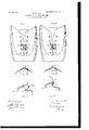
- Figure l is a plan view showing a portion of an upper with one form of my fastener applied thereto with its parts in the closed position.
- Fig. 2 is a section on the line 00 a; in Fig. 1; and
- Fig. 3 is a similar section through the fastener, detached, with its parts partly opened or separated.
- Figs. 4, 5, and 6 are similar views to Figs. 1, 2, and 3, respectively, illustrating a modified form of my fastener.
- my fastener as therein illustrated comprises two similar eyelet-engaging members which are preferably made of wire, each member consisting of a longitudinal portion 2 and end portions 3, extending laterally therefrom in the same plane, the ends of said latter portions 3 being bent to form eyelet-engaging devices of any suitable construction.
- the eyelet-engaging means herein shown consist of hooks 4:, having extended free ends 5, substantially as described in other United States Letters Pat ent Nos. 688,297 and 7 04,451, granted to me on the 10th day of December, 1901, and on the 8th day of July, 1902, respectively.
- the portion 2 of one of the eyelet-engaging members is hinged to one end of a metal strip 6, preferably by Wrapping the end of said strip around said portion 2, as shown at 7 and between its ends this member 6, which I term the connecting member, is hinged to the portion 2 of the other eyelet-engaging member by means of a hinge-leaf 8, which is made of stiff spring metal and is pivotally connected at its ends to said portion 2 and to the member 6, as best shown in Figs. 1 and 3.
- the hinge-leaf 8 near that end which is connected to one of the portions 2 is arched upward or away from the member 6 and is connected to the latter member at such a point that when said member 6 is turned into the position shown in Figs.
- the fastener shown in Figs. 4, 5, and 6 also comprises two eyelet engaging members which may be formed substantially like the eyelet engaging members above described and provided with the same eyelet-engaging hooks and free ends.
- the portions 3 of one of these members are, however, made somewhat longer than the corresponding portions of the fastener shown in Figs. 1, 2, and 3, and the longitudinal portion 2, which connects the portions 3, is made enough shorter than the longitudinal portion of the other member to pass between the end portions of the latter, said end portions 3 being bent inward and upward near the ends of the portion 2, as shown in Figs. 5 and 6.
- the connecting member 6 in this case is hinged at one end to said longitudinal portion 2, as shown at 7, and is also hinged between its ends directly to the longitudinal portion of the other eyelet-engaging member without the interposition of a hinge-leaf such as is employed in the fastener shown in Figs. 1, 2, and 3.
- the hinge connection in this case may conveniently be made by slitting the member 6 lengthwise from one end for a portion of its length and bending the ends of the strips thus formed around said longitudinal portion, as best shown in Figs. 4 and 6.
- the member 6 is also bent near its hinged end in such manner as to throw the portion 2 somewhat above the corresponding portion of the other eyelet-engaging member when the fastener is closed, as shown in Fig.
- the fastener After the fastener has been attached it is opened and closed in an obvious manner by moving the connecting member to the left in the former case and to When it is open, a last or other implement may be inserted into or withdrawn from the shoe without detaching the fastener from the eyelets on either side of the upper, and when it is closed the parts of the fastener arch over the outwardlycurved front edge of the last and conform automatically to the slope of the same, as will be readily understood.
- a detachable shoe-fastener comprising two members each having hooked fingers adapted to engage the eyelets of a shoe, and a connecting member hinged at one end to one of said first-named members and between its ends to the other member, said connecting member being formed to provide means for retaining the parts of the fastener in their closed position.
- a detachable shoe-fastener comprising two members each composed of a longitudinal portion and laterally-extending portions provided with hooked fingers adapted to engage the eyelets of a shoe, in combination with a connecting member hinged at one end to one of said longitudinal portions and between its ends to the other longitudinal portion, substantially as described.
- a shoe-fastening device comprising two members, each having hooked fingers adapted to detachably engage the eyelets of a shoe and means connecting said members and constructed to positively draw them toward each other and retain them in their closed position, and to positively separate said members.
- a shoe-fastener comprising two members, each having hooked fingers adapted to engage the eyelets of a shoe, and'a locking member having pivotal connection with each of said members.
- a shoe-fastener comprising two members, each having hooked fingers adapted to engage the eyelets of a shoe, and a locking member pivoted at its end to one of the members and intermediate its ends to the other member.
- a shoe-fastening device comprising two members having hook-shaped arms adapted to engage the eyelets of a shoe, and a locking-lever having such a pivotal connection with each of said members that when the members are closed they are automatically locked.
- a shoe-fastening device comprising two members each having hooked fingers adapted to engage the eyelets of a shoe, and an intermediate member having pivotal connection with each of said first-named members, said intermediate member being constructed to be manually operated and operating to positively draw said first-named members toward each other or to positively separate said members according to the direction in which the intermediate member is moved.
Landscapes
- Footwear And Its Accessory, Manufacturing Method And Apparatuses (AREA)
Description
No. 808,028. PATENTED DEC. 19, 1905. W. B. ELLIS.
FASTENER. FOR SHOE UPPERS.
APPLICATION FILED D130. 10, 1902 //\/l//\/TOH Wamw, a 8.9.MM,
WT/V/JSSES fflw.
UNITED sTATEs PATENT OFFICE.
TVARREN EUGENE ELLIS, OF HAVERHILL, MASSACHUSETTS, ASSIGNOR TO ELLIS LAOER COMPANY, A CORPORATION OF MAINE.
FASTENER FOR SHOE-UPPERS.
Specification of Letters Patent.
Patented Dec. 19, 1905.
Application filed December 10, 1902. Serial No. 134,600.
To all whom it may concern.-
Beitknown thatI, WARREN EUGENE ELLIs, a citizen of the United States, and a resident of Haverhill, in the county of Essex and State of Massachusetts, have invented new and useful Improvements in Fasteners for Shoe-Uppers, of which the following is a specification.
My invention relates to fasteners for temporarily securing together the eyeleted edges of the uppers of lace-shoes while being lasted, and is intended to provide a fastener having eyelet-engaging members which may be separated or drawn together and locked in the latter position without disengaging either of sald members from the eyelets of the upper in order that the device may be capable of use with a solid last and may be allowed to remain in a shoe, if desired, throughout all the operations subsequent to lasting, whether the last is in the shoe or not, so that it will be avail-' able to fasten the shoe during the process of relasting without having to be inserted again at that stage. To this end I have devised a fastener comprising two eyelet engaging members and an intermediate or connecting member, the latter being hinged at one end to one of the eyelet-engaging members and between its ends to the other eyelet-engaging member and being arranged to act as a lever for opening and closing the eyelet-engaging members. The parts are also constructed and arranged in such manner that said eyelet-engaging members when closed will not be pulled apart by the tension imposed upon the upper during the lasting and other processes.
My invention is illustrated in the accompanying drawings, in which Figure l is a plan view showing a portion of an upper with one form of my fastener applied thereto with its parts in the closed position. Fig. 2 is a section on the line 00 a; in Fig. 1; and Fig. 3 is a similar section through the fastener, detached, with its parts partly opened or separated. Figs. 4, 5, and 6 are similar views to Figs. 1, 2, and 3, respectively, illustrating a modified form of my fastener.
Each of the fasteners shown in the drawings is designed to secure two pairs of eyelets simultaneously; but the principle of my invention is independent of the number of pairs of eyelets secured.
Referring to Figs. 1, 2, and 3, my fastener as therein illustrated comprises two similar eyelet-engaging members which are preferably made of wire, each member consisting of a longitudinal portion 2 and end portions 3, extending laterally therefrom in the same plane, the ends of said latter portions 3 being bent to form eyelet-engaging devices of any suitable construction. The eyelet-engaging means herein shown consist of hooks 4:, having extended free ends 5, substantially as described in other United States Letters Pat ent Nos. 688,297 and 7 04,451, granted to me on the 10th day of December, 1901, and on the 8th day of July, 1902, respectively. The portion 2 of one of the eyelet-engaging members is hinged to one end of a metal strip 6, preferably by Wrapping the end of said strip around said portion 2, as shown at 7 and between its ends this member 6, which I term the connecting member, is hinged to the portion 2 of the other eyelet-engaging member by means of a hinge-leaf 8, which is made of stiff spring metal and is pivotally connected at its ends to said portion 2 and to the member 6, as best shown in Figs. 1 and 3. The hinge-leaf 8 near that end which is connected to one of the portions 2 is arched upward or away from the member 6 and is connected to the latter member at such a point that when said member 6 is turned into the position shown in Figs. 1 and 2 its end which is connected to the other portion 2 will engage the hinge-leaf 8 at the point 9, Fig. 3, and after pressing the latter slightly to the left against its spring action will slip past the point 9 into the space provided by the arched portion above described, in which position it will be held by the spring action of said leaf 8. This is the closed position of the fastener, in which the edges of the eyelet are drawn together as far as possible, and it will be evident that when the fastener is closed the tension imposed upon it by the process of lasting will be substantially in the direction of the line joining the pivotal connections of the member 6, and hence the force tending to draw the hinged end of said member 6 downward past the adjacent end of the leaf 8, and thus open the fastener, will be slight and may be overcome by giving said leaf 8 suflicient stiffness.
The fastener shown in Figs. 4, 5, and 6 also comprises two eyelet engaging members which may be formed substantially like the eyelet engaging members above described and provided with the same eyelet-engaging hooks and free ends. The portions 3 of one of these members are, however, made somewhat longer than the corresponding portions of the fastener shown in Figs. 1, 2, and 3, and the longitudinal portion 2, which connects the portions 3, is made enough shorter than the longitudinal portion of the other member to pass between the end portions of the latter, said end portions 3 being bent inward and upward near the ends of the portion 2, as shown in Figs. 5 and 6. The connecting member 6 in this case is hinged at one end to said longitudinal portion 2, as shown at 7, and is also hinged between its ends directly to the longitudinal portion of the other eyelet-engaging member without the interposition of a hinge-leaf such as is employed in the fastener shown in Figs. 1, 2, and 3. The hinge connection in this case may conveniently be made by slitting the member 6 lengthwise from one end for a portion of its length and bending the ends of the strips thus formed around said longitudinal portion, as best shown in Figs. 4 and 6. The member 6 is also bent near its hinged end in such manner as to throw the portion 2 somewhat above the corresponding portion of the other eyelet-engaging member when the fastener is closed, as shown in Fig. 5, so that a line joining the longitudinal portions of the eyelet-engaging members will have such a direction that the tension imposed upon the fastener by the lasting process will tend to turn the member 6' in the direction in which it turns when closing the fastener rather than in the opposite direction, with the result that said tension will not tend to open the fastener, but will hold it closed all the more tightly.
. the rightin the latter case.
Each of the forms of my fastener herein shown and described is attached to an upper in the manner clearly described in the Letters Patent above referred to by inserting its free ends through two pairs of opposite eyelets from the outside of the upper, said eyelets being engaged by the hooks 4: or 4 when the upper is under tension and being kept by the portions 5 from accidental displacement from said hooks during the handling of the upper preparatory to lasting. After the fastener has been attached it is opened and closed in an obvious manner by moving the connecting member to the left in the former case and to When it is open, a last or other implement may be inserted into or withdrawn from the shoe without detaching the fastener from the eyelets on either side of the upper, and when it is closed the parts of the fastener arch over the outwardlycurved front edge of the last and conform automatically to the slope of the same, as will be readily understood.
I claim as my invention 1. A detachable shoe-fastener comprising two members each having hooked fingers adapted to engage the eyelets of a shoe, and a connecting member hinged at one end to one of said first-named members and between its ends to the other member, said connecting member being formed to provide means for retaining the parts of the fastener in their closed position.
2. A detachable shoe-fastener comprising two members each composed of a longitudinal portion and laterally-extending portions provided with hooked fingers adapted to engage the eyelets of a shoe, in combination with a connecting member hinged at one end to one of said longitudinal portions and between its ends to the other longitudinal portion, substantially as described.
3. A shoe-fastening device comprising two members, each having hooked fingers adapted to detachably engage the eyelets of a shoe and means connecting said members and constructed to positively draw them toward each other and retain them in their closed position, and to positively separate said members.
1. A shoe-fastener comprising two members, each having hooked fingers adapted to engage the eyelets of a shoe, and'a locking member having pivotal connection with each of said members.
5. A shoe-fastener comprising two members, each having hooked fingers adapted to engage the eyelets of a shoe, and a locking member pivoted at its end to one of the members and intermediate its ends to the other member.
6. A shoe-fastening device comprising two members having hook-shaped arms adapted to engage the eyelets of a shoe, and a locking-lever having such a pivotal connection with each of said members that when the members are closed they are automatically locked.
7 A shoe-fastening device comprising two members each having hooked fingers adapted to engage the eyelets of a shoe, and an intermediate member having pivotal connection with each of said first-named members, said intermediate member being constructed to be manually operated and operating to positively draw said first-named members toward each other or to positively separate said members according to the direction in which the intermediate member is moved.
In testimony whereof I have hereunto subscribed my name this 8th day of December,
WARREN EUGENE ELLIS. Witnesses:
E. D. CHADwIcK, J OSEPH T. BRENNAN.
IIO
Priority Applications (1)
| Application Number | Priority Date | Filing Date | Title |
|---|---|---|---|
| US13460002A US808028A (en) | 1902-12-10 | 1902-12-10 | Fastener for shoe-uppers. |
Applications Claiming Priority (1)
| Application Number | Priority Date | Filing Date | Title |
|---|---|---|---|
| US13460002A US808028A (en) | 1902-12-10 | 1902-12-10 | Fastener for shoe-uppers. |
Publications (1)
| Publication Number | Publication Date |
|---|---|
| US808028A true US808028A (en) | 1905-12-19 |
Family
ID=2876510
Family Applications (1)
| Application Number | Title | Priority Date | Filing Date |
|---|---|---|---|
| US13460002A Expired - Lifetime US808028A (en) | 1902-12-10 | 1902-12-10 | Fastener for shoe-uppers. |
Country Status (1)
| Country | Link |
|---|---|
| US (1) | US808028A (en) |
Cited By (8)
| Publication number | Priority date | Publication date | Assignee | Title |
|---|---|---|---|---|
| US2787038A (en) * | 1953-05-13 | 1957-04-02 | Rupert F Jackson | Shoe fastening attachment |
| US3287774A (en) * | 1964-11-16 | 1966-11-29 | Market Forge Company | Ski boot fastening comprising step adjusted toggle means |
| US3808645A (en) * | 1972-09-11 | 1974-05-07 | Y Chow | Fastening device |
| US4157622A (en) * | 1977-09-26 | 1979-06-12 | Carlyle Lance J | Fastener for footwear |
| US4907352A (en) * | 1988-02-02 | 1990-03-13 | Jay Ginsberg | Shoe lace replacing and shoe fastening device |
| US5353483A (en) * | 1993-07-06 | 1994-10-11 | Louviere Donald L | Method and apparatus for quickly securing a laced shoe |
| US20130318827A1 (en) * | 2012-05-31 | 2013-12-05 | Ryan Ringholz | Interchangeable Strap Closure System For Footwear |
| US20170202314A1 (en) * | 2016-01-15 | 2017-07-20 | Gyuwon Song | Universal Shoe Fastener System |
-
1902
- 1902-12-10 US US13460002A patent/US808028A/en not_active Expired - Lifetime
Cited By (11)
| Publication number | Priority date | Publication date | Assignee | Title |
|---|---|---|---|---|
| US2787038A (en) * | 1953-05-13 | 1957-04-02 | Rupert F Jackson | Shoe fastening attachment |
| US3287774A (en) * | 1964-11-16 | 1966-11-29 | Market Forge Company | Ski boot fastening comprising step adjusted toggle means |
| US3808645A (en) * | 1972-09-11 | 1974-05-07 | Y Chow | Fastening device |
| US4157622A (en) * | 1977-09-26 | 1979-06-12 | Carlyle Lance J | Fastener for footwear |
| US4907352A (en) * | 1988-02-02 | 1990-03-13 | Jay Ginsberg | Shoe lace replacing and shoe fastening device |
| WO1990003743A1 (en) * | 1988-10-12 | 1990-04-19 | Jay Ginsberg | Shoe lace replacing and shoe fastening device |
| US5353483A (en) * | 1993-07-06 | 1994-10-11 | Louviere Donald L | Method and apparatus for quickly securing a laced shoe |
| US20130318827A1 (en) * | 2012-05-31 | 2013-12-05 | Ryan Ringholz | Interchangeable Strap Closure System For Footwear |
| US10021935B2 (en) * | 2012-05-31 | 2018-07-17 | Plae, Inc. | Interchangeable strap closure system for footwear |
| US20170202314A1 (en) * | 2016-01-15 | 2017-07-20 | Gyuwon Song | Universal Shoe Fastener System |
| US11071354B2 (en) * | 2016-01-15 | 2021-07-27 | Gyuwon Song | Universal shoe fastener system |
Similar Documents
| Publication | Publication Date | Title |
|---|---|---|
| US808028A (en) | Fastener for shoe-uppers. | |
| US827987A (en) | Shoe-lacer. | |
| US1439241A (en) | Clasp | |
| US624287A (en) | Fastener for shoe-uppers | |
| US805776A (en) | Holder for the flies of boots and shoes. | |
| US990242A (en) | Means for tying shoe-uppers. | |
| US574686A (en) | Lacing-fastener for boots or shoes | |
| US704451A (en) | Fastener for shoe-uppers. | |
| US936391A (en) | Fastening device for shoe-uppers. | |
| US44286A (en) | William e | |
| US904479A (en) | Lacing-hook. | |
| US884454A (en) | Shoe-fastener. | |
| US1174164A (en) | End fastener for shoe-laces | |
| US890490A (en) | Shoe-lace fastening. | |
| US641063A (en) | Cord-holder. | |
| US55853A (en) | Improved lacing for boots and shoes | |
| US774659A (en) | Fastener for shoe-uppers. | |
| US1195131A (en) | Lacer | |
| US309981A (en) | quentell | |
| US668948A (en) | Lacing device. | |
| US652368A (en) | Holder for flies of boots or shoes. | |
| US55923A (en) | Improved lacing for boots and shoes | |
| US968359A (en) | Boot and shoe. | |
| US1132785A (en) | Clasp. | |
| US930485A (en) | Holder for the eyeleted edges of boots and shoes. |