US6394858B1 - Socket contact for electrical connectors - Google Patents
Socket contact for electrical connectors Download PDFInfo
- Publication number
- US6394858B1 US6394858B1 US09/786,776 US78677601A US6394858B1 US 6394858 B1 US6394858 B1 US 6394858B1 US 78677601 A US78677601 A US 78677601A US 6394858 B1 US6394858 B1 US 6394858B1
- Authority
- US
- United States
- Prior art keywords
- contact
- sheet
- metal frame
- contact elements
- socket contact
- Prior art date
- Legal status (The legal status is an assumption and is not a legal conclusion. Google has not performed a legal analysis and makes no representation as to the accuracy of the status listed.)
- Expired - Fee Related
Links
Images

Classifications
-
- H—ELECTRICITY
- H01—ELECTRIC ELEMENTS
- H01R—ELECTRICALLY-CONDUCTIVE CONNECTIONS; STRUCTURAL ASSOCIATIONS OF A PLURALITY OF MUTUALLY-INSULATED ELECTRICAL CONNECTING ELEMENTS; COUPLING DEVICES; CURRENT COLLECTORS
- H01R13/00—Details of coupling devices of the kinds covered by groups H01R12/70 or H01R24/00 - H01R33/00
- H01R13/02—Contact members
- H01R13/10—Sockets for co-operation with pins or blades
-
- H—ELECTRICITY
- H01—ELECTRIC ELEMENTS
- H01R—ELECTRICALLY-CONDUCTIVE CONNECTIONS; STRUCTURAL ASSOCIATIONS OF A PLURALITY OF MUTUALLY-INSULATED ELECTRICAL CONNECTING ELEMENTS; COUPLING DEVICES; CURRENT COLLECTORS
- H01R13/00—Details of coupling devices of the kinds covered by groups H01R12/70 or H01R24/00 - H01R33/00
- H01R13/02—Contact members
- H01R13/10—Sockets for co-operation with pins or blades
- H01R13/11—Resilient sockets
- H01R13/114—Resilient sockets co-operating with pins or blades having a square transverse section
-
- H—ELECTRICITY
- H01—ELECTRIC ELEMENTS
- H01R—ELECTRICALLY-CONDUCTIVE CONNECTIONS; STRUCTURAL ASSOCIATIONS OF A PLURALITY OF MUTUALLY-INSULATED ELECTRICAL CONNECTING ELEMENTS; COUPLING DEVICES; CURRENT COLLECTORS
- H01R13/00—Details of coupling devices of the kinds covered by groups H01R12/70 or H01R24/00 - H01R33/00
- H01R13/02—Contact members
- H01R13/15—Pins, blades or sockets having separate spring member for producing or increasing contact pressure
- H01R13/187—Pins, blades or sockets having separate spring member for producing or increasing contact pressure with spring member in the socket
Definitions
- the present invention concerns a socket contact for electrical connectors the socket contact having a box shaped sheet-metal frame and four contact elements incorporated therein as well as a connection part for cables, which adjoins the sheet-metal frame, and in which the sheet-metal frame has a front frame part and a rear frame part.
- a socket contact is known, for example from EP-A-255 245.
- Socket contacts are used in particular in signal transmission for control devices with a high number of poles, such as for example motor control devices. Since a large number of connector pins are provided in a plug-in connector, a compact design of these connector sockets is very important.
- the reinforcing cages of the connector sockets typically have transverse dimensions of 2 ⁇ 2 mm.
- EP-225 245 A1 describes a socket contact of the type specified in the precharacterizing clause of claim 1.
- the insertion region is designed as a box-shaped sheet-metal frame with four contact tongues, which are fastened on both sides to frame parts and have contact points formed in the vicinity of the insertion region.
- the contact points are staggered by pairs by a short distance and the tongues are all of the same design, with the result that the entire spring force of all four resilient tongues acts within a short time interval during the insertion operation, with the result that, if up to 50 connector pins of a plug-in connector are inserted simultaneously into a corresponding connector socket, the insertion force is very high during that short time interval.
- EP-353 330 describes a socket contact for electrical connectors in which contact elements comprise resilient elements, with a free head end, the contact elements being arranged lying one behind the other in the direction of insertion. In this way, the insertion force is distributed over time and is consequently spread evenly throughout the insertion operation.
- the mutually opposite points of the resilient elements are not the same.
- the free end of a long resilient tongue and a contact element bent inwards from a short cutout respectively lie opposite one another.
- a relatively rigid guidance of the connector to be inserted consequently takes place at these relatively inflexible protrusions, with the result that a jammed insertion is of the connector pins is avoided.
- the spring deflection of the resilient tongues is limited by little space being provided for free movement within the reinforcing cage.
- EP-A-727 843 discloses an asymmetric electrical receptacle terminal having a box-shaped sheet-frame and contact arms separated from the frame by a certain gap to allow outward biasing thereof.
- the present invention is based on the object of improving a socket contact of the type mentioned at the beginning in such a way that optimum electrical contacting and high retaining forces are realized with low insertion forces distributed throughout the entire insertion operation.
- the “box” is in two parts, with respectively two sides joined together via an edge forming a unit. That is to say, resilient elements whose spring deflections form an angle of 90° with respect to one another are fastened on one part of the “frame” and the same arrangement is to be found diametrically opposite. Consequently, the flexibility of the contact elements is not limited only to their own spring deflection, but instead the box frame can partially covibrate in the reinforcing cage. As a result an insertion force is accomplished, which is distributed more evenly throughout the insertion operation than in the case of the prior art.
- FIGS. 1 a and b show two perspective views of the socket contact according to the invention with the reinforcing cage pulled off, and
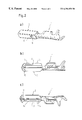
- FIG. 2 shows three perspective views of the socket contact according to the invention with the reinforcing cage fitted.
- FIG. 1 a perspectively shows on the right the socket contact 1 and on the left the reinforcing cage 2 , which is fitted over the box-shaped sheet-metal frame 3 of the socket contact, in order to reinforce the latter.
- the box-shaped sheet-metal frame 3 has four contact elements 5 , 6 , first contact elements 5 connecting a front frame part 7 to a rear frame part 8 .
- Second contact elements 6 extend from the front frame part 7 and have a free head end 9 , which extends in the direction of the rear frame part 8 .
- the front frame part 7 is in two parts, with two sides respectively joined together via an edge and the other side ends not being joined together.
- two neighboring contact elements 5 and 6 respectively are fastened on a front frame part and the two frame parts lie diametrically opposite one another.
- the arrangement of the contact elements is symmetrical to the extent that the first contact elements 5 and the second contact elements 6 likewise lie opposite one another.
- the first contact elements are bent sharply inwards just behind the front frame part, in order to form a resting point there with the connector pin to be inserted, whereas in the case of the second contact elements, the contact with the connector does not take place until later during the insertion operation, via the head ends of the second contact elements.
- the reinforcing cage 2 is slipped over the sheet-metal frame 3 and fastened by means of brackets 10 to the sheet-metal frame 3 in a recess 11 provided for this purpose.
- FIG. 2 shows the socket contact 1 provided with the reinforcing cage 2 in several perspective views.
- FIG. 2 a shows the fastening brackets 10
- FIG. 2 b clearly shows that the reinforcing cage has, on its front end, inwardly curved sheet-metal lugs 12 , which guide the connector pin.
- the reinforcing cage 2 is produced from stainless steel, whereas the rest of the sheet-metal frame is produced from a copper wrought alloy.
- the reinforcing cage 2 has on its upper side a rib 13 , which serves for coding during insertion into a connector housing.
- FIG. 2 c shows that on this coding rib 13 fastening lugs 14 are provided, by which the reinforcing cage 2 folded from a metal sheet is fastened in itself.
- the reinforcing cage is, furthermore, dimensioned in such a way that the sides of the front parts 7 of the sheet metal frame, on which the second contact elements are provided, cannot move outwards, whereas the first contact elements 5 together with the corresponding sides to which they are joined on the front sheet-metal frame part 7 can move somewhat in the reinforcing cage 2 .
- This provides the overall socket arrangement with some flexibility, which leads to evening out of the insertion force to be expended.
Landscapes
- Details Of Connecting Devices For Male And Female Coupling (AREA)
- Coupling Device And Connection With Printed Circuit (AREA)
Abstract
The present invention concerns a socket contact (1) for electrical connectors, having a box-shaped sheet-metal frame (3) and four contact elements (5, 6) incorporated therein as well as a connection part for cables, which adjoins the sheet-metal frame. In this case, the sheet-metal frame has, seen in the direction of insertion, a front frame part (7). The latter comprises two parts which have two sides respectively joined together via an edge, of which sides those lying respectively opposite one another are either joined via a first contact element (5) to the rear frame part (8) or respectively have a second contact element (6) with a free head end (9), which extends in the direction of the rear frame part.
Description
This application claims the benefit of the earlier filed International Application No. PCT/EP99/06532, International Filing Date, Sept. 6, 1999, which designated the United States of America, and which international application was published under PCT Article 21(2) in English on Mar. 16, 2000 as WO Publication No. WO 00/14828.
1. Field of the Invention
The present invention concerns a socket contact for electrical connectors the socket contact having a box shaped sheet-metal frame and four contact elements incorporated therein as well as a connection part for cables, which adjoins the sheet-metal frame, and in which the sheet-metal frame has a front frame part and a rear frame part. Such a socket contact is known, for example from EP-A-255 245.
Socket contacts are used in particular in signal transmission for control devices with a high number of poles, such as for example motor control devices. Since a large number of connector pins are provided in a plug-in connector, a compact design of these connector sockets is very important. The reinforcing cages of the connector sockets typically have transverse dimensions of 2×2 mm.
Since a plugging operation involves inserting a large number of connectors into corresponding sockets, the inserting force to be expended must mot be too great and at the same time satisfactory electrical contact and adequately high retaining forces must be ensured.
2. Description of the Prior Art
EP-225 245 A1 describes a socket contact of the type specified in the precharacterizing clause of claim 1. In this case, the insertion region is designed as a box-shaped sheet-metal frame with four contact tongues, which are fastened on both sides to frame parts and have contact points formed in the vicinity of the insertion region. The contact points are staggered by pairs by a short distance and the tongues are all of the same design, with the result that the entire spring force of all four resilient tongues acts within a short time interval during the insertion operation, with the result that, if up to 50 connector pins of a plug-in connector are inserted simultaneously into a corresponding connector socket, the insertion force is very high during that short time interval.
EP-353 330 describes a socket contact for electrical connectors in which contact elements comprise resilient elements, with a free head end, the contact elements being arranged lying one behind the other in the direction of insertion. In this way, the insertion force is distributed over time and is consequently spread evenly throughout the insertion operation. The mutually opposite points of the resilient elements are not the same. The free end of a long resilient tongue and a contact element bent inwards from a short cutout respectively lie opposite one another. A relatively rigid guidance of the connector to be inserted consequently takes place at these relatively inflexible protrusions, with the result that a jammed insertion is of the connector pins is avoided. Furthermore, the spring deflection of the resilient tongues is limited by little space being provided for free movement within the reinforcing cage.
EP-A-727 843 discloses an asymmetric electrical receptacle terminal having a box-shaped sheet-frame and contact arms separated from the frame by a certain gap to allow outward biasing thereof.
The present invention is based on the object of improving a socket contact of the type mentioned at the beginning in such a way that optimum electrical contacting and high retaining forces are realized with low insertion forces distributed throughout the entire insertion operation.
This object is achieved as claimed. Preferred embodiments of the invention are characterized in the subclaims.
According to the invention, at the insertion end of the box-shaped socket Connector, the “box” is in two parts, with respectively two sides joined together via an edge forming a unit. That is to say, resilient elements whose spring deflections form an angle of 90° with respect to one another are fastened on one part of the “frame” and the same arrangement is to be found diametrically opposite. Consequently, the flexibility of the contact elements is not limited only to their own spring deflection, but instead the box frame can partially covibrate in the reinforcing cage. As a result an insertion force is accomplished, which is distributed more evenly throughout the insertion operation than in the case of the prior art.
The invention is explained in more detail below on the basis of the description of an exemplary embodiment with reference to the drawings, in which:
FIGS. 1a and b show two perspective views of the socket contact according to the invention with the reinforcing cage pulled off, and
FIG. 2 shows three perspective views of the socket contact according to the invention with the reinforcing cage fitted.
FIG. 1a perspectively shows on the right the socket contact 1 and on the left the reinforcing cage 2, which is fitted over the box-shaped sheet-metal frame 3 of the socket contact, in order to reinforce the latter. Behind the sheet-metal frame 3 there is the connection part 4 for a cable connection and for crimping the cable. The box-shaped sheet-metal frame 3 has four contact elements 5, 6, first contact elements 5 connecting a front frame part 7 to a rear frame part 8. Second contact elements 6 extend from the front frame part 7 and have a free head end 9, which extends in the direction of the rear frame part 8.
The front frame part 7 is in two parts, with two sides respectively joined together via an edge and the other side ends not being joined together. As a result, two neighboring contact elements 5 and 6 respectively are fastened on a front frame part and the two frame parts lie diametrically opposite one another. Furthermore the arrangement of the contact elements is symmetrical to the extent that the first contact elements 5 and the second contact elements 6 likewise lie opposite one another.
The first contact elements are bent sharply inwards just behind the front frame part, in order to form a resting point there with the connector pin to be inserted, whereas in the case of the second contact elements, the contact with the connector does not take place until later during the insertion operation, via the head ends of the second contact elements. The reinforcing cage 2 is slipped over the sheet-metal frame 3 and fastened by means of brackets 10 to the sheet-metal frame 3 in a recess 11 provided for this purpose.
FIG. 2 shows the socket contact 1 provided with the reinforcing cage 2 in several perspective views. FIG. 2a shows the fastening brackets 10 and FIG. 2b clearly shows that the reinforcing cage has, on its front end, inwardly curved sheet-metal lugs 12, which guide the connector pin. The reinforcing cage 2 is produced from stainless steel, whereas the rest of the sheet-metal frame is produced from a copper wrought alloy. As can be seen in FIG. 2b, the reinforcing cage 2 has on its upper side a rib 13, which serves for coding during insertion into a connector housing. FIG. 2c shows that on this coding rib 13 fastening lugs 14 are provided, by which the reinforcing cage 2 folded from a metal sheet is fastened in itself.
The reinforcing cage is, furthermore, dimensioned in such a way that the sides of the front parts 7 of the sheet metal frame, on which the second contact elements are provided, cannot move outwards, whereas the first contact elements 5 together with the corresponding sides to which they are joined on the front sheet-metal frame part 7 can move somewhat in the reinforcing cage 2. This provides the overall socket arrangement with some flexibility, which leads to evening out of the insertion force to be expended.
The exemplary embodiment described above is not to be understood in a restrictive sense. The invention relates to all socket contacts covered by the wording of the claims.
Claims (12)
1. A socket contact for electrical connectors, having a box shaped sheet metal frame and four contact elements incorporated therein, the socket contact having a connection part for cables which is linked to the sheet metal frame wherein the sheet metal frame includes on a side opposite to the connection part for the cables a front frame part comprising two sub-parts, each of the sub-parts having respectively, two sides joined together by an edge, wherein a first set of sides lying respectively, opposite one another are joined by a first of the contact elements to the rear frame part, and wherein a second set of sides lying respectively, opposite one another includes a second of the contact elements which include a free head end extending in the direction of the rear frame part.
2. A socket contact according to claim 1 , wherein said first contact elements are bent near said front frame part in a relatively sharply curved manner towards the interior of said sheet-metal frame and said second contact elements have, in the region of said free end, an inwardly bent contact region.
3. A socket contact according to claim 1 , wherein said sheet-metal frame consists of a copper wrought alloy and is spot-welded on one edge of its rear region.
4. A socket contact according to claim 1 , wherein said first contact elements produce a higher surface pressure that said second contact elements.
5. A socket contact according to claim 1 further including a reinforcing cage adapted to be fitted over said sheet-metal frame and not allowing any play for an outwardly directed movement of said sides of said front part of said frame, on which said second contact elements are arranged with a free end, whereas said sides which are jointed to said rear frame part via said first contact elements can move outwardly in the reinforcing cage.
6. A socket contact according to claim 5 , wherein in the vicinity of said sheet-metal frame there is arranged said reinforcing cage of steel, which is fastened in said rear frame part of said sheet-metal frame to the latter, said first contact element and said second contact element respectively having first and second contact regions which are spaced apart from one another in a direction of insertion.
7. A socket contact according to claim 5 , wherein said reinforcing cage has at an insertion end partially inwardly bent lugs for guiding the connector pin to be inserted.
8. A socket contact according to claim 5 , wherein on a part lying above the rear part of said sheet metal frame, the reinforcing cage having brackets folded inwardly into a corresponding recess in said sheet-metal frame.
9. A socket contact according to claim 5 , wherein said reinforcing cage has a coding rib.
10. A socket contact according to claim 5 , wherein said first contact elements are bent near said front frame part in a relatively sharply curved manner towards the interior of said sheet-metal frame and said second contact elements have, in the region of said free end, an inwardly bent contact region.
11. A socket contact according to claim 5 , wherein said sheet-metal frame consists of a copper wrought alloy and is spot-welded on one edge of its rear region.
12. A socket contact according to claim 5 , wherein said first contact elements produce a higher surface pressure that said second contact elements.
Applications Claiming Priority (3)
| Application Number | Priority Date | Filing Date | Title |
|---|---|---|---|
| DE19841232A DE19841232C2 (en) | 1998-09-09 | 1998-09-09 | Socket contact for electrical plugs |
| DE19841232 | 1998-09-09 | ||
| PCT/EP1999/006532 WO2000014828A1 (en) | 1998-09-09 | 1999-09-06 | Socket contact for electrical connectors |
Publications (1)
| Publication Number | Publication Date |
|---|---|
| US6394858B1 true US6394858B1 (en) | 2002-05-28 |
Family
ID=7880392
Family Applications (1)
| Application Number | Title | Priority Date | Filing Date |
|---|---|---|---|
| US09/786,776 Expired - Fee Related US6394858B1 (en) | 1998-09-09 | 1999-09-06 | Socket contact for electrical connectors |
Country Status (9)
| Country | Link |
|---|---|
| US (1) | US6394858B1 (en) |
| EP (1) | EP1112608A1 (en) |
| JP (1) | JP2002524834A (en) |
| KR (1) | KR100704279B1 (en) |
| BR (1) | BR9913871A (en) |
| CA (1) | CA2343248A1 (en) |
| DE (1) | DE19841232C2 (en) |
| HU (1) | HUP0103753A2 (en) |
| WO (1) | WO2000014828A1 (en) |
Cited By (43)
| Publication number | Priority date | Publication date | Assignee | Title |
|---|---|---|---|---|
| US20040242085A1 (en) * | 2003-04-15 | 2004-12-02 | Guy Coulon | Contacting part for electrical connector |
| US20050059303A1 (en) * | 2003-08-27 | 2005-03-17 | Panella Augusto P. | Dual plane power contact |
| US6872103B1 (en) * | 1998-08-03 | 2005-03-29 | Tyco Electronics Logistics Ag | Bushing contact |
| US20050118891A1 (en) * | 2003-11-28 | 2005-06-02 | J. S. T. Mfg. Co., Ltd. | Female terminal for heavy current and female terminal for heavy current with shell |
| US20070100733A1 (en) * | 2005-10-28 | 2007-05-03 | Albert-Jan Huizing | System and method for simultaneous trading of options |
| US20100197178A1 (en) * | 2007-10-11 | 2010-08-05 | Gheorghe Hotea | Vibration-Damping Contact Element |
| US20120077393A1 (en) * | 2009-05-19 | 2012-03-29 | Chul-Sub Lee | Connector For Low Profile Fuse |
| US20130078874A1 (en) * | 2011-09-28 | 2013-03-28 | Sumitomo Wiring Systems, Ltd. | Terminal fitting |
| US20130244510A1 (en) * | 2012-03-19 | 2013-09-19 | Yazaki Europe Ltd. | Electric terminal |
| US20140060924A1 (en) * | 2012-08-29 | 2014-03-06 | Hitachi Metals, Ltd. | Connector and wire harness |
| US8721376B1 (en) * | 2012-11-01 | 2014-05-13 | Avx Corporation | Single element wire to board connector |
| US20150111443A1 (en) * | 2013-10-23 | 2015-04-23 | Delphi Technologies, Inc. | Contact socket for an electrical plug connector |
| US20150244106A1 (en) * | 2014-02-25 | 2015-08-27 | Yazaki Corporation | Connection terminal |
| US9136641B2 (en) | 2012-11-01 | 2015-09-15 | Avx Corporation | Single element wire to board connector |
| US20160028169A1 (en) * | 2014-07-22 | 2016-01-28 | Lear Corporation | Electric Terminal Assembly |
| US20160087359A1 (en) * | 2014-09-22 | 2016-03-24 | Tyco Electronics (Shanghai) Co. Ltd. | Electrical Connector |
| US20160087366A1 (en) * | 2014-09-22 | 2016-03-24 | Ideal Industries, Inc. | Terminals for electrical connectors |
| US20160344129A1 (en) * | 2015-05-22 | 2016-11-24 | Yazaki Europe Ltd. | Contact for electrical connectors |
| US20160352034A1 (en) * | 2014-04-18 | 2016-12-01 | Japan Aviation Electronics Industry, Limited | Female contact and power connector |
| US9905953B1 (en) * | 2016-09-30 | 2018-02-27 | Slobodan Pavlovic | High power spring-actuated electrical connector |
| US10122108B2 (en) | 2014-04-24 | 2018-11-06 | Molex, Llc | Terminal fitting |
| US10218107B2 (en) | 2014-10-06 | 2019-02-26 | Avx Corporation | Caged poke home contact |
| US20190097344A1 (en) * | 2017-09-26 | 2019-03-28 | Cvilux Corporation | Socket connector and socket terminal thereof |
| US10320096B2 (en) | 2017-06-01 | 2019-06-11 | Avx Corporation | Flexing poke home contact |
| US10374328B2 (en) * | 2015-07-23 | 2019-08-06 | Molex, Llc | Terminal fitting with hood |
| US20200014150A1 (en) * | 2018-07-05 | 2020-01-09 | Oupiin Electronic (Kunshan) Co., Ltd. | High-speed connector assembly, socket connector and socket terminal |
| US10707598B2 (en) * | 2018-01-23 | 2020-07-07 | Tyco Electronics (Shanghai) Co. Ltd. | Conductive terminal and connector assembly |
| TWI725721B (en) * | 2020-01-22 | 2021-04-21 | 凡甲科技股份有限公司 | Contact |
| US11264754B2 (en) * | 2017-03-01 | 2022-03-01 | Molex, Llc | Electrical terminal and connector assembly |
| US20220158376A1 (en) * | 2019-03-12 | 2022-05-19 | Autonetworks Technologies, Ltd. | Terminal, connector and connector assembly |
| US20220181812A1 (en) * | 2019-04-17 | 2022-06-09 | Sumitomo Wiring Systems, Ltd. | Female terminal, connector module, communication cable with connector, and connector assembly |
| US11394153B2 (en) * | 2019-08-08 | 2022-07-19 | Molex, Llc | Connector and terminal |
| US11398696B2 (en) | 2018-06-07 | 2022-07-26 | Eaton Intelligent Power Limited | Electrical connector assembly with internal spring component |
| US11411336B2 (en) | 2018-02-26 | 2022-08-09 | Eaton Intelligent Power Limited | Spring-actuated electrical connector for high-power applications |
| US20220407258A1 (en) * | 2021-06-18 | 2022-12-22 | Lear Corporation | Electrical Terminal and Electrical Connector Assembly for Electrically Conductive Structures |
| US11721927B2 (en) | 2019-09-09 | 2023-08-08 | Royal Precision Products Llc | Connector recording system with readable and recordable indicia |
| US11721942B2 (en) | 2019-09-09 | 2023-08-08 | Eaton Intelligent Power Limited | Connector system for a component in a power management system in a motor vehicle |
| US20240055789A1 (en) * | 2020-12-22 | 2024-02-15 | Molex, Llc | Electrical terminal |
| US11929572B2 (en) | 2020-07-29 | 2024-03-12 | Eaton Intelligent Power Limited | Connector system including an interlock system |
| US11990720B2 (en) | 2019-01-21 | 2024-05-21 | Eaton Intelligent Power Limited | Power distribution assembly with boltless busbar system |
| US20240291192A1 (en) * | 2023-02-24 | 2024-08-29 | Sibas Electronics (Xiamen) Co. Ltd. | Connector Terminal and Connector |
| US12237605B2 (en) | 2019-01-15 | 2025-02-25 | Eaton Intelligent Power Limited | Shielded electrical connector system with internal spring component |
| GB2639107A (en) * | 2024-01-15 | 2025-09-10 | Sibas Electronics Xiamen Co Ltd | Connector terminal and connector |
Families Citing this family (5)
| Publication number | Priority date | Publication date | Assignee | Title |
|---|---|---|---|---|
| EP1271702B2 (en) * | 2001-06-22 | 2010-06-02 | Delphi Technologies, Inc. | Electrical receptacle contact |
| GB0115287D0 (en) * | 2001-06-22 | 2001-08-15 | Delphi Tech Inc | Female electrical terminal |
| US20030060090A1 (en) | 2001-09-21 | 2003-03-27 | Allgood Christopher L. | High current automotive electrical connector and terminal |
| DE102006006316B3 (en) * | 2006-02-11 | 2007-10-31 | Tyco Electronics Amp Gmbh | Electrical socket contact for electrical plug, has two contact levels provided in contact area, in which four contact points or contact sections are provided on four sides for electrical contacting of contacts |
| DE102006027674B3 (en) * | 2006-06-14 | 2008-01-31 | Tyco Electronics Amp Gmbh | Electrical bushing contact, has two contact points, which are provided at upper contact element, at spring-shackles contact element, and at lower contact element |
Citations (12)
| Publication number | Priority date | Publication date | Assignee | Title |
|---|---|---|---|---|
| US4076369A (en) | 1976-07-26 | 1978-02-28 | Northern Telecom Limited | Box terminal for card edge receptacles in telecommunications systems and the like |
| US4707050A (en) * | 1983-01-28 | 1987-11-17 | Grote & Hartmann Gmbh & Co. Kg | Extra locking element for round plugs |
| EP0255245A1 (en) | 1986-07-31 | 1988-02-03 | Amp Incorporated | Contact socket with improved contact force |
| EP0353330A1 (en) | 1988-08-05 | 1990-02-07 | Weidmüller Interface GmbH & Co. | Socket contact |
| US4934965A (en) * | 1988-05-26 | 1990-06-19 | Kabelwerke Reinshagen Gmbh | Electrical connector with a spring cage receptacle |
| US5342226A (en) | 1993-06-21 | 1994-08-30 | Electro-Wire Products, Inc. | Female blade terminal |
| EP0652605A1 (en) | 1993-11-04 | 1995-05-10 | Sumitomo Wiring Systems, Ltd. | Female terminal fitting for connector |
| EP0727843A2 (en) | 1995-02-17 | 1996-08-21 | The Whitaker Corporation | Asymmetric electrical receptacle terminal |
| EP0767514A1 (en) | 1995-10-05 | 1997-04-09 | Itt Manufacturing Enterprises, Inc. | One-piece hooded socket contact and method of producing same |
| WO1998016972A1 (en) | 1996-10-15 | 1998-04-23 | United Technologies Automotive, Inc. | Electrical terminal |
| US5951338A (en) * | 1996-10-21 | 1999-09-14 | Sumitomo Wiring Systems, Ltd. | Cover of terminal fitting |
| US6186840B1 (en) * | 1998-09-09 | 2001-02-13 | Framatome Connectors International | Female connector for electrical connectors having a coding rib |
-
1998
- 1998-09-09 DE DE19841232A patent/DE19841232C2/en not_active Expired - Fee Related
-
1999
- 1999-09-06 BR BR9913871-9A patent/BR9913871A/en not_active IP Right Cessation
- 1999-09-06 EP EP99946128A patent/EP1112608A1/en not_active Withdrawn
- 1999-09-06 WO PCT/EP1999/006532 patent/WO2000014828A1/en not_active Ceased
- 1999-09-06 KR KR1020017002970A patent/KR100704279B1/en not_active Expired - Fee Related
- 1999-09-06 HU HU0103753A patent/HUP0103753A2/en unknown
- 1999-09-06 JP JP2000569468A patent/JP2002524834A/en active Pending
- 1999-09-06 CA CA002343248A patent/CA2343248A1/en not_active Abandoned
- 1999-09-06 US US09/786,776 patent/US6394858B1/en not_active Expired - Fee Related
Patent Citations (12)
| Publication number | Priority date | Publication date | Assignee | Title |
|---|---|---|---|---|
| US4076369A (en) | 1976-07-26 | 1978-02-28 | Northern Telecom Limited | Box terminal for card edge receptacles in telecommunications systems and the like |
| US4707050A (en) * | 1983-01-28 | 1987-11-17 | Grote & Hartmann Gmbh & Co. Kg | Extra locking element for round plugs |
| EP0255245A1 (en) | 1986-07-31 | 1988-02-03 | Amp Incorporated | Contact socket with improved contact force |
| US4934965A (en) * | 1988-05-26 | 1990-06-19 | Kabelwerke Reinshagen Gmbh | Electrical connector with a spring cage receptacle |
| EP0353330A1 (en) | 1988-08-05 | 1990-02-07 | Weidmüller Interface GmbH & Co. | Socket contact |
| US5342226A (en) | 1993-06-21 | 1994-08-30 | Electro-Wire Products, Inc. | Female blade terminal |
| EP0652605A1 (en) | 1993-11-04 | 1995-05-10 | Sumitomo Wiring Systems, Ltd. | Female terminal fitting for connector |
| EP0727843A2 (en) | 1995-02-17 | 1996-08-21 | The Whitaker Corporation | Asymmetric electrical receptacle terminal |
| EP0767514A1 (en) | 1995-10-05 | 1997-04-09 | Itt Manufacturing Enterprises, Inc. | One-piece hooded socket contact and method of producing same |
| WO1998016972A1 (en) | 1996-10-15 | 1998-04-23 | United Technologies Automotive, Inc. | Electrical terminal |
| US5951338A (en) * | 1996-10-21 | 1999-09-14 | Sumitomo Wiring Systems, Ltd. | Cover of terminal fitting |
| US6186840B1 (en) * | 1998-09-09 | 2001-02-13 | Framatome Connectors International | Female connector for electrical connectors having a coding rib |
Cited By (83)
| Publication number | Priority date | Publication date | Assignee | Title |
|---|---|---|---|---|
| US6872103B1 (en) * | 1998-08-03 | 2005-03-29 | Tyco Electronics Logistics Ag | Bushing contact |
| US20040242085A1 (en) * | 2003-04-15 | 2004-12-02 | Guy Coulon | Contacting part for electrical connector |
| US6994600B2 (en) * | 2003-04-15 | 2006-02-07 | Guy Coulon | Contacting part for electrical connector |
| US20050059303A1 (en) * | 2003-08-27 | 2005-03-17 | Panella Augusto P. | Dual plane power contact |
| US20050118891A1 (en) * | 2003-11-28 | 2005-06-02 | J. S. T. Mfg. Co., Ltd. | Female terminal for heavy current and female terminal for heavy current with shell |
| US7048597B2 (en) * | 2003-11-28 | 2006-05-23 | J.S.T. Mfg. Co., Ltd. | Female terminal for heavy current and female terminal for heavy current with shell |
| US20070100733A1 (en) * | 2005-10-28 | 2007-05-03 | Albert-Jan Huizing | System and method for simultaneous trading of options |
| US7698187B2 (en) * | 2005-10-28 | 2010-04-13 | Liffe Administration And Management | System and method for simultaneous trading of options |
| US20100197178A1 (en) * | 2007-10-11 | 2010-08-05 | Gheorghe Hotea | Vibration-Damping Contact Element |
| US7988505B2 (en) * | 2007-10-11 | 2011-08-02 | Tyco Electronics Amp Gmbh | Vibration-damping contact element |
| US20120077393A1 (en) * | 2009-05-19 | 2012-03-29 | Chul-Sub Lee | Connector For Low Profile Fuse |
| US8668532B2 (en) * | 2009-05-19 | 2014-03-11 | Tyco Electronics Amp Korea Ltd. | Connector for low profile fuse |
| US20130078874A1 (en) * | 2011-09-28 | 2013-03-28 | Sumitomo Wiring Systems, Ltd. | Terminal fitting |
| US8795007B2 (en) * | 2011-09-28 | 2014-08-05 | Sumitomo Wiring Systems, Ltd. | Terminal fitting |
| US20130244510A1 (en) * | 2012-03-19 | 2013-09-19 | Yazaki Europe Ltd. | Electric terminal |
| US8858274B2 (en) * | 2012-03-19 | 2014-10-14 | Yazaki Europe Ltd. | Electric terminal |
| US9153901B2 (en) * | 2012-08-29 | 2015-10-06 | Hitachi Metals, Ltd. | Connector and wire harness |
| US20140060924A1 (en) * | 2012-08-29 | 2014-03-06 | Hitachi Metals, Ltd. | Connector and wire harness |
| US8721376B1 (en) * | 2012-11-01 | 2014-05-13 | Avx Corporation | Single element wire to board connector |
| US9768527B2 (en) | 2012-11-01 | 2017-09-19 | Avx Corporation | Single element wire to board connector |
| US10116067B2 (en) | 2012-11-01 | 2018-10-30 | Avx Corporation | Single element wire to board connector |
| US9466893B2 (en) | 2012-11-01 | 2016-10-11 | Avx Corporation | Single element wire to board connector |
| US9136641B2 (en) | 2012-11-01 | 2015-09-15 | Avx Corporation | Single element wire to board connector |
| US9166325B2 (en) | 2012-11-01 | 2015-10-20 | Avx Corporation | Single element wire to board connector |
| US20150111443A1 (en) * | 2013-10-23 | 2015-04-23 | Delphi Technologies, Inc. | Contact socket for an electrical plug connector |
| EP2866306B1 (en) * | 2013-10-23 | 2020-07-29 | Aptiv Technologies Limited | Contact socket for an electric plug |
| US9455516B2 (en) * | 2013-10-23 | 2016-09-27 | Delphi Technologies, Inc. | Contact socket for an electrical plug connector |
| KR20150047102A (en) * | 2013-10-23 | 2015-05-04 | 델피 테크놀로지스 인코포레이티드 | Contact socket for an electrical plug connection |
| CN104577408A (en) * | 2013-10-23 | 2015-04-29 | 德尔菲技术公司 | Contact socket for an electrical plug connector |
| CN104577408B (en) * | 2013-10-23 | 2017-10-24 | 德尔菲技术公司 | The contact socket connected for plug |
| US20150244106A1 (en) * | 2014-02-25 | 2015-08-27 | Yazaki Corporation | Connection terminal |
| US20160352034A1 (en) * | 2014-04-18 | 2016-12-01 | Japan Aviation Electronics Industry, Limited | Female contact and power connector |
| US9716331B2 (en) * | 2014-04-18 | 2017-07-25 | Japan Aviation Electronics Industry, Limited | Female contact and power connector |
| US10381766B2 (en) | 2014-04-24 | 2019-08-13 | Molex, Llc | Terminal fitting |
| US10122108B2 (en) | 2014-04-24 | 2018-11-06 | Molex, Llc | Terminal fitting |
| US20160028169A1 (en) * | 2014-07-22 | 2016-01-28 | Lear Corporation | Electric Terminal Assembly |
| US9847591B2 (en) * | 2014-07-22 | 2017-12-19 | Lear Corporation | Electric terminal assembly |
| US10014614B2 (en) | 2014-09-22 | 2018-07-03 | Ideal Industries, Inc. | Terminals for electrical connectors |
| US20160087359A1 (en) * | 2014-09-22 | 2016-03-24 | Tyco Electronics (Shanghai) Co. Ltd. | Electrical Connector |
| US9859637B2 (en) * | 2014-09-22 | 2018-01-02 | Tyco Electronics (Shanghai) Co. Ltd. | Electrical connector |
| US20160087366A1 (en) * | 2014-09-22 | 2016-03-24 | Ideal Industries, Inc. | Terminals for electrical connectors |
| US9647368B2 (en) * | 2014-09-22 | 2017-05-09 | Ideal Industries, Inc. | Terminals for electrical connectors |
| US10218107B2 (en) | 2014-10-06 | 2019-02-26 | Avx Corporation | Caged poke home contact |
| US20160344129A1 (en) * | 2015-05-22 | 2016-11-24 | Yazaki Europe Ltd. | Contact for electrical connectors |
| US9799980B2 (en) * | 2015-05-22 | 2017-10-24 | Yazaki Europe Ltd. | Contact for electrical connectors |
| US10374328B2 (en) * | 2015-07-23 | 2019-08-06 | Molex, Llc | Terminal fitting with hood |
| US9905953B1 (en) * | 2016-09-30 | 2018-02-27 | Slobodan Pavlovic | High power spring-actuated electrical connector |
| US11223150B2 (en) * | 2016-09-30 | 2022-01-11 | Royal Precision Products, Llc | Spring-actuated electrical connector for high-power applications |
| US12308550B2 (en) | 2016-09-30 | 2025-05-20 | Eaton Intelligent Power Limited | Spring-actuated electrical connector for high-power applications |
| US11870175B2 (en) | 2016-09-30 | 2024-01-09 | Eaton Intelligent Power Limited | Spring-actuated electrical connector for high-power applications |
| US10693252B2 (en) | 2016-09-30 | 2020-06-23 | Riddell, Inc. | Electrical connector assembly for high-power applications |
| US11264754B2 (en) * | 2017-03-01 | 2022-03-01 | Molex, Llc | Electrical terminal and connector assembly |
| US10320096B2 (en) | 2017-06-01 | 2019-06-11 | Avx Corporation | Flexing poke home contact |
| US10566711B2 (en) | 2017-06-01 | 2020-02-18 | Avx Corporation | Flexing poke home contact |
| US10297941B2 (en) * | 2017-09-26 | 2019-05-21 | Cvilux Corporation | Socket connector and socket terminal thereof |
| US20190097344A1 (en) * | 2017-09-26 | 2019-03-28 | Cvilux Corporation | Socket connector and socket terminal thereof |
| US10707598B2 (en) * | 2018-01-23 | 2020-07-07 | Tyco Electronics (Shanghai) Co. Ltd. | Conductive terminal and connector assembly |
| US11721924B2 (en) | 2018-02-26 | 2023-08-08 | Royal Precision Products Llc | Spring-actuated electrical connector for high-power applications |
| US11411336B2 (en) | 2018-02-26 | 2022-08-09 | Eaton Intelligent Power Limited | Spring-actuated electrical connector for high-power applications |
| US11398696B2 (en) | 2018-06-07 | 2022-07-26 | Eaton Intelligent Power Limited | Electrical connector assembly with internal spring component |
| US11476609B2 (en) | 2018-06-07 | 2022-10-18 | Eaton Intelligent Power Limited | Electrical connector system with internal spring component and applications thereof |
| US11715899B2 (en) | 2018-06-07 | 2023-08-01 | Royal Precision Products Llc | Electrical connector assembly with internal spring component |
| US11715900B2 (en) | 2018-06-07 | 2023-08-01 | Royal Precision Products Llc | Electrical connector system with internal spring component and applications thereof |
| US20200014150A1 (en) * | 2018-07-05 | 2020-01-09 | Oupiin Electronic (Kunshan) Co., Ltd. | High-speed connector assembly, socket connector and socket terminal |
| US12237605B2 (en) | 2019-01-15 | 2025-02-25 | Eaton Intelligent Power Limited | Shielded electrical connector system with internal spring component |
| US11990720B2 (en) | 2019-01-21 | 2024-05-21 | Eaton Intelligent Power Limited | Power distribution assembly with boltless busbar system |
| US12381338B2 (en) | 2019-01-21 | 2025-08-05 | Eaton Intelligent Power Limited | Power distribution assembly with boltless busbar system |
| US11824296B2 (en) * | 2019-03-12 | 2023-11-21 | Autonetworks Technologies, Ltd. | Terminal, connector and connector assembly |
| US20220158376A1 (en) * | 2019-03-12 | 2022-05-19 | Autonetworks Technologies, Ltd. | Terminal, connector and connector assembly |
| US20220181812A1 (en) * | 2019-04-17 | 2022-06-09 | Sumitomo Wiring Systems, Ltd. | Female terminal, connector module, communication cable with connector, and connector assembly |
| US11394153B2 (en) * | 2019-08-08 | 2022-07-19 | Molex, Llc | Connector and terminal |
| US11721927B2 (en) | 2019-09-09 | 2023-08-08 | Royal Precision Products Llc | Connector recording system with readable and recordable indicia |
| US11721942B2 (en) | 2019-09-09 | 2023-08-08 | Eaton Intelligent Power Limited | Connector system for a component in a power management system in a motor vehicle |
| US12132286B2 (en) | 2019-09-09 | 2024-10-29 | Eaton Intelligent Power Limited | Connector system for a component in a power management system in a motor vehicle |
| US12237610B2 (en) | 2019-09-09 | 2025-02-25 | Eaton Intelligent Power Limited | Connector recording system with readable and recordable indicia |
| TWI725721B (en) * | 2020-01-22 | 2021-04-21 | 凡甲科技股份有限公司 | Contact |
| US11929572B2 (en) | 2020-07-29 | 2024-03-12 | Eaton Intelligent Power Limited | Connector system including an interlock system |
| US20240055789A1 (en) * | 2020-12-22 | 2024-02-15 | Molex, Llc | Electrical terminal |
| US12609473B2 (en) * | 2020-12-22 | 2026-04-21 | Molex, Llc | Electrical terminal having a hood with a polarization rib and indentation, which partially surrounds a contact |
| US20220407258A1 (en) * | 2021-06-18 | 2022-12-22 | Lear Corporation | Electrical Terminal and Electrical Connector Assembly for Electrically Conductive Structures |
| US11742606B2 (en) * | 2021-06-18 | 2023-08-29 | Lear Corporation | Electrical terminal and electrical connector assembly for electrically conductive structures |
| US20240291192A1 (en) * | 2023-02-24 | 2024-08-29 | Sibas Electronics (Xiamen) Co. Ltd. | Connector Terminal and Connector |
| GB2639107A (en) * | 2024-01-15 | 2025-09-10 | Sibas Electronics Xiamen Co Ltd | Connector terminal and connector |
Also Published As
| Publication number | Publication date |
|---|---|
| EP1112608A1 (en) | 2001-07-04 |
| KR100704279B1 (en) | 2007-04-09 |
| DE19841232C2 (en) | 2001-02-15 |
| BR9913871A (en) | 2001-07-03 |
| KR20010074996A (en) | 2001-08-09 |
| HUP0103753A2 (en) | 2002-05-29 |
| DE19841232A1 (en) | 2000-04-06 |
| JP2002524834A (en) | 2002-08-06 |
| CA2343248A1 (en) | 2000-03-16 |
| WO2000014828A1 (en) | 2000-03-16 |
Similar Documents
| Publication | Publication Date | Title |
|---|---|---|
| US6394858B1 (en) | Socket contact for electrical connectors | |
| EP0678936B1 (en) | Miniature anti-fretting receptacle terminal | |
| EP0880808B1 (en) | Shielded electrical connector | |
| EP0558544B1 (en) | Connector ground and shield | |
| EP1120861A2 (en) | Electrical connector having an improved female contact | |
| US7273397B2 (en) | Electrical connector having flexible mating portion | |
| KR20010093071A (en) | Electrical Contact | |
| US6010377A (en) | High contact force pin-receiving electrical terminal | |
| US5466175A (en) | Shield connector connecting shield cables | |
| US5624289A (en) | High current receptacle terminal | |
| US5133672A (en) | Insulation displacement terminal | |
| US20150303624A1 (en) | Mezzanine receptacle connector | |
| EP0852412A3 (en) | Connector for flat cables | |
| GB2270425A (en) | Female electrical terminal | |
| JP3325050B2 (en) | Connector assembly | |
| US3842391A (en) | Electrical connector tab receptacle | |
| JPH10189102A (en) | Electric contact | |
| US5412271A (en) | Small sized electric motor equipped with an electric connector | |
| US5409407A (en) | Electric connector terminal pieces, electric connectors and electric connectors assembling method | |
| JP3278017B2 (en) | Receptacle contact | |
| EP0806813A2 (en) | Electrical connector having terminals with improved retention means | |
| US11245213B2 (en) | Clean body electric terminal | |
| US10720717B2 (en) | Conductive terminal and connector | |
| US20040102083A1 (en) | Receptacle connector with latch arms and plug connector to be connected thereto | |
| US20230411879A1 (en) | Printed circuit board connector having hermaphroditic contact elements |
Legal Events
| Date | Code | Title | Description |
|---|---|---|---|
| AS | Assignment |
Owner name: FRAMATOME CONNECTORS INTERNATIONAL, FRANCE Free format text: ASSIGNMENT OF ASSIGNORS INTEREST;ASSIGNORS:LUTSCH, HARALD;GELTSCH, HANS-OTTO;REEL/FRAME:011922/0123;SIGNING DATES FROM 20010529 TO 20010601 |
|
| FPAY | Fee payment |
Year of fee payment: 4 |
|
| REMI | Maintenance fee reminder mailed | ||
| LAPS | Lapse for failure to pay maintenance fees | ||
| STCH | Information on status: patent discontinuation |
Free format text: PATENT EXPIRED DUE TO NONPAYMENT OF MAINTENANCE FEES UNDER 37 CFR 1.362 |
|
| FP | Lapsed due to failure to pay maintenance fee |
Effective date: 20100528 |