US6213566B1 - Brake proportioning in-line ball valve - Google Patents
Brake proportioning in-line ball valve Download PDFInfo
- Publication number
- US6213566B1 US6213566B1 US09/300,572 US30057299A US6213566B1 US 6213566 B1 US6213566 B1 US 6213566B1 US 30057299 A US30057299 A US 30057299A US 6213566 B1 US6213566 B1 US 6213566B1
- Authority
- US
- United States
- Prior art keywords
- piston
- bore
- brake fluid
- valve
- housing
- Prior art date
- Legal status (The legal status is an assumption and is not a legal conclusion. Google has not performed a legal analysis and makes no representation as to the accuracy of the status listed.)
- Expired - Fee Related
Links
- 239000012530 fluid Substances 0.000 claims abstract description 96
- 238000007599 discharging Methods 0.000 claims abstract description 8
- 230000006835 compression Effects 0.000 claims description 3
- 238000007906 compression Methods 0.000 claims description 3
- 238000007789 sealing Methods 0.000 claims description 3
- 210000003127 knee Anatomy 0.000 description 8
- 230000008901 benefit Effects 0.000 description 7
- 230000007423 decrease Effects 0.000 description 3
- 238000004519 manufacturing process Methods 0.000 description 3
- 238000013022 venting Methods 0.000 description 3
- 230000000881 depressing effect Effects 0.000 description 2
- 230000002349 favourable effect Effects 0.000 description 2
- 230000005484 gravity Effects 0.000 description 2
- 239000002184 metal Substances 0.000 description 2
- 230000000903 blocking effect Effects 0.000 description 1
- 238000010276 construction Methods 0.000 description 1
- 239000000463 material Substances 0.000 description 1
- 230000013011 mating Effects 0.000 description 1
- 238000000034 method Methods 0.000 description 1
- 238000012986 modification Methods 0.000 description 1
- 230000004048 modification Effects 0.000 description 1
- 238000006467 substitution reaction Methods 0.000 description 1
- 230000007704 transition Effects 0.000 description 1
Images



Classifications
-
- B—PERFORMING OPERATIONS; TRANSPORTING
- B60—VEHICLES IN GENERAL
- B60T—VEHICLE BRAKE CONTROL SYSTEMS OR PARTS THEREOF; BRAKE CONTROL SYSTEMS OR PARTS THEREOF, IN GENERAL; ARRANGEMENT OF BRAKING ELEMENTS ON VEHICLES IN GENERAL; PORTABLE DEVICES FOR PREVENTING UNWANTED MOVEMENT OF VEHICLES; VEHICLE MODIFICATIONS TO FACILITATE COOLING OF BRAKES
- B60T8/00—Arrangements for adjusting wheel-braking force to meet varying vehicular or ground-surface conditions, e.g. limiting or varying distribution of braking force
- B60T8/26—Arrangements for adjusting wheel-braking force to meet varying vehicular or ground-surface conditions, e.g. limiting or varying distribution of braking force characterised by producing differential braking between front and rear wheels
-
- B—PERFORMING OPERATIONS; TRANSPORTING
- B60—VEHICLES IN GENERAL
- B60T—VEHICLE BRAKE CONTROL SYSTEMS OR PARTS THEREOF; BRAKE CONTROL SYSTEMS OR PARTS THEREOF, IN GENERAL; ARRANGEMENT OF BRAKING ELEMENTS ON VEHICLES IN GENERAL; PORTABLE DEVICES FOR PREVENTING UNWANTED MOVEMENT OF VEHICLES; VEHICLE MODIFICATIONS TO FACILITATE COOLING OF BRAKES
- B60T11/00—Transmitting braking action from initiating means to ultimate brake actuator without power assistance or drive or where such assistance or drive is irrelevant
- B60T11/10—Transmitting braking action from initiating means to ultimate brake actuator without power assistance or drive or where such assistance or drive is irrelevant transmitting by fluid means, e.g. hydraulic
- B60T11/28—Valves specially adapted therefor
- B60T11/34—Pressure reducing or limiting valves
Definitions
- This disclosure relates generally to brake pressure proportioning in-line ball valves, and more particularly to an improved valve having relatively few components and a relatively short length.
- Brake proportioning valves are used in automobiles and other vehicles. In these applications, it is often necessary to proportion brake fluid pressure between front and rear wheel brakes, or cylinders, as less braking power is needed in the rear wheel brakes.
- a brake pedal is operably attached to a master cylinder, which is connected to the wheel brakes via hydraulic lines. Depressing the brake pedal causes the master cylinder to increase hydraulic pressure at its outlet.
- the master cylinder outlet is connected to separate hydraulic lines for the front and rear wheel brakes, or for the right and left wheel brakes, to carry the increased hydraulic pressure through the lines to the respective wheel brakes.
- a brake proportioning valve or a plurality of brake proportioning valves, is disposed between the master cylinder outlet and the rear wheel brakes to allow proportionately less hydraulic pressure from the master cylinder to reach the rear wheel brakes, thereby achieving the proper braking proportion.
- the brake proportioning valve has an inlet connected to the master cylinder, and an outlet operably connected to the rear wheel brakes. At low inlet pressures, where the brake is not applied, brake fluid flows freely in both directions through the brake proportioning valve. However, as brake fluid pressure increases at the valve's inlet in response to application of the brake pedal, a predetermined level is reached where pressure at the valve's outlet forces a piston to engage a ball to restrict the flow of brake fluid to the rear wheel brakes.
- This predetermined level is known as the knee point pressure, and is equivalent to the force holding the valve open divided by a differential relating to the area of the inlet pressure seal and the area of the outlet pressure seal.
- the outlet seal diameter must be greater than the inlet seal diameter.
- a brake proportioning valve of the prior art is disclosed in U.S. Pat. No. 5,522,651, and provides proportioning of brake fluid pressure using a plunger of two diameters against which hydraulic pressure operates, and a check ball located in the plunger and held off its seat under low outlet pressure conditions by a rod and valve lifter. The ball is biased in place by a ball spring. At high outlet pressure, i.e., above the knee point pressure, the plunger contacts the ball and restricts fluid flow.
- U.S. Pat. No. 5,741,049 operates similarly.
- the rods do not directly engage their respective housings. Instead, each rod requires extra elements, such as a valve lifter assembly, to support the rod, thereby complicating manufacture.
- the ball springs could become completely compressed by the balls, undesirably restricting fluid flow.
- the outlet seal diameters are larger than their respective plunger springs' diameter, thus limiting the variety of plunger spring strengths that can be used, and hence lowering the possible range of knee points.
- one embodiment disclosed herein is a device for controlling the flow of fluid, and therefore fluid pressure.
- a housing having an inlet for receiving the fluid, an outlet for discharging the fluid, and a bore connecting the inlet to the outlet is provided.
- a piston is disposed in the bore and has a through bore for permitting the flow of the fluid through the piston.
- a valve member is disposed in the bore of the piston and adapted to engage an internal surface of the piston to block fluid flow through the piston and therefore through the housing, the piston responding to an increase in pressure at the outlet as a result of the fluid flow for moving in a direction toward the valve member until the valve member engages the piston surface to restrict fluid flow.
- a stop member is disposed in the housing and extends into the bore of the piston for stopping movement of the piston after it engages the valve member. Further, the embodiment includes means for normally positioning the valve member away from the surface so that fluid flows through the piston.
- One advantage of the embodiment described herein is that a piston spring surrounds the valve member and the greater part of the piston, resulting in a relatively shorter valve length.
- the stop member has an extension which protrudes through a valve member spring, thus preventing complete compression of the spring and consequent restriction of flow. Also, the stop member's extension has a cross slot to prevent the valve member from blocking the extension bore and restricting flow during inlet pressure release.
- the positioning means directly engages the housing instead of being supported by additional components, thus simplifying manufacture. Furthermore, the housing edge is staked over the stop member, which is more reliable than a pressed-in retainer.
- FIG. 1 is a longitudinal sectional view of an embodiment of the present invention in a first orientation.
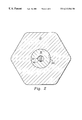
- FIG. 2 is a transverse sectional view of the embodiment of FIG. 1, taken along a line 2 — 2 of FIG. 1
- FIG. 3 is a longitudinal sectional view of an embodiment of the present invention in a second orientation.
- FIG. 4 is a longitudinal sectional view of an alternative embodiment of the present invention.
- FIG. 5 is a longitudinal sectional view of yet another alternative embodiment of the present invention.
- FIG. 6 is a longitudinal sectional view of yet another alternative embodiment of the present invention.
- the reference numeral 20 refers to a brake proportioning in-line valve of one embodiment of the present invention.
- the valve 20 has a generally hexagonal housing 21 which may be made of metal or other durable material.
- the housing 21 has an inlet end portion, depicted on the right as viewed in FIG. 1, and an outlet end portion, depicted on the left as viewed in FIG. 1 .
- the valve 20 is connected in a vehicle fluid braking system, with the inlet end portion connected to the outlet of a master cylinder, and the outlet end portion connected to at least one rear wheel brake cylinder, or caliper, as will be explained.
- An external threaded portion 21 a of the housing 21 and a staked edge 21 b of the housing 21 , are located at the inlet end portion.
- the housing 21 has an axial through bore 22 which is stepped along its length to form a series of sections 22 a - 22 e extending from the inlet end portion to the outlet end portion.
- the corresponding diameters of the sections 22 a - 22 d range from the largest to the smallest, respectively.
- the bore sections 22 a - 22 e may be produced by any conventional means, and define a series of shoulders or steps, 22 f , 22 g , and 22 h , at the junction of the sections 22 a and 22 b , sections 22 b and 22 c , and sections 22 c and 22 d , respectively.
- the section 22 e is internally threaded and adapted to mate with a hydraulic line (not shown), which operably connects to the rear wheel brakes.
- a cap is disposed in the housing 21 .
- the cap 28 is substantially T-shaped in cross section, and is held in a relatively tight fit between the housing step 22 f and the staked edge 21 b .
- the cap 28 includes a rounded edge 28 a adjacent to the staked edge 21 b to facilitate attachment. It is understood that any other conventional means may be used for retaining the cap 28 , such as a pressed in retainer. For reasons to be described, it is desirable that the attaching means allow air to pass between the cap 28 and the housing 21 .
- An inlet seat 28 b is formed in the cap 28 , and is inwardly tapered to register with an axial through bore 28 c .
- the exterior of the cap 28 further includes a flat surface 28 d oriented opposite the inlet seat 28 b for reasons to be described. A portion of the flat surface 28 d engages the step 22 f of the housing 21 , and the flat surface 28 d is located at an end of the area defined by the section 22 b of the housing 21 .
- the cap 28 includes an extension 28 e that extends into the bore section 22 b for reasons to be described.
- the extension 28 e is cylindrical in shape, with the cap bore 28 c extending axially throughout its length.
- An end 28 f of the extension includes a transverse slot 28 g .
- a radial stepped down portion 28 h of the extension is disposed approximately midway down the extension 28 e .
- An annular flange 28 i is formed on extension 28 e , and a seal 30 is disposed between the flange 28 i and the stepped down portion 28 h , for reasons to be described.
- a piston 32 is slidably mounted within the areas defined by the sections 22 b and 22 c of the housing 21 , and slidably extends over the cap extension 28 e .
- the piston 32 is cylindrical, and substantially Y-shaped in cross section, as will be explained.
- An annular flange 32 a is formed on the outer surface of the piston 32 .
- the outer surface of the piston 32 also has a radial groove 32 b which receives an outlet pressure elastomeric seal 34 , forming a seal between the piston 32 and the wall of the housing 21 defining the section 22 c .
- the seal 34 isolates the outlet brake fluid pressure in section 22 c to the left of the seal 34 , as viewed in FIG. 1, and therefore in sections 22 d and 22 e .
- the pressure outside the piston 32 to the right of the seal 34 is kept at atmospheric pressure because venting occurs at the joint between the cap 28 and the housing 21 .
- a relatively large bore 32 d is formed in the piston 32 and is connected, through a tapered bore, or seat, 32 e to a relatively small bore 32 f .
- the large bore 32 d extends over a portion of the cap extension 28 e .
- the inlet seal 30 engages the surface of the piston 32 defining the bore 32 d to isolate the brake fluid inlet pressure in the cap bore 28 c and the piston bore 32 d .
- the bore 32 f is subjected to the above described outlet pressure.
- a spring 36 extends between the flat surface 28 d of the cap 28 and the annular flange 32 a to bias the flange against the housing step 22 g .
- the diameter of the piston spring 36 is greater than the diameter of the bore section 22 c , for reasons to be described.
- the piston 32 moves between the position shown in FIG. 1 to an intermediate position between the position of FIG. 1 and a position in which an end 32 c of the piston 32 engages the flat surface 28 d of the cap 28 .
- An example of this intermediate position is shown in FIG. 3, it being understood that the term intermediate position defined herein means any position between the position of FIG. 1 and the position in which the end 32 c of the piston 32 engages the flat surface 28 d .
- the piston also has another end 32 g , disposed in bore section 22 c , as will be explained.
- a ball 38 is disposed in the large bore 32 d of the piston 32 .
- the ball 38 engages the seat 32 e , forming a seal.
- a spring 39 extends between the ball 38 and the annular flange 28 i of the cap 28 and over a portion of the cap extension 28 e . The spring 39 thus urges the ball 38 in a direction indicated by arrow B.
- a rod 40 in the form of a flat, rectangular piece of metal is disposed inside the small bore 32 f of the piston 32 .
- a first end 40 a of the rod 40 engages the ball 38
- a second end 40 b of the rod 40 engages the housing step 22 h.
- valve 20 is connected in a hydraulic braking system for a vehicle that includes a brake pedal operably attached to a master cylinder, which is connected to rear wheel brakes via hydraulic lines. Since all of the components, with the exception of the valve 20 , are conventional, they are not shown.
- depressing the brake pedal causes the master cylinder to produce increased hydraulic pressure.
- the brake proportioning valve 20 is disposed between the master cylinder and the rear wheel brakes to allow proportionately less hydraulic pressure from the master cylinder to reach the rear wheel brakes.
- An inlet pressure is developed in the inlet end portion as a result of increasing hydraulic pressure from the master cylinder when the brake pedal is applied.
- an outlet pressure is developed in the outlet end portion. Outlet pressure depends on the hydraulic equilibrium of the piston, the force associated with the piston spring, and increases or decreases in the inlet pressure.
- valve 20 At low inlet end portion pressures, where the brake is not applied, the valve 20 is in the position of FIG. 1 . In this position, brake fluid flows freely through the brake proportioning valve in directions indicated by arrows A and B, and therefore some brake fluid is present in the valve.
- the valve has a normal or passive first position, as illustrated in FIG. 1 .
- additional brake fluid enters the cap seat 28 b , and passes through the cap bore 28 c and into the large bore 32 d raising the inlet pressure, which, as noted above, is isolated by the seal 30 .
- the piston 32 As long as the piston 32 is in this position, fluid flows around the ball 38 , past the seat 32 e , past the rod 40 and through the bore 32 f , and through the sections 22 d and 22 e , and on to the rear wheel brakes. In this position, the inlet pressure is essentially equal to the outlet pressure.
- the outlet pressure correspondingly increases until the outlet pressure eventually reaches the above-defined knee point pressure, and creates a force acting on the end 32 g of the piston 32 that is sufficient to force the piston 32 in a direction, indicated by arrow A (to the right, as viewed in FIG. 1 ), overcoming the force of the spring 36 .
- the piston 32 moves to the intermediate position, as shown in FIG. 3, and thus the piston seat 32 e engages the ball 38 , stopping fluid flow.
- valve 20 allows fluid to flow freely to the rear wheel brakes at low master cylinder outlet hydraulic pressures and restricts the flow of brake fluid to the rear wheel brakes at predetermined higher master cylinder outlet hydraulic pressures, thereby achieving the proper braking proportion between the front and rear wheel brakes.
- the spring 36 surrounds the greater part of the piston 32 and, therefore, the inlet seal 30 and the ball 38 .
- the present invention results in a shorter valve length.
- the diameter of the piston spring 36 is greater than the diameter of the outlet seal 34 , resulting in more design options, including the ability to use stronger springs for producing higher knee points.
- this embodiment uses only two elastomeric seals, and thus reduces breakable components. Also, because the inlet seal 30 is disposed inside the piston 32 , whereas the outlet seal 34 is disposed outside the piston 32 , a more favorable differential is created between the area subjected to the inlet pressure and the area subjected to the outlet pressure, allowing a smaller valve to produce the same knee points as prior art methods.
- the housing 21 could be produced in a variety of shapes, and the transition from section to section of the bore 22 may be gradual instead of stepped.
- a one piece element could replace the ball 38 and rod 40 , having a first portion including a sealing surface shape, such as a ball or cone, and a second portion which is long and narrow.
- the ball spring 39 is depicted as a straight spring, however, a conical spring, or some other means of exerting force could be used.
- the ball 38 could be pushed far enough to engage the cap extension 28 e . If the ball 38 were pushed all the way to the end 28 f of the cap extension 28 e , the spring 39 would still not be fully compressed and the cross slot 28 g would allow fluid flow around the ball 38 as a second means to prevent undesirable flow restriction.
- the reference numeral 42 refers to a brake proportioning in-line valve of another embodiment of the present invention.
- This embodiment incorporates several components of the previous embodiment which are given the same reference numbers.
- the ball 38 is held in place by gravity and a cap 46 replaces the cap 28 of the previous embodiment.
- An extension 46 a of the cap 46 has an end 46 b which extends across the large bore 32 d .
- the valve must be oriented in a direction indicated by arrow C, so that gravity keeps the ball 38 engaged with the rod 40 .
- This embodiment has several advantages, including making the cap extension 46 a easier to machine because it has no annular flange, and minimizing flow restrictions because the brake fluid does not have to flow through a ball spring. By reducing flow restrictions, and eliminating the force associated with the ball spring, this embodiment further reduces hysteresis, the lag found when a fluid force changes direction.
- the reference numeral 48 refers to a brake proportioning in-line valve of another embodiment of the present invention.
- This embodiment incorporates several components of the first embodiment which are given the same reference numbers.
- a cap 50 is provided in place of the cap 28 of the embodiment of FIGS. 1-3.
- the cap 50 has a flat surface 50 a for mating with a fluid inlet.
- This embodiment could mate with a variety of fluid delivery systems, however, a passage in the system may be required for venting, and another sealing element (not shown) required on the valve 48 to prevent leakage.
- the reference numeral 52 refers to a brake proportioning in-line valve of another embodiment of the present invention.
- This embodiment incorporates several components of the first embodiment which are given the same reference numbers.
- the ball 38 and spring 39 of the embodiment of FIGS. 1-3 are replaced by a relatively large ball 54 and a spring 56 , respectively.
- the embodiment has a different pressure proportioning ratio than an embodiment using a smaller ball.
Landscapes
- Engineering & Computer Science (AREA)
- Transportation (AREA)
- Mechanical Engineering (AREA)
- Hydraulic Control Valves For Brake Systems (AREA)
- Multiple-Way Valves (AREA)
- Braking Arrangements (AREA)
- Taps Or Cocks (AREA)
- Valves And Accessory Devices For Braking Systems (AREA)
- Safety Valves (AREA)
- Accommodation For Nursing Or Treatment Tables (AREA)
- Prostheses (AREA)
Abstract
Description
Claims (31)
Priority Applications (8)
| Application Number | Priority Date | Filing Date | Title |
|---|---|---|---|
| US09/300,572 US6213566B1 (en) | 1999-04-27 | 1999-04-27 | Brake proportioning in-line ball valve |
| HK02105573.2A HK1043969B (en) | 1999-04-27 | 2000-03-07 | Brake proportioning in-line ball valve |
| PCT/US2000/005966 WO2000064718A1 (en) | 1999-04-27 | 2000-03-07 | Brake proportioning in-line ball valve |
| AT00914857T ATE314955T1 (en) | 1999-04-27 | 2000-03-07 | AXIAL BRAKE PROPORTIONING BALL VALVE |
| JP2000613685A JP2002542113A (en) | 1999-04-27 | 2000-03-07 | In-line ball valve for brake adjustment |
| AU36192/00A AU3619200A (en) | 1999-04-27 | 2000-03-07 | Brake proportioning in-line ball valve |
| EP00914857A EP1175321B1 (en) | 1999-04-27 | 2000-03-07 | Brake proportioning in-line ball valve |
| DE60025339T DE60025339D1 (en) | 1999-04-27 | 2000-03-07 | AXIAL BREMSPROPORTIONIERKUGELVENTIL |
Applications Claiming Priority (1)
| Application Number | Priority Date | Filing Date | Title |
|---|---|---|---|
| US09/300,572 US6213566B1 (en) | 1999-04-27 | 1999-04-27 | Brake proportioning in-line ball valve |
Publications (1)
| Publication Number | Publication Date |
|---|---|
| US6213566B1 true US6213566B1 (en) | 2001-04-10 |
Family
ID=23159667
Family Applications (1)
| Application Number | Title | Priority Date | Filing Date |
|---|---|---|---|
| US09/300,572 Expired - Fee Related US6213566B1 (en) | 1999-04-27 | 1999-04-27 | Brake proportioning in-line ball valve |
Country Status (8)
| Country | Link |
|---|---|
| US (1) | US6213566B1 (en) |
| EP (1) | EP1175321B1 (en) |
| JP (1) | JP2002542113A (en) |
| AT (1) | ATE314955T1 (en) |
| AU (1) | AU3619200A (en) |
| DE (1) | DE60025339D1 (en) |
| HK (1) | HK1043969B (en) |
| WO (1) | WO2000064718A1 (en) |
Cited By (4)
| Publication number | Priority date | Publication date | Assignee | Title |
|---|---|---|---|---|
| US6439083B1 (en) * | 2000-03-23 | 2002-08-27 | Dbm Innovation, Inc. | Universal spring tool |
| US6508520B2 (en) * | 2001-03-20 | 2003-01-21 | Delphi Technologies, Inc. | System and method of retaining a component in a hydraulic control unit housing |
| US20050052077A1 (en) * | 2003-09-05 | 2005-03-10 | Werner Quirant | Hydraulic brake system and method for controlling same |
| US20080292473A1 (en) * | 2006-01-31 | 2008-11-27 | Giuseppe Marino | High-Pressure Pump For Feeding Fuel To An Internal Combustion Engine |
Families Citing this family (1)
| Publication number | Priority date | Publication date | Assignee | Title |
|---|---|---|---|---|
| US6586131B2 (en) * | 2001-02-16 | 2003-07-01 | Wilson Greatbatch Ltd. | Apparatus for releasing gases from rechargeable lithium electrochemical cells during the formation stage of manufacturing |
Citations (17)
| Publication number | Priority date | Publication date | Assignee | Title |
|---|---|---|---|---|
| US3245221A (en) * | 1964-09-18 | 1966-04-12 | Budd Co | Brake proportioning valve |
| US3377108A (en) * | 1966-08-15 | 1968-04-09 | Bendix Corp | Brake proportioning device |
| US3781063A (en) * | 1971-04-28 | 1973-12-25 | Fiat Spa | Motor vehicle braking circuits |
| US4335922A (en) * | 1979-07-11 | 1982-06-22 | Itt Industries, Inc. | Pressure control unit |
| US4606583A (en) * | 1984-09-05 | 1986-08-19 | Allied Corporation | Brake system |
| US4637664A (en) * | 1984-07-31 | 1987-01-20 | Nippon A B S, Ltd. | Anti-skid control apparatus for a vehicle braking system |
| US4850651A (en) | 1988-09-06 | 1989-07-25 | Allied-Signal Inc. | Proportioning brake control valve with caged tare pressure spring |
| US4861114A (en) * | 1987-09-28 | 1989-08-29 | Sumitomo Electric Industries, Ltd. | Proportioning control valve for use with antilock device |
| US4893878A (en) | 1988-09-27 | 1990-01-16 | Hilite Industries, Inc. | Inline proportioning valve for brake systems |
| US5066072A (en) | 1989-08-23 | 1991-11-19 | Jidosha Kiki Co., Ltd. | Hydraulic brake pressure control valve |
| US5322354A (en) | 1992-02-07 | 1994-06-21 | Jidosha Kiki Co., Ltd. | Proportioning valve |
| US5362136A (en) | 1993-03-02 | 1994-11-08 | Midland Brake, Inc. | Proportioning module |
| US5462341A (en) | 1993-04-09 | 1995-10-31 | Jidosha Kiki Co., Ltd. | Proportioning valve |
| US5472266A (en) * | 1991-10-18 | 1995-12-05 | Itt Automotive Europe Gmbh | Anti-lock hydraulic brake system |
| US5522651A (en) | 1995-06-02 | 1996-06-04 | Kelsey Hayes Company | Brake proportioning valve |
| US5544946A (en) * | 1994-06-14 | 1996-08-13 | Honda Giken Kogyo Kabushiki Kaisha | Motorcycle braking system and method |
| US5741049A (en) | 1995-06-02 | 1998-04-21 | Kelsey-Hayes Company | Brake proportioning valve |
Family Cites Families (4)
| Publication number | Priority date | Publication date | Assignee | Title |
|---|---|---|---|---|
| US3954307A (en) * | 1974-01-21 | 1976-05-04 | Kelsey-Hayes Corporation | Load sensing proportioning valve including inertia responsive element |
| US4068900A (en) * | 1976-08-05 | 1978-01-17 | Kelsey-Hayes Co. | Blend back proportioning brake control apparatus |
| JPH07260037A (en) * | 1994-03-16 | 1995-10-13 | Toyota Motor Corp | Solenoid valve for fluid control |
| DE19529363A1 (en) * | 1995-08-10 | 1997-02-13 | Bosch Gmbh Robert | Controllable valve |
-
1999
- 1999-04-27 US US09/300,572 patent/US6213566B1/en not_active Expired - Fee Related
-
2000
- 2000-03-07 DE DE60025339T patent/DE60025339D1/en not_active Expired - Lifetime
- 2000-03-07 HK HK02105573.2A patent/HK1043969B/en not_active IP Right Cessation
- 2000-03-07 EP EP00914857A patent/EP1175321B1/en not_active Expired - Lifetime
- 2000-03-07 AT AT00914857T patent/ATE314955T1/en not_active IP Right Cessation
- 2000-03-07 WO PCT/US2000/005966 patent/WO2000064718A1/en not_active Ceased
- 2000-03-07 AU AU36192/00A patent/AU3619200A/en not_active Abandoned
- 2000-03-07 JP JP2000613685A patent/JP2002542113A/en active Pending
Patent Citations (17)
| Publication number | Priority date | Publication date | Assignee | Title |
|---|---|---|---|---|
| US3245221A (en) * | 1964-09-18 | 1966-04-12 | Budd Co | Brake proportioning valve |
| US3377108A (en) * | 1966-08-15 | 1968-04-09 | Bendix Corp | Brake proportioning device |
| US3781063A (en) * | 1971-04-28 | 1973-12-25 | Fiat Spa | Motor vehicle braking circuits |
| US4335922A (en) * | 1979-07-11 | 1982-06-22 | Itt Industries, Inc. | Pressure control unit |
| US4637664A (en) * | 1984-07-31 | 1987-01-20 | Nippon A B S, Ltd. | Anti-skid control apparatus for a vehicle braking system |
| US4606583A (en) * | 1984-09-05 | 1986-08-19 | Allied Corporation | Brake system |
| US4861114A (en) * | 1987-09-28 | 1989-08-29 | Sumitomo Electric Industries, Ltd. | Proportioning control valve for use with antilock device |
| US4850651A (en) | 1988-09-06 | 1989-07-25 | Allied-Signal Inc. | Proportioning brake control valve with caged tare pressure spring |
| US4893878A (en) | 1988-09-27 | 1990-01-16 | Hilite Industries, Inc. | Inline proportioning valve for brake systems |
| US5066072A (en) | 1989-08-23 | 1991-11-19 | Jidosha Kiki Co., Ltd. | Hydraulic brake pressure control valve |
| US5472266A (en) * | 1991-10-18 | 1995-12-05 | Itt Automotive Europe Gmbh | Anti-lock hydraulic brake system |
| US5322354A (en) | 1992-02-07 | 1994-06-21 | Jidosha Kiki Co., Ltd. | Proportioning valve |
| US5362136A (en) | 1993-03-02 | 1994-11-08 | Midland Brake, Inc. | Proportioning module |
| US5462341A (en) | 1993-04-09 | 1995-10-31 | Jidosha Kiki Co., Ltd. | Proportioning valve |
| US5544946A (en) * | 1994-06-14 | 1996-08-13 | Honda Giken Kogyo Kabushiki Kaisha | Motorcycle braking system and method |
| US5522651A (en) | 1995-06-02 | 1996-06-04 | Kelsey Hayes Company | Brake proportioning valve |
| US5741049A (en) | 1995-06-02 | 1998-04-21 | Kelsey-Hayes Company | Brake proportioning valve |
Cited By (6)
| Publication number | Priority date | Publication date | Assignee | Title |
|---|---|---|---|---|
| US6439083B1 (en) * | 2000-03-23 | 2002-08-27 | Dbm Innovation, Inc. | Universal spring tool |
| US6508520B2 (en) * | 2001-03-20 | 2003-01-21 | Delphi Technologies, Inc. | System and method of retaining a component in a hydraulic control unit housing |
| US20050052077A1 (en) * | 2003-09-05 | 2005-03-10 | Werner Quirant | Hydraulic brake system and method for controlling same |
| US7201455B2 (en) * | 2003-09-05 | 2007-04-10 | Robert Bosch, Gmbh | Hydraulic brake system and method for controlling same |
| US20080292473A1 (en) * | 2006-01-31 | 2008-11-27 | Giuseppe Marino | High-Pressure Pump For Feeding Fuel To An Internal Combustion Engine |
| US7871251B2 (en) * | 2006-01-31 | 2011-01-18 | Robert Bosch Gmbh | High-pressure pump for feeding fuel to an internal combustion engine |
Also Published As
| Publication number | Publication date |
|---|---|
| JP2002542113A (en) | 2002-12-10 |
| ATE314955T1 (en) | 2006-02-15 |
| EP1175321A1 (en) | 2002-01-30 |
| EP1175321B1 (en) | 2006-01-04 |
| WO2000064718A1 (en) | 2000-11-02 |
| HK1043969A1 (en) | 2002-10-04 |
| DE60025339D1 (en) | 2006-03-30 |
| HK1043969B (en) | 2006-07-28 |
| AU3619200A (en) | 2000-11-10 |
| EP1175321A4 (en) | 2002-11-06 |
Similar Documents
| Publication | Publication Date | Title |
|---|---|---|
| US8256216B2 (en) | Vehicular brake apparatus | |
| US4053186A (en) | Proportional valve apparatus for use in a rear brake system of a vehicle | |
| US6846408B2 (en) | Filter assembly for a control valve in a vehicular brake system | |
| CA2627617A1 (en) | Combined service brake and spring-loaded brake cylinder with an inner ventilation | |
| US6213566B1 (en) | Brake proportioning in-line ball valve | |
| US4838305A (en) | Pressure differential valve | |
| US5741049A (en) | Brake proportioning valve | |
| US3964795A (en) | Modular proportioner | |
| EP0049969B1 (en) | A master cylinder assembly for a vehicle hydraulic braking system | |
| US7182413B2 (en) | Valve seat for a control valve in a vehicle brake system | |
| US5462341A (en) | Proportioning valve | |
| JPH0142862B2 (en) | ||
| US4008925A (en) | Valve devices for use in liquid pressure braking systems of vehicles | |
| US4265490A (en) | Pressure control valve for a vehicle hydraulic brake system | |
| US4255932A (en) | Tandem master cylinder | |
| US4416490A (en) | Pressure control valve for a hydraulic brake system | |
| US4744219A (en) | Master cylinder | |
| GB2056003A (en) | Dual circuit hydraulic control devices | |
| US5052760A (en) | Hydraulic proportioning valve | |
| JPH03295747A (en) | Brake hydraulic control device | |
| US6766644B2 (en) | Master cylinder with by-pass function and proportioning valve | |
| JPH106950A (en) | Hydraulic pressure control valve | |
| EP0084719A1 (en) | Brake pressure proportioning valve | |
| JPS5846925Y2 (en) | hydraulic control valve | |
| US3848619A (en) | Improvements in pressure-responsive hydraulic control valve assemblies |
Legal Events
| Date | Code | Title | Description |
|---|---|---|---|
| AS | Assignment |
Owner name: HILITE INDUSTRIES AUTOMOTIVE, LP, TEXAS Free format text: ASSIGNMENT OF ASSIGNORS INTEREST;ASSIGNOR:DIAZ, JUAN;REEL/FRAME:009946/0048 Effective date: 19990426 |
|
| FPAY | Fee payment |
Year of fee payment: 4 |
|
| AS | Assignment |
Owner name: NATIONAL CITY BANK, AS COLLATERAL AGENT, OHIO Free format text: SECURITY INTEREST;ASSIGNOR:HILITE INDUSTRIES-TEXAS, INC.;REEL/FRAME:016470/0798 Effective date: 20050408 |
|
| AS | Assignment |
Owner name: HILITE INDUSTRIES-TEXAS, INC., OHIO Free format text: RELEASE OF SECURITY INTEREST IN PATENT COLLATERAL AT REEL 016470 FRAME 0798;ASSIGNOR:NATIONAL CITY BANK;REEL/FRAME:019605/0516 Effective date: 20070725 |
|
| AS | Assignment |
Owner name: BEAR STEARNS CORPORATE LENDING INC., AS COLLATERAL Free format text: FIRST LIEN INTELLECTUAL PROPERTY SECURITY AGREEMENT;ASSIGNOR:HILITE INDUSTRIES-TEXAS, INC.;REEL/FRAME:019781/0204 Effective date: 20070725 |
|
| AS | Assignment |
Owner name: BEAR STEARNS CORPORATE LENDING INC., AS COLLATERAL Free format text: SECOND LIEN INTELLECTUAL PROPERTY SECURITY AGREEMENT;ASSIGNOR:HILITE INDUSTRIES-TEXAS, INC.;REEL/FRAME:019795/0528 Effective date: 20070725 |
|
| REMI | Maintenance fee reminder mailed | ||
| LAPS | Lapse for failure to pay maintenance fees | ||
| STCH | Information on status: patent discontinuation |
Free format text: PATENT EXPIRED DUE TO NONPAYMENT OF MAINTENANCE FEES UNDER 37 CFR 1.362 |
|
| FP | Lapsed due to failure to pay maintenance fee |
Effective date: 20090410 |
|
| AS | Assignment |
Owner name: ACUTEX, INC., OHIO Free format text: RELEASE OF SECURITY INTERESTS AT REEL/FRAME 019781/0191, 019781/0204, AND 019783/0524;ASSIGNOR:BEAR STEARNS CORPORATE LENDING, INC.;REEL/FRAME:023486/0806 Effective date: 20091105 Owner name: HILITE INDUSTRIES AUTOMOTIVE, LP, TEXAS Free format text: RELEASE OF SECURITY INTERESTS AT REEL/FRAME 019781/0191, 019781/0204, AND 019783/0524;ASSIGNOR:BEAR STEARNS CORPORATE LENDING, INC.;REEL/FRAME:023486/0806 Effective date: 20091105 Owner name: HILITE INTERNATIONAL, INC., TEXAS Free format text: RELEASE OF SECURITY INTERESTS AT REEL/FRAME 019781/0191, 019781/0204, AND 019783/0524;ASSIGNOR:BEAR STEARNS CORPORATE LENDING, INC.;REEL/FRAME:023486/0806 Effective date: 20091105 Owner name: HILITE INDUSTRIES-TEXAS, INC., OHIO Free format text: RELEASE OF SECURITY INTERESTS AT REEL/FRAME 019781/0191, 019781/0204, AND 019783/0524;ASSIGNOR:BEAR STEARNS CORPORATE LENDING, INC.;REEL/FRAME:023486/0806 Effective date: 20091105 Owner name: HILITE INDUSTRIES AUTOMOTIVE, LP, TEXAS Free format text: RELEASE OF SECURITY INTEREST AT REEL/FRAME 019795/0528;ASSIGNOR:BEAR STEARNS CORPORATE LENDING, INC.;REEL/FRAME:023486/0811 Effective date: 20091105 Owner name: HILITE INDUSTRIES-TEXAS, INC., OHIO Free format text: RELEASE OF SECURITY INTEREST AT REEL/FRAME 019795/0528;ASSIGNOR:BEAR STEARNS CORPORATE LENDING, INC.;REEL/FRAME:023486/0811 Effective date: 20091105 Owner name: HILITE INTERNATIONAL, INC., TEXAS Free format text: RELEASE OF SECURITY INTEREST AT REEL/FRAME 019795/0528;ASSIGNOR:BEAR STEARNS CORPORATE LENDING, INC.;REEL/FRAME:023486/0811 Effective date: 20091105 |
|
| AS | Assignment |
Owner name: JPMORGAN CHASE BANK, N.A., NEW YORK Free format text: FIRST LIEN INTELLECTUAL PROPERTY SECURITY AGREEMENT;ASSIGNORS:ACUTEX, INC.;HILITE INDUSTRIES AUTOMOTIVE, LP;HILITE INTERNATIONAL, INC.;REEL/FRAME:023498/0359 Effective date: 20091105 Owner name: JPMORGAN CHASE BANK, N.A., NEW YORK Free format text: SECOND LIEN INTELLECTUAL PROPERTY SECURITY AGREEMENT;ASSIGNORS:ACUTEX, INC.;HILITE INDUSTRIES AUTOMOTIVE, LP;HILITE INTERNATIONAL, INC.;REEL/FRAME:023498/0378 Effective date: 20091105 |
|
| AS | Assignment |
Owner name: HILITE INDUSTRIES AUTOMOTIVE, LP, TEXAS Free format text: RELEASE OF SECURITY INTEREST IN PATENT COLLATERAL;ASSIGNOR:JPMORGAN CHASE BANK N.A.;REEL/FRAME:026553/0713 Effective date: 20110628 Owner name: ACUTEX, INC., OHIO Free format text: RELEASE OF SECURITY INTEREST IN PATENT COLLATERAL;ASSIGNOR:JPMORGAN CHASE BANK N.A.;REEL/FRAME:026553/0713 Effective date: 20110628 Owner name: HYDRAULIK-RING GMBH, GERMANY Free format text: RELEASE OF SECURITY INTEREST IN PATENT COLLATERAL;ASSIGNOR:JPMORGAN CHASE BANK N.A.;REEL/FRAME:026553/0713 Effective date: 20110628 Owner name: HILITE INTERNATIONAL INC., OHIO Free format text: RELEASE OF SECURITY INTEREST IN PATENT COLLATERAL;ASSIGNOR:JPMORGAN CHASE BANK N.A.;REEL/FRAME:026553/0713 Effective date: 20110628 |