US6212702B1 - SPA cover kit - Google Patents
SPA cover kit Download PDFInfo
- Publication number
- US6212702B1 US6212702B1 US09/294,777 US29477799A US6212702B1 US 6212702 B1 US6212702 B1 US 6212702B1 US 29477799 A US29477799 A US 29477799A US 6212702 B1 US6212702 B1 US 6212702B1
- Authority
- US
- United States
- Prior art keywords
- cap
- spa
- support posts
- attached
- dual hinged
- Prior art date
- Legal status (The legal status is an assumption and is not a legal conclusion. Google has not performed a legal analysis and makes no representation as to the accuracy of the status listed.)
- Expired - Fee Related
Links
- 230000009977 dual effect Effects 0.000 claims abstract description 29
- 239000011152 fibreglass Substances 0.000 claims abstract description 4
- 239000000463 material Substances 0.000 abstract description 7
- 210000003195 fascia Anatomy 0.000 description 5
- 239000003562 lightweight material Substances 0.000 description 3
- 229910000831 Steel Inorganic materials 0.000 description 2
- 230000000087 stabilizing effect Effects 0.000 description 2
- 239000010959 steel Substances 0.000 description 2
- 229920004142 LEXAN™ Polymers 0.000 description 1
- 239000004418 Lexan Substances 0.000 description 1
- 238000010276 construction Methods 0.000 description 1
- 230000000694 effects Effects 0.000 description 1
- 238000012986 modification Methods 0.000 description 1
- 230000004048 modification Effects 0.000 description 1
- 239000004033 plastic Substances 0.000 description 1
- 239000004431 polycarbonate resin Substances 0.000 description 1
- 229920005668 polycarbonate resin Polymers 0.000 description 1
Images


Classifications
-
- E—FIXED CONSTRUCTIONS
- E04—BUILDING
- E04H—BUILDINGS OR LIKE STRUCTURES FOR PARTICULAR PURPOSES; SWIMMING OR SPLASH BATHS OR POOLS; MASTS; FENCING; TENTS OR CANOPIES, IN GENERAL
- E04H4/00—Swimming or splash baths or pools
- E04H4/06—Safety devices; Coverings for baths
- E04H4/08—Coverings consisting of rigid elements, e.g. coverings composed of separate or connected elements
Definitions
- This invention relates to convertible enclosures, and more particularly, to such enclosures for outdoor spas.
- covers should be elevated structures so that users of the spa may stand up in a fully upright position.
- the cover should be a sufficient size to slightly extend over the sides of the spa to protect users sitting on the edge of the spa.
- the cover should be made of strong, durable material capable of withstanding normal weather conditions.
- these covers are relatively heavy structures made of standard-size lumber which are cut and assembled on site by three or more individuals. What is needed is a spa cover made of lightweight materials that is pre-fabricated and distributed in a kit for easy assembly by only two individuals.
- the cover includes a square or rectangular-shaped cap pivotally attached at two corners to two dual hinged support posts and at the opposite corners to two fixed support posts.
- the cap is a single unit made of lightweight, weather-proof material, such as fiberglass, which fully extends across a standard size spa.
- the lower end of each dual hinged support post is pivotally attached to the deck adjacent to the corners on the spa.
- the opposite, upper end of each dual hinged support post is pivotally attached to one corner of the cap.
- the upper hinge means and lower hinge means are aligned on each dual hinged support post so that the cap may simultaneously pivot on the upper and lower hinge means as the dual hinged support posts pivotally rotate from a horizontal to a vertical orientation on the deck when positioning the cap over the spa. This feature is especially useful because it allows one or two workers to easily assemble the cover over the spa.
- the free, unsupported side of the cap can be comfortably supported by one worker.
- the two fixed support posts are then selected, vertically aligned, and securely attached to the two unsupported corners on the cap.
- the lower ends of the two fixed support posts are then securely attached to the deck while the upper ends of the two fixed support posts are attached to the cap.
- Optional, diagonally aligned cross-braces can then be attached between the cap and each support post to further stabilize the cap.
- the system may also include optional cover extensions that attach directly to the sides of the cap to provide additional covered areas.
- Each extension cover includes a lightweight cap and a pair of legs that can be easily and quickly installed.
- FIG. 1 is a perspective view of the spa cover system completely set up and extended over a spa.
- FIG. 2 is a side elevational view of the spa cover system taken along line 2 — 2 shown in FIG. 1 .
- FIG. 3 is a sectional, side elevational view of a section of the cap with a block insert attached to one corner with the upper end of the dual hinged support post pivotally attached thereto and the lower end pivotally attached to the deck.
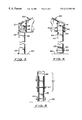
- FIG. 4 is a sectional, side elevational view of a section of the cap with the upper end of the fixed support post attached thereto and the lower end fixed to the deck.
- FIG. 5 is a sectional, side elevational view of the adjustable, fixed support post.
- FIGS. 6-8 are illustrations showing two individuals positioning and assembling the cover over the spa.
- FIG. 9 is a top plan view of the spa cover with two optional extensions attached to two adjacent sides of the cap system.
- FIGS. 1-9 Shown in the accompanying FIGS. 1-9 is a spa cover kit 10 designed to be installed over an existing outdoor spa 8 .
- the kit 10 comprises a cap 20 having overall dimensions slightly larger than a standard-sized spa 8 (8′ ⁇ 8′) capable of covering a spa 8 , two dual hinged support posts 30 , two fixed support posts 40 and attaching hardware further described herein.
- the cap 20 is a single, prefabricated structure made of a lightweight, weather-proof material, such as molded fiberglass.
- the cap 20 is pyramidal and includes four converging support ribs with four skylight openings 23 formed between them.
- Skylights 23 are made of a lightweight plastic material, such as LEXAN, a polycarbonate resin sheet material made by General Electric Corporation of New York, N.Y.
- the two dual hinged support posts 30 are pivotally attached at their upper ends to the corners located on one side of the cap 8 by an upper hinge means.
- the upper hinge means comprises a leaf hinge 32 disposed between the upper end of the support post 30 and a wooden block 28 inserted into the pocket 24 formed on the corner of the cap 20 .
- the lower ends of the dual hinged support posts 30 are attached to the deck surface 90 adjacent to the comer of the spa 8 via a lower hinge means.
- the lower hinge means is a leaf hinge 34 with one leaf attached directly to the deck adjacent to a corner on one side of the spa 8 .
- the two fixed support posts 40 are designed to be selectively attached to the corners opposite the dual hinged support posts 30 after the cap 20 is disposed over the spa 8 .
- the upper end 41 of each fixed support post 40 is inserted into a cavity formed on the corner of the cap 20 .
- Two perpendicularly aligned bolts 55 are then inserted through holes formed on the front and side fascia 26 of the cap 20 .
- the fixed support posts 40 are securely attached to the deck 90 using U-shaped holding brackets 42 and bolts 55 .
- Optional stabilizing straps 49 may be attached between each support post 30 and 40 and the fascias on the cap 20 .
- the support posts 30 , 40 are made of steel (2 ⁇ 2) tubing approximately 84 inches in length.
- the stabilizing straps 49 are approximately 11 ⁇ 2 inches in width and 24 inches in length.
- the two dual hinged support posts 30 are aligned in a horizontal parallel position on one side of the spa 8 as shown in FIG. 6 .
- the lower ends of the two support posts 30 are then attached to the leaf hinges 34 , which, in turn, are attached to the deck 90 adjacent to two corners on the spa 8 .
- the cap 20 is then selected and held in a vertical position so that the wooden blocks 28 located on the two corners 22 may be connected to the upper ends of the two dual hinged support posts 30 .
- the upper ends of the dual hinged support posts 30 and corners 22 are connected together via the leaf hinge 32 .
- the two dual hinged support posts 30 and the cap 20 are slowly lifted so that the dual hinged support posts 30 are disposed in an upright, vertical position and the cap 20 is disposed over the spa 8 .
- the cap 20 and support posts 30 are made of lightweight material, one worker 92 is usually able to properly position the cap 20 over the spa 8 .
- the worker 92 is able to hold the detached side of the cap 20 so that the fixed support posts 40 may be attached by a second worker 94 .
- the fixed support posts 40 are selected, the upper ends are inserted into the receiving pockets 24 located on the corners 22 of the cap 20 . As shown more clearly in FIG.
- the upper end of the fixed support posts 40 are attached to the cap 20 using bolts 48 that extend from the fascia 26 , through the support post 40 and to the inside surface of the pocket 24 .
- the lower end 43 of the fixed support posts 40 are attached to a lower bracket 44 attached to the top surface of the deck 90 .
- the fixed support posts 40 may include a length adjustment means so that the cap 20 may be properly aligned in a horizontal orientation over the spa 8 .
- the length adjustment means includes a lower telescopic leg 45 that slides longitudinally inside the lower end opening of the receiving leg 46 .
- a bolt 47 is inserted through holes formed on the telescopic leg 45 and the receiving leg 46 to affix the legs 45 , 46 in a fixed position.
- the kit 10 is designed to be used with one or more optional extension covers 50 to provide additional protection over the spa.
- an optional extension cover 50 may be attached to the front or side fascias 23 of the cap 20 to provide additional covered area around the spa 8 .
- the extension cover 50 includes an extension cap 51 , a pair of fixed support posts 53 , and connecting bolts 55 .
- the extension cap 51 has a length approximately equal to the length of the cap 20 .
- the extension cap 51 is a flat roof design made of durable, lightweight material similar to the cap 20 .
- the support posts 52 are made of steel tubing material similar to the fixed support post 40 .
- the upper ends of the fixed support posts 52 are placed into pockets 54 located in the corners of the extension cap 51 .
- the lower ends of the fixed support posts 52 are securely attached to the deck 90 via brackets and bolts (both not shown).
- Bolts 58 are then used to attach the adjoining fascia surfaces 21 , 53 of the cap 20 and the extension cap 51 , respectively, together.
Landscapes
- Engineering & Computer Science (AREA)
- Architecture (AREA)
- Civil Engineering (AREA)
- Structural Engineering (AREA)
- Tents Or Canopies (AREA)
Abstract
Description
Claims (3)
Priority Applications (1)
| Application Number | Priority Date | Filing Date | Title |
|---|---|---|---|
| US09/294,777 US6212702B1 (en) | 1999-04-19 | 1999-04-19 | SPA cover kit |
Applications Claiming Priority (1)
| Application Number | Priority Date | Filing Date | Title |
|---|---|---|---|
| US09/294,777 US6212702B1 (en) | 1999-04-19 | 1999-04-19 | SPA cover kit |
Publications (1)
| Publication Number | Publication Date |
|---|---|
| US6212702B1 true US6212702B1 (en) | 2001-04-10 |
Family
ID=23134913
Family Applications (1)
| Application Number | Title | Priority Date | Filing Date |
|---|---|---|---|
| US09/294,777 Expired - Fee Related US6212702B1 (en) | 1999-04-19 | 1999-04-19 | SPA cover kit |
Country Status (1)
| Country | Link |
|---|---|
| US (1) | US6212702B1 (en) |
Cited By (10)
| Publication number | Priority date | Publication date | Assignee | Title |
|---|---|---|---|---|
| US6718566B1 (en) | 2002-09-24 | 2004-04-13 | Jerry A. Wilson | Vertically adjustable spa cover assembly |
| FR2852990A1 (en) * | 2003-03-25 | 2004-10-01 | Technal | Swimming pool shelter structure assembly part, has connection units with crossbeam mounted on sliding unit of shelter and curved lintel inserted in curved section delimiting outer edge of sliding unit |
| US20050108817A1 (en) * | 2003-11-25 | 2005-05-26 | Wilson Jerry A. | Collapsable spa enclosure |
| US20060032156A1 (en) * | 2004-07-22 | 2006-02-16 | Jean Simard | Openable roof |
| US20080244820A1 (en) * | 2007-04-06 | 2008-10-09 | Scott Moore | Soft bimini style gazebo particularly in use with separate and independently actuating hard top cover flipper |
| US20090114259A1 (en) * | 2007-11-01 | 2009-05-07 | Habing Theodore G | Covered play apparatus |
| US20090308422A1 (en) * | 2008-06-12 | 2009-12-17 | Scott Rizzotto | Outdoor spa covering device |
| US20090307834A1 (en) * | 2008-06-12 | 2009-12-17 | Scott Rizzotto | Spa covering device |
| US20100065371A1 (en) * | 2008-09-17 | 2010-03-18 | Glenn Paul F | Tree stand protection system |
| US12595650B2 (en) | 2023-02-28 | 2026-04-07 | A&C Future, Inc. | Outdoor to indoor swimming pool apparatus |
Citations (14)
| Publication number | Priority date | Publication date | Assignee | Title |
|---|---|---|---|---|
| US2912703A (en) * | 1957-11-04 | 1959-11-17 | William A Murphy | Swimming pool cover |
| US3051964A (en) * | 1960-06-08 | 1962-09-04 | Edward G Fisher | Combination sun shade and pool cover |
| US3464373A (en) * | 1967-02-28 | 1969-09-02 | Larson Co Charles O | Folding leg assembly |
| US3807104A (en) | 1972-05-31 | 1974-04-30 | Reynolds Metals Co | Foldable portable structure |
| US3854149A (en) * | 1973-06-21 | 1974-12-17 | R Mischke | Sun canopy convertible to a swimming pool cover |
| US4051638A (en) | 1976-08-05 | 1977-10-04 | Heintz Robert J | Removable enclosure for a swimming pool or the like |
| US4068423A (en) | 1976-03-01 | 1978-01-17 | Marsh Edwin R | Simplified greenhouse structure suitable for mass production and field assembly |
| US4136408A (en) | 1976-11-24 | 1979-01-30 | Dahlbeck Edwin L | Lightweight removable cover for a pool, greenhouse or the like |
| US4246663A (en) | 1979-09-17 | 1981-01-27 | Aragona Anthony J | Hot tub cover |
| US4404980A (en) * | 1980-09-30 | 1983-09-20 | James Nemec | Arched support structure with cover |
| USD280438S (en) | 1983-05-04 | 1985-09-03 | Wendt Gary R | Hot tub cover |
| US5148646A (en) | 1991-08-08 | 1992-09-22 | Lutostanski Leonard A | Convertible enclosure for hot tubs and the like |
| US5606831A (en) * | 1995-05-25 | 1997-03-04 | Tippmann; Joseph R. | Enclosed monolithic swimming pool |
| US5745932A (en) | 1996-11-22 | 1998-05-05 | Barovetto; David L. | Hot tub cover and enclosure |
-
1999
- 1999-04-19 US US09/294,777 patent/US6212702B1/en not_active Expired - Fee Related
Patent Citations (14)
| Publication number | Priority date | Publication date | Assignee | Title |
|---|---|---|---|---|
| US2912703A (en) * | 1957-11-04 | 1959-11-17 | William A Murphy | Swimming pool cover |
| US3051964A (en) * | 1960-06-08 | 1962-09-04 | Edward G Fisher | Combination sun shade and pool cover |
| US3464373A (en) * | 1967-02-28 | 1969-09-02 | Larson Co Charles O | Folding leg assembly |
| US3807104A (en) | 1972-05-31 | 1974-04-30 | Reynolds Metals Co | Foldable portable structure |
| US3854149A (en) * | 1973-06-21 | 1974-12-17 | R Mischke | Sun canopy convertible to a swimming pool cover |
| US4068423A (en) | 1976-03-01 | 1978-01-17 | Marsh Edwin R | Simplified greenhouse structure suitable for mass production and field assembly |
| US4051638A (en) | 1976-08-05 | 1977-10-04 | Heintz Robert J | Removable enclosure for a swimming pool or the like |
| US4136408A (en) | 1976-11-24 | 1979-01-30 | Dahlbeck Edwin L | Lightweight removable cover for a pool, greenhouse or the like |
| US4246663A (en) | 1979-09-17 | 1981-01-27 | Aragona Anthony J | Hot tub cover |
| US4404980A (en) * | 1980-09-30 | 1983-09-20 | James Nemec | Arched support structure with cover |
| USD280438S (en) | 1983-05-04 | 1985-09-03 | Wendt Gary R | Hot tub cover |
| US5148646A (en) | 1991-08-08 | 1992-09-22 | Lutostanski Leonard A | Convertible enclosure for hot tubs and the like |
| US5606831A (en) * | 1995-05-25 | 1997-03-04 | Tippmann; Joseph R. | Enclosed monolithic swimming pool |
| US5745932A (en) | 1996-11-22 | 1998-05-05 | Barovetto; David L. | Hot tub cover and enclosure |
Cited By (11)
| Publication number | Priority date | Publication date | Assignee | Title |
|---|---|---|---|---|
| US6718566B1 (en) | 2002-09-24 | 2004-04-13 | Jerry A. Wilson | Vertically adjustable spa cover assembly |
| FR2852990A1 (en) * | 2003-03-25 | 2004-10-01 | Technal | Swimming pool shelter structure assembly part, has connection units with crossbeam mounted on sliding unit of shelter and curved lintel inserted in curved section delimiting outer edge of sliding unit |
| US20050108817A1 (en) * | 2003-11-25 | 2005-05-26 | Wilson Jerry A. | Collapsable spa enclosure |
| US20060032156A1 (en) * | 2004-07-22 | 2006-02-16 | Jean Simard | Openable roof |
| US20080244820A1 (en) * | 2007-04-06 | 2008-10-09 | Scott Moore | Soft bimini style gazebo particularly in use with separate and independently actuating hard top cover flipper |
| US20090114259A1 (en) * | 2007-11-01 | 2009-05-07 | Habing Theodore G | Covered play apparatus |
| US7721747B2 (en) * | 2007-11-01 | 2010-05-25 | Dream Visions, Llc | Covered play apparatus |
| US20090308422A1 (en) * | 2008-06-12 | 2009-12-17 | Scott Rizzotto | Outdoor spa covering device |
| US20090307834A1 (en) * | 2008-06-12 | 2009-12-17 | Scott Rizzotto | Spa covering device |
| US20100065371A1 (en) * | 2008-09-17 | 2010-03-18 | Glenn Paul F | Tree stand protection system |
| US12595650B2 (en) | 2023-02-28 | 2026-04-07 | A&C Future, Inc. | Outdoor to indoor swimming pool apparatus |
Similar Documents
| Publication | Publication Date | Title |
|---|---|---|
| US9316019B2 (en) | Adjustable tarpaulin support | |
| US6604327B1 (en) | Retractable spa enclosure | |
| US11591820B2 (en) | Sunshade tent | |
| EP1516981B1 (en) | Screen room enclosure and method of attachment thereof | |
| US4777755A (en) | Portable hunting blind and shelter | |
| US6212702B1 (en) | SPA cover kit | |
| US4719716A (en) | Round deer stand | |
| US8393343B2 (en) | Railing mounted shade | |
| US10030445B2 (en) | Tri-truss self-closing gate | |
| US8087422B2 (en) | Canopy with ventilation | |
| US20160108638A1 (en) | System and Method for a Portable Wind Break Device | |
| US6827094B1 (en) | Shielding assembly | |
| US20090308422A1 (en) | Outdoor spa covering device | |
| US8099803B2 (en) | Method of using clips for retrofit installation of a portable swimming pool barrier fence | |
| US6058660A (en) | Portable garage | |
| JP3375897B2 (en) | Awning equipment | |
| CN215331854U (en) | Waterproof car roof tent support structure | |
| US7389573B2 (en) | Method of retrofit installation of a portable swimming pool barrier fence | |
| US20040250475A1 (en) | Door frame kit | |
| AU724718B3 (en) | Car shelter | |
| JPH05148965A (en) | Column with built-in vertical gutter | |
| CN224093084U (en) | Outdoor multifunctional waterproof leisure awning | |
| CN217518351U (en) | Ellipsoidal covering or awning on a car, boat, etc. room | |
| US20070056222A1 (en) | Extendable support braces for a screened enclosure | |
| KR20040011057A (en) | The portable fishing pedestal which used a profile |
Legal Events
| Date | Code | Title | Description |
|---|---|---|---|
| AS | Assignment |
Owner name: SITZMANN, DEREK, WASHINGTON Free format text: ASSIGNMENT OF ASSIGNORS INTEREST;ASSIGNOR:SITZMANN, KEITH;REEL/FRAME:010760/0787 Effective date: 20000413 Owner name: SITZMANN, AARON, WASHINGTON Free format text: ASSIGNMENT OF ASSIGNORS INTEREST;ASSIGNOR:SITZMANN, KEITH;REEL/FRAME:010760/0787 Effective date: 20000413 Owner name: SITZMANN, BEAU, VIRGINIA Free format text: ASSIGNMENT OF ASSIGNORS INTEREST;ASSIGNOR:SITZMANN, KEITH;REEL/FRAME:010760/0787 Effective date: 20000413 |
|
| REMI | Maintenance fee reminder mailed | ||
| AS | Assignment |
Owner name: PENN STATE RESEARCH FOUNDATION, THE, PENNSYLVANIA Free format text: ASSIGNMENT OF ASSIGNORS INTEREST;ASSIGNORS:MEYER, RICHARD JOSEPH, JR.;HUGHS, WILLIAM JACK;REEL/FRAME:016038/0020 Effective date: 20030115 |
|
| LAPS | Lapse for failure to pay maintenance fees | ||
| STCH | Information on status: patent discontinuation |
Free format text: PATENT EXPIRED DUE TO NONPAYMENT OF MAINTENANCE FEES UNDER 37 CFR 1.362 |
|
| FP | Lapsed due to failure to pay maintenance fee |
Effective date: 20050410 |