US5737806A - Apparatus for treating fiber and producing a fiber lap therefrom - Google Patents
Apparatus for treating fiber and producing a fiber lap therefrom Download PDFInfo
- Publication number
- US5737806A US5737806A US08/735,948 US73594896A US5737806A US 5737806 A US5737806 A US 5737806A US 73594896 A US73594896 A US 73594896A US 5737806 A US5737806 A US 5737806A
- Authority
- US
- United States
- Prior art keywords
- fiber
- licker
- fiber material
- doffer
- receiving
- Prior art date
- Legal status (The legal status is an assumption and is not a legal conclusion. Google has not performed a legal analysis and makes no representation as to the accuracy of the status listed.)
- Expired - Fee Related
Links
- 239000000835 fiber Substances 0.000 title claims abstract description 55
- 238000009960 carding Methods 0.000 claims abstract description 37
- 239000002657 fibrous material Substances 0.000 claims abstract description 33
- 238000007664 blowing Methods 0.000 claims 1
- 239000002699 waste material Substances 0.000 description 9
- 230000001105 regulatory effect Effects 0.000 description 4
- 239000007795 chemical reaction product Substances 0.000 description 2
- 238000004140 cleaning Methods 0.000 description 2
- 239000000203 mixture Substances 0.000 description 2
- 238000007789 sealing Methods 0.000 description 2
- 238000011144 upstream manufacturing Methods 0.000 description 2
- 229920000742 Cotton Polymers 0.000 description 1
- 230000001154 acute effect Effects 0.000 description 1
- 230000006978 adaptation Effects 0.000 description 1
- 238000010276 construction Methods 0.000 description 1
- 238000010586 diagram Methods 0.000 description 1
- 230000009977 dual effect Effects 0.000 description 1
- 239000000428 dust Substances 0.000 description 1
- 230000000694 effects Effects 0.000 description 1
- 239000012634 fragment Substances 0.000 description 1
- 230000001939 inductive effect Effects 0.000 description 1
- 239000000463 material Substances 0.000 description 1
- 238000012986 modification Methods 0.000 description 1
- 230000004048 modification Effects 0.000 description 1
- 239000010813 municipal solid waste Substances 0.000 description 1
- 239000002245 particle Substances 0.000 description 1
- 239000000047 product Substances 0.000 description 1
- 230000000630 rising effect Effects 0.000 description 1
- 238000000926 separation method Methods 0.000 description 1
- 230000002195 synergetic effect Effects 0.000 description 1
Images


Classifications
-
- D—TEXTILES; PAPER
- D01—NATURAL OR MAN-MADE THREADS OR FIBRES; SPINNING
- D01G—PRELIMINARY TREATMENT OF FIBRES, e.g. FOR SPINNING
- D01G23/00—Feeding fibres to machines; Conveying fibres between machines
- D01G23/02—Hoppers; Delivery shoots
- D01G23/04—Hoppers; Delivery shoots with means for controlling the feed
-
- D—TEXTILES; PAPER
- D01—NATURAL OR MAN-MADE THREADS OR FIBRES; SPINNING
- D01G—PRELIMINARY TREATMENT OF FIBRES, e.g. FOR SPINNING
- D01G15/00—Carding machines or accessories; Card clothing; Burr-crushing or removing arrangements associated with carding or other preliminary-treatment machines
- D01G15/02—Carding machines
- D01G15/12—Details
- D01G15/14—Constructional features of carding elements, e.g. for facilitating attachment of card clothing
- D01G15/20—Feed rollers; Takers-in
-
- D—TEXTILES; PAPER
- D01—NATURAL OR MAN-MADE THREADS OR FIBRES; SPINNING
- D01G—PRELIMINARY TREATMENT OF FIBRES, e.g. FOR SPINNING
- D01G15/00—Carding machines or accessories; Card clothing; Burr-crushing or removing arrangements associated with carding or other preliminary-treatment machines
- D01G15/02—Carding machines
- D01G15/12—Details
- D01G15/34—Grids; Dirt knives; Angle blades
Definitions
- This invention relates to an apparatus for making a fiber lap, particularly from cotton fibers.
- U.S. Pat. No. 5,303,455 issued Apr. 19, 1994 is directed to a fiber treating apparatus in which a fiber lap feeder introduces fiber material to a cleaner formed of three consecutively arranged cleaning rolls.
- the fiber material is removed by an air stream for the last cleaning roll and is, in a chamber, deposited on a perforated belt whose underside is exposed to a vacuum stream.
- the perforated belt discharges the cleaned fiber material onto a removal belt in the form of a fiber lap.
- the apparatus for treating fiber and producing a fiber lap therefrom includes a fiber feeder; a carding machine including a multi-roll licker-in assembly receiving the fiber material from the feeder, a main carding cylinder receiving fiber material from the licker-in assembly, a plurality of carding flats supported about a circumferential portion of the main carding cylinder and cooperating therewith, and a doffer receiving fiber material from the main carding cylinder; and a fiber lap forming device including a pneumatic fiber stripping device which has a blower for directing an airstream generally tangentially to the doffer for removing and entraining fiber material from the doffer, a hood having an inner face defining a chamber situated above and downstream of said doffer for receiving fiber material carried from the doffer by the airstream, a continuously driven, air-pervious receiving member having an upper face and an underside, and a suction device facing the underside of
- the invention resides in the combination of part of the construction disclosed in U.S. Pat. No. 5,303,455 and parent application Ser. No. 08/448,679, resulting in an improved product which can be regarded as a result of a synergistic effect of a combination of the two systems.
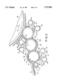
- FIG. 1 is a schematic sectional side elevational view of a preferred embodiment of the invention.
- FIG. 2 is a schematic sectional side elevational view of some of the components of the preferred embodiment of the invention.
- FIG. 3 is a fragmentary sectional side elevational view of a variant of the card feeder shown in FIG. 1.
- FIG. 4 is a schematic sectional side elevational view of another preferred embodiment of the invention.
- FIG. 5 is a sectional side elevational view, with block diagram, of another preferred embodiment of the card feeder shown in FIG. 1.
- FIG. 1 there is illustrated therein a known fiber tuft feeder 1 which may be, for example, an EXACTAFEED FBK model, manufactured by Trutzschler GmbH & Co. KG, Monchengladbach, Germany.
- the fiber tuft feeder 1 has an upper, reserve chute 2 and a lower, feed chute 3 between which a feed roll 4 and an opening roll 5 are positioned, which forward the fiber material A from the reserve chute 2 into the feed chute 3.
- a fan 6 drives air tangentially past the opening roll 5 into the feed chute 3 for forming an air/fiber mixture B and for densifying the fiber column which builds up in the feed chute 3.
- the air driven by the fan 6 is recirculated by withdrawing air through apertures 7 provided in a lower part of the feed chute 3.
- a feeding device 12 composed of a feed roller 13 and a feed table 14 of a conventional carding machine CM which may be, for example, an EXACTACARD DK 760 model, manufactured by Trutzschler GmbH & Co. KG, Monchengladbach, Germany.
- the feed roller 13 and the feed table 14 are followed by three serially arranged licker-ins 15, 16 and 17 forming a licker-in assembly 18, a main carding cylinder 19 and a doffer 20.
- the carding cylinder 19 has a sawtooth clothing 21 and rotates in the direction designated with the arrow C.
- the carding cylinder 19 cooperates with stationary flats 22, composed of stationary flats segments 22a-22e covering one part of the upper circumference of the carding cylinder 19.
- the clothings 23a-23e of the flats segments 22a-22e and the clothing 21 of the carding cylinder 19 cooperate with one another to form a carding zone.
- the flats segments 22a-22e are, as viewed in the circumferential direction, at a clearance from one another.
- the flats segments are, as viewed in the circumferential direction, at a clearance from one another.
- the flats segments are, as viewed in the circumferential direction, at a clearance from one another.
- the flats segments are, as viewed in the circumferential direction, at a clearance from one another.
- the flats segments are, as viewed in the circumferential direction, at a clearance from one another.
- in front of each flats segment--as viewed in the direction of rotation of the carding cylinder 19--respective mote knives 24a-24e are provided to separate waste, trash and the like.
- Each mote knife is associated with a respective suction hood 25a-25e.
- the cutting edge of the mote knives is in each instance oriented opposite the rotary direction C of the carding cylinder 19.
- the distance of the mote knives to the carding cylinder determines the intensity of the waste
- microdust finest dust particles
- the setting distance may lie between 0.1 and 2.5 mm.
- the fiber lap 11, held firmly between the feed table 14 and the feed roller 13 is, by virtue of the rotation of the feed roller 13 in the direction of the arrow D, advanced slowly in the direction of the rapidly rotating licker-in 15 which is a pin roll.
- the pins 15a of the pin roll 15 penetrate into the fiber lap 11 and remove fibers which are further transported by the pins 15a.
- the pin roll 15 rotates with a significantly higher speed than the feed roll 13 in a direction indicated by the arrow E, that is, opposite to the direction of rotation D of the feed roll 13.
- the removed fibers pass by the waste discharge opening 26 where at the separating edge 27a of the mote knife 27 waste is removed which is further transported away by a suction device 28.
- the fibers pass through a stationary carding element 29 before further waste removal is effected by the separating edge 30a of a mote knife 30. Waste is discharged through the discharge opening 31, aided by the suction device 32. Then the fiber material moves onto the subsequent licker-in 16 which is provided with a sawtooth clothing 16a.
- the licker-in 16 too, is provided with waste discharge openings 33, 34, mote knives 35, 36 and suction devices 37, 38.
- the licker-in 16 rotates at a higher speed than the licker-in 15.
- the licker-in 16 which rotates in the direction of the arrow F transfers the fibers to the licker-in 17 rotating in the opposite direction as indicated by the arrow G.
- the licker-in 17 too, is provided with a sawtooth clothing 17a which, however, is finer than that on the licker-in 16.
- the licker-in 17, which is associated with waste discharge openings 39, 40, mote knives 41, 42 and suction devices 43, 44, transfers the fibers to the carding cylinder 19.
- the waste discharge openings 34 and 40 are preceded by respective stationary carding elements 45 and 56, respectively. All the licker-ins 15, 16 and 17 are provided with covers 47, 48, and 49 to the extent possible.
- FIG. 3 illustrates the modified downstream end of the fiber tuft feeder 1.
- the delivery rolls 8 and 9 are replaced by a single feed roller 50 which, in cooperation with a feed tray 51 forming a terminus of the feed chute 3, advances the fiber lap to the licker-in 15 of the carding machine CM (not shown in FIG. 3).
- the feed roller 50 has the dual role of withdrawing the fiber material from the feed chute 3 and advancing it directly to the licker-in 15.
- the carding machine CM of FIG. 1, having stationary flats 22a-22e is replaced by a carding machine CM' provided with conventional travelling flats generally designated at 52.
- the doffer 20 of the carding machine CM is associated with a pneumatic fiber-stripping device generally designated at 60 for ejecting the fibers upwardly from the doffer 20.
- a pneumatic fiber-stripping device generally designated at 60 for ejecting the fibers upwardly from the doffer 20.
- an endless screen belt 61 is arranged, supported by end rollers 62 and 63.
- the screen belt 61 is inclined upwardly at an angle ⁇ to the horizontal in the working direction.
- a downwardly open hood 64 is provided which encloses a receiving chamber 65 into which the fiber is thrown from the doffer 20 by the stripping device 60.
- the hood 64 has an inner wall surface portion 64a which extends upwardly from the doffer 20 and which is inclined at an angle ⁇ to the vertical and extends over the screen belt 61.
- the inner wall surface 64a is inclined toward the screen belt 61 at an acute angle of 90-( ⁇ + ⁇ ) degrees.
- the upper end of the inner wall surface 64a is adjoined by a curved inner wall surface 64b closing the hood 64 and terminating adjacent the upper end of the screen belt 61.
- the fiber material is guided by the air stream of the stripping device 60 along the rising inner wall surface portion 64a of the hood 64 and is directed as an air/fiber mixture, in a distribution shown by arrows H, onto the upper surface of the working flight 61a of the screen belt 61.
- a fiber lap removal device 66 comprising, for example, a conveyor belt, is arranged downstream of the screen belt 61.
- the fiber stripping device 60 is arranged tangentially to the doffer 20 and directs an air stream K in the upward direction.
- the underside of the working flight 61a of the screen belt 61 is exposed to suction by serially arranged suction boxes 67a, 67b and 67c which are coupled to a common suction conduit 68 by individual suction conduits 69a, 69b and 69c, respectively.
- Each suction conduit 69a, 69b and 69c accommodates a respective throttle gate 70a, 70b and 70c for setting the flow rate of the suction stream for each suction box 67a, 67b and 67c.
- a fan 71 which supplies, in recirculation, the stripping air stream K, the conveying air stream H as well as the suction air stream L.
- a sealing roller 72 which is situated between the upper face of the belt flight 61a and a terminal edge 64c of the hood 64 to obturate the clearance between the belt 61 and the hood 64.
- a sealing roller 73 is provided which obturates the space between the outlet of the stripping device 60 and the screen belt 61.
- two cooperating calender rollers 74 and 75 are provided.
- the screen belt it is feasible to use a rotary screen drum which is exposed to suction by a vacuum device situated inside the drum.
- a device 80 for regulating the thickness of a preliminary fiber lap is situated immediately upstream of the input side (represented by the licker-in 15) of the carding machine CM.
- the measuring member 81 cooperates with an inductive path sensor 82 which, in turn, is electrically connected with a control and regulating device 83.
- a pressure sensor 84 arranged in the horizontal feed chute 85 applies sensor signals via a transducer 86 to the control and regulating device 83.
- the latter controls a speed variable motor 87 which operates the feed roller 88 functioning as the feed roller 50 of FIG. 3.
- the control and regulating device 83 also controls a pneumatic cylinder unit 89 for varying the width of the feed chute 85 in the zone of the air outlet openings 90, as well as the rpm of a motor 91 driving the feed roll 4 of the fiber tuft feeder 1'.
Landscapes
- Engineering & Computer Science (AREA)
- Textile Engineering (AREA)
- Preliminary Treatment Of Fibers (AREA)
Abstract
An apparatus for treating fiber and producing a fiber lap therefrom, includes a fiber feeder; a carding machine including a multi-roll licker-in assembly receiving the fiber material from the feeder, a main carding cylinder receiving fiber material from the licker-in assembly, a plurality of carding flats supported about a circumferential portion of the main carding cylinder and cooperating therewith, and a doffer receiving fiber material from the main carding cylinder; and a fiber lap forming device including a pneumatic fiber stripping device which has a blower for directing an airstream generally tangentially to the doffer for removing and entraining fiber material from the doffer, a hood having an inner face defining a chamber situated above and downstream of said doffer for receiving fiber material carried from the doffer by the airstream, a continuously driven, air-pervious receiving member having an upper face and an underside, and a suction device facing the underside of the receiving member for generating an airstream passing through the receiving member in a direction from the upper face to the underside for drawing fiber material in the chamber onto the upper face of the receiving member for forming a fiber lap thereon.
Description
This application is a continuation-in-part of application Ser. No. 08/448,679 filed May 24, 1995, now abandoned.
This invention relates to an apparatus for making a fiber lap, particularly from cotton fibers.
U.S. Pat. No. 5,303,455 issued Apr. 19, 1994 is directed to a fiber treating apparatus in which a fiber lap feeder introduces fiber material to a cleaner formed of three consecutively arranged cleaning rolls. The fiber material is removed by an air stream for the last cleaning roll and is, in a chamber, deposited on a perforated belt whose underside is exposed to a vacuum stream. The perforated belt discharges the cleaned fiber material onto a removal belt in the form of a fiber lap.
It has been found that for producing certain articles, particularly for hygienic purposes, from a fiber cleaned in the above-outlined manner too many and excessively large neps are present and further, the material to be processed is cloudy and lacks the desired uniformity.
Similar disadvantages were found in the end product of a carding machine constructed in accordance with parent application Ser. No. 08/448,679.
It is an object of the invention to provide an improved apparatus whose end product has a significantly improved opening effect, a better reduction of the quantity and size of neps and also a significantly improved uniformity of the fiber lap.
This object and others to become apparent as the specification progresses, are accomplished by the invention, according to which, briefly stated, the apparatus for treating fiber and producing a fiber lap therefrom, includes a fiber feeder; a carding machine including a multi-roll licker-in assembly receiving the fiber material from the feeder, a main carding cylinder receiving fiber material from the licker-in assembly, a plurality of carding flats supported about a circumferential portion of the main carding cylinder and cooperating therewith, and a doffer receiving fiber material from the main carding cylinder; and a fiber lap forming device including a pneumatic fiber stripping device which has a blower for directing an airstream generally tangentially to the doffer for removing and entraining fiber material from the doffer, a hood having an inner face defining a chamber situated above and downstream of said doffer for receiving fiber material carried from the doffer by the airstream, a continuously driven, air-pervious receiving member having an upper face and an underside, and a suction device facing the underside of the receiving member for generating an airstream passing through the receiving member in a direction from the upper face to the underside for drawing fiber material in the chamber onto the upper face of the receiving member for forming a fiber lap thereon.
Thus, essentially, the invention resides in the combination of part of the construction disclosed in U.S. Pat. No. 5,303,455 and parent application Ser. No. 08/448,679, resulting in an improved product which can be regarded as a result of a synergistic effect of a combination of the two systems.
FIG. 1 is a schematic sectional side elevational view of a preferred embodiment of the invention.
FIG. 2 is a schematic sectional side elevational view of some of the components of the preferred embodiment of the invention.
FIG. 3 is a fragmentary sectional side elevational view of a variant of the card feeder shown in FIG. 1.
FIG. 4 is a schematic sectional side elevational view of another preferred embodiment of the invention.
FIG. 5 is a sectional side elevational view, with block diagram, of another preferred embodiment of the card feeder shown in FIG. 1.
Turning to FIG. 1, there is illustrated therein a known fiber tuft feeder 1 which may be, for example, an EXACTAFEED FBK model, manufactured by Trutzschler GmbH & Co. KG, Monchengladbach, Germany. The fiber tuft feeder 1 has an upper, reserve chute 2 and a lower, feed chute 3 between which a feed roll 4 and an opening roll 5 are positioned, which forward the fiber material A from the reserve chute 2 into the feed chute 3. A fan 6 drives air tangentially past the opening roll 5 into the feed chute 3 for forming an air/fiber mixture B and for densifying the fiber column which builds up in the feed chute 3. The air driven by the fan 6 is recirculated by withdrawing air through apertures 7 provided in a lower part of the feed chute 3. At the bottom end of the feed chute 3 cooperating delivery rolls 8 and 9 are provided which withdraw the fiber material from the feed chute 3 and forward the same onto a guide tray 10 on which the fiber material is, as a preliminary fiber lap 11, advanced to a feeding device 12 composed of a feed roller 13 and a feed table 14 of a conventional carding machine CM which may be, for example, an EXACTACARD DK 760 model, manufactured by Trutzschler GmbH & Co. KG, Monchengladbach, Germany.
The feed roller 13 and the feed table 14 are followed by three serially arranged licker- ins 15, 16 and 17 forming a licker-in assembly 18, a main carding cylinder 19 and a doffer 20.
The carding cylinder 19 has a sawtooth clothing 21 and rotates in the direction designated with the arrow C. The carding cylinder 19 cooperates with stationary flats 22, composed of stationary flats segments 22a-22e covering one part of the upper circumference of the carding cylinder 19. The clothings 23a-23e of the flats segments 22a-22e and the clothing 21 of the carding cylinder 19 cooperate with one another to form a carding zone.
Between the flats segments 22a-22e a space is provided, that is, the flats segments are, as viewed in the circumferential direction, at a clearance from one another. In each instance, in front of each flats segment--as viewed in the direction of rotation of the carding cylinder 19--respective mote knives 24a-24e are provided to separate waste, trash and the like. Each mote knife is associated with a respective suction hood 25a-25e. The cutting edge of the mote knives is in each instance oriented opposite the rotary direction C of the carding cylinder 19. The distance of the mote knives to the carding cylinder determines the intensity of the waste separation. In case of a very small distance, in addition to shell fragments and short fibers the finest dust particles (microdust) are also removed. In case of a larger distance of the mote knives from the carding cylinder less microdust is removed. The setting distance may lie between 0.1 and 2.5 mm.
Turning to FIG. 2, the fiber lap 11, held firmly between the feed table 14 and the feed roller 13 is, by virtue of the rotation of the feed roller 13 in the direction of the arrow D, advanced slowly in the direction of the rapidly rotating licker-in 15 which is a pin roll. The pins 15a of the pin roll 15 penetrate into the fiber lap 11 and remove fibers which are further transported by the pins 15a. The pin roll 15 rotates with a significantly higher speed than the feed roll 13 in a direction indicated by the arrow E, that is, opposite to the direction of rotation D of the feed roll 13. The removed fibers pass by the waste discharge opening 26 where at the separating edge 27a of the mote knife 27 waste is removed which is further transported away by a suction device 28. Thereafter, the fibers pass through a stationary carding element 29 before further waste removal is effected by the separating edge 30a of a mote knife 30. Waste is discharged through the discharge opening 31, aided by the suction device 32. Then the fiber material moves onto the subsequent licker-in 16 which is provided with a sawtooth clothing 16a. The licker-in 16 too, is provided with waste discharge openings 33, 34, mote knives 35, 36 and suction devices 37, 38. The licker-in 16 rotates at a higher speed than the licker-in 15.
The licker-in 16 which rotates in the direction of the arrow F transfers the fibers to the licker-in 17 rotating in the opposite direction as indicated by the arrow G. The licker-in 17 too, is provided with a sawtooth clothing 17a which, however, is finer than that on the licker-in 16. The licker-in 17, which is associated with waste discharge openings 39, 40, mote knives 41, 42 and suction devices 43, 44, transfers the fibers to the carding cylinder 19. The waste discharge openings 34 and 40 are preceded by respective stationary carding elements 45 and 56, respectively. All the licker- ins 15, 16 and 17 are provided with covers 47, 48, and 49 to the extent possible.
FIG. 3 illustrates the modified downstream end of the fiber tuft feeder 1. In this arrangement the delivery rolls 8 and 9 are replaced by a single feed roller 50 which, in cooperation with a feed tray 51 forming a terminus of the feed chute 3, advances the fiber lap to the licker-in 15 of the carding machine CM (not shown in FIG. 3). Thus, the feed roller 50 has the dual role of withdrawing the fiber material from the feed chute 3 and advancing it directly to the licker-in 15.
In the embodiment according to FIG. 4, the carding machine CM of FIG. 1, having stationary flats 22a-22e is replaced by a carding machine CM' provided with conventional travelling flats generally designated at 52.
Reverting to FIG. 1, the doffer 20 of the carding machine CM is associated with a pneumatic fiber-stripping device generally designated at 60 for ejecting the fibers upwardly from the doffer 20. Downstream of the fiber-stripping device 60 an endless screen belt 61 is arranged, supported by end rollers 62 and 63. The screen belt 61 is inclined upwardly at an angle α to the horizontal in the working direction. Above the screen belt 61 a downwardly open hood 64 is provided which encloses a receiving chamber 65 into which the fiber is thrown from the doffer 20 by the stripping device 60. The hood 64 has an inner wall surface portion 64a which extends upwardly from the doffer 20 and which is inclined at an angle β to the vertical and extends over the screen belt 61. Thus, the inner wall surface 64a is inclined toward the screen belt 61 at an acute angle of 90-(α+β) degrees. The upper end of the inner wall surface 64a is adjoined by a curved inner wall surface 64b closing the hood 64 and terminating adjacent the upper end of the screen belt 61. The fiber material is guided by the air stream of the stripping device 60 along the rising inner wall surface portion 64a of the hood 64 and is directed as an air/fiber mixture, in a distribution shown by arrows H, onto the upper surface of the working flight 61a of the screen belt 61. A fiber lap removal device 66 comprising, for example, a conveyor belt, is arranged downstream of the screen belt 61.
The fiber stripping device 60 is arranged tangentially to the doffer 20 and directs an air stream K in the upward direction. The underside of the working flight 61a of the screen belt 61 is exposed to suction by serially arranged suction boxes 67a, 67b and 67c which are coupled to a common suction conduit 68 by individual suction conduits 69a, 69b and 69c, respectively. Each suction conduit 69a, 69b and 69c accommodates a respective throttle gate 70a, 70b and 70c for setting the flow rate of the suction stream for each suction box 67a, 67b and 67c.
Between the suction conduit 68 and the fiber stripping device 60 a fan 71 is provided which supplies, in recirculation, the stripping air stream K, the conveying air stream H as well as the suction air stream L. At the discharge end of the screen belt 61 there is provided, between the end roller 63 and the lower boundary of the receiving chamber 65, a sealing roller 72 which is situated between the upper face of the belt flight 61a and a terminal edge 64c of the hood 64 to obturate the clearance between the belt 61 and the hood 64. Further, at the upstream end of the screen belt 61, between the fiber stripping device 60 and the doffer 20, a sealing roller 73 is provided which obturates the space between the outlet of the stripping device 60 and the screen belt 61. Between the screen belt 61 and the fiber lap removing device 66 two cooperating calender rollers 74 and 75 are provided. As an alternative to the screen belt, it is feasible to use a rotary screen drum which is exposed to suction by a vacuum device situated inside the drum.
Turning to FIG. 5, in the embodiment illustrated therein a device 80 for regulating the thickness of a preliminary fiber lap is situated immediately upstream of the input side (represented by the licker-in 15) of the carding machine CM. The measuring member 81 cooperates with an inductive path sensor 82 which, in turn, is electrically connected with a control and regulating device 83. Further, a pressure sensor 84 arranged in the horizontal feed chute 85 applies sensor signals via a transducer 86 to the control and regulating device 83. The latter, in turn, controls a speed variable motor 87 which operates the feed roller 88 functioning as the feed roller 50 of FIG. 3. The control and regulating device 83 also controls a pneumatic cylinder unit 89 for varying the width of the feed chute 85 in the zone of the air outlet openings 90, as well as the rpm of a motor 91 driving the feed roll 4 of the fiber tuft feeder 1'.
It will be understood that the above description of the present invention is susceptible to various modifications, changes and adaptations, and the same are intended to be comprehended within the meaning and range of equivalents of the appended claims.
Claims (8)
1. An apparatus for treating fiber and producing a fiber lap therefrom, comprising in combination
(a) fiber feeding means for advancing fiber material in a feeding direction;
(b) a carding machine including
(1) a licker-in assembly disposed downstream of said fiber feeding means as viewed in said feeding direction for receiving the fiber material from said feeding means; said licker-in assembly including at least two licker-ins arranged in a series in said feeding direction; any said licker-in cooperating as a take-over and opening roll with an immediately upstream-arranged said licker-in as viewed in said feeding direction;
(2) a main carding cylinder receiving fiber material from said licker-in assembly;
(3) a plurality of carding flats supported about a circumferential portion of said main carding cylinder and cooperating therewith; and
(4) a doffer receiving fiber material from said main carding cylinder; and
(c) a fiber lap forming device including
(1) a pneumatic fiber stripping device including blowing means for directing an airstream generally tangentially to the doffer for removing and entraining fiber material from said doffer;
(2) a hood having an inner face defining a chamber situated above and downstream of said doffer for receiving fiber material carried from said doffer by said airstream;
(3) an air-pervious receiving member having an upper face and an underside; said receiving member being disposed in said chamber downstream of said doffer;
(4) means for continuously moving said receiving member; and
(5) suction means facing said underside of said receiving member for generating an airstream passing through said receiving member in a direction from said upper face to said underside for drawing fiber material in said chamber onto said upper face of said receiving member for forming a fiber lap thereon.
2. The apparatus as defined in claim 1, wherein said carding flats are stationary flats.
3. The apparatus as defined in claim 1, wherein said carding flats are travelling flats.
4. The apparatus as defined in claim 1, wherein said licker-ins consist of a first, second and third licker-in as viewed in said feeding direction.
5. The apparatus as defined in claim 4, wherein said first licker-in is a pin roll and said second and third licker-ins are sawtooth rolls.
6. The apparatus as defined in claim 1, wherein said fiber feeding means comprises
(a) a card feeder having a feed chute having a discharge end and a pair of cooperating withdrawing rollers situated at said discharge end for pulling fiber material out of said feed chute; and
(b) a feed roller receiving fiber material from said withdrawing rollers and introducing the fiber material directly into said licker-in assembly.
7. The apparatus as defined in claim 1, wherein said fiber feeding means comprises a card feeder including a feed chute having a discharge end and a withdrawing roller situated at said discharge end for pulling fiber material out of said feed chute and for introducing the fiber material directly into said licker-in assembly.
8. The apparatus as defined in claim 1, wherein said lap forming device further comprises a device for removing said fiber lap from said receiving member.
Priority Applications (1)
| Application Number | Priority Date | Filing Date | Title |
|---|---|---|---|
| US08/735,948 US5737806A (en) | 1994-05-26 | 1996-10-23 | Apparatus for treating fiber and producing a fiber lap therefrom |
Applications Claiming Priority (4)
| Application Number | Priority Date | Filing Date | Title |
|---|---|---|---|
| DE19944418377 DE4418377A1 (en) | 1994-05-26 | 1994-05-26 | Device on a card, especially for cotton, man-made fibers and. the like |
| DE4418377.1 | 1994-05-26 | ||
| US44867995A | 1995-05-24 | 1995-05-24 | |
| US08/735,948 US5737806A (en) | 1994-05-26 | 1996-10-23 | Apparatus for treating fiber and producing a fiber lap therefrom |
Related Parent Applications (1)
| Application Number | Title | Priority Date | Filing Date |
|---|---|---|---|
| US44867995A Continuation-In-Part | 1994-05-26 | 1995-05-24 |
Publications (1)
| Publication Number | Publication Date |
|---|---|
| US5737806A true US5737806A (en) | 1998-04-14 |
Family
ID=25936897
Family Applications (1)
| Application Number | Title | Priority Date | Filing Date |
|---|---|---|---|
| US08/735,948 Expired - Fee Related US5737806A (en) | 1994-05-26 | 1996-10-23 | Apparatus for treating fiber and producing a fiber lap therefrom |
Country Status (1)
| Country | Link |
|---|---|
| US (1) | US5737806A (en) |
Cited By (17)
| Publication number | Priority date | Publication date | Assignee | Title |
|---|---|---|---|---|
| EP0989213A1 (en) * | 1998-09-04 | 2000-03-29 | Maschinenfabrik Rieter Ag | Carding machine respectively woolen carding machine |
| US6061877A (en) * | 1997-02-28 | 2000-05-16 | Trutzschler Gmbh & Co. Kg | Clothing for a roll advancing fiber material |
| US6185787B1 (en) * | 1997-07-30 | 2001-02-13 | Maschinenfabrik Rieter Ag | Fiber flock cleaner |
| US6195845B1 (en) * | 1998-04-17 | 2001-03-06 | Thibeau | Method and an installation for forming a fiber web by the airlay technique |
| US6279201B1 (en) * | 1998-03-20 | 2001-08-28 | Valmet Fibertech Ab | Device for distributing particles |
| ES2164506A1 (en) * | 1998-09-23 | 2002-02-16 | Pikolin Sa | Procedure for manufacturing elasto-resistant leather for tapestry |
| US6370736B1 (en) * | 1999-02-13 | 2002-04-16 | TRüTZSCHLER GMBH & CO. KG | Device for removing air from a pneumatically charged fiber tuft feeder |
| US6539586B2 (en) * | 2000-09-30 | 2003-04-01 | Trutzschler Gmbh & Co. Kg | Trash removal assembly in a fiber processing machine |
| US6568037B2 (en) * | 2000-12-11 | 2003-05-27 | TRüTZSCHLER GMBH & CO. KG | Apparatus for separating waste and short fibers from a carding cylinder |
| US20030154572A1 (en) * | 2002-02-20 | 2003-08-21 | Gerd Pferdmenges | Multi-element separation modules for a fiber processing machine |
| US20140034399A1 (en) * | 2012-08-06 | 2014-02-06 | Oskar Dilo Masc hinenfabrik KG | Feed Device for Supplying Individualized Fibers or Fiber Flocks to a Transport Device |
| CN104372456A (en) * | 2014-10-25 | 2015-02-25 | 浙江卓怡纺织有限公司 | Air pressure cotton box |
| CN105088427A (en) * | 2015-08-14 | 2015-11-25 | 青岛东佳纺机(集团)有限公司 | Sheep wool opening and carding complete equipment |
| CN105297190A (en) * | 2015-11-27 | 2016-02-03 | 山东宏业纺织股份有限公司 | Cleaning device for carding machine |
| US20170211209A1 (en) * | 2016-01-26 | 2017-07-27 | Saldarini 1882 S.R.L. | Method for filling a fillable portion of a garment to be padded and padded garment |
| US20180355520A1 (en) * | 2017-06-08 | 2018-12-13 | Maschinenfabrik Rieter Ag | Pressure Regulation in a Flock Feed |
| US20210148021A1 (en) * | 2017-09-06 | 2021-05-20 | Fisi Fibre Sintetiche S.P.A. | Free fibre padding structure and method for the production thereof |
Citations (25)
| Publication number | Priority date | Publication date | Assignee | Title |
|---|---|---|---|---|
| US2181535A (en) * | 1938-02-14 | 1939-11-28 | Spinnfaser Ag | Production of sliver |
| DE819373C (en) * | 1949-10-04 | 1951-10-31 | Emil Dr-Ing E H Gminder | Method and device for preparing bast fibers for carding |
| GB1278045A (en) * | 1968-06-18 | 1972-06-14 | Carding Spec Canada | Improvements in or relating to carding machines |
| US3729290A (en) * | 1971-10-04 | 1973-04-24 | P Dillies | Process and apparatus for the treatment of loose materials such as textile fibers |
| US3862472A (en) * | 1973-01-05 | 1975-01-28 | Scott Paper Co | Method for forming a low basis weight non-woven fibrous web |
| DE3003110A1 (en) * | 1979-03-07 | 1980-09-11 | Estebanell Juan B | DEVICE FOR CLEANING, OPENING AND COMBING TEXTILE FIBERS |
| US4314387A (en) * | 1978-10-23 | 1982-02-09 | Hollingsworth Gmbh | Dirt separator |
| US4414710A (en) * | 1978-11-09 | 1983-11-15 | Bolen George F | Textile carding machine feed assembly and method |
| DE3346092A1 (en) * | 1982-12-23 | 1984-07-19 | Olin Sylvester Greenville S.C. Elliott jun. | CRACKLE AND CRACKING PROCEDURE |
| US4539728A (en) * | 1982-10-07 | 1985-09-10 | Portell Jose E | Cards |
| US4706338A (en) * | 1985-03-12 | 1987-11-17 | Chicopee | Apparatus for forming fibre webs |
| US4761857A (en) * | 1985-12-13 | 1988-08-09 | Wool Research Organisation Of New Zealand Inc. | Method and apparatus for making long-tailed neps |
| US4785505A (en) * | 1986-03-14 | 1988-11-22 | Trutzschler Gmbh & Co. Kg | Silver or lap evening apparatus for a carding machine or the like |
| GB2214535A (en) * | 1988-02-12 | 1989-09-06 | Truetzschler & Co | Carding machine and method of carding |
| GB2228495A (en) * | 1989-01-26 | 1990-08-29 | Truetzschler & Co | Separation of waste in a carding machine |
| EP0423856A1 (en) * | 1989-09-27 | 1991-04-24 | FRATELLI MARZOLI & C. S.p.A. | Carding apparatus for textile materials |
| DE3940073A1 (en) * | 1989-12-04 | 1991-06-06 | Rieter Ag Maschf | TEASEL |
| US5022121A (en) * | 1987-09-30 | 1991-06-11 | Hollingsworth Gmbh | Carding machine or scribbler with transversely moving carding element sets |
| US5033165A (en) * | 1988-08-02 | 1991-07-23 | Trutzschler Gmbh & Co. Kg | Apparatus for opening and cleaning fiber material |
| DE4130147A1 (en) * | 1990-09-17 | 1992-03-19 | Truetzschler & Co | Cotton card-room equipment - has multipurpose and adjustable cross elements to partly cover each swift |
| US5255415A (en) * | 1990-09-17 | 1993-10-26 | Trutzschler Gmbh & Co. Kg | Integral common duct with suction hoods for waste removal |
| DE9218356U1 (en) * | 1992-09-22 | 1994-01-13 | Trützschler GmbH & Co KG, 41199 Mönchengladbach | Device on a card, especially for cotton, man-made fibers and the like. |
| DE4331284A1 (en) * | 1992-09-22 | 1994-03-24 | Truetzschler Gmbh & Co Kg | Carding machine with multiple licker-in rollers |
| GB2271126A (en) * | 1992-09-22 | 1994-04-06 | Truetzschler Gmbh & Co Kg | Apparatus and method for processing fibre material |
| US5303455A (en) * | 1990-11-13 | 1994-04-19 | Trutzschler Gmbh & Co. Kg | Apparatus for making a fiber lap |
-
1996
- 1996-10-23 US US08/735,948 patent/US5737806A/en not_active Expired - Fee Related
Patent Citations (30)
| Publication number | Priority date | Publication date | Assignee | Title |
|---|---|---|---|---|
| US2181535A (en) * | 1938-02-14 | 1939-11-28 | Spinnfaser Ag | Production of sliver |
| DE819373C (en) * | 1949-10-04 | 1951-10-31 | Emil Dr-Ing E H Gminder | Method and device for preparing bast fibers for carding |
| GB1278045A (en) * | 1968-06-18 | 1972-06-14 | Carding Spec Canada | Improvements in or relating to carding machines |
| US3729290A (en) * | 1971-10-04 | 1973-04-24 | P Dillies | Process and apparatus for the treatment of loose materials such as textile fibers |
| US3862472A (en) * | 1973-01-05 | 1975-01-28 | Scott Paper Co | Method for forming a low basis weight non-woven fibrous web |
| US4314387A (en) * | 1978-10-23 | 1982-02-09 | Hollingsworth Gmbh | Dirt separator |
| US4414710A (en) * | 1978-11-09 | 1983-11-15 | Bolen George F | Textile carding machine feed assembly and method |
| GB2043725A (en) * | 1979-03-07 | 1980-10-08 | Estebanell J B | Cleaner-opener-comber device for textile fibres in combing machines |
| US4355439A (en) * | 1979-03-07 | 1982-10-26 | Estebanell Juan B | Cleaner-opener-comber device for textile fibers in combing machines |
| DE3003110A1 (en) * | 1979-03-07 | 1980-09-11 | Estebanell Juan B | DEVICE FOR CLEANING, OPENING AND COMBING TEXTILE FIBERS |
| US4539728A (en) * | 1982-10-07 | 1985-09-10 | Portell Jose E | Cards |
| DE3346092A1 (en) * | 1982-12-23 | 1984-07-19 | Olin Sylvester Greenville S.C. Elliott jun. | CRACKLE AND CRACKING PROCEDURE |
| GB2134553A (en) * | 1982-12-23 | 1984-08-15 | Olin Silvester Elliott | Carding apparatus |
| US4524492A (en) * | 1982-12-23 | 1985-06-25 | Elliott Olin S | Carding apparatus and method |
| US4706338A (en) * | 1985-03-12 | 1987-11-17 | Chicopee | Apparatus for forming fibre webs |
| US4761857A (en) * | 1985-12-13 | 1988-08-09 | Wool Research Organisation Of New Zealand Inc. | Method and apparatus for making long-tailed neps |
| US4785505A (en) * | 1986-03-14 | 1988-11-22 | Trutzschler Gmbh & Co. Kg | Silver or lap evening apparatus for a carding machine or the like |
| US5022121A (en) * | 1987-09-30 | 1991-06-11 | Hollingsworth Gmbh | Carding machine or scribbler with transversely moving carding element sets |
| GB2214535A (en) * | 1988-02-12 | 1989-09-06 | Truetzschler & Co | Carding machine and method of carding |
| US5033165A (en) * | 1988-08-02 | 1991-07-23 | Trutzschler Gmbh & Co. Kg | Apparatus for opening and cleaning fiber material |
| GB2228495A (en) * | 1989-01-26 | 1990-08-29 | Truetzschler & Co | Separation of waste in a carding machine |
| EP0423856A1 (en) * | 1989-09-27 | 1991-04-24 | FRATELLI MARZOLI & C. S.p.A. | Carding apparatus for textile materials |
| DE3940073A1 (en) * | 1989-12-04 | 1991-06-06 | Rieter Ag Maschf | TEASEL |
| DE4130147A1 (en) * | 1990-09-17 | 1992-03-19 | Truetzschler & Co | Cotton card-room equipment - has multipurpose and adjustable cross elements to partly cover each swift |
| US5255415A (en) * | 1990-09-17 | 1993-10-26 | Trutzschler Gmbh & Co. Kg | Integral common duct with suction hoods for waste removal |
| US5313688A (en) * | 1990-09-17 | 1994-05-24 | Trutzschler Gmbh & Co. Kg | Fiber waste separator including carriers, movable covers, and suction hood |
| US5303455A (en) * | 1990-11-13 | 1994-04-19 | Trutzschler Gmbh & Co. Kg | Apparatus for making a fiber lap |
| DE9218356U1 (en) * | 1992-09-22 | 1994-01-13 | Trützschler GmbH & Co KG, 41199 Mönchengladbach | Device on a card, especially for cotton, man-made fibers and the like. |
| DE4331284A1 (en) * | 1992-09-22 | 1994-03-24 | Truetzschler Gmbh & Co Kg | Carding machine with multiple licker-in rollers |
| GB2271126A (en) * | 1992-09-22 | 1994-04-06 | Truetzschler Gmbh & Co Kg | Apparatus and method for processing fibre material |
Cited By (22)
| Publication number | Priority date | Publication date | Assignee | Title |
|---|---|---|---|---|
| US6061877A (en) * | 1997-02-28 | 2000-05-16 | Trutzschler Gmbh & Co. Kg | Clothing for a roll advancing fiber material |
| US6185787B1 (en) * | 1997-07-30 | 2001-02-13 | Maschinenfabrik Rieter Ag | Fiber flock cleaner |
| US6279201B1 (en) * | 1998-03-20 | 2001-08-28 | Valmet Fibertech Ab | Device for distributing particles |
| US6195845B1 (en) * | 1998-04-17 | 2001-03-06 | Thibeau | Method and an installation for forming a fiber web by the airlay technique |
| EP0989213A1 (en) * | 1998-09-04 | 2000-03-29 | Maschinenfabrik Rieter Ag | Carding machine respectively woolen carding machine |
| ES2164506A1 (en) * | 1998-09-23 | 2002-02-16 | Pikolin Sa | Procedure for manufacturing elasto-resistant leather for tapestry |
| US6370736B1 (en) * | 1999-02-13 | 2002-04-16 | TRüTZSCHLER GMBH & CO. KG | Device for removing air from a pneumatically charged fiber tuft feeder |
| US6539586B2 (en) * | 2000-09-30 | 2003-04-01 | Trutzschler Gmbh & Co. Kg | Trash removal assembly in a fiber processing machine |
| US6568037B2 (en) * | 2000-12-11 | 2003-05-27 | TRüTZSCHLER GMBH & CO. KG | Apparatus for separating waste and short fibers from a carding cylinder |
| US6880206B2 (en) * | 2002-02-20 | 2005-04-19 | TRüTZSCHLER GMBH & CO. KG | Multi-element separation modules for a fiber processing machine |
| US20030154572A1 (en) * | 2002-02-20 | 2003-08-21 | Gerd Pferdmenges | Multi-element separation modules for a fiber processing machine |
| US20140034399A1 (en) * | 2012-08-06 | 2014-02-06 | Oskar Dilo Masc hinenfabrik KG | Feed Device for Supplying Individualized Fibers or Fiber Flocks to a Transport Device |
| US9187852B2 (en) * | 2012-08-06 | 2015-11-17 | Oskar Dilo Maschinenfabrik Kg | Feed device for supplying individualized fibers or fiber flocks to a transport device |
| CN104372456A (en) * | 2014-10-25 | 2015-02-25 | 浙江卓怡纺织有限公司 | Air pressure cotton box |
| CN105088427A (en) * | 2015-08-14 | 2015-11-25 | 青岛东佳纺机(集团)有限公司 | Sheep wool opening and carding complete equipment |
| CN105297190A (en) * | 2015-11-27 | 2016-02-03 | 山东宏业纺织股份有限公司 | Cleaning device for carding machine |
| US20170211209A1 (en) * | 2016-01-26 | 2017-07-27 | Saldarini 1882 S.R.L. | Method for filling a fillable portion of a garment to be padded and padded garment |
| US11649569B2 (en) * | 2016-01-26 | 2023-05-16 | Trust Monti Fonti | Method for filling a fillable portion of a garment to be padded and padded garment |
| US20180355520A1 (en) * | 2017-06-08 | 2018-12-13 | Maschinenfabrik Rieter Ag | Pressure Regulation in a Flock Feed |
| US10793977B2 (en) * | 2017-06-08 | 2020-10-06 | Maschinenfabrik Rieter Ag | Pressure regulation in a flock feed |
| US20210148021A1 (en) * | 2017-09-06 | 2021-05-20 | Fisi Fibre Sintetiche S.P.A. | Free fibre padding structure and method for the production thereof |
| US11807960B2 (en) * | 2017-09-06 | 2023-11-07 | Fisi Fibre Sintetiche S.P.A. | Free fibre padding structure and method for the production thereof |
Similar Documents
| Publication | Publication Date | Title |
|---|---|---|
| US5737806A (en) | Apparatus for treating fiber and producing a fiber lap therefrom | |
| US4135276A (en) | Apparatus for removing impurities from fibrous material | |
| US5303455A (en) | Apparatus for making a fiber lap | |
| USRE30709E (en) | Method of removing impurities and similar matter from staple fibres in ringless spinning and device for performing said method | |
| US5146652A (en) | Apparatus for opening and cleaning fiber material | |
| US4345356A (en) | Mechanism for eliminating impurities from fibrous material, in particular cotton | |
| US6212738B1 (en) | Method and device for fibre production | |
| US4527307A (en) | Waste collector for a card | |
| US5313688A (en) | Fiber waste separator including carriers, movable covers, and suction hood | |
| GB1477520A (en) | Method and apparatus for producing blended textile fibrous materials | |
| GB1586940A (en) | Apparatus for treating fibrous material for subsequent processing | |
| US3115683A (en) | Carding machines for textile fibres | |
| US5033165A (en) | Apparatus for opening and cleaning fiber material | |
| US4129924A (en) | Apparatus for separating card strips during carding of fibrous materials | |
| US4486922A (en) | Apparatus for separating impurities from fiber material | |
| US6477742B2 (en) | Device for separating waste from fiber material while processed in a carding machine | |
| GB2371566A (en) | Removing short fibres from carding cylinder | |
| US6197080B1 (en) | Apparatus for separating fiber material from an air stream | |
| US6298522B1 (en) | Apparatus for removing foreign material from a fiber processing line | |
| US6539586B2 (en) | Trash removal assembly in a fiber processing machine | |
| US5546635A (en) | Apparatus for cleaning and opening fiber tufts | |
| US5839166A (en) | Carding machine and process for producing an aerodynamic card web | |
| US4064598A (en) | Taker-in-part of the conventional flat card | |
| US2876500A (en) | Machine for fiber cleaning | |
| US2071438A (en) | Method of and means for producing slivers or ends of fibrous materials |
Legal Events
| Date | Code | Title | Description |
|---|---|---|---|
| AS | Assignment |
Owner name: TRUTZSCHLER GMBH & CO. KG, GERMANY Free format text: ASSIGNMENT OF ASSIGNORS INTEREST;ASSIGNORS:LEIFELD, FERDINAND;SCHLICHTER, STEFAN;REEL/FRAME:008278/0836;SIGNING DATES FROM 19961010 TO 19961015 |
|
| FPAY | Fee payment |
Year of fee payment: 4 |
|
| REMI | Maintenance fee reminder mailed | ||
| LAPS | Lapse for failure to pay maintenance fees | ||
| STCH | Information on status: patent discontinuation |
Free format text: PATENT EXPIRED DUE TO NONPAYMENT OF MAINTENANCE FEES UNDER 37 CFR 1.362 |
|
| FP | Lapsed due to failure to pay maintenance fee |
Effective date: 20060414 |