US3927709A - Overhead garage door - Google Patents
Overhead garage door Download PDFInfo
- Publication number
- US3927709A US3927709A US538184A US53818475A US3927709A US 3927709 A US3927709 A US 3927709A US 538184 A US538184 A US 538184A US 53818475 A US53818475 A US 53818475A US 3927709 A US3927709 A US 3927709A
- Authority
- US
- United States
- Prior art keywords
- garage
- panels
- door
- ceiling
- tracks
- Prior art date
- Legal status (The legal status is an assumption and is not a legal conclusion. Google has not performed a legal analysis and makes no representation as to the accuracy of the status listed.)
- Expired - Lifetime
Links
- 238000013022 venting Methods 0.000 claims description 16
- 239000012780 transparent material Substances 0.000 claims description 2
- 239000000463 material Substances 0.000 description 6
- 125000006850 spacer group Chemical group 0.000 description 3
- 238000009423 ventilation Methods 0.000 description 3
- 238000010276 construction Methods 0.000 description 2
- 239000002023 wood Substances 0.000 description 2
- 241000282472 Canis lupus familiaris Species 0.000 description 1
- 241000282326 Felis catus Species 0.000 description 1
- 238000004378 air conditioning Methods 0.000 description 1
- 239000003795 chemical substances by application Substances 0.000 description 1
- 210000000887 face Anatomy 0.000 description 1
- 239000005357 flat glass Substances 0.000 description 1
- 239000000446 fuel Substances 0.000 description 1
- 239000003517 fume Substances 0.000 description 1
- 230000013011 mating Effects 0.000 description 1
- 239000002184 metal Substances 0.000 description 1
- 238000000034 method Methods 0.000 description 1
- 239000004033 plastic Substances 0.000 description 1
- 230000003319 supportive effect Effects 0.000 description 1
- 239000000725 suspension Substances 0.000 description 1
Images


Classifications
-
- E—FIXED CONSTRUCTIONS
- E05—LOCKS; KEYS; WINDOW OR DOOR FITTINGS; SAFES
- E05D—HINGES OR SUSPENSION DEVICES FOR DOORS, WINDOWS OR WINGS
- E05D15/00—Suspension arrangements for wings
- E05D15/16—Suspension arrangements for wings for wings sliding vertically more or less in their own plane
- E05D15/24—Suspension arrangements for wings for wings sliding vertically more or less in their own plane consisting of parts connected at their edges
-
- E—FIXED CONSTRUCTIONS
- E05—LOCKS; KEYS; WINDOW OR DOOR FITTINGS; SAFES
- E05Y—INDEXING SCHEME ASSOCIATED WITH SUBCLASSES E05D AND E05F, RELATING TO CONSTRUCTION ELEMENTS, ELECTRIC CONTROL, POWER SUPPLY, POWER SIGNAL OR TRANSMISSION, USER INTERFACES, MOUNTING OR COUPLING, DETAILS, ACCESSORIES, AUXILIARY OPERATIONS NOT OTHERWISE PROVIDED FOR, APPLICATION THEREOF
- E05Y2900/00—Application of doors, windows, wings or fittings thereof
- E05Y2900/10—Application of doors, windows, wings or fittings thereof for buildings or parts thereof
- E05Y2900/106—Application of doors, windows, wings or fittings thereof for buildings or parts thereof for garages
Definitions
- ABSTRACT An overhead garage door having hinged horizontal door panels with rollers at opposed ends thereof. The rollers are received in tracks which extend vertically along the sides of the door opening through a passage in the garage ceiling and then horizontally away from the door opening.
- a trap door connected to said panels has guide means received in the tracks and substantially closes the ceiling passage when the door panels are closed. The panels are together movable upwardly along the tracks to lift the trap door from the ceiling passage and then horizontally rearwardly to a fully open position hidden above the ceiling.
- the door panels are provided with a series of holes covered by permanently mounted screens.
- a ventilator is hingedly mounted adjacent each panel hole and is operable from the inside of the door to selectively open or close said holes.
- This invention relates to garage doors, and more specifically, to an overhead garage door which is quickly and easily movable'between a closed position and an overhead open position hidden from view above the garage ceiling.
- Overhead garage doors are well known in the prior art, and typically comprise a series of hingedly interconnected horizontal door panels.
- the panels have rollers or 'the like at opposite ends for reception in tracks at.the opposed jambs ofthe door.
- the tracks extend vertically along the sides of the door and then extend horizontally rearwardly.-
- the horizontal portions of the tracks are normally suspended from about six inches to one foot below the garage ceiling and have coiled springs attached thereto to assist lifting of the door.
- This suspended track'and spring apparatus serves to make the inside of the garage unsightly and to limit use of the garage as a room.
- garages are increasingly used for purposes other than storage of automobiles or other items, it is becoming increasingly desirable to provide'apparatus for selectively ventilating the garage. This is especially important to exhaust automobile emissions from the garage before use thereof as for example a game room.
- ventilation of the garage is often desired in hot and humid weather, since the garage is seldom connected to the air conditioning system of a family dwelling.
- fuel furnaces are often located in a garage attached to the dwelling, and garage ventilation is often necessary to prevent dangerous buildup of fumes.
- conventional overhead garage doors do not'permit the introduction of fresh air into the garage without partially'opening the door. Such partial opening permits stray dogs, cats, and so forth to readily enter the garage, and also leaves the garage in an unlocked condition. Accordingly, with conventional doors, garage ventilationis often achieved only by the opening of garage windows. These windows are usually inadequate in number and are not located to permit cross-flow ventilationthrough the garage.
- a garage door having a plurality of horizontal door panels hingedly interconnected at adjacent edges one on top of theother.
- the panels have rollers at the opposed ends thereof which are received in a pair of generally L-shaped tracks extending vertically along each side of the door opening and upwardly through a passage the garage ceiling to above the ceiling, and then rearwardly away from the garage opening.
- a trap door is hinged to the upper door panel and substantially closes the ceiling passage when the door panels are in a vertical position closing the door opening.
- the trap door has guide means received in the tracks, and is lifted upwardly along said tracks out of the ceiling passage when said door panels are lifted to permit passage of the door panels therethrough. Further lifting of the door panels causes said panels and the trap door to move together upwardly within the tracks and then rearwardly to a fully open hidden position above the garage ceiling. Reverse movement of the door panels brings said panels back through the ceiling passage to a vertical closed position with the-trap door closing said passage.
- At least one of the door panels has a series of holes therethrough covered by screens permanently mounted on the outside of the door. Ventilators are hinged to the inside of the door adjacent each hole and are movable between a position closing the adjacent hole and an open ventilating position.
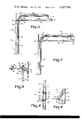
- FIG. 1 is a perspective view of a portion of a garage having a garage door of this invention installed therein;
- FIG. 2 is a rear elevation view of the garage door of FIG. 1, with portions thereof broken away;
- FIG. 3 is a horizontal section taken on the line 3-3 of FIG. 2, with portions thereof broken away;
- FIG. 4 is a horizontal section taken on the line 4-4 of FIG. 2, with portions thereof broken away;
- FIG. 5 is a fragmented vertical section taken on the line 5-5 of FIG. 1;
- FIG. 6 is an enlarged fragmented vertical section taken on the line 6-6 of FIG. 3;
- FIG. 7 is a fragmented vertical section of the garage door similar to FIG. 5, but showing the door in an open position;
- FIG. 8 is an enlarged fragmented vertical section taken on the line 88 of FIG. 1;
- FIG. 9 is an enlarged fragmented vertical section taken on the line 9-9 of FIG. I, and showing one of the ventilators in an open position.
- a garage door 10 of this invention is shown in FIG. I installed in a garage building 12, and generally comprises four rectangular interconnected door panels 14 having their lengths extending horizontally to cover a relatively large garage door opening 16 in a front wall 17 of the garage.
- one of the panels 14 conveniently has a door handle 18 mounted on both the outside and the inside faces thereof to facilitate opening and closing of the door, and if desired, said handle can include conventional locking apparatus (not shown) for selectively locking and unlocking the door.
- the garage door is for use with a garage building having a ceiling 30, as shown in FIG. 2, suspended from the roof of the garage.
- the ceiling 30 is suspended from the garage roofin any conventional convenient manner to provide a substantially open and unobstructed pocket 31 over the ceiling for mounting of the garage door overhead operating apparatus to be hereinafter described, and for reception of the entire garage door over the ceiling.
- the manner of suspending the ceiling can be, for example, tacking of ceiling panels on the underside of overhead ceiling joists, or any other structure to provide the pocket 31.
- the ceiling suspension apparatus is not shown in the drawings for purposes of clarity.
- the rectangular door panels 14 are formed from wood, plastic, or other conventional garage door materials.
- the panels are hingedly interconnected at adjacent longitudinal edges in a stacked relation by rows of hinges 20 mounted as by screws 22 on the inside face of the door 10.
- Each pair of adjacent panels 14 has a pair of the hinges 20 located adjacent the opposed left and right ends thereof, and modified to carry a spindle 24 which extends horizontally outwardly from the panels.
- a roller 26 is rotatably mounted on each of the spindles 24, and said rollers are guidably received in garage door tracks 28 at the opposed jambs of the door opening 16.
- each of the two door tracks 28 has a generally U-shaped cross section to receive and contain the rollers 26 on the door panels and to permit relatively free rotation of the rollers therein.
- the tracks are each generally L-shaped along their lengths, and have a vertically extending portion fixed by conventional construction techniques at each jamb of the door opening 16.
- the tracks each extend upwardly from the top of the door opening 16 inside the garage to a position spaced above the garage ceiling 30 and within the pocket 31.
- the tracks then curve rearwardly and extend horizontally above the ceiling away from the garage door opening 16.
- the horizontal portion of each track 28 is firmly supported in position by a bracket 32 at the rearmost end of the track and which is anchored to the ceiling joists (not shown) of the garage, or like supporting structure.
- the tracks are each provided with a continuous longitudinal slot 34 facing the opposing track and having a width slightly greater than the diameter of the spindles 24 to permit the rollers 26 on the door panels to be received in and guided along the tracks for substantially the entire length of said tracks.
- the vertical extending portions of the tracks 28 are spaced inwardly from the front face of the garage building by a vertical spacer board 36, and all but the slotted surface of each track vertical portion is hidden from view by vertically extending cover panels 38.
- cover panels 38 and the spacer boards 36 overlap the ends of the horizontal door panels 14 to cover the short gap 40 between ends of the door panels 14 and the rollers 26 and thereby provide a relatively tight weather seal for the garage. Further, if desired, the
- tracks 28 can each be formed from telescoping sections to allow their vertical and horizontal lengths to be selected according to the dimensions of any given garage building.
- a rectangularly shaped passage 44 is formed in the garage ceiling adjacent the garage opening 16.
- the passage has a front to rear width governed by parameters to be hereinafter described.
- a trap door 42 is shaped to substantially close the passage 44 and is supported in said closed position on a ledge provided by trim strips 46 mounted on the underside of the garage ceiling 30 and bordering three sides of the passage 44.
- the edge of the passage 44 adjacent the front wall 17 of the garage is bordered as shown in FIG. 5 by an upper spacer board 45 which serves to define the upper extent of the garage door opening 16 and to provide a supportive ledge for the front edge of the trap door 42 when said door 42 is in a closed position.
- the trap door 42 has a pair of guide plates 48 fastened as by screws 50 to its upper surface at its opposed ends adjacent the tracks 28.
- Each guide plate 48 has a finger 52 extending outwardly from the end of the trap door and received through the slot 34 of the adjacent track.
- the fingers 52 of the guide plates 48 are thus arranged in a position vertically above the underlying spindles 24 and rollers 26 which are also received in the tracks 28.
- the trap door 42 has a rod 54 extending horizontally across the top thereof and solidly fixed in position by brackets 56 mounted by the screws 50 to the guide plates 48.
- a center support plate 49 having a bracket 51 is also provided to help support the rod 54.
- the ends of the rod 54 extend outwardly from the ends of the trap door in front of the guide plate fingers 52, and are rotatably received as shown best in FIG. 6 in the eyes of a pair of eye brackets 58.
- Said eye brackets 58 are fastened by screws 60 to the inside face of the uppermost door panel 14. As shown, each eye bracket 58 extends vertically along the inside face of the upper door panel 14, and then curves over the top of said panel 14 and extends vertically again for reception of the rod 54.
- Said rod terminates short of the adjacent tracks 28, as shown in FIG. 2, to avoid interference therewith.
- This thereby hingedly connects the trap door 42 to the upper door panel 14 with an axis of rotation about the axis of the rod 54.
- the eye brackets 58 are mounted laterally outwardly from the ends of trap door to eliminate the necessity of a sizable gap between the upper door panel 14 and said trap door.
- the upper edge of said door panel 14 is conveniently rounded to permit rotation of said panel with respect to the trap door through at least several degrees of angular rotation.
- a torsion bar 62 is mounted within the pocket 31 above the garage ceiling 30 near the rearmost ends of the tracks 28.
- the torsion bar 62 has each of its ends rotatably received in at individual housing 64, each of which is solidly secured to the sides of the garage building, or alternatively to the garage ceiling joists or the like.
- the torsion bar 62 is rotationally spring-loaded and has the ends of a pair of flexible cables 66 fixed thereto.
- the cables 66 are each wound several turns about the torsion bar and each extends forwardly above the garage ceiling for connection to an eye bolt 68 mounted on the trap door 42.
- the torsion bar serves to impart a rearwardly directed force on the trap door 42 and also on the underlying door panels 14 to assist in the opening of the garage door. However, the torsion bar forces are not so strong as to operate' thegarage door without manual assistance.
- the garage door opening 16 is closed when the interconnected door panels 14 are in a vertically extending position within the vertical portions of the tracks 28.In this position; the trap door 42 is in a horizontallyextending position closing the passage 44 in the-garage ceiling 30.
- the underside of the garage ceiling is, substantially undistu-rbed-with no garage-door operating .apparatus suspended therefrom or viewable.
- the underside of the trap door 42 can be formed from the same m-ater-ial as the garage ceiling to further enhance the appearance of the garage'interior. .1
- Thegarage door is moved toan joverhead open position by lifting upwardly-on: one of the door handles 18. Thispushes-the interconnecteddoor.panels 14 upwardly, along the opposed tracks .28.- Suchupward movement also pushes upwardly on thettrap door 42 .to also move the trap door out of the passage 44 and along the tracks 28 as guided by the guide plate fingers 52.
- the trap door 42 and the door panels. 14 each follow along the tracks to a. p osition within the pocket-3.1 spaced above the garage ceiling 30 and then travel rearwardly along thehorizontal portions of the tracks to a fully open position as shown in FIG. 7.
- the garage door panels, 1 4, andthe trap door 42 are within the pocket 31 above the garage ceiling 30 where they are substantially hidden from view. Again, the garage ceiling is substantially undisturbed to both enhance the appearance of the garage and to increase its utility.
- the garage door is moved from the fully open position back to a closed position by pulling downwardly on the lower door panel 14 which will be adjacent the passage 44 in the garage ceiling. This causes the interconnected door panels 14 and the trap door 42 to follow back along the tracks 28 to their original closed positions. A cord (not shown) or the like can be fastened to the lower door panel for pulling downwardly thereon. When in their original closed positions, the door panels 14 again close the garage door opening 16 and the trap door 42 is disposed flush with the closes the ceiling passage 44.
- FIGS. 1 and 2 two of the panels 14 of the garage door are provided with horizontally aligned rectangular openings 70.
- Each opening 70 is covered by a screen 72 permanently affixed by trim strips 74 to the outside face of the door as shown in FIGS. 8 and 9.
- a ventilator unit 76 is mounted by a pair of hinges 78 on the inside face of the panels 14 adjacent each of the openings 70, and is swingable on said hinges 78 between a position closing said adjacent opening and an open position to allow air flow through the adjacent opening into or out of the garage.
- Each ventilator unit 76 comprises a generally rectangular frame 80 shaped for relatively snug reception into the adjacent opening, and has a knob 83 on the inside thereof for opening and closing said unit.
- Each frame has a conventional spring-dentent ball 82 at the bottom thereof for reception into a mating recess 84 in the door panel 14 to releasably retain the ventilator unit in a closed position.
- the frame 80 has an opening 85 therethrough covered by a sheet of covering material 86 which is held in place by trim 88.
- the covering material can be formed from almost any convenient non-ventilating material, such as wood panels or panes of window glass. In the embodiment of the invention illustrated, the covering material in the upper row of in the lower'rowcomprises opague panels.
- the hinges 78 of the ventilator units 76 can be of the type which swing relatively freely or they can be of a stiffer variety which by themselves retain and support theirrespective ventilator 'units in the desired open position. With the former type of hinge, support is required to maintain the ventilator units in an open positiomand thissupport is conveniently provided with knife braces 90 as shown in FIG. 9.
- Each knife brace 90 comprises a length of a relatively thin material such as metal pivoted about a pin 92near the bottom of one sideof each ventilator unit frame 80.
- the knife brace is easily movable from its inoperative dotted line position .to :its fullJine position engaging the inside face of the garage door panel 14 to retain theventilator unit in the desired open position. In this manner, the series of ventilator units can be opened or closed as needed to provide any desired amount of ventilation of the garage.'- 1:: 1 I
- the size and shape of the trap door 42 and the spacingof the horizontal portions of the tracks 28 can be conveniently chosen to allow the garage door 10 to be moved from its closed position to its full open, hidden position while any or all of the ventilator units 76 are open. For example, the'width of the. trap door 42, and
- the door panels 14 are quickly and easily movable between open and closed positions from either the inside or the outside of the garage door regardless of the positions of the ventilator units.
- a garage door assembly for a garage having a garage opening in one wall and a ceiling comprising a plurality of panels hingedly interconnected at adjacent edges one on top of the other; first guide means mounted on said interconnected panels at opposed ends thereof; a pair of stationary generally L-shaped tracks each extending vertically along one side of the garage opening through a passage formed in the garage ceiling to a position above the ceiling and then horizontally away from the garage opening, said guide means on said panels being received in said pair of tracks to allow guidable movement of said panels along said tracks between a vertically extending position closing the garage opening and a horizontally extending position above the garage ceiling; a trap door hingedly connected to one of said panels and disposed to substantially close the passage in the ceiling when said panels are in a closed position; and second guide means mounted on said trap door and received in said tracks whereby said trap door is lifted by said panels upwardly out of the passage along said tracks when said panels are moved from a closed position to a open position.
- each of said venting means comprises a frame hingedly connected to the inside of the garage door adjacent one of said holes, said frame having means mounted thereon for supporting said frame in an open position.
- each of said venting means comprises a frame hingedly connected to the inside of the garage door adjacent one of said holes, said frame having means thereon for locking said frame in a closed position.
- venting means include a sheet of transparent material to permit light to pass therethrough and through the adjacent panel hole when said venting means is in a closed position.
- a garage door assembly for a garage having a garage opening in one wall thereof and a ceiling comprising a plurality of panels hingedly interconnected at adjacent edges one on top of the other, selected ones of said panels having holes formed therethrough; venting means mounted on said preselected panels; a trap door hingedly interconnected to one of said panels; guide means mounted on said trap door and said panels at opposed ends thereof; and a pair of stationary generally L-shaped tracks each extending vertically along one side of the garage opening through a passage formed in the garage ceiling to a position above the ceiling and then horizontally away from the garage opening, said guide means on said trap door and said panels being received in said tracks to allow guidable movement of said trap door and panels between a closed position with said panels extending vertically to close the garage opening and said trap door extending horizontally to substantially close the passage in the garage ceiling and an open position with said trap door and panels extend ing generally horizontally above the garage ceiling.
Landscapes
- Engineering & Computer Science (AREA)
- Mechanical Engineering (AREA)
- Building Environments (AREA)
Abstract
An overhead garage door having hinged horizontal door panels with rollers at opposed ends thereof. The rollers are received in tracks which extend vertically along the sides of the door opening through a passage in the garage ceiling and then horizontally away from the door opening. A trap door connected to said panels has guide means received in the tracks and substantially closes the ceiling passage when the door panels are closed. The panels are together movable upwardly along the tracks to lift the trap door from the ceiling passage and then horizontally rearwardly to a fully open position hidden above the ceiling. The door panels are provided with a series of holes covered by permanently mounted screens. A ventilator is hingedly mounted adjacent each panel hole and is operable from the inside of the door to selectively open or close said holes.
Description
United States Patent [191 Anderson et a1.
[ Dec. 23, 1975 OVERHEAD GARAGE DOOR [76] Inventors: Wilbur R. Anderson; Lydia H.
Anderson, both of 2405 Nichol Ave., Anderson, Ind. 46011 22 Filed: Jan. 2, 1975 21 Appl. No.: 538,184
Related US. Application Data [63] Continuation-impart of Ser. No. 379,220, July 16,
1973, abandoned.
[52] US. Cl. ..-l60/37; 160/116; 160/118;
160/180; 160/201 [51] Int. Cl. E05D 15/24; E05D 15/38 [58] Field of Search 160/113, 116, 201, 209,
[56] References Cited 3,021,896 2/1962 Buono et a1. 160/113 3,103,967 9/1963 Gaschen 160/113 3,178,776 4/1965 Stansberry 160/201 X Primary Examiner-Philip C. Kannan Attorney, Agent, or Firm-Trask, Jenkins & Hanley [57] ABSTRACT An overhead garage door having hinged horizontal door panels with rollers at opposed ends thereof. The rollers are received in tracks which extend vertically along the sides of the door opening through a passage in the garage ceiling and then horizontally away from the door opening. A trap door connected to said panels has guide means received in the tracks and substantially closes the ceiling passage when the door panels are closed. The panels are together movable upwardly along the tracks to lift the trap door from the ceiling passage and then horizontally rearwardly to a fully open position hidden above the ceiling.
The door panels are provided with a series of holes covered by permanently mounted screens. A ventilator is hingedly mounted adjacent each panel hole and is operable from the inside of the door to selectively open or close said holes.
10 Claims, 9 Drawing Figures 4g as 45 K US. Patent Dec. 23, 1975 Sheet 1 of3 3,927,709
OVERHEAD GARAGE DOOR BACKGROUND OF THE INVENTION This application is a continuation-in-part application of, our co-pending application Ser. No. 379,220, filed July- 16, 1973, now abandoned.
This invention relates to garage doors, and more specifically, to an overhead garage door which is quickly and easily movable'between a closed position and an overhead open position hidden from view above the garage ceiling.
' Overhead garage doors are well known in the prior art, and typically comprise a series of hingedly interconnected horizontal door panels. The panels have rollers or 'the like at opposite ends for reception in tracks at.the opposed jambs ofthe door. The tracks extend vertically along the sides of the door and then extend horizontally rearwardly.- The horizontal portions of the tracks, however, are normally suspended from about six inches to one foot below the garage ceiling and have coiled springs attached thereto to assist lifting of the door. This suspended track'and spring apparatus serves to make the inside of the garage unsightly and to limit use of the garage as a room. For example, because the tracks and springs hang below the garage ceiling, they severelyrestrict the-effective ,height of the garage and thereby limit use of the garage as a utility room, game room, or workshop, etc. This restriction on the availability of the garage as an extra room ,is especially undersirable in many modern family dwellings, such as those without basements, wherein maximum use of interior space is a necessity.
As garages are increasingly used for purposes other than storage of automobiles or other items, it is becoming increasingly desirable to provide'apparatus for selectively ventilating the garage. This is especially important to exhaust automobile emissions from the garage before use thereof as for example a game room. Similarly, ventilation of the garage is often desired in hot and humid weather, since the garage is seldom connected to the air conditioning system of a family dwelling. Moreover, in modern dwellings, fuel furnaces are often located in a garage attached to the dwelling, and garage ventilation is often necessary to prevent dangerous buildup of fumes. However, conventional overhead garage doors do not'permit the introduction of fresh air into the garage without partially'opening the door. Such partial opening permits stray dogs, cats, and so forth to readily enter the garage, and also leaves the garage in an unlocked condition. Accordingly, with conventional doors, garage ventilationis often achieved only by the opening of garage windows. These windows are usually inadequate in number and are not located to permit cross-flow ventilationthrough the garage.
Some garage doors have been'developed which have removable window panels for closing openings in the door. See for example US. Pat. NO. 3,178,776. Such doors are not totally satisfactory, however, sincethe windows are usually operable only from the outside of the door, and this subjects the person attempting to close the openings to inclement weather, as during a sudden rainstorm.
It is therefore desirable to providean overhead garage door which is quickly and easily movable between a closed position and an overhead hidden position, which removes the door operating apparatus to a hid- SUMMARY OF THE INVENTION In accordance with the invention, a garage door is provided having a plurality of horizontal door panels hingedly interconnected at adjacent edges one on top of theother. The panels have rollers at the opposed ends thereof which are received in a pair of generally L-shaped tracks extending vertically along each side of the door opening and upwardly through a passage the garage ceiling to above the ceiling, and then rearwardly away from the garage opening. A trap door is hinged to the upper door panel and substantially closes the ceiling passage when the door panels are in a vertical position closing the door opening. The trap door has guide means received in the tracks, and is lifted upwardly along said tracks out of the ceiling passage when said door panels are lifted to permit passage of the door panels therethrough. Further lifting of the door panels causes said panels and the trap door to move together upwardly within the tracks and then rearwardly to a fully open hidden position above the garage ceiling. Reverse movement of the door panels brings said panels back through the ceiling passage to a vertical closed position with the-trap door closing said passage.
At least one of the door panels has a series of holes therethrough covered by screens permanently mounted on the outside of the door. Ventilators are hinged to the inside of the door adjacent each hole and are movable between a position closing the adjacent hole and an open ventilating position.
BRIEF DESCRIPTION OF THE DRAWINGS The accompanying drawings illustrate the invention. In such drawings:
FIG. 1 is a perspective view of a portion of a garage having a garage door of this invention installed therein;
FIG. 2 is a rear elevation view of the garage door of FIG. 1, with portions thereof broken away;
FIG. 3 is a horizontal section taken on the line 3-3 of FIG. 2, with portions thereof broken away;
FIG. 4 is a horizontal section taken on the line 4-4 of FIG. 2, with portions thereof broken away;
FIG. 5 is a fragmented vertical section taken on the line 5-5 of FIG. 1;
FIG. 6 is an enlarged fragmented vertical section taken on the line 6-6 of FIG. 3;
FIG. 7 is a fragmented vertical section of the garage door similar to FIG. 5, but showing the door in an open position;
FIG. 8 is an enlarged fragmented vertical section taken on the line 88 of FIG. 1; and
FIG. 9 is an enlarged fragmented vertical section taken on the line 9-9 of FIG. I, and showing one of the ventilators in an open position.
DETAILED DESCRIPTION OF THE PREFERRED EMBODIMENT Y A garage door 10 of this invention is shown in FIG. I installed in a garage building 12, and generally comprises four rectangular interconnected door panels 14 having their lengths extending horizontally to cover a relatively large garage door opening 16 in a front wall 17 of the garage. As shown, one of the panels 14 conveniently has a door handle 18 mounted on both the outside and the inside faces thereof to facilitate opening and closing of the door, and if desired, said handle can include conventional locking apparatus (not shown) for selectively locking and unlocking the door.
The garage door is for use with a garage building having a ceiling 30, as shown in FIG. 2, suspended from the roof of the garage. The ceiling 30 is suspended from the garage roofin any conventional convenient manner to provide a substantially open and unobstructed pocket 31 over the ceiling for mounting of the garage door overhead operating apparatus to be hereinafter described, and for reception of the entire garage door over the ceiling. The manner of suspending the ceiling can be, for example, tacking of ceiling panels on the underside of overhead ceiling joists, or any other structure to provide the pocket 31. However, the ceiling suspension apparatus is not shown in the drawings for purposes of clarity.
The rectangular door panels 14 are formed from wood, plastic, or other conventional garage door materials. The panels are hingedly interconnected at adjacent longitudinal edges in a stacked relation by rows of hinges 20 mounted as by screws 22 on the inside face of the door 10. Each pair of adjacent panels 14 has a pair of the hinges 20 located adjacent the opposed left and right ends thereof, and modified to carry a spindle 24 which extends horizontally outwardly from the panels. A roller 26 is rotatably mounted on each of the spindles 24, and said rollers are guidably received in garage door tracks 28 at the opposed jambs of the door opening 16.
As shown in FIGS. 2-5, each of the two door tracks 28 has a generally U-shaped cross section to receive and contain the rollers 26 on the door panels and to permit relatively free rotation of the rollers therein. The tracks are each generally L-shaped along their lengths, and have a vertically extending portion fixed by conventional construction techniques at each jamb of the door opening 16. The tracks each extend upwardly from the top of the door opening 16 inside the garage to a position spaced above the garage ceiling 30 and within the pocket 31. The tracks then curve rearwardly and extend horizontally above the ceiling away from the garage door opening 16. The horizontal portion of each track 28 is firmly supported in position by a bracket 32 at the rearmost end of the track and which is anchored to the ceiling joists (not shown) of the garage, or like supporting structure. The tracks are each provided with a continuous longitudinal slot 34 facing the opposing track and having a width slightly greater than the diameter of the spindles 24 to permit the rollers 26 on the door panels to be received in and guided along the tracks for substantially the entire length of said tracks. Conveniently, as shown in FIGS. 3 and 4, the vertical extending portions of the tracks 28 are spaced inwardly from the front face of the garage building by a vertical spacer board 36, and all but the slotted surface of each track vertical portion is hidden from view by vertically extending cover panels 38. These cover panels 38 and the spacer boards 36 overlap the ends of the horizontal door panels 14 to cover the short gap 40 between ends of the door panels 14 and the rollers 26 and thereby provide a relatively tight weather seal for the garage. Further, if desired, the
tracks 28 can each be formed from telescoping sections to allow their vertical and horizontal lengths to be selected according to the dimensions of any given garage building.
A rectangularly shaped passage 44 is formed in the garage ceiling adjacent the garage opening 16. The passage has a front to rear width governed by parameters to be hereinafter described. A trap door 42 is shaped to substantially close the passage 44 and is supported in said closed position on a ledge provided by trim strips 46 mounted on the underside of the garage ceiling 30 and bordering three sides of the passage 44. The edge of the passage 44 adjacent the front wall 17 of the garage is bordered as shown in FIG. 5 by an upper spacer board 45 which serves to define the upper extent of the garage door opening 16 and to provide a supportive ledge for the front edge of the trap door 42 when said door 42 is in a closed position. The trap door 42 has a pair of guide plates 48 fastened as by screws 50 to its upper surface at its opposed ends adjacent the tracks 28. Each guide plate 48 has a finger 52 extending outwardly from the end of the trap door and received through the slot 34 of the adjacent track. The fingers 52 of the guide plates 48 are thus arranged in a position vertically above the underlying spindles 24 and rollers 26 which are also received in the tracks 28.
The trap door 42 has a rod 54 extending horizontally across the top thereof and solidly fixed in position by brackets 56 mounted by the screws 50 to the guide plates 48. A center support plate 49 having a bracket 51 is also provided to help support the rod 54. The ends of the rod 54 extend outwardly from the ends of the trap door in front of the guide plate fingers 52, and are rotatably received as shown best in FIG. 6 in the eyes of a pair of eye brackets 58. Said eye brackets 58 are fastened by screws 60 to the inside face of the uppermost door panel 14. As shown, each eye bracket 58 extends vertically along the inside face of the upper door panel 14, and then curves over the top of said panel 14 and extends vertically again for reception of the rod 54. Said rod terminates short of the adjacent tracks 28, as shown in FIG. 2, to avoid interference therewith. This thereby hingedly connects the trap door 42 to the upper door panel 14 with an axis of rotation about the axis of the rod 54. Because the door panels 14 are slightly wider than the trap door 42, the eye brackets 58 are mounted laterally outwardly from the ends of trap door to eliminate the necessity of a sizable gap between the upper door panel 14 and said trap door. And the upper edge of said door panel 14 is conveniently rounded to permit rotation of said panel with respect to the trap door through at least several degrees of angular rotation.
A torsion bar 62 is mounted within the pocket 31 above the garage ceiling 30 near the rearmost ends of the tracks 28. The torsion bar 62 has each of its ends rotatably received in at individual housing 64, each of which is solidly secured to the sides of the garage building, or alternatively to the garage ceiling joists or the like. The torsion bar 62 is rotationally spring-loaded and has the ends of a pair of flexible cables 66 fixed thereto. The cables 66 are each wound several turns about the torsion bar and each extends forwardly above the garage ceiling for connection to an eye bolt 68 mounted on the trap door 42. The torsion bar serves to impart a rearwardly directed force on the trap door 42 and also on the underlying door panels 14 to assist in the opening of the garage door. However, the torsion bar forces are not so strong as to operate' thegarage door without manual assistance.
The garage door opening 16 is closed when the interconnected door panels 14 are in a vertically extending position within the vertical portions of the tracks 28.In this position; the trap door 42 is in a horizontallyextending position closing the passage 44 in the-garage ceiling 30. When the door is in this closed position, the underside of the garage ceiling is, substantially undistu-rbed-with no garage-door operating .apparatus suspended therefrom or viewable. If desired, the underside of the trap door 42 can be formed from the same m-ater-ial as the garage ceiling to further enhance the appearance of the garage'interior. .1
Thegarage door is moved toan joverhead open position by lifting upwardly-on: one of the door handles 18. Thispushes-the interconnecteddoor.panels 14 upwardly, along the opposed tracks .28.- Suchupward movement also pushes upwardly on thettrap door 42 .to also move the trap door out of the passage 44 and along the tracks 28 as guided by the guide plate fingers 52. The trap door 42 and the door panels. 14 each follow along the tracks to a. p osition within the pocket-3.1 spaced above the garage ceiling 30 and then travel rearwardly along thehorizontal portions of the tracks to a fully open position as shown in FIG. 7. As shown, the garage door panels, 1 4, andthe trap door 42 are within the pocket 31 above the garage ceiling 30 where they are substantially hidden from view. Again, the garage ceiling is substantially undisturbed to both enhance the appearance of the garage and to increase its utility.
The garage door is moved from the fully open position back to a closed position by pulling downwardly on the lower door panel 14 which will be adjacent the passage 44 in the garage ceiling. This causes the interconnected door panels 14 and the trap door 42 to follow back along the tracks 28 to their original closed positions. A cord (not shown) or the like can be fastened to the lower door panel for pulling downwardly thereon. When in their original closed positions, the door panels 14 again close the garage door opening 16 and the trap door 42 is disposed flush with the closes the ceiling passage 44.
As shown in FIGS. 1 and 2, two of the panels 14 of the garage door are provided with horizontally aligned rectangular openings 70. Each opening 70 is covered by a screen 72 permanently affixed by trim strips 74 to the outside face of the door as shown in FIGS. 8 and 9. A ventilator unit 76 is mounted by a pair of hinges 78 on the inside face of the panels 14 adjacent each of the openings 70, and is swingable on said hinges 78 between a position closing said adjacent opening and an open position to allow air flow through the adjacent opening into or out of the garage. Each ventilator unit 76 comprises a generally rectangular frame 80 shaped for relatively snug reception into the adjacent opening, and has a knob 83 on the inside thereof for opening and closing said unit. Each frame has a conventional spring-dentent ball 82 at the bottom thereof for reception into a mating recess 84 in the door panel 14 to releasably retain the ventilator unit in a closed position. The frame 80 has an opening 85 therethrough covered by a sheet of covering material 86 which is held in place by trim 88. The covering material can be formed from almost any convenient non-ventilating material, such as wood panels or panes of window glass. In the embodiment of the invention illustrated, the covering material in the upper row of in the lower'rowcomprises opague panels.
The hinges 78 of the ventilator units 76can be of the type which swing relatively freely or they can be of a stiffer variety which by themselves retain and support theirrespective ventilator 'units in the desired open position. With the former type of hinge, support is required to maintain the ventilator units in an open positiomand thissupport is conveniently provided with knife braces 90 as shown in FIG. 9. Each knife brace 90 comprises a length of a relatively thin material such as metal pivoted about a pin 92near the bottom of one sideof each ventilator unit frame 80. The knife brace is easily movable from its inoperative dotted line position .to :its fullJine position engaging the inside face of the garage door panel 14 to retain theventilator unit in the desired open position. In this manner, the series of ventilator units can be opened or closed as needed to provide any desired amount of ventilation of the garage.'- 1:: 1 I
The size and shape of the trap door 42 and the spacingof the horizontal portions of the tracks 28 can be conveniently chosen to allow the garage door 10 to be moved from its closed position to its full open, hidden position while any or all of the ventilator units 76 are open. For example, the'width of the. trap door 42, and
thereby also the.ceiling passage 44, must be greater than. the distance the ventilator units 76 extend rearwardly from their respective door panels 14 when said units are open. Similarly, the spacing of the horizontal portions of the tracks 28 above the garage ceiling 30 must be greater than the distance the units 76 extend rearwardly from their door panels when said units are open. With this construction, the door panels 14 are quickly and easily movable between open and closed positions from either the inside or the outside of the garage door regardless of the positions of the ventilator units.
We claim:
1. A garage door assembly for a garage having a garage opening in one wall and a ceiling, comprising a plurality of panels hingedly interconnected at adjacent edges one on top of the other; first guide means mounted on said interconnected panels at opposed ends thereof; a pair of stationary generally L-shaped tracks each extending vertically along one side of the garage opening through a passage formed in the garage ceiling to a position above the ceiling and then horizontally away from the garage opening, said guide means on said panels being received in said pair of tracks to allow guidable movement of said panels along said tracks between a vertically extending position closing the garage opening and a horizontally extending position above the garage ceiling; a trap door hingedly connected to one of said panels and disposed to substantially close the passage in the ceiling when said panels are in a closed position; and second guide means mounted on said trap door and received in said tracks whereby said trap door is lifted by said panels upwardly out of the passage along said tracks when said panels are moved from a closed position to a open position.
2. A garage door assembly as set forth in claim 1 wherein said first guide means comprises a plurality of rollers at each end of said interconnected panels.
3. A garage door assembly as set forth in claim 1 with the addition of spring means mounted above the ceiling and interconnected to said trap door by flexible con- 7 necting means, said spring means serving to assist movement of the trap door and panels along the tracks between a closed position and an open position.
4. A garage door assembly as set forth in claim 1 wherein selected ones of said panels have holes formed therein, and with the addition of venting means mounted on said selected panels and operable from the inside of the garage to selectively open and close said holes.
5. A garage door assembly as set forth in claim 4 wherein each of said venting means comprises a frame hingedly connected to the inside of the garage door adjacent one of said holes, said frame having means mounted thereon for supporting said frame in an open position.
6. A garage door assembly as set forth in claim 4 wherein each of said holes has a screen mounted thereover.
7. A garage door assembly as set forth in claim 4 wherein each of said venting means comprises a frame hingedly connected to the inside of the garage door adjacent one of said holes, said frame having means thereon for locking said frame in a closed position.
8. A garage door assembly as set forth in claim 7 where selected ones of said venting means include a sheet of transparent material to permit light to pass therethrough and through the adjacent panel hole when said venting means is in a closed position.
9. A garage door assembly for a garage having a garage opening in one wall thereof and a ceiling, comprising a plurality of panels hingedly interconnected at adjacent edges one on top of the other, selected ones of said panels having holes formed therethrough; venting means mounted on said preselected panels; a trap door hingedly interconnected to one of said panels; guide means mounted on said trap door and said panels at opposed ends thereof; and a pair of stationary generally L-shaped tracks each extending vertically along one side of the garage opening through a passage formed in the garage ceiling to a position above the ceiling and then horizontally away from the garage opening, said guide means on said trap door and said panels being received in said tracks to allow guidable movement of said trap door and panels between a closed position with said panels extending vertically to close the garage opening and said trap door extending horizontally to substantially close the passage in the garage ceiling and an open position with said trap door and panels extend ing generally horizontally above the garage ceiling.
10. A garage door assembly as set forth in claim 8 wherein said venting means are each hingedly connected to the inside of the selected panels and swinga'ble between an open and closed position, said passage in the garage ceiling extending rearwardly from the garage opening and said tracks extending vertically above the garage ceiling for sufficient distances to allow guidable movement of the trap door and panels between open and closed positions when said venting means are in an open position.
Claims (10)
1. A garage door assembly for a garage having a garage opening in one wall and a ceiling, comprising a plurality of panels hingedly interconnected at adjacent edges one on top of the other; first guide means mounted on said interconnected panels at opposed ends thereof; a pair of stationary generally L-shaped tracks each extending vertically along one side of the garage opening through a passage formed in the garage ceiling to a position above the ceiling and then horizontally away from the garage opening, said guide means on said panels being received in said pair of tracks to allow guidable movement of said panels along said tracks between a vertically extending position closing the garage opening and a horizontally extending position above the garage ceiling; a trap door hingedly connected to one of said panels and disposed to substantially close the passage in the ceiling when said panels are in a closed position; and second guide means mounted on said trap door and received in said tracks whereby said trap door is lifted by said panels upwardly out of the passage along said tracks when said panels are moved from a closed position to a open position.
2. A garage door assembly as set forth in claim 1 wherein said first guide means comprises a plurality of rollers at each end of said interconnected panels.
3. A garage door assembly as set forth in claim 1 with the addition of spring means mounted above the ceiling and interconnected to said trap door by flexible connecting means, said spring means serving to assist movement of the trap door and panels along the tracks between a closed position and an open position.
4. A garage door assembly as set forth in claim 1 wherein selected ones of said panels have holes formed therein, and with the addition of venting means mounted on said selected panels and operable from the inside of the garage to selectively open and close said holes.
5. A garage door assembly as set forth in claim 4 wherein each of said venting means comprises a frame hingedly connected to the inside of the garage door adjacent one of said holes, said frame having means mounted thereon for supporting said frame in an open position.
6. A garage door assembly as set forth in claim 4 wherein each of said holes has a screen mounted thereover.
7. A garage door assembly as set forth in claim 4 wherein each of said venting means comprises a frame hingedly connected to the inside of the garage door adjacent one of said holes, said frame having means thereon for locking said frame in a closed position.
8. A garage door assembly as set forth in claim 7 where selected ones of said venting means include a sheet of transparent material to permit light to pass therethrough and through the adjacent panel hole when said venting means is in a closed position.
9. A garage door assembly for a garage having a garage opening in one wall thereof and a ceiling, comprising a plurality of panels hingedly interconNected at adjacent edges one on top of the other, selected ones of said panels having holes formed therethrough; venting means mounted on said preselected panels; a trap door hingedly interconnected to one of said panels; guide means mounted on said trap door and said panels at opposed ends thereof; and a pair of stationary generally L-shaped tracks each extending vertically along one side of the garage opening through a passage formed in the garage ceiling to a position above the ceiling and then horizontally away from the garage opening, said guide means on said trap door and said panels being received in said tracks to allow guidable movement of said trap door and panels between a closed position with said panels extending vertically to close the garage opening and said trap door extending horizontally to substantially close the passage in the garage ceiling and an open position with said trap door and panels extending generally horizontally above the garage ceiling.
10. A garage door assembly as set forth in claim 8 wherein said venting means are each hingedly connected to the inside of the selected panels and swingable between an open and closed position, said passage in the garage ceiling extending rearwardly from the garage opening and said tracks extending vertically above the garage ceiling for sufficient distances to allow guidable movement of the trap door and panels between open and closed positions when said venting means are in an open position.
Priority Applications (1)
| Application Number | Priority Date | Filing Date | Title |
|---|---|---|---|
| US538184A US3927709A (en) | 1973-07-16 | 1975-01-02 | Overhead garage door |
Applications Claiming Priority (2)
| Application Number | Priority Date | Filing Date | Title |
|---|---|---|---|
| US37922073A | 1973-07-16 | 1973-07-16 | |
| US538184A US3927709A (en) | 1973-07-16 | 1975-01-02 | Overhead garage door |
Publications (1)
| Publication Number | Publication Date |
|---|---|
| US3927709A true US3927709A (en) | 1975-12-23 |
Family
ID=27008518
Family Applications (1)
| Application Number | Title | Priority Date | Filing Date |
|---|---|---|---|
| US538184A Expired - Lifetime US3927709A (en) | 1973-07-16 | 1975-01-02 | Overhead garage door |
Country Status (1)
| Country | Link |
|---|---|
| US (1) | US3927709A (en) |
Cited By (33)
| Publication number | Priority date | Publication date | Assignee | Title |
|---|---|---|---|---|
| US4141403A (en) * | 1978-06-16 | 1979-02-27 | Church Rocco L | Garage-patio door |
| US4375876A (en) * | 1981-06-04 | 1983-03-08 | The Boeing Company | Overhead sliding door and foldable cabin panel assembly for an airplane |
| US4378043A (en) * | 1981-05-26 | 1983-03-29 | Sorenson Robert V | Pivoting screen panel for sectional garage door |
| WO1984001140A1 (en) * | 1982-09-13 | 1984-03-29 | Boeing Co | Overhead sliding door and foldable cabin panel assembly for an airplane |
| US4653566A (en) * | 1985-10-23 | 1987-03-31 | Miale Michael R | Garage door screen system |
| US5425409A (en) * | 1993-12-17 | 1995-06-20 | Guia; Armando E. | Door mounting system |
| US5673740A (en) * | 1994-10-14 | 1997-10-07 | Kap-Il Park | Shutter equipment for a building |
| WO1999035360A1 (en) * | 1998-01-06 | 1999-07-15 | Mckeon Rolling Steel Door Company, Inc. | A rolling fire door including a plurality of substantially unitary pivotal doors |
| US6386969B1 (en) | 2001-09-21 | 2002-05-14 | O'brien Robert D. | Garage ventilation system |
| US20030082008A1 (en) * | 1997-07-10 | 2003-05-01 | Sprengle E. Carl | Flood gate for door |
| US6715527B2 (en) * | 2001-12-11 | 2004-04-06 | Raymond V. Ardoin | Ventilation apparatus for garages |
| US20040163776A1 (en) * | 2002-10-11 | 2004-08-26 | Mike Brown | High wind load resistant sectional wood overhead door, assembly, and methods |
| US20060289127A1 (en) * | 2005-06-24 | 2006-12-28 | Darrell Fowler | Garage door having removable vent or glass covers |
| US9163845B1 (en) | 2011-08-10 | 2015-10-20 | D. George Carlozzi | Garage ventilation system |
| US9353569B1 (en) | 2015-04-08 | 2016-05-31 | Smart Vent Products, Inc. | Connectors for a flood vent |
| US9376803B1 (en) | 2015-04-08 | 2016-06-28 | Smart Vent Products, Inc. | Flood vent trigger systems |
| JP2016125215A (en) * | 2014-12-26 | 2016-07-11 | 積水ハウス株式会社 | Residence with garage |
| JP2016153575A (en) * | 2015-02-20 | 2016-08-25 | 積水ハウス株式会社 | Housing with garage |
| US9551153B2 (en) | 2015-04-08 | 2017-01-24 | Smart Vent Products, Inc. | Scupper door systems |
| US9624637B2 (en) | 2015-04-08 | 2017-04-18 | Smart Vent Products, Inc. | Flood vent |
| US9637912B1 (en) | 2015-12-10 | 2017-05-02 | Smart Vent Products, Inc. | Flood vent having a panel |
| US9719249B2 (en) | 2015-12-10 | 2017-08-01 | Smart Vent Products, Inc. | Flood vent having a panel |
| US9758982B2 (en) | 2015-12-10 | 2017-09-12 | Smart Vent Products, Inc. | Flood vent having a panel |
| US20180056988A1 (en) * | 2016-08-23 | 2018-03-01 | Ford Global Technologies, Llc | Vehicle remote starter safety system |
| US10113309B2 (en) | 2015-04-08 | 2018-10-30 | Smart Vent Products, Inc. | Flood vent barrier systems |
| US20190203461A1 (en) * | 2015-12-10 | 2019-07-04 | Smart Vent Products, Inc. | Flood vent having a panel |
| US10385611B2 (en) * | 2015-12-10 | 2019-08-20 | Smart Vent Products, Inc. | Flood vent having a panel |
| US10428567B2 (en) | 2016-10-14 | 2019-10-01 | Cornellcookson, Llc | Multi-panel stacking overhead door |
| US10538304B2 (en) * | 2015-11-10 | 2020-01-21 | Airbus Operations Gmbh | Aircraft door assembly |
| US10597135B2 (en) * | 2015-12-23 | 2020-03-24 | Airbus Operations Sas | Aircraft cell comprising a door opening in rectilinear translation |
| US10975613B2 (en) * | 2016-06-30 | 2021-04-13 | New Heaven And Earth Designs. Llc | Garage door with operable rotating and retractable panels |
| US12366106B1 (en) * | 2024-05-13 | 2025-07-22 | Frederick Shadracks | Foldable ventilated garage door panel |
| US20250354437A1 (en) * | 2024-05-15 | 2025-11-20 | Michael Edward Hoenig | Garage door screen with swinging door |
Citations (10)
| Publication number | Priority date | Publication date | Assignee | Title |
|---|---|---|---|---|
| US148793A (en) * | 1874-03-17 | Improvement in vestibule-doors | ||
| US532483A (en) * | 1895-01-15 | Peter poertner and william romunder | ||
| US843139A (en) * | 1906-10-31 | 1907-02-05 | Samuel Feldman | Ventilating window-sash. |
| US1779062A (en) * | 1928-11-28 | 1930-10-21 | Alfonso Alex C D | Screened window |
| US1889638A (en) * | 1931-01-22 | 1932-11-29 | Fred V Cooper | Door |
| US2453554A (en) * | 1945-05-11 | 1948-11-09 | Thomas John | Overhead door guiding and latching mechanism |
| US2607408A (en) * | 1950-03-22 | 1952-08-19 | Hugh W Bascom | Door |
| US3021896A (en) * | 1959-11-18 | 1962-02-20 | Joseph A Buono | Overhead garage door and screen combination |
| US3103967A (en) * | 1961-07-03 | 1963-09-17 | Leon B Gaschen | Screen door assembly for garages |
| US3178776A (en) * | 1962-03-09 | 1965-04-20 | Robert F Stansberry | Garage door |
-
1975
- 1975-01-02 US US538184A patent/US3927709A/en not_active Expired - Lifetime
Patent Citations (10)
| Publication number | Priority date | Publication date | Assignee | Title |
|---|---|---|---|---|
| US148793A (en) * | 1874-03-17 | Improvement in vestibule-doors | ||
| US532483A (en) * | 1895-01-15 | Peter poertner and william romunder | ||
| US843139A (en) * | 1906-10-31 | 1907-02-05 | Samuel Feldman | Ventilating window-sash. |
| US1779062A (en) * | 1928-11-28 | 1930-10-21 | Alfonso Alex C D | Screened window |
| US1889638A (en) * | 1931-01-22 | 1932-11-29 | Fred V Cooper | Door |
| US2453554A (en) * | 1945-05-11 | 1948-11-09 | Thomas John | Overhead door guiding and latching mechanism |
| US2607408A (en) * | 1950-03-22 | 1952-08-19 | Hugh W Bascom | Door |
| US3021896A (en) * | 1959-11-18 | 1962-02-20 | Joseph A Buono | Overhead garage door and screen combination |
| US3103967A (en) * | 1961-07-03 | 1963-09-17 | Leon B Gaschen | Screen door assembly for garages |
| US3178776A (en) * | 1962-03-09 | 1965-04-20 | Robert F Stansberry | Garage door |
Cited By (49)
| Publication number | Priority date | Publication date | Assignee | Title |
|---|---|---|---|---|
| US4141403A (en) * | 1978-06-16 | 1979-02-27 | Church Rocco L | Garage-patio door |
| US4378043A (en) * | 1981-05-26 | 1983-03-29 | Sorenson Robert V | Pivoting screen panel for sectional garage door |
| US4375876A (en) * | 1981-06-04 | 1983-03-08 | The Boeing Company | Overhead sliding door and foldable cabin panel assembly for an airplane |
| WO1984001140A1 (en) * | 1982-09-13 | 1984-03-29 | Boeing Co | Overhead sliding door and foldable cabin panel assembly for an airplane |
| US4653566A (en) * | 1985-10-23 | 1987-03-31 | Miale Michael R | Garage door screen system |
| US5425409A (en) * | 1993-12-17 | 1995-06-20 | Guia; Armando E. | Door mounting system |
| US5673740A (en) * | 1994-10-14 | 1997-10-07 | Kap-Il Park | Shutter equipment for a building |
| US20030082008A1 (en) * | 1997-07-10 | 2003-05-01 | Sprengle E. Carl | Flood gate for door |
| US6692187B2 (en) * | 1997-07-10 | 2004-02-17 | Smart Vent, Inc. | Flood gate for door |
| WO1999035360A1 (en) * | 1998-01-06 | 1999-07-15 | Mckeon Rolling Steel Door Company, Inc. | A rolling fire door including a plurality of substantially unitary pivotal doors |
| US6386969B1 (en) | 2001-09-21 | 2002-05-14 | O'brien Robert D. | Garage ventilation system |
| US6715527B2 (en) * | 2001-12-11 | 2004-04-06 | Raymond V. Ardoin | Ventilation apparatus for garages |
| US7299853B2 (en) * | 2002-10-11 | 2007-11-27 | Designer Doors, Inc. | High wind load resistant sectional wood overhead door, assembly, and methods |
| US20040163776A1 (en) * | 2002-10-11 | 2004-08-26 | Mike Brown | High wind load resistant sectional wood overhead door, assembly, and methods |
| US20080083166A1 (en) * | 2002-10-11 | 2008-04-10 | Designer Doors Inc. | High wind load resistant sectional wood overhead door, assembly, and methods |
| US7484286B2 (en) * | 2005-06-24 | 2009-02-03 | Darrell Fowler | Garage door having removable vent or glass covers |
| US20060289127A1 (en) * | 2005-06-24 | 2006-12-28 | Darrell Fowler | Garage door having removable vent or glass covers |
| US9163845B1 (en) | 2011-08-10 | 2015-10-20 | D. George Carlozzi | Garage ventilation system |
| JP2016125215A (en) * | 2014-12-26 | 2016-07-11 | 積水ハウス株式会社 | Residence with garage |
| JP2016153575A (en) * | 2015-02-20 | 2016-08-25 | 積水ハウス株式会社 | Housing with garage |
| US9376803B1 (en) | 2015-04-08 | 2016-06-28 | Smart Vent Products, Inc. | Flood vent trigger systems |
| US9353569B1 (en) | 2015-04-08 | 2016-05-31 | Smart Vent Products, Inc. | Connectors for a flood vent |
| US9551153B2 (en) | 2015-04-08 | 2017-01-24 | Smart Vent Products, Inc. | Scupper door systems |
| US9624637B2 (en) | 2015-04-08 | 2017-04-18 | Smart Vent Products, Inc. | Flood vent |
| US10113286B2 (en) | 2015-04-08 | 2018-10-30 | Smart Vent Products, Inc. | Flood vent |
| US9670717B2 (en) | 2015-04-08 | 2017-06-06 | Smart Vent Products, Inc. | Flood vent trigger systems |
| US10619319B2 (en) | 2015-04-08 | 2020-04-14 | Smart Vent Products, Inc. | Flood vent |
| US10113309B2 (en) | 2015-04-08 | 2018-10-30 | Smart Vent Products, Inc. | Flood vent barrier systems |
| US10538304B2 (en) * | 2015-11-10 | 2020-01-21 | Airbus Operations Gmbh | Aircraft door assembly |
| US9637912B1 (en) | 2015-12-10 | 2017-05-02 | Smart Vent Products, Inc. | Flood vent having a panel |
| US10584510B2 (en) | 2015-12-10 | 2020-03-10 | Smart Vent Products, Inc. | Flood vent having a panel |
| US9909302B2 (en) | 2015-12-10 | 2018-03-06 | Smart Vent Products, Inc. | Flood vent having a panel |
| US12215495B2 (en) | 2015-12-10 | 2025-02-04 | Smart Vent Products Llc | Flood vent having a panel |
| US10161156B2 (en) | 2015-12-10 | 2018-12-25 | Smart Vent Products, Inc. | Flood vent having a panel |
| US20190203461A1 (en) * | 2015-12-10 | 2019-07-04 | Smart Vent Products, Inc. | Flood vent having a panel |
| US10385611B2 (en) * | 2015-12-10 | 2019-08-20 | Smart Vent Products, Inc. | Flood vent having a panel |
| US11021886B2 (en) | 2015-12-10 | 2021-06-01 | Smart Vent Products, Inc. | Flood vent having a panel |
| US9758982B2 (en) | 2015-12-10 | 2017-09-12 | Smart Vent Products, Inc. | Flood vent having a panel |
| US10017937B2 (en) | 2015-12-10 | 2018-07-10 | Smart Vent Products, Inc. | Flood vent having a panel |
| US11002006B2 (en) * | 2015-12-10 | 2021-05-11 | Smart Vent Products, Inc. | Flood vent having a panel |
| US9719249B2 (en) | 2015-12-10 | 2017-08-01 | Smart Vent Products, Inc. | Flood vent having a panel |
| US10619345B2 (en) * | 2015-12-10 | 2020-04-14 | Smart Vent Products, Inc. | Flood vent having a panel |
| US20200240134A1 (en) * | 2015-12-10 | 2020-07-30 | Smart Vent Products, Inc. | Flood vent having a panel |
| US10597135B2 (en) * | 2015-12-23 | 2020-03-24 | Airbus Operations Sas | Aircraft cell comprising a door opening in rectilinear translation |
| US10975613B2 (en) * | 2016-06-30 | 2021-04-13 | New Heaven And Earth Designs. Llc | Garage door with operable rotating and retractable panels |
| US20180056988A1 (en) * | 2016-08-23 | 2018-03-01 | Ford Global Technologies, Llc | Vehicle remote starter safety system |
| US10428567B2 (en) | 2016-10-14 | 2019-10-01 | Cornellcookson, Llc | Multi-panel stacking overhead door |
| US12366106B1 (en) * | 2024-05-13 | 2025-07-22 | Frederick Shadracks | Foldable ventilated garage door panel |
| US20250354437A1 (en) * | 2024-05-15 | 2025-11-20 | Michael Edward Hoenig | Garage door screen with swinging door |
Similar Documents
| Publication | Publication Date | Title |
|---|---|---|
| US3927709A (en) | Overhead garage door | |
| US4141403A (en) | Garage-patio door | |
| US4653566A (en) | Garage door screen system | |
| US4378043A (en) | Pivoting screen panel for sectional garage door | |
| US6227278B1 (en) | Swing door and roll-up door with plural door facade | |
| US4770087A (en) | Garage door ventilator | |
| US3811224A (en) | Pet door panel | |
| US5050660A (en) | Screen door for large door opening | |
| US4574860A (en) | Adjustable storm garage door | |
| US4094099A (en) | Screen door assembly | |
| US3938577A (en) | Door structure employing an auxiliary door | |
| US6213187B1 (en) | Replacement window with shutter | |
| US20090320377A1 (en) | Casement Window | |
| US6070637A (en) | Horizontally openable window | |
| US2320268A (en) | Ventilator | |
| US3126944A (en) | Overhead self-storing garage screen door | |
| US4057937A (en) | Window sash assembly | |
| US20060137832A1 (en) | Overhead track screen door for garages | |
| US6668899B1 (en) | Laterally moving supports for horizontal blinds | |
| US3796015A (en) | Car pod | |
| EP0308105B1 (en) | A balcony window and door arrangement in an inclined roof | |
| US4330021A (en) | Convenient draft-free safety window | |
| US2513278A (en) | Combined storm window awning and screen | |
| JPH0552189U (en) | Lattice body with opening and closing function | |
| JP2000303751A (en) | Vertical directional collapsible rain door |