US3752428A - Gutter hanger assembly - Google Patents
Gutter hanger assembly Download PDFInfo
- Publication number
- US3752428A US3752428A US00151807A US3752428DA US3752428A US 3752428 A US3752428 A US 3752428A US 00151807 A US00151807 A US 00151807A US 3752428D A US3752428D A US 3752428DA US 3752428 A US3752428 A US 3752428A
- Authority
- US
- United States
- Prior art keywords
- gutter
- gutter hanger
- body portion
- hanger element
- flange
- Prior art date
- Legal status (The legal status is an assumption and is not a legal conclusion. Google has not performed a legal analysis and makes no representation as to the accuracy of the status listed.)
- Expired - Lifetime
Links
Images


Classifications
-
- E—FIXED CONSTRUCTIONS
- E04—BUILDING
- E04D—ROOF COVERINGS; SKY-LIGHTS; GUTTERS; ROOF-WORKING TOOLS
- E04D13/00—Special arrangements or devices in connection with roof coverings; Protection against birds; Roof drainage ; Sky-lights
- E04D13/04—Roof drainage; Drainage fittings in flat roofs, balconies or the like
- E04D13/064—Gutters
- E04D13/072—Hanging means
- E04D13/0725—Hanging means situated above or inside the gutter
Definitions
- ABSTRACT An adjustable gutter hanger assembly having first and second gutter hanger elements which are adjustably secured to each other and secure a gutter having its innermost vertical wall in spaced outward position with respect to the adjacent fascia or other building surface.
- the 5 5 96 second gutter hanger element may have a reinforcing body portion and an upwardly open rearwardly dis- 5 References Cited posed channel.
- the reinforcing means are preferably T D STATES PATENTS integrally formed hollow ribs.
- the second element has an anchoring portion and a forwardly and downwardly inclined 110,726 5/1940 Australia 248/48.l pp flange which overlies and is closely adjacent to the upwardly open channel of the first element.
- This invention relates to a multipiece gutter hanger assembly and more specifically an adjustable gutter hanger assembly adapted to provide strong retention of the gutter in spaced outward relationship with respect i in a position closely underlying the marginal edges of to the fascia or other building element to which it is secured.
- gutter hanger structures which are adapted to be positioned more closely to the marginal edges of roof structures. Such structures are shown in US. Pat. Nos. 1,855,241, 2,536,704 and 3,416,760.
- One of the principal objections to this form of'structure is that it has fasteners which extend through one or both walls of the gutter element. It, therefore, does not permit relative longitudinal sliding movement between the gutter and hanger or building wall element for thermal expansion and contraction.
- a two-piece hanger structure is shown in US. Pat.
- the present invention has solved the abovedescribed problems by providing a specifically configurated pair of adjustably secured gutter hanger components which are secured to a building wall element or other building component and are integrally reinforced to provide substantial load bearing characteristics under various types of exposures.
- the structures may be firmly anchored at the upper edge of fascia or other building components in order to provide a minimum gap between a marginal roof edge and the gutter.
- the structure provides for free longitudinal sliding movement between a gutter and the multipiece hanger assembly.
- the inner gutter wall is disposed in spaced relationship with respect to the building wall element and is preferably spaced forwardly from the rear leg of the hanger assembly.
- the gutter hanger assembly of this invention has a first gutter hanger element having a body portion, a
- hanger has a generally inwardly open channel portion which engages and secures a downwardly open channel in the outer gutter wall.
- the inner gutter wall has a downwardly open channel which is engaged within the upwardly open rear channel of the second gutter hanger.
- the rear wall is disposed in forwardly spaced relationship with respect to both'the building wall structure and the rear flange of the first gutter hanger element.
- objectionable noise and undesired frictional resistance to longitudinal relative movement between the gutter and the gutter hanger assembly and/or building wall element are eliminated.
- potentially destructive wear between inner or rear gutter walls and the rear flange and/or building wall or fasteners is eliminated.
- the body portion of the first gutter hanger element preferably has a substantially continuous slope between its rearmost portion and its forwardmost portion.
- the upper portion of the downwardly directed flange extends no higher than the plane of the web-like section of the body portion.
- the mouth of the upwardly open channel in the second gutter hanger element is disposed lower than a plane through the weblike portion of the second element. In this fashion the upper portion of the inner gutter wall is positioned in close proximity to the undersurface of the body portion and a more intimate interlocking permanent engagement is obtained.
- the first gutter hanger element has a body portion, a rear flange defining an upwardly open channel and an upwardly directed outer flange.
- a second gutter hanger element has an anchor portion and a downwardly and forwardly directed upper flange emerging from the upper extremity of the anchor portion.
- the second gutter hanger element upper flange is disposed at least in part in overlying position with respect to the first gutter hanger body portion.
- Fastener means which may be integrally formed, secure the two elements together. Integral reinforcing means are provided. Integral anchoring tabs may be formed within the anchor portion for securing the assembly to a building structure.
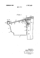
- FIG. 1 is a sectional elevation of a form of gutter assembly contemplated by this invention.
- FIG. 2 is a top plan view of a first gutter hanger component provided by this invention.
- FIG. 3 is an end elevational view of the hanger component shown in FIG. 2.
- FIG. 4 is a detailed illustration of the rear flange structure of the hanger component shown in FIGS. 2 and 3.
- FIG. 5 shows a top plan view of a form of second hanger element contemplated by this invention.
- FIG. 6 is an end elevational view of the hanger component shown in FIG. 5.
- FIG. 7 is a perspective view of a modified form of gutter hanger assembly of this invention.
- FIG. 8 is a sectional view of the modified form of hanger assembly taken through 8-8 of FIG. 7.
- FIG. 9 is a perspective view of another modified form of gutter hanger assembly of this invention.
- FIG. 10 is a cross sectional view of the modified form of hanger assembly shown in FIG. 9 taken through l0-l0.
- a gutter 2 is provided with a base wall 4, an outer wall 6 and an inner wall 8.
- the outer wall has an upper extremity which defines a downwardly open channel 10 having a restricted throat opening effected by flange portion 12.
- the inner gutter wall 8 has an upper extremity which is provided with a reentrant flange 16 which cooperates with wall 8 to define a downwardly open channel 18.
- the gutter hanger assembly has a first gutter hanger element 20 and a second gutter hanger element 24. These elements 20, 24 are adjustably secured to each First gutter hanger element 20 has a body portion 30, a downwardly directed rear flange 34 and an upwardly directed outer flange 36. The upwardly directed outer flange terminates in a reentrant section 36a and defines generally inwardly open channel 38. Flange 36 is in interlocking supporting engagement with the upper portion of outer wall 6 of gutter 2.
- Downwardly directed rear flange 34 is in general surface to surface contact with building wall element 40 at a position closely adjacent the upper surface of the wall immediately underlying the' marginal edge 44 of the roof structure indicated generally by the numeral 46. It will be appreciated that the gutter hanger assembly of this invention may be employed with various forms of roof structures. In another preferred form, the flange 34 would be positioned downwardly with respect to the position shown in FIG. 1 and roof structure 46 would extend farther downwardly and outwardly. This would place marginal edge 44 of the roof shingle and portions of the underlying sheathing board in overlying position with respect to the upwardly open gutter 2.
- Suitable fastening means 48 which in the form shown are screws, are employed to secure the first gutter hanger element 20 to the building wall element 40.
- Fastening means 48 may be of any size suitable with respect to the building wall substrate and anticipated loads.
- One suitable fastener which has been used effectively is a 1% inch threaded shank nail.
- fastening means consisting of outstruck rearwardly directed pointed tabs (not shown) formed within the web-like body section of first hanger element 20 may be employed, either solely or in combination with other fastener means.
- first gutter hanger element 20 has a web-like body portion 50 and reinforcing means 52, 54, which in the form illustrated consists of a pair of integrally formed hollow rib sections.
- Reinforcing rib 52 originates near the innermost portion of body portion 30 and terminates closely adjacent the outermost portion of the same. In the form shown, it is disposed substantially in the center of the transverse width of web-like body portion 50 and is a hollow upwardly directed rib.
- the body portion 30 has a substantially uniform transverse cross section between the innermost and outermost ends of ribs 52.
- the body portion 30 preferably has a substantially continuous slope between its innermost end and its outermost end. As is shown in FIGS.
- rib 54 is generally centrally disposed on downwardly directed flange 34 having adjacent web-like body sections 60 disposed on either side thereof. It is noted that the reinforcing rib 54 is integrally formed and is a hollow rib which is angularly forwardly directed. As is shown in FIG. 3, the rib 54 has its greatest height adjacent the upper portions of downwardly directed rear flange 34. As is shown in FIG. 4, the generally tapered rib 54 in its lower extremity, which is below the two openings 62, merges with other, in the form shown, by means of bolt 26 and nut the web-like body 60 of flange 34. It will be appreciated that in the preferred form the rib 52 is not continuously connected to the rib 54.
- Fasteners 48 (FIG. 1) conveniently may be introduced into wall element 40 through preformed openings 62 which are present in the web-like body portion 60 of flange 34.
- Fastening 26, 28 conveniently may be introduced through openings 64, 6.6 in web-like body portions 50, 64 of the gutter hanger elements 20, 24, respectively. It is noted that while opening 66 is generally circular and preferably corresponds in size to the fastener size, opening 66 is elongated in order to permit effective securement of the two elements 20, 24 at several relative positions.
- the upper extremity of downwardly directed rear flange 34 terminates at a height not greater than a plane passed through web-like body portion 50. This provides for securement of the rear flange 34 at or adjacent the upper extremity of the wall element 40.
- second gutter hanger element 24 has an upwardly directed hollow reinforcing rib 70 which is substantially coextensive with the main body portion of element 24 and is disposed substantially in the middle of the web-like body portions 60.
- the rear flange 72 of element 24 has a forward channel defining wall 74 and a rearward channel defining wall 76 which cooperate to define upwardly open channel 78.
- Channel 78 has a mouth 80 which is disposed below a plane taken through web-like body section 60 of element 24.
- the inner gutter wall 8 has its reentrant flange disposed in interlocking engagement within channel 78 of rear flange 72.
- the uppermost portion of reentrant flange 16 is either in contacting or closely adjacent underlying position with respect to first gutter hanger element 20. This serves to provide not only positive interlocking engagement of the rear gutter wall 8, but also positive overlying restraint which resists relative separating movement between the rear gutter wall 8 and rear flange 72.
- the gutter hanger assembly of this invention provides an integrally reinforced multipiece gutter hanger structure which can be secured at the upper extremity of fascia or other building components immediately underlying the marginal edges of a roof structure.
- the hanger assembly provides for adjustability between elements in order to facilitate ease of gutter securement and permit relatively free longitudinal movement between the gutter and hanger assembly components.
- the rear wall of the gutter is so disposed as to be spaced a substantial distance from the building wall element and/or the rear flange of the larger hanger element.
- a gutter hanger assembly comprising a first gutter hanger element having a body portion
- said first and second gutter hanger elements each having reinforcing means and at least one adjacent web-like body portion
- second fastener means securing said first gutter hanger element rear flange to said building wall element, a gutter having a base portion, an inner wall and an outer wall, I said outer wall of said gutter terminating in a downwardly open channel which is secured to said inwardly open channel of said first gutter hanger element,
- said inner wall of said gutter terminating in a downwardly open channel which is engaged with said upwardly open rear channel of said second gutter hanger element
- said body portion disposed in close overlying position with respect to said downwardly open channel of said gutter hanger wall, whereby relative longitudinal movement between said gutter and said gutter hanger is freely permitted while substantial relative upward movement of said gutter with respect to said gutter hanger is resisted.
- the gutter hanger assembly of claim 1 including said reinforcing means having a hollow forwardly directed generally vertically disposed reinforcing rib formed within said rear flange of said first gutter hanger element.
- the gutter hanger assembly of claim 2 including said body portion of said first gutter hanger element having a substantially continuous downward and outward slope from the rearmost portion thereof to the forwardmost portion thereof.
- said second gutter hanger element having an upstanding hollow reinforcing rib adjacent at least one said web-like body portion.
- a gutter hanger assembly comprising afirst gutter hanger element having a body portion, a downwardly directed rear flange and an upwardly directed outer flange,
- said downwardly directed rear flange having generconfiguration betweenopposed ends of said integrally ally vertically disposed outwardly extending inte gral reinforcing means and web-like portions on opposed sides thereof adapted to receive fasteners therethrough for securing said first gutterhanger element to a building element
- said outer flange having an upwardly, directed portion which terminates in a reentrant section and cooperates with said body portion to define agenerally rearwardly open channel
- said body portion having an integrally formed reinforcing means and a web-like portion
- a second gutter hanger element having a web-like body portion and integral reinforcing means provided with a rearwardly disposed upwardly open channel
- fastener means adjustably securing said first gutter hanger element in overlying contacting position with respect to said second gutter hanger element with said upwardly open channel adapted to be disposed when said second gutter hanger element is in its rearmost position with respect to said first gutter hanger element so as to place the rearmost channel defining wall in a position spaced forwardly of said reinforcing rib of said rear flange and the mouth of said channel underlying and closely adjacent to said first gutter hanger element, whereby a gutter structure having a base wall, an inner wall and an outer wall may be secured by such hanger assembly in such fashion that said inner wall is spaced forwardly of said rear flange to permit free longitudinal gutter movement while resisting substantial upward gutter movement with respect to said hanger.
- the gutter hanger assembly of claim 6 whereinsaid second gutter hanger element has upstanding integrally formed reinforcing means and said weblike body portion disposed forwardly of said 'upwardly open rearwardly disposed channel.
- the gutter hanger assembly of claim 7 including said body portion of said first gutter hanger element having a generally uniform transverse cross sectional formed reinforcing means.
- said second gutter hanger element upwardly open: channel having an-upper freeedge'on the rearmost channel definingwall which in gutter retaining po-- sition is disposed closer to the undersurface of said body portion of said first gutter hanger elementthan the distance between said rearmost channel defining wall and theweb-like portions of said' downwardly directed flange.
- Agutter hanger assembly comprising a first gutter'hanger element havinga body portion, a rear flange defining an upwardly open channel; and an upwardly directed outer flange,
- a second gutter hanger element having a downwardly directed anchor portion and a downwardly andlforwardly directed upper flange emerging from the upper portion of said anchor portion,
- said second gutter hanger element upper flange disposed at least in part in overlying contacting position with respect to said first gutter hanger element body portion
- fastener means securing said'upper flange and said first gutter hanger element body portion whereby a gutter may be secured within said hanger without penetration of a fastener therethrough and to permit relative longitudinal movement between said gutter and said gutter hanger.
- the gutter hanger assembly of claim 11 including said fastener means integrally formed within one of said upper flange and said first gutter hanger element body portion, and a said fastener means having at least one tab element.
- the gutter hanger assembly of claim 11 including said integral reinforcing means are upwardly directed hollow longitudinal ribs,
- said second gutter hanger anchor portion having a downwardly tapered forwardly directed hollow rib.
- a gutter hanger assembly comprising a first gutter hanger element having a body portion
- a rear flange defining an upwardly open channel and an upwardly directed outer flange
- a second gutter hanger element having an anchor portion and a downwardly and forwardly directed upper flange emerging from the upper portion of said anchor portion
- said second gutter hanger element upper flange disposed at least in part in overlying contacting position with respect to said first gutter hanger element body portion
- fastener means securing said upper flange and said first gutter hanger element body portion
- said fastener means integrally formed within one of said upper flange and said first gutter hanger element body portion
- said fastener means having at least one-tab element
- said first gutter hanger element rear flange terminating at a position underlying and closely adjacent said upper flange and spaced forwardly of said second gutter hanger element anchor portion
- integral reinforcing means being upwardly directed hollow longitudinal ribs
- said second gutter hanger anchor portion having a downwardly tapered forwardly directed hollow rib
- the gutter hanger assembly of claim 14 including the inner portion of said first gutter hanger element anchor portion underlying said upper flange having a smaller width than the outer portion of said first element body portion,
- integral fastening means securing said upper flange and said outer portion on opposed sides of said transverse ribs
- said integral fastening means includes outstruck tabs formed within at least one of said upper flange and said first element body portion and extending through the other of said upper flange and said first element body portion.
Landscapes
- Engineering & Computer Science (AREA)
- Architecture (AREA)
- Civil Engineering (AREA)
- Structural Engineering (AREA)
- Joining Of Building Structures In Genera (AREA)
Abstract
An adjustable gutter hanger assembly having first and second gutter hanger elements which are adjustably secured to each other and secure a gutter having its innermost vertical wall in spaced outward position with respect to the adjacent fascia or other building surface. The first gutter hanger element may have a body portion, a downwardly directed rear flange and an upwardly directed outer flange with reinforcing means being provided within the body and rear flange. The second gutter hanger element may have a reinforcing body portion and an upwardly open rearwardly disposed channel. The reinforcing means are preferably integrally formed hollow ribs. A second embodiment wherein the first gutter hanger element has a body portion, a forwardly disposed inwardly open channel and a rearwardly disposed upwardly open channel. A second gutter hanger element secured to the first, preferably by integral fastening means. The second element has an anchoring portion and a forwardly and downwardly inclined upper flange which overlies and is closely adjacent to the upwardly open channel of the first element.
Description
Trost le etv al.
GUTTER HANGER ASSEMBLY Inventors: John W. Trostle, Allison Park;
Norman L. Martin, Coraopolis, both of Pa.
Aluminum Company of America, Pittsburgh, Pa.
Filed: June 10, 1971 Appl. No.: 151,807
[73] Assignee:
vs. Cl.
[451 Aug. 14,1973
[ ABSTRACT An adjustable gutter hanger assembly having first and second gutter hanger elements which are adjustably secured to each other and secure a gutter having its innermost vertical wall in spaced outward position with respect to the adjacent fascia or other building surface. The first gutter hanger element may have a body por- [52 H 243/483 tion, a downwardly directed rear flange and an up- 51 Int. Cl. E04d 13/06 wardly directed Outer flange with s ns =8" [58] Fieldof Seal-chm... 248/48.l, 48.2; being PrQ Within the body and war flange- The 5 5 96 second gutter hanger elementmay have a reinforcing body portion and an upwardly open rearwardly dis- 5 References Cited posed channel. The reinforcing means are preferably T D STATES PATENTS integrally formed hollow ribs. 3 6 987 2 Leslie 248/48 2 A second embodiment wherein the first gutter hanger 310221029 r 2/1962 Blayde ni: III IIII 248/48:2 element has a a fmwafdly vdimmed 1,855,241 4/1932 Irwin 248/482 inwardly Open channel and rearwardly disposed 2,536,704 1 1951 Shea 248/482 up ardly p n hann l. A se nd gutter hang r 3,296,749 l/l967 Cotter 248/482 X element secured to thefirst, preferably by integral FOREIGN PATENTS OR APPLICATIONS fastening means. The second element has an anchoring portion and a forwardly and downwardly inclined 110,726 5/1940 Australia 248/48.l pp flange which overlies and is closely adjacent to the upwardly open channel of the first element.
Claims, 10 Drawing Figures (0 3 6 a 52 z g.
38 I 28 72 :W"'48 36 z 2 I 20 54 30 i. 48
l I a-. -82
llIIlll/llll/IIIIIIJJ PATENIEU MIG l4 I975 SHEET 2 (IF 4 FIG. 2.
F I G. 5.
INVENTORS. JOHN W TROSTLE 8 NORMA/V L. MART/N MB. M
Attorney PAIENIEDMIG 14 m 3; 752.42
' sum 3 or 4 INVENTORS JOHN W TROST'LE 5 B NORMAN L.MARTIN y Attorney minnows 14 ms 3752.428
saw u or 4 INVENTORS JOHN W. TROSTLE 6 NORMAN L. MART/N A Horney BACKGROUND OF THE INVENTION 1. Field of the Invention This invention relates to a multipiece gutter hanger assembly and more specifically an adjustable gutter hanger assembly adapted to provide strong retention of the gutter in spaced outward relationship with respect i in a position closely underlying the marginal edges of to the fascia or other building element to which it is secured.
2. Description of the Prior Art Various means of securing a water carrying gutterelement to abuilding structure have been known. These structures in general are required to possess adequate strength to provide appropriate support throughout the longitudinal extent of the gutter, regardless of load conditions including large quantities of water, ice and snow. In addition, it is required that such structures be adapted for economical manufacture and ease of installation. In general, these structures have been provided with an anchoring plate adapted to be secured to adjacent building elements and means for engaging and supporting at least the upper extremities of the inner and outer gutter defining walls. See US. Pat. Nos. 225,684 and 3,022,029. This second patent discloses such a hanger wherein channel shaped components of the hanger are adapted to be positioned in supporting engagement with respect to downwardly open channel portions of the gutter. The structure, which is integrally reinforced, is a unitary structure.
It has also been known to provide gutter hanger structures which are adapted to be positioned more closely to the marginal edges of roof structures. Such structures are shown in US. Pat. Nos. 1,855,241, 2,536,704 and 3,416,760. One of the principal objections to this form of'structure is that it has fasteners which extend through one or both walls of the gutter element. It, therefore, does not permit relative longitudinal sliding movement between the gutter and hanger or building wall element for thermal expansion and contraction.
A two-piece hanger structure is shown in US. Pat.
No. 3,426,987. One of the principal limitations of this structure is the fact that the inner gutter wall is in surface to surface contact with the rear portion of the gutter hanger and/or the building wall element. This results in frictional resistance to relative longitudinal movement between the gutter and the hanger portion and/or wall portion. Such movement is not only undesirable in connection with the desire for free thermal expansion and contraction characteristics, but also the movement could result in wear of the gutter and hanger or wall element surface. In addition, it may produce undesirable wear on the surface of fastener heads. This latter aspect becomes more undesirable when consida roof structure is particularly needed.
SUMMARY OF THEINVENTION The present invention has solved the abovedescribed problems by providing a specifically configurated pair of adjustably secured gutter hanger components which are secured to a building wall element or other building component and are integrally reinforced to provide substantial load bearing characteristics under various types of exposures. The structures may be firmly anchored at the upper edge of fascia or other building components in order to provide a minimum gap between a marginal roof edge and the gutter. The structure provides for free longitudinal sliding movement between a gutter and the multipiece hanger assembly. The inner gutter wall is disposed in spaced relationship with respect to the building wall element and is preferably spaced forwardly from the rear leg of the hanger assembly.
The gutter hanger assembly of this invention has a first gutter hanger element having a body portion, a
The upwardly directed outer flange of the gutter,
hanger has a generally inwardly open channel portion which engages and secures a downwardly open channel in the outer gutter wall. The inner gutter wall has a downwardly open channel which is engaged within the upwardly open rear channel of the second gutter hanger. In this position the rear wall is disposed in forwardly spaced relationship with respect to both'the building wall structure and the rear flange of the first gutter hanger element. In this fashion, objectionable noise and undesired frictional resistance to longitudinal relative movement between the gutter and the gutter hanger assembly and/or building wall element are eliminated. Also, potentially destructive wear between inner or rear gutter walls and the rear flange and/or building wall or fasteners is eliminated.
The body portion of the first gutter hanger element preferably has a substantially continuous slope between its rearmost portion and its forwardmost portion. In addition, the upper portion of the downwardly directed flange extends no higher than the plane of the web-like section of the body portion. Also, the mouth of the upwardly open channel in the second gutter hanger element is disposed lower than a plane through the weblike portion of the second element. In this fashion the upper portion of the inner gutter wall is positioned in close proximity to the undersurface of the body portion and a more intimate interlocking permanent engagement is obtained. A
In other embodiments of the invention the first gutter hanger element has a body portion, a rear flange defining an upwardly open channel and an upwardly directed outer flange. A second gutter hanger element has an anchor portion and a downwardly and forwardly directed upper flange emerging from the upper extremity of the anchor portion. The second gutter hanger element upper flange is disposed at least in part in overlying position with respect to the first gutter hanger body portion. Fastener means, which may be integrally formed, secure the two elements together. Integral reinforcing means are provided. Integral anchoring tabs may be formed within the anchor portion for securing the assembly to a building structure.
It is an object of this invention to provide a multipiece gutter hanger assembly which is adapted to provide effective securement to all portions of an adjacent building structure including those portions immediately underlying the marginal edges of a roof.
It is another object of this invention to provide an integrally reinforced hanger assembly which is adapted to bear and transmit to the building substantial loads including accumulations of water, snow, ice and other materials.
It is yetanother object of this invention to provide such a gutter hanger structure which effects intimate securement ofa gutter thereto while permitting relative longitudinal movement of the gutter with respect to the hanger assembly.
It is another object of this invention to provide a gutter hanger assembly which reduces frictional resistance to longitudinal gutter movement by positioning the inner gutter wall at a point spaced outwardly from the building wall and the downwardly directed rear flange of the hanger element.
It is another object of this invention to provide such a hanger structure which may be fabricated economically and readily and economically erected in the field.
These and other objects of the invention will be more fully understood from the following description of the invention, on reference to the illustrations appended hereto.
BRIEF DESCRIPTION OF THE DRAWINGS FIG. 1 is a sectional elevation of a form of gutter assembly contemplated by this invention.
FIG. 2 is a top plan view ofa first gutter hanger component provided by this invention.
FIG. 3 is an end elevational view of the hanger component shown in FIG. 2.
FIG. 4 is a detailed illustration of the rear flange structure of the hanger component shown in FIGS. 2 and 3.
FIG. 5 shows a top plan view of a form of second hanger element contemplated by this invention.
FIG. 6 is an end elevational view of the hanger component shown in FIG. 5.
FIG. 7 is a perspective view of a modified form of gutter hanger assembly of this invention.
FIG. 8 is a sectional view of the modified form of hanger assembly taken through 8-8 of FIG. 7.
FIG. 9 is a perspective view of another modified form of gutter hanger assembly of this invention.
FIG. 10 is a cross sectional view of the modified form of hanger assembly shown in FIG. 9 taken through l0-l0.
DESCRIPTION OF THE PREFERRED EMBODIMENTS Referring now in greater detail to FIG. 1 of the drawings, it is seen that a gutter 2 is provided with a base wall 4, an outer wall 6 and an inner wall 8. The outer wall has an upper extremity which defines a downwardly open channel 10 having a restricted throat opening effected by flange portion 12. The inner gutter wall 8 has an upper extremity which is provided with a reentrant flange 16 which cooperates with wall 8 to define a downwardly open channel 18.
The gutter hanger assembly has a first gutter hanger element 20 and a second gutter hanger element 24. These elements 20, 24 are adjustably secured to each First gutter hanger element 20 has a body portion 30, a downwardly directed rear flange 34 and an upwardly directed outer flange 36. The upwardly directed outer flange terminates in a reentrant section 36a and defines generally inwardly open channel 38. Flange 36 is in interlocking supporting engagement with the upper portion of outer wall 6 of gutter 2.
Downwardly directed rear flange 34 is in general surface to surface contact with building wall element 40 at a position closely adjacent the upper surface of the wall immediately underlying the' marginal edge 44 of the roof structure indicated generally by the numeral 46. It will be appreciated that the gutter hanger assembly of this invention may be employed with various forms of roof structures. In another preferred form, the flange 34 would be positioned downwardly with respect to the position shown in FIG. 1 and roof structure 46 would extend farther downwardly and outwardly. This would place marginal edge 44 of the roof shingle and portions of the underlying sheathing board in overlying position with respect to the upwardly open gutter 2.
Suitable fastening means 48, which in the form shown are screws, are employed to secure the first gutter hanger element 20 to the building wall element 40. Fastening means 48 may be of any size suitable with respect to the building wall substrate and anticipated loads. One suitable fastener which has been used effectively is a 1% inch threaded shank nail. In addition to or in lieu of use of various types of screws and nails, fastening means consisting of outstruck rearwardly directed pointed tabs (not shown) formed within the web-like body section of first hanger element 20 may be employed, either solely or in combination with other fastener means.
As is shown in FIGS. 2 through 4, first gutter hanger element 20 has a web-like body portion 50 and reinforcing means 52, 54, which in the form illustrated consists of a pair of integrally formed hollow rib sections. Reinforcing rib 52 originates near the innermost portion of body portion 30 and terminates closely adjacent the outermost portion of the same. In the form shown, it is disposed substantially in the center of the transverse width of web-like body portion 50 and is a hollow upwardly directed rib. In the preferred form of the invention, the body portion 30 has a substantially uniform transverse cross section between the innermost and outermost ends of ribs 52. In addition, the body portion 30 preferably has a substantially continuous slope between its innermost end and its outermost end. As is shown in FIGS. 3 and 4, rib 54 is generally centrally disposed on downwardly directed flange 34 having adjacent web-like body sections 60 disposed on either side thereof. It is noted that the reinforcing rib 54 is integrally formed and is a hollow rib which is angularly forwardly directed. As is shown in FIG. 3, the rib 54 has its greatest height adjacent the upper portions of downwardly directed rear flange 34. As is shown in FIG. 4, the generally tapered rib 54 in its lower extremity, which is below the two openings 62, merges with other, in the form shown, by means of bolt 26 and nut the web-like body 60 of flange 34. It will be appreciated that in the preferred form the rib 52 is not continuously connected to the rib 54.
Fasteners 48 (FIG. 1) conveniently may be introduced into wall element 40 through preformed openings 62 which are present in the web-like body portion 60 of flange 34.
It is also noted that, in the preferred form, the upper extremity of downwardly directed rear flange 34 terminates at a height not greater than a plane passed through web-like body portion 50. This provides for securement of the rear flange 34 at or adjacent the upper extremity of the wall element 40.
Referring now to FIGS. 5 and 6, the details of second gutter hanger element 24 will be considered. It is noted that the element has an upwardly directed hollow reinforcing rib 70 which is substantially coextensive with the main body portion of element 24 and is disposed substantially in the middle of the web-like body portions 60. In addition, it is noted that the rear flange 72 of element 24 has a forward channel defining wall 74 and a rearward channel defining wall 76 which cooperate to define upwardly open channel 78. Channel 78 has a mouth 80 which is disposed below a plane taken through web-like body section 60 of element 24.
Referring once again to FIG. 1, it is seen that the inner gutter wall 8 has its reentrant flange disposed in interlocking engagement within channel 78 of rear flange 72. In addition, it is seen that the uppermost portion of reentrant flange 16 is either in contacting or closely adjacent underlying position with respect to first gutter hanger element 20. This serves to provide not only positive interlocking engagement of the rear gutter wall 8, but also positive overlying restraint which resists relative separating movement between the rear gutter wall 8 and rear flange 72.
It is further noted in FIG. 1 that the rear gutter wall 8 is spaced forwardly with respect to both forward surface 82 of wall element 40 and hollow rib 54 of flange 34. As it will frequently be desirable for aesthetic purposes or other reasons to have the lower portion of inner gutter wall 8 in contact with the adjacent wall element surface 82, reference herein to the rear gutter wall 8 being spaced forwardly of the wall surface 82 and/or the flange 34 (and words of similar import) shall refer to at least the upper three quarters of inner gutter wall 8 being so disposed, but not necessarily more than that. (It is preferred, however, to have substantially all of the inner wall 8 so spaced with either no contact or only lineal contact between the two.) In those instances where the magnitude of thegap between the inner gutter wall 8 and surface 82 and/or flange 34 is considered, the maximum dimension of the gap within the upper one-half of the inner gutter wall 8 shall be employed for purposes of comparison. In this fashion free relative longitudinal sliding movement responsive to thermal expansion and contraction and other means is provided. In addition, undesired frictional surface to surface engagement between the rear flange 34 and inner wall 8 and/or surface 82 of wall element 40 is effectively prevented. In the preferred form, the distance between the upper free end of inner channel defining wall 76 and the undersurface of first gutter hanger element 20 is less than the distance between the inner channel wall 76 and the forward wall surface 82 of wall element 40. Even more desirable is a structure which has the first distance less than the distance between wall 76 and rib 54.
In effecting assembly of the gutter hanger structure of this invention one would first secure first gutter hanger element 20 to building element 40 by passing fasteners through rear flange 34 and into the building element. The fasteners 48 may be nails or screws, for example, depending upon the building substrate. At this point fasteners 26, 28 may loosely secure second gutter hanger element 24 to first gutter hanger element 20. Once the desired number of hangers are in place, the second hanger element 24, in the event that it is not sufficiently loose, is loosened sufficiently to permit the same to be rotated forwardly with respect to the fasteners 26, 28. The outer gutter wall 6 is then secured to the inwardly directed outer flange 36. The rear portion of the gutter is then moved upwardly to place inner gutter wall 8 in a position either contacting or closely adjacent to overlying first gutter hanger element 20. The second gutter hanger element 24 is then rotated rearwardly in order to provide for interengagement between reentrant flange l6 and rear flange 72. The fasteners 26, 28 are then tightened to provide the secure joint of this invention.
A modified form of gutter hanger assembly is shown in FIGS. 7 and 8. In this form of structure, the first gutter hanger element has a generally flat body portion 92 with an integrally formed hollow upstanding rib 94. The rib 94 provides'integral reinforcement to the body portion 92 and is preferably of substantially uniform cross sectional configuration between opposed ends. The outer portion of the body portion 92 has an upstanding flange 96 and a reentrant flange sector 98- which cooperate with the body portion 92 to define an inwardly open channel 100. The inner extremity of the body portion 92 terminates in a flange 102 which defines an upwardly open gutter receiving channel 104. The channel mouth preferably terminates at a level lower than the plane of the body portion 92. The downwardly open gutter wall channels are adapted to be interengaged with the channels 100, 104 generally as has been described above in connection with the other embodiment.
The second gutter hanger element has an anchor portion 112 and a forwardly and downwardly directed top flange 1 14. The anchor portion 1 12 has a forwardly directed downwardly tapered reinforcing rib 116.clisposed between flat sectors of the anchor portion 112. The top flange 114 and anchor portion 112 preferably have an included angle of less than about 80 The top flange l 14 has an upwardly directed hollow reinforcing rib 118. The rib 118 is disposed in aligned relationshipwith respect to rib 94 and is at least partially in overlying surface contact therewith. This serves to stiffen the hanger assembly. In this position the flat portions of In the preferred form, the upper extremity of anchor portion 112 does not extend above the plane of flange 114. Also, rib 118 and rib 116 are preferably formed in discontinuous fashion with respect to each other as is shown in FIG. 8. It is noted that the hanger assembly may be fastened to a building structure by employing fastener openings 113 in anchor portion 112.
One of the advantages of this form of structure is the fact that a single second gutter hanger element 110 may be employed with a wide range of first gutter hanger elements 90 of various lengths to accommodate various gutters. This, therefore, facilitates economic manufacture of the gutter hanger assembly components.
A modified form of assembly is shown in FIGS. 9 and 10.1n this form the first gutter hanger element 126 has an inner portion 128 of reduced width and an outer portion 130 which overlies second gutter hanger element 134. The upper flange of second gutter hanger element 134 has an inner portion 136 which overlies inner portion 128 and an outer portion 138 which is in underlying surface to surface contact with outerportion 130. In this form integral fastening means are provided to secure the gutter hanger elements 126, 134 to each other. Upstruck tabs 140 are formed in outer portion 138 and are initially positioned as shown by the dotted line in FIG. 10. The tabs 140 are passed through openings 142 in outer portion 130 and are deformed transversely to the initial position to secure the gutter hanger elements 126, 134 together.
Another feature of the embodiment shown in FIGS. 9 and I is the use of integrally formed rearwardly directed tabs 144 which may be employed as the sole or supplemental hanger anchoring means in securing the hanger to a building structure. The tabs 144 are preferably formed along vertical edges 146 of body portion 148. Preferably, two or more tabs 144 are provided at each edge 146.
It will, therefore, be appreciated that the gutter hanger assembly of this invention provides an integrally reinforced multipiece gutter hanger structure which can be secured at the upper extremity of fascia or other building components immediately underlying the marginal edges of a roof structure. The hanger assembly provides for adjustability between elements in order to facilitate ease of gutter securement and permit relatively free longitudinal movement between the gutter and hanger assembly components. The rear wall of the gutter is so disposed as to be spaced a substantial distance from the building wall element and/or the rear flange of the larger hanger element.
The two gutter hanger elements are so configurated as to effect the essential geometry for providing the structural and functional advantages of this invention. The downwardly directed flange does not project upwardly beyond the body portion of the first body element. The rearwardly disposed gutter receiving channel of the first or second body element has a mouth which is spaced below the plane of the body portion of this element. This facilitates relative movement of the element during gutter hanging and also assures the proper relationship between the upper portion of the inner gutter wall, the rear flange of the second gutter hanger element and the overlying gutter hanger ele-' ment. All of these features facilitate more economical manufacture of the gutter assembly components and easy, economical gutter securement in the field.
Whereas particular embodiments of the invention have been described'above for purposes of illustration, it will be evident to those skilled in the art that numerous variations of the details may be made without departing from the invention as defined in the appended claims.
We claim:
1. A gutter hanger assembly comprising a first gutter hanger element having a body portion,
a downwardly directed rear flange and an upwardly directed outer flange, a second gutter hanger element having a rear flange provided with an upwardly open rear channel,
first fastener means adjustably securing said first gutter hanger element in overlying position with respect to said second gutter hanger element,
said upwardly directed outer flange of said first gutter hanger element having a generally inwardly open channel portion,
said first and second gutter hanger elements each having reinforcing means and at least one adjacent web-like body portion,
the uppermost portion of said first gutter hanger element rear flange disposed at a level not substantially higher than a plane taken through said web sector of said first gutter hanger element body portion,
the uppermost portion of said second gutter element rear channel disposed at a level not substantially higher than a plane taken through said web sector of said second gutter hanger element body portion,
a building wall element disposed rearwardly of said first gutter hanger element rear flange and in contact therewith,
second fastener means securing said first gutter hanger element rear flange to said building wall element, a gutter having a base portion, an inner wall and an outer wall, I said outer wall of said gutter terminating in a downwardly open channel which is secured to said inwardly open channel of said first gutter hanger element,
said inner wall of said gutter terminating in a downwardly open channel which is engaged with said upwardly open rear channel of said second gutter hanger element,
said gutter secured to said hanger assembly with said inner gutter wall disposed in spaced outward position with respect to said building wall element, and
said body portion disposed in close overlying position with respect to said downwardly open channel of said gutter hanger wall, whereby relative longitudinal movement between said gutter and said gutter hanger is freely permitted while substantial relative upward movement of said gutter with respect to said gutter hanger is resisted.
2. The gutter hanger assembly of claim 1 including said reinforcing means having a hollow forwardly directed generally vertically disposed reinforcing rib formed within said rear flange of said first gutter hanger element.
3. The gutter hanger assembly of claim 2 including said body portion of said first gutter hanger element having a substantially continuous downward and outward slope from the rearmost portion thereof to the forwardmost portion thereof.
4. The gutter hangerassembly of claim Sincluding said inner gutter'wall being spaced outwardly from said hollow reinforcing rib of said first gutter hanger element rear flange.
5. The gutter hanger assembly of claim 4 including said body portion of said first gutter hanger element having an upstanding hollow reinforcing rib adjacent at least one said web-like body portion, and
said second gutter hanger element having an upstanding hollow reinforcing rib adjacent at least one said web-like body portion.
6. A gutter hanger assembly comprising afirst gutter hanger element having a body portion, a downwardly directed rear flange and an upwardly directed outer flange,
said downwardly directed rear flange having generconfiguration betweenopposed ends of said integrally ally vertically disposed outwardly extending inte gral reinforcing means and web-like portions on opposed sides thereof adapted to receive fasteners therethrough for securing said first gutterhanger element to a building element,
said outer flange having an upwardly, directed portion which terminates in a reentrant section and cooperates with said body portion to define agenerally rearwardly open channel,
said body portion having an integrally formed reinforcing means and a web-like portion,
the uppermost portion of said first gutter hanger element rear flange disposed at a level not substantially higher than a plane taken through said web sector of said first gutter hanger element body portion,
a second gutter hanger element having a web-like body portion and integral reinforcing means provided with a rearwardly disposed upwardly open channel,
the uppermost portion of said second gutter hanger element upwardly open channel disposed at alevel not substantially higher than a plane taken through said web-like body portion of said second gutter hanger element, and
fastener means adjustably securing said first gutter hanger element in overlying contacting position with respect to said second gutter hanger element with said upwardly open channel adapted to be disposed when said second gutter hanger element is in its rearmost position with respect to said first gutter hanger element so as to place the rearmost channel defining wall in a position spaced forwardly of said reinforcing rib of said rear flange and the mouth of said channel underlying and closely adjacent to said first gutter hanger element, whereby a gutter structure having a base wall, an inner wall and an outer wall may be secured by such hanger assembly in such fashion that said inner wall is spaced forwardly of said rear flange to permit free longitudinal gutter movement while resisting substantial upward gutter movement with respect to said hanger. 7. The gutter hanger assembly of claim 6 whereinsaid second gutter hanger element has upstanding integrally formed reinforcing means and said weblike body portion disposed forwardly of said 'upwardly open rearwardly disposed channel. 8. The gutter hanger assembly of claim 7 including said body portion of said first gutter hanger element having a generally uniform transverse cross sectional formed reinforcing means.
9. The gutter hanger assembly of claim- 8' including aligned openings'within said web-like portions'of said body portion and said second gutter hanger element,'
10. The gutter hanger assembly of claim 9 including,
said second gutter hanger element upwardly open: channel having an-upper freeedge'on the rearmost channel definingwall which in gutter retaining po-- sition is disposed closer to the undersurface of said body portion of said first gutter hanger elementthan the distance between said rearmost channel defining wall and theweb-like portions of said' downwardly directed flange.
11. Agutter hanger assembly comprising a first gutter'hanger element havinga body portion, a rear flange defining an upwardly open channel; and an upwardly directed outer flange,
a second gutter hanger element having a downwardly directed anchor portion and a downwardly andlforwardly directed upper flange emerging from the upper portion of said anchor portion,
the uppermost portion of said downwardly directed anchor portion disposed at a level not substantially higher than a plane taken through said second gutter hanger element upper flange,
said second gutter hanger element upper flange disposed at least in part in overlying contacting position with respect to said first gutter hanger element body portion,
complementary aligned upwardly directed hollow reinforcing means disposed within said second'gutter hanger element upper flange and said first gutter hanger element body portion, and
said first gutter hanger element rear flange having said upwardly open channel disposed in underlying and closely adjacent position with respect to said upper flange and spaced forwardly ofjsaid second. gutter hanger element anchor portion,
fastener means securing said'upper flange and said first gutter hanger element body portion whereby a gutter may be secured within said hanger without penetration of a fastener therethrough and to permit relative longitudinal movement between said gutter and said gutter hanger.
12. The gutter hanger assembly of claim 11 including said fastener means integrally formed within one of said upper flange and said first gutter hanger element body portion, and a said fastener means having at least one tab element.
13. The gutter hanger assembly of claim 11 including said integral reinforcing means are upwardly directed hollow longitudinal ribs,
said upper flange rib overlying at least a portion of said first gutter hanger element rib, and
said second gutter hanger anchor portion having a downwardly tapered forwardly directed hollow rib.
14. A gutter hanger assembly comprising a first gutter hanger element having a body portion,
a rear flange defining an upwardly open channel and an upwardly directed outer flange,
a second gutter hanger element having an anchor portion and a downwardly and forwardly directed upper flange emerging from the upper portion of said anchor portion,
said second gutter hanger element upper flange disposed at least in part in overlying contacting position with respect to said first gutter hanger element body portion,
complementary aligned upwardly directed hollow reinforcing means disposed within said second gutter hanger element upper flange and said first gutter hanger element body portion,
fastener means securing said upper flange and said first gutter hanger element body portion,
said fastener means integrally formed within one of said upper flange and said first gutter hanger element body portion,
said fastener means having at least one-tab element,
said first gutter hanger element rear flange terminating at a position underlying and closely adjacent said upper flange and spaced forwardly of said second gutter hanger element anchor portion,
said integral reinforcing means being upwardly directed hollow longitudinal ribs,
said upper flange rib overlying at least a portion of said first gutter hanger element rib,
said second gutter hanger anchor portion having a downwardly tapered forwardly directed hollow rib,
the uppermost portion of said second gutter hanger element not extending above the plane of said upper flange, and r rearwardly directed integrally formed outstruck anchoring tabs formed within said second gutter hanger element anchor portion at or adjacent the transverse vertical edges thereof on opposed sides of said longitudinal rib.
15. The gutter hanger assembly of claim 14 including the inner portion of said first gutter hanger element anchor portion underlying said upper flange having a smaller width than the outer portion of said first element body portion,
integral fastening means securing said upper flange and said outer portion on opposed sides of said transverse ribs, and
said integral fastening means includes outstruck tabs formed within at least one of said upper flange and said first element body portion and extending through the other of said upper flange and said first element body portion.
Claims (15)
1. A gutter hanger assembly comprising a first gutter hanger element having a body portion, a downwardly directed rear flange and an upwardly directed outer flange, a second gutter hanger element having a rear flange provided with an upwardly open rear channel, first fastener means adjustably securing said first gutter hanger element in overlying position with respect to said second gutter hanger element, said upwardly directed outer flange of said first gutter hanger element having a generally inwardly open channel portion, said first and second gutter hanger elements each having reinforcing means and at least one adjacent web-like body portion, the uppermost portion of said first gutter hanger element rear flange disposed at a level not substantially higher than a plane taken through said web sector of said first gutter hanger element body portion, the uppermost portion of said second gutter element rear channel disposed at a level not substantially higher than a plane taken through said web sector of said second gutter hanger element body portion, a building wall element disposed rearwardly of said first gutter hanger element rear flange and in contact therewith, second fastener means securing said first gutter hanger element rear flange to said building wall element, a gutter having a base portion, an inner wall and an outer wall, said outer wall of said gutter terminating in a downwardly open channel which is secured to said inwardly open channel of said first gutter hanger element, said inner wall of said gutter terminating in a downwardly open channel which is engaged with said upwardly open rear channel of said second gutter hanger element, said gutter secured to said hanger assembly with said inner gutter wall disposed in spaced outward position with respect to said building wall element, and said body portion disposed in close overlying position with respect to said downwardly open channel of said gutter hanger wall, whereby relative longitudinal movement between said gutter and said gutter hanger is freely permitted while substantial relative upward movement of said gutter with respect to said gutter hanger is resisted.
2. The gutter hanger assembly of claim 1 including said reinforcing means having a hollow forwardly directed generally vertically disposed reinforcing rib formed within said rear flange of said first gutter hanger element.
3. The gutter hanger assembly of claim 2 including said body portion of said first gutter hanger element having a substantially continuous downward and outward slope from the rearmost portion thereof to the forwardmost portion thereof.
4. The gutter hanger assembly of claim 3 including said inner gutter wall being spaced outwardly from said hollow reinforcing rib of said first gutter hanger element rear flange.
5. The gutter hanger assembly of claim 4 including said body portion of said first gutter hanger element having an upstanding hollow reinforcing rib adjacent at least one said web-like body portion, and said second gutter hanger element having an upstanding hollow reinforcing rib adjacent at least one said web-like body portion.
6. A gutter hanger assembly comprising a first gutter hanger element having a body portion, a downwardly directed rear flange and an upwardly directed outer flange, said downwardly directed rear flange having generally vertically disposed outwardly extending integral reinforcing means and web-like portions on opposed sides thereof adapted to receive fasteners therethrough for securing said first gutter hanger element to a building element, said outer flange having an upwardly directed portion which terminates in a reentrant section and cooperates with said body portion to define a generally rearwardly open channel, said body portion having an integrally formed reinforcing means and a web-like portion, the uppermost portion of said first gutter hanger element rear flange disposed at a level not substantially higher than a plane taken through said web sector of said first gutter hanger element body portion, a second gutter hanger element having a web-like body portion and integral reinforcing means provided with a rearwardly disposed upwardly open channel, the uppermost portion of said second gutter hanger element upwardly open channel disposed at a level not substantially higher than a plane taken through said web-like body portion of said second gutter hanger element, and fastener means adjustably securing said first gutter hanger element in overlying contacting position with respect to said second gutter hanger element with said upwardly open channel adapted to be disposed when said second gutter hanger element is in its rearmost position with respect to said first gutter hanger element so as to place the rearmost channel defining wall in a position spaced forwardly of said reinforcing rib of said rear flange and the mouth of said channel underlying and closely adjacent to said first gutter hanger element, whereby a gutter structure having a base wall, an inner wall and an outer wall may be secured by such hanger assembly in such fashion that said inner wall is spaced forwardly of said rear flange to permit free longitudinal gutter movement while resisting substantial upward gutter movement with respect to said hanger.
7. The gutter hanger assembly of claim 6 wherein said second gutter hanger element has upstanding integrally formed reinforcing means and said web-like body portion disposed forwardly of said upwardly open rearwardly disposed channel.
8. The gutter hanger assembly of claim 7 including said body portion of said first gutter hanger element having a generally uniform transverse cross sectional configuration between opposed ends of said integrally formed reinforcing means.
9. The gutter hanger assembly of claim 8 including aligned openings within said web-like portions of said body portion and said second gutter hanger element, and fastener means extending through both said openings securing said gutter hanger elements to each other.
10. The gutter hanger assembly of claim 9 including said second gutter hanger element upwardly open channel having an upper free edge on the rearmost channel defining wall which in gutter retaining position is disposed closer to the undersurface of said body portion of said first gutter hanger element than the distance between said rearmost channel defining wall and the web-like portions of said downwardly directed flange.
11. A gutter hanger assembly comprising a first gutter hanger element having a body portion, a rear flange defining an upwardly open channel and an upwardly directed outer flange, a second gutter hanger element having a downwardly directed anchor portion and a downwardly and forwardly directed upper flange emerging from the upper portion of said anchor portion, the uppermost portion of said downwardly directed anchor portion disposed at a level not substantially higher than a plane taken through said second gutter hanger element upper flange, said second gutter hanger element upper flange disposed at least in part in overlying contacting position with respect to said first gutter hanger element body portion, complementary aligned upwardly directed hollow reinforcing means disposed within said second gutter hanger element upper flange and said first gutter hanger element body portion, and said first gutter hanger element rear flange having said upwardly open channel disposed in underlying and closely adjacent position with respect to said upper flange and spaced forwardly of said second gutter hanger element anchor portion, fastener means securing said upper flange and said first gutter hanger element body portion whereby a gutter may be secured within said hanger without penetration of a fastener therethrough and to permit relative longitudinal movement between said gutter and said gutter hanger.
12. The gutter hanger assembly of claim 11 including said fastener means integrally formed within one of said upper flange and said first gutter hanger element body portion, and said fastener means having at least one tab element.
13. The gutter hanger assembly of claim 11 including said integral reinforcing means are upwardly directed hollow longitudinal ribs, said upper flange rib overlying at least a portion of said first gutter hanger element rib, and said second gutter hanger anchor portion having a downwardly tapered forwardly directed hollow rib.
14. A gutter hanger assembly comprising a first gutter hanger element having a body portion, a rear flange defining an upwardly open channel and an upwardly directed outer flange, a second gutter hanger element having an anchor portion and a downwardly and forwardly directed upper flange emerging from the upper portion of said anchor portion, said second gutter hanger element upper flange disposed at least in part in overlying contacting position with respect to said first gutter hanger element body portion, complementary aligned upwardly directed hollow reinforcing means disposed within said second gutter hanger element upper flange and said first gutter hanger element body portion, fastener means securing said upper flange and said first gutter hanger element body portion, said fastener means integrally formed within one of said upper flange and said first gutter hanger element body portion, said fastener means having at least one tab element, said first gutter hanger element rear flange terminating at a position underlying and closely adjacent said upper flange and spaced forwardly of said second gutter hanger element anchor portion, said integral reinforcing means being upwardly directed hollow longitudinal ribs, said upper flange rib overlying at least a portion of said first gutter hanger element rib, said second gutter hanger anchor portion having a downwardly tapered forwardly directed hollow rib, the uppermost portion of said second gutter hanger element not extending above the plane of said upper flange, and rearwardly directed integrally formed outstruck anchoring tabs formed within said second gutter hanger element anchor portion at or adjacent the transverse vertical edges thereof on opposed sides of said longitudinal rib.
15. The gutter hanger assembly of claim 14 including the inner portion of said first gutter hanger element anchor portion underlying said upper flange having a smaller width than the outer portion of said first element body portion, integral fastening means securing said upper flange and said outer portion on opposed sides of said transverse ribs, and said integral fastening means includes outstruck tabs formed within at least one of said upper flange and said first element body portion and extending through the other of said upper flange and said first element body portion.
Applications Claiming Priority (1)
| Application Number | Priority Date | Filing Date | Title |
|---|---|---|---|
| US15180771A | 1971-06-10 | 1971-06-10 |
Publications (1)
| Publication Number | Publication Date |
|---|---|
| US3752428A true US3752428A (en) | 1973-08-14 |
Family
ID=22540316
Family Applications (1)
| Application Number | Title | Priority Date | Filing Date |
|---|---|---|---|
| US00151807A Expired - Lifetime US3752428A (en) | 1971-06-10 | 1971-06-10 | Gutter hanger assembly |
Country Status (1)
| Country | Link |
|---|---|
| US (1) | US3752428A (en) |
Cited By (48)
| Publication number | Priority date | Publication date | Assignee | Title |
|---|---|---|---|---|
| US3826048A (en) * | 1972-08-17 | 1974-07-30 | Aluminum Co Of America | Combined gutter, fascia, soffit arrangement |
| US4169570A (en) * | 1978-09-25 | 1979-10-02 | Morin Fernand R | Eavestrough hanger |
| US4199121A (en) * | 1979-03-28 | 1980-04-22 | Le Febvre Alfred F | Invertible rain gutter mounting apparatus |
| US4210301A (en) * | 1978-08-16 | 1980-07-01 | Weiss Jacob B | Eavestrough bracket |
| US4241548A (en) * | 1979-11-27 | 1980-12-30 | Rowe Lacy A | Gutter hanger |
| GB2123049A (en) * | 1982-06-24 | 1984-01-25 | Conroy Fitzpatrick Limited | Hanger for rolled seamless guttering |
| US4432518A (en) * | 1982-11-08 | 1984-02-21 | Navarre Robert J | Eaves trough bracket assembly |
| GB2225795A (en) * | 1988-12-07 | 1990-06-13 | Wavin Bv | Device for supporting rainwater gutter |
| US5004191A (en) * | 1989-10-10 | 1991-04-02 | Durrell Corry | Rain gutter support and mounting bracket |
| GB2236776A (en) * | 1989-10-13 | 1991-04-17 | Bemis Mfg | Concealed hanger gutter |
| US5607124A (en) * | 1995-06-01 | 1997-03-04 | Earley; John A. | Down spout spacer and anchoring arrangement |
| USD383966S (en) * | 1995-11-02 | 1997-09-23 | Zmc, Inc. | Gutter bracket |
| US5737879A (en) * | 1997-03-31 | 1998-04-14 | Sweet; Vernon L. | Debris blocking gutter and support hanger |
| US5845435A (en) * | 1995-03-27 | 1998-12-08 | Knudson; Gary A. | Fastening support devices and systems for shielded gutters |
| US6092339A (en) * | 1998-07-13 | 2000-07-25 | Hall; Julie E. | Eavestroughing system |
| FR2798411A1 (en) * | 1999-09-14 | 2001-03-16 | Straudo Ets | Concealed bracket for guttering comprises clip engaging with upper edges of guttering attached by threaded fastening to support on building |
| US6254039B1 (en) * | 1998-12-30 | 2001-07-03 | Raymond G. Zimmerman | Gutter hanging bracket device with rigidity augmenting U-shaped cross-sectional channel construction |
| US6470628B1 (en) | 2001-06-12 | 2002-10-29 | Senox Corporation | Diversion system and method |
| US6543729B1 (en) * | 2002-06-17 | 2003-04-08 | Royal Group Technologies Limited | Evestrough hanger bracket |
| US6568132B1 (en) | 2001-06-12 | 2003-05-27 | A. B. Walters | Diversion system and method |
| US6631587B2 (en) * | 2001-09-28 | 2003-10-14 | Kenneth Lynch | Supplemental gutter support bracket |
| US6658796B1 (en) * | 2001-04-12 | 2003-12-09 | Callaway Bode Higgins | Gutter hood support bracket |
| US20040040220A1 (en) * | 2000-12-11 | 2004-03-04 | Baker Michael J. | Gutter protection system |
| US20050005526A1 (en) * | 2003-07-08 | 2005-01-13 | Teed David N. | Expandable gutter bracket |
| US6854692B1 (en) | 2003-02-13 | 2005-02-15 | Brandon J. Winkel | Swivelling gutter support and installation method |
| US20050193638A1 (en) * | 2004-03-02 | 2005-09-08 | Robinson Charles D. | Rain gutter adapter |
| US20060053696A1 (en) * | 2004-09-10 | 2006-03-16 | Karl Gramling | Gutter retaining system |
| US20060226323A1 (en) * | 2005-02-01 | 2006-10-12 | Leverette James L Jr | Gutter installation bracket |
| US20060248805A1 (en) * | 2005-05-04 | 2006-11-09 | Gentry David L | Gutter systems |
| US20070075213A1 (en) * | 2005-09-22 | 2007-04-05 | Hilti Aktiengesellschaft | Holding element for grating |
| US20080029654A1 (en) * | 2006-08-01 | 2008-02-07 | Iannelli Anthony M | Adjustable Gutter Fastening Bracket |
| US20080120920A1 (en) * | 2006-11-29 | 2008-05-29 | Knudson Gary A | Integrated Debris-Shielding Cover, Flashing & Mounting System For Rain Gutter |
| US20090139152A1 (en) * | 2007-11-29 | 2009-06-04 | Randy Smith | Gutter level device |
| US7721489B1 (en) * | 2007-06-01 | 2010-05-25 | Metal-Era, Inc. | Vented gutter and fascia systems |
| US7861980B1 (en) * | 2004-12-08 | 2011-01-04 | Russell Verbrugge | Hanger for rain gutter device |
| US8397435B2 (en) | 2004-03-15 | 2013-03-19 | Anthony M. Iannelli | Roof gutter cover section with water draining upper surface |
| EP2029296A4 (en) * | 2006-06-19 | 2013-04-10 | Lapuan Piristeel Oy | Roll forming apparatus and method for making a half-round gutter profile, as well as a gutter profile field of the invention |
| US8646218B1 (en) | 2012-07-25 | 2014-02-11 | Anthony M. Iannelli | Roof gutter cover with variable aperture size |
| US20140346300A1 (en) * | 2013-05-21 | 2014-11-27 | Senox Corporation | Gutter Wedge |
| US20150020462A1 (en) * | 2013-07-18 | 2015-01-22 | Anthony M. Iannelli | Gutter cover system |
| US20150184393A1 (en) * | 2013-12-27 | 2015-07-02 | Darren Dean Conner | Enhanced gutter hanger |
| US20150284961A1 (en) * | 2014-04-07 | 2015-10-08 | Anthony M. Iannelli | Locking adjustable gutter hanger |
| US9394695B1 (en) * | 2012-07-13 | 2016-07-19 | Omg Roofing, Inc. | Adjustable bracket device for selectively mounting rain gutters on buildings |
| US20160376790A1 (en) * | 2014-05-30 | 2016-12-29 | Ozcan Yildiz | Covered gutter system |
| US10267043B2 (en) | 2016-06-15 | 2019-04-23 | Darren Dean Conner | Enhanced gutter hanger |
| US10495290B1 (en) * | 2018-05-29 | 2019-12-03 | Shawn Michael Genenbacher | Roofing edge hanger for decorative lights |
| US11274496B2 (en) * | 2008-11-13 | 2022-03-15 | Thomas R. Mathieson | Gutter protection and ladder support apparatus |
| USD1001627S1 (en) | 2020-01-24 | 2023-10-17 | Delta Gutter Solutions Inc. | Gutter hanger |
Citations (5)
| Publication number | Priority date | Publication date | Assignee | Title |
|---|---|---|---|---|
| US1855241A (en) * | 1931-05-28 | 1932-04-26 | Lee S Irwin | Hanger for eaves-troughs and the like |
| US2536704A (en) * | 1949-09-01 | 1951-01-02 | James B Shea | Support and hanger for eaves trough and gutters |
| US3022029A (en) * | 1959-05-05 | 1962-02-20 | Aluminum Co Of America | Gutter hanger |
| US3296749A (en) * | 1963-12-23 | 1967-01-10 | Hastings Aluminum Products Inc | Eavestrough and hanger assemblies |
| US3426987A (en) * | 1966-11-18 | 1969-02-11 | Monsanto Co | Rain gutter suspension bracket |
-
1971
- 1971-06-10 US US00151807A patent/US3752428A/en not_active Expired - Lifetime
Patent Citations (5)
| Publication number | Priority date | Publication date | Assignee | Title |
|---|---|---|---|---|
| US1855241A (en) * | 1931-05-28 | 1932-04-26 | Lee S Irwin | Hanger for eaves-troughs and the like |
| US2536704A (en) * | 1949-09-01 | 1951-01-02 | James B Shea | Support and hanger for eaves trough and gutters |
| US3022029A (en) * | 1959-05-05 | 1962-02-20 | Aluminum Co Of America | Gutter hanger |
| US3296749A (en) * | 1963-12-23 | 1967-01-10 | Hastings Aluminum Products Inc | Eavestrough and hanger assemblies |
| US3426987A (en) * | 1966-11-18 | 1969-02-11 | Monsanto Co | Rain gutter suspension bracket |
Cited By (66)
| Publication number | Priority date | Publication date | Assignee | Title |
|---|---|---|---|---|
| US3826048A (en) * | 1972-08-17 | 1974-07-30 | Aluminum Co Of America | Combined gutter, fascia, soffit arrangement |
| US4210301A (en) * | 1978-08-16 | 1980-07-01 | Weiss Jacob B | Eavestrough bracket |
| US4169570A (en) * | 1978-09-25 | 1979-10-02 | Morin Fernand R | Eavestrough hanger |
| US4199121A (en) * | 1979-03-28 | 1980-04-22 | Le Febvre Alfred F | Invertible rain gutter mounting apparatus |
| US4241548A (en) * | 1979-11-27 | 1980-12-30 | Rowe Lacy A | Gutter hanger |
| GB2123049A (en) * | 1982-06-24 | 1984-01-25 | Conroy Fitzpatrick Limited | Hanger for rolled seamless guttering |
| US4432518A (en) * | 1982-11-08 | 1984-02-21 | Navarre Robert J | Eaves trough bracket assembly |
| GB2225795B (en) * | 1988-12-07 | 1992-08-12 | Wavin Bv | Device for supporting rainwater gutter |
| US5046692A (en) * | 1988-12-07 | 1991-09-10 | Wavin B.V | Device for supporting rainwater gutter |
| GB2225795A (en) * | 1988-12-07 | 1990-06-13 | Wavin Bv | Device for supporting rainwater gutter |
| US5004191A (en) * | 1989-10-10 | 1991-04-02 | Durrell Corry | Rain gutter support and mounting bracket |
| GB2236776A (en) * | 1989-10-13 | 1991-04-17 | Bemis Mfg | Concealed hanger gutter |
| US5098045A (en) * | 1989-10-13 | 1992-03-24 | Bemis Manufacturing Company | Concealed gutter hanger |
| GB2236776B (en) * | 1989-10-13 | 1993-12-08 | Bemis Mfg | Concealed hanger gutter |
| US5845435A (en) * | 1995-03-27 | 1998-12-08 | Knudson; Gary A. | Fastening support devices and systems for shielded gutters |
| US5607124A (en) * | 1995-06-01 | 1997-03-04 | Earley; John A. | Down spout spacer and anchoring arrangement |
| USD383966S (en) * | 1995-11-02 | 1997-09-23 | Zmc, Inc. | Gutter bracket |
| US5737879A (en) * | 1997-03-31 | 1998-04-14 | Sweet; Vernon L. | Debris blocking gutter and support hanger |
| US6092339A (en) * | 1998-07-13 | 2000-07-25 | Hall; Julie E. | Eavestroughing system |
| US6254039B1 (en) * | 1998-12-30 | 2001-07-03 | Raymond G. Zimmerman | Gutter hanging bracket device with rigidity augmenting U-shaped cross-sectional channel construction |
| FR2798411A1 (en) * | 1999-09-14 | 2001-03-16 | Straudo Ets | Concealed bracket for guttering comprises clip engaging with upper edges of guttering attached by threaded fastening to support on building |
| US20040040220A1 (en) * | 2000-12-11 | 2004-03-04 | Baker Michael J. | Gutter protection system |
| US6658796B1 (en) * | 2001-04-12 | 2003-12-09 | Callaway Bode Higgins | Gutter hood support bracket |
| US20070130842A1 (en) * | 2001-06-12 | 2007-06-14 | Senox Corporation | Diversion System and Method |
| US6470628B1 (en) | 2001-06-12 | 2002-10-29 | Senox Corporation | Diversion system and method |
| US6568132B1 (en) | 2001-06-12 | 2003-05-27 | A. B. Walters | Diversion system and method |
| US20040025445A1 (en) * | 2001-06-12 | 2004-02-12 | Walters A. B. | Diversion system and method |
| US7257933B2 (en) | 2001-06-12 | 2007-08-21 | Senox Corporation | Diversion system and method |
| US7895869B2 (en) | 2001-06-12 | 2011-03-01 | Senox Corporation | Diversion system and method |
| US6631587B2 (en) * | 2001-09-28 | 2003-10-14 | Kenneth Lynch | Supplemental gutter support bracket |
| US6543729B1 (en) * | 2002-06-17 | 2003-04-08 | Royal Group Technologies Limited | Evestrough hanger bracket |
| US6854692B1 (en) | 2003-02-13 | 2005-02-15 | Brandon J. Winkel | Swivelling gutter support and installation method |
| US20050005526A1 (en) * | 2003-07-08 | 2005-01-13 | Teed David N. | Expandable gutter bracket |
| US20050193638A1 (en) * | 2004-03-02 | 2005-09-08 | Robinson Charles D. | Rain gutter adapter |
| US8397435B2 (en) | 2004-03-15 | 2013-03-19 | Anthony M. Iannelli | Roof gutter cover section with water draining upper surface |
| US20060053696A1 (en) * | 2004-09-10 | 2006-03-16 | Karl Gramling | Gutter retaining system |
| US7958677B2 (en) * | 2004-09-10 | 2011-06-14 | Karl Gramling | Gutter retaining system |
| US7861980B1 (en) * | 2004-12-08 | 2011-01-04 | Russell Verbrugge | Hanger for rain gutter device |
| US20060226323A1 (en) * | 2005-02-01 | 2006-10-12 | Leverette James L Jr | Gutter installation bracket |
| US7624541B2 (en) * | 2005-05-04 | 2009-12-01 | Gentry David L | Gutter systems |
| US20060248805A1 (en) * | 2005-05-04 | 2006-11-09 | Gentry David L | Gutter systems |
| US20070075213A1 (en) * | 2005-09-22 | 2007-04-05 | Hilti Aktiengesellschaft | Holding element for grating |
| EP2029296A4 (en) * | 2006-06-19 | 2013-04-10 | Lapuan Piristeel Oy | Roll forming apparatus and method for making a half-round gutter profile, as well as a gutter profile field of the invention |
| US20080029654A1 (en) * | 2006-08-01 | 2008-02-07 | Iannelli Anthony M | Adjustable Gutter Fastening Bracket |
| US20090235592A1 (en) * | 2006-11-29 | 2009-09-24 | Knudson Gary A | Integrated Debris-Shielding Cover, Flashing & Mounting System for Rain Gutter |
| US7730672B2 (en) | 2006-11-29 | 2010-06-08 | Knudson Gary A | Integrated debris-shielding cover, flashing & mounting system for rain gutter |
| US7752812B2 (en) | 2006-11-29 | 2010-07-13 | Knudson Gary A | Integrated debris-shielding cover, flashing & mounting system for rain gutter |
| US20080120920A1 (en) * | 2006-11-29 | 2008-05-29 | Knudson Gary A | Integrated Debris-Shielding Cover, Flashing & Mounting System For Rain Gutter |
| US7721489B1 (en) * | 2007-06-01 | 2010-05-25 | Metal-Era, Inc. | Vented gutter and fascia systems |
| US20090139152A1 (en) * | 2007-11-29 | 2009-06-04 | Randy Smith | Gutter level device |
| US7581355B2 (en) * | 2007-11-29 | 2009-09-01 | Randy Smith | Gutter level device |
| US11286717B2 (en) * | 2008-11-13 | 2022-03-29 | Thomas R. Mathieson | Gutter protection and ladder support apparatus |
| US11274496B2 (en) * | 2008-11-13 | 2022-03-15 | Thomas R. Mathieson | Gutter protection and ladder support apparatus |
| US9394695B1 (en) * | 2012-07-13 | 2016-07-19 | Omg Roofing, Inc. | Adjustable bracket device for selectively mounting rain gutters on buildings |
| US8646218B1 (en) | 2012-07-25 | 2014-02-11 | Anthony M. Iannelli | Roof gutter cover with variable aperture size |
| US9340980B2 (en) * | 2013-05-21 | 2016-05-17 | Senox Corporation | Gutter bumper |
| US20140346300A1 (en) * | 2013-05-21 | 2014-11-27 | Senox Corporation | Gutter Wedge |
| US9394694B2 (en) * | 2013-07-18 | 2016-07-19 | Anthony M. Iannelli | Gutter cover system |
| US20150020462A1 (en) * | 2013-07-18 | 2015-01-22 | Anthony M. Iannelli | Gutter cover system |
| US20150184393A1 (en) * | 2013-12-27 | 2015-07-02 | Darren Dean Conner | Enhanced gutter hanger |
| US9624673B2 (en) * | 2013-12-27 | 2017-04-18 | Darren Dean Conner | Enhanced gutter hanger |
| US20150284961A1 (en) * | 2014-04-07 | 2015-10-08 | Anthony M. Iannelli | Locking adjustable gutter hanger |
| US20160376790A1 (en) * | 2014-05-30 | 2016-12-29 | Ozcan Yildiz | Covered gutter system |
| US10267043B2 (en) | 2016-06-15 | 2019-04-23 | Darren Dean Conner | Enhanced gutter hanger |
| US10495290B1 (en) * | 2018-05-29 | 2019-12-03 | Shawn Michael Genenbacher | Roofing edge hanger for decorative lights |
| USD1001627S1 (en) | 2020-01-24 | 2023-10-17 | Delta Gutter Solutions Inc. | Gutter hanger |
Similar Documents
| Publication | Publication Date | Title |
|---|---|---|
| US3752428A (en) | Gutter hanger assembly | |
| US3000145A (en) | Truss anchor | |
| US4858406A (en) | Coping structure including rigid anchor bar | |
| US4958471A (en) | Roof tile securing means | |
| US3295803A (en) | Rigid one-piece gutter hanger | |
| US4187658A (en) | Panel clamp | |
| US4549376A (en) | Roof edge construction | |
| US1855241A (en) | Hanger for eaves-troughs and the like | |
| US4598507A (en) | Roof edge construction | |
| US5072551A (en) | Gutter guard | |
| US5407313A (en) | Roofing nail pressure plate | |
| US5257482A (en) | Roof gutter screen | |
| US6205730B1 (en) | Roofing plate for securing roofing membrane | |
| US5321920A (en) | Roof gutter screen | |
| US3365847A (en) | Edge flashing for roofs and terrace floors | |
| US2855776A (en) | Coping structures | |
| US4403458A (en) | Conjoint facia | |
| US10214910B1 (en) | Attachment of roof edge elements | |
| US3611661A (en) | Eave strut and bracket assembly | |
| US4150792A (en) | Rail fastener | |
| US2914148A (en) | Bulb tee clip | |
| US1655234A (en) | Brace | |
| JP2635513B2 (en) | Snow stopper for folded roof | |
| JPS585785Y2 (en) | Snow stopping device | |
| US4088267A (en) | Elastically yieldable rail fastener and rail fixing device including said fastener |