US3465892A - Slide-out lid rack - Google Patents
Slide-out lid rack Download PDFInfo
- Publication number
- US3465892A US3465892A US682009A US3465892DA US3465892A US 3465892 A US3465892 A US 3465892A US 682009 A US682009 A US 682009A US 3465892D A US3465892D A US 3465892DA US 3465892 A US3465892 A US 3465892A
- Authority
- US
- United States
- Prior art keywords
- rack
- lids
- walls
- slide
- track
- Prior art date
- Legal status (The legal status is an assumption and is not a legal conclusion. Google has not performed a legal analysis and makes no representation as to the accuracy of the status listed.)
- Expired - Lifetime
Links
- 238000005192 partition Methods 0.000 description 13
- 239000002991 molded plastic Substances 0.000 description 4
- 239000000463 material Substances 0.000 description 3
- PPBRXRYQALVLMV-UHFFFAOYSA-N Styrene Chemical compound C=CC1=CC=CC=C1 PPBRXRYQALVLMV-UHFFFAOYSA-N 0.000 description 2
- 238000000465 moulding Methods 0.000 description 2
- 239000004033 plastic Substances 0.000 description 2
- 230000003014 reinforcing effect Effects 0.000 description 2
- 239000011248 coating agent Substances 0.000 description 1
- 238000000576 coating method Methods 0.000 description 1
- 238000010276 construction Methods 0.000 description 1
- 238000005260 corrosion Methods 0.000 description 1
- 230000007797 corrosion Effects 0.000 description 1
- 230000037431 insertion Effects 0.000 description 1
- 238000003780 insertion Methods 0.000 description 1
- 238000006748 scratching Methods 0.000 description 1
- 230000002393 scratching effect Effects 0.000 description 1
Images

Classifications
-
- A—HUMAN NECESSITIES
- A47—FURNITURE; DOMESTIC ARTICLES OR APPLIANCES; COFFEE MILLS; SPICE MILLS; SUCTION CLEANERS IN GENERAL
- A47J—KITCHEN EQUIPMENT; COFFEE MILLS; SPICE MILLS; APPARATUS FOR MAKING BEVERAGES
- A47J47/00—Kitchen containers, stands or the like, not provided for in other groups of this subclass; Cutting-boards, e.g. for bread
- A47J47/16—Stands, or holders for kitchen articles
Definitions
- the invention relates generally to racks for holding kitchen pot and pan lids, and more particularly to a lid rack adapted to be slidably mounted on a cupboard shelf or the like for optimum accessibility.
- lids are arranged one behind another and hence the inner lids are relatively inaccessible.
- the present novel and improved slide-out lid rack provides a drawer-like structure slidably mounted on a track supported on a shelf or the like so that the rack can be easily pulled out to make all the lids therein easily accessible.
- a plurality of laterally open compartments is formed by transverse partition walls having flanged side walls at their outer edges, the flanges being connected to form U-shaped openings in the side walls of the compartments.
- Another object is to provide a molded plastic track having flanges for interfitting with guide flanges formed on the molded plastic rack.
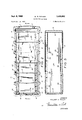
- FIG. 1 is a perspective View showing the improved lid rack partially slid-out from its track.
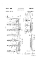
- FIG. 2 is a plan view of the lid rack in fully pushed-in or closed position.
- FIG. 3 is a vertical sectional view on line 33 of FIG. 2.
- FIG. 4 is a partial vertical sectional view showing the lid rack in fully pulled-out position.
- FIG. 5 is a horizontal sectional view on line 55 of FIG. 3.
- FIG. 6 is a partial transverse sectional view on line 66 of FIG. 3.
- the lid rack comprises a front transverse end wall 10, having an upper outturned rim flange 11 terminating in a depending lip 12 which serves as a finger-grip handle for pulling the rack outwardly from its support through a door opening or the like indicated in chain lines in FIG. 1.
- Longitudinally extending slightly diverging side walls 13 connect the front wall 10 wth a transverse rear end wall 14 preferably having a central substantially V-shaped opening 15 therein with an outturned flange 16 extending around the opening.
- end walls 10 and 14 are slightly divergent to each other.
- the side walls have a plurality of transverse partition walls 17 connected thereto and spaced at substantially equal intervals longitudinally thereof, forming a plurality of compartments.
- Five partition walls 17 are shown forming six compartments between the front and rear walls, but this number may be varied, as desired.
- each partition wall 17 has a central substantially V-shaped opening 15 therein in longitudinal alignment with the opening 15 in rear wall 14.
- openings not only save material but also make the lids in adjoining compartments more readily visible and accessible. Further, if several lids are stacked in one compartment the knob on the topmost lid can project through the adjoining openings 15 into the next compartment, thus accommodating an increased number of lids.
- the partition walls 17 taper from their top edges divergingly downward to an increased thickness at their bases. This gives greater lateral stability at the base where it is needed, and also facilitates molding the rack integrally.
- the outer edges of the partition walls 17 are connected to tapered upstanding sidewall portions 18 and similar tapered sidewall portions 19 and 20 are connected to the front and rear walls 10 and 14, respectively, forming substantially U-shaped openings 21 in opposite sides of each compartment.
- Outturned reinforcing flanges 22 extend around said openings and across the tops of sidewall portions 18, 19 and 20.
- the tapered sidewall portions are tapered from the top divergingly downward so that the upper ends of openings 21 are somewhat wider than their lower ends. This tapering also facilitates integral molding.
- the front three compartments have horizontal web walls 24 connected with the sidewalls 13 near their bottoms and with the bottom edges of partition walls 17, said web walls having central rectangular openings 25 therein to accommodate the lower edges of lids such as indicated in chain lines in FIG. 3.
- These web walls 24 impart lateral stability to the front half of the lid rack, especially when it is in a pulled-out position as seen in FIG. 1.
- horizontal guide ribs 26 project inwardly from both side walls 13 along the bottom edges thereof. As best shown in FIG. 6, these ribs project into longitudinal channels formed at the sides of a track between the track bottom wall 27 and angular outturned flanges 28. Preferably, the ribs 26 are spaced slightly above the bottom edges of the side walls 13, so that the bottom edges slide on the outer marginal portions of the track bottom wall.
- the bottom wall 27 may be secured to a shelf or other support by screws 29 passing through keyhole slots 30.
- a depending reverse bend 31 connecting the bottom of front end wall to the web wall 24 in the front compartment, contacts the front ends of the angular flanges 28 of the track to limit inward movement of the rack.
- An inturned rib 32 extending across the base of rear wall 14 contacts the heads of screws 29 to limit out- Ward movement of the rack as seen in FIG. 4.
- the entire rack is molded integrally of suitable plastic material, such as medium impact styrene, and the track may be molded or extruded from the same material.
- suitable plastic material such as medium impact styrene
- a laterally stable all-plastic, slide-out rack is provided which is very easy to install, which provides a plurality of compartments for selectively storing and removing different sized lids and which does not become chipped or bent and does not mar or mark the lids stored therein.
- An integral molded plastic slide-out lid rack having front and rear end walls and opposed side walls, longitudinally spaced transverse partition walls forming a plurality of compartments in said rack, said side walls having opposed upstanding portions connected to the outer edges of said partition walls and forming side openings in said compartments, and horizontal guide ribs projecting inwardly from the bases of said side walls for slidably interfitting a horizontal track.
- a horizontal track having side channels for slidably receiving said guide ribs, and means between said side channels for securing said track to a support.
Landscapes
- Engineering & Computer Science (AREA)
- Food Science & Technology (AREA)
- Details Of Rigid Or Semi-Rigid Containers (AREA)
Description
Sept. 9, 1969 w. D. TAYLOR SLIDE-OUT LID BACK 5 Sheets-Sheet 1 Filed Nov. 13, 1967 7 WILLIAM D. TAYLOR FIG.
ATTORNEYS Sept. 9, 1969 w. D. TAYLOR SLIDE-OUT LID RACK 3 Sheets-Sheet 2 Filed Nov. 13, 1967 III"! lllmllll I 1 ATTORNEYS Sept. 9, 1969 w. D. TAYLOR SLIDE-OUT LID RACK 3 Sheets-Sheet 3 Filed Nov. 13, 1967 WILL IAM D. TAYLOR n In.
iiliiil" 2 1 BY fi ATTORNEYS United States Patent O 3,465,892 SLIDE-OUT LID RACK William D. Taylor, Wooster, Ohio, assignor to Rubbergaid Incorporated, Wooster, Ohio, a corporation of hio Filed Nov. 13, 1967, Ser. No. 682,009
Int. Cl. A47g 19/08 US. Cl. 211-41 Claims ABSTRACT OF THE DISCLOSURE The invention relates generally to racks for holding kitchen pot and pan lids, and more particularly to a lid rack adapted to be slidably mounted on a cupboard shelf or the like for optimum accessibility.
BACKGROUND OF THE INVENTION Storing a variety of different size pot and pan lids in a kitchen has always been difficult because of the concavoconvex shape of most lids, the protruding handles and in some cases a depending rim flange. If the lids are merely laid one upon another in a drawer, the lowermost lids are never accessible and one has to lift and hold the top lids to get to the bot-tom ones.
Attempts have been made to provide lid racks of formed wire, but the wire must be coated to avoid corrosion and to prevent scratching or marring the lids, and such coating is apt to become chipped or removed as a result of constant insertion and removal of the lids tend ing to bend or kink the wire.
Moreover, where such racks have been fixedly mounted on a shelf, the lids are arranged one behind another and hence the inner lids are relatively inaccessible.
SUMMARY OF THE INVENTION The present novel and improved slide-out lid rack provides a drawer-like structure slidably mounted on a track supported on a shelf or the like so that the rack can be easily pulled out to make all the lids therein easily accessible. A plurality of laterally open compartments is formed by transverse partition walls having flanged side walls at their outer edges, the flanges being connected to form U-shaped openings in the side walls of the compartments.
It is an object of the present invention to provide an integral, molded plastic rack of the foregoing construction which is reinforced around the side openings, and the, front portion of which is further reinforced transversely for lateral stability when the rack is pulled out from its track.
Another object is to provide a molded plastic track having flanges for interfitting with guide flanges formed on the molded plastic rack.
These and other objects are accomplished by the novel and improved rack and track of the present invention shown in the accompanying drawings and described in detail in the following specification.
DESCRIPTION OF THE DRAWINGS A preferred embodiment of the invention is shown by way of example in the drawings in which:
FIG. 1 is a perspective View showing the improved lid rack partially slid-out from its track.
FIG. 2 is a plan view of the lid rack in fully pushed-in or closed position.
Patented Sept. 9, 1969 FIG. 3 is a vertical sectional view on line 33 of FIG. 2.
FIG. 4 is a partial vertical sectional view showing the lid rack in fully pulled-out position.
FIG. 5 is a horizontal sectional view on line 55 of FIG. 3.
FIG. 6 is a partial transverse sectional view on line 66 of FIG. 3.
The lid rack comprises a front transverse end wall 10, having an upper outturned rim flange 11 terminating in a depending lip 12 which serves as a finger-grip handle for pulling the rack outwardly from its support through a door opening or the like indicated in chain lines in FIG. 1. Longitudinally extending slightly diverging side walls 13 connect the front wall 10 wth a transverse rear end wall 14 preferably having a central substantially V-shaped opening 15 therein with an outturned flange 16 extending around the opening. As shown in FIG. 3 end walls 10 and 14 are slightly divergent to each other.
The side walls have a plurality of transverse partition walls 17 connected thereto and spaced at substantially equal intervals longitudinally thereof, forming a plurality of compartments. Five partition walls 17 are shown forming six compartments between the front and rear walls, but this number may be varied, as desired. Preferably, each partition wall 17 has a central substantially V-shaped opening 15 therein in longitudinal alignment with the opening 15 in rear wall 14.
These openings not only save material but also make the lids in adjoining compartments more readily visible and accessible. Further, if several lids are stacked in one compartment the knob on the topmost lid can project through the adjoining openings 15 into the next compartment, thus accommodating an increased number of lids.
As shown in FIG. 3, the partition walls 17 taper from their top edges divergingly downward to an increased thickness at their bases. This gives greater lateral stability at the base where it is needed, and also facilitates molding the rack integrally.
The outer edges of the partition walls 17 are connected to tapered upstanding sidewall portions 18 and similar tapered sidewall portions 19 and 20 are connected to the front and rear walls 10 and 14, respectively, forming substantially U-shaped openings 21 in opposite sides of each compartment. Outturned reinforcing flanges 22 extend around said openings and across the tops of sidewall portions 18, 19 and 20. As shown, the tapered sidewall portions are tapered from the top divergingly downward so that the upper ends of openings 21 are somewhat wider than their lower ends. This tapering also facilitates integral molding.
As shown in FIGS. 2, 3 and 6, the front three compartments have horizontal web walls 24 connected with the sidewalls 13 near their bottoms and with the bottom edges of partition walls 17, said web walls having central rectangular openings 25 therein to accommodate the lower edges of lids such as indicated in chain lines in FIG. 3. These web walls 24 impart lateral stability to the front half of the lid rack, especially when it is in a pulled-out position as seen in FIG. 1.
In the three rear compartments horizontal guide ribs 26 project inwardly from both side walls 13 along the bottom edges thereof. As best shown in FIG. 6, these ribs project into longitudinal channels formed at the sides of a track between the track bottom wall 27 and angular outturned flanges 28. Preferably, the ribs 26 are spaced slightly above the bottom edges of the side walls 13, so that the bottom edges slide on the outer marginal portions of the track bottom wall. The bottom wall 27 may be secured to a shelf or other support by screws 29 passing through keyhole slots 30.
Referring to FIG. 3, when the rack is in fully pushed-in position, a depending reverse bend 31, connecting the bottom of front end wall to the web wall 24 in the front compartment, contacts the front ends of the angular flanges 28 of the track to limit inward movement of the rack. An inturned rib 32 extending across the base of rear wall 14 contacts the heads of screws 29 to limit out- Ward movement of the rack as seen in FIG. 4.
The entire rack is molded integrally of suitable plastic material, such as medium impact styrene, and the track may be molded or extruded from the same material. Thus, a laterally stable all-plastic, slide-out rack is provided which is very easy to install, which provides a plurality of compartments for selectively storing and removing different sized lids and which does not become chipped or bent and does not mar or mark the lids stored therein.
I claim:
1. An integral molded plastic slide-out lid rack having front and rear end walls and opposed side walls, longitudinally spaced transverse partition walls forming a plurality of compartments in said rack, said side walls having opposed upstanding portions connected to the outer edges of said partition walls and forming side openings in said compartments, and horizontal guide ribs projecting inwardly from the bases of said side walls for slidably interfitting a horizontal track.
2. A lid rack as defined in claim 1, openings have outturned reinforcing along their edges.
3. A lid rack as defined in claim 1, in which said upstanding side wall portions are tapered divergingly downward.
4. A lid rack as defined in claim 2, in which said upin which said side flanges extending 4 standing side wall portions are tapered divergingly downward.
5. A lid rack as defined in claim 1, in which said partition walls are tapered in thickness divergingly downward.
6. A lid rack as defined in claim 4, in which said partition walls are tapered in thickness divergingly downward.
7. A lid rack as defined in claim 1, in which horizontal web walls connect the side walls and the partition walls in certain of said compartments.
8. A lid rack as defined in claim 4, in which horizontal! 7 web walls connect the side walls and the partition walls in certain of said compartments.
9. In combination with the lid rack as defined in claim 1, a horizontal track having side channels for slidably receiving said guide ribs, and means between said side channels for securing said track to a support.
10. A lid rack and track as defined in claim 9, in which an inner rib is provided on the base of the rear end wall for contacting said track securing means to limit outward movement of said rack.
References Cited UNITED STATES PATENTS 1,484,291 2/ 1924 Blakeslee 211-41 2,354,872 8/ 1944 Mitnick 21l-40 2,378,628 6/1945 Gray 211-41 FOREIGN PATENTS 734,977 8/ 1955 Great Britain.
JAMES A. LEPPINK, Primary Examiner
Applications Claiming Priority (1)
| Application Number | Priority Date | Filing Date | Title |
|---|---|---|---|
| US68200967A | 1967-11-13 | 1967-11-13 |
Publications (1)
| Publication Number | Publication Date |
|---|---|
| US3465892A true US3465892A (en) | 1969-09-09 |
Family
ID=24737811
Family Applications (1)
| Application Number | Title | Priority Date | Filing Date |
|---|---|---|---|
| US682009A Expired - Lifetime US3465892A (en) | 1967-11-13 | 1967-11-13 | Slide-out lid rack |
Country Status (1)
| Country | Link |
|---|---|
| US (1) | US3465892A (en) |
Cited By (21)
| Publication number | Priority date | Publication date | Assignee | Title |
|---|---|---|---|---|
| US3666115A (en) * | 1970-09-25 | 1972-05-30 | Rayson Engineering Pty Ltd | Plate storage system |
| DE3034963A1 (en) * | 1980-09-17 | 1982-08-19 | Institut für hauswirtschaftliche Produkt- und Verfahrens-Entwicklungs-Gesellschaft mbH, 6229 Eltville | Kitchen cupboard drawer with slidable holders - has holders movable along common guide rail with adjustable spacing to facilitate access |
| US4776469A (en) * | 1987-05-14 | 1988-10-11 | Geleziunas Rimas J | Rack for storing lids |
| US5207334A (en) * | 1991-09-26 | 1993-05-04 | Lear John E | Pot lid organizer and storage device |
| US5219079A (en) * | 1991-10-11 | 1993-06-15 | Rohm Co., Ltd. | Wafer jig |
| US5246195A (en) * | 1992-03-02 | 1993-09-21 | Huff Daniel C | Lid holder |
| USD362943S (en) | 1994-11-17 | 1995-10-03 | Yaffa Licari | Dish rack |
| US6131746A (en) * | 1999-08-04 | 2000-10-17 | Huang; Pao Ching | Pot lid storing trough |
| WO2004049880A1 (en) * | 2002-11-27 | 2004-06-17 | S. C. Johnson Home Storage, Inc. | Stacking device for thermoplastic containers and/or lids |
| USD500638S1 (en) | 2003-10-15 | 2005-01-11 | Each 2 Each, Inc. | Kitchen lid organizer |
| US20080251472A1 (en) * | 2007-04-16 | 2008-10-16 | Kasden Kenneth L | Cooking caddy |
| US20080314846A1 (en) * | 2007-06-21 | 2008-12-25 | Klein Richard B | Storage rack for pot and pan lids |
| USD629269S1 (en) * | 2010-03-11 | 2010-12-21 | Niko Okamoto | Canning funnel |
| US20140021153A1 (en) * | 2012-07-17 | 2014-01-23 | Ecolab Usa Inc. | Dish rack for oversized containers |
| US20140183148A1 (en) * | 2012-12-28 | 2014-07-03 | Allure Home Creation Co., Inc. | Magnetic Cookware Stands |
| USD747156S1 (en) * | 2012-12-31 | 2016-01-12 | Teresa M. Ferry | Drawer organizer |
| USD747630S1 (en) * | 2014-06-24 | 2016-01-19 | Spectrum Diversified Designs, Llc | Kitchen organizer |
| US9526377B2 (en) | 2014-04-03 | 2016-12-27 | Kendall Peter Weis | Lid storage system |
| US20200047833A1 (en) * | 2018-08-07 | 2020-02-13 | Delta Cycle Corporation | Adjustable bicycle stand |
| USD1059974S1 (en) * | 2023-02-22 | 2025-02-04 | Maria Jolanda Galassi | Pot lid rack |
| USD1122056S1 (en) * | 2024-12-19 | 2026-04-14 | Guangdong Nuomi Home Intelligent Technology Co., Ltd | Cookware basket |
Citations (4)
| Publication number | Priority date | Publication date | Assignee | Title |
|---|---|---|---|---|
| US1484291A (en) * | 1919-07-25 | 1924-02-19 | George S Blakeslee | Dish-holding basket |
| US2354872A (en) * | 1942-08-26 | 1944-08-01 | Mitnick Meyer | Record rack |
| US2378628A (en) * | 1944-08-31 | 1945-06-19 | Gray Joan | Dish drainer |
| GB734977A (en) * | 1953-05-13 | 1955-08-10 | Selcol Products Ltd | Improvements in or connected with racks or stands for gramophone discs or like shaped articles |
-
1967
- 1967-11-13 US US682009A patent/US3465892A/en not_active Expired - Lifetime
Patent Citations (4)
| Publication number | Priority date | Publication date | Assignee | Title |
|---|---|---|---|---|
| US1484291A (en) * | 1919-07-25 | 1924-02-19 | George S Blakeslee | Dish-holding basket |
| US2354872A (en) * | 1942-08-26 | 1944-08-01 | Mitnick Meyer | Record rack |
| US2378628A (en) * | 1944-08-31 | 1945-06-19 | Gray Joan | Dish drainer |
| GB734977A (en) * | 1953-05-13 | 1955-08-10 | Selcol Products Ltd | Improvements in or connected with racks or stands for gramophone discs or like shaped articles |
Cited By (23)
| Publication number | Priority date | Publication date | Assignee | Title |
|---|---|---|---|---|
| US3666115A (en) * | 1970-09-25 | 1972-05-30 | Rayson Engineering Pty Ltd | Plate storage system |
| DE3034963A1 (en) * | 1980-09-17 | 1982-08-19 | Institut für hauswirtschaftliche Produkt- und Verfahrens-Entwicklungs-Gesellschaft mbH, 6229 Eltville | Kitchen cupboard drawer with slidable holders - has holders movable along common guide rail with adjustable spacing to facilitate access |
| US4776469A (en) * | 1987-05-14 | 1988-10-11 | Geleziunas Rimas J | Rack for storing lids |
| US5207334A (en) * | 1991-09-26 | 1993-05-04 | Lear John E | Pot lid organizer and storage device |
| US5219079A (en) * | 1991-10-11 | 1993-06-15 | Rohm Co., Ltd. | Wafer jig |
| US5246195A (en) * | 1992-03-02 | 1993-09-21 | Huff Daniel C | Lid holder |
| USD362943S (en) | 1994-11-17 | 1995-10-03 | Yaffa Licari | Dish rack |
| US6131746A (en) * | 1999-08-04 | 2000-10-17 | Huang; Pao Ching | Pot lid storing trough |
| WO2004049880A1 (en) * | 2002-11-27 | 2004-06-17 | S. C. Johnson Home Storage, Inc. | Stacking device for thermoplastic containers and/or lids |
| USD500638S1 (en) | 2003-10-15 | 2005-01-11 | Each 2 Each, Inc. | Kitchen lid organizer |
| US20080251472A1 (en) * | 2007-04-16 | 2008-10-16 | Kasden Kenneth L | Cooking caddy |
| US20080314846A1 (en) * | 2007-06-21 | 2008-12-25 | Klein Richard B | Storage rack for pot and pan lids |
| USD629269S1 (en) * | 2010-03-11 | 2010-12-21 | Niko Okamoto | Canning funnel |
| US20140021153A1 (en) * | 2012-07-17 | 2014-01-23 | Ecolab Usa Inc. | Dish rack for oversized containers |
| US9549659B2 (en) * | 2012-07-17 | 2017-01-24 | Ecolab Usa Inc. | Dish rack for oversized containers |
| US20140183148A1 (en) * | 2012-12-28 | 2014-07-03 | Allure Home Creation Co., Inc. | Magnetic Cookware Stands |
| USD747156S1 (en) * | 2012-12-31 | 2016-01-12 | Teresa M. Ferry | Drawer organizer |
| US9526377B2 (en) | 2014-04-03 | 2016-12-27 | Kendall Peter Weis | Lid storage system |
| USD747630S1 (en) * | 2014-06-24 | 2016-01-19 | Spectrum Diversified Designs, Llc | Kitchen organizer |
| US20200047833A1 (en) * | 2018-08-07 | 2020-02-13 | Delta Cycle Corporation | Adjustable bicycle stand |
| US10858055B2 (en) * | 2018-08-07 | 2020-12-08 | Delta Cycle Corporation | Adjustable bicycle stand |
| USD1059974S1 (en) * | 2023-02-22 | 2025-02-04 | Maria Jolanda Galassi | Pot lid rack |
| USD1122056S1 (en) * | 2024-12-19 | 2026-04-14 | Guangdong Nuomi Home Intelligent Technology Co., Ltd | Cookware basket |
Similar Documents
| Publication | Publication Date | Title |
|---|---|---|
| US3465892A (en) | Slide-out lid rack | |
| US4592471A (en) | Bakeware organizer | |
| US4515421A (en) | Multiple use shelf for cooler | |
| US4561705A (en) | Compartmented transport and storage container | |
| USRE32740E (en) | Multiple use shelf for cooler | |
| US5486046A (en) | Cantilever slide out refrigerator shelf | |
| US4372444A (en) | Stackable/nestable/dividable storage bin | |
| US5244272A (en) | Space-saving undercabinet spice jar drawer | |
| US5044704A (en) | Adjustable refrigerator crisper drawer structure | |
| US5176281A (en) | Tackle box with lid-latching handle and removable carrying case | |
| US7219969B2 (en) | Storage container and storage system including a stack of the same | |
| US5482162A (en) | Tool chest assembly constructed of a plastic material | |
| US5323917A (en) | Refrigerator rack | |
| US3053397A (en) | Utility bins | |
| US4932548A (en) | Space divider assembly for a freezer chest | |
| US3141569A (en) | Unitary article as a tissue dispenser and litter container | |
| US5426885A (en) | Tackle tote | |
| US2704699A (en) | Cabinet | |
| US1565993A (en) | Disk-record container or cabinet | |
| US3482708A (en) | Stacking trays | |
| US5826730A (en) | File folder organizer | |
| US3542446A (en) | Container for storage bins | |
| US5201575A (en) | Container storage cabinet | |
| US3079206A (en) | Knock-down and stackable cabinet with accessories | |
| US5007552A (en) | Serving bar and container for food |