US3452683A - Cog driven rack rail locomotive - Google Patents
Cog driven rack rail locomotive Download PDFInfo
- Publication number
- US3452683A US3452683A US633494A US3452683DA US3452683A US 3452683 A US3452683 A US 3452683A US 633494 A US633494 A US 633494A US 3452683D A US3452683D A US 3452683DA US 3452683 A US3452683 A US 3452683A
- Authority
- US
- United States
- Prior art keywords
- cogwheels
- cograil
- plane
- locomotive
- guide rails
- Prior art date
- Legal status (The legal status is an assumption and is not a legal conclusion. Google has not performed a legal analysis and makes no representation as to the accuracy of the status listed.)
- Expired - Lifetime
Links
- 230000003137 locomotive effect Effects 0.000 title description 30
- 238000009434 installation Methods 0.000 description 5
- 239000000725 suspension Substances 0.000 description 4
- 238000005452 bending Methods 0.000 description 3
- 230000005540 biological transmission Effects 0.000 description 3
- 238000005096 rolling process Methods 0.000 description 3
- 241000272194 Ciconiiformes Species 0.000 description 2
- 230000008901 benefit Effects 0.000 description 2
- 238000010276 construction Methods 0.000 description 2
- 230000008878 coupling Effects 0.000 description 2
- 238000010168 coupling process Methods 0.000 description 2
- 238000005859 coupling reaction Methods 0.000 description 2
- 238000005065 mining Methods 0.000 description 2
- 230000008859 change Effects 0.000 description 1
- 230000009977 dual effect Effects 0.000 description 1
- 230000003993 interaction Effects 0.000 description 1
- 239000000463 material Substances 0.000 description 1
- 230000004048 modification Effects 0.000 description 1
- 238000012986 modification Methods 0.000 description 1
Images
Classifications
-
- B—PERFORMING OPERATIONS; TRANSPORTING
- B61—RAILWAYS
- B61C—LOCOMOTIVES; MOTOR RAILCARS
- B61C11/00—Locomotives or motor railcars characterised by the type of means applying the tractive effort; Arrangement or disposition of running gear other than normal driving wheel
- B61C11/04—Locomotives or motor railcars characterised by the type of means applying the tractive effort; Arrangement or disposition of running gear other than normal driving wheel tractive effort applied to racks
Definitions
- the invention therefore avoids the use of friction wheels as driving wheels of the vehicle acting as a locomotive, and operates with driving wheels which positively engage the rails.
- Driving vehicles have already been proposed which are carried between the two parts of the framework of the ribbon train installation and which are equipped with a cogwheel which rotates like the cogwheel of a cog railway about a horizontal axis and engages, for example, into a central cograil.
- Such driving vehicles can be used, in appropriately modified form, in single-track ribbon train installations.
- upwardly directed forces are produced which are not counteracted by the relatively light weight of the driving vehicle, and are therefore transferred to its running wheels and their guiding means which secure them against lifting.
- the cogwheels associated with the driving vehicle of the invention therefore, rotate pairwise in opposite senses about vertical axes, that is, their plane of rotation and their sense of rotation is the same as those of the friction drive wheels of the driving vehicles mentioned earlier.
- the forces produced perpendicularly to the cograil axis as the two cogwheels of each pair roll on the cograil cancel one another, i.e., they are directly absorbed in the frame in which the cogwheels are fastened, without causing this frame to attempt to pull itself, or the vehicle associated with it, out of its guiding rails.
- the driving wheels are no longer constructed as friction wheels, the need to urge them against the traction rail and to mount them movably in the frame for this purpose, is eliminated; a positive engagement between drive wheels and rails is created which is reliably effective under all circumstances, and since the pair of cogwheels can be designed to engage a pair of external cograils, as well as a single internal cograil, the traction rail no longer needs to consist of a third center rail, and the cograil or rack required for the engagement of the cogwheels can also be provided on the lateral channels which are needed in any case for the guidance of the ribbon train.
- the cograils cooperate with cogwheels which revolve in the horizontal plane, the additional advantage is offered over the normal cograil drive that the cograils have their teeth facing sideways instead of up, so that they are better protected against dirt and against the lodging of foreign bodies between the teeth.
- the invention proposes the arrangement of the cogwheels in a chassis frame which is suspended articulately on all sides between two carriages which are positively guided by the guiding rails of the ribbon train.
- the invention which relates to a driving vehicle which is carried in ribbon train guides consisting preferably of channel bars and which has driving wheels arranged in pairs which rotate on vertical axes and roll in opposite senses on rails disposed parallel to the ribbon train guiding rails, is thus characterized in that the driving wheels are made in the form of cogwheels, each driving wheel of a pair of such cogwheels being meshed with a rail provided with teeth, and the pairs of cogwheels being fastened in a frame which is suspended articulately on all sides between two carriages positively guided in the guiding rails of the ribbon train.
- cogwheels are used which engage from both sides into a central rack or cograil.
- This cograil can best consist of two flat bars disposed one above the other, with a series of cog pins arranged between them, the path of contact of the cograil being matched to the pitch circles of the two cogwheels.
- the two cogwheels are arranged in separate horizontal planes. As long as both cogwheels rotate with the same speed, the frame on which the cogwheels are mounted progresses along the cograil.
- the frame On curves the frame is steered by the guiding rollers of the carriage serving for its suspension along the guiding rails of the ribbon train framework or trestle, and this pivoting movement of the frame imparts to the axis of the cogwheel on the outside of the curve an additional forward thrust, and the axis of the other cogwheel is displaced rearward, without thereby producing a change in the rotatory speed of the two cogwheels.
- the two cogwheels can therefore be associated with a common transmission and a common motor.
- the frame should not assume a vertical tilt in relation to the cograil because the result would be that the teeth of the cogwheels would contact the pins in the cograil only with their edges instead of on their full width. Such a point contact or line contact instead of the desirable broad-surface contact between the teeth and the pins would result in heavy wear.
- the suspension of the frame on the carriages must be articulate and permit passage through vertical ups and downs, as well as horizontal curves. Care must therefore be taken to see that the transmission of the traction forces exercised by the cogwheels on the carriage and on the ribbon train being pulled by the driving vehicle does not result in any components seeking to lift the frame at one end.
- the articulations serving for the suspension of the frame are disposed in the middle plane of rotation of the cogwheels, so that these traction forces will always tend to keep the frame in this plane of rotation or parallel thereto.
- this vertical joint can be a ball joint which simultaneously permits the horizontal tilting movements between the carriages and frame.
- this is not possible since such a joint would have to lie not only in the horizontal but also in the vertical plane of the cograil.
- the invention therefore proposes in this case to provide for the vertical deflections two pin joints which are disposed on both sides of the central cograil, and for the horizontal deflections to provide likewise one or two pin joints which are disposed in front of and/or behind the vertical joints, above the central cograil in each case.
- the pivots are exposed to bending stresses, such as would not occur in the case of a knuckle joint or a ball joint.
- the plates joined with one another by the pin joint must lie on one another without free plan and on a relatively large area, or the pivot pin must be mounted in a fork formed by two superimposed plates.
- Another object of the invention is to provide a locomotive vehicle as aforesaid, which has a low overall height for travelling through passageways of limited height.
- a further object of the invention is to provide a locomotive vehicle as aforesaid wherein the weight of the vehicle is principally supported on guide rails and is driven by a pair of horizontally rotating cogwheels that engage the cograil means.
- Still another and further object of the invention is to provide a locomotive vehicle as aforesaid, which is capable of negotiating curves and changes in grade.
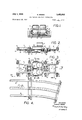
- FIG. 1 is a transverse section elevation view along the line 1-1 of FIG. 3 looking in the direction of the arrows of a locomotive vehicle according to a preferred embodiment of the invention, illustrating the arrangement of the driving cogwheels in relation to the cograil means and the lateral guide rails;
- FIG. 2 is a side elevation view of the locomotive vehicle shown in FIG. 1;
- FIG. 3 is a plan view of the locomotive vehicle shown in FIGS. 1 and 2;
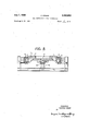
- FIG. 4 is a plan view of a typical track length section used by the locomotive vehicle of FIGS. 1-3, and illustrating the arrangement of the lateral guide rails in relation to a central cograil;
- FIG. 5 is a transverse sectional view of the locomotive of FIG. 3 taken along the line VV looking in the direction of the arrows.
- the locomotive vehicle V is illustrated for simplicity as a basic chassis means without any superstructure, such as a car body (not shown) or flat bed (not shown), which ordinarily would be attached to such chassis for carrying persons, objects or materials.
- the vehicle V is essentially driven by a pair of rotatable cogwheels 1 and 2, which are carried on a base frame 3 of the chassis means, the other parts of which include carriages 4 and S, which are articulately connected to base frame 3 at respectively opposite ends thereof, as shown by FIGS. 2 and 3.
- Each of the carriages 4 and 5 has rotatable wheels 6 and 7 which are arranged for rolling contact engagement with a pair of elongated guide rails 8 which extend in laterally spaced-apart parallel relation to each other, as shown by FIG. 4.
- the guide rails 8 are in the form of U-shaped channels oriented with their open sides facing each other, as shown by FIG. 1, so that the vertical plane rotating wheels 6 ride on the upper surface of the lower guide rail flanges and the horizontal plane rotating wheels 7 ride against the inside edge of the upper guide rail flanges, whereby the carriages 4 and 5 are supported and guided for movement together with the base frame which they support along the path defined by the guide rails 8.
- the cogwheels are positioned for meshing engagement with a central cograil 9, which is centrally located between guide rails 8 and extends lengthwise in parallel relation thereto, as in FIG. 4.
- Cograil 9 can be expediently a wide flange or I-beam section having double-headed bolts or rivets 10 extended through its web portion to define a double cog rack, such rivets 10 being spaced in accordance with the pitch of cogwheels 1 and 2, each to function as a cog, thereby affording a somewhat Simpler and less expensive cograil 9 structure as compared to using machined rack sections (not shown) mounted on each rail web side.
- the cog wheels are arranged for rotation in opposite directions about parallel axes, generally perpendicular to the plane of the guide rails 8, and are laterally spacedapart for meshing engagement with the cograil 9 which passes between them.
- the web portions between the rivets 10 on cograil 9 can be cut out so that the teeth of the cogwheels 1 and 2 can extend through the rail web for positive gripping engagement therewith.
- the cogwheels 1 and 2 are axially displaced from each other to rotate in separate but parallel planes, thereby allowing the teeth of both cogwheels 1 and 2 to extend into the same cograil 9 openings, as illustrated in FIG. 1.
- the rotary driving of cogwheels 1 and 2 can be accomplished by any conventional motor means, but is expediently performed by a motor means having a pair of individual motors 11 coupled to a dual rotary output transmission 12 which is coupled to each cogwheel 1 and 2.
- cograil means having separate, spaced-apart cograils (not shown) can be substituted, as for example a pair of cograils each mounted under a guide rail 8 and extending in parallel relation therewith.
- cogwheels 1 and 2 would be arranged similarly as shown by FIG. 1, except that they could be spaced further apart each to mesh with a corresponding cograil, and with a sufficient cograil spacing, such cogwheels 1 and 2 could rotate in the same horizontal plane.
- each carriage 4 and 5 is articulately connected to the base frame 3 to support same in suspension therebetween by a coupling means C having a pair of end joints 13 allowing articulation in a plane parallel to the plane of guide rails 8, and an intermediate joint 14 allowing articulation in a plane perpendicular to the plane of guide rails 8.
- the horizontal articulation joints 13 are suitably reinforced against vertical plane bending and are located one directly adjacent to the base frame 3 and the other directly adjacent to the respective carriage 4, 5.
- the base frame 3 necessarily must be of correspondingly elongated construction and at least one of the cogwheels must be displaceable laterally against a resilient means such as a spring, in order to assure perfect engagement of such cogwheels with the guide rail along curved length sections.
- a locomotive vehicle which comprises a chassis means disposed for movement along a pair of parallel elongated guide rails adapted to support such vehicle in guided engagement therewith; a pair of cog wheels carried by said chassis means and disposed for rotation in opposite directions to each other about difierent axes, each of which axes is generally perpendicular to the plane defined by said guide rails; elongated cog rail means extending in parallel relationship to and between side guide rails, wherein said cogwheels engage said cograil in meshing engagement on opposite sides thereof; and means adapted to drive said cogwheels whereby to propel said chassis along said rails.
- said chassis means includes a base means carrying said cogwheels, a first carriage means articulately connected to said base means at one end thereof, and a second carriage means articulately connected to said base means at an opposite end thereof, said first and second carriage means each having rotatable wheels disposed for engagement with said guide rails for support thereby and for guided movement therealong together with said base means, said base means being suspended between said first and second carriage means for support thereby.
- first and second carriage means are each articulately connected to the base means by a coupling means having a pair of end joints allowing articulation in a plane parallel to the plane of the guide rails, and a joint intermediate with respect to said end joints and allowing articulation in a plane perpendicular to the plane of said guide rails, said parallel plane articulation joints being one located directly adjacent the base means and the other directly adjacent to the respective carriage means.
- the locomotive vehicle according to claim 7 including motor means supported by said base means for movement therewith and coupled to each of said cogwheels to rotatably drive same.
Landscapes
- Engineering & Computer Science (AREA)
- Transportation (AREA)
- Mechanical Engineering (AREA)
- Power-Operated Mechanisms For Wings (AREA)
Description
July I, 1969 K. GREBE 7 3,452,683
COG DRIVEN RACK RAIL LOCOMOTIVE Filed A ril 25, 1967 v Sheet of 2 ll-- 1 I 9' 2 I T i H T I a I l 9 10 i l fl D 1* 2 1-, u 1"" I I I 8 g F. I 11 l I l INVENTOR KONRAD GREBE ATTORNEYS.
y 1969 K. GREBE 3,452,683
COG DRIVEN RACK RAIL LOCOMOT IVE Filed April 25, 1967 Sheet of 2 ATTORNEYS.
United States Patent 3,452,683 COG DRIVEN RACK RAIL LOCOMOTIVE Konrad Grebe, Auf Dem Nutzenberg 1, Wuppertal-Elberfeld, Germany Filed Apr. 25, 1967, Ser. No. 633,494 Int. Cl. B61c 11/04; B61b 13/02 US. Cl. 10529 9 Claims ABSTRACT OF THE DISCLOSURE The present invention relates to a locomotive vehicle which is adapted to travel along rails and is driven by cogwheels that mesh with a cograil means.
In conventional railway systems, locomotives are propelled along guide rails by rolling contact friction between such rails and the locomotive drive wheels, which for most railway grades is satisfactory because the weight of the locomotive itself presses the drive wheels firmly against the upper surfaces of the rails. However, in certain railway installations, commonly known as ribbon trains and used in underground mines, conventional railway systems are unsatisfactory for travel in passages of limited height because of the height taken up by their wheels, which rotate about axes parallel to the plane of the rails.
To reduce the wheel height consumption in such ribbon trains, it has been proposed to use pairs of friction drive wheels which engage a central rail extending between a pair of guide rails parallel thereto, which friction drive wheels rotate in a horizontal plane, i.e. parallel to the plane of the guide rails, about vertical axes, i.e. axes perpendicular to the plane of the guide rails. Such pro posed locomotive driving arrangement is subject to the disadvantage that because of the horizontal drive wheels, the locomotive weight is no longer available to press the drive wheels against the central rail, and in order to obtain sufficient tractive friction for driving, it is necessary to expend considerable power to press the drive wheels against the central rail by auxiliary means.
The invention therefore avoids the use of friction wheels as driving wheels of the vehicle acting as a locomotive, and operates with driving wheels which positively engage the rails. Driving vehicles have already been proposed which are carried between the two parts of the framework of the ribbon train installation and which are equipped with a cogwheel which rotates like the cogwheel of a cog railway about a horizontal axis and engages, for example, into a central cograil. Such driving vehicles can be used, in appropriately modified form, in single-track ribbon train installations. However, when the cogwheel rolls on the cog rail, upwardly directed forces are produced which are not counteracted by the relatively light weight of the driving vehicle, and are therefore transferred to its running wheels and their guiding means which secure them against lifting. These forces can be kept slight if the cogwheel has a large diameter and a small tooth pitch. In the low headroom necessitated by the cramped conditions in mining operations, however (underground mining is the principal field of application of ribbon train installations), there is a tight limit on the diameter that such a cogwheel can have. Furthermore, in dips and rises in the framework, difliculties would arise in the interaction between the running wheels and the cogwheel.
The cogwheels associated with the driving vehicle of the invention, therefore, rotate pairwise in opposite senses about vertical axes, that is, their plane of rotation and their sense of rotation is the same as those of the friction drive wheels of the driving vehicles mentioned earlier. In this case, the forces produced perpendicularly to the cograil axis as the two cogwheels of each pair roll on the cograil, cancel one another, i.e., they are directly absorbed in the frame in which the cogwheels are fastened, without causing this frame to attempt to pull itself, or the vehicle associated with it, out of its guiding rails.
However, since the driving wheels are no longer constructed as friction wheels, the need to urge them against the traction rail and to mount them movably in the frame for this purpose, is eliminated; a positive engagement between drive wheels and rails is created which is reliably effective under all circumstances, and since the pair of cogwheels can be designed to engage a pair of external cograils, as well as a single internal cograil, the traction rail no longer needs to consist of a third center rail, and the cograil or rack required for the engagement of the cogwheels can also be provided on the lateral channels which are needed in any case for the guidance of the ribbon train.
Since the cograils cooperate with cogwheels which revolve in the horizontal plane, the additional advantage is offered over the normal cograil drive that the cograils have their teeth facing sideways instead of up, so that they are better protected against dirt and against the lodging of foreign bodies between the teeth.
On the other hand, it now becomes necessary to assure the correct rolling of the cogwheels on the teeth provided on the guiding rails associated with them. To this end the invention proposes the arrangement of the cogwheels in a chassis frame which is suspended articulately on all sides between two carriages which are positively guided by the guiding rails of the ribbon train.
The invention, which relates to a driving vehicle which is carried in ribbon train guides consisting preferably of channel bars and which has driving wheels arranged in pairs which rotate on vertical axes and roll in opposite senses on rails disposed parallel to the ribbon train guiding rails, is thus characterized in that the driving wheels are made in the form of cogwheels, each driving wheel of a pair of such cogwheels being meshed with a rail provided with teeth, and the pairs of cogwheels being fastened in a frame which is suspended articulately on all sides between two carriages positively guided in the guiding rails of the ribbon train. In this manner a driving vehicle is created whose application is not limited to the operation of ribbon trains, although it is especially and universally useful in ribbon train installations, and which avoids the disadvantages of the prior art driving vehicles equipped with friction wheels, as well as the disadvantages of the prior art cograil locomotives.
Preferentially, cogwheels are used which engage from both sides into a central rack or cograil. This cograil can best consist of two flat bars disposed one above the other, with a series of cog pins arranged between them, the path of contact of the cograil being matched to the pitch circles of the two cogwheels.
In order that the axes of the cogwheels engaging the cograil from the right and from the left may be located symmetrically to the cograil and that both cogwheels may engage the same cogs in the cograil together, the two cogwheels are arranged in separate horizontal planes. As long as both cogwheels rotate with the same speed, the frame on which the cogwheels are mounted progresses along the cograil. On curves the frame is steered by the guiding rollers of the carriage serving for its suspension along the guiding rails of the ribbon train framework or trestle, and this pivoting movement of the frame imparts to the axis of the cogwheel on the outside of the curve an additional forward thrust, and the axis of the other cogwheel is displaced rearward, without thereby producing a change in the rotatory speed of the two cogwheels. The two cogwheels can therefore be associated with a common transmission and a common motor. These considerations, of course, do not apply to a pair of cogwheels engaging exterior cograils.
In any case, it is important that the frame should not assume a vertical tilt in relation to the cograil because the result would be that the teeth of the cogwheels would contact the pins in the cograil only with their edges instead of on their full width. Such a point contact or line contact instead of the desirable broad-surface contact between the teeth and the pins would result in heavy wear. On the other hand, the suspension of the frame on the carriages must be articulate and permit passage through vertical ups and downs, as well as horizontal curves. Care must therefore be taken to see that the transmission of the traction forces exercised by the cogwheels on the carriage and on the ribbon train being pulled by the driving vehicle does not result in any components seeking to lift the frame at one end. According to a further feature of the invention, therefore, the articulations serving for the suspension of the frame, to the extent that they permit a vertical tilt, are disposed in the middle plane of rotation of the cogwheels, so that these traction forces will always tend to keep the frame in this plane of rotation or parallel thereto.
In the case of cogwheels which engage in externally disposed cograils, this vertical joint can be a ball joint which simultaneously permits the horizontal tilting movements between the carriages and frame. In the case of cogwheels which engage a central cograil, this is not possible since such a joint would have to lie not only in the horizontal but also in the vertical plane of the cograil. The invention therefore proposes in this case to provide for the vertical deflections two pin joints which are disposed on both sides of the central cograil, and for the horizontal deflections to provide likewise one or two pin joints which are disposed in front of and/or behind the vertical joints, above the central cograil in each case. Since the vertical joints and the horizontal joints are disposed one behind the other and not in the same plane, the pivots are exposed to bending stresses, such as would not occur in the case of a knuckle joint or a ball joint. In order to reinforce the horizontal joints against such bending forces, the plates joined with one another by the pin joint must lie on one another without free plan and on a relatively large area, or the pivot pin must be mounted in a fork formed by two superimposed plates.
It is therefore an object of the invention to provide a locomotive vehicle adapted for driving along a cograil means.
Another object of the invention is to provide a locomotive vehicle as aforesaid, which has a low overall height for travelling through passageways of limited height.
A further object of the invention is to provide a locomotive vehicle as aforesaid wherein the weight of the vehicle is principally supported on guide rails and is driven by a pair of horizontally rotating cogwheels that engage the cograil means.
Still another and further object of the invention is to provide a locomotive vehicle as aforesaid, which is capable of negotiating curves and changes in grade.
Other and further objects and advantages of the invention will become apparent from the following detailed description and accompanying drawing in which:
FIG. 1 is a transverse section elevation view along the line 1-1 of FIG. 3 looking in the direction of the arrows of a locomotive vehicle according to a preferred embodiment of the invention, illustrating the arrangement of the driving cogwheels in relation to the cograil means and the lateral guide rails;
FIG. 2 is a side elevation view of the locomotive vehicle shown in FIG. 1;
FIG. 3 is a plan view of the locomotive vehicle shown in FIGS. 1 and 2;
FIG. 4 is a plan view of a typical track length section used by the locomotive vehicle of FIGS. 1-3, and illustrating the arrangement of the lateral guide rails in relation to a central cograil; and
FIG. 5 is a transverse sectional view of the locomotive of FIG. 3 taken along the line VV looking in the direction of the arrows.
Referring now to the drawing, the locomotive vehicle V is illustrated for simplicity as a basic chassis means without any superstructure, such as a car body (not shown) or flat bed (not shown), which ordinarily would be attached to such chassis for carrying persons, objects or materials. The vehicle V is essentially driven by a pair of rotatable cogwheels 1 and 2, which are carried on a base frame 3 of the chassis means, the other parts of which include carriages 4 and S, which are articulately connected to base frame 3 at respectively opposite ends thereof, as shown by FIGS. 2 and 3.
Each of the carriages 4 and 5 has rotatable wheels 6 and 7 which are arranged for rolling contact engagement with a pair of elongated guide rails 8 which extend in laterally spaced-apart parallel relation to each other, as shown by FIG. 4. The guide rails 8 are in the form of U-shaped channels oriented with their open sides facing each other, as shown by FIG. 1, so that the vertical plane rotating wheels 6 ride on the upper surface of the lower guide rail flanges and the horizontal plane rotating wheels 7 ride against the inside edge of the upper guide rail flanges, whereby the carriages 4 and 5 are supported and guided for movement together with the base frame which they support along the path defined by the guide rails 8.
The cogwheels are positioned for meshing engagement with a central cograil 9, which is centrally located between guide rails 8 and extends lengthwise in parallel relation thereto, as in FIG. 4.
Cograil 9 can be expediently a wide flange or I-beam section having double-headed bolts or rivets 10 extended through its web portion to define a double cog rack, such rivets 10 being spaced in accordance with the pitch of cogwheels 1 and 2, each to function as a cog, thereby affording a somewhat Simpler and less expensive cograil 9 structure as compared to using machined rack sections (not shown) mounted on each rail web side.
The cog wheels are arranged for rotation in opposite directions about parallel axes, generally perpendicular to the plane of the guide rails 8, and are laterally spacedapart for meshing engagement with the cograil 9 which passes between them. To assure a more reliable cogwheel 1, 2 engagement, the web portions between the rivets 10 on cograil 9 can be cut out so that the teeth of the cogwheels 1 and 2 can extend through the rail web for positive gripping engagement therewith. In such case, the cogwheels 1 and 2 are axially displaced from each other to rotate in separate but parallel planes, thereby allowing the teeth of both cogwheels 1 and 2 to extend into the same cograil 9 openings, as illustrated in FIG. 1.
The rotary driving of cogwheels 1 and 2 can be accomplished by any conventional motor means, but is expediently performed by a motor means having a pair of individual motors 11 coupled to a dual rotary output transmission 12 which is coupled to each cogwheel 1 and 2.
It should be noted that the invention is not necessarily restricted to a central cograil 9 arrangement, and, if desired, a cograil means having separate, spaced-apart cograils (not shown) can be substituted, as for example a pair of cograils each mounted under a guide rail 8 and extending in parallel relation therewith. With such a separated cograil configuration, the cogwheels 1 and 2 would be arranged similarly as shown by FIG. 1, except that they could be spaced further apart each to mesh with a corresponding cograil, and with a sufficient cograil spacing, such cogwheels 1 and 2 could rotate in the same horizontal plane.
As shown better by FIGS. 2 and 3, each carriage 4 and 5 is articulately connected to the base frame 3 to support same in suspension therebetween by a coupling means C having a pair of end joints 13 allowing articulation in a plane parallel to the plane of guide rails 8, and an intermediate joint 14 allowing articulation in a plane perpendicular to the plane of guide rails 8. The horizontal articulation joints 13 are suitably reinforced against vertical plane bending and are located one directly adjacent to the base frame 3 and the other directly adjacent to the respective carriage 4, 5.
As can be appreciated from the foregoing, it is possible instead of using a pair of cogwheels 1 and 2, to substitute 3 rotatably driven cogwheels (not shown) disposed in tandem and laterally staggered, all of such 3 cogwheels being carried by the base frame 3. However, with such construction, the base frame 3 necessarily must be of correspondingly elongated construction and at least one of the cogwheels must be displaceable laterally against a resilient means such as a spring, in order to assure perfect engagement of such cogwheels with the guide rail along curved length sections.
As can be appreciated by the artisan, the invention described herein is susceptible of numerous modifications and variations, as will become obvious from the foregoing description, in terms of a limited number of embodiments. However, the invention is intended to be limited only by the following claims wherein I have endeavored to claim all inherent novelty.
What is claimed is:
1. A locomotive vehicle which comprises a chassis means disposed for movement along a pair of parallel elongated guide rails adapted to support such vehicle in guided engagement therewith; a pair of cog wheels carried by said chassis means and disposed for rotation in opposite directions to each other about difierent axes, each of which axes is generally perpendicular to the plane defined by said guide rails; elongated cog rail means extending in parallel relationship to and between side guide rails, wherein said cogwheels engage said cograil in meshing engagement on opposite sides thereof; and means adapted to drive said cogwheels whereby to propel said chassis along said rails.
2. The locomotive vehicle according to claim 1 wherein said cogwheels are disposed for rotation about generally parallel axes and are laterally spaced-apart, each for meshing engagement with a separate, spaced-apart section of said cograil means.
3. The locomotive vehicle according to claim 1 wherein said cogwheels are disposed for rotation about generally parallel axes and are laterally spaced-apart for meshing engagement with a cograil means centrally located with respect to said cogwheels and extending therebetween.
4. The locomotive vehicle according to claim 3 wherein said cogwheels are disposed for rotation in opposite directions and in separated parallel planes.
5. The locomotive vehicle according to claim 3 wherein said chassis means includes a base means carrying said cogwheels, a first carriage means articulately connected to said base means at one end thereof, and a second carriage means articulately connected to said base means at an opposite end thereof, said first and second carriage means each having rotatable wheels disposed for engagement with said guide rails for support thereby and for guided movement therealong together with said base means, said base means being suspended between said first and second carriage means for support thereby.
6. The locomotive vehicle according to claim 5 wherein said first and second carriage means are articulately connected to said base means for articulate movement relative thereto in a plane generally parallel to said guide rails, and also for articulate movement relative thereto in a plane generally perpendicular to the plane of said guide rails.
7. The locomotive vehicle according to claim 6 wherein said first and second carriage means are connected to the base means for articulate movement relative thereto in a plane perpendicular to the plane of said guide rails and extending between the rotation axes of said cogwheels in symmetrical relation thereto.
8. The locomotive vehicle according to claim 7 wherein said first and second carriage means are each articulately connected to the base means by a coupling means having a pair of end joints allowing articulation in a plane parallel to the plane of the guide rails, and a joint intermediate with respect to said end joints and allowing articulation in a plane perpendicular to the plane of said guide rails, said parallel plane articulation joints being one located directly adjacent the base means and the other directly adjacent to the respective carriage means.
9. The locomotive vehicle according to claim 7 including motor means supported by said base means for movement therewith and coupled to each of said cogwheels to rotatably drive same.
References Cited UNITED STATES PATENTS 594,832 11/1897 Leland 29 1,523,363 1/1925 Howell 10529 3,084,766 4/1963 Donaldson 10529 ARTHUR L. LA POINT, Primary Examiner.
HOWARD BELTRAN, Assistant Examiner.
US. Cl. X.R. l04243, 247; 105-2l5
Applications Claiming Priority (1)
| Application Number | Priority Date | Filing Date | Title |
|---|---|---|---|
| US63349467A | 1967-04-25 | 1967-04-25 |
Publications (1)
| Publication Number | Publication Date |
|---|---|
| US3452683A true US3452683A (en) | 1969-07-01 |
Family
ID=24539854
Family Applications (1)
| Application Number | Title | Priority Date | Filing Date |
|---|---|---|---|
| US633494A Expired - Lifetime US3452683A (en) | 1967-04-25 | 1967-04-25 | Cog driven rack rail locomotive |
Country Status (1)
| Country | Link |
|---|---|
| US (1) | US3452683A (en) |
Cited By (1)
| Publication number | Priority date | Publication date | Assignee | Title |
|---|---|---|---|---|
| US6264330B1 (en) | 1996-12-30 | 2001-07-24 | Sony Corporation | Self-propelled camera dolly |
Citations (3)
| Publication number | Priority date | Publication date | Assignee | Title |
|---|---|---|---|---|
| US594832A (en) * | 1897-11-30 | leland | ||
| US1523363A (en) * | 1925-01-13 | Locomotive ob cae | ||
| US3084766A (en) * | 1961-01-16 | 1963-04-09 | David R Donaldson | Lifts with inclined track |
-
1967
- 1967-04-25 US US633494A patent/US3452683A/en not_active Expired - Lifetime
Patent Citations (3)
| Publication number | Priority date | Publication date | Assignee | Title |
|---|---|---|---|---|
| US594832A (en) * | 1897-11-30 | leland | ||
| US1523363A (en) * | 1925-01-13 | Locomotive ob cae | ||
| US3084766A (en) * | 1961-01-16 | 1963-04-09 | David R Donaldson | Lifts with inclined track |
Cited By (3)
| Publication number | Priority date | Publication date | Assignee | Title |
|---|---|---|---|---|
| US6264330B1 (en) | 1996-12-30 | 2001-07-24 | Sony Corporation | Self-propelled camera dolly |
| US6520641B1 (en) | 1996-12-30 | 2003-02-18 | Sony Corporation | Shooting a motion picture scene with a self-propelled camera dolly |
| US6523957B1 (en) | 1996-12-30 | 2003-02-25 | Sony Corporation | Flexible coupling for a self-propelled camera dolly |
Similar Documents
| Publication | Publication Date | Title |
|---|---|---|
| KR960008199B1 (en) | Method of changing wheel spacing of railway vehicle, wheel spacing variable chassis and ground equipment accordingly | |
| US3391652A (en) | Guiding device for cars of double-rail trains | |
| US4358999A (en) | Transfer truck system | |
| AU2008324761B2 (en) | A monorail rapid transit system | |
| US4164188A (en) | Self steering railway car | |
| US3352254A (en) | Monorail train | |
| US3707125A (en) | Railway trucks | |
| CS197250B2 (en) | Elevator | |
| US3312180A (en) | Transportation vehicles | |
| US3452683A (en) | Cog driven rack rail locomotive | |
| US3589302A (en) | Linear-motor-driven vehicle | |
| US2936720A (en) | Truck steering mechanism for trains | |
| JP2007331713A (en) | Cart for low-floor railway vehicles | |
| US2076914A (en) | Interurban and subway transportation system | |
| HU221762B1 (en) | Low corridor rail vehicle | |
| CN209395806U (en) | A new wheel-rail high-speed train system with distributed drive | |
| JPH09226569A (en) | Orbital vehicle | |
| US3261303A (en) | Overhead haulage systems | |
| CZ20033500A3 (en) | Cog rail gallery train assembly | |
| DE3601837A1 (en) | RAIL VEHICLE | |
| US751893A (en) | Locomotive system | |
| RU2130387C1 (en) | Road-and-rail vehicle | |
| CN215752397U (en) | Bogies, rail vehicles and rail transit systems | |
| RU2727046C1 (en) | Mechanism for kinematic connection of steering wheel pair with bogie | |
| JPH044185B2 (en) |