US3450938A - Control electrode structure for crossed-field amplifier - Google Patents
Control electrode structure for crossed-field amplifier Download PDFInfo
- Publication number
- US3450938A US3450938A US533126A US3450938DA US3450938A US 3450938 A US3450938 A US 3450938A US 533126 A US533126 A US 533126A US 3450938D A US3450938D A US 3450938DA US 3450938 A US3450938 A US 3450938A
- Authority
- US
- United States
- Prior art keywords
- crossed
- cathode
- field
- control electrode
- electrode structure
- Prior art date
- Legal status (The legal status is an assumption and is not a legal conclusion. Google has not performed a legal analysis and makes no representation as to the accuracy of the status listed.)
- Expired - Lifetime
Links
- 238000000034 method Methods 0.000 description 2
- 230000008878 coupling Effects 0.000 description 1
- 238000010168 coupling process Methods 0.000 description 1
- 238000005859 coupling reaction Methods 0.000 description 1
Images
Classifications
-
- H—ELECTRICITY
- H01—ELECTRIC ELEMENTS
- H01J—ELECTRIC DISCHARGE TUBES OR DISCHARGE LAMPS
- H01J23/00—Details of transit-time tubes of the types covered by group H01J25/00
Definitions
- My novel cathode-control electrode is used in crossedfield amplifiers that operate from a DC power supply with heaterless cathodes.
- this type of amplifier no current is obtained from the cathode until an RF input signal causes back bombardment of the cathode.
- the back bombardment of the cathode causes copious secondary emission current.
- the current will ordinarily continue to flow between cathode and anode after the termination of the RF input, and the tube will either oscillate or put out noise.
- My invention which basically comprises a segmented cathode provides highly elfective cut-off even for crossed-field amplifiers having extremely high peak power capabilities and for crossed-field amplifiers having slow wave circuits consisting of many sections.
- an object of my invention is to provide means to cut-01f current flow in crossed-field amplifiers at the termination of the RF input.
- Another object of my invention is to provide means to cut-off current flow in crossed-field high power amplifiers at the termination of an input pulse.
- a further object of my invention is to provide means to cut-ofl current flow, at the termination of the RF input, in crossed-field amplifiers having slow wave circuits of many sections.
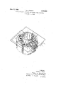
- the single figure is a perspective of my invention as it is utilized in the type of crossed-wave amplifier tube that has the cathode surrounding an inverted circular electric mode anode.
- the single figure shows part of a well known type of crossed-field amplifier tube in which a circular shaped cathode 1 surrounds a circular anode slow wave structure 2.
- a DC voltage (not shown) is normally applied between the anode and the cathode.
- the cathode is operated as a cold cathode, therefore no current is obtained from the cathode until an RF input signal causes back bombardment of the cathode. This back "bombardment causes copious secondary emission current.
- the current will ordinarily continue to flow between cathode and anode after the termination of the RF input and the tube will either oscillate or put out noise.
- crossed-field amplifiers it is not only desirable but essential for proper operation that the cathode current be cut-oil at the termination of an input pulse.
- a crossed-field amplifier tube comprising: a centrally located anode slow wave structure; a cold cathode divided into an even number of segments surrounding said anode; and transformer means to apply a pulsed voltage between alternate segments of said segmented cold cathode at the termination of an input pulse to said amplifier.
- HERMAN K. SAALBACH Primary Examiner. S. CHATMON, JR., Assistant Examiner.
Landscapes
- Amplifiers (AREA)
Description
United States Patent 3,450,938 CONTROL ELECTRODE STRUCTURE FOR CROSSED-FIELD AMPLIFIER George K. Farney, New Providence, N.J., assignor, by mesne assignments, to the United States of America as represented by the Secretary of the Army Filed Mar. 2, 1966, Ser. No. 533,126 Int. Cl. H01 25/34, 25/50, 1/20 U.S. Cl. 315-39.3 2 Claims ABSTRACT OF THE DISCLOSURE This invention relates to crossed-field amplifiers, and more particularly to a cathode-control electrode structure for crossed-field amplifier tubes.
My novel cathode-control electrode is used in crossedfield amplifiers that operate from a DC power supply with heaterless cathodes. In this type of amplifier no current is obtained from the cathode until an RF input signal causes back bombardment of the cathode. The back bombardment of the cathode causes copious secondary emission current. The current will ordinarily continue to flow between cathode and anode after the termination of the RF input, and the tube will either oscillate or put out noise.
Prior to my invention no completely satisfactory means to cut-off current in crossed-field amplifiers after termination of the RF input had been devised for crossedfield amplifiers having slow wave circuits of many sections or for crossed-field amplifiers with high peak power capabilities. My invention which basically comprises a segmented cathode provides highly elfective cut-off even for crossed-field amplifiers having extremely high peak power capabilities and for crossed-field amplifiers having slow wave circuits consisting of many sections.
Therefore, an object of my invention is to provide means to cut-01f current flow in crossed-field amplifiers at the termination of the RF input.
Another object of my invention is to provide means to cut-off current flow in crossed-field high power amplifiers at the termination of an input pulse.
A further object of my invention is to provide means to cut-ofl current flow, at the termination of the RF input, in crossed-field amplifiers having slow wave circuits of many sections.
The above mentioned and other Objects of my invention will be apparent by reference to the following detailed description and accompanying drawing in which:
The single figure is a perspective of my invention as it is utilized in the type of crossed-wave amplifier tube that has the cathode surrounding an inverted circular electric mode anode.
The single figure shows part of a well known type of crossed-field amplifier tube in which a circular shaped cathode 1 surrounds a circular anode slow wave structure 2. In this type of crossed-field amplifier a DC voltage (not shown) is normally applied between the anode and the cathode. The cathode is operated as a cold cathode, therefore no current is obtained from the cathode until an RF input signal causes back bombardment of the cathode. This back "bombardment causes copious secondary emission current. The current will ordinarily continue to flow between cathode and anode after the termination of the RF input and the tube will either oscillate or put out noise. For many applications of crossed-field amplifiers it is not only desirable but essential for proper operation that the cathode current be cut-oil at the termination of an input pulse.
Prior to my invention no method for effectively cuttingotf current flow at the termination of an input pulse had been devised for crossed-field amplifiers having high power capabilities or for crossed-field amplifiers having slow wave circuits of many sections. The prior art methods for cutting-olf current flow operate satisfactorily only if utilized in relatively low power crossed-field amplifiers having a limited number of sections in their slow wave circuits. My invention can be utilized with any type of crossed-field amplifier regardless of the power capabilities of the amplifier or the number of sections in the slow wave circuit. Referring to the figure, my invention comprises fabricating the cathode into the segments numbered 1. Cathodes of crossed-field amplifiers are normally fabricated as continuous rings or cylinders. At the termination of an RF input pulse, positive pulses are applied between alternate segments 1 of the cathode "by means of transformer 3. Any suitable coupling means other than transformer 3 may of course be used. It is obvious that the positive cathode segments immediately attract the electron current and cut-01f the cathode current flow.
While my invention is shown as being used with a particular type of crossed-field tube it is obvious that it can be utilized with any type of crossed-field tube. It should also be obvious that the cathode can be divided into more than four segments provided that an even number of segments is maintained. Up to a point a larger number of segments will enhance cut-off control. 1
I claim:
1. A crossed-field amplifier tube comprising: a centrally located anode slow wave structure; a cold cathode divided into an even number of segments surrounding said anode; and transformer means to apply a pulsed voltage between alternate segments of said segmented cold cathode at the termination of an input pulse to said amplifier.
2. A crossed-field amplifier as described in claim 1 wherein said number of segments is greater than 2.
References Cited UNITED STATES PATENTS 2,784,346 3/1957 Dodds SIS-39.63 2,832,005 4/1958 Brown 313338 X 3,305,751 2/1967 Brown I.. 31539.51 X 3,315,121 4/1967 Staats 315-39.51
HERMAN K. SAALBACH, Primary Examiner. S. CHATMON, JR., Assistant Examiner.
US. Cl. X.R. 313-338: 315-3951
Applications Claiming Priority (1)
| Application Number | Priority Date | Filing Date | Title |
|---|---|---|---|
| US53312666A | 1966-03-02 | 1966-03-02 |
Publications (1)
| Publication Number | Publication Date |
|---|---|
| US3450938A true US3450938A (en) | 1969-06-17 |
Family
ID=24124595
Family Applications (1)
| Application Number | Title | Priority Date | Filing Date |
|---|---|---|---|
| US533126A Expired - Lifetime US3450938A (en) | 1966-03-02 | 1966-03-02 | Control electrode structure for crossed-field amplifier |
Country Status (1)
| Country | Link |
|---|---|
| US (1) | US3450938A (en) |
Cited By (1)
| Publication number | Priority date | Publication date | Assignee | Title |
|---|---|---|---|---|
| US4742271A (en) * | 1985-03-25 | 1988-05-03 | Raytheon Company | Radial-gain/axial-gain crossed-field amplifier (radaxtron) |
Citations (4)
| Publication number | Priority date | Publication date | Assignee | Title |
|---|---|---|---|---|
| US2784346A (en) * | 1950-01-28 | 1957-03-05 | Rca Corp | Electron discharge device |
| US2832005A (en) * | 1951-03-06 | 1958-04-22 | Raytheon Mfg Co | Electron-discharge devices |
| US3305751A (en) * | 1962-10-26 | 1967-02-21 | Raytheon Co | Traveling wave device |
| US3315121A (en) * | 1961-04-27 | 1967-04-18 | Gen Electric | Crossed-field electric discharge device |
-
1966
- 1966-03-02 US US533126A patent/US3450938A/en not_active Expired - Lifetime
Patent Citations (4)
| Publication number | Priority date | Publication date | Assignee | Title |
|---|---|---|---|---|
| US2784346A (en) * | 1950-01-28 | 1957-03-05 | Rca Corp | Electron discharge device |
| US2832005A (en) * | 1951-03-06 | 1958-04-22 | Raytheon Mfg Co | Electron-discharge devices |
| US3315121A (en) * | 1961-04-27 | 1967-04-18 | Gen Electric | Crossed-field electric discharge device |
| US3305751A (en) * | 1962-10-26 | 1967-02-21 | Raytheon Co | Traveling wave device |
Cited By (1)
| Publication number | Priority date | Publication date | Assignee | Title |
|---|---|---|---|---|
| US4742271A (en) * | 1985-03-25 | 1988-05-03 | Raytheon Company | Radial-gain/axial-gain crossed-field amplifier (radaxtron) |
Similar Documents
| Publication | Publication Date | Title |
|---|---|---|
| GB578655A (en) | Improvements in or relating to high frequency electron discharge systems | |
| US2680209A (en) | High-frequency apparatus | |
| GB495531A (en) | Cathode ray device | |
| GB1039833A (en) | Crossed field tube | |
| US3346766A (en) | Microwave cold cathode magnetron with internal magnet | |
| US2800603A (en) | Traveling wave electron discharge devices | |
| US3450938A (en) | Control electrode structure for crossed-field amplifier | |
| GB643655A (en) | Improvements in or relating to magnetron electron discharge devices | |
| GB981743A (en) | Improvements in electron guns | |
| GB715389A (en) | Improvements in electron discharge devices | |
| GB1038258A (en) | Electron discharge microwave tubes | |
| GB708216A (en) | Improvements in and relating to magnetrons | |
| US2955229A (en) | Secondary emission suppression in electron beam tubes | |
| GB539661A (en) | Improvements in or relating to thermionic discharge devices | |
| US2207356A (en) | Electron discharge apparatus | |
| US2762944A (en) | Magnetic triode | |
| US3450932A (en) | Reentrant beam crossed-field amplifier with electronic feedback inhibiting filter | |
| US3803442A (en) | Travelling wave tube | |
| US2685046A (en) | Magnetron | |
| US2280228A (en) | Electron beam discharge device | |
| Hoover | Advances in the techniques and applications of very-high-power grid-controlled tubes | |
| GB959207A (en) | Improvements in velocity-modulated electron-beam tubes | |
| GB1009394A (en) | Improvements in electron-beam tubes for parametric amplification | |
| GB618364A (en) | Improvements in or relating to electron discharge devices | |
| GB1070134A (en) | An ultrahigh-frequency disc-sealed thermionic tube |