US3346176A - Rotary mechanism including abradable lubricating and sealing means - Google Patents
Rotary mechanism including abradable lubricating and sealing means Download PDFInfo
- Publication number
- US3346176A US3346176A US494356A US49435665A US3346176A US 3346176 A US3346176 A US 3346176A US 494356 A US494356 A US 494356A US 49435665 A US49435665 A US 49435665A US 3346176 A US3346176 A US 3346176A
- Authority
- US
- United States
- Prior art keywords
- pump
- internal
- peripheral wall
- air
- working chamber
- Prior art date
- Legal status (The legal status is an assumption and is not a legal conclusion. Google has not performed a legal analysis and makes no representation as to the accuracy of the status listed.)
- Expired - Lifetime
Links
Images

Classifications
-
- F—MECHANICAL ENGINEERING; LIGHTING; HEATING; WEAPONS; BLASTING
- F04—POSITIVE - DISPLACEMENT MACHINES FOR LIQUIDS; PUMPS FOR LIQUIDS OR ELASTIC FLUIDS
- F04C—ROTARY-PISTON, OR OSCILLATING-PISTON, POSITIVE-DISPLACEMENT MACHINES FOR LIQUIDS; ROTARY-PISTON, OR OSCILLATING-PISTON, POSITIVE-DISPLACEMENT PUMPS
- F04C27/00—Sealing arrangements in rotary-piston pumps specially adapted for elastic fluids
- F04C27/001—Radial sealings for working fluid
-
- F—MECHANICAL ENGINEERING; LIGHTING; HEATING; WEAPONS; BLASTING
- F01—MACHINES OR ENGINES IN GENERAL; ENGINE PLANTS IN GENERAL; STEAM ENGINES
- F01C—ROTARY-PISTON OR OSCILLATING-PISTON MACHINES OR ENGINES
- F01C21/00—Component parts, details or accessories not provided for in groups F01C1/00 - F01C20/00
- F01C21/10—Outer members for co-operation with rotary pistons; Casings
- F01C21/104—Stators; Members defining the outer boundaries of the working chamber
- F01C21/106—Stators; Members defining the outer boundaries of the working chamber with a radial surface, e.g. cam rings
-
- F—MECHANICAL ENGINEERING; LIGHTING; HEATING; WEAPONS; BLASTING
- F01—MACHINES OR ENGINES IN GENERAL; ENGINE PLANTS IN GENERAL; STEAM ENGINES
- F01N—GAS-FLOW SILENCERS OR EXHAUST APPARATUS FOR MACHINES OR ENGINES IN GENERAL; GAS-FLOW SILENCERS OR EXHAUST APPARATUS FOR INTERNAL-COMBUSTION ENGINES
- F01N3/00—Exhaust or silencing apparatus having means for purifying, rendering innocuous, or otherwise treating exhaust
- F01N3/08—Exhaust or silencing apparatus having means for purifying, rendering innocuous, or otherwise treating exhaust for rendering innocuous
- F01N3/10—Exhaust or silencing apparatus having means for purifying, rendering innocuous, or otherwise treating exhaust for rendering innocuous by thermal or catalytic conversion of noxious components of exhaust
- F01N3/24—Exhaust or silencing apparatus having means for purifying, rendering innocuous, or otherwise treating exhaust for rendering innocuous by thermal or catalytic conversion of noxious components of exhaust characterised by constructional aspects of converting apparatus
- F01N3/30—Arrangements for supply of additional air
- F01N3/32—Arrangements for supply of additional air using air pump
-
- F—MECHANICAL ENGINEERING; LIGHTING; HEATING; WEAPONS; BLASTING
- F02—COMBUSTION ENGINES; HOT-GAS OR COMBUSTION-PRODUCT ENGINE PLANTS
- F02B—INTERNAL-COMBUSTION PISTON ENGINES; COMBUSTION ENGINES IN GENERAL
- F02B33/00—Engines characterised by provision of pumps for charging or scavenging
-
- F—MECHANICAL ENGINEERING; LIGHTING; HEATING; WEAPONS; BLASTING
- F04—POSITIVE - DISPLACEMENT MACHINES FOR LIQUIDS; PUMPS FOR LIQUIDS OR ELASTIC FLUIDS
- F04C—ROTARY-PISTON, OR OSCILLATING-PISTON, POSITIVE-DISPLACEMENT MACHINES FOR LIQUIDS; ROTARY-PISTON, OR OSCILLATING-PISTON, POSITIVE-DISPLACEMENT PUMPS
- F04C2/00—Rotary-piston machines or pumps
- F04C2/30—Rotary-piston machines or pumps having the characteristics covered by two or more groups F04C2/02, F04C2/08, F04C2/22, F04C2/24 or having the characteristics covered by one of these groups together with some other type of movement between co-operating members
- F04C2/34—Rotary-piston machines or pumps having the characteristics covered by two or more groups F04C2/02, F04C2/08, F04C2/22, F04C2/24 or having the characteristics covered by one of these groups together with some other type of movement between co-operating members having the movement defined in groups F04C2/08 or F04C2/22 and relative reciprocation between the co-operating members
- F04C2/344—Rotary-piston machines or pumps having the characteristics covered by two or more groups F04C2/02, F04C2/08, F04C2/22, F04C2/24 or having the characteristics covered by one of these groups together with some other type of movement between co-operating members having the movement defined in groups F04C2/08 or F04C2/22 and relative reciprocation between the co-operating members with vanes reciprocating with respect to the inner member
- F04C2/352—Rotary-piston machines or pumps having the characteristics covered by two or more groups F04C2/02, F04C2/08, F04C2/22, F04C2/24 or having the characteristics covered by one of these groups together with some other type of movement between co-operating members having the movement defined in groups F04C2/08 or F04C2/22 and relative reciprocation between the co-operating members with vanes reciprocating with respect to the inner member the vanes being pivoted on the axis of the outer member
-
- F—MECHANICAL ENGINEERING; LIGHTING; HEATING; WEAPONS; BLASTING
- F02—COMBUSTION ENGINES; HOT-GAS OR COMBUSTION-PRODUCT ENGINE PLANTS
- F02M—SUPPLYING COMBUSTION ENGINES IN GENERAL WITH COMBUSTIBLE MIXTURES OR CONSTITUENTS THEREOF
- F02M2700/00—Supplying, feeding or preparing air, fuel, fuel air mixtures or auxiliary fluids for a combustion engine; Use of exhaust gas; Compressors for piston engines
- F02M2700/33—Compressors for piston combustion engines
-
- Y—GENERAL TAGGING OF NEW TECHNOLOGICAL DEVELOPMENTS; GENERAL TAGGING OF CROSS-SECTIONAL TECHNOLOGIES SPANNING OVER SEVERAL SECTIONS OF THE IPC; TECHNICAL SUBJECTS COVERED BY FORMER USPC CROSS-REFERENCE ART COLLECTIONS [XRACs] AND DIGESTS
- Y02—TECHNOLOGIES OR APPLICATIONS FOR MITIGATION OR ADAPTATION AGAINST CLIMATE CHANGE
- Y02T—CLIMATE CHANGE MITIGATION TECHNOLOGIES RELATED TO TRANSPORTATION
- Y02T10/00—Road transport of goods or passengers
- Y02T10/10—Internal combustion engine [ICE] based vehicles
- Y02T10/12—Improving ICE efficiencies
-
- Y—GENERAL TAGGING OF NEW TECHNOLOGICAL DEVELOPMENTS; GENERAL TAGGING OF CROSS-SECTIONAL TECHNOLOGIES SPANNING OVER SEVERAL SECTIONS OF THE IPC; TECHNICAL SUBJECTS COVERED BY FORMER USPC CROSS-REFERENCE ART COLLECTIONS [XRACs] AND DIGESTS
- Y10—TECHNICAL SUBJECTS COVERED BY FORMER USPC
- Y10S—TECHNICAL SUBJECTS COVERED BY FORMER USPC CROSS-REFERENCE ART COLLECTIONS [XRACs] AND DIGESTS
- Y10S417/00—Pumps
- Y10S417/01—Materials digest
Definitions
- this coating material by a plasma spray process.
- the powdered material is thoroughly mixed and subsequently transported by a carrier gas into the inert hot gas stream of the plasma torch.
- a carrier gas into the inert hot gas stream of the plasma torch.
- the maximum particle size of the molybdenum disulfide be 300 mesh
- of the polyethylene be 200 mesh
- of the chlorinated polyether be 200 mesh.
- a suitable carrier gas and inert gas is argon.
Landscapes
- Engineering & Computer Science (AREA)
- Mechanical Engineering (AREA)
- General Engineering & Computer Science (AREA)
- Chemical & Material Sciences (AREA)
- Combustion & Propulsion (AREA)
- Chemical Kinetics & Catalysis (AREA)
- Health & Medical Sciences (AREA)
- Toxicology (AREA)
- Applications Or Details Of Rotary Compressors (AREA)
- Application Of Or Painting With Fluid Materials (AREA)
- Structures Of Non-Positive Displacement Pumps (AREA)
Description
Oct. 10, 1967 L. ROTARY MECHANI INCLUDING ABRADABLE LUBHICATINGAND SEALING MEANS Filed Oct. l1, 1965 2 Sheets-Sheet l Z 'in Oct. 10, 1967 1 E. ROTARY- CHANISM'INCLUDING ABR BLE vLUB I ATING AND SEALING ME 2 Sheets-Sheet. 2
Filed Oct. ll, 1965 IN VENTO/2.
Ezop l 3,346,176 y United States Patent O 3,346,176 ROTARY MECHANISM INCLUDING ABRADABLE LUBRICATING AND SEALING MEANS L. Eugene Ezop, Saginaw, Mich., assignor to General Motors Corporation, Detroit, Mich., a corporation of Delaware Filed ct. 11, 1965, Ser. No. 494,356 8 Claims. (Cl. 230-157) This invention relates to means forV sealing a Working chamber of a rotary mechanism such as a pump and for reducing frictional losses in the rotary mechanism. More particularly, this invention relates to an abradable composition which is advantageously applied between relatively moving parts within an air pump to increase the mechanical and volumetric efficiency of the pump.
For the past several years, a great deal of emphasis has been placed on development of an arrangement for reducing the proportion of unburned constituents, such as unburned hydrocarbons and carbon monoxide, in the exhaust gases emitted fromv automotive engines. vOne of the most effective arrangements so far developed is the air injector reactor system. In this system, an engine driven pump injects a stream 0f air into the flow of hot exhaust gases at a point just downstream of the engine combustion chamber exhaust valve. At this point, the exhaust gases are extremely hot and ignite to combine with the injected air providing more complete combustion of the otherwise unburned hydrocarbons and carbon monoxide.
The requirements imposed upon the pump used to supply the air in the air injector reactor system are quite stringent; for example, the pressure and the rate of the air iiow from the pump must -be controlled over a wide range of engine speeds for optimum reduction of exhaust emissions. It has been discovered that a semi-articulated vane pump is a very efficient and economical type for such an application.
Such a pump, however, has many moving `parts each of which provides a source of friction tending to reduce the eiiiciency of operation. These frictional losses cannot be overcome by oils and greases used in conventional lubricating systems because during operation those lubricants would be gradually vaporized and emitted from the pump. The pump would then become another source for vunburned hydrocarbons. Furthermore, while the frictional losses can be overcome by designing the pump with clearances between surfaces at which there is relative motion, the rotor and the Stripping land, for example, any gain obtained in this manner isY offset by a loss in volumetric efficiency.
This invention provides a coating material for an articulated vane air pump which furnishes lubrication, will 'absorb some foreign particles entering the pump to prevent damage to the air pump components, is selfehealing and furnishes a means of fabricating a pump with 0 clearance between the rotor and the stripping land. This invention further provides a coating material which is strongly adhering to the surface of those pump components to which it is applied.
These and other objects and advantages are accomplished by applying a hot mixture comprised of 70 to 90% by weight molybdenum disulfide, 2 to 30% by weight of a suitable chlorinated polyether, and 0 to 28% parts by weight polyethylene to an appropriate pump component Surface which has been preheated to about 300 F. A layer is deposited having a thickness of at least 0.01" and which upon cooling to room temperature hardens to a -highly serviceable abradable surface coating.
Of course, it is known in the art that molybdenum disuliide is a useful 'lubricating agent. For example, Weiss,
'3,072,068 and 3,086,476 teaches the utility of a M052 impregnated grease on ya felt-like material as applied between a stator and rotor portion of a pump. However, I have found the Weiss type means of lubrication unsuitable for the air injector application. In such an application, it is expensive and insuiiicient in sealing characteristics and durability. The lack of a suitable prior art lubricant and seal composition has lead to my invention.
Although this invention is plainly illustrated and described with reference to a semi-articulated vane pump, those skilled in the art will appreciate the utility of such a lubricating and sealing material in many other types of rotary mechanisms.
The details as well as other objects and advantages of this invention appear in the following description and in the drawings in which:
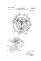
FIGURE 1 illustrates an internal combustion engine provided with an air injector reactor system;
FIGURE 2 is -a vertical section view through t-he semiartic'ulated vane pump along the line 2 2 of FIGURE l illustrating the location of the lubricating and sealing coating;
FIGURE 3 is a sectional view along line 3-3 of FIG- ure 2;
FIGURE 4 is an enlarged fragmented and somewhat distorted view of FIGURE 3 more clearly illustrating the subject coating.
Referring first to FIGURE 1, an internal combustion engine E is provided with a carburetor C and an `air lter F. An air pump 10 is secured to engine E by a bracket 12 and is driven by engine E through a Ibelt 14. Air pump 10 has an inlet hose 16 through which clean air is drawn from air lter F and an outlet hose 18 through which air is delivered to an air 4manifold 20. Air manifold 20 has a series of injection tubes 22 through which air is injected into the stream of exhaust gases adjacent the combustion chamber exhaust valves.
Referringy now to FIGURES 2 and 3, air pump 10 has a concave housing 24 closed by a cover plate 26. As shown in FIGURE 3, the interior wall 2S of housing 24 is of substantially circular cross section. A rotor 30, disposed in housing 24 von an axis eccentric to the axis of the housing, has an exterior wall 32 of circular cross section which is tangent the interior w-all 28 of housing 24 at its lower-most point to provide a stripping land 34. The stripping land has an arcuate surface 35 whi-ch is slidingly ,and sealingly engageable by said rotor 30.
The interior wall 28 is recessed on opposite sides of the stripping land 34 to -form an inlet area 36 and outlet area 38. Inlet and outlet areas 36 and 38 extend axially the entire length of the pum-p and are provided at one end with fittings 40 to which the inlet and outlet hoses 16 and 18 are secured.
A particular advantage is achieved by locating the inlet and outlet areas 36 and 3S at the bottom of the pump since any moisture tending to condense in the pump will drain into these areas. Should the pump be mounted in an inverted position, the moisture would drain to another portion of the housing and would interfere with pump operation were it to freeze.
A shaft 42 is secured in cover plate 26 and extends into the space enclosed by the housing 24 concentrically with the interior ywall 28. Three pairs of bearing supporting Ahubs 44 are positioned on shaft 42, each pair supporting yair Afrom inlet 36 and direct a pressurized stream of air through outlet 38. Stripping land 34 prevents leakage of air between outlet 38 and inlet 36 which would otherwise reduce the efficiency of the pump.
As shown in FIGURE 3, the interior wall 28 of housing 24 is provided with a notch 56 leading from the inlet area 36 to the working chamber 54 and a notch 58 leading from the working chamber 54 to the outlet area 38. Notches 56 and 58 prevent a sudden change in pressure as vanes 46 pass the inlet and outlet areas 36 and 38.
Each vane 46 is sealed in its corresponding slot 48 in rotor 30 by a pair of sealing strips 60 and 62 positioned in grooves 64 opening into the slots 48. Referring to FIG- URE 3, it will be appreciated that as rotor 30 is driven clockwise by belt 14, sealing strips 60 drive vanes 46. Sealing strips 62 are backed by conventional leaf sp-rings 66 which bias strips 62 against vanes 46. Sealing strips 60 and 62 thus cooperate to prevent air flow from the working chamber 54 through slots 48 into the interior portion of rotor 30.
In this air pump a coating 68 is applied to the arcuate surface 35 of the stripping land 34. The coating 68 provides lubrication to reduce friction losses between the rotor exterior wall 32, the vanes 46 and the stripping land arcuate surface 35. It also provides sealing means to prevent the flow of air between the outlet area 38 and the inlet area 36. The composition of the coating 68 is comprised by weight of 70 to 90% of molybdenum disulfide, to 28% by weight polyethylene, and 2 to 30% by weight of the chlorinated polyether formed by polymerizing 3,3- bis-(chloromethyl) oxetane and having a molecular weight in the range of about 250,000 to 400,000. This material and the molybdenum disulfide and polyethylene are well known commercially available materials.
I have found it preferable to apply this coating material by a plasma spray process. The powdered material is thoroughly mixed and subsequently transported by a carrier gas into the inert hot gas stream of the plasma torch. When the powder mixture is applied in this way, it is preferable that the maximum particle size of the molybdenum disulfide be 300 mesh, of the polyethylene be 200 mesh, and of the chlorinated polyether be 200 mesh. A suitable carrier gas and inert gas is argon. A specific coating composition which I have found to be particularly advantageous is comprised by weight of 76.14% MOSZ, 19.10% polyethylene, and 4.76% Penton, a chlorinated polyether formed by polymerizing 3,3-bis- (chloromethyl) oxetane and having a molecular weight in the range of about 250,000' to 400,000. Prior to the application of the coating composition, the land 34 or other suitable surface is preheated to a temperature of 300 F. The surface should preferably be free of all oil. To this end it may be desirable to blast the surface with 120 mesh quartz. The coating material is then sprayed upon the surface with a back and forth motion which results in a reasonably uniform coating. The surface may be water cooled after spraying. The coating may be damaged if it contacts any solid object before it is cooled to 150 F. A minimum thickness of 0.01 inch is preferred in this embodiment.
The use of my coating composition permits manufacture of pump components to less restrictive tolerances. The coating is abradable and after a short run-in period will be shaped to form an excellent sealing member. The molybdenum disulfide in the formulation provides lubricating properties to increase the mechanical eiiiciency of the pump and the close seal effected by the abraded coating prevents the leakage of air between the intake and exhaust chambers, thus increasing the volumetric eiiiciency of the pump. The abradable characteristic of the coating also allows for variation in component tolerances due to temperature changes. In addition, solid particles entering the pump tend to imbed in the coating or erode the coating slightly rather than ycause the pump to seize.
I have found that the coating is somewhat self-healing after it has been eroded by foreign particles.
One may depart somewhat from the process outlined above where all the components are mixed before application to the hot pump surface. In some circumstances it may be desirable to vary the coating composition throughout its thickness. For example, under some circumstances it may be desirable to increase the plastic composition at the metal surface to which the coating is bonded and increase the molybdenum disulfide concentration at the air surface. In this case two or more layers of different composition may be applied. While the composition may vary throughout the cross section, I have found it preferable to keep the over-all composition within the limits set forth above. Although the need for such a coating was first realized in the development of this air pump, it is apparent to anyone skilled in the art that such a useful abradable coating could find application in any of a vast number of rotary mechanisms.
While this invention has been described in terms of certain preferred embodiments, it is to be understood that other applications would be apparent to those skilled inthe are and are within the scope of the invention as defined by the following claims.
It is claimed:
1. In a rotary mechanism, a hollow outer body having an internal peripheral wall; an internal body positioned within said outer body and having an external peripheral wall, portions of which are radially spaced from said internal peripheral wall to form a working chamber, said inner and outer bodies each having a pair of axially spaced end walls respectively connected by said external and internal peripheral walls, said end walls cooperating to enclose each end of said working chamber, said inner and outer bodies being relatively rotatable and including means to vary the pressure in said working chamber upon relative rotation; the axially extending portion of said internal peripheral wall most closely adjacent said internal body having an arcuate surface slidingly and sealingly engageable by said internal body to form a stripping land; and an abradable coating material strongly adhering to said stripping land comprised of to 90% by weight molybdenum disulfide, 0% to 28% polyethylene, and 2% to 30% of the chlorinated polyether formed by polymerizing 3,3-bis-(chloromethyl) oxetane and having a molecular weight in the range of about 250,000 to 400,000.
2. A rotary mechanism as in claim 1 wherein said abradable coating material is comprised by weight of 76.14% molybdenum disulfide, 19.10% polyethylene, and 4.76% of the chlorinated polyether formed by polymerizing 3,3-bis-(chloromethyl) oxetane and having a molecular weight in the range of about 250,000 to 400,000.
3. A rotary pump comprising a housing having axially spaced end walls connected by a cylindrical internal peripheral wall forming a cavity; a rotor positioned within said cavity and having axial extensions supporting each end of said rotor in said housing for rotations relative thereto, said rotor having an axis parallel toand spaced from the axis of said cavity and having a cylindrical external peripheral wall, portions of which are radially spaced from said internal wall to form a working chamber, the axially extending portion of said internal wall most closely adjacent said rotor having an arcuate surface slidingly and sealingly engageable by said rotor to form a stripping land; and an abradable coating strongly adhering to said stripping land comprised of 70% to 90% by weight molybdenum disulfide, 0% to 28% by weight polyethylene, and 2% to 30% by weight of the chlorinated polyether formed by polymerizing 3,3-bis-(chloromethyl) oxetane and having a molecular weight in the range of about 250,000 to 400,000.
4. A rotary pump as in claim 3 wherein said abradable coating material is comprised by weight of 76.14% molybdenum disulfide', 19.10% polyethylene and 4.76% of the chlorinated polyether formed by polymerizing 3,3-
bis(chloromethyl) oxetane and having a molecular Weight in the range of about 250,000 to 400,000.
5. An air pump adapted yfor use in a system for supplyin-g air to the stream of hot exhaust gases emitted from an internal combustion engine, said air pump comprising a housing having axially spaced end Walls connected by a horizontally extending cylindrical internal peripheral Wall forming a cavity, a hollow rotor positioned Within said cavity and having a horizontal axis parallel to and spaced from the axis of said cavity, said rotor having end walls adjacent the housing end walls and having a drive shaft concentric with said rotor extending axially from one end wall of said rotor through one end Wall of said housing, said drive shaft being adapted to support and rotate said rotor Within said housing, said rotor having cylindrical external peripheral Wall portions of which are radially spaced from said internal Wall to form a crescentshaped Working chamber, said housing internal Wall having an axially extending portion tangent the lowermost portion of said rotor and forming a stripping land, said internal wall having ya pair of recesses adjacent and on opposite sides of said stripping land forming an inlet and an outlet for said Working chamber, a mounting shaft secured in the other end wall of said housing and extending concentrically into sai-d cavity, said rotor surrounding said mounting shaft, three radially extending vanes mounted for rotation upon said mounting shaft, said rotor having sealed slots through which said vanes extend into said working chamber, said rotor and vanes being adapted upon rotation to direct an air stream through said working chamber from said inlet to said outlet and to increase the pressure in said air stream, said internal Wall having notches leading from the recess forming the inlet and leading into the recess forming the outlet to achieve a gradual increase in the air stream pressure, and an abradable coating material strongly adhering to sai-d stripping land comprised of 70% to 90% by Weight molybdenum disulfide, to 28% polyethylene, and 2% to 30% of the chlorinated polyether formed by polymerizing 6 3,3-bis-(chloromethyl) oxetane and having a molecular Weight in the range of about 250,000 to 400,000.
6. An air pump as in claim 5 wherein said abradable coating material is comprised by Weight of 76.14% molybdenum disulfide, 19.10% polyethylene, and 4.76% of the chlorinated polyether formed by polymerizing 3,3- bis-(chloromethyl) oxetane and having a molecular Weight in the range of about 250,000 to 400,000.
7. An abradable surface coating operable as a sealing and lubricating means between a stator portion and a rotor portion of a rotary machine, said coating comprising by Weight lto 90% molybdenum disulfide, 2% to 30% of the chlorinated polyether formed by polymerizing 3,3bis(chloromethy1)A oxetane and having a molecular Weight in the range of about 250,000 to 400,000 and 0% to 28% polyethylene.
8. An abradable surface coating operable as a sealing and lubricating means between a stator portion and a rotor portion of a rotary air pump, said coating comprising by Weight 76.14% molybdenum disulde, 19.10% polyethylene and 4.76% 4of the chlorinated p-olyether formed by polymerizing 3,3-bis-(chloromethy1) oxetane and having a molecular Weight in the ran-ge of about 250,000 to 400,000.
References Cited UNITED STATES PATENTS Re. 24,932 1/1961 Davey 103-216 2,492,935 12/ 1949 McCulloch et al. 230-141 2,519,557 8/1950 Flanagan 230-141 2,519,588 8/7950 McCulloch 230-141 2,715,617 8/1955 White 103-114 2,754,050 7/ 1956 Wellington 230-141 3,072,068 1/ 1963 Weiss 10S-144 3,086,476 4/ 1963 Weiss 103--216 DONLEY I STOCKING, Primary Examiner. WILBUR I. GOODLIN, Examiner.
Claims (1)
1. IN A ROTARY MECHANISM, A HOLLOW OUTER BODY HAVING AN INTERNAL PERIPHERAL WALL; AN INTERNAL BODY POSITIONED WITHIN SAID OUTER BODY AND HAVING AN EXTERNAL PERIPHERAL WALL, PORTIONS OF WHICH ARE RADIALLY SPACED FROM SAID INTERNAL PERIPHERAL WALL TO FORM A WORKING CHAMBER, SAID INNER AND OUTER BODIES EACH HAVING A PAIR OF AXIALLY SPACED END WALLS RESPECTIVELY CONNECTED BY SAID EXTERNAL AND INTERNAL PERIPHERAL WALLS, SAID END WALLS COOPERATING TO ENCLOSE EACH END OF SAID WORKING CHAMBER, SAID INNER AND OUTER BODIES BEING RELATIVELY ROTATABLE AND INCLUDING MEANS TO VARY THE PRESSURE IN SAID WORKING CHAMBER UPON RELATIVE ROTATION; THE AXIALLY EXTENDING PORTION OF SAID INTERNAL PERIPHERAL WALL MOST CLOSELY ADJACENT SAID INTERNAL BODY HAVING AN ARCUATE SURFACE SLIDINGLY AND SEALINGLY ENGAGEABLE BY SAID INTERNAL BODY TO FORM A STRIPPING LAND; AND AN ABRADABLE COATING MATERIAL STRONGLY ADHERING TO SAID STRIPPING LAND COMPRISED OF 70% TO 90% BY WEIGHT MOLYBDENUM DISULFIDE, 0% TO 28% POLYETHYLENE, AND 2% TO 30% OF THE CHLORINATED POLYETHER FORMED BY POLYMERIZING 3,3-BIS-(CHLOROMETHYL) OXETHANE AND HAVING A MOLECULAR WEIGHT IN THE RANGE OF ABOUT 250,000 TO 400,000.
Priority Applications (3)
| Application Number | Priority Date | Filing Date | Title |
|---|---|---|---|
| US494356A US3346176A (en) | 1965-10-11 | 1965-10-11 | Rotary mechanism including abradable lubricating and sealing means |
| DE1553063A DE1553063C3 (en) | 1965-10-11 | 1966-09-27 | Sealing strip on the delivery chamber wall of a rotary piston compressor |
| GB43500/66A GB1110924A (en) | 1965-10-11 | 1966-09-29 | Rotary pumps or motors |
Applications Claiming Priority (1)
| Application Number | Priority Date | Filing Date | Title |
|---|---|---|---|
| US494356A US3346176A (en) | 1965-10-11 | 1965-10-11 | Rotary mechanism including abradable lubricating and sealing means |
Publications (1)
| Publication Number | Publication Date |
|---|---|
| US3346176A true US3346176A (en) | 1967-10-10 |
Family
ID=23964145
Family Applications (1)
| Application Number | Title | Priority Date | Filing Date |
|---|---|---|---|
| US494356A Expired - Lifetime US3346176A (en) | 1965-10-11 | 1965-10-11 | Rotary mechanism including abradable lubricating and sealing means |
Country Status (3)
| Country | Link |
|---|---|
| US (1) | US3346176A (en) |
| DE (1) | DE1553063C3 (en) |
| GB (1) | GB1110924A (en) |
Cited By (8)
| Publication number | Priority date | Publication date | Assignee | Title |
|---|---|---|---|---|
| US3419208A (en) * | 1966-06-09 | 1968-12-31 | Gen Motors Corp | Fluid flow control mechanism |
| US3437265A (en) * | 1968-06-03 | 1969-04-08 | Gen Motors Corp | Vane-type rotary mechanism |
| US3632240A (en) * | 1968-11-22 | 1972-01-04 | Bosch Gmbh Robert | Wear-reducing arrangement for hydraulic gear apparatus |
| DE2223087A1 (en) * | 1972-05-12 | 1973-12-13 | Bosch Gmbh Robert | FLOW CELL COMPRESSOR |
| JPS5028304U (en) * | 1973-07-06 | 1975-04-01 | ||
| US4618319A (en) * | 1984-11-19 | 1986-10-21 | Robert Bosch Gmbh | Vane-type compressor having resilient slot seals |
| EP0568493A3 (en) * | 1992-04-01 | 1993-12-15 | Lindau Tech Forsch & Entw Gmbh | Internal axis rotary piston machine |
| CN109416045A (en) * | 2016-07-08 | 2019-03-01 | 雀巢产品技术援助有限公司 | Rotary Compressor device |
Families Citing this family (4)
| Publication number | Priority date | Publication date | Assignee | Title |
|---|---|---|---|---|
| US4072451A (en) * | 1976-10-12 | 1978-02-07 | Sperry Rand Corporation | Power transmission |
| DE8424731U1 (en) * | 1984-08-21 | 1985-12-19 | Robert Bosch Gmbh, 7000 Stuttgart | Gear machine |
| BE1006323A3 (en) * | 1992-11-03 | 1994-07-19 | Eelbode Hugo | Rotating, volumetric compressor/motor with centrally controlled blades |
| DE102010042455A1 (en) * | 2010-10-14 | 2012-04-19 | Robert Bosch Gmbh | Gear pump for conveying a liquid |
Citations (8)
| Publication number | Priority date | Publication date | Assignee | Title |
|---|---|---|---|---|
| US2492935A (en) * | 1943-11-22 | 1949-12-27 | Borg Warner | Rotary blower with abrading rotor ends and abradable casing sealing ridges |
| US2519588A (en) * | 1943-12-24 | 1950-08-22 | Borg Warner | Pump housing |
| US2519557A (en) * | 1943-08-11 | 1950-08-22 | Bendix Aviat Corp | Means for preventing seizure of moving parts |
| US2715617A (en) * | 1954-07-29 | 1955-08-16 | Hobart S White | Bearing compositions containing polytetrafluoroethylene |
| US2754050A (en) * | 1950-04-22 | 1956-07-10 | Gen Motors Corp | Rotary blower |
| USRE24932E (en) * | 1961-01-31 | Light metal vane for rotary compressors | ||
| US3072068A (en) * | 1958-10-13 | 1963-01-08 | American Thermocatalytic Corp | Vane pumps |
| US3086476A (en) * | 1959-09-17 | 1963-04-23 | American Thermocatalytic Corp | Rotary pumps |
-
1965
- 1965-10-11 US US494356A patent/US3346176A/en not_active Expired - Lifetime
-
1966
- 1966-09-27 DE DE1553063A patent/DE1553063C3/en not_active Expired
- 1966-09-29 GB GB43500/66A patent/GB1110924A/en not_active Expired
Patent Citations (8)
| Publication number | Priority date | Publication date | Assignee | Title |
|---|---|---|---|---|
| USRE24932E (en) * | 1961-01-31 | Light metal vane for rotary compressors | ||
| US2519557A (en) * | 1943-08-11 | 1950-08-22 | Bendix Aviat Corp | Means for preventing seizure of moving parts |
| US2492935A (en) * | 1943-11-22 | 1949-12-27 | Borg Warner | Rotary blower with abrading rotor ends and abradable casing sealing ridges |
| US2519588A (en) * | 1943-12-24 | 1950-08-22 | Borg Warner | Pump housing |
| US2754050A (en) * | 1950-04-22 | 1956-07-10 | Gen Motors Corp | Rotary blower |
| US2715617A (en) * | 1954-07-29 | 1955-08-16 | Hobart S White | Bearing compositions containing polytetrafluoroethylene |
| US3072068A (en) * | 1958-10-13 | 1963-01-08 | American Thermocatalytic Corp | Vane pumps |
| US3086476A (en) * | 1959-09-17 | 1963-04-23 | American Thermocatalytic Corp | Rotary pumps |
Cited By (11)
| Publication number | Priority date | Publication date | Assignee | Title |
|---|---|---|---|---|
| US3419208A (en) * | 1966-06-09 | 1968-12-31 | Gen Motors Corp | Fluid flow control mechanism |
| US3437265A (en) * | 1968-06-03 | 1969-04-08 | Gen Motors Corp | Vane-type rotary mechanism |
| US3632240A (en) * | 1968-11-22 | 1972-01-04 | Bosch Gmbh Robert | Wear-reducing arrangement for hydraulic gear apparatus |
| DE2223087A1 (en) * | 1972-05-12 | 1973-12-13 | Bosch Gmbh Robert | FLOW CELL COMPRESSOR |
| JPS5028304U (en) * | 1973-07-06 | 1975-04-01 | ||
| US4618319A (en) * | 1984-11-19 | 1986-10-21 | Robert Bosch Gmbh | Vane-type compressor having resilient slot seals |
| EP0568493A3 (en) * | 1992-04-01 | 1993-12-15 | Lindau Tech Forsch & Entw Gmbh | Internal axis rotary piston machine |
| CN109416045A (en) * | 2016-07-08 | 2019-03-01 | 雀巢产品技术援助有限公司 | Rotary Compressor device |
| US20190309752A1 (en) * | 2016-07-08 | 2019-10-10 | Nestec S.A. | Rotary Compressor Arrangement |
| US10876530B2 (en) * | 2016-07-08 | 2020-12-29 | Societe Des Produits Nestle S.A. | Rotary compressor arrangement |
| CN109416045B (en) * | 2016-07-08 | 2021-04-02 | 雀巢产品有限公司 | Rotary compressor unit |
Also Published As
| Publication number | Publication date |
|---|---|
| DE1553063B2 (en) | 1974-02-07 |
| GB1110924A (en) | 1968-04-24 |
| DE1553063C3 (en) | 1974-08-29 |
| DE1553063A1 (en) | 1970-07-16 |
Similar Documents
| Publication | Publication Date | Title |
|---|---|---|
| US3346176A (en) | Rotary mechanism including abradable lubricating and sealing means | |
| EP0705979B1 (en) | Efficiency enhanced fluid pump or compressor | |
| US4012180A (en) | Rotary compressor with labyrinth sealing | |
| US4018548A (en) | Rotary trochoidal compressor | |
| US4519755A (en) | Gerotor vacuum pump | |
| US3091386A (en) | Cooling system for rotary mechanisms | |
| JPS5810190A (en) | Vane type compressor | |
| US3456624A (en) | Seal construction for rotary combustion engine | |
| US3333763A (en) | Sealing arrangement for rotary engines | |
| US2979042A (en) | Seal vent arrangement for rotating combustion engines | |
| US4137019A (en) | Rotary piston machine | |
| US4008015A (en) | Rotor-stator gear set | |
| US3356292A (en) | Bearing and sealing means | |
| GB1358002A (en) | Planetary piston internal combustion engines | |
| US3814555A (en) | Rotary engine gas seal lubrication system | |
| US3771902A (en) | Rotary compressor | |
| US3671146A (en) | Fluid energy machine | |
| GB994957A (en) | Improvements relating to rotary-piston internal combustion engines | |
| US3781147A (en) | Sealing device for a rotary internal combustion engine | |
| US3844691A (en) | Lubricant supply system for rotary piston engine | |
| US3868929A (en) | Lubricating oil supply system for rotary engine | |
| US9334795B2 (en) | Rotary internal combustion engine with static oil seal | |
| US3809021A (en) | Rotary-piston injection-type internal combustion engine | |
| US3545901A (en) | Rotor for rotary piston engines | |
| US3693608A (en) | End wall construction for a rotary piston internal combusion engine |