US3169655A - Caps for containers, bottles or the like - Google Patents
Caps for containers, bottles or the like Download PDFInfo
- Publication number
- US3169655A US3169655A US207603A US20760362A US3169655A US 3169655 A US3169655 A US 3169655A US 207603 A US207603 A US 207603A US 20760362 A US20760362 A US 20760362A US 3169655 A US3169655 A US 3169655A
- Authority
- US
- United States
- Prior art keywords
- cap
- container
- bottle
- caps
- flange
- Prior art date
- Legal status (The legal status is an assumption and is not a legal conclusion. Google has not performed a legal analysis and makes no representation as to the accuracy of the status listed.)
- Expired - Lifetime
Links
- DHKHKXVYLBGOIT-UHFFFAOYSA-N 1,1-Diethoxyethane Chemical compound CCOC(C)OCC DHKHKXVYLBGOIT-UHFFFAOYSA-N 0.000 claims description 19
- 239000011354 acetal resin Substances 0.000 claims description 18
- 229920006324 polyoxymethylene Polymers 0.000 claims description 18
- 238000002788 crimping Methods 0.000 description 16
- 210000003739 neck Anatomy 0.000 description 13
- 239000000443 aerosol Substances 0.000 description 11
- 239000000463 material Substances 0.000 description 7
- 238000000034 method Methods 0.000 description 5
- 210000002105 tongue Anatomy 0.000 description 5
- 229920004943 Delrin® Polymers 0.000 description 3
- 239000002184 metal Substances 0.000 description 3
- 229910052751 metal Inorganic materials 0.000 description 3
- 230000000717 retained effect Effects 0.000 description 3
- 239000007788 liquid Substances 0.000 description 2
- 239000011347 resin Substances 0.000 description 2
- 229920005989 resin Polymers 0.000 description 2
- XLYOFNOQVPJJNP-UHFFFAOYSA-N water Substances O XLYOFNOQVPJJNP-UHFFFAOYSA-N 0.000 description 2
- RZVAJINKPMORJF-UHFFFAOYSA-N Acetaminophen Chemical compound CC(=O)NC1=CC=C(O)C=C1 RZVAJINKPMORJF-UHFFFAOYSA-N 0.000 description 1
- 241000606643 Anaplasma centrale Species 0.000 description 1
- 229910001369 Brass Inorganic materials 0.000 description 1
- 229910000906 Bronze Inorganic materials 0.000 description 1
- 150000001241 acetals Chemical class 0.000 description 1
- 229910052782 aluminium Inorganic materials 0.000 description 1
- XAGFODPZIPBFFR-UHFFFAOYSA-N aluminium Chemical compound [Al] XAGFODPZIPBFFR-UHFFFAOYSA-N 0.000 description 1
- 239000010951 brass Substances 0.000 description 1
- 239000010974 bronze Substances 0.000 description 1
- POIUWJQBRNEFGX-XAMSXPGMSA-N cathelicidin Chemical compound C([C@@H](C(=O)N[C@@H](CCCNC(N)=N)C(=O)N[C@@H](CCCCN)C(=O)N[C@@H](CO)C(=O)N[C@@H](CCCCN)C(=O)N[C@@H](CCC(O)=O)C(=O)N[C@@H](CCCCN)C(=O)N[C@@H]([C@@H](C)CC)C(=O)NCC(=O)N[C@@H](CCCCN)C(=O)N[C@@H](CCC(O)=O)C(=O)N[C@@H](CC=1C=CC=CC=1)C(=O)N[C@@H](CCCCN)C(=O)N[C@@H](CCCNC(N)=N)C(=O)N[C@@H]([C@@H](C)CC)C(=O)N[C@@H](C(C)C)C(=O)N[C@@H](CCC(N)=O)C(=O)N[C@@H](CCCNC(N)=N)C(=O)N[C@@H]([C@@H](C)CC)C(=O)N[C@@H](CCCCN)C(=O)N[C@@H](CC(O)=O)C(=O)N[C@@H](CC=1C=CC=CC=1)C(=O)N[C@@H](CC(C)C)C(=O)N[C@@H](CCCNC(N)=N)C(=O)N[C@@H](CC(N)=O)C(=O)N[C@@H](CC(C)C)C(=O)N[C@@H](C(C)C)C(=O)N1[C@@H](CCC1)C(=O)N[C@@H](CCCNC(N)=N)C(=O)N[C@@H]([C@@H](C)O)C(=O)N[C@@H](CCC(O)=O)C(=O)N[C@@H](CO)C(O)=O)NC(=O)[C@H](CC=1C=CC=CC=1)NC(=O)[C@H](CC(O)=O)NC(=O)CNC(=O)[C@H](CC(C)C)NC(=O)[C@@H](N)CC(C)C)C1=CC=CC=C1 POIUWJQBRNEFGX-XAMSXPGMSA-N 0.000 description 1
- 239000003086 colorant Substances 0.000 description 1
- KUNSUQLRTQLHQQ-UHFFFAOYSA-N copper tin Chemical compound [Cu].[Sn] KUNSUQLRTQLHQQ-UHFFFAOYSA-N 0.000 description 1
- 239000003989 dielectric material Substances 0.000 description 1
- 238000006073 displacement reaction Methods 0.000 description 1
- RXPRRQLKFXBCSJ-UHFFFAOYSA-N dl-Vincamin Natural products C1=CC=C2C(CCN3CCC4)=C5C3C4(CC)CC(O)(C(=O)OC)N5C2=C1 RXPRRQLKFXBCSJ-UHFFFAOYSA-N 0.000 description 1
- 230000000694 effects Effects 0.000 description 1
- 238000001125 extrusion Methods 0.000 description 1
- 239000011521 glass Substances 0.000 description 1
- 238000010438 heat treatment Methods 0.000 description 1
- 238000007373 indentation Methods 0.000 description 1
- 238000001746 injection moulding Methods 0.000 description 1
- 238000003754 machining Methods 0.000 description 1
- 238000004519 manufacturing process Methods 0.000 description 1
- 150000002739 metals Chemical class 0.000 description 1
- WSFSSNUMVMOOMR-NJFSPNSNSA-N methanone Chemical compound O=[14CH2] WSFSSNUMVMOOMR-NJFSPNSNSA-N 0.000 description 1
- 230000009972 noncorrosive effect Effects 0.000 description 1
- 238000007789 sealing Methods 0.000 description 1
- 239000000126 substance Substances 0.000 description 1
- 229920001187 thermosetting polymer Polymers 0.000 description 1
- RXPRRQLKFXBCSJ-GIVPXCGWSA-N vincamine Chemical compound C1=CC=C2C(CCN3CCC4)=C5[C@@H]3[C@]4(CC)C[C@](O)(C(=O)OC)N5C2=C1 RXPRRQLKFXBCSJ-GIVPXCGWSA-N 0.000 description 1
Images
Classifications
-
- B—PERFORMING OPERATIONS; TRANSPORTING
- B65—CONVEYING; PACKING; STORING; HANDLING THIN OR FILAMENTARY MATERIAL
- B65D—CONTAINERS FOR STORAGE OR TRANSPORT OF ARTICLES OR MATERIALS, e.g. BAGS, BARRELS, BOTTLES, BOXES, CANS, CARTONS, CRATES, DRUMS, JARS, TANKS, HOPPERS, FORWARDING CONTAINERS; ACCESSORIES, CLOSURES, OR FITTINGS THEREFOR; PACKAGING ELEMENTS; PACKAGES
- B65D83/00—Containers or packages with special means for dispensing contents
- B65D83/14—Containers for dispensing liquid or semi-liquid contents by internal gaseous pressure, i.e. aerosol containers comprising propellant
- B65D83/38—Details of the container body
-
- B—PERFORMING OPERATIONS; TRANSPORTING
- B65—CONVEYING; PACKING; STORING; HANDLING THIN OR FILAMENTARY MATERIAL
- B65D—CONTAINERS FOR STORAGE OR TRANSPORT OF ARTICLES OR MATERIALS, e.g. BAGS, BARRELS, BOTTLES, BOXES, CANS, CARTONS, CRATES, DRUMS, JARS, TANKS, HOPPERS, FORWARDING CONTAINERS; ACCESSORIES, CLOSURES, OR FITTINGS THEREFOR; PACKAGING ELEMENTS; PACKAGES
- B65D41/00—Caps, e.g. crown caps or crown seals, i.e. members having parts arranged for engagement with the external periphery of a neck or wall defining a pouring opening or discharge aperture; Protective cap-like covers for closure members, e.g. decorative covers of metal foil or paper
- B65D41/02—Caps or cap-like covers without lines of weakness, tearing strips, tags, or like opening or removal devices
- B65D41/10—Caps or cap-like covers adapted to be secured in position by permanent deformation of the wall-engaging parts
Definitions
- caps of aluminum, brass, bronze or other easily deformable metals having a wall thickness of the order of 1 mm. could be so applied at normal "temperature, but metal caps have the disadvantage that they are liable to be corroded or to be otherwise attacked by the liquid contents of such containers or bottles and,
- thermosetting i.e. at atmospheric temperatures. All thermosetting or.
- thermoahardening materials are obviously tin-suitable for this purpose as they lack'the required ductility irrespec- Ihermoplastic mate rials, on the other hand, require for crimping a considerably elevated temperature.
- the heating of the caps, however, prior to their application to container or bottle necks or tops would not only bea cumbersome procedure requiring special equipment, but it would also in most cases be mostinconvenientas the container or bottle would be heated at the same time at least locally.
- Many types of containers, particularly those which have been labelled or otherwise been finished, prior to being capped cannot be subjected to heat. The same considerations would apply to containers filled with liquid or other substances, prior to capping, with a view to the etfect the heat may have on their contents.
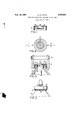
- FIG. 1 is a cross-sectional view of the cap taken on line II of FIG. 2,
- FIG. 2 is a view of the cap from underneath
- FIG. 3 is a cross-sectional view of the cap similar to FIG. 1, with the cap placed on the top of an aerosol bottle, the figure also illustrating a tool for crimping the cap over the top of the bottle, and
- FIG. 4 is a fragmental view showing the bottle in elevation with the cap crimped over the top.
- the cap 10 shown in FIGS. 1 and 2 includes a disc-like portion 11 which may be fiat as shown and is provided with a central aperture 12, and with two concentric flanges 13 and 14-.
- Flange 13 is an interior flange the inner diameter of which corresponds to the outer diameter of the shell of a valve mechanism for the aerosol bottle on which the cap 10 is to be used, whereas the flange 14 is an outer, flange for mounting the cap 10011 the top of said bottle.
- FIG. 3 illustrates the cap 10 in position on the top 7 portion of a bottle 16 with the shell 21 for the valve mechanism retained in position within the cap by. the interior flange l3, and with the conventional discharge tube 1 5 projecting upwardly from the shell 21 through the aperture 12 of the cap 10.
- the aerosol bottle is made of glass and the extreme end portion 22. of its top has a diameter of about 19 mm. and an interior diameter of about 12 mm, the top being provided with an annular recess or undercut 23a: a distance. belowthe extreme end portion 22 which is less than the height of the outer flange 14 of the cap 10. Therefore, when the cap 10 is placed in position on the bottle top, the free end portion or edge of the flange 14faces the annular recess 23.
- interior flange 13 of thecap may be a clearance fit wi h:
- mm; to about 3 mm. can easily and'eifectiv'ely be deformed by crimping or staking on to or over a flanged, collared or otherwise widened container aperture by a crimping pressure applied to said flanges atfriormal at- Caps for containers made of acet'a'l resin may be produced in various ,ways, for instance by injection moulding, by extrusion or by machining from rods or discs, de-
- the cap 10 is made of acetal resin and, preferably, of acetal resin made anddsold by E. I. do Pontde Nemours of U.S.A under the trade name Delrin.
- the outer diameter of the outer flange 14' of the cap is22.5 mm. andjits wall thickness 1.5 mm.
- the capli is secured to the extreme end portion22 of therbottle-top by a crimping operation, carried'out with a crimping collet including a plurality of tongues 17 which are arranged symmetrically about a. central ,iaxis andthe free ends of which tend to diverge from saidaXis, and an annular element 18 which surrounds the tongues and is so arranged relative thereto that its axial displacement towards the free ends of thetongues 17 forces these tree ends inwardly towards the central axis of the colle tr
- the crimping operation is-effectedias shown in FIG.
- the cap 10 is madezof Delrin or an equivalent! a'cetal resin,'as stated above, the crimping can be efiec'ted at normal atmospheric temperature. In this operation the outer flange'l of the cap is plastically deforincd without the occurrence of cracks or other irregularities in the flange 14 and/or any other part of the cap 10.
- the invention is applicable to all types of containers having an open neck with an annular end portion projecting over a recess, undercut or the like, and .is therefore not limited to the sealing of aerosol containers. Because of the metal-like mechanical proper- .ties of acetal resin it is possible to shape the cap as may be required, either as a plain cap or as a combined cap and valve housing, particularly when the cap is intended for use on aerosol containers.
- Caps made of acetal resin according to the present invention are entirely non-corrosive, and galvanic action between the cap and the container is entirely excluded due to the fact that acetal resin is essentially an electric insulator.
- Acetal resin can be made to various colours and, as
- caps or similar closures can be shaped variously as well, they can'be made to meet different requirements of appearance and sightliness as well.
- the present invention relates not only to a cap or like closure for use on a container, bottle or the like, but also has reference to a method of making a closed container, bottle or the like which method includes the steps of, first ly, selecting a'container or bottle having a neck portion with an aperture therein, a recess or undercut in the outer surface of said neck portion and an end of said neck portion which surrounds the said aperture and projects over the said recess or undercut, then, applying over said aperture a cap of acetal resin, said cap having a flange or skirt which when so applied surrounds and encloses said end portion and, finally, crimping or staking the free edge of the said fiange or skirt at normal atmospheric temperature around the said end and into the said recess or undercut for rigidly securing the cap to the said neck portion.
- the invention also encompasses the container, bottle or the like if closed with a cap of acetal resin by the said method, in the manner described above.
- a closure for a container having a neck portion forming a rim at its top with an opening defined within the rim and a recess defined in the outer surface of the neck portion below said rim comprising, a cap made of acetal resin having a flat portion adapted to close at least a portion of the opening of the container and including a skirt portion connected to the circumference of the flat portion and extending downwardly beyond the recess of the neck portion of the bottle, said cap having a wall thickness of from about between mm. to 3 mm.
- skirt portion permitting the skirt portion to be crimped to direct the acetal resin material into the recess of the container, said acetal resin material being capable of retaining its seat on the container with the crimped portion retained in the container recess when subjected to pressures of approximately 5 kilograms per square centimeter.
- a closure for a container particularly for an aerosol container adapted to be subjected to pressures of five kilograms per square centimeter, said container having a neck portion forming a rim at its top with an opening defined within the rim and a recess defined in .the outer surface ofthe neck portion below said rim, a cap made of acetal resin witha'top portion closing a portion of the opening of said container and having a central opening therein for receiving a projecting part of an aerosol element, a first flange portion extending from said flat top portion into the interior of said container and a second flange portion connected circumferentially tosaid flat top portion and fitted over the exterior surface of the rim of said container, said cap being of a thickness of from about A mm.
Landscapes
- Engineering & Computer Science (AREA)
- Mechanical Engineering (AREA)
- Chemical & Material Sciences (AREA)
- Dispersion Chemistry (AREA)
- Closures For Containers (AREA)
- Containers And Packaging Bodies Having A Special Means To Remove Contents (AREA)
- Nozzles (AREA)
Description
L. R. LITTLE Filed July 5, 1962 Feb. 16, 1965 CAPS FOR CONTAINERS, BOTTLES OR THE LIKE tive of the ambient temperature.
United States Patent 3,169,655 CAPS FOR CGNTAINERS, BOTTLES OR Tl m LHXE Lambert Ronald Little, Eastwood, New South Wales, Australia, assignor to Samuel Taylor Pty. Limited, Gore Hill, New South Wales, Australia, a corporation of Australia Filed July 5, 1962, Ser. No. 207,603 Claims priority, application Australia, July 5, 1961, 6,646/ 61 2 Claims. (Cl. 215-39) This invention has reference'to caps or the like adapted to permanently close an aperture for instance at the top of a container, bottle or the like.
It has for its object to provide a cap or similar closure which can easily be applied to such aperture and particularly to the neck portion of such a container or bottle by crimping or staking it over a widened collar, flange or like projection or projections therefrom, at normal atmospheric temperatures.
It is known that caps of aluminum, brass, bronze or other easily deformable metals having a wall thickness of the order of 1 mm. could be so applied at normal "temperature, but metal caps have the disadvantage that they are liable to be corroded or to be otherwise attacked by the liquid contents of such containers or bottles and,
besides this, galvanic action may occur if metal caps are.
otherwise producing rigid articles to effect the crimping or staking the flange of caps made of such a material havinging wall thicknesses of the order of 1 mm. at normal,
i.e. at atmospheric temperatures. All thermosetting or.
thermoahardening materials are obviously tin-suitable for this purpose as they lack'the required ductility irrespec- Ihermoplastic mate rials, on the other hand, require for crimping a considerably elevated temperature. The heating of the caps, however, prior to their application to container or bottle necks or tops would not only bea cumbersome procedure requiring special equipment, but it would also in most cases be mostinconvenientas the container or bottle would be heated at the same time at least locally. Many types of containers, particularly those which have been labelled or otherwise been finished, prior to being capped, cannot be subjected to heat. The same considerations would apply to containers filled with liquid or other substances, prior to capping, with a view to the etfect the heat may have on their contents.
Surprisingly it has hen found that the flanges of caps or similar closures made of acetal resin, which is a highly crystalline and stable form of polymerised formaldehyde, I and having a wall thickness within the range from about reference is made to the accompanying drawing. which, by way of example only, illustrates a specific embodiment of a cap for use on a conventional aerosol bottle. In said drawing FIG. 1 is a cross-sectional view of the cap taken on line II of FIG. 2,
FIG. 2 is a view of the cap from underneath,
FIG. 3 is a cross-sectional view of the cap similar to FIG. 1, with the cap placed on the top of an aerosol bottle, the figure also illustrating a tool for crimping the cap over the top of the bottle, and
FIG. 4 is a fragmental view showing the bottle in elevation with the cap crimped over the top.
The cap 10 shown in FIGS. 1 and 2 includes a disc-like portion 11 which may be fiat as shown and is provided with a central aperture 12, and with two concentric flanges 13 and 14-. Flange 13 is an interior flange the inner diameter of which corresponds to the outer diameter of the shell of a valve mechanism for the aerosol bottle on which the cap 10 is to be used, whereas the flange 14 is an outer, flange for mounting the cap 10011 the top of said bottle.
FIG. 3 illustrates the cap 10 in position on the top 7 portion of a bottle 16 with the shell 21 for the valve mechanism retained in position within the cap by. the interior flange l3, and with the conventional discharge tube 1 5 projecting upwardly from the shell 21 through the aperture 12 of the cap 10.
In the exampleillustrated the aerosol bottle is made of glass and the extreme end portion 22. of its top has a diameter of about 19 mm. and an interior diameter of about 12 mm, the top being provided with an annular recess or undercut 23a: a distance. belowthe extreme end portion 22 which is less than the height of the outer flange 14 of the cap 10. Therefore, when the cap 10 is placed in position on the bottle top, the free end portion or edge of the flange 14faces the annular recess 23. The
mm; to about 3 mm. can easily and'eifectiv'ely be deformed by crimping or staking on to or over a flanged, collared or otherwise widened container aperture by a crimping pressure applied to said flanges atfriormal at- Caps for containers made of acet'a'l resin may be produced in various ,ways, for instance by injection moulding, by extrusion or by machining from rods or discs, de-
pending on the required size'and/or-wallithickness.
- In order to more particularly describe the invention f f in the aperture of the bottle top 22, and the outer flange 14 is a'neat fit on the end portion 22 of the bottle top.
According to the invention the cap 10 is made of acetal resin and, preferably, of acetal resin made anddsold by E. I. do Pontde Nemours of U.S.A under the trade name Delrin. In the exampleshown the outer diameter of the outer flange 14' of the cap is22.5 mm. andjits wall thickness 1.5 mm.
The capli) is secured to the extreme end portion22 of therbottle-top by a crimping operation, carried'out with a crimping collet including a plurality of tongues 17 which are arranged symmetrically about a. central ,iaxis andthe free ends of which tend to diverge from saidaXis, and an annular element 18 which surrounds the tongues and is so arranged relative thereto that its axial displacement towards the free ends of thetongues 17 forces these tree ends inwardly towards the central axis of the colle tr The crimping operation is-effectedias shown in FIG. 3, by first placing the cap 10 on the'end portion 22of the bottle top as described above, then placing the collet over i the cap so that the tips-of the tongues 1'7 'face the free edge of ,the outer flange Mat locations opposite the recess 23 and,finally, by moving the annular element is towards the cap 18 whichcauses the tongues 17 to move radially inwardly and thereby to deform the free edge of the flange 14 in the manner illustrated in FIG. .4, the
tongues producing in said edge a series of indentations Since the cap 10 is madezof Delrin or an equivalent! a'cetal resin,'as stated above, the crimping can be efiec'ted at normal atmospheric temperature. In this operation the outer flange'l of the cap is plastically deforincd without the occurrence of cracks or other irregularities in the flange 14 and/or any other part of the cap 10.
Tests carried out with aerosol containers and caps of the dimensions stated above and made of acetal resin (Delrin) revealed that a tight seal was obtained by crimping the cap over the open top or neck of the containers in the manner described above. During these tests the filled bottles with the caps crimped on were immersed in water heated to a temperature of 70 C. and were retained in the warm water for periods of 9 minutes and over, so that interior pressures of up to 21 kg./cm. were produced inside the containers. Even at that pressure the seal remained perfect, no leakage of aerosol occurring.
These tests proved adequately that aerosol containers inwhich normally only pressures up to 5 kg./per cm. occur could safely be sealed with acetal caps crimped or staked on as described, by aprocess carried out at the ambient atmospheric temperature, i.e. by a cold process. In a further series of tests it was established that the cold crimping process can be used with equal advantage on acetal resin caps having flanges or skirts of wall thicknesses varying between about 4 mm. to about 3 mm.
When applying a cap made of acetal resin in accordance with the present invention to a bottle or container by crimping or staking, care must be taken to so adjust the crimping pressure-to the wall thickness of the cap flange or skirt, that the specific pressure within the material of the flange or skirt during the crimping or staking operation should be above the elastic limit of the cap material.
In the light of the foregoing description, it will be clear to the expert that the invention is applicable to all types of containers having an open neck with an annular end portion projecting over a recess, undercut or the like, and .is therefore not limited to the sealing of aerosol containers. Because of the metal-like mechanical proper- .ties of acetal resin it is possible to shape the cap as may be required, either as a plain cap or as a combined cap and valve housing, particularly when the cap is intended for use on aerosol containers.
, Caps made of acetal resin according to the present invention are entirely non-corrosive, and galvanic action between the cap and the container is entirely excluded due to the fact that acetal resin is essentially an electric insulator.
Acetal resin can be made to various colours and, as
caps or similar closures can be shaped variously as well, they can'be made to meet different requirements of appearance and sightliness as well. I
From the foregoing description 'it will be understood that the present invention relates not only to a cap or like closure for use on a container, bottle or the like, but also has reference to a method of making a closed container, bottle or the like which method includes the steps of, first ly, selecting a'container or bottle having a neck portion with an aperture therein, a recess or undercut in the outer surface of said neck portion and an end of said neck portion which surrounds the said aperture and projects over the said recess or undercut, then, applying over said aperture a cap of acetal resin, said cap having a flange or skirt which when so applied surrounds and encloses said end portion and, finally, crimping or staking the free edge of the said fiange or skirt at normal atmospheric temperature around the said end and into the said recess or undercut for rigidly securing the cap to the said neck portion.
It will further be appreciated that the invention also encompasses the container, bottle or the like if closed with a cap of acetal resin by the said method, in the manner described above.
What I claim is:
1. A closure for a container having a neck portion forming a rim at its top with an opening defined within the rim and a recess defined in the outer surface of the neck portion below said rim, comprising, a cap made of acetal resin having a flat portion adapted to close at least a portion of the opening of the container and including a skirt portion connected to the circumference of the flat portion and extending downwardly beyond the recess of the neck portion of the bottle, said cap having a wall thickness of from about between mm. to 3 mm. and permitting the skirt portion to be crimped to direct the acetal resin material into the recess of the container, said acetal resin material being capable of retaining its seat on the container with the crimped portion retained in the container recess when subjected to pressures of approximately 5 kilograms per square centimeter.
2. A closure for a container, particularly for an aerosol container adapted to be subjected to pressures of five kilograms per square centimeter, said container having a neck portion forming a rim at its top with an opening defined within the rim and a recess defined in .the outer surface ofthe neck portion below said rim, a cap made of acetal resin witha'top portion closing a portion of the opening of said container and having a central opening therein for receiving a projecting part of an aerosol element, a first flange portion extending from said flat top portion into the interior of said container and a second flange portion connected circumferentially tosaid flat top portion and fitted over the exterior surface of the rim of said container, said cap being of a thickness of from about A mm. to 3 mm. and being capable of being crimped with portions thereof and being capable of being forced into the recess of said container, said acetal resin being capable of withstanding the pressures within said container without causing the crimped portion to become loosened from the recess of the container.
References Cited by the Examiner UNITED STATES PATENTS 1,002,815 9/11 Bond ;5342 2,139,572 12/38 Booth 5342 2,200,600 5/40 Grapp 2l539 2,327,454 8/43 Punte Q 21539 2,543,774 3/51 Gora 21539 -2,741,388 4/56 Rubin 2l539 THERON E. CONDON, Primary Examiner.
EARLE J DRUMMOND, GEORGE O. RALSTON, I
. y Examiners.
Claims (1)
1. A CLOSURE FOR A CONTAINER HAVING A NECK PORTION FORMING A RIM AT ITS TOP WITH AN OPENING DEFINED WITHIN THE RIM AND A RECESS DEFINED IN THE OUTER SURFACE OF THE NECK PORTION BELOW SAID RIM, COMPRISING, A CAP MADE OF ACETAL RESIN HAVING A FLAT PORTION ADAPTED TO CLOSE AT LEAST A PORTION OF THE OPENING OF THE CONTAINER AND INCLUDING A SKIRT PORTION CONNECTED TO THE CIRCUMFERNCE OF THE FLAT PORTION AND EXTENDING DOWNWARDLY BEYOND THE RECESS OF THE NECK PORTION OF THE BOTTLE, SAID CAP HAVING A WALL THICKNESS OF FROM ABOUT BETWEEN 1/4 MM. TO 3 MM. AND PERMIT-
Applications Claiming Priority (1)
| Application Number | Priority Date | Filing Date | Title |
|---|---|---|---|
| AU6646/61A AU258985B2 (en) | 1961-07-05 | Improvements in or relating to caps for containers, bottles orthe like |
Publications (1)
| Publication Number | Publication Date |
|---|---|
| US3169655A true US3169655A (en) | 1965-02-16 |
Family
ID=3697209
Family Applications (1)
| Application Number | Title | Priority Date | Filing Date |
|---|---|---|---|
| US207603A Expired - Lifetime US3169655A (en) | 1961-07-05 | 1962-07-05 | Caps for containers, bottles or the like |
Country Status (3)
| Country | Link |
|---|---|
| US (1) | US3169655A (en) |
| FR (1) | FR1328635A (en) |
| GB (1) | GB999159A (en) |
Cited By (2)
| Publication number | Priority date | Publication date | Assignee | Title |
|---|---|---|---|---|
| US3910445A (en) * | 1974-05-31 | 1975-10-07 | Vidriera Monterrey S A | Container closure |
| US3964627A (en) * | 1972-12-15 | 1976-06-22 | Bunde Glass Gmbh | Container for an injection liquid, in the form of a flask closed by a curl-on cap |
Families Citing this family (7)
| Publication number | Priority date | Publication date | Assignee | Title |
|---|---|---|---|---|
| US6681946B1 (en) | 1998-02-26 | 2004-01-27 | Becton, Dickinson And Company | Resealable medical transfer set |
| US6382442B1 (en) * | 1998-04-20 | 2002-05-07 | Becton Dickinson And Company | Plastic closure for vials and other medical containers |
| US6003566A (en) * | 1998-02-26 | 1999-12-21 | Becton Dickinson And Company | Vial transferset and method |
| US6378714B1 (en) | 1998-04-20 | 2002-04-30 | Becton Dickinson And Company | Transferset for vials and other medical containers |
| US6957745B2 (en) | 1998-04-20 | 2005-10-25 | Becton, Dickinson And Company | Transfer set |
| US6681475B2 (en) | 1998-04-20 | 2004-01-27 | Becton Dickinson And Company | Method of sealing a medical container with a plastic closure |
| ATE348052T1 (en) * | 1999-10-20 | 2007-01-15 | Becton Dickinson Co | PLASTIC CLOSURE FOR VIALS OR OTHER MEDICAL CONTAINERS |
Citations (6)
| Publication number | Priority date | Publication date | Assignee | Title |
|---|---|---|---|---|
| US1002815A (en) * | 1908-12-07 | 1911-09-05 | Bond Bottle Sealing Company | Sealing and capping bottles. |
| US2139572A (en) * | 1934-04-16 | 1938-12-06 | Crown Cork & Seal Co | Method and apparatus for applying closures |
| US2200600A (en) * | 1938-02-02 | 1940-05-14 | George L Grapp | Closure for bottles |
| US2327454A (en) * | 1939-11-02 | 1943-08-24 | Continental Can Co | Padless crown cap |
| US2543774A (en) * | 1949-03-08 | 1951-03-06 | Gora Lee Corp | Container closure |
| US2741388A (en) * | 1953-09-03 | 1956-04-10 | Rubin Oscar | Closures |
-
1962
- 1962-07-03 GB GB25426/62A patent/GB999159A/en not_active Expired
- 1962-07-04 FR FR902952A patent/FR1328635A/en not_active Expired
- 1962-07-05 US US207603A patent/US3169655A/en not_active Expired - Lifetime
Patent Citations (6)
| Publication number | Priority date | Publication date | Assignee | Title |
|---|---|---|---|---|
| US1002815A (en) * | 1908-12-07 | 1911-09-05 | Bond Bottle Sealing Company | Sealing and capping bottles. |
| US2139572A (en) * | 1934-04-16 | 1938-12-06 | Crown Cork & Seal Co | Method and apparatus for applying closures |
| US2200600A (en) * | 1938-02-02 | 1940-05-14 | George L Grapp | Closure for bottles |
| US2327454A (en) * | 1939-11-02 | 1943-08-24 | Continental Can Co | Padless crown cap |
| US2543774A (en) * | 1949-03-08 | 1951-03-06 | Gora Lee Corp | Container closure |
| US2741388A (en) * | 1953-09-03 | 1956-04-10 | Rubin Oscar | Closures |
Cited By (2)
| Publication number | Priority date | Publication date | Assignee | Title |
|---|---|---|---|---|
| US3964627A (en) * | 1972-12-15 | 1976-06-22 | Bunde Glass Gmbh | Container for an injection liquid, in the form of a flask closed by a curl-on cap |
| US3910445A (en) * | 1974-05-31 | 1975-10-07 | Vidriera Monterrey S A | Container closure |
Also Published As
| Publication number | Publication date |
|---|---|
| GB999159A (en) | 1965-07-21 |
| FR1328635A (en) | 1963-05-31 |
Similar Documents
| Publication | Publication Date | Title |
|---|---|---|
| US3270904A (en) | Press-on turn-off cap | |
| US4546892A (en) | Plastic sealing screw cap with improved tamper-proof strip | |
| US4093094A (en) | Home canning system | |
| US4153172A (en) | Container safety closure | |
| US3145872A (en) | Captive cap for container | |
| US3163318A (en) | Flared container cap | |
| US3169655A (en) | Caps for containers, bottles or the like | |
| US3443006A (en) | Method of making gasketed mounting cups for pressurized aerosol containers | |
| US3352448A (en) | Resilient closure | |
| US4487325A (en) | Crown closures and containers | |
| JPS59124270A (en) | Screw type cap for vessel | |
| CA2286584A1 (en) | Plastic closure cap comprising a detachable annular guarantee band and an inner sealing | |
| KR940014093A (en) | Plastic recycling bins and methods for manufacturing and recycling them | |
| US3372833A (en) | Stoppers for receptacles having screw-threaded necks | |
| EP0497969A1 (en) | Composite closure with seal proportioning lip | |
| EP0504650A1 (en) | Method of and sealing material for manufacturing a lid seal for plastic lids of blow-moulded plastic drums | |
| US3247994A (en) | Plastic caps for use as closure for containers | |
| US3417177A (en) | Method of making gasketed closures | |
| US4429802A (en) | Linerless closure cap | |
| US3004297A (en) | Method for forming a gasket | |
| US4821911A (en) | Closing cover for a metal container | |
| US3994410A (en) | Plastic bottle cap | |
| US4290535A (en) | Sealing bung for bottle closures | |
| US3780897A (en) | Stoppers | |
| US3191815A (en) | Tops for aerosol containers |